Digital Security Controls SKYROUTE SKYROUTE, SKYROUTE MAX or SKYROUTE UT User Manual LINKS2150 v1 4W im na 29004010 r1
Digital Security Controls Ltd. SKYROUTE, SKYROUTE MAX or SKYROUTE UT LINKS2150 v1 4W im na 29004010 r1
Contents
- 1. Users Manual
- 2. revised manual wrt FCC correspondence 18131
Users Manual
Installation
Manual
Version 1.0
WARNING:WARNING:
WARNING:WARNING:
WARNING: You must be enrolled with Connect 24 You must be enrolled with Connect 24
You must be enrolled with Connect 24 You must be enrolled with Connect 24
You must be enrolled with Connect 24
before activating this unit. Call 1-888-251-7458 inbefore activating this unit. Call 1-888-251-7458 in
before activating this unit. Call 1-888-251-7458 inbefore activating this unit. Call 1-888-251-7458 in
before activating this unit. Call 1-888-251-7458 in
the U.S. or 1-888-955-5583 in Canadathe U.S. or 1-888-955-5583 in Canada
the U.S. or 1-888-955-5583 in Canadathe U.S. or 1-888-955-5583 in Canada
the U.S. or 1-888-955-5583 in Canada
Skyroute
Skyroute UT
Skyroute max

FCC COMPLIANCE STATEMENT
CAUTION
: Changes or modifications not expressly approved by SG Wireless Communications could void your authority to
use this equipment.
This equipment has been tested and found to comply with the limits for a Class B digital device, pursuant to Part 15 and Part 22 of the
FCC Rules. These limits are designed to provide reasonable protection against harmful interference in a residential installation. This
equipment generates, uses and can radiate radio frequency energy and, if not installed and used in accordance with the instructions, may
cause harmful interference to radio communications. However, there is no guarantee that interference will not occur in a particular
installation. If this equipment does cause harmful interference to radio or television reception, which can be determined by turning the
equipment off and on, the user is encouraged to try to correct the interference by one or more of the following measures:
• Re-orient the receiving antenna.
• Increase the separation between the equipment and receiver.
• Connect the equipment into an outlet on a circuit different from that to which the receiver is connected.
• Consult the dealer or an experienced radio/television technician for help.
The user may find the following booklet prepared by the FCC useful: “How to Identify and Resolve Radio/Television Interference Prob-
lems”. This booklet is available from the U.S. Government Printing Office, Washington D.C. 20402, Stock # 004-000-00345-4.
INDUSTRY CANADA COMPLIANCE STATEMENT
This Class B digital apparatus meets all requirements of the Canadian interference-causing equipment regulations.
Cet appareil numérique de la Classe B respecte toutes les exigences de règlement sur le matériel brouilleur du Canada.
WARNING:To satisfy FCC RF exposure requirements for mobile transmitting
devices, a separation distance of 30 cm or more should be maintained
between the antenna of this device and persons during device operation. To
ensure compliance, operations at closer than this distance is not
recommended.

Table of Contents
Generic Reporting 5
Description ................................................................... 5
Normal Alarm Condition ................................................ 5
Notice .......................................................................... 5
STEP 4 - Programming Sections 6
Configuration Options - Section [006] ............................. 6
Skyroute
max
Transceiver SID (System ID) - Section [007] . 6
Skyroute
max
Test Time - Section [010] ........................... 6
Test Transmission Day Mask - Section [011] .................... 6
STEP 5 - Activating the Skyroute
max
Transceiver 6
Calling Connect24 ......................................................... 6
Transmitting and Receiving ............................................. 6
Testing Your Control to the Central Station 6
Skyroute
max
Programming with PC4020
[00][18]Skyroute
max
Programming 7
[00][18] Skyroute
max
Programming .............................. 7
[006]Skyroute max Configuration Options ....................... 7
[007Home SID Number .................................................. 7
[010]Skyroute max Test Time ......................................... 7
[011]Test Transmission Day Mask ................................... 7
[013]Skyroute max Test Rates ........................................ 7
Sections [030]-[047] ..................................................... 8
Skyroute max Transceiver Trouble Shooting 12
Antenna Relocation Diagram 13
Supervised Power Supply Connection Diagram 14
Standard Connection with PC4020 15
For Your Records 16
Appendix A – Reporting Codes for SIA and Contact ID 17
Appendix B - Zone Reporting codes 18
Limited Warranty BACK
Contents ii
Important Information ................................................. ii
Skyroute
max
Glossary of Terms ii
Introducing the Skyroute
max
Transceiver 1
Specifications .............................................................. 1
Communications Method ............................................ 1
Dual Path Communications ......................................... 1
Antenna ....................................................................... 1
RF Power Output ......................................................... 1
Power Supply Ratings .................................................. 1
Dimension ................................................................... 1
Weight ......................................................................... 1
Operating Temperature .................................................. 1
How the Skyroute
max
Transceiver Works 1
Cellemetry Communication ............................................ 1
Installation 2
Mounting the Skyroute
max
Transceiver .......................... 2
Combus Connection ....................................................... 2
Bell IN Terminal ............................................................. 2
Bell OUT Terminal .......................................................... 2
Tamper Terminal ........................................................... 2
Secure Installation ......................................................... 2
Connection Diagram ...................................................... 2
STEP 1 - Location of the Skyroute
max
Unit 3
Relocating the Antenna 3
Mounting the Antenna ................................................... 3
Relocating the Skyroute
max
Transceiver 4
Skyroute
max
Transceiver Trouble Supervision 4
STEP 2 - Enrolling Skyroute
max
with 4020 4
STEP 3 - Defaulting the Skyroute
max
5
i

Contents
Important Information
This manual is based on the production version of the included
wireless device. Software changes may have occurred after the
revision of this manual.
Caution
Any changes or modifications not expressly approved in this
document could void your warranty for this equipment and void
your authority to use this equipment.
ii
Warning
Only use the antenna provided by DSC / Sur-Gard. The use of any
other type will invalidate the warranty and may be dangerous.
Customer Service
For customer support please call Sur-Gard technical information
at 1-800-503-5869 or e-mail us at support@sur-gard.com.
The following is a description of various terms used with
regards to cellemetry technology.
Electronic Serial Number (ESN)
The ESN is used to carry data information in a Cellemetry
Network
Mobile Identification Number (MIN)
A 10 digit decimal number used for registrations and pages.
Page
A transmission that is sent from the Cellemetry Gateway to the
Cellemetry radio.
Registration
A transmission that is sent from the Cellemetry radio to the
Cellemetry Gateway.
System Identification Number (SID)
Identification of the Cellemetry Provider.
Switch Number (SNO)
Switch number the Cellemetry radio uses to transmit pages to
the Cellemetry gateway.
Clearing House
The clearing house is a routing center that automatically forwards
data between Skyroute
max
transmitters and central stations.
Skyroute
max
Tranceiver Glossary of Terms
Introducing the Skyroute
max
Transceiver
The Skyroute
max
transceiver offers a new wireless communica-
tion method for the transmission of event information using the
Cellemetry service. Events are transmitted from the Skyroute
max
transceiver via the Cellemetry network to the clearing house and
then to the Central Station in a fast, reliable manner. Skyroute
max
has been designed for simple and straightforward installation.
Using the Combus technology, wiring connections are made
directly between Skyroute
max
and the security control panel.
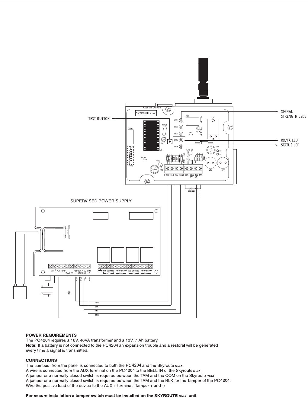
Specifications
Compatible Control Panels
• DSC PC4020 software version v3.2 or higher
Communication Method
• AMPS Control Channel
Dual Path Communications
• The system can be used as the sole method of
communication to the monitoring station or as a dual
transmission path with the standard land line.
Please contact your monitoring station on
dual signal communication.
Antenna
• 3 dB gain, TNC connector
• Extension Kits available:
LAE – 3 The 3 Foot Antenna Kit for Skyroute
max
Transceiver
LAE – 15 The 15 Foot Antenna Kit for Skyroute
max
Transceiver
LAE – 25 The 25 Foot Antenna Kit for Skyroute
max
Transceiver
RF Power Output
• 3.0 Watts maximum
Power Supply Ratings
• 12 VDC @30mA, from Panel Combus
• 12 VDC, from Bell Circuit
Current in Standby 90mA
Current when Receiving 135mA
Current when Transmitting 1.3A
•
For DSC PC4020 the required minimum transformer is a
16VAC 40 VA. The minimum Battery requirement is 12Vdc
7 Ah.
Dimension
• 3.5” x 4.6” x 1.8” (85 mm x 115 mm x 45 mm)
Weight
• 0.5 lbs. (0.2 kg)
Operating Temperature
•0
oC - 49oC (32oF - 120oF)
• 90% humidity, non condensating
Cellemetry Communication
The Skyroute
max
transceiver communicates using the control
channel of the existing cellular network. Signals are routed to the
Cellemetry gateway via the SS7 cellular network. A clearing house
then receives the signals and forwards the events to the central station.
Upon receiving an acknowledgement signal from the central station,
the clearing house then returns a confirmation of delivery signal to the
Skyroute
max
transceiver over the network. For transmission sequence
see drawing below:
1
How the Skyroute
max
Transceiver Works
that would usually connect to the control panel BELL+
terminal. This output is powered through the 5A fuse for
protection of the radio transmitting power.
Tamper Terminal
Connect TAM and COM to a normally closed switch that will
be used to monitor tamper. If no tamper switch is desired, place
a wire between TAM and COM.
Secure Installation
For a secure installation, the Skyroute
max
transceiver module and
its host panel must be locked and protected. An instant trip IR sensor
would be the most appropriate for supervision of the panel. A
cabinet tamper switch connected to the TAM terminal of the
Skyroute
max
transceiver is also suggested.
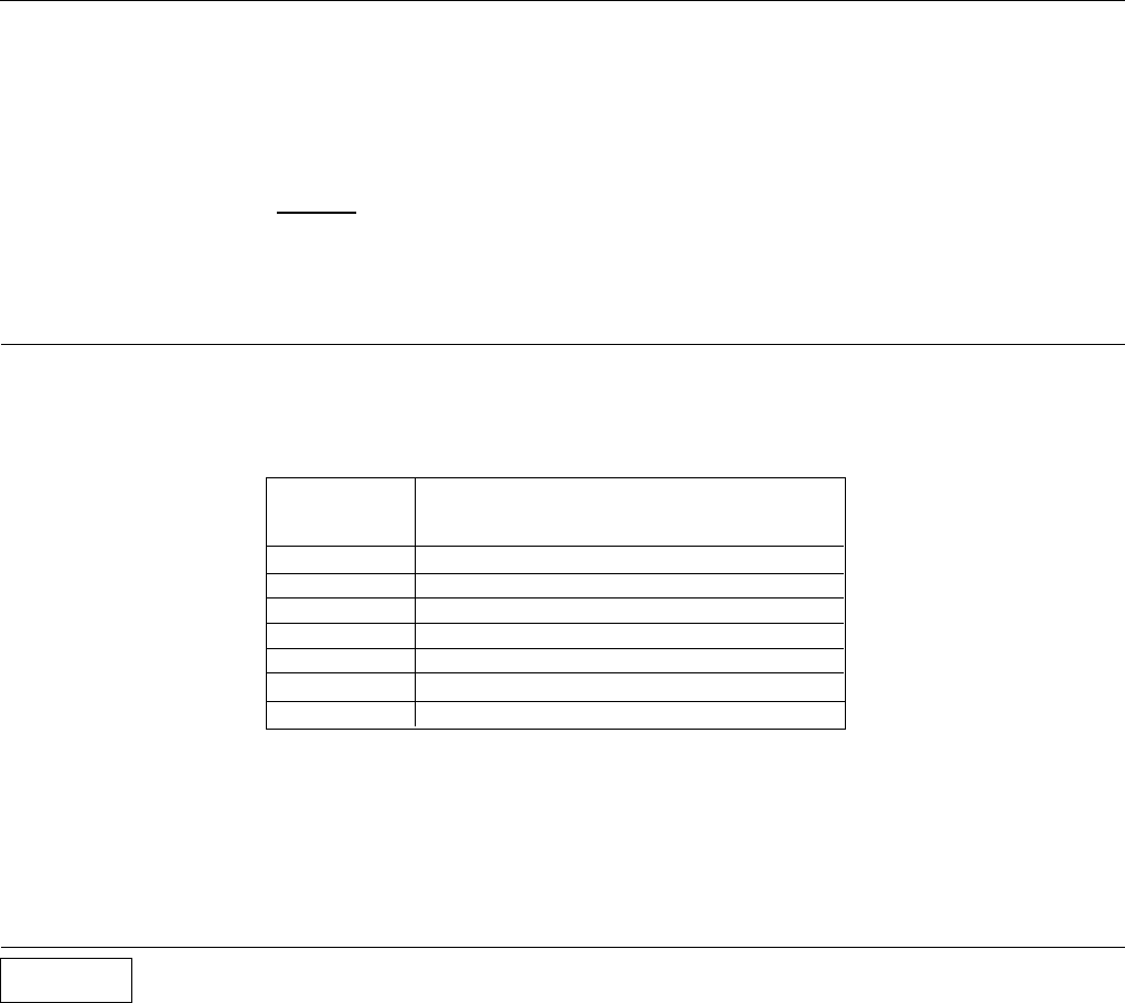
Relocating the Antenna
If a suitable location is not available for proper Cellemetry
coverage, obtain an Antenna Extension Bracket kit from your
DSC/Sur-gard supplier. Each kit contains an extension
Connection Diagram
Installation
It is mandatory that the power be removed from the
system before any wiring changes are performed on the
Skyroute
max
module. Neglecting to do so will result in
damage to the Cellemetry modem.
Mounting the Skyroute
max
Transceiver
The Skyroute
max
transceiver can be mounted in the upper right
hand corner of the panel’s cabinet through the knock out. The
Skyroute
max
transceiver case attaches to the panel’s cabinet
through the use of clips and two screws.
Combus Connection
The Skyroute
max
transmitter has 4 terminals marked red, black,
yellow and green. Connect these four terminals to the 4 terminals
on the main control panel marked COMBUS (red, blk, yel and grn).
Bell IN Terminal
This terminal is used to power the cellemetry modem. This
connects to the BELL + on the control panel. No other wire should
be connected to the Bell+ of the control panel.
An extra power supply can be used to power the modem if it is
not located near the main control panel or where the
system cannot provide enough power for the transmis-
sions. Connect the positive of the power supply to the BELL
IN and the negative to the COM to ensure proper ground-
ing.
Bell OUT Terminal
This terminal is used to power the siren or any other devices
2
As indicated, the Skyroute
max
unit is a combus unit,
which can be located away
from the control when
required to provide
maximum signal strength.
cable, a mounting bracket, instructions, and all required
hardware. Three lengths of extension cable are available:
Extension Kit Length of cable
LAE-3 3 feet (0.91 m)
LAE-15 15 feet (4.57 m)
LAE-25 25 feet (7.62 m)
Only use the Extension Kits to extend the mounting range
of the antenna. Do not cut or splice the extension cable.
The maximum distance between the Skyroute
max
trans-
ceiver and the antenna is 25 feet (7.62 m) as obtained by
using the LAE-25 Extension Kit. Make sure the antenna is in
a physically secured location to avoid tampering.
Secure the TNC connector from the Extension Kit to the
mounting bracket, ensuring that the star washers make
solid electrical contact with the mounting bracket.
Remove the antenna from the Skyroute
max
module and
connect the extension cable to the TNC connector on the
module. Secure the antenna to the TNC connector mounted
on the Extension Kit Mounting Bracket. Locate the mount-
ing bracket and antenna away from possible sources of
electrical interference. Moving the antenna just a short
distance will likely be adequate. Temporarily secure the
mounting bracket in the new location and proceed with
3
Location of the Skyroute
max
Unit
It is very important to determine the best location for maximum signal strength.
Verify signal strength prior to installation!
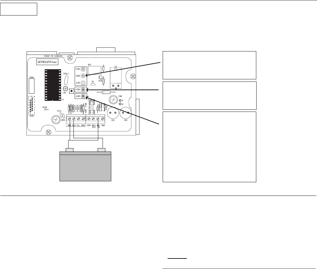
12V 7Ah Battery12V 7Ah Battery
12V 7Ah Battery12V 7Ah Battery
12V 7Ah Battery
+-
LED 1: Good signal strength
LED 2: Acceptable signal strength
LED 3: Poor signal strength
LED 4: One blink = Transmit TX
Two blinks = Receive RX
LED 5: Status (number of blinks)
1: Normal (activated)
2: Radio not power-up
3: Failed self-test
4: No cell network
5: Fail to communicate
6: Ready to activate
8: Unit not enrolled with 4020
STEP 1
testing. If the test is successful, permanently secure the
mounting bracket and antenna at the new location.
Mounting the Antenna
NOTE: The antenna should always be attached to the
Skyroute max Transceiver for proper operation. The unit
will not function properly if the antenna is not installed.
4
Relocating the Skyroute
max
Transceiver
Since the Skyroute
max
transceiver is a Combus accessory, it is possible to relocate the module up to 1000 feet from the main control
panel when the panel is not located in a good cellemetry coverage area (a control panel installed in a vault for example). When relocating
the module, follow theses rules:
• Maximum of 1000 feet from the main control. Combus (Red, Black, Yellow, Green) from the panel to the Skyroute
max
transceiver.
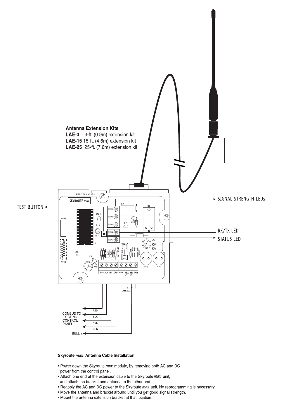
• A supervised power supply 12V@1A (like the PC4204) must be used (see diagram on page 14).
• The power supply (+ positive) is connected to the Skyroute
max
transceiver (BELL IN) terminal and the power supply
(–negative) to the Skyroute
max
transceiver (COM) terminal.
• The cabinet must be installed in a secure location and should have a tamper circuit connected to the Skyroute
max
(TAM and
COM) terminals.
Skyroute
max
Transceiver Trouble Supervision
The Skyroute
max
transceiver automatically monitors its operation and indicates trouble conditions by flashing LED5 on the circuit
board. LED5 normally flashes once every 2 seconds when the Skyroute
max
transceiver is on stand-by (ready to transmit) mode. Troubles
are indicated when LED5 flashes more than once every 2 seconds. Shown below is the number of flashes used to indicate each trouble
condition.
(1) Radio is operating normally: Skyroute
max
transceiver is ready to transmit.
(2) Radio not powered or not responding: Skyroute
max
transceiver initialization of Cellemetry modem has failed.
(3) Failed self-test: A self-test of the Cellemetry module has failed.
(4) Service not available: The Cellemetry modem has failed to register with the cellular network.
(5) Failure to communicate: A signal has not been successfully communicated to the central station.
(6) Not connected to clearing house: The Skyroute
max
transceiver has not been activated.
(8) Module not enrolled with panel: The Skyroute
max
transceiver is not addressed by the control panel.
Enrolling Skyroute
max
with PC4020
Once all the wiring is complete, you must enroll the module:
1. Enter installer’s programming by pressing [*][8][Installer’s Code]
2. Scroll to “Module Hardware” and press the [*] key.
3. Scroll to “Enroll Module” and press the [*] key.
4. Scroll through the different modules until “Alternate Comms” is displayed. Press the [*] key.
5. The message “Create Tamper on Desired Unit” will be displayed. To create the required tamper, secure the tamper zone on
the module and then open it. The transition from secure to violated enrolls the module. After this is done, the keypad will
display the module number and confirm enrollment “Alternate Comms Mod 01 Enrolled”.
For more information regarding module enrollment, see the control panel Installation Manual.
Number Function of Flashes
of Flashes
1 Radio is operating normally
2 Radio is not powered, or not responding
3 Failed selftest
4 Service is not available
5 Failure to communicate
6 Ready to activate
8 Module not enrolled with panel
STEP 2

STEP 3
Defaulting the Skyroute
max
A default is performed by entering installers programming, [*][8][Installers Code]. Entering section [00][18] will enter the Skyroute
max
programming, by entering [00] or [22] in subsection [099] the Skyroute
max
will be defaulted.
[00] defaults the unit into full reporting.
[22] defaults the unit into generic reporting.
Generic Reporting
Description
The unit can be set to Full Reporting, or Generic Only. This is to be used on systems that have a telephone line as the primary means of communication
and Skyroute
max
as a redundant. This option is not meant to make the Skyroute
max
a back-up unit, but to avoid duplicate signals and large delays
between signals at the central station. The only zone signals affected are Burglary. The system has one timer for each partition, the time is 5 minutes.
Normal Alarm condition
General reporting will send a generic alarm signal to the central station via the Cellemetry network when a burglary signal is generated. If
multiple burglaries are activated, the first will trigger the unit to transmit the associated generic signal. Once the Skyroute
max
has transmitted
the generic signal it ignores all other burglary alarms on the system for a period of 5 minutes. The Skyroute
max
unit will ignore any other burglary
alarms that trigger the general transmission during the period the timer is active. If a new alarm of another type (trouble) is triggered then the signal
is sent immediately with the corresponding zone number. After the timer has elapsed the unit will then resume standard operation. If a new burglary
alarm occurs after the timer has expired, the sequence restarts. All other events will be transmitted via the unit if the appropriate toggle options are
enabled. This is accomplished by defaulting the Skyroute
max
with a [22] at subsection [099]
Notice
A system default must be performed before activation. This is necessary to configure the communication format.
NOTE-When the system is defaulted for Generic Reporting the transmission options are as follows. If a signal group
is required, activate the corresponding option.
[030] SYSTEM EVENTS (PARTITION 0) TRANSMISSION OPTIONS SECTION A
Default Option ON Option OFF
ON I_____I Option 1 Alarms Disabled
OFF I_____I Option 2 Alarm Restorals Disabled
OFF I_____I Option 3 Tampers Disabled
OFF I_____I Option 4 Tamper Restorals Disabled
OFF I_____I Option 5 Closings Disabled
OFF I_____I Option 6 Openings Disabled
OFF I_____I Option 7 Maintenance Alarms Disabled
OFF I_____I Option 8 Maintenance Alarm Restorals Disabled
[031] SYSTEM EVENTS (PARTITION 0) TRANSMISSION OPTIONS SECTION B
Default Option ON Option OFF
ON I_____I Option 1 Trouble Disabled
OFF I_____I Option 2 Trouble Restorals Disabled
OFF I_____I Option 3 Bypass Disabled
OFF I_____I Option 4 Unbypass Disabled
OFF I_____I Option 5 Supervisory Alarm Disabled
OFF I_____I Option 6 Supervisory Restoral Disabled
OFF I_____I Option 7 Access Control Disabled
OFF I_____I Option 8 Miscellaneous Disabled
5

6
Programming Sections
All programming on the Skyroute
max
transceiver is done in the installer’s programming mode. Refer to the control panel’s Installation Manual
for instructions on how to enter installer’s programming. From installer’s programming, enter section [00][18] to go to the Skyroute
max
programming sections.
Configuration Options……………………………………Section [006]
Channel A enable/disable…………..option [1]
This option must be selected when the Cellemetry provider is an “A” side carrier.
Channel B enable/disable…………..option[2]
This option must be selected when the Cellemetry provider is a “B” side carrier.
Home System only enable/disable…option[3]
This option must be programmed to ensure that the Skyroute
max
transceiver is communicating using the proper carrier. When
selected, the transceiver will only use towers with the same SID (as programmed in section [007]).
To Activate the Skyroute
max
Module in Home Mode
1. Select a channel, A or B, in address [006] (Option 1 or 2)
2. Program FF into section[099] to restart the unit
3. Wait for signal strength.
4. Enter in address [007] the Home SID number in hexadecimal format.
5. Select Home Mode (Option 3) and deactivate A or B channel in address [006].
Note: A restart of the unit is required when changes are made in section [006] . To perform the restart programm FF into
section [099]
Skyroute
max
Transceiver SID (System ID)…………………..Section [007]
Please refer to the SID table included with the Skyroute
max
Module to find out the SID number for your area.
Skyroute
max
Test Time………………………………...………Section [010]
Enter in this section the time of the day (24 hour format) that you want the test transmission to be sent.
NOTE: Keypad will display ENT HEX. Simply enter value from 0000 to 2359.
Test Transmission Day Mask…………………….……….Section [011]
Select in this section the day of the week you want the test transmission to be sent.
STEP 4
Activating the Skyroute
max
Transceiver
Before activating the Skyroute
max
transceiver, ensure that the control panel is wired, programmed and operating properly.
Make sure that the Skyroute
max
transmitter is properly connected to the Combus and to the bell positive circuit. When power
is applied to the system, the Skyroute
max
will perform self-diagnostics for a few seconds, before giving visual feedback
by indicating signal strength on LED1, LED2 or LED3. A complete default of the Skyroute
max
module should always be
performed before any other programming is done. See Default section for details.
Calling Connect 24
Once the Skyroute
max
transceiver is indicating the signal strength of the network, and the status indicator (LED5) is
blinking 6 times (not connected to the clearing house), you are ready to call Connect 24’s Voice Response Unit. Follow
the voice prompt and when asked to perform a test, press on SW1 on the Skyroute
max
transceiver to transmit a test
signal. When transmitting, LED4 blinks once. If the test is successful, the VRU will give you a confirmation and LED5 will
then blink steady every second. Refer to the Connect24 information package for more information on the activation
process.
Phone number for VRU: CANADA: 1-877-759-7688 U.S.: 1-888-251-7554
NOTE: The confirmation of a successful test from Connect 24 does not guarantee proper transmission of event to your
central station. You must perform normal tests with your monitoring station after activation with Connect 24.
Transmitting and Receiving
LED4 on the Skyroute
max
module will blink once (1) to indicate the Cellular Tower has received the signal. It will blink twice (2)
to indicate the Alarm Central Station has received and acknowledged the signal.
STEP 5
Testing Your Control to the Central Station
Test all zones to your Central Station on the telephone line only. After all zone testing, connect Skyroute
max
and verify communica-
tion to Central Station.

Skyroute
max
Programming with PC4020
[00][18] Skyroute
max
Programming
[006] Skyroute
max
Configuration Options
Default Option ON Option OFF
OFF I_____I Option 1 A Channel Selected A Channel Not Selected
ON I_____I Option 2 B Channel Selected B Channel Not Selected
OFF I_____I Option 3 Home System Only Not in Home System Operation
OFF I_____I Options 4 to 8 For system use do not modify.
[007] Home SID Number
Default
0000 I_____I_____I_____I_____I This is the SID (in Hex) of the cellular service that is available
on the current channel.
[010] Skyroute
max
Test Time
Default
9999 I_____I_____I_____I_____I 0000-2359 (in 24 hour time)
NOTE: Keypad will display ENT HEX. Simply enter value
from 0000 to 2359.
[011] Test Transmission Day Mask
Default Option ON Option OFF
OFF I_____I Option 1 Test on Sunday Disabled
OFF I_____I Option 2 Test on Monday Disabled
OFF I_____I Option 3 Test on Tuesday Disabled
OFF I_____I Option 4 Test on Wednesday Disabled
OFF I_____I Option 5 Test on Thursday Disabled
OFF I_____I Option 6 Test on Friday Disabled
OFF I_____I Option 7 Test on Saturday Disabled
OFF I_____I Option 8 For Future Use
[013] Skyroute
max
Test Rates
Default
OFF I_____I Option 1 For Future Use
OFF I_____I Option 2 Daily Test Disabled
ON I_____I Option 3 Weekly Test Disabled
OFF I_____I Options 4 to 8 For Future Use
7

Sections [030] to [047] will disable groups of reporting codes.
[030] System Event (Partition 0) Transmission Options Section A
Default Option ON Option OFF
ON I_____I Option 1 Alarms Disabled
OFF I_____I Option 2 Alarm Restorals Disabled
OFF I_____I Option 3 Tampers Disabled
OFF I_____I Option 4 Tamper Restorals Disabled
OFF I_____I Option 5 Closings Disabled
ON I_____I Option 6 Openings Disabled
ON I_____I Option 7 Maintenance Alarms Disabled
ON I_____I Option 8 Maintenance Alarm Restorals Disabled
[031] System Events (Partition 0) Transmission Options Section B
Default Option ON Option OFF
ON I_____I Option 1 Trouble Disabled
ON I_____I Option 2 Trouble Restorals Disabled
OFF I_____I Option 3 Bypass Disabled
OFF I_____I Option 4 Unbypass Disabled
OFF I_____I Option 5 Supervisory Alarm Disabled
OFF I_____I Option 6 Supervisory Restoral Disabled
OFF I_____I Option 7 Access Control Disabled
OFF I_____I Option 8 Miscellaneous Disabled
[032] Partition 1 Transmission Options Section A
Default Option ON Option OFF
ON I_____I Option 1 Alarms Disabled
OFF I_____I Option 2 Alarm Restorals Disabled
OFF I_____I Option 3 Tampers Disabled
OFF I_____I Option 4 Tamper Restorals Disabled
OFF I_____I Option 5 Closings Disabled
ON I_____I Option 6 Openings Disabled
ON I_____I Option 7 Maintenance Alarms Disabled
ON I_____I Option 8 Maintenance Alarm Restorals Disabled
[033] Partition 1 Transmission Options Section B
Default Option ON Option OFF
ON I_____I Option 1 Trouble Disabled
ON I_____I Option 2 Trouble Restorals Disabled
OFF I_____I Option 3 Bypass Disabled
OFF I_____I Option 4 Unbypass Disabled
OFF I_____I Option 5 Supervisory Alarm Disabled
OFF I_____I Option 6 Supervisory Restoral Disabled
OFF I_____I Option 7 Access Control Disabled
OFF I_____I Option 8 Miscellaneous Disabled
[034] Partition 2 Transmission Options Section A
Default Option ON Option OFF
ON I_____I Option 1 Alarms Disabled
OFF I_____I Option 2 Alarm Restorals Disabled
OFF I_____I Option 3 Tampers Disabled
OFF I_____I Option 4 Tamper Restorals Disabled
OFF I_____I Option 5 Closings Disabled
ON I_____I Option 6 Openings Disabled
ON I_____I Option 7 Maintenance Alarms Disabled
ON I_____I Option 8 Maintenance Alarm Restorals Disabled
8

[035] Partition 2 Transmission Options Section B
Default Option ON Option OFF
ON I_____I Option 1 Trouble Disabled
ON I_____I Option 2 Trouble Restorals Disabled
OFF I_____I Option 3 Bypass Disabled
OFF I_____I Option 4 Unbypass Disabled
OFF I_____I Option 5 Supervisory Alarm Disabled
OFF I_____I Option 6 Supervisory Restoral Disabled
OFF I_____I Option 7 Access Control Disabled
OFF I_____I Option 8 Miscellaneous Disabled
[036] Partition 3 Transmission Options Section A
Default Option ON Option OFF
ON I_____I Option 1 Alarms Disabled
OFF I_____I Option 2 Alarm Restorals Disabled
OFF I_____I Option 3 Tampers Disabled
OFF I_____I Option 4 Tamper Restorals Disabled
OFF I_____I Option 5 Closings Disabled
ON I_____I Option 6 Openings Disabled
ON I_____I Option 7 Maintenance Alarms Disabled
ON I_____I Option 8 Maintenance Alarm Restorals Disabled
[037] Partition 3 Transmission Options Section B
Default Option ON Option OFF
ON I_____I Option 1 Trouble Disabled
ON I_____I Option 2 Trouble Restorals Disabled
OFF I_____I Option 3 Bypass Disabled
OFF I_____I Option 4 Unbypass Disabled
OFF I_____I Option 5 Supervisory Alarm Disabled
OFF I_____I Option 6 Supervisory Restoral Disabled
OFF I_____I Option 7 Access Control Disabled
OFF I_____I Option 8 Miscellaneous Disabled
[038] Partition 4 Transmission Options Section A
Default Option ON Option OFF
ON I_____I Option 1 Alarms Disabled
OFF I_____I Option 2 Alarm Restorals Disabled
OFF I_____I Option 3 Tampers Disabled
OFF I_____I Option 4 Tamper Restorals Disabled
OFF I_____I Option 5 Closings Disabled
ON I_____I Option 6 Openings Disabled
ON I_____I Option 7 Maintenance Alarms Disabled
ON I_____I Option 8 Maintenance Alarm Restorals Disabled
[039] Partition 4 Transmission Options Section B
Default Option ON Option OFF
ON I_____I Option 1 Trouble Disabled
ON I_____I Option 2 Trouble Restorals Disabled
OFF I_____I Option 3 Bypass Disabled
OFF I_____I Option 4 Unbypass Disabled
OFF I_____I Option 5 Supervisory Alarm Disabled
OFF I_____I Option 6 Supervisory Restoral Disabled
OFF I_____I Option 7 Access Control Disabled
OFF I_____I Option 8 Miscellaneous Disabled
9

[040] Partition 5 Transmission Options Section A
Default Option ON Option OFF
ON I_____I Option 1 Alarms Disabled
OFF I_____I Option 2 Alarm Restorals Disabled
OFF I_____I Option 3 Tampers Disabled
OFF I_____I Option 4 Tamper Restorals Disabled
OFF I_____I Option 5 Closings Disabled
ON I_____I Option 6 Openings Disabled
ON I_____I Option 7 Maintenance Alarms Disabled
ON I_____I Option 8 Maintenance Alarm Restorals Disabled
[041] Partition 5 Transmission Options Section B
Default Option ON Option OFF
ON I_____I Option 1 Trouble Disabled
ON I_____I Option 2 Trouble Restorals Disabled
OFF I_____I Option 3 Bypass Disabled
OFF I_____I Option 4 Unbypass Disabled
OFF I_____I Option 5 Supervisory Alarm Disabled
OFF I_____I Option 6 Supervisory Restoral Disabled
OFF I_____I Option 7 Access Control Disabled
OFF I_____I Option 8 Miscellaneous Disabled
[042] Partition 6 Transmission Options Section A
Default Option ON Option OFF
ON I_____I Option 1 Alarms Disabled
OFF I_____I Option 2 Alarm Restorals Disabled
OFF I_____I Option 3 Tampers Disabled
OFF I_____I Option 4 Tamper Restorals Disabled
OFF I_____I Option 5 Closings Disabled
ON I_____I Option 6 Openings Disabled
ON I_____I Option 7 Maintenance Alarms Disabled
ON I_____I Option 8 Maintenance Alarm Restorals Disabled
[043] Partition 6 Transmission Options Section B
Default Option ON Option OFF
ON I_____I Option 1 Trouble Disabled
ON I_____I Option 2 Trouble Restorals Disabled
OFF I_____I Option 3 Bypass Disabled
OFF I_____I Option 4 Unbypass Disabled
OFF I_____I Option 5 Supervisory Alarm Disabled
OFF I_____I Option 6 Supervisory Restoral Disabled
OFF I_____I Option 7 Access Control Disabled
OFF I_____I Option 8 Miscellaneous Disabled
[044] Partition 7 Transmission Options Section A
Default Option ON Option OFF
ON I_____I Option 1 Alarms Disabled
OFF I_____I Option 2 Alarm Restorals Disabled
OFF I_____I Option 3 Tampers Disabled
OFF I_____I Option 4 Tamper Restorals Disabled
OFF I_____I Option 5 Closings Disabled
ON I_____I Option 6 Openings Disabled
ON I_____I Option 7 Maintenance Alarms Disabled
ON I_____I Option 8 Maintenance Alarm Restorals Disabled
10

[045] Partition 7 Transmission Options Section B
Default Option ON Option OFF
ON I_____I Option 1 Trouble Disabled
ON I_____I Option 2 Trouble Restorals Disabled
OFF I_____I Option 3 Bypass Disabled
OFF I_____I Option 4 Unbypass Disabled
OFF I_____I Option 5 Supervisory Alarm Disabled
OFF I_____I Option 6 Supervisory Restoral Disabled
OFF I_____I Option 7 Access Control Disabled
OFF I_____I Option 8 Miscellaneous Disabled
[046] Partition 8 Transmission Options Section A
Default Option ON Option OFF
ON I_____I Option 1 Alarms Disabled
OFF I_____I Option 2 Alarm Restorals Disabled
OFF I_____I Option 3 Tampers Disabled
OFF I_____I Option 4 Tamper Restorals Disabled
OFF I_____I Option 5 Closings Disabled
ON I_____I Option 6 Openings Disabled
ON I_____I Option 7 Maintenance Alarms Disabled
ON I_____I Option 8 Maintenance Alarm Restorals Disabled
[047] Partition 8 Transmission Options Section B
Default Option ON Option OFF
ON I_____I Option 1 Trouble Disabled
ON I_____I Option 2 Trouble Restorals Disabled
OFF I_____I Option 3 Bypass Disabled
OFF I_____I Option 4 Unbypass Disabled
OFF I_____I Option 5 Supervisory Alarm Disabled
OFF I_____I Option 6 Supervisory Restoral Disabled
OFF I_____I Option 7 Access Control Disabled
OFF I_____I Option 8 Miscellaneous Disabled
NOTE: Default must be performed before activating the Skyroute
max
[099] Section [099] is for software defaulting of the Skyroute
max
Default
63 I_____I____I
*Entering 00 will cause a software default of the Skyroute
max
*Entering 22 will cause a software default of the Skyroute
max
to Generic reporting
*Entering FF will cause restart of the Skyroute
max
transceiver
11

12
Skyroute
max
Transceiver Trouble Shooting
1. Check all Wiring
A. Make sure all the Combus connections are correct.
B. Make sure Bell+ is connected to the BELL IN of the Skyroute
max
module.
2. Check LED 5
A.Check number of flashes on LED 5. If LED flashes more than once every second, refer to the above table.
B. 6 flashes means not connected to the clearing house. A failed activation attempt, reactivate.
4. If LED 5 flashes once every second, yet Skyroute
max
transceiver does not communicate to clearing house, call
Technical Support at 1-800-503-5869 or e-mail us at support@sur-gard.com.
5. Before contacting Technical Support, Please have the following information ready: MIN number of the Skyroute
max
unit; SID and Installer numbers.
Problem: • Skyroute
max
unit displays poor signal strength.
Solution: • Relocate either the Skyroute
max
transmitter or the antenna to a higher location in the premise.
• Remove the Skyroute
max
transmitter from any environmental interference such as high-power AC
power lines, large pieces of metal ductwork that can act as RF shielding.
• Try the YAGI antenna
Problem: • Skyroute
max
transmitter unit has good signal strength but it is not transmitting the signals.
Solution: • Verify the wiring between the Alarm Conrtol Panel and the Skyroute
max
Transmitter.
• Make sure that the Alarm Control Panel that the Skyroute
max
transmitter is connected to has the
correct power requirement (16Vac 40VA transformer and 12Vdc 7Ah battery).
Problem: • The Skyroute
max
transmitter was Activated, but a chip upgrade was performed; now the Skyroute
max
transmitter LED 5 is flashing 6 times.
Solution: • Please call Technical Support at 1-800-503-5869 and they will be able to provide the
programming to be done.
Problem: • The Skyroute
max
transmitter does not show any signal strength.
Solution: • Verify the programming within the Skyroute
max
transmitter, making sure that the correct channel
has been selected.
Problem: • The Skyroute
max
transmitter has good signal strength, but LED 5 is flashing 6 times
(Not connected to clearing house)
Solution: • Call into the VRU and activate the unit. Please make sure you have your Dealer
Confirmation Form.
{
{
{
{
{
13
Antenna Relocation
WARNINGWARNING
WARNINGWARNING
WARNING
Remove all AC power andRemove all AC power and
Remove all AC power andRemove all AC power and
Remove all AC power and
battery from main controlbattery from main control
battery from main controlbattery from main control
battery from main control
before wiring the Skyroute before wiring the Skyroute
before wiring the Skyroute before wiring the Skyroute
before wiring the Skyroute
maxmax
maxmax
max
module, or damage to themodule, or damage to the
module, or damage to themodule, or damage to the
module, or damage to the
unit will occurunit will occur
unit will occurunit will occur
unit will occur
Supervised Power Supply Connection
14
WARNINGWARNING
WARNINGWARNING
WARNING
Remove all AC power andRemove all AC power and
Remove all AC power andRemove all AC power and
Remove all AC power and
battery from main controlbattery from main control
battery from main controlbattery from main control
battery from main control
before wiring the Skyroute before wiring the Skyroute
before wiring the Skyroute before wiring the Skyroute
before wiring the Skyroute
maxmax
maxmax
max
module, or damage to themodule, or damage to the
module, or damage to themodule, or damage to the
module, or damage to the
unit will occurunit will occur
unit will occurunit will occur
unit will occur
4204
Standard Connection with PC4020
15
WARNINGWARNING
WARNINGWARNING
WARNING
Remove all AC power andRemove all AC power and
Remove all AC power andRemove all AC power and
Remove all AC power and
battery from main controlbattery from main control
battery from main controlbattery from main control
battery from main control
before wiring the Skyroute before wiring the Skyroute
before wiring the Skyroute before wiring the Skyroute
before wiring the Skyroute
maxmax
maxmax
max
module, or damage to themodule, or damage to the
module, or damage to themodule, or damage to the
module, or damage to the
unit will occurunit will occur
unit will occurunit will occur
unit will occur

For Your Records
Location
Skyroute
max
MIN Number
Rate Plan
Central Station
Account Number
Test Time and Day
Additional Notes
16

Appendix A - Reporting codes for SIA and Contact ID
17
* A/R = alarms/restorals; O/C = openings/closings; O = other
**PPP = partition number; UUU = user number (user 1000=999); ZZZ = zone number
edoCgnitropeR DItcatnoC peRotuAAIS **sedoC edoCgnitropeR DItcatnoC peRotuAAIS **sedoC
smralAenoZ
"sedoCgnitropeRenoZ"BxidneppAees
gnisolCnoititraP654PPP-GC
slarotseRenoZ sgninepO104UUU-PO
repmaT/elbuorTenoZ 0001-921gninepO104UUU-PO
.tseRrepmaT/elbuorTenoZ gninepOlaicepS104000-PO
tluaFenoZ citamotuA )deludehcS( gninepO 304000-AO
.tseRtluaFenoZ gninepOnoititraP204PPP-GO
.tseR/mralAyeK]F[011000-HF/000-AF yrettaB .tseR/elbuorT 203000-RY/000-TY
.tseR/mralAyeK]A[001000-HM/000-AM eniLCA .tseR/elbuorT 103999-RA/999-TA
.tseR/mralAyeK]P[021000-HP/000-AP lleBlenaP .tseR/elbuorT 123999-HY/999-AY
mralAsseruD221000-AH yrellixuAlenaP .tseR/elbuorT 213999-QY/999-PY
mralaretfagninepO854000-RO submoC .tseR/elbuorT 003999-JU/999-TU
gnisolCtneceR954000-RC.tseR/eruliaFMLT153100-RL/100-TL
)edoCeciloP(enoZssorC mralA 931000-VB 2eniLMLT .tseR/eruliaF 153200-RL/200-TL
.tser/mralAdecroFrooD324ZZZ-RD/ZZZ-FDlarotseRCTF453000-KY
gnolootneporooD .tser/mrala 624ZZZ-HD/ZZZ-NDlluFraeNreffuB226000-LJ
.tser/repmatmetsyslareneG731000-RT/000-ATtsetmetsySresU106000-XR
tuokcoldapyeK164000-AJtseTcidoireP206000-PR
.tser/mralaeriw-2011999-HF/999-AFtseTSKNIL306000-XT
.tser/mralawolfretaW011899-HS/899-AS.tseR/tluaFdnuorG041000-RU/000-SU
.tser/elbuorteriw-2373999-JF/999-TFnidaeLSLD726000-BR
.tser/elbuortwolfretaW002899-JS/899-TStuodaeLSLD826000-SR
nigebtseteriF406000-IFnIdaeLrellatsnI854000-BL
dnetseteriF406000-KFtuOdaeLrellatsnI854000-SL
ssapybnu.ssapyberiF175ZZZ-UF/ZZZ-BFycneuqnileDgnisolC456000-DC
sgnisolC104UUU-LC
tseTklaW delbanE
706000-ST
0001-921gnisolC104UUU-LC
tseTklaW delbasiD 706000-ET
gnisolClaitraP054000-WC metsySlareneG .tseR/elbuorT 003000-XY
)deludehcS(citamotuA gnisolC 304000-AC woleciveDlareneG .tseR/yrettaB 203 ZZZ-RX/TX 409-109-RX/TX 639-129-RX/TX
noitallecnaCmrAotuA504000-EC mmoCeludoMneG .tseR/tluaF 033000-RE/000-TE

noitinifeDenoZ DItcatnoC .tseR/mlAenoZ **sedoCpeRotuAAIS .tseR/mlAenoZ
yrallixuA,yaleDdradnatS ,roiretnI,tnatsnI,yaleD roiretnI,yaleDroiretnI yawA/yatSyaleD,yawA/yatS
031ZZZ-HB/ZZZ-AB
,eriFdeyaleD,eriFdradnatS eriFyfireVotuA 011ZZZ-RF/ZZZ-AF
wolfretaW011ZZZ-HS/ZZZ-AS
yrosivrepuSeriF002ZZZ-RF/ZZZ-SF
yrosivrepuSruoH42041ZZZ-RU/ZZZ-SU
ruoH42,lleBruoH42 rezzuBruoH42,rezzuB/lleB 031ZZZ-HB/ZZZ-AB
lacinhceTruoH42041ZZZ-HU/ZZZ-AU
saGruoH42151ZZZ-HG/ZZZ-AG
taeHruoH42851ZZZ-HK/ZZZ-AK
lacideMruoH42001ZZZ-HM/ZZZ-AM
ycnegremEruoH42021ZZZ-HQ/ZZZ-AQ
retaWruoH42451ZZZ-HW/ZZZ-AW
ezeerFruoH42041ZZZ-HZ/ZZZ-AZ
pudloHruoH42221ZZZ-HH/ZZZ-AH
cinaPruoH42021ZZZ-HP/ZZZ-AP
ruoH42gnihctaL031ZZZ-HB/ZZZ-AB
Appendix B - Zone Reporting Codes
For notes on Contact ID and SIA reporting codes, see Appendix A.
S** ZZZ = zones 001-128
18

How to Contact Us:
Sales
For information about additional products, please call our sales number: 1-800-418-7618, fax us at 416-665-4222 or e-
mail us at sales@sur-gard.com.
Technical Support
If you have questions or problems when using this product, you can call Sur-Gard technical support. If you are within
the United States, or Canada, you can get support by dialing 1-800-503-5869 or e-mail us at support@sur-gard.com.
Internet
Visit our new Sur-Gard WWW site. You can search the SG technical information database and read information about
our new products as well as send us any questions you may have. Our World Wide Web address is
http://www.sur-gard.com.
Limited Warranty
SG Wireless Communications warrants that for a period of sixty months from the date of purchase, the product shall be free of defects
in materials and workmanship under normal use and that in fulfillment of any breach of such warranty, SG Wireless Communications
shall, at its option, repair or replace the defective equipment upon return of the equipment to its repair depot. This warranty applies
only to defects in parts and workmanship and not to damage incurred in shipping or handling, or damage due to causes beyond the
control of SG Wireless Communications, such as lightning, excessive voltage, mechanical shock, water damage, or damage arising out
of abuse, alteration or improper application of the equipment.
The foregoing warranty shall apply only to the original buyer, and is and shall be in lieu of any and all other warranties, whether expressed
or implied and of all other obligations or liabilities on the part of SG Wireless Communications. This warranty contains the entire warranty.
SG Wireless Communications neither assumes, nor authorizes any other person purporting to act on its behalf to modify or to change
this warranty, nor to assume for it any other warranty or liability concerning this product.
In no event shall SG Wireless Communications be liable for any direct, indirect or consequential damages, loss of anticipated profits,
loss of time or any other losses incurred by the buyer in connection with the purchase, installation or operation or failure of this product.
Warning
SG Wireless Communications recommends that the entire system be completely tested on a regular basis. However, despite
frequent testing, and due to, but not limited to, criminal tampering or electrical disruption, it is possible for this product to fail
to perform as expected.

© 2000 SG Wireless Communications
A Division of the SafeLink Corporation
Toronto, Ontario Canada
Tel:(416) 665-4494
Fax:(416) 665-4222
Toll Free: 1-800-418-7618
www.sur-gard.com 29003617 R002
Printed in Canada