Digital Security Controls SURESIGNAL SURE SIGNAL, SURE SIGNAL MAX & SURE SIGNAL CSR User Manual SG Sure Signal Installation Manual
Digital Security Controls Ltd. SURE SIGNAL, SURE SIGNAL MAX & SURE SIGNAL CSR SG Sure Signal Installation Manual
SG Sure Signal Installation Manual
![Table of ContentsProgramming Sections 4[01]-[05] Zone Definition..................................................... 4[06] Configuration Options.................................................. 4[10] First Account Number .................................................. 4[11] Second Account Number............................................. 4[15] First Receiver Man Number .......................................... 4[16] Second Receiver Man Number ..................................... 4[20] Communicator Format Options ................................... 4[21] Network Connection Selections................................... 4[22] Transmission Options................................................... 4[23] Number of Attempts to Each Man ............................... 4[24] Response Wait Time ..................................................... 4[30]-[78] Individual Event - Transmission Toggle................ 4Activating the Sure Signal 5Transmitting and Receiving.................................................. 5Test Transmissions ............................................................... 5Sure Signal Trouble Supervision 5Sure Signal Trouble Shooting 5[803] Sure Signal Programming (PC5010/580/1555/5015) 6For Your Records 14Appendix A – SIA Reporting Codes 15Antenna Relocation Diagram 17Standard Connection with DSC Control Panel 18Limited Warranty/How to Contact Us Inside BackContents iiImportant Information...........................................................iiSure Signal Glossary of Terms..................................................iiIntroducing the Sure Signal 1Specifications....................................................................... 1Antenna ............................................................................... 1RF Power Output .................................................................. 1Power Supply ....................................................................... 1Dimension ............................................................................ 1Weight ................................................................................. 1How the Sure Signal Works 1Installation 2Mounting the Sure Signal..................................................... 2Mounting the Antenna ......................................................... 2Wiring Connections.............................................................. 2Keybus Connection............................................................... 2Bell IN Terminal.................................................................... 2Bell OUT Terminal ................................................................ 2Tamper Terminal .................................................................. 2Secure Installation................................................................ 2UL Requirements .................................................................. 2Connection Diagram 3Enrolling the Sure Signal Radio 4Relocating the Antenna 4Relocating the Sure Signal 4i](https://usermanual.wiki/Digital-Security-Controls/SURESIGNAL/User-Guide-137085-Page-3.png)
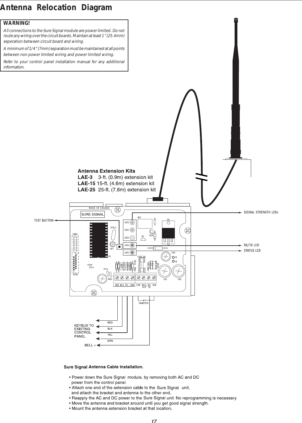
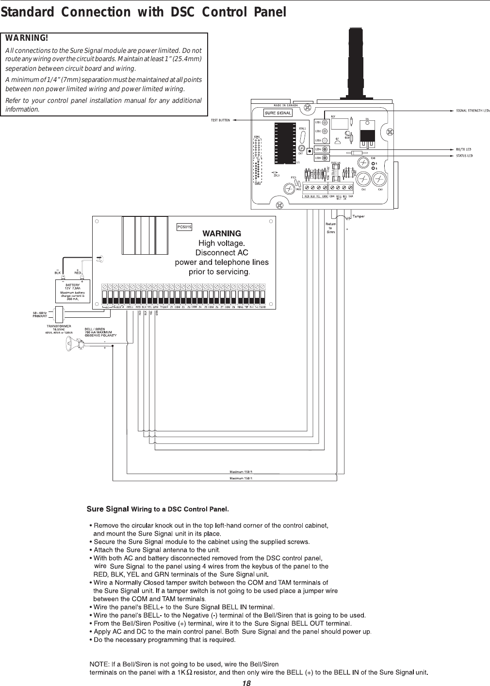
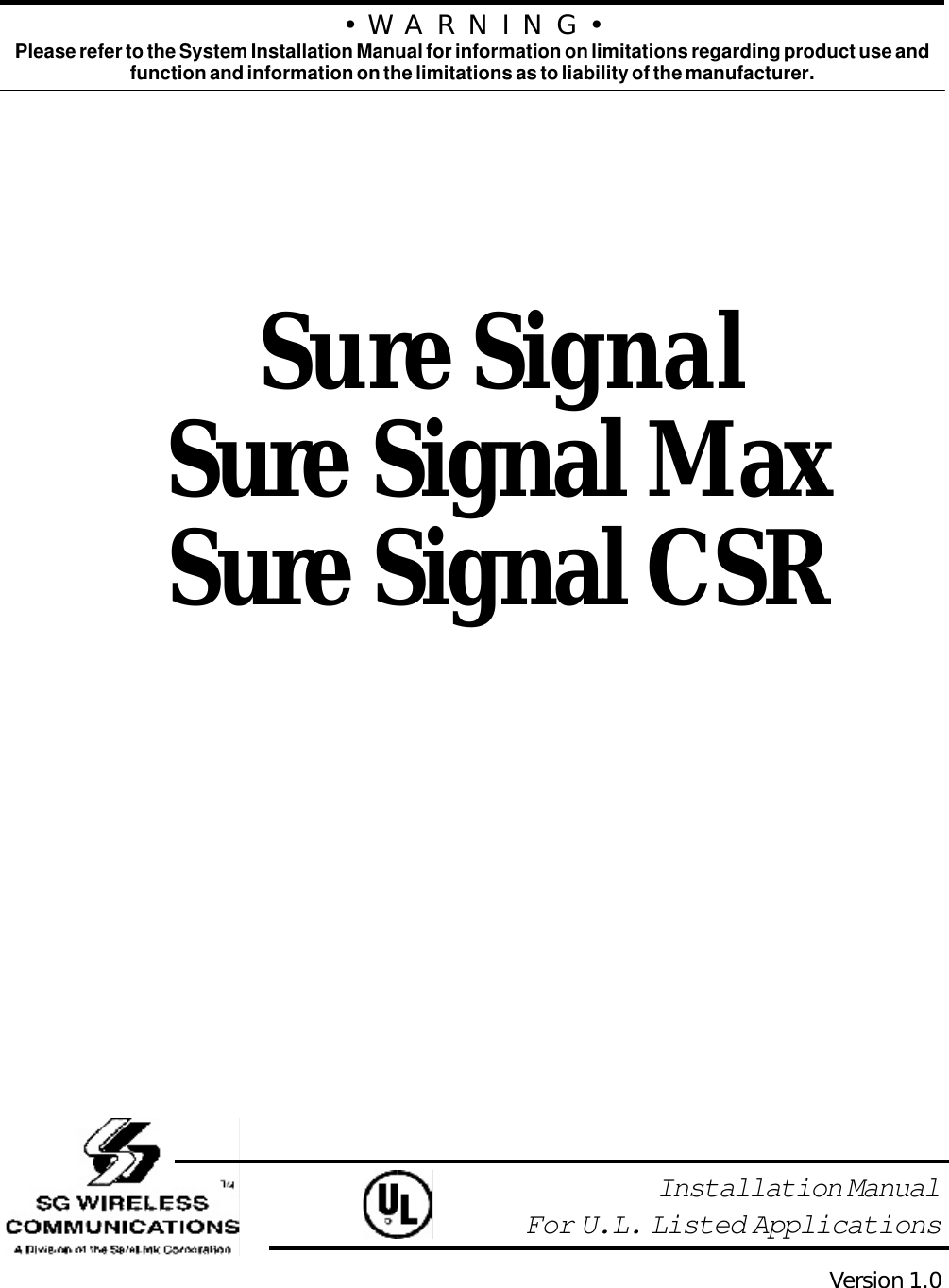
![4Enrolling the Sure Signal RadioBefore powering up the radio, information must be provided toConnect24 for the Sure Signal Radio. The radio information mustbe given to Connect24on the service request form. Once theservice has been set up by the provider, the installer will have toselect the appropriate provider (from the predefined list in thismanual) in the network connection selections section. Theinstaller must ensure that the Mailbox section is disabled. Boththe receiver radio and Sure Signal must be set up with thesame provider in order to function.When changing network providers, the subscription to theprevious network should be cancelled. Otherwise, Sure Signalwill remain connected to the previous network if it cannot findthe new network.Once the previous subscription is cancelled, the installer needs onlyto follow the enrollment procedure as described above.Relocating the AntennaIf a suitable location is not available for proper Mobitexcoverage, obtain an Antenna Extension Bracket kit from your SGWireless Communications supplier. Each kit contains an exten-sion cable, a mounting bracket, instructions, and all requiredhardware. Three lengths of extension cable are available:Extension Kit Length of cableLAE-3 3 feet (0.91 m)LAE-15 15 feet (4.57 m)LAE-25 25 feet (7.62 m)Only use the Extension Kits to extend the mounting range ofthe antenna. Do not cut or splice the extension cable. Themaximum distance between Sure Signal and the antenna is 25feet (7.62 m) as obtained by using the LAE-25 Extension Kit.Make sure the antenna is in a physically secured location toavoid tampering.Secure the TNC connector from the Exten-sion Kit to the mounting bracket, ensuring that the starwashers make solid electrical contact with the mountingbracket.Remove the antenna from the Sure Signal moduleand connect the extension cable to the TNC connector on themodule. Secure the antenna to the TNC connector mountedon the Extension Kit Mounting Bracket. Locate the mountingbracket and antenna away from possible sources of electricalinterference. Moving the antenna just a short distance willlikely be adequate. Temporarily secure the mounting bracketin the new location and proceed with testing. If the test issuccessful, permanently secure the mounting bracket andantenna at the new location.Note: 30cm must be kept between antenna and a person/Relocating the Sure SignalSince Sure Signal is a Keybus accessory, it is possible torelocate the module up to 1000 feet from the main controlpanel when the panel is not located in a good Mobitexcoverage area (a control panel installed in a vault forexample). When relocating the module, follow theses rules:•Maximum of 1000 feet from the main control. Keybus(Red, Black, Yellow, Green) from the panel to theSure Signal.•A UL1481 power supply 12V@1.5A must be used.•The power supply (AUX+) is connected to theSure Signal (BELL IN) terminal and the power supply(BLK) to the Sure Signal (COM) terminal.•The cabinet must be installed in a secure location andshould have a tamper circuit connected to theSure Signal (TAM and COM) terminals.Programming SectionsAll programming on Sure Signal is done in the installer’sprogramming mode. Refer to the control panel’s InstallationManual for instructions on how to enter installer’s program-ming. From installer’s programming, enter section [803] togo to Sure Signal programming sections.NOTE: Section [06], Option 1 (Radio Enable/Disable) mustbe ON before supervision of the module can occur.[01]-[05] Zone DefinitionThese sections must be programmed exactly the same as themain control panel. This allows Sure Signal to translateinformation sent along the Keybus and identify the proper event.[06] Configuration OptionsOption [1] Radio Enable/DisableOption [2] ULAA Supervision Enable/Disable. This optionmust be selected to disable ULAA supervision.Option [3] Standard SIA Test TX / RSSI and Status in Test TX[10] First Account Number4-digit hex entry.[11] Second Account Number4-digit hex entry.[15] First Receiver Man NumberFour 2-digit decimal entry.[16] Second Receiver Man NumberFour 2-digit decimal entry.Note: For 7-digit man numbers, the first digit must be 0.[20] Communicator Format Options2-digit entry.01 = Condensed SIA without account number02 = Condensed SIA with account numbers[21] Network Connection Selections2-digit entry.00 = No network selected01 = Connect to Cantel network02 = Connect to Ram/Ardus network03 = Connect to Ram/Aust network[22] Transmission OptionsThis section will enable sections of reporting codes.[23] Number of Attempts to Each Man3-digit entry (001-255).[24] Response Wait Time3-digit entry (001-255) × 10 seconds.[30]-[78] Individual Event - Transmission ToggleThese sections are used to determine if an event will betransmitted by Sure Signal. If ’00’ is entered, then that event willnot be transmitted. If ‘FF’ is programmed, then the event will betransmitted. ‘FF’ is the default value.](https://usermanual.wiki/Digital-Security-Controls/SURESIGNAL/User-Guide-137085-Page-8.png)
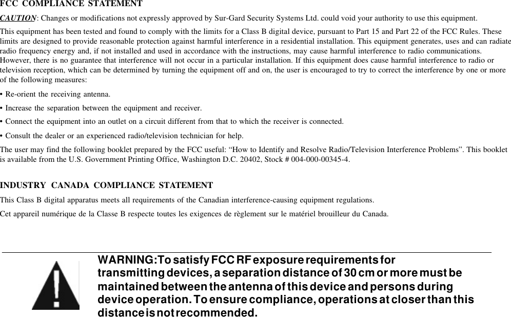
![5Activating Sure SignalBefore activating Sure Signal, ensure that the control panel iswired, programmed and operating properly. Make sure that theSure Signal transmitter is properly connected to the Keybus andto the bell positive circuit. When power is applied to thesystem, Sure Signal will perform self-diagnostics for a fewseconds, before giving visual feedback by indicating signalstrength on LED1, LED2 and LED3. A complete default ofthe Sure Signal module should always be performedbefore any other programming is done. Enter ‘00’ insection ‘99’ to perform the default.Transmitting and ReceivingLED4 on the Sure Signal module will blink once (1) toindicate the radio has transmitted an event. It will blink twice(2) to indicate that an acknowledgement has been receivedfrom the alarm central station. Sure Signal will not followTransmission Delay as programmed in Section [370] of thepanel. Events will be transmitted immediately.Test TransmissionsSure Signal will send test transmissions as they come across theKeybus. All of the programming for timed test transmissions isdone at the panel. When the test transmissions come across theKeybus, they will be transmitted as per SIA reporting codes(Appendix A).Sure Signal can also be set up for ULAA Listed systems. WhenULAA supervision is enabled (Section [06], bit 2OFF), Sure Signalis responsible for test transmission times. A test transmissionmust be sent every 30 minutes if the panel is disarmed, and every3 minutes if the panel is armed (either or both partitions on apartitioned system).There is also a Sure Signal test transmission switch (SW1)located on its printed circuit board. None of the testtransmissions are affected by transmission options (Section[803], Option [22]). They can only be enabled/disabled inthe Test Transmission Reporting Codes section (Section[803], Option [78]).Sure Signal Trouble SupervisionSure Signal automatically monitors its operation and indicatestrouble conditions by flashing LED5 on the circuit board. LED5normally flashes once every second when Sure Signal is onstandby (ready to transmit) mode. Troubles are indicated whenLED5 flashes more than once every second. Shown below is thenumber of flashes used to indicate each trouble condition in orderof importance:2, 6, 3, 4, 5, 1TABLE 1:Numberof flashes Function of flashes1Radio is operating normally2Radio is not connected or not responding3Network is not available4FTC (Failure to Communicate) 1 -MPAK Flag reason5FTC (Failure to Communicate) 2 -Radio reason6No number programmed for Man Number 1(Section [15])Sure Signal Trouble Shooting1. Check all wiring•Make sure all the Keybus connections are correct.•Make sure BELL+ is connected to the BELL IN of theSure Signal module.2. Check the LED5•Check number of flashes on LED5. If LED flashes morethan once every half second refer to TABLE 1.•6 flashes indicates no number programmed for ManNumber 1 (Section [15]).3. If intermittent failure to communicate is seen (5flashes), number of attempts (option 23) should beincreased to 10 and/or response wait time should beincreased to 60 seconds (option 24=006).4. If LED5 flashes once every half second, yet Sure Signaldoes not communicate, call SG Wireless Technical Supportat 1-888-623-7873 ext.1 or 416-665-0051 ext.1.5. Before contacting Technical Support, please have thefollowing information ready: MAN number of theSure Signal unit, ESN number of the Sure Signal unit andaccount number.](https://usermanual.wiki/Digital-Security-Controls/SURESIGNAL/User-Guide-137085-Page-9.png)
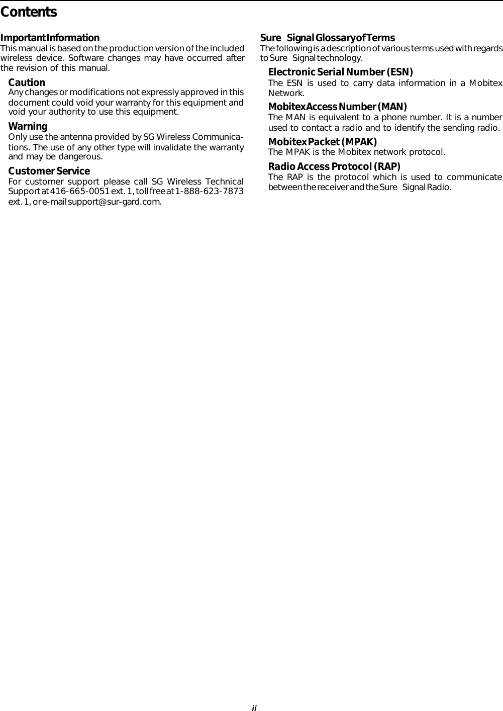
![6[803] Sure Signal Programming (PC5010/580/1555/5015)Zone Definitions00 Null Zone (No Alarm) 09 24 Hour Supervisory 18 24 Hour Sprinkler01 Delay 1 10 24 Hour Supervisory Buzzer 19 24 Hour Water02 Delay 2 11 24 Hour Burglary 20 24 Hour Freeze03 Instant 12 24 Hour Holdup 21 24 Hour Latching Tamper04 Interior 13 24 Hour Gas 22 Momentary Keyswitch Arm05 Interior, Stay-Away 14 24 Hour Heat 23 Maintained Keyswitch Arm06 Delay, Stay-Away 15 24 Hour Medical 24 LINKS Answer07 Delayed 24 Hour Fire (Hardwired) 16 24 Hour Panic 87 Delayed 24 Hour Fire (Wireless)08 Standard 24 Hour Fire (Hardwired) 17 24 Hour Emergency 88 Standard 24 Hour Fire (Wireless)[01] Zone 1-8 DefinitionsDefault Default00 I_____I_____I Zone 1 00 I_____I_____I Zone 500 I_____I_____I Zone 2 00 I_____I_____I Zone 600 I_____I_____I Zone 3 00 I_____I_____I Zone 700 I_____I_____I Zone 4 00 I_____I_____I Zone 8[02] Zone 9-16 Definitions00 I_____I_____I Zone 9 00 I_____I_____I Zone 1300 I_____I_____I Zone 10 00 I_____I_____I Zone 1400 I_____I_____I Zone 11 00 I_____I_____I Zone 1500 I_____I_____I Zone 12 00 I_____I_____I Zone 16[03] Zone 17-24 Definitions00 I_____I_____I Zone 17 00 I_____I_____I Zone 2100 I_____I_____I Zone 18 00 I_____I_____I Zone 2200 I_____I_____I Zone 19 00 I_____I_____I Zone 2300 I_____I_____I Zone 20 00 I_____I_____I Zone 24[04] Zone 25-32 Definitions00 I_____I_____I Zone 25 00 I_____I_____I Zone 2900 I_____I_____I Zone 26 00 I_____I_____I Zone 3000 I_____I_____I Zone 27 00 I_____I_____I Zone 3100 I_____I_____I Zone 28 00 I_____I_____I Zone 32[05] PGM2 Definition00 I_____I_____I If PGM2 is used as 2 Wire Smoke, Silent 24 Hour or Audible 24 Hour.[06] Sure Signal Configuration OptionsDefault Option ON Option OFFOFF I_____I Option 1 Radio is Enabled DisabledON I_____I Option 2 ULAA Supervision is Disabled EnabledOFF I_____I Option 3 Standard SIA RSS1 and status with TXI_____I Option 4 to 8 For Future Use[10] Sure Signal First Account NumberFF FF I_____I_____I - I_____I_____I (00 00 - FF FF)[11] Sure Signal Second Account NumberFF FF I_____I_____I - I_____I_____I (00 00 - FF FF)[15] First Receiver Man NumberFF FF FF FF I_____I_____I - I_____I_____I - I_____I_____I - I_____I_____IValid entries for all 2-digit sections (00-99) decimal. NOTE: For most applications, first digit is ‘0’.](https://usermanual.wiki/Digital-Security-Controls/SURESIGNAL/User-Guide-137085-Page-10.png)
![7[16] Second Receiver Man Number (four 2-digit entries)DefaultFF FF FF FF I_____I_____I - I_____I_____I - I_____I_____I - I_____I_____IValid entries for all 2-digit sections (00-99) decimal. NOTE: For most applications, first digit is ‘0’.[20] Communicator Format OptionsDefault02 I_____I_____I01 = Condensed SIA without transmitted account number02 = Condensed SIA with 4-digit account number[21] Network Connection SelectionsI_____I_____I00 = No network selected01 = Connect to Cantel network02 = Connect to Ram/Ardus network03 = Connect to Ram/Aust network[22] Transmission OptionsDefault Option ON Option OFFON I_____I Option 1 Alarms/Restorals DisabledON I_____I Option 2 Tampers/Restorals DisabledON I_____I Option 3 Zone Supervisory Alarms/Restorals DisabledON I_____I Option 4 Low Battery Alarms/Restorals DisabledOFF I_____I Option 5 Openings/Closings DisabledON I_____I Option 6 Maintenance Alarms/Restorals DisabledOFF I_____I Option 7 For future use DisabledOFF I_____I Option 8 For future use Disabled[23] Number of Attempts003 I_____I_____I_____I 001 – 255 (decimal)[24] Response Wait Time005 I_____I_____I_____I 001 – 255 (decimal, ×10 seconds)Note: Programming 000 in this section will be accepted as 001. (It will remain as 000 in the programming section.)](https://usermanual.wiki/Digital-Security-Controls/SURESIGNAL/User-Guide-137085-Page-11.png)
![8These are “ON” or “OFF” toggle optionsSections [30] to [78]: if ’00’ is entered, then that reporting code is disabled (“OFF”). If ‘FF’ is in the section,then the default reporting code is enabled (“ON”).[30] Alarm Reporting Codes, Zones 1-8Default DefaultFF I_____I_____I Zone 1 Alarm FF I_____I_____I Zone 5 AlarmFF I_____I_____I Zone 2 Alarm FF I_____I_____I Zone 6 AlarmFF I_____I_____I Zone 3 Alarm FF I_____I_____I Zone 7 AlarmFF I_____I_____I Zone 4 Alarm FF I_____I_____I Zone 8 Alarm[31] Alarm Reporting Codes, Zones 9-16FF I_____I_____I Zone 9 Alarm FF I_____I_____I Zone 13 AlarmFF I_____I_____I Zone 10 Alarm FF I_____I_____I Zone 14 AlarmFF I_____I_____I Zone 11 Alarm FF I_____I_____I Zone 15 AlarmFF I_____I_____I Zone 12 Alarm FF I_____I_____I Zone 16 Alarm[32] Alarm Reporting Codes, Zones 17-24FF I_____I_____I Zone 17 Alarm FF I_____I_____I Zone 21 AlarmFF I_____I_____I Zone 18 Alarm FF I_____I_____I Zone 22 AlarmFF I_____I_____I Zone 19 Alarm FF I_____I_____I Zone 23 AlarmFF I_____I_____I Zone 20 Alarm FF I_____I_____I Zone 24 Alarm[33] Alarm Reporting Codes, Zones 25-32FF I_____I_____I Zone 25 Alarm FF I_____I_____I Zone 29 AlarmFF I_____I_____I Zone 26 Alarm FF I_____I_____I Zone 30 AlarmFF I_____I_____I Zone 27 Alarm FF I_____I_____I Zone 31 AlarmFF I_____I_____I Zone 28 Alarm FF I_____I_____I Zone 32 Alarm[34] Alarm Restoral Reporting Codes, Zones 1-8Default DefaultFF I_____I_____I Zone 1 Alarm Restoral FF I_____I_____I Zone 5 Alarm RestoralFF I_____I_____I Zone 2 Alarm Restoral FF I_____I_____I Zone 6 Alarm RestoralFF I_____I_____I Zone 3 Alarm Restoral FF I_____I_____I Zone 7 Alarm RestoralFF I_____I_____I Zone 4 Alarm Restoral FF I_____I_____I Zone 8 Alarm Restoral[35] Alarm Restoral Reporting Codes, Zones 9-16FF I_____I_____I Zone 9 Alarm Restoral FF I_____I_____I Zone 13 Alarm RestoralFF I_____I_____I Zone 10 Alarm Restoral FF I_____I_____I Zone 14 Alarm RestoralFF I_____I_____I Zone 11 Alarm Restoral FF I_____I_____I Zone 15 Alarm RestoralFF I_____I_____I Zone 12 Alarm Restoral FF I_____I_____I Zone 16 Alarm Restoral[36] Alarm Restoral Reporting Codes, Zones 17-24FF I_____I_____I Zone 17 Alarm Restoral FF I_____I_____I Zone 21 Alarm RestoralFF I_____I_____I Zone 18 Alarm Restoral FF I_____I_____I Zone 22 Alarm RestoralFF I_____I_____I Zone 19 Alarm Restoral FF I_____I_____I Zone 23 Alarm RestoralFF I_____I_____I Zone 20 Alarm Restoral FF I_____I_____I Zone 24 Alarm Restoral[37] Alarm Restoral Reporting Codes, Zones 25-32FF I_____I_____I Zone 25 Alarm Restoral FF I_____I_____I Zone 29 Alarm RestoralFF I_____I_____I Zone 26 Alarm Restoral FF I_____I_____I Zone 30 Alarm RestoralFF I_____I_____I Zone 27 Alarm Restoral FF I_____I_____I Zone 31 Alarm RestoralFF I_____I_____I Zone 28 Alarm Restoral FF I_____I_____I Zone 32 Alarm Restoral](https://usermanual.wiki/Digital-Security-Controls/SURESIGNAL/User-Guide-137085-Page-12.png)
![9[38] Miscellaneous Alarm Reporting CodesFF I_____I_____I Duress Alarm FF I_____I_____I Zone Expander Supervisory AlarmFF I_____I_____I Opening After Alarm FF I_____I_____I Zone Expander Supervisory RestoralFF I_____I_____I Recent Closing FF I_____I_____I Cross Zoning (Burglary Verified) Alarm[39] Priority Alarm and Restoral Reporting CodesFF I_____I_____I Keypad [F]ire Alarm FF I_____I_____I Keypad [F]ire RestoralFF I_____I_____I Keypad [A]uxiliary Alarm FF I_____I_____I Keypad [A]uxiliary RestoralFF I_____I_____I Keypad [P]anic Alarm FF I_____I_____I Keypad [P]anic RestoralFF I_____I_____I PGM2 Alarm FF I_____I_____I PGM2 Restoral[40] Tamper Reporting Codes, Zones 1-8FF I_____I_____I Zone 1 Tamper FF I_____I_____I Zone 5 TamperFF I_____I_____I Zone 2 Tamper FF I_____I_____I Zone 6 TamperFF I_____I_____I Zone 3 Tamper FF I_____I_____I Zone 7 TamperFF I_____I_____I Zone 4 Tamper FF I_____I_____I Zone 8 Tamper[41] Tamper Reporting Codes, Zones 9-16FF I_____I_____I Zone 9 Tamper FF I_____I_____I Zone 13 TamperFF I_____I_____I Zone 10 Tamper FF I_____I_____I Zone 14 TamperFF I_____I_____I Zone 11 Tamper FF I_____I_____I Zone 15 TamperFF I_____I_____I Zone 12 Tamper FF I_____I_____I Zone 16 Tamper[42] Tamper Reporting Codes, Zones 17-24FF I_____I_____I Zone 17 Tamper FF I_____I_____I Zone 21 TamperFF I_____I_____I Zone 18 Tamper FF I_____I_____I Zone 22 TamperFF I_____I_____I Zone 19 Tamper FF I_____I_____I Zone 23 TamperFF I_____I_____I Zone 20 Tamper FF I_____I_____I Zone 24 Tamper[43] Tamper Reporting Codes, Zones 25-32Default DefaultFF I_____I_____I Zone 25 Tamper FF I_____I_____I Zone 29 TamperFF I_____I_____I Zone 26 Tamper FF I_____I_____I Zone 30 TamperFF I_____I_____I Zone 27 Tamper FF I_____I_____I Zone 31 TamperFF I_____I_____I Zone 28 Tamper FF I_____I_____I Zone 32 Tamper[44] Tamper Restoral Reporting Codes, Zones 1-8FF I_____I_____I Zone 1 Tamper Restoral FF I_____I_____I Zone 5 Tamper RestoralFF I_____I_____I Zone 2 Tamper Restoral FF I_____I_____I Zone 6 Tamper RestoralFF I_____I_____I Zone 3 Tamper Restoral FF I_____I_____I Zone 7 Tamper RestoralFF I_____I_____I Zone 4 Tamper Restoral FF I_____I_____I Zone 8 Tamper Restoral[45] Tamper Restoral Reporting Codes, Zones 9-16FF I_____I_____I Zone 9 Tamper Restoral FF I_____I_____I Zone 13 Tamper RestoralFF I_____I_____I Zone 10 Tamper Restoral FF I_____I_____I Zone 14 Tamper RestoralFF I_____I_____I Zone 11 Tamper Restoral FF I_____I_____I Zone 15 Tamper RestoralFF I_____I_____I Zone 12 Tamper Restoral FF I_____I_____I Zone 16 Tamper Restoral[46] Tamper Restoral Reporting Codes, Zones 17-24FF I_____I_____I Zone 17 Tamper Restoral FF I_____I_____I Zone 21 Tamper RestoralFF I_____I_____I Zone 18 Tamper Restoral FF I_____I_____I Zone 22 Tamper RestoralFF I_____I_____I Zone 19 Tamper Restoral FF I_____I_____I Zone 23 Tamper RestoralFF I_____I_____I Zone 20 Tamper Restoral FF I_____I_____I Zone 24 Tamper Restoral](https://usermanual.wiki/Digital-Security-Controls/SURESIGNAL/User-Guide-137085-Page-13.png)
![10[47] Tamper Restoral Reporting Codes, Zones 25-32FF I_____I_____I Zone 25 Tamper Restoral FF I_____I_____I Zone 29 Tamper RestoralFF I_____I_____I Zone 26 Tamper Restoral FF I_____I_____I Zone 30 Tamper RestoralFF I_____I_____I Zone 27 Tamper Restoral FF I_____I_____I Zone 31 Tamper RestoralFF I_____I_____I Zone 28 Tamper Restoral FF I_____I_____I Zone 32 Tamper Restoral[48] Miscellaneous Tamper Reporting CodesFF I_____I_____I General System Tamper FF I_____I_____I Keypad LockoutFF I_____I_____I General System Tamper Rest.[49] Supervisory Reporting Codes, Zones 1-8FF I_____I_____I Zone 1 Supervisory FF I_____I_____I Zone 5 SupervisoryFF I_____I_____I Zone 2 Supervisory FF I_____I_____I Zone 6 SupervisoryFF I_____I_____I Zone 3 Supervisory FF I_____I_____I Zone 7 SupervisoryFF I_____I_____I Zone 4 Supervisory FF I_____I_____I Zone 8 Supervisory[50] Supervisory Reporting Codes, Zones 9-16FF I_____I_____I Zone 9 Supervisory FF I_____I_____I Zone 13 SupervisoryFF I_____I_____I Zone 10 Supervisory FF I_____I_____I Zone 14 SupervisoryFF I_____I_____I Zone 11 Supervisory FF I_____I_____I Zone 15 SupervisoryFF I_____I_____I Zone 12 Supervisory FF I_____I_____I Zone 16 Supervisory[51] Supervisory Reporting Codes, Zones 17-24FF I_____I_____I Zone 17 Supervisory FF I_____I_____I Zone 21 SupervisoryFF I_____I_____I Zone 18 Supervisory FF I_____I_____I Zone 22 SupervisoryFF I_____I_____I Zone 19 Supervisory FF I_____I_____I Zone 23 SupervisoryFF I_____I_____I Zone 20 Supervisory FF I_____I_____I Zone 24 Supervisory[52] Supervisory Reporting Codes, Zones 25-32Default DefaultFF I_____I_____I Zone 25 Supervisory FF I_____I_____I Zone 29 SupervisoryFF I_____I_____I Zone 26 Supervisory FF I_____I_____I Zone 30 SupervisoryFF I_____I_____I Zone 27 Supervisory FF I_____I_____I Zone 31 SupervisoryFF I_____I_____I Zone 28 Supervisory FF I_____I_____I Zone 32 Supervisory[53] Supervisory Restoral Reporting Codes, Zones 1-8FF I_____I_____I Zone 1 Supervisory Restoral FF I_____I_____I Zone 5 Supervisory RestoralFF I_____I_____I Zone 2 Supervisory Restoral FF I_____I_____I Zone 6 Supervisory RestoralFF I_____I_____I Zone 3 Supervisory Restoral FF I_____I_____I Zone 7 Supervisory RestoralFF I_____I_____I Zone 4 Supervisory Restoral FF I_____I_____I Zone 8 Supervisory Restoral[54] Supervisory Restoral Reporting Codes, Zones 9-16FF I_____I_____I Zone 9 Supervisory Restoral FF I_____I_____I Zone 13 Supervisory RestoralFF I_____I_____I Zone 10 Supervisory Restoral FF I_____I_____I Zone 14 Supervisory RestoralFF I_____I_____I Zone 11 Supervisory Restoral FF I_____I_____I Zone 15 Supervisory RestoralFF I_____I_____I Zone 12 Supervisory Restoral FF I_____I_____I Zone 16 Supervisory Restoral[55] Supervisory Restoral Reporting Codes, Zones 17-24FF I_____I_____I Zone 17 Supervisory Restoral FF I_____I_____I Zone 21 Supervisory RestoralFF I_____I_____I Zone 18 Supervisory Restoral FF I_____I_____I Zone 22 Supervisory RestoralFF I_____I_____I Zone 19 Supervisory Restoral FF I_____I_____I Zone 23 Supervisory RestoralFF I_____I_____I Zone 20 Supervisory Restoral FF I_____I_____I Zone 24 Supervisory Restoral](https://usermanual.wiki/Digital-Security-Controls/SURESIGNAL/User-Guide-137085-Page-14.png)
![11[56] Supervisory Restoral Reporting Codes, Zones 25-32FF I_____I_____I Zone 25 Supervisory Restoral FF I_____I_____I Zone 29 Supervisory RestoralFF I_____I_____I Zone 26 Supervisory Restoral FF I_____I_____I Zone 30 Supervisory RestoralFF I_____I_____I Zone 27 Supervisory Restoral FF I_____I_____I Zone 31 Supervisory RestoralFF I_____I_____I Zone 28 Supervisory Restoral FF I_____I_____I Zone 32 Supervisory Restoral[57] Low Battery Reporting Codes, Zones 1-8FF I_____I_____I Zone 1 Low Battery FF I_____I_____I Zone 5 Low BatteryFF I_____I_____I Zone 2 Low Battery FF I_____I_____I Zone 6 Low BatteryFF I_____I_____I Zone 3 Low Battery FF I_____I_____I Zone 7 Low BatteryFF I_____I_____I Zone 4 Low Battery FF I_____I_____I Zone 8 Low Battery[58] Low Battery Reporting Codes, Zones 9-16FF I_____I_____I Zone 9 Low Battery FF I_____I_____I Zone 13 Low BatteryFF I_____I_____I Zone 10 Low Battery FF I_____I_____I Zone 14 Low BatteryFF I_____I_____I Zone 11 Low Battery FF I_____I_____I Zone 15 Low BatteryFF I_____I_____I Zone 12 Low Battery FF I_____I_____I Zone 16 Low Battery[59] Low Battery Reporting Codes, Zones 17-24FF I_____I_____I Zone 17 Low Battery FF I_____I_____I Zone 21 Low BatteryFF I_____I_____I Zone 18 Low Battery FF I_____I_____I Zone 22 Low BatteryFF I_____I_____I Zone 19 Low Battery FF I_____I_____I Zone 23 Low BatteryFF I_____I_____I Zone 20 Low Battery FF I_____I_____I Zone 24 Low Battery[60] Low Battery Reporting Codes, Zones 25-32FF I_____I_____I Zone 25 Low Battery FF I_____I_____I Zone 29 Low BatteryFF I_____I_____I Zone 26 Low Battery FF I_____I_____I Zone 30 Low BatteryFF I_____I_____I Zone 27 Low Battery FF I_____I_____I Zone 31 Low BatteryFF I_____I_____I Zone 28 Low Battery FF I_____I_____I Zone 32 Low Battery[61] Low Battery Restoral Reporting Codes, Zones 1-8Default DefaultFF I_____I_____I Zone 1 Low Battery Restoral FF I_____I_____I Zone 5 Low Battery RestoralFF I_____I_____I Zone 2 Low Battery Restoral FF I_____I_____I Zone 6 Low Battery RestoralFF I_____I_____I Zone 3 Low Battery Restoral FF I_____I_____I Zone 7 Low Battery RestoralFF I_____I_____I Zone 4 Low Battery Restoral FF I_____I_____I Zone 8 Low Battery Restoral[62] Low Battery Restoral Reporting Codes, Zones 9-16FF I_____I_____I Zone 9 Low Battery Restoral FF I_____I_____I Zone 13 Low Battery RestoralFF I_____I_____I Zone 10 Low Battery Restoral FF I_____I_____I Zone 14 Low Battery RestoralFF I_____I_____I Zone 11 Low Battery Restoral FF I_____I_____I Zone 15 Low Battery RestoralFF I_____I_____I Zone 12 Low Battery Restoral FF I_____I_____I Zone 16 Low Battery Restoral[63] Low Battery Restoral Reporting Codes, Zones 17-24FF I_____I_____I Zone 17 Low Battery Restoral FF I_____I_____I Zone 21 Low Battery RestoralFF I_____I_____I Zone 18 Low Battery Restoral FF I_____I_____I Zone 22 Low Battery RestoralFF I_____I_____I Zone 19 Low Battery Restoral FF I_____I_____I Zone 23 Low Battery RestoralFF I_____I_____I Zone 20 Low Battery Restoral FF I_____I_____I Zone 24 Low Battery Restoral[64] Low Battery Restoral Reporting Codes, Zones 25-32FF I_____I_____I Zone 25 Low Battery Restoral FF I_____I_____I Zone 29 Low Battery RestoralFF I_____I_____I Zone 26 Low Battery Restoral FF I_____I_____I Zone 30 Low Battery RestoralFF I_____I_____I Zone 27 Low Battery Restoral FF I_____I_____I Zone 31 Low Battery RestoralFF I_____I_____I Zone 28 Low Battery Restoral FF I_____I_____I Zone 32 Low Battery Restoral](https://usermanual.wiki/Digital-Security-Controls/SURESIGNAL/User-Guide-137085-Page-15.png)
![12[65] Closing (Arming) Reporting Codes, Access Codes 1-8FF I_____I_____I Closing By Access Code 1 FF I_____I_____I Closing By Access Code 5FF I_____I_____I Closing By Access Code 2 FF I_____I_____I Closing By Access Code 6FF I_____I_____I Closing By Access Code 3 FF I_____I_____I Closing By Access Code 7FF I_____I_____I Closing By Access Code 4 FF I_____I_____I Closing By Access Code 8[66] Closing (Arming) Reporting Codes, Access Codes 9-16FF I_____I_____I Closing By Access Code 9 FF I_____I_____I Closing By Access Code 13FF I_____I_____I Closing By Access Code 10 FF I_____I_____I Closing By Access Code 14FF I_____I_____I Closing By Access Code 11 FF I_____I_____I Closing By Access Code 15FF I_____I_____I Closing By Access Code 12 FF I_____I_____I Closing By Access Code 16[67] Closing (Arming) Reporting Codes, Access Codes 17-24FF I_____I_____I Closing By Access Code 17 FF I_____I_____I Closing By Access Code 21FF I_____I_____I Closing By Access Code 18 FF I_____I_____I Closing By Access Code 22FF I_____I_____I Closing By Access Code 19 FF I_____I_____I Closing By Access Code 23FF I_____I_____I Closing By Access Code 20 FF I_____I_____I Closing By Access Code 24[68] Closing (Arming) Reporting Codes, Access Codes 25-32FF I_____I_____I Closing By Access Code 25 FF I_____I_____I Closing By Access Code 29FF I_____I_____I Closing By Access Code 26 FF I_____I_____I Closing By Access Code 30FF I_____I_____I Closing By Access Code 27 FF I_____I_____I Closing By Access Code 31FF I_____I_____I Closing By Access Code 28 FF I_____I_____I Closing By Access Code 32[69] Miscellaneous Closing (Arming) Reporting CodesFF I_____I_____I Closing by Duress Code 33 FF I_____I_____I Closing by System Code 42FF I_____I_____I Closing by Duress Code 34 FF I_____I_____I Partial ClosingFF I_____I_____I Closing by System Code 40 FF I_____I_____I Special ClosingFF I_____I_____I Closing by System Code 41[70] Opening (Disarming) Reporting Codes, Access Codes 1-8Default DefaultFF I_____I_____I Opening By Access Code 1 FF I_____I_____I Opening By Access Code 5FF I_____I_____I Opening By Access Code 2 FF I_____I_____I Opening By Access Code 6FF I_____I_____I Opening By Access Code 3 FF I_____I_____I Opening By Access Code 7FF I_____I_____I Opening By Access Code 4 FF I_____I_____I Opening By Access Code 8[71] Opening (Disarming) Reporting Codes, Access Codes 9-16FF I_____I_____I Opening By Access Code 9 FF I_____I_____I Opening By Access Code 13FF I_____I_____I Opening By Access Code 10 FF I_____I_____I Opening By Access Code 14FF I_____I_____I Opening By Access Code 11 FF I_____I_____I Opening By Access Code 15FF I_____I_____I Opening By Access Code 12 FF I_____I_____I Opening By Access Code 16[72] Opening (Disarming) Reporting Codes, Access Codes 17-24FF I_____I_____I Opening By Access Code 17 FF I_____I_____I Opening By Access Code 21FF I_____I_____I Opening By Access Code 18 FF I_____I_____I Opening By Access Code 22FF I_____I_____I Opening By Access Code 19 FF I_____I_____I Opening By Access Code 23FF I_____I_____I Opening By Access Code 20 FF I_____I_____I Opening By Access Code 24[73] Opening (Disarming) Reporting Codes, Access Codes 25-32FF I_____I_____I Opening By Access Code 25 FF I_____I_____I Opening By Access Code 29FF I_____I_____I Opening By Access Code 26 FF I_____I_____I Opening By Access Code 30FF I_____I_____I Opening By Access Code 27 FF I_____I_____I Opening By Access Code 31FF I_____I_____I Opening By Access Code 28 FF I_____I_____I Opening By Access Code 32](https://usermanual.wiki/Digital-Security-Controls/SURESIGNAL/User-Guide-137085-Page-16.png)
![13[74] Miscellaneous Opening (Disarming) Reporting CodesFF I_____I_____I Opening by Duress Code 33 FF I_____I_____I Opening by System Code 42FF I_____I_____I Opening by Duress Code 34 FF I_____I_____I Auto Arm CancellationFF I_____I_____I Opening by System Code 40 FF I_____I_____I Special OpeningFF I_____I_____I Opening by System Code 41[75] Maintenance Alarm Reporting CodesFF I_____I_____I Battery Trouble Alarm FF I_____I_____I Auxiliary Power Supply Trouble AlarmFF I_____I_____I AC Failure Trouble Alarm FF I_____I_____I TLM Trouble CodeFF I_____I_____I Bell Circuit Trouble Alarm FF I_____I_____I General System TroubleFF I_____I_____I Fire Trouble Alarm FF I_____I_____I General System Supervisory[76] Maintenance Restoral Reporting CodesFF I_____I_____I Battery Trouble Restoral FF I_____I_____I Auxiliary Power Supply Trouble RestoralFF I_____I_____I AC Failure Trouble Restoral FF I_____I_____I TLM RestoralFF I_____I_____I Bell Circuit Trouble Restoral FF I_____I_____I General System Trouble RestoreFF I_____I_____I Fire Trouble Restoral FF I_____I_____I General System Supervisory Restore[77] Miscellaneous Maintenance Reporting CodesFF I_____I_____I Phone #1 FTC FF I_____I_____I Event Buffer 75% FullFF I_____I_____I Phone #2 FTC FF I_____I_____I DLS Lead INFF I_____I_____I Phone #1 FTC Restore FF I_____I_____I DLS Lead OUTFF I_____I_____I Phone #2 FTC Restore FF I_____I_____I Delinquency Reporting Code[78] Test Transmission Reporting CodesFF I_____I_____I Periodic Test Transmission FF I_____I_____I Mobitex Test TX CodeFF I_____I_____I System Test[99] Section [99] is for software defaulting of Sure Signal80 I_____I_____IEntering 00 will cause a software default of Sure Signal. Entering 01-FF will cause restart of Sure Signal. Entering any othervalue will not cause a default or a restart.[993] Inst. CodeRestore Sure Signal to factory default programming.Note: Sure Signal must be defaulted if it is connected to PC5010 version 1.00.](https://usermanual.wiki/Digital-Security-Controls/SURESIGNAL/User-Guide-137085-Page-17.png)
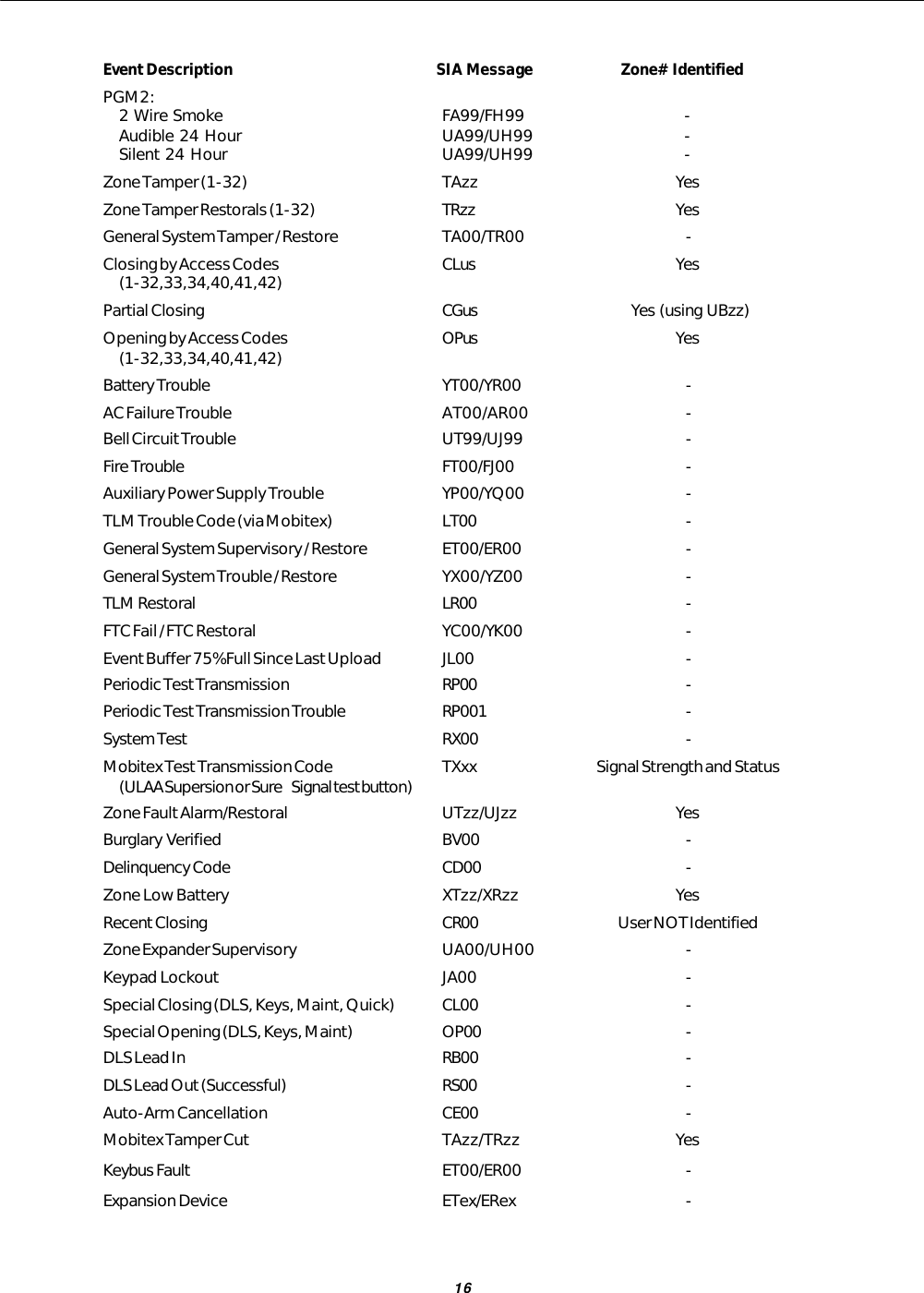
![15Appendix A - SIA Reporting codesSIA Communication FormatThe SIA communication format used in this product follows the Level 2 specifications of the SIA Digital Communication Standard- February 1993. This format will send the Account Code along with its data transmission. Below are the Zone Alarms & AlarmRestores (Zones 01-32) as well as any additional codes that can be transmitted:Terms Code Description—..........................................Not usedzz ..........................................Zone #us ..........................................User #ln ...........................................Lineex ..........................................Expander #xx...........................................RSS and statusAlarms Event Description SIA Message Zone# IdentifiedNull Zone (Not used) - -Delay 1 BAzz/BHzz YesDelay 2 BAzz/BHzz YesInstant BAzz/BHzz YesInterior BAzz/BHzz YesDelay H.A. BAzz/BHzz YesInterior H.A. BAzz/BHzz Yes24 Hr Burglary BAzz/BHzz YesStandard Fire FAzz/FHzz YesDelayed Fire FAzz/FHzz Yes24 Hour Supervisory UAzz/UHzz Yes24 Hr Supervisory Buzzer UAzz/UHzz Yes24 Hr Supervisory USzz/URzz Yes24 Hr Medical MAzz/MHzz Yes24 Hr Panic PAzz/PHzz Yes24 Hr Hold-up HAzz/HHzz Yes24 Hr Gas GAzz/GHzz Yes24 Hr Heat KAzz/KHzz Yes24 Hr Emergency QAzz/QHzz Yes24 Hr Sprinkler SAzz/SHzz Yes24 Hr Water WAzz/WHzz Yes24 Hr Freeze ZAzz/ZHzz Yes24 Hr Latching Tamper BAzz/BHzz YesDuress Alarm HA00 -Opening After Alarm OR00 -Keypad [F]ire FAzz/FHzz YesKeypad [A]uxiliary MAzz/MHzz YesKeypad [P]anic PAzz/PHzz Yes](https://usermanual.wiki/Digital-Security-Controls/SURESIGNAL/User-Guide-137085-Page-19.png)