Digital Security Controls SURESIGNAL SURE SIGNAL, SURE SIGNAL MAX & SURE SIGNAL CSR User Manual SG Sure Signal Installation Manual
Digital Security Controls Ltd. SURE SIGNAL, SURE SIGNAL MAX & SURE SIGNAL CSR SG Sure Signal Installation Manual
SG Sure Signal Installation Manual

• W A R N I N G •
Please refer to the System Installation Manual for information on limitations regarding product use and
function and information on the limitations as to liability of the manufacturer.
Sure Signal
Sure Signal Max
Sure Signal CSR
Installation Manual
For U.L. Listed Applications
Version 1.0

FCC COMPLIANCE STATEMENT
CAUTION: Changes or modifications not expressly approved by Sur-Gard Security Systems Ltd. could void your authority to use this equipment.
This equipment has been tested and found to comply with the limits for a Class B digital device, pursuant to Part 15 and Part 22 of the FCC Rules. These
limits are designed to provide reasonable protection against harmful interference in a residential installation. This equipment generates, uses and can radiate
radio frequency energy and, if not installed and used in accordance with the instructions, may cause harmful interference to radio communications.
However, there is no guarantee that interference will not occur in a particular installation. If this equipment does cause harmful interference to radio or
television reception, which can be determined by turning the equipment off and on, the user is encouraged to try to correct the interference by one or more
of the following measures:
•Re-orient the receiving antenna.
•Increase the separation between the equipment and receiver.
•Connect the equipment into an outlet on a circuit different from that to which the receiver is connected.
•Consult the dealer or an experienced radio/television technician for help.
The user may find the following booklet prepared by the FCC useful: “How to Identify and Resolve Radio/Television Interference Problems”. This booklet
is available from the U.S. Government Printing Office, Washington D.C. 20402, Stock # 004-000-00345-4.
INDUSTRY CANADA COMPLIANCE STATEMENT
This Class B digital apparatus meets all requirements of the Canadian interference-causing equipment regulations.
Cet appareil numérique de la Classe B respecte toutes les exigences de règlement sur le matériel brouilleur du Canada.
WARNING:To satisfy FCC RF exposure requirements for
transmitting devices, a separation distance of 30 cm or more must be
maintained between the antenna of this device and persons during
device operation. To ensure compliance, operations at closer than this
distance is not recommended.

Table of Contents
Programming Sections 4
[01]-[05] Zone Definition..................................................... 4
[06] Configuration Options.................................................. 4
[10] First Account Number .................................................. 4
[11] Second Account Number............................................. 4
[15] First Receiver Man Number .......................................... 4
[16] Second Receiver Man Number ..................................... 4
[20] Communicator Format Options ................................... 4
[21] Network Connection Selections................................... 4
[22] Transmission Options................................................... 4
[23] Number of Attempts to Each Man ............................... 4
[24] Response Wait Time ..................................................... 4
[30]-[78] Individual Event - Transmission Toggle................ 4
Activating the Sure Signal 5
Transmitting and Receiving.................................................. 5
Test Transmissions ............................................................... 5
Sure Signal Trouble Supervision 5
Sure Signal Trouble Shooting 5
[803] Sure Signal Programming (PC5010/580/1555/5015) 6
For Your Records 14
Appendix A – SIA Reporting Codes 15
Antenna Relocation Diagram 17
Standard Connection with DSC Control Panel 18
Limited Warranty/How to Contact Us Inside Back
Contents ii
Important Information...........................................................ii
Sure Signal Glossary of Terms..................................................ii
Introducing the Sure Signal 1
Specifications....................................................................... 1
Antenna ............................................................................... 1
RF Power Output .................................................................. 1
Power Supply ....................................................................... 1
Dimension ............................................................................ 1
Weight ................................................................................. 1
How the Sure Signal Works 1
Installation 2
Mounting the Sure Signal..................................................... 2
Mounting the Antenna ......................................................... 2
Wiring Connections.............................................................. 2
Keybus Connection............................................................... 2
Bell IN Terminal.................................................................... 2
Bell OUT Terminal ................................................................ 2
Tamper Terminal .................................................................. 2
Secure Installation................................................................ 2
UL Requirements .................................................................. 2
Connection Diagram 3
Enrolling the Sure Signal Radio 4
Relocating the Antenna 4
Relocating the Sure Signal 4
i

Contents
Important Information
This manual is based on the production version of the included
wireless device. Software changes may have occurred after
the revision of this manual.
Caution
Any changes or modifications not expressly approved in this
document could void your warranty for this equipment and
void your authority to use this equipment.
Warning
Only use the antenna provided by SG Wireless Communica-
tions. The use of any other type will invalidate the warranty
and may be dangerous.
Customer Service
For customer support please call SG Wireless Technical
Support at 416-665-0051 ext. 1, toll free at 1-888-623-7873
ext. 1, or e-mail support@sur-gard.com.
Sure Signal Glossary of Terms
The following is a description of various terms used with regards
to Sure Signal technology.
Electronic Serial Number (ESN)
The ESN is used to carry data information in a Mobitex
Network.
Mobitex Access Number (MAN)
The MAN is equivalent to a phone number. It is a number
used to contact a radio and to identify the sending radio.
Mobitex Packet (MPAK)
The MPAK is the Mobitex network protocol.
Radio Access Protocol (RAP)
The RAP is the protocol which is used to communicate
between the receiver and the Sure Signal Radio.
ii
1
Introducing the Sure Signal
Sure Signal offers a new wireless communication method for the
transmission of event information using the Mobitex service.
Events are transmitted from Sure Signal via the Mobitex network
to the Sure Signal CSR at the central station in a fast, reliable
manner. Sure Signal has been designed for simple and straightfor-
ward installation. Using the Keybus technology, wiring connec-
tions are made directly between the Sure Signal transceiver and the
security control panel.
Specifications
Compatible Control Panels
•DSC PC5010 software version v1.XX; v2.02
•DSC PC1555 software version v2.XX
•DSC PC580 software version v2.XX
•DSC PC5015 software version v1.XX; v2.2X
Communication Method
•Mobitex Network
Simultaneous Communications
•The system can be used as the sole method of
communication to the monitoring station or as a second
transmission path in addition to the standard land line.
Please contact your monitoring station on
dual signal communication.For UL Listed applications the
land line should be the primary communication channel
and the RF way should be the secondary communication
channel.
Antenna
•3 dB gain, TNC Connector
•Extension kits available:
LAE-3: 3-foot Antenna Kit for Sure Signal
LAE-15:15-foot Antenna Kit for Sure Signal
LAE-25:25-foot Antenna Kit for Sure Signal
RF Power Output
•2.0 watts maximum
Power Supply
•12 VDC @30mA, from panel Keybus, DSC Keybus
control panel required
•12 VDC, from bell circuit
Current in standby 90mA
Current when receiving 135mA
Current when transmitting 1.3A
Dimension
•3.5" x 4.6" x 1.8" (85 mm x 115 mm x 45 mm)
Weight
•0.5 lbs. (0.2 kg)
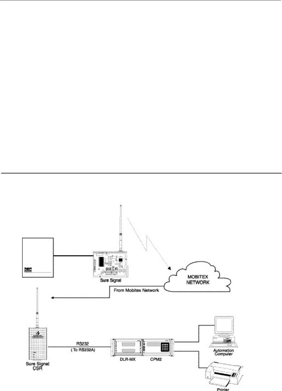
How Sure Signal Works
Sure Signal communicates using the Mobitex Digital Net-
work. Signals are sent to the Mobitex Network and then
forwarded to the central station. For every transmission sent
to the receiver, there will be an acknowledgment transmis-
sion sent back to the Sure Signal radio. For transmission
sequence see the drawing below:
2
Installation
Sure Signal unit is also suggested.
It is mandatory that the power be removed from the
system before any wiring changes are performed on the
Sure Signal module. Neglecting to do so will result in
damage to the radio modem.
Mounting the Sure Signal
Sure Signal can be mounted in the upper right hand corner of the
panel’s cabinet through the knock out. The Sure Signal case attaches
to the panel’s cabinet through the use of clips and two screws.
Mounting the Antenna
NOTE: The antenna should always be attached to the
Sure Signal unit for proper operation. The unit will not func-
tion properly if the antenna is not installed. Also note
the 30cm distance.
The antenna attaches to the TNC connector of the Sure Signal
module. The antenna should be mounted as high above ground
level as possible while at the same time taking care not to place
the antenna under a Radio frequency shield of any kind. For
example do not mount the antenna directly below a metal roofing
overhang. Sure Signal functions best when installed in an unob-
structed “line of sight” to the Mobitex base station. The antenna
should be located so that one of the two green LEDs is lit (LED1
or LED2).
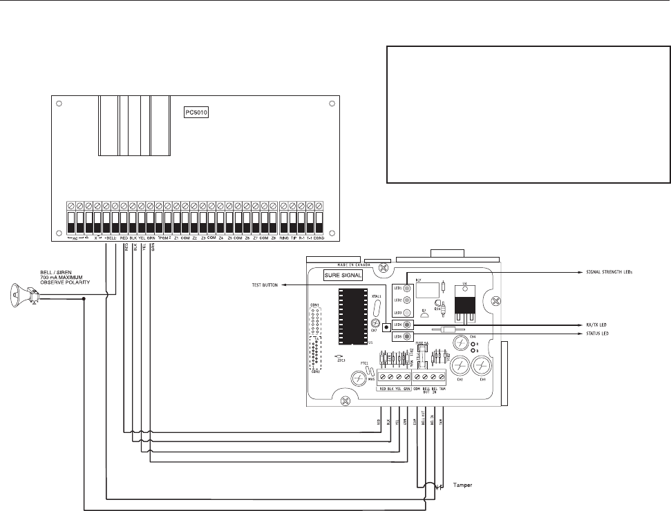
Wiring Connections
Keybus Connection
The Sure Signal transmitter has 4 terminals marked red, black,
yellow and green. Connect these four terminals to the 4 terminals
on the main control panel marked Keybus (red, black, yellow and
green).
Bell IN Terminal
This terminal is used to power the radio modem. This connects
to the BELL + on the control panel. No other wire should be
connected to the BELL+ of the control panel.
An extra power supply can be used to power the modem if it is
not located near the main control panel or where the system
cannot provide enough power for the transmissions. Connect
the positive of the power supply to the BELL IN and the negative
to the COM to ensure proper grounding.
Bell OUT Terminal
This terminal is used to power the siren or any other devices that
would usually connect to the control panel BELL+ terminal. This
output is powered through the 5A fuse (F1) for protection of the
radio transmitting power.
Tamper Terminal
Connect TAM and COM to a normally closed switch that will
be used to monitor tamper. If no tamper switch is desired
place a wire between TAM and COM.
Secure Installation
For a secure installation, the Sure Signal module and its host
panel must be locked and protected. An instant trip IR sensor
would be the most appropriate for supervision of the panel. A
cabinet tamper switch connected to the TAM terminal of the
UL Requirements
Installation-The product is intended to be installed in
accordance with its installation instructions, the local
authority having jurisdiction.
For Grade AA and A Central Station Service:
•The polling between the premise radio and the central
station shall be such that a failure of the radio link shall
be annunciated in 200 seconds at the central station.
Programming006: Option 2 must be on and Option 3 must
be off.
•The radio shall be mounted in an attack resistant enclosure.
•Simultaneous alarm signals shall be sent over the DACT
line and radio.
•Failure of the premise radio shall be reported over the
DACT line and annunciated at the central station within
200 seconds.
•Failure of the DACT line shall be reported over the radio
and annunciated at the central station within 200 seconds.
•Opening and closing signals must be transmitted over the
radio or the DACT line.
For Grade B central station service and grade A police station
connect with high line security:
•The radio shall be mounted in an attack resistant enclosure.
•The system shall send a check-in signal to the central
station every 24 hours.
•A listed compatible burglar alarm sounding device shall
be used in conjunction with the system.
•Opening and closing signals are not required for Police
station connect service.
For grade C central station service:
•The radio shall be mounted in an attack resistant enclosure.
•The system shall send a check-in signal to the central
station every 24 hours.
3
Connection Diagram
AU
WARNING!
All connections to the Sure Signal module are power
limited. Do not route any wiring over the circuit boards.
Maintain at least 1” (25.4mm) seperation between circuit
board and wiring.
A minimum of 1/4” (7mm) separation must be maintained
at all points between non power limited wiring and power
limited wiring.
Refer to your control panel installation manual for any
additional information.

4
Enrolling the Sure Signal Radio
Before powering up the radio, information must be provided to
Connect24 for the Sure Signal Radio. The radio information must
be given to Connect24on the service request form. Once the
service has been set up by the provider, the installer will have to
select the appropriate provider (from the predefined list in this
manual) in the network connection selections section. The
installer must ensure that the Mailbox section is disabled. Both
the receiver radio and Sure Signal must be set up with the
same provider in order to function.
When changing network providers, the subscription to the
previous network should be cancelled. Otherwise, Sure Signal
will remain connected to the previous network if it cannot find
the new network.
Once the previous subscription is cancelled, the installer needs only
to follow the enrollment procedure as described above.
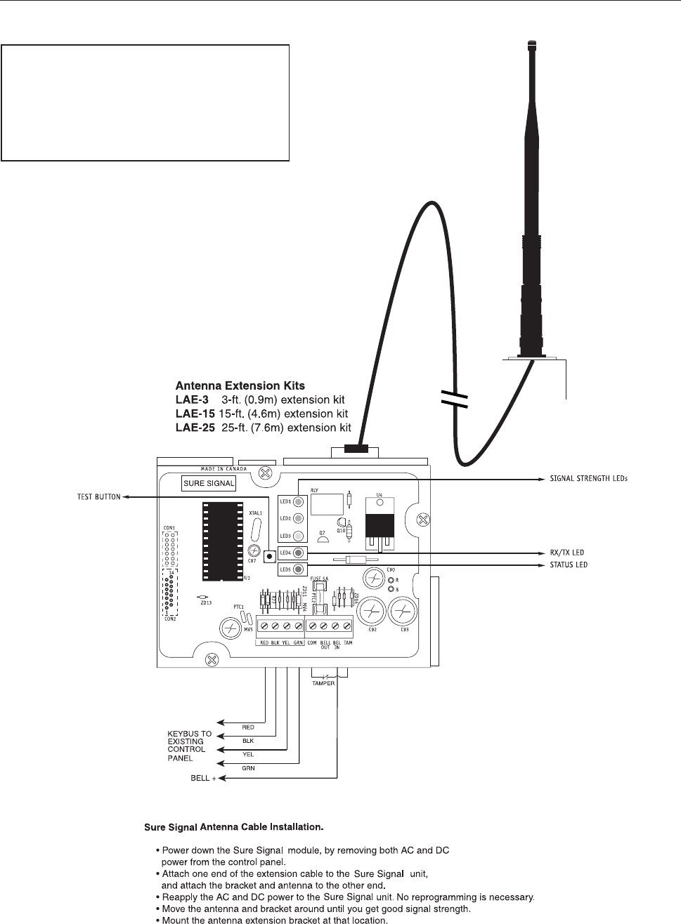
Relocating the Antenna
If a suitable location is not available for proper Mobitex
coverage, obtain an Antenna Extension Bracket kit from your SG
Wireless Communications supplier. Each kit contains an exten-
sion cable, a mounting bracket, instructions, and all required
hardware. Three lengths of extension cable are available:
Extension Kit Length of cable
LAE-3 3 feet (0.91 m)
LAE-15 15 feet (4.57 m)
LAE-25 25 feet (7.62 m)
Only use the Extension Kits to extend the mounting range of
the antenna. Do not cut or splice the extension cable. The
maximum distance between Sure Signal and the antenna is 25
feet (7.62 m) as obtained by using the LAE-25 Extension Kit.
Make sure the antenna is in a physically secured location to
avoid tampering.Secure the TNC connector from the Exten-
sion Kit to the mounting bracket, ensuring that the star
washers make solid electrical contact with the mounting
bracket.Remove the antenna from the Sure Signal module
and connect the extension cable to the TNC connector on the
module. Secure the antenna to the TNC connector mounted
on the Extension Kit Mounting Bracket. Locate the mounting
bracket and antenna away from possible sources of electrical
interference. Moving the antenna just a short distance will
likely be adequate. Temporarily secure the mounting bracket
in the new location and proceed with testing. If the test is
successful, permanently secure the mounting bracket and
antenna at the new location.
Note: 30cm must be kept between antenna and a person/
Relocating the Sure Signal
Since Sure Signal is a Keybus accessory, it is possible to
relocate the module up to 1000 feet from the main control
panel when the panel is not located in a good Mobitex
coverage area (a control panel installed in a vault for
example). When relocating the module, follow theses rules:
•Maximum of 1000 feet from the main control. Keybus
(Red, Black, Yellow, Green) from the panel to the
Sure Signal.
•A UL1481 power supply 12V@1.5A must be used.
•The power supply (AUX+) is connected to the
Sure Signal (BELL IN) terminal and the power supply
(BLK) to the Sure Signal (COM) terminal.
•The cabinet must be installed in a secure location and
should have a tamper circuit connected to the
Sure Signal (TAM and COM) terminals.
Programming Sections
All programming on Sure Signal is done in the installer’s
programming mode. Refer to the control panel’s Installation
Manual for instructions on how to enter installer’s program-
ming. From installer’s programming, enter section [803] to
go to Sure Signal programming sections.
NOTE: Section [06], Option 1 (Radio Enable/Disable) must
be ON before supervision of the module can occur.
[01]-[05] Zone Definition
These sections must be programmed exactly the same as the
main control panel. This allows Sure Signal to translate
information sent along the Keybus and identify the proper event.
[06] Configuration Options
Option [1] Radio Enable/Disable
Option [2] ULAA Supervision Enable/Disable. This option
must be selected to disable ULAA supervision.
Option [3] Standard SIA Test TX / RSSI and Status in Test TX
[10] First Account Number
4-digit hex entry.
[11] Second Account Number
4-digit hex entry.
[15] First Receiver Man Number
Four 2-digit decimal entry.
[16] Second Receiver Man Number
Four 2-digit decimal entry.
Note: For 7-digit man numbers, the first digit must be 0.
[20] Communicator Format Options
2-digit entry.
01 = Condensed SIA without account number
02 = Condensed SIA with account numbers
[21] Network Connection Selections
2-digit entry.
00 = No network selected
01 = Connect to Cantel network
02 = Connect to Ram/Ardus network
03 = Connect to Ram/Aust network
[22] Transmission Options
This section will enable sections of reporting codes.
[23] Number of Attempts to Each Man
3-digit entry (001-255).
[24] Response Wait Time
3-digit entry (001-255) × 10 seconds.
[30]-[78] Individual Event - Transmission Toggle
These sections are used to determine if an event will be
transmitted by Sure Signal. If ’00’ is entered, then that event will
not be transmitted. If ‘FF’ is programmed, then the event will be
transmitted. ‘FF’ is the default value.

5
Activating Sure Signal
Before activating Sure Signal, ensure that the control panel is
wired, programmed and operating properly. Make sure that the
Sure Signal transmitter is properly connected to the Keybus and
to the bell positive circuit. When power is applied to the
system, Sure Signal will perform self-diagnostics for a few
seconds, before giving visual feedback by indicating signal
strength on LED1, LED2 and LED3. A complete default of
the Sure Signal module should always be performed
before any other programming is done. Enter ‘00’ in
section ‘99’ to perform the default.
Transmitting and Receiving
LED4 on the Sure Signal module will blink once (1) to
indicate the radio has transmitted an event. It will blink twice
(2) to indicate that an acknowledgement has been received
from the alarm central station. Sure Signal will not follow
Transmission Delay as programmed in Section [370] of the
panel. Events will be transmitted immediately.
Test Transmissions
Sure Signal will send test transmissions as they come across the
Keybus. All of the programming for timed test transmissions is
done at the panel. When the test transmissions come across the
Keybus, they will be transmitted as per SIA reporting codes
(Appendix A).
Sure Signal can also be set up for ULAA Listed systems. When
ULAA supervision is enabled (Section [06], bit 2OFF), Sure Signal
is responsible for test transmission times. A test transmission
must be sent every 30 minutes if the panel is disarmed, and every
3 minutes if the panel is armed (either or both partitions on a
partitioned system).
There is also a Sure Signal test transmission switch (SW1)
located on its printed circuit board. None of the test
transmissions are affected by transmission options (Section
[803], Option [22]). They can only be enabled/disabled in
the Test Transmission Reporting Codes section (Section
[803], Option [78]).
Sure Signal Trouble Supervision
Sure Signal automatically monitors its operation and indicates
trouble conditions by flashing LED5 on the circuit board. LED5
normally flashes once every second when Sure Signal is on
standby (ready to transmit) mode. Troubles are indicated when
LED5 flashes more than once every second. Shown below is the
number of flashes used to indicate each trouble condition in order
of importance:
2, 6, 3, 4, 5, 1
TABLE 1:
Number
of flashes Function of flashes
1Radio is operating normally
2Radio is not connected or not responding
3Network is not available
4FTC (Failure to Communicate) 1 -
MPAK Flag reason
5FTC (Failure to Communicate) 2 -
Radio reason
6No number programmed for Man Number 1
(Section [15])
Sure Signal Trouble Shooting
1. Check all wiring
•Make sure all the Keybus connections are correct.
•Make sure BELL+ is connected to the BELL IN of the
Sure Signal module.
2. Check the LED5
•Check number of flashes on LED5. If LED flashes more
than once every half second refer to TABLE 1.
•6 flashes indicates no number programmed for Man
Number 1 (Section [15]).
3. If intermittent failure to communicate is seen (5
flashes), number of attempts (option 23) should be
increased to 10 and/or response wait time should be
increased to 60 seconds (option 24=006).
4. If LED5 flashes once every half second, yet Sure Signal
does not communicate, call SG Wireless Technical Support
at 1-888-623-7873 ext.1 or 416-665-0051 ext.1.
5. Before contacting Technical Support, please have the
following information ready: MAN number of the
Sure Signal unit, ESN number of the Sure Signal unit and
account number.

6
[803] Sure Signal Programming (PC5010/580/1555/5015)
Zone Definitions
00 Null Zone (No Alarm) 09 24 Hour Supervisory 18 24 Hour Sprinkler
01 Delay 1 10 24 Hour Supervisory Buzzer 19 24 Hour Water
02 Delay 2 11 24 Hour Burglary 20 24 Hour Freeze
03 Instant 12 24 Hour Holdup 21 24 Hour Latching Tamper
04 Interior 13 24 Hour Gas 22 Momentary Keyswitch Arm
05 Interior, Stay-Away 14 24 Hour Heat 23 Maintained Keyswitch Arm
06 Delay, Stay-Away 15 24 Hour Medical 24 LINKS Answer
07 Delayed 24 Hour Fire (Hardwired) 16 24 Hour Panic 87 Delayed 24 Hour Fire (Wireless)
08 Standard 24 Hour Fire (Hardwired) 17 24 Hour Emergency 88 Standard 24 Hour Fire (Wireless)
[01] Zone 1-8 Definitions
Default Default
00 I_____I_____I Zone 1 00 I_____I_____I Zone 5
00 I_____I_____I Zone 2 00 I_____I_____I Zone 6
00 I_____I_____I Zone 3 00 I_____I_____I Zone 7
00 I_____I_____I Zone 4 00 I_____I_____I Zone 8
[02] Zone 9-16 Definitions
00 I_____I_____I Zone 9 00 I_____I_____I Zone 13
00 I_____I_____I Zone 10 00 I_____I_____I Zone 14
00 I_____I_____I Zone 11 00 I_____I_____I Zone 15
00 I_____I_____I Zone 12 00 I_____I_____I Zone 16
[03] Zone 17-24 Definitions
00 I_____I_____I Zone 17 00 I_____I_____I Zone 21
00 I_____I_____I Zone 18 00 I_____I_____I Zone 22
00 I_____I_____I Zone 19 00 I_____I_____I Zone 23
00 I_____I_____I Zone 20 00 I_____I_____I Zone 24
[04] Zone 25-32 Definitions
00 I_____I_____I Zone 25 00 I_____I_____I Zone 29
00 I_____I_____I Zone 26 00 I_____I_____I Zone 30
00 I_____I_____I Zone 27 00 I_____I_____I Zone 31
00 I_____I_____I Zone 28 00 I_____I_____I Zone 32
[05] PGM2 Definition
00 I_____I_____I If PGM2 is used as 2 Wire Smoke, Silent 24 Hour or Audible 24 Hour.
[06] Sure Signal Configuration Options
Default Option ON Option OFF
OFF I_____I Option 1 Radio is Enabled Disabled
ON I_____I Option 2 ULAA Supervision is Disabled Enabled
OFF I_____I Option 3 Standard SIA RSS1 and status with TX
I_____I Option 4 to 8 For Future Use
[10] Sure Signal First Account Number
FF FF I_____I_____I - I_____I_____I (00 00 - FF FF)
[11] Sure Signal Second Account Number
FF FF I_____I_____I - I_____I_____I (00 00 - FF FF)
[15] First Receiver Man Number
FF FF FF FF I_____I_____I - I_____I_____I - I_____I_____I - I_____I_____I
Valid entries for all 2-digit sections (00-99) decimal. NOTE: For most applications, first digit is ‘0’.

7
[16] Second Receiver Man Number (four 2-digit entries)
Default
FF FF FF FF I_____I_____I - I_____I_____I - I_____I_____I - I_____I_____I
Valid entries for all 2-digit sections (00-99) decimal. NOTE: For most applications, first digit is ‘0’.
[20] Communicator Format Options
Default
02 I_____I_____I
01 = Condensed SIA without transmitted account number
02 = Condensed SIA with 4-digit account number
[21] Network Connection Selections
I_____I_____I
00 = No network selected
01 = Connect to Cantel network
02 = Connect to Ram/Ardus network
03 = Connect to Ram/Aust network
[22] Transmission Options
Default Option ON Option OFF
ON I_____I Option 1 Alarms/Restorals Disabled
ON I_____I Option 2 Tampers/Restorals Disabled
ON I_____I Option 3 Zone Supervisory Alarms/Restorals Disabled
ON I_____I Option 4 Low Battery Alarms/Restorals Disabled
OFF I_____I Option 5 Openings/Closings Disabled
ON I_____I Option 6 Maintenance Alarms/Restorals Disabled
OFF I_____I Option 7 For future use Disabled
OFF I_____I Option 8 For future use Disabled
[23] Number of Attempts
003 I_____I_____I_____I 001 – 255 (decimal)
[24] Response Wait Time
005 I_____I_____I_____I 001 – 255 (decimal, ×10 seconds)
Note: Programming 000 in this section will be accepted as 001. (It will remain as 000 in the programming section.)

8
These are “ON” or “OFF” toggle options
Sections [30] to [78]: if ’00’ is entered, then that reporting code is disabled (“OFF”). If ‘FF’ is in the section,
then the default reporting code is enabled (“ON”).
[30] Alarm Reporting Codes, Zones 1-8
Default Default
FF I_____I_____I Zone 1 Alarm FF I_____I_____I Zone 5 Alarm
FF I_____I_____I Zone 2 Alarm FF I_____I_____I Zone 6 Alarm
FF I_____I_____I Zone 3 Alarm FF I_____I_____I Zone 7 Alarm
FF I_____I_____I Zone 4 Alarm FF I_____I_____I Zone 8 Alarm
[31] Alarm Reporting Codes, Zones 9-16
FF I_____I_____I Zone 9 Alarm FF I_____I_____I Zone 13 Alarm
FF I_____I_____I Zone 10 Alarm FF I_____I_____I Zone 14 Alarm
FF I_____I_____I Zone 11 Alarm FF I_____I_____I Zone 15 Alarm
FF I_____I_____I Zone 12 Alarm FF I_____I_____I Zone 16 Alarm
[32] Alarm Reporting Codes, Zones 17-24
FF I_____I_____I Zone 17 Alarm FF I_____I_____I Zone 21 Alarm
FF I_____I_____I Zone 18 Alarm FF I_____I_____I Zone 22 Alarm
FF I_____I_____I Zone 19 Alarm FF I_____I_____I Zone 23 Alarm
FF I_____I_____I Zone 20 Alarm FF I_____I_____I Zone 24 Alarm
[33] Alarm Reporting Codes, Zones 25-32
FF I_____I_____I Zone 25 Alarm FF I_____I_____I Zone 29 Alarm
FF I_____I_____I Zone 26 Alarm FF I_____I_____I Zone 30 Alarm
FF I_____I_____I Zone 27 Alarm FF I_____I_____I Zone 31 Alarm
FF I_____I_____I Zone 28 Alarm FF I_____I_____I Zone 32 Alarm
[34] Alarm Restoral Reporting Codes, Zones 1-8
Default Default
FF I_____I_____I Zone 1 Alarm Restoral FF I_____I_____I Zone 5 Alarm Restoral
FF I_____I_____I Zone 2 Alarm Restoral FF I_____I_____I Zone 6 Alarm Restoral
FF I_____I_____I Zone 3 Alarm Restoral FF I_____I_____I Zone 7 Alarm Restoral
FF I_____I_____I Zone 4 Alarm Restoral FF I_____I_____I Zone 8 Alarm Restoral
[35] Alarm Restoral Reporting Codes, Zones 9-16
FF I_____I_____I Zone 9 Alarm Restoral FF I_____I_____I Zone 13 Alarm Restoral
FF I_____I_____I Zone 10 Alarm Restoral FF I_____I_____I Zone 14 Alarm Restoral
FF I_____I_____I Zone 11 Alarm Restoral FF I_____I_____I Zone 15 Alarm Restoral
FF I_____I_____I Zone 12 Alarm Restoral FF I_____I_____I Zone 16 Alarm Restoral
[36] Alarm Restoral Reporting Codes, Zones 17-24
FF I_____I_____I Zone 17 Alarm Restoral FF I_____I_____I Zone 21 Alarm Restoral
FF I_____I_____I Zone 18 Alarm Restoral FF I_____I_____I Zone 22 Alarm Restoral
FF I_____I_____I Zone 19 Alarm Restoral FF I_____I_____I Zone 23 Alarm Restoral
FF I_____I_____I Zone 20 Alarm Restoral FF I_____I_____I Zone 24 Alarm Restoral
[37] Alarm Restoral Reporting Codes, Zones 25-32
FF I_____I_____I Zone 25 Alarm Restoral FF I_____I_____I Zone 29 Alarm Restoral
FF I_____I_____I Zone 26 Alarm Restoral FF I_____I_____I Zone 30 Alarm Restoral
FF I_____I_____I Zone 27 Alarm Restoral FF I_____I_____I Zone 31 Alarm Restoral
FF I_____I_____I Zone 28 Alarm Restoral FF I_____I_____I Zone 32 Alarm Restoral

9
[38] Miscellaneous Alarm Reporting Codes
FF I_____I_____I Duress Alarm FF I_____I_____I Zone Expander Supervisory Alarm
FF I_____I_____I Opening After Alarm FF I_____I_____I Zone Expander Supervisory Restoral
FF I_____I_____I Recent Closing FF I_____I_____I Cross Zoning (Burglary Verified) Alarm
[39] Priority Alarm and Restoral Reporting Codes
FF I_____I_____I Keypad [F]ire Alarm FF I_____I_____I Keypad [F]ire Restoral
FF I_____I_____I Keypad [A]uxiliary Alarm FF I_____I_____I Keypad [A]uxiliary Restoral
FF I_____I_____I Keypad [P]anic Alarm FF I_____I_____I Keypad [P]anic Restoral
FF I_____I_____I PGM2 Alarm FF I_____I_____I PGM2 Restoral
[40] Tamper Reporting Codes, Zones 1-8
FF I_____I_____I Zone 1 Tamper FF I_____I_____I Zone 5 Tamper
FF I_____I_____I Zone 2 Tamper FF I_____I_____I Zone 6 Tamper
FF I_____I_____I Zone 3 Tamper FF I_____I_____I Zone 7 Tamper
FF I_____I_____I Zone 4 Tamper FF I_____I_____I Zone 8 Tamper
[41] Tamper Reporting Codes, Zones 9-16
FF I_____I_____I Zone 9 Tamper FF I_____I_____I Zone 13 Tamper
FF I_____I_____I Zone 10 Tamper FF I_____I_____I Zone 14 Tamper
FF I_____I_____I Zone 11 Tamper FF I_____I_____I Zone 15 Tamper
FF I_____I_____I Zone 12 Tamper FF I_____I_____I Zone 16 Tamper
[42] Tamper Reporting Codes, Zones 17-24
FF I_____I_____I Zone 17 Tamper FF I_____I_____I Zone 21 Tamper
FF I_____I_____I Zone 18 Tamper FF I_____I_____I Zone 22 Tamper
FF I_____I_____I Zone 19 Tamper FF I_____I_____I Zone 23 Tamper
FF I_____I_____I Zone 20 Tamper FF I_____I_____I Zone 24 Tamper
[43] Tamper Reporting Codes, Zones 25-32
Default Default
FF I_____I_____I Zone 25 Tamper FF I_____I_____I Zone 29 Tamper
FF I_____I_____I Zone 26 Tamper FF I_____I_____I Zone 30 Tamper
FF I_____I_____I Zone 27 Tamper FF I_____I_____I Zone 31 Tamper
FF I_____I_____I Zone 28 Tamper FF I_____I_____I Zone 32 Tamper
[44] Tamper Restoral Reporting Codes, Zones 1-8
FF I_____I_____I Zone 1 Tamper Restoral FF I_____I_____I Zone 5 Tamper Restoral
FF I_____I_____I Zone 2 Tamper Restoral FF I_____I_____I Zone 6 Tamper Restoral
FF I_____I_____I Zone 3 Tamper Restoral FF I_____I_____I Zone 7 Tamper Restoral
FF I_____I_____I Zone 4 Tamper Restoral FF I_____I_____I Zone 8 Tamper Restoral
[45] Tamper Restoral Reporting Codes, Zones 9-16
FF I_____I_____I Zone 9 Tamper Restoral FF I_____I_____I Zone 13 Tamper Restoral
FF I_____I_____I Zone 10 Tamper Restoral FF I_____I_____I Zone 14 Tamper Restoral
FF I_____I_____I Zone 11 Tamper Restoral FF I_____I_____I Zone 15 Tamper Restoral
FF I_____I_____I Zone 12 Tamper Restoral FF I_____I_____I Zone 16 Tamper Restoral
[46] Tamper Restoral Reporting Codes, Zones 17-24
FF I_____I_____I Zone 17 Tamper Restoral FF I_____I_____I Zone 21 Tamper Restoral
FF I_____I_____I Zone 18 Tamper Restoral FF I_____I_____I Zone 22 Tamper Restoral
FF I_____I_____I Zone 19 Tamper Restoral FF I_____I_____I Zone 23 Tamper Restoral
FF I_____I_____I Zone 20 Tamper Restoral FF I_____I_____I Zone 24 Tamper Restoral

10
[47] Tamper Restoral Reporting Codes, Zones 25-32
FF I_____I_____I Zone 25 Tamper Restoral FF I_____I_____I Zone 29 Tamper Restoral
FF I_____I_____I Zone 26 Tamper Restoral FF I_____I_____I Zone 30 Tamper Restoral
FF I_____I_____I Zone 27 Tamper Restoral FF I_____I_____I Zone 31 Tamper Restoral
FF I_____I_____I Zone 28 Tamper Restoral FF I_____I_____I Zone 32 Tamper Restoral
[48] Miscellaneous Tamper Reporting Codes
FF I_____I_____I General System Tamper FF I_____I_____I Keypad Lockout
FF I_____I_____I General System Tamper Rest.
[49] Supervisory Reporting Codes, Zones 1-8
FF I_____I_____I Zone 1 Supervisory FF I_____I_____I Zone 5 Supervisory
FF I_____I_____I Zone 2 Supervisory FF I_____I_____I Zone 6 Supervisory
FF I_____I_____I Zone 3 Supervisory FF I_____I_____I Zone 7 Supervisory
FF I_____I_____I Zone 4 Supervisory FF I_____I_____I Zone 8 Supervisory
[50] Supervisory Reporting Codes, Zones 9-16
FF I_____I_____I Zone 9 Supervisory FF I_____I_____I Zone 13 Supervisory
FF I_____I_____I Zone 10 Supervisory FF I_____I_____I Zone 14 Supervisory
FF I_____I_____I Zone 11 Supervisory FF I_____I_____I Zone 15 Supervisory
FF I_____I_____I Zone 12 Supervisory FF I_____I_____I Zone 16 Supervisory
[51] Supervisory Reporting Codes, Zones 17-24
FF I_____I_____I Zone 17 Supervisory FF I_____I_____I Zone 21 Supervisory
FF I_____I_____I Zone 18 Supervisory FF I_____I_____I Zone 22 Supervisory
FF I_____I_____I Zone 19 Supervisory FF I_____I_____I Zone 23 Supervisory
FF I_____I_____I Zone 20 Supervisory FF I_____I_____I Zone 24 Supervisory
[52] Supervisory Reporting Codes, Zones 25-32
Default Default
FF I_____I_____I Zone 25 Supervisory FF I_____I_____I Zone 29 Supervisory
FF I_____I_____I Zone 26 Supervisory FF I_____I_____I Zone 30 Supervisory
FF I_____I_____I Zone 27 Supervisory FF I_____I_____I Zone 31 Supervisory
FF I_____I_____I Zone 28 Supervisory FF I_____I_____I Zone 32 Supervisory
[53] Supervisory Restoral Reporting Codes, Zones 1-8
FF I_____I_____I Zone 1 Supervisory Restoral FF I_____I_____I Zone 5 Supervisory Restoral
FF I_____I_____I Zone 2 Supervisory Restoral FF I_____I_____I Zone 6 Supervisory Restoral
FF I_____I_____I Zone 3 Supervisory Restoral FF I_____I_____I Zone 7 Supervisory Restoral
FF I_____I_____I Zone 4 Supervisory Restoral FF I_____I_____I Zone 8 Supervisory Restoral
[54] Supervisory Restoral Reporting Codes, Zones 9-16
FF I_____I_____I Zone 9 Supervisory Restoral FF I_____I_____I Zone 13 Supervisory Restoral
FF I_____I_____I Zone 10 Supervisory Restoral FF I_____I_____I Zone 14 Supervisory Restoral
FF I_____I_____I Zone 11 Supervisory Restoral FF I_____I_____I Zone 15 Supervisory Restoral
FF I_____I_____I Zone 12 Supervisory Restoral FF I_____I_____I Zone 16 Supervisory Restoral
[55] Supervisory Restoral Reporting Codes, Zones 17-24
FF I_____I_____I Zone 17 Supervisory Restoral FF I_____I_____I Zone 21 Supervisory Restoral
FF I_____I_____I Zone 18 Supervisory Restoral FF I_____I_____I Zone 22 Supervisory Restoral
FF I_____I_____I Zone 19 Supervisory Restoral FF I_____I_____I Zone 23 Supervisory Restoral
FF I_____I_____I Zone 20 Supervisory Restoral FF I_____I_____I Zone 24 Supervisory Restoral

11
[56] Supervisory Restoral Reporting Codes, Zones 25-32
FF I_____I_____I Zone 25 Supervisory Restoral FF I_____I_____I Zone 29 Supervisory Restoral
FF I_____I_____I Zone 26 Supervisory Restoral FF I_____I_____I Zone 30 Supervisory Restoral
FF I_____I_____I Zone 27 Supervisory Restoral FF I_____I_____I Zone 31 Supervisory Restoral
FF I_____I_____I Zone 28 Supervisory Restoral FF I_____I_____I Zone 32 Supervisory Restoral
[57] Low Battery Reporting Codes, Zones 1-8
FF I_____I_____I Zone 1 Low Battery FF I_____I_____I Zone 5 Low Battery
FF I_____I_____I Zone 2 Low Battery FF I_____I_____I Zone 6 Low Battery
FF I_____I_____I Zone 3 Low Battery FF I_____I_____I Zone 7 Low Battery
FF I_____I_____I Zone 4 Low Battery FF I_____I_____I Zone 8 Low Battery
[58] Low Battery Reporting Codes, Zones 9-16
FF I_____I_____I Zone 9 Low Battery FF I_____I_____I Zone 13 Low Battery
FF I_____I_____I Zone 10 Low Battery FF I_____I_____I Zone 14 Low Battery
FF I_____I_____I Zone 11 Low Battery FF I_____I_____I Zone 15 Low Battery
FF I_____I_____I Zone 12 Low Battery FF I_____I_____I Zone 16 Low Battery
[59] Low Battery Reporting Codes, Zones 17-24
FF I_____I_____I Zone 17 Low Battery FF I_____I_____I Zone 21 Low Battery
FF I_____I_____I Zone 18 Low Battery FF I_____I_____I Zone 22 Low Battery
FF I_____I_____I Zone 19 Low Battery FF I_____I_____I Zone 23 Low Battery
FF I_____I_____I Zone 20 Low Battery FF I_____I_____I Zone 24 Low Battery
[60] Low Battery Reporting Codes, Zones 25-32
FF I_____I_____I Zone 25 Low Battery FF I_____I_____I Zone 29 Low Battery
FF I_____I_____I Zone 26 Low Battery FF I_____I_____I Zone 30 Low Battery
FF I_____I_____I Zone 27 Low Battery FF I_____I_____I Zone 31 Low Battery
FF I_____I_____I Zone 28 Low Battery FF I_____I_____I Zone 32 Low Battery
[61] Low Battery Restoral Reporting Codes, Zones 1-8
Default Default
FF I_____I_____I Zone 1 Low Battery Restoral FF I_____I_____I Zone 5 Low Battery Restoral
FF I_____I_____I Zone 2 Low Battery Restoral FF I_____I_____I Zone 6 Low Battery Restoral
FF I_____I_____I Zone 3 Low Battery Restoral FF I_____I_____I Zone 7 Low Battery Restoral
FF I_____I_____I Zone 4 Low Battery Restoral FF I_____I_____I Zone 8 Low Battery Restoral
[62] Low Battery Restoral Reporting Codes, Zones 9-16
FF I_____I_____I Zone 9 Low Battery Restoral FF I_____I_____I Zone 13 Low Battery Restoral
FF I_____I_____I Zone 10 Low Battery Restoral FF I_____I_____I Zone 14 Low Battery Restoral
FF I_____I_____I Zone 11 Low Battery Restoral FF I_____I_____I Zone 15 Low Battery Restoral
FF I_____I_____I Zone 12 Low Battery Restoral FF I_____I_____I Zone 16 Low Battery Restoral
[63] Low Battery Restoral Reporting Codes, Zones 17-24
FF I_____I_____I Zone 17 Low Battery Restoral FF I_____I_____I Zone 21 Low Battery Restoral
FF I_____I_____I Zone 18 Low Battery Restoral FF I_____I_____I Zone 22 Low Battery Restoral
FF I_____I_____I Zone 19 Low Battery Restoral FF I_____I_____I Zone 23 Low Battery Restoral
FF I_____I_____I Zone 20 Low Battery Restoral FF I_____I_____I Zone 24 Low Battery Restoral
[64] Low Battery Restoral Reporting Codes, Zones 25-32
FF I_____I_____I Zone 25 Low Battery Restoral FF I_____I_____I Zone 29 Low Battery Restoral
FF I_____I_____I Zone 26 Low Battery Restoral FF I_____I_____I Zone 30 Low Battery Restoral
FF I_____I_____I Zone 27 Low Battery Restoral FF I_____I_____I Zone 31 Low Battery Restoral
FF I_____I_____I Zone 28 Low Battery Restoral FF I_____I_____I Zone 32 Low Battery Restoral

12
[65] Closing (Arming) Reporting Codes, Access Codes 1-8
FF I_____I_____I Closing By Access Code 1 FF I_____I_____I Closing By Access Code 5
FF I_____I_____I Closing By Access Code 2 FF I_____I_____I Closing By Access Code 6
FF I_____I_____I Closing By Access Code 3 FF I_____I_____I Closing By Access Code 7
FF I_____I_____I Closing By Access Code 4 FF I_____I_____I Closing By Access Code 8
[66] Closing (Arming) Reporting Codes, Access Codes 9-16
FF I_____I_____I Closing By Access Code 9 FF I_____I_____I Closing By Access Code 13
FF I_____I_____I Closing By Access Code 10 FF I_____I_____I Closing By Access Code 14
FF I_____I_____I Closing By Access Code 11 FF I_____I_____I Closing By Access Code 15
FF I_____I_____I Closing By Access Code 12 FF I_____I_____I Closing By Access Code 16
[67] Closing (Arming) Reporting Codes, Access Codes 17-24
FF I_____I_____I Closing By Access Code 17 FF I_____I_____I Closing By Access Code 21
FF I_____I_____I Closing By Access Code 18 FF I_____I_____I Closing By Access Code 22
FF I_____I_____I Closing By Access Code 19 FF I_____I_____I Closing By Access Code 23
FF I_____I_____I Closing By Access Code 20 FF I_____I_____I Closing By Access Code 24
[68] Closing (Arming) Reporting Codes, Access Codes 25-32
FF I_____I_____I Closing By Access Code 25 FF I_____I_____I Closing By Access Code 29
FF I_____I_____I Closing By Access Code 26 FF I_____I_____I Closing By Access Code 30
FF I_____I_____I Closing By Access Code 27 FF I_____I_____I Closing By Access Code 31
FF I_____I_____I Closing By Access Code 28 FF I_____I_____I Closing By Access Code 32
[69] Miscellaneous Closing (Arming) Reporting Codes
FF I_____I_____I Closing by Duress Code 33 FF I_____I_____I Closing by System Code 42
FF I_____I_____I Closing by Duress Code 34 FF I_____I_____I Partial Closing
FF I_____I_____I Closing by System Code 40 FF I_____I_____I Special Closing
FF I_____I_____I Closing by System Code 41
[70] Opening (Disarming) Reporting Codes, Access Codes 1-8
Default Default
FF I_____I_____I Opening By Access Code 1 FF I_____I_____I Opening By Access Code 5
FF I_____I_____I Opening By Access Code 2 FF I_____I_____I Opening By Access Code 6
FF I_____I_____I Opening By Access Code 3 FF I_____I_____I Opening By Access Code 7
FF I_____I_____I Opening By Access Code 4 FF I_____I_____I Opening By Access Code 8
[71] Opening (Disarming) Reporting Codes, Access Codes 9-16
FF I_____I_____I Opening By Access Code 9 FF I_____I_____I Opening By Access Code 13
FF I_____I_____I Opening By Access Code 10 FF I_____I_____I Opening By Access Code 14
FF I_____I_____I Opening By Access Code 11 FF I_____I_____I Opening By Access Code 15
FF I_____I_____I Opening By Access Code 12 FF I_____I_____I Opening By Access Code 16
[72] Opening (Disarming) Reporting Codes, Access Codes 17-24
FF I_____I_____I Opening By Access Code 17 FF I_____I_____I Opening By Access Code 21
FF I_____I_____I Opening By Access Code 18 FF I_____I_____I Opening By Access Code 22
FF I_____I_____I Opening By Access Code 19 FF I_____I_____I Opening By Access Code 23
FF I_____I_____I Opening By Access Code 20 FF I_____I_____I Opening By Access Code 24
[73] Opening (Disarming) Reporting Codes, Access Codes 25-32
FF I_____I_____I Opening By Access Code 25 FF I_____I_____I Opening By Access Code 29
FF I_____I_____I Opening By Access Code 26 FF I_____I_____I Opening By Access Code 30
FF I_____I_____I Opening By Access Code 27 FF I_____I_____I Opening By Access Code 31
FF I_____I_____I Opening By Access Code 28 FF I_____I_____I Opening By Access Code 32

13
[74] Miscellaneous Opening (Disarming) Reporting Codes
FF I_____I_____I Opening by Duress Code 33 FF I_____I_____I Opening by System Code 42
FF I_____I_____I Opening by Duress Code 34 FF I_____I_____I Auto Arm Cancellation
FF I_____I_____I Opening by System Code 40 FF I_____I_____I Special Opening
FF I_____I_____I Opening by System Code 41
[75] Maintenance Alarm Reporting Codes
FF I_____I_____I Battery Trouble Alarm FF I_____I_____I Auxiliary Power Supply Trouble Alarm
FF I_____I_____I AC Failure Trouble Alarm FF I_____I_____I TLM Trouble Code
FF I_____I_____I Bell Circuit Trouble Alarm FF I_____I_____I General System Trouble
FF I_____I_____I Fire Trouble Alarm FF I_____I_____I General System Supervisory
[76] Maintenance Restoral Reporting Codes
FF I_____I_____I Battery Trouble Restoral FF I_____I_____I Auxiliary Power Supply Trouble Restoral
FF I_____I_____I AC Failure Trouble Restoral FF I_____I_____I TLM Restoral
FF I_____I_____I Bell Circuit Trouble Restoral FF I_____I_____I General System Trouble Restore
FF I_____I_____I Fire Trouble Restoral FF I_____I_____I General System Supervisory Restore
[77] Miscellaneous Maintenance Reporting Codes
FF I_____I_____I Phone #1 FTC FF I_____I_____I Event Buffer 75% Full
FF I_____I_____I Phone #2 FTC FF I_____I_____I DLS Lead IN
FF I_____I_____I Phone #1 FTC Restore FF I_____I_____I DLS Lead OUT
FF I_____I_____I Phone #2 FTC Restore FF I_____I_____I Delinquency Reporting Code
[78] Test Transmission Reporting Codes
FF I_____I_____I Periodic Test Transmission FF I_____I_____I Mobitex Test TX Code
FF I_____I_____I System Test
[99] Section [99] is for software defaulting of Sure Signal
80 I_____I_____I
Entering 00 will cause a software default of Sure Signal. Entering 01-FF will cause restart of Sure Signal. Entering any other
value will not cause a default or a restart.
[993] Inst. Code
Restore Sure Signal to factory default programming.
Note: Sure Signal must be defaulted if it is connected to PC5010 version 1.00.

14
For Your Records
Location ____________________________________________________________
____________________________________________________________
____________________________________________________________
____________________________________________________________
Sure Signal Man Number ____________________________________________________________
Rate Plan ____________________________________________________________
____________________________________________________________
Central Station ____________________________________________________________
Account Number 1 ____________________________________________________________
Account Number 2 ____________________________________________________________
Test Time and Day ____________________________________________________________
Additional Notes ____________________________________________________________
____________________________________________________________
____________________________________________________________
____________________________________________________________

15
Appendix A - SIA Reporting codes
SIA Communication Format
The SIA communication format used in this product follows the Level 2 specifications of the SIA Digital Communication Standard
- February 1993. This format will send the Account Code along with its data transmission. Below are the Zone Alarms & Alarm
Restores (Zones 01-32) as well as any additional codes that can be transmitted:
Terms Code Description
—..........................................Not used
zz ..........................................Zone #
us ..........................................User #
ln ...........................................Line
ex ..........................................Expander #
xx...........................................RSS and status
Alarms Event Description SIA Message Zone# Identified
Null Zone (Not used) - -
Delay 1 BAzz/BHzz Yes
Delay 2 BAzz/BHzz Yes
Instant BAzz/BHzz Yes
Interior BAzz/BHzz Yes
Delay H.A. BAzz/BHzz Yes
Interior H.A. BAzz/BHzz Yes
24 Hr Burglary BAzz/BHzz Yes
Standard Fire FAzz/FHzz Yes
Delayed Fire FAzz/FHzz Yes
24 Hour Supervisory UAzz/UHzz Yes
24 Hr Supervisory Buzzer UAzz/UHzz Yes
24 Hr Supervisory USzz/URzz Yes
24 Hr Medical MAzz/MHzz Yes
24 Hr Panic PAzz/PHzz Yes
24 Hr Hold-up HAzz/HHzz Yes
24 Hr Gas GAzz/GHzz Yes
24 Hr Heat KAzz/KHzz Yes
24 Hr Emergency QAzz/QHzz Yes
24 Hr Sprinkler SAzz/SHzz Yes
24 Hr Water WAzz/WHzz Yes
24 Hr Freeze ZAzz/ZHzz Yes
24 Hr Latching Tamper BAzz/BHzz Yes
Duress Alarm HA00 -
Opening After Alarm OR00 -
Keypad [F]ire FAzz/FHzz Yes
Keypad [A]uxiliary MAzz/MHzz Yes
Keypad [P]anic PAzz/PHzz Yes

16
Event Description SIA Message Zone# Identified
PGM2:
2 Wire Smoke FA99/FH99 -
Audible 24 Hour UA99/UH99 -
Silent 24 Hour UA99/UH99 -
Zone Tamper (1-32) TAzz Yes
Zone Tamper Restorals (1-32) TRzz Yes
General System Tamper / Restore TA00/TR00 -
Closing by Access Codes CLus Yes
(1-32,33,34,40,41,42)
Partial Closing CGus Yes (using UBzz)
Opening by Access Codes OPus Yes
(1-32,33,34,40,41,42)
Battery Trouble YT00/YR00 -
AC Failure Trouble AT00/AR00 -
Bell Circuit Trouble UT99/UJ99 -
Fire Trouble FT00/FJ00 -
Auxiliary Power Supply Trouble YP00/YQ00 -
TLM Trouble Code (via Mobitex) LT00 -
General System Supervisory / Restore ET00/ER00 -
General System Trouble / Restore YX00/YZ00 -
TLM Restoral LR00 -
FTC Fail / FTC Restoral YC00/YK00 -
Event Buffer 75% Full Since Last Upload JL00 -
Periodic Test Transmission RP00 -
Periodic Test Transmission Trouble RP001 -
System Test RX00 -
Mobitex Test Transmission Code TXxx Signal Strength and Status
(ULAA Supersion or Sure Signal test button)
Zone Fault Alarm/Restoral UTzz/UJzz Yes
Burglary Verified BV00 -
Delinquency Code CD00 -
Zone Low Battery XTzz/XRzz Yes
Recent Closing CR00 User NOT Identified
Zone Expander Supervisory UA00/UH00 -
Keypad Lockout JA00 -
Special Closing (DLS, Keys, Maint, Quick) CL00 -
Special Opening (DLS, Keys, Maint) OP00 -
DLS Lead In RB00 -
DLS Lead Out (Successful) RS00 -
Auto-Arm Cancellation CE00 -
Mobitex Tamper Cut TAzz/TRzz Yes
Keybus Fault ET00/ER00 -
Expansion Device ETex/ERex -
17
Antenna Relocation Diagram
WARNING!
All connections to the Sure Signal module are power limited. Do not
route any wiring over the circuit boards. Maintain at least 1” (25.4mm)
seperation between circuit board and wiring.
A minimum of 1/4” (7mm) separation must be maintained at all points
between non power limited wiring and power limited wiring.
Refer to your control panel installation manual for any additional
information.
18
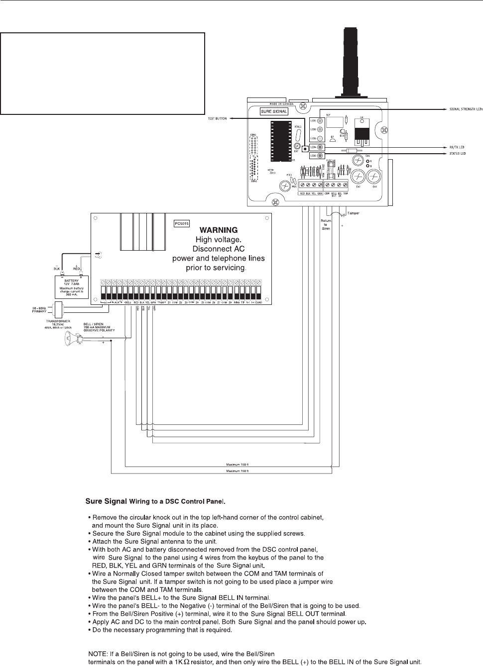
Standard Connection with DSC Control Panel
WARNING!
All connections to the Sure Signal module are power limited. Do not
route any wiring over the circuit boards. Maintain at least 1” (25.4mm)
seperation between circuit board and wiring.
A minimum of 1/4” (7mm) separation must be maintained at all points
between non power limited wiring and power limited wiring.
Refer to your control panel installation manual for any additional
information.

Limited Warranty
SG Wireless Communications warrants that for a period of twelve months from the date of purchase, the product shall be
free from defects in materials and workmanship under normal use and that in fulfillment of any breech of such warranty, SG
Wireless Communications shall, at its option, repair or replace the defective equipment upon return of the equipment to its
repair depot. This warranty applies only to defects in parts and workmanship and not to damage incurred in shipping or
handling, or damage due to causes beyond the control of SG Wireless Communications, such as lightning, excessive voltage,
mechanical shock, water damage, or damage arising out of abuse, alteration or improper application of the equipment.
The foregoing warranty shall apply only to the original buyer, and is and shall be in lieu of any and all other warranties, whether expressed
or implied and of all other obligations or liabilities on the part of SG Wireless Communications. SG Wireless Communications neither
assumes, nor authorizes any other person purporting to act on its behalf to modify or to change this warranty, nor to assume for it
any other warranty or liability concerning this product.
In no event shall SG Wireless Communications be liable for any direct or indirect or consequential damages, loss of anticipated
profits, loss of time or any other losses incurred by the buyer in connection with the purchase, installation or operation or failure
of this product.
WARNING: SG Wireless Communications recommends that the entire system be completely tested on a regular basis.
However, despite frequent testing, and due to but not limited to, criminal tampering or electrical disruption, it is possible for
this product to fail to perform as expected.
How to Contact Us:
Sales
For information about additional products, please call our sales number: 1-888-623-7873, fax us at 1-416-
665-4222 or e-mail us at sales@sur-gard.com.
Technical Support
If you have questions or problems when using Sur-Gard products, you can call technical support. If you are
within the United States, Puerto Rico, the U.S. Virgin Islands or Canada, you can get support by dialing
1-888-623-7873 ext.1. If you are outside these areas, please call (416) 665-5501 ext.1, or e-mail us at
support@sur-gard.com.
Internet
Visit our new Sur-Gard WWW site. You can search the Sur-Gard technical information database and read information
about our new products as well as send us any questions or comments you may have. Our World Wide Web address
is http://www.sur-gard.com.

©2000 SG Wireless Communications
A Division of the SafeLink Corporation
401 Magnetic Drive, Units #24-28
Downsview, Ontario, Canada M3J 3H9
Tel: (416) 665-0051
Fax: (416) 665-4222
Toll Free: 1-888-623-7873
www.sur-gard.com 29005740 R001
Printed in Canada