Diversey R37615-00 Soap Dispenser with 900 MHz ISM User Manual Installation Guides
Diversey Inc Soap Dispenser with 900 MHz ISM Installation Guides
UserManual.wiki
>
Diversey
>
R37615 00 User Manual
Installation Guides
Navigation menu
Upload a User Manual
Namespaces
Wiki Guide
HTML
PDF
Info
Views
User Manual
Discussion / Help
Navigation
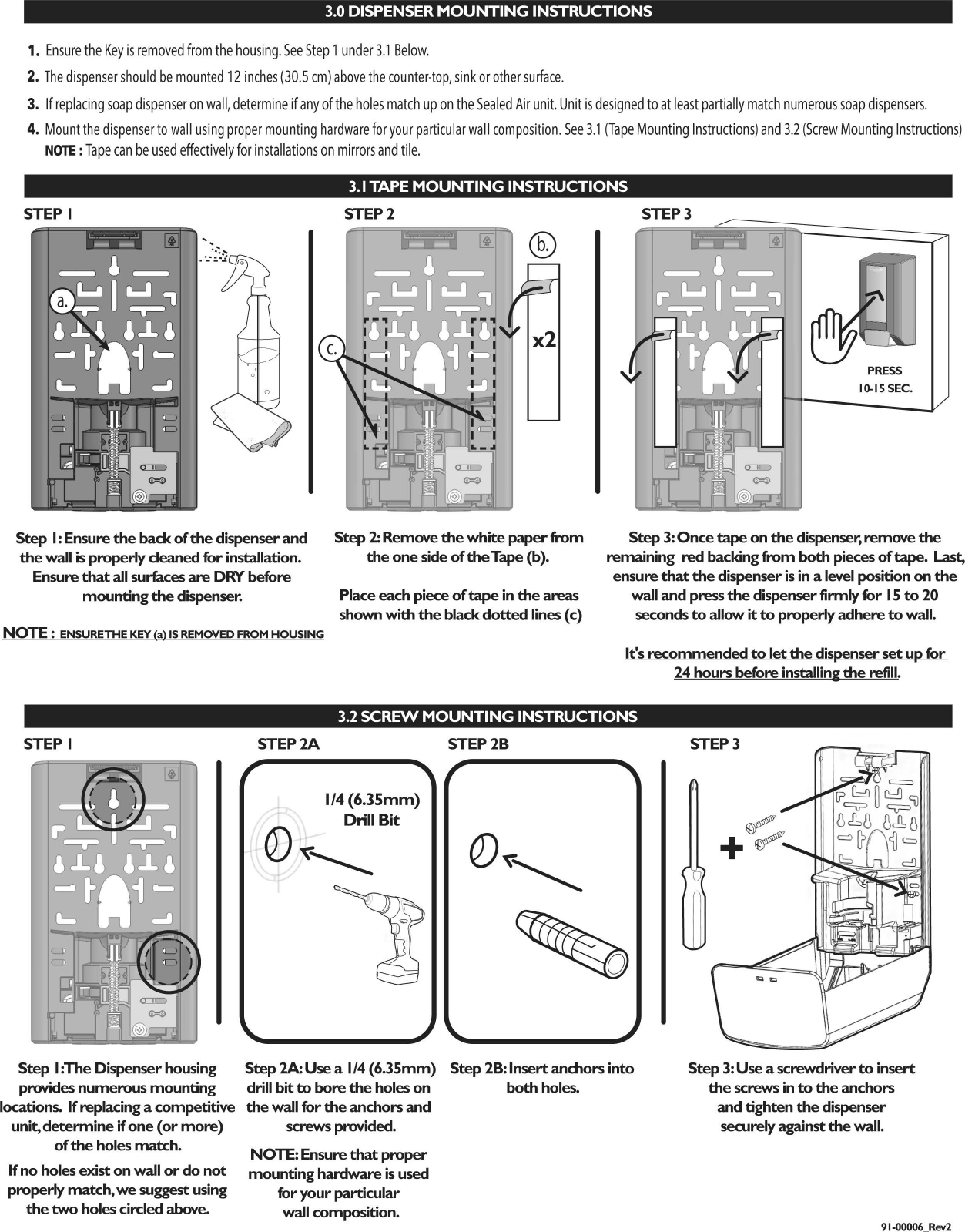
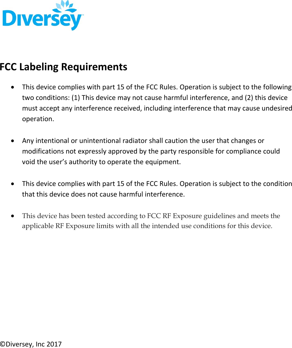
![1.1 DISPENSER INSTALLATION NOTES NOTE: SEE KEY DISPENSER DIMENSIONS BELOW (1.2). IF INSTALLING WITH DRIP CATCH OR ELBOW BAR, SEE CRmCAL DIMENSIONS BELOW (1.5 Drip·Catch and 2.2 Elbow Bar) 1. Remove key from back of housing. (Reference 'Key Location' in section 1.2, below) 2. The dispenser should be mounted 12 inches (30.5 em) above the counter-top, sink or other surface. 3. If replacing soap dispenser on wall, determine if any of the holes match up on the Sealed Air unit. Unit is designed to at least partially match numerous soap dispensers. 4. Mount the dispenser to wall using proper mounting hardware for your particular wall composition. Go to section 3.0 for specific dispenser mounting instructions. NOTE : TAPE & SCREWS/ANCHORS ARE PROVIDED FOR INSTALLATION. DISCLAIMER: If refills (Soap) used other than certified SA soap, SA is not responsible for any dispenser issues. 1.2 DIMENSIONS, KEY LOCATION, OPENING & CLOSING DISPENSER 1.3 REFILL PLACEMENT & REMOVAL **KEY OUTER DIMENSIONS OF DISPENSER : 1Hl10.24" 12fD'v1Ml x 1Wl6" I152.4MMJ x IDI4'' [101.6mml 10.24" {260mm) 6" {152.4mm) KEY LOCATION Remove cover key {a) from back of housing. 1.0 ML DOSE SETIING OPENING COVER Insert key into holes on top of cover then pull cover forward. 'click' • CLOSING COVER To close the cover, simply PUSH the top of cover closed to 'Click' shut {b). TO INSERT REFILL TO REMOVE REFILL Push refill into place to ensure the FLANGE of the Pull the Container {e) and the Pump Soap Nozzle {c) is seated into the correct location {d). Housing (f). Please recycle accordingly. If not, the dispenser will not pump correctly. 1.4 DOSE SIZE CONTROL GUIDE **To change dose setting, open dispenser cover and slide the red Dose Control Switch {a) to your desired dose size, Ensure you slide the Control Switch {a) ALL the way to the left or right. 0.4 ML DOSE SETIING SLIDE DOSE CONTROL SWITCH {a )TO THE LEFTFOR 1.0ML DOSE SETIING. SLIDE DOSE CONTROL SWITCH {a )TO THE RIGHT FOR 0.4ML DOSE SETIING. 1.5 OPTIONAL DRIP-CATCH INSTALLATION Insert drip catch hooks (a) through rectangular slots located at the backside of the dispenser. The Drip-Catch with SNAP into place. NOTE: The Drip Catch is not designed to be removed. However, if going to remove for cleaning please be careful not to damage the dispenser. The drip catch might be damaged after removing. DISCLAIMER: If other drip catch used, Sealed Air not responsible for damage. [ 409.22] 16.111](https://usermanual.wiki/Diversey/R37615-00/User-Guide-3663531-Page-2.png)
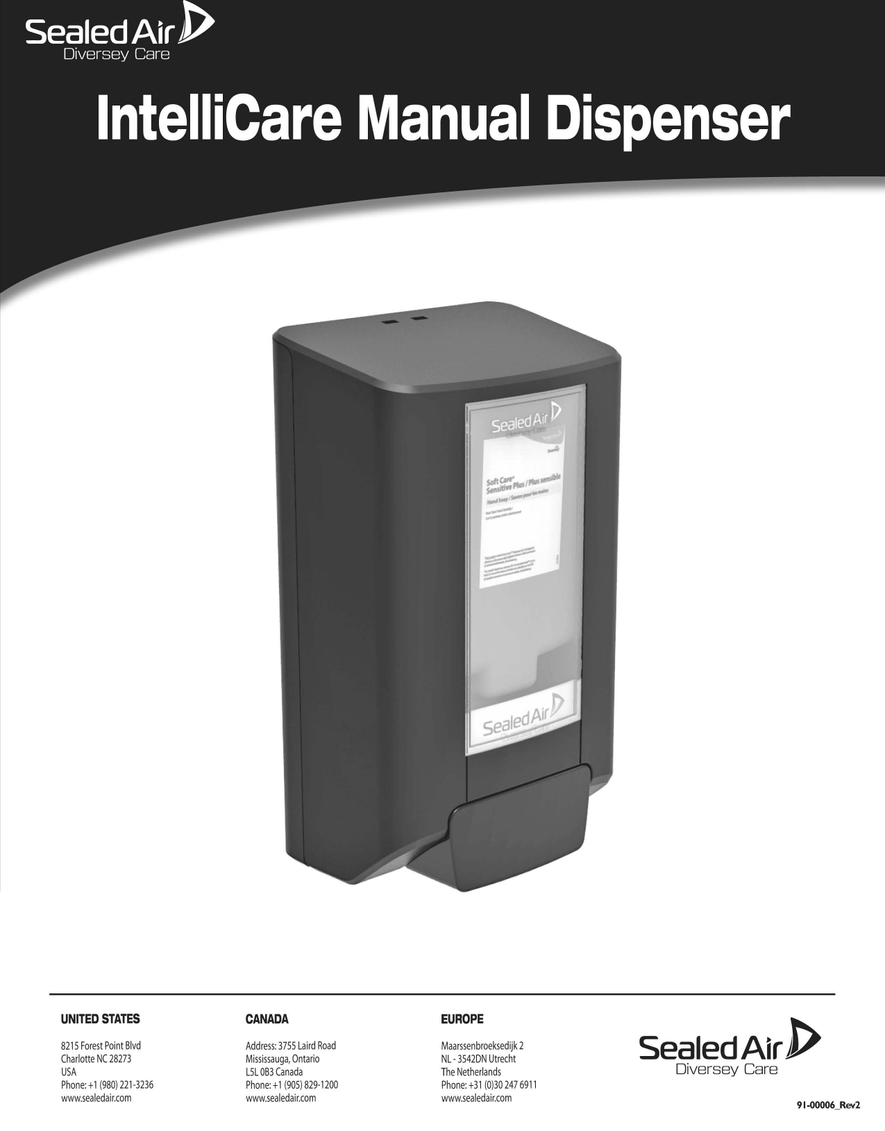
![no.S-2 no.S-1 @ QQ n0.1 Unlock and open Manual Dispenser cover (1 A). n0.2 Remove Refill Bottle (2A) from Dispenser. Use a drill with a 6mm bit to bore a hole in to the 2 pilot holes (3A) no.3 located on the inside left and right sides of the housing unit. 4 Insert the Elbow Bar ends ( 4A) in to each of the holes from the n 0. outside. NOTE: COTTER RINGS (5·1 & 5·2) ARE OPTIONAL. no.4 no.7 no.S-1 Insert Cotter Rings (SA) through Elbow Bar holes (58). no.S-2 Cotter Ring (SA) correctly installed close up view. no.6 no.7 Lift up the elbow bar to a vertical position ( 6A). Re-install the Refill bottle ( 68) before closing the dispenser cover ( 6C). To complete the installation, lower the Elbow Bar (7 A) so that it rests in place on top of the Push Lever. NOTE: To replace refill, you must LIFT up the Elbow Bar (similar to 6A) first, then UNLOCK and LOWER the COVER. MANUAL DISPENSER with ELBOW BAR After replacement of refill, CLOSE cover FIRST(GC) before lowering the Elbow Bar (7A). 2.2 ELBOW BAR- KEY DIMENSIONS 25 10 8.30] .169 FRONT VIEW KEY DIMENSIONS [ 171 10] 6.736 SJJ1J iZC=I\ /t=:!S}' ..1. Jl. ~ r [ 42.11] 1.658 SIDE VIEW KEY DIMENSIONS _[101.6]_ 4.0 r----[ 141.38] __ _)===~=:d...J.~ f--------5._56_6_ [ 242.40 l --------1 9.543](https://usermanual.wiki/Diversey/R37615-00/User-Guide-3663531-Page-3.png)