Diversey R37615-00 Soap Dispenser with 900 MHz ISM User Manual Installation Guides
Diversey Inc Soap Dispenser with 900 MHz ISM Installation Guides
Diversey >
Installation Guides
UNITED
STATES
8215
Forest
Point
Bl
vd
Charlotte
NC
28273
USA
Phone:
t 1 (
980
)
221-3236
www.
sealedair
.
com
CANADA
A
ddress:
3755
Laird
Road
M
ississauga
,
Ontario
L5L
OB3
Canada
Phone:
t 1 (
905
)
829-1200
www.
sealedair
.
com
EUROPE
Maarssenbroeksedijk
2
NL-
3542DN
Utrecht
The
Netherlands
Phone:
t31
(0)
30
247
6911
www
.sealedair.com
Sealed
Air
J>
Diversey
Care
91-00006
_
Rev2
1.1
DISPENSER INSTALLATION
NOTES
NOTE:
SEE
KEY
DISPENSER
DIMENSIONS
BELOW
(1.2).
IF
INSTALLING
WITH
DRIP
CATCH
OR
ELBOW
BAR,
SEE
CRmCAL
DIMENSIONS
BELOW
(1.5
Drip·Catch
and
2.2
Elbow
Bar)
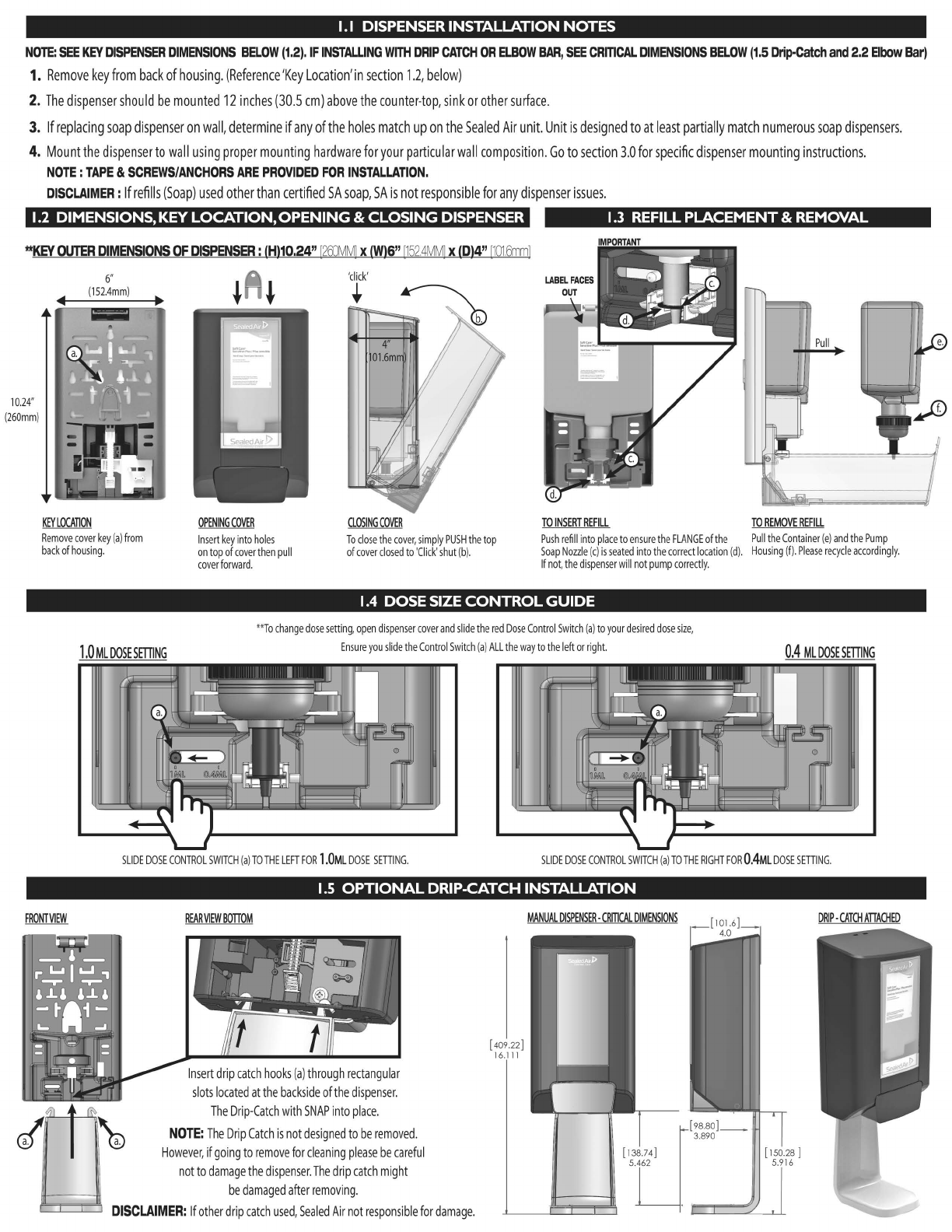
1.
Remove
key
from
back
of
housing.
(Reference
'Key
Location'
in
section
1.
2,
below)
2.
The
dispenser
should
be
mounted
12
inches
(30.5
em)
above
the
counter-top,
sink
or
other
surface.
3.
If
replacing
soap
dispenser
on
wall,
determine
if
any
of
the
holes
match
up
on
the
Sealed
Air
unit.
Unit
is
designed
to
at
least
partially
match
numerous
soap
dispensers.
4.
Mount
the
dispenser
to
wall
using
proper
mounting
hardware
for
your
particular
wall
composition
.
Go
to
section
3.0
for
specific
dispenser
mounting
instructions.
NOTE
:
TAPE
&
SCREWS/ANCHORS
ARE
PROVIDED
FOR
INSTALLATION.
DISCLAIMER:
If
refills
(Soap)
used
other
than
certified
SA
soap,
SA
is
not
responsible
for
any
dispenser
issues.
1.2
DIMENSIONS, KEY
LOCATION,
OPENING
&
CLOSING
DISPENSER
1.3
REFILL PLACEMENT & REMOVAL
**KEY
OUTER
DIMENSIONS
OF
DISPENSER
:
1Hl10.24"
1
2fD'v1M
l x
1Wl6"
I1
52.4MM
J x
IDI4''
[1
01
.
6mm
l
10.24
"
{260
mm
)
6"
{
152.4mm
)
KEY
LOCATION
Remove
cover
key
{a)
from
back
of
housing.
1.0
ML
DOSE
SETIING
OPENING
COVER
Insert
key
into
holes
on
top
of
cover
then
pull
cover
for
wa
rd.
'
click
'
•
CLOSING
COVER
To
close
the
cover,
simply
PUSH
the
top
of
cover
closed
to
'
Click
'
shut
{b
).
TO
INSERT
REFILL
TO
REMOVE
REFILL
Push
refill
into
place
to
ensure
the
FLANGE
of
the
Pull
the
Container
{e)
and
the
Pump
Soap
Nozzle
{c)
is
seated
into
the
correct
location
{d
).
Housing
(f).
Please
recycle
accordingly.
If
not
,
the
dispenser
w
ill
not
pump
correctly.
1.4
DOSE SIZE
CONTROL
GUIDE
**
To
change
dose
setting,
open
dispenser
cover
and
slide
the
red
Dose
Control
Switch
{a)
to
your
desired
dose
size
,
Ensure
you
slide
the
Control
S
wi
tch
{a)
ALL
the
way
to
the
left
or
right.
0.4
ML
DOSE
SETIING
SLIDE
DOSE
CONTROL
SW
ITCH
{a
)TO
THE
LEFTFOR
1.0ML
DOSE
SETIING.
SLIDE
DOSE
CONTROL
SW
ITCH
{a
)TO
THE
RIGHT
FOR
0.4ML
DOSE
SETIING.
1.5
OPTIONAL
DRIP-CATCH INSTALLATION
Insert
drip
catch
hooks
(a)
through
rectangular
slots
located
at
the
backside
of
the
dispenser.
The
Drip-Catch
with
SNAP
into
place.
NOTE:
The
Drip
Catch
is
not
designed
to
be
removed
.
However,
if
going
to
remove
for
cleaning
please
be
careful
not
to
damage
the
dispenser.
The
drip
catch
might
be
damaged
after
removing.
DISCLAIMER:
If
other
drip
catch
used,
Sealed
Air
not
responsible
for
damage.
[ 409.22]
16.111
no.S-2
no.S-1 @
QQ
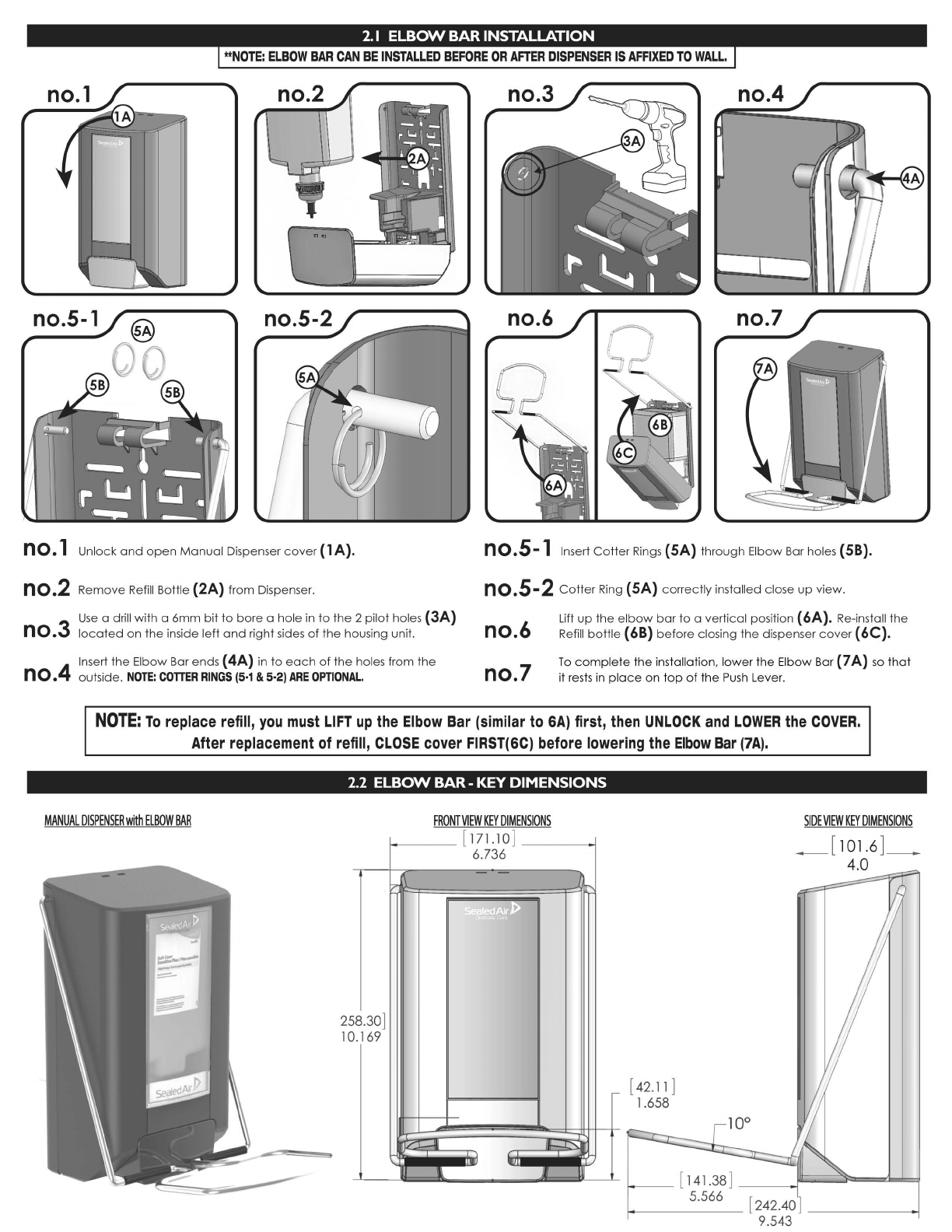
n0.1 Unlock
and
open
Manual
Dispenser
cover
(1
A).
n0.2 Remove
Refill
Bottle (2A) from Dispenser.
Use
a drill with a
6mm
bit
to
bore
a hole
in
to
the 2 pilot holes (3A)
no.3
located
on
the
inside left
and
right sides
of
the
hou
sing unit.
4 Insert
the
Elbow Bar ends ( 4A) in
to
each
of
the
holes from
the
n
0.
outside.
NOTE:
COTTER
RINGS
(5·1
& 5·2)
ARE
OPTIONAL.
no.4
no.7
no.S-1 Insert
Cotter
Rings
(SA) through Elbow Bar holes (58).
no.S-2
Cotter
Ring (SA)
correc
tly installed close
up
view.
no.6
no.7
Lift
up
the
elbow
bar
to
a vertical position ( 6A). Re-install
the
Refill
bottle
( 68)
before
closing
the
dispenser
cover
( 6C).
To
comp
lete
the
installation, l
owe
r
the
Elb
ow
Bar (7 A)
so
that
it
rests
in pla
ce
on
t
op
of
the
Pu
sh
Le
ver.
NOTE:
To
replace
refill,
you
must
LIFT
up
the
Elbow
Bar
(similar
to
6A)
first,
then
UNLOCK
and
LOWER
the
COVER.
MANUAL
DISPENSER
with
ELBOW
BAR
After
replacement
of
refill,
CLOSE
cover
FIRST(GC)
before
lowering
the
Elbow
Bar
(7A).
2.2
ELBOW BAR- KEY DIMENSIONS
25
10
8.30]
.169
FRONT
VIEW
KEY
DIMENSIONS
[
171
10
]
6.736
SJJ1J
iZC=I\
/t=:!S}'
..1.
Jl.
~
r [
42.11
]
1.658
SIDE
VIEW
KEY
DIMENSIONS
_[
101.6
]_
4.0
r----
[ 141.38]
__
_)===~=:d...J.~
f-----
---
5.
_56_6_ [ 242.40 l
----
----1
9.543
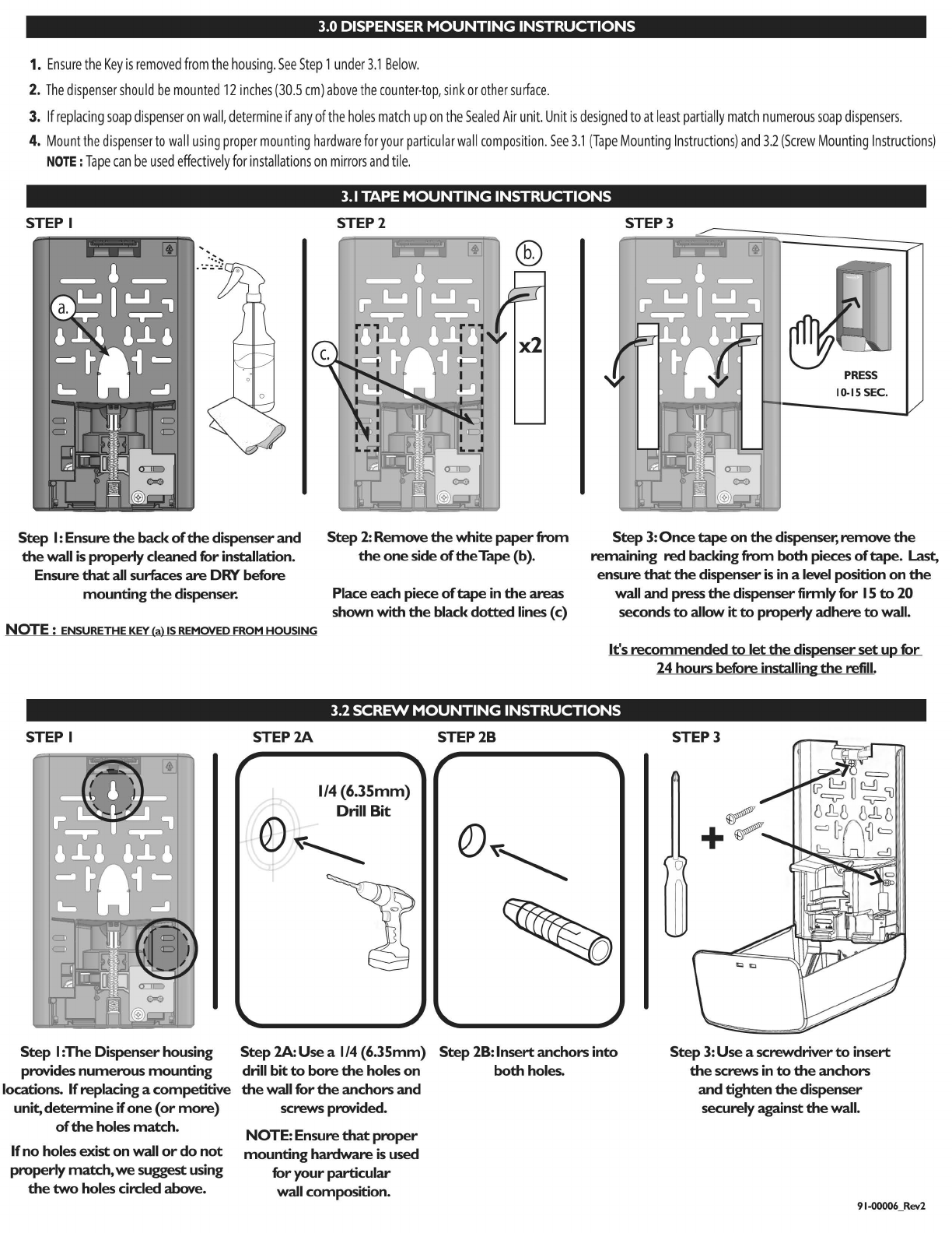
3.0 DISPENSER MOUNTING INSTRUCTIONS
1.
Ensure
the
Key
is
removed
from
the
housing
.
See
Step
1
under
3.1
Below.
2.
The
dispenser
should
be
mounted
12
inches
(30.5
em)
above
the
counter-top,
sink
or
other
surface.
3.
If
replacing
soap
dispenser
on
wall,
determine
if
any
of
the
holes
match
up
on
the
Sealed
Air
unit.
Unit
is
designed
to
at
least
partially
match
numerous
soap
dispensers.
4.
Mount
the
dispenser
to
wall
using
proper
mounting
hardware
for
your
particular
wall
composition
.
See
3.1
(Tape
Mounting
Instructions)
and
3.2
(Screw
Mounting
Instructions)
NOTE:
Tape
can
be
used
effectively
for
installations
on
mirrors
and
tile.
3.1
TAPE MOUNTING INSTRUCTIONS
STEP I
Step
I:
Ensure
the
back
of
the
dispenser and
the
wall
is
properly cleaned for installation.
Ensure
that
all
surfaces
are
DRY
before
mounting
the
dispenser.
NOTE : ENSURETHE KEY
(a)
IS
REMOVED FROM
HOUSING
STEP I
STEP2A
STEP2
Step
2:
Remove
the
white
paper
from
the
one
side
of
the
Tape (b).
Place each piece
of
tape
in
the
areas
shown with
the
black
dotted
lines (c)
STEP3
Step
3:
Once
tape
on
the
dispenser, remove
the
remaining
red
backing from both pieces
of
tape.
Last,
ensure
that
the
dispenser
is
in
a level position
on
the
wall
and
press
the
dispenser firmly for
15
to
20
seconds
to
allow it
to
properly
adhere
to
wall.
It's
recommended
to
let
the
dispenser
set
up for
24 hours before installing
the
refill.
3.2
SCREW
MOUNTING INSTRUCTIONS
STEP2B
r
1/4
(6.35mm)
Drill Bit
0~--
Q
Step
I :The Dispenser housing
provides
numerous
mounting
locations.
If
replacing a competitive
unit,
determine
if
one
(or
more)
of
the
holes
match.
Step
2A:Use a
1/4
(6.35mm)
Step
2B:Insertanchors into
Step
3:
Use a screwdriver
to
insert
the
screws
in
to
the
anchors
and tighten
the
dispenser
securely against
the
wall.
If
no
holes exist
on
wall
or
do
not
properly
match,
we
suggest using
the
two
holes circled above.
drill bit
to
bore
the
holes
on
both
holes.
the
wall for
the
anchors
and
screws provided.
NOTE: Ensure
that
proper
mounting hardware
is
used
for
your
particular
wall composition.
91-00006
_
Rev2
Soap Dispenser Placement Requirements and
Recommendations
(See dispenser instructions in dispenser package for actual dispenser installation)
The following recommendations are intended to provide guidelines on best possible placement of
handsoap dispensers. Because every location a dispenser is to be mounted is different,
depending on customer site, physical size limitations, and available space, these
recommendations may not always be entirely possible to follow. However, when placing a soap
dispenser, the dispenser installation must meet ADA requirements and should promote ease of
use and be in union with its surroundings. Upon installation, the dispenser should be level and
the job results professional, presentable, and fully functional.
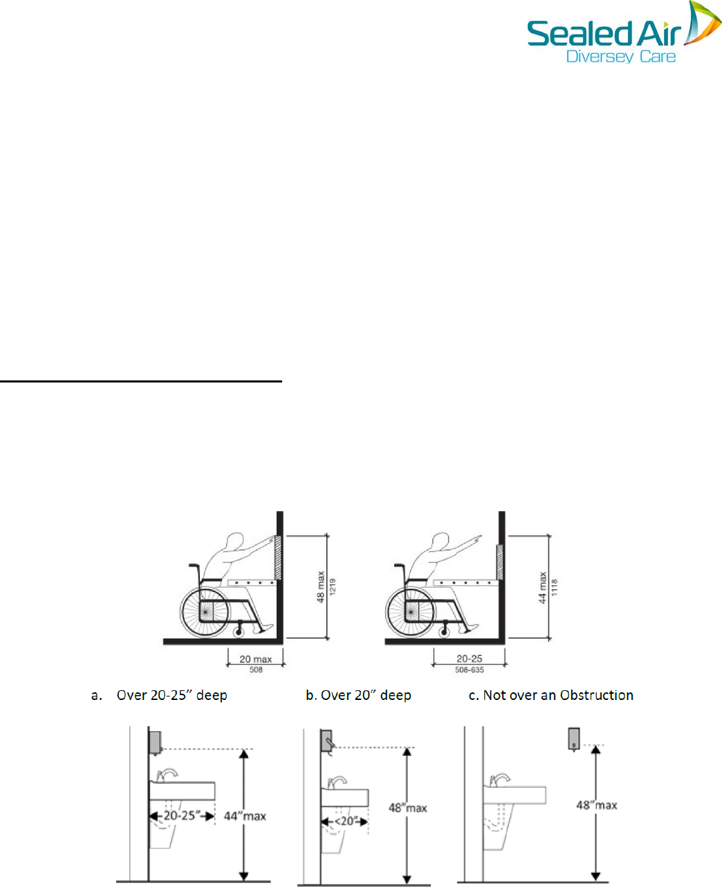
Requirements for ADA Compliance:
The dispenser must be operable with one hand.
Minimum height requirements reference the height of the activator mechanism.
o Maximum height is 48” when vanity is 20” (or less) deep.
o Maximum height is 44” when vanity is 20”-25” deep.

Restrooms
Installation must be ADA compliant.
Whenever possible, always mount the soap dispenser direct to a wall instead of a mirror or
other installed fixture.
o Always use screws to attach dispenser to wall when wall mounted.
Anytime space is available, mount dispenser just to the left or right of a mirror.
o Leave about 1/4" to 1/2" space between mirror and dispenser - just enough for it to
open/shut freely and without obstruction.
o IntelliCareTM Hybrid Dispenser’s must be mounted a minimum of 12 inches (30.5 cm)
between the bottom of the dispenser and any horizontal surface to assure proper
operation of the dispenser. (Be sure dispenser is still meeting ADA height
requirements)
When installing dispensers for sink modules with multiple wash basins, use good judgment
when determining how many dispensers should be installed. A single dispenser should be
sufficient in serving a module with two wash basins, while 2 dispensers should be sufficient
to serve a module with 3 wash basins.
o See enclosed examples for placement ideas.
Install only on a mirror when all other possibilities have been exhausted.
Food Service Areas
It is recommended to always mount a soap dispenser direct to a wall instead of the sink’s
backsplash whenever possible.
o Always use screws to attach dispenser to wall when wall mounted.
Anytime space is available, mount dispenser just to the left or right of the sink.
o Leave about 1/4" to 1/2" space between sink and dispenser - just enough for it to
open/shut without hitting the sink).
o IntelliCareTM Hybrid Dispenser’s must be mounted a minimum of 12 inches (30.5 cm)
between the bottom of the dispenser and any horizontal surface to assure proper
operation of the dispenser. (Be sure dispenser is still meeting ADA height
requirements)
Avoid mounting a dispenser too high or too low. Always attempt to mount in close
proximity of the actual use area.
Do not install a hand soap dispenser directly above any surface where food will be
prepared.
In food service areas, a hand soap dispenser (and soap) is required at every hand wash
sink.
Install only on the sink backsplash when all other possibilities have been exhausted.
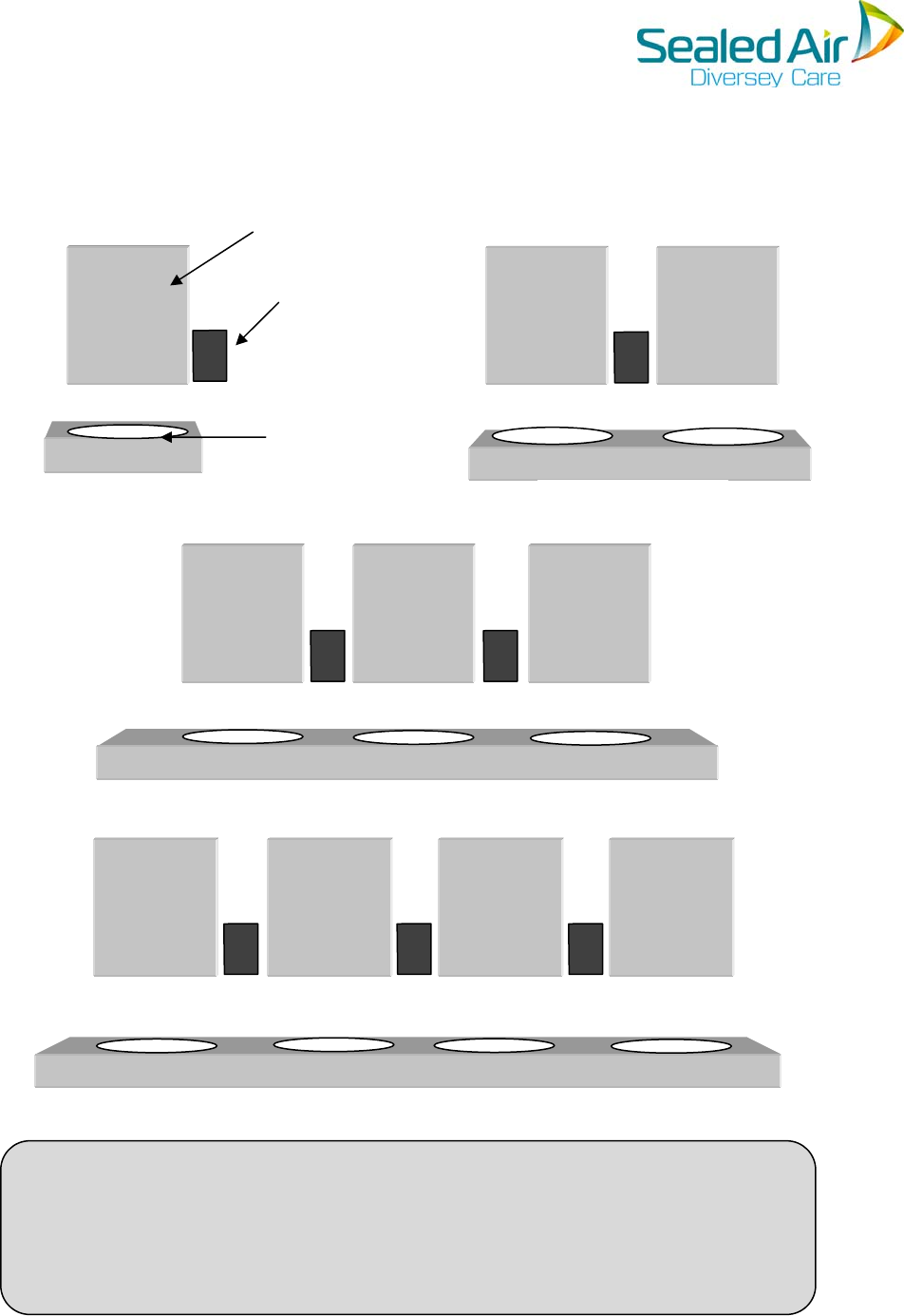
InstallationExamplesforRestrooms
HelpfulTip:Installingthedispenserinlinewiththebottomofthemirror
(mountedoverthelavatory)isalwaysrecommended.Ifthemirrorisinstalled
incompliancewithADArequirements(bottomofmirrormax40”abovefloor),
thehandsoapdispenserwillbeinADAcompliance.Aswell,thisinstallation
createsacleanersightlinethanotheroptions.
TripleSink
SingleSink
(Familyrestroom)
Dispenser
Mirror
WashBasin
DoubleSink
QuadrupleSink

FCCLabelingRequirements
Thisdevicecomplieswithpart15oftheFCCRules.Operationissubjecttothefollowing
twoconditions:(1)Thisdevicemaynotcauseharmfulinterference,and(2)thisdevice
mustacceptanyinterferencereceived,includinginterferencethatmaycauseundesired
operation.
Anyintentionalorunintentionalradiatorshallcautiontheuserthatchangesor
modificationsnotexpresslyapprovedbythepartyresponsibleforcompliancecould
voidtheuser’sauthoritytooperatetheequipment.
Thisdevicecomplieswithpart15oftheFCCRules.Operationissubjecttothecondition
thatthisdevicedoesnotcauseharmfulinterference.
This device has been tested according to FCC RF Exposure guidelines and meets the
applicable RF Exposure limits with all the intended use conditions for this device.
©Diversey,Inc2017