1c Sitraffic S X Service Manual Controller Technology A001a En
User Manual:
Open the PDF directly: View PDF ![]() .
.
Page Count: 152 [warning: Documents this large are best viewed by clicking the View PDF Link!]
- 1. Technical concept
- 1.1. The modular hardware concept
- 1.2. Sitraffic sX
- 1.3. Key data for cabinets
- 1.4. Frame
- 1.6. Structure of Sitraffic sX-H
- 1.7. Basic version sX-H
- 1.8. Additions
- 1.9. Schematic representation of main chassis
- 1.10. Schematic representation of add-on chassis
- 1.11. Switch-off route
- 1.12. 230 -V distribution
- 1.13. Utility compartment
- 1.14. Power distributor
- 1.15. Power consumption of sX-H
- 2. Components
- 2.1. Power connection
- 2.2. Power supplies
- 2.3. CBU
- 2.4. CMD
- 2.5. CTB
- 2.6. CEB
- 2.7. OMC-U
- 2.8. CPDH
- 2.9. LED switch LSHS
- 2.10. CEW module
- 2.11. CDBH
- 2.12. CPA module
- 2.13. sX-Hx device
- 2.14. CLB installation locations
- 2.15. CLB
- 2.16. CLBT module
- 2.17. CLA module
- 2.18. SLD4 loop detector module
- 2.19. IO module CIE//CIO
- 2.20. Wimag activation
- 2.21. Video detectors
- 2.21.1. DIB-E
- 2.21.1.1. Setting DIB-E address in the CLB
- 2.21.1.2. DIB-E Front
- 2.21.1.3. Head connector
- 2.21.1.4. USB port
- 2.21.1.5. Ethernet port
- 2.21.1.6. LED description
- 2.21.1.7. Connection of the SIVICAMs
- 2.21.1.8. Topologies of the networks to be connected to the SIVICAMs
- 2.21.1.9. Power supply of the cameras
- 2.21.1.10. DIB-E activation at the CLB
- 2.21.1.11. DIB-E activation at the CBU
- 2.21.1.12. Additional Information
- 2.21.1. DIB-E
- 2.22. 230 V pedestrian request / pedestrian confirmation CIAC/CIAB
- 2.22.1. Setting CIAB address
- 2.22.2. Structure of CIAB
- 2.22.3. Terminal assignment for CIAB
- 2.22.4. CIAC breakdown
- 2.22.5. CIAC LED meaning
- 2.22.6. CIAC head connector (X2)
- 2.22.7. External input
- 2.22.8. Output
- 2.22.9. CIAB activation internally 230 V
- 2.22.10. Activation button for confirmation devices 230 V
- 2.22.11. CIAB connection, internal for signal heads for the visually impaired
- 2.23. BAZ operating unit
- 2.24. Alternative command device
- 2.25. CCU GPS internal
- 2.26. CCUE GPS External
- 2.27. PT preference (AFD)
- 2.28. Supplementary power supply 24V DC
- 2.29. Supplementary power supply 24V AC
- 2.30. Cabinet heater
- 2.31. Control center activation
- 2.32. UPS (USC is optional)
- 2.33. Special adapter CUA
- 3. Diagnostics
- 4. Technical data
- 5. Part numbers, modules
- 6. Part numbers for installation sets
- 7. Abbreviations
- 8. Index

Sitraffic sX
Service manual, controller technology 1c
A001a
Intelligent Traffic Systems

Sitraffic sX
Service manual controller technology 2
Siemens AG V1.0 A001a / 2014-08-20
Contents
1. Technical concept 10
1.1. The modular hardware concept 10
1.2. Sitraffic sX 12
1.3. Key data for cabinets 14
1.4. Frame 16
1.5. sX-H power supply connection/fuses/ 17
1.6. Structure of Sitraffic 10-H 18
1.7. Basic version sX-H 20
1.8. Additions 21
1.9. Schematic representation of main chassis 22
1.10. Schematic representation of add-on chassis 23
1.11. Switch-off route 23
1.12. 230 -V distribution 25
1.13. Utility compartment 25
1.14. Power distributor 27
1.15. Power consumption of sX-H 29
2. Components 30
2.1. Power connection 30
2.2. Power supplies 30
2.3. CBU 31
2.3.1. Operating principle of the CBU 31
2.3.2. Control unit 34
2.3.3. Signal monitoring unit 35
2.3.4. Plug connector and interfaces of the CBU 38
2.3.5. Display and control elements of the CBU 40
2.4. CMD 44
2.4.1. Reset of the CBU 45
2.4.2. Setting the operating mode of the CBU 45
2.4.3. Display of operating statuses of the CBC 46
2.5. CTB 46
2.5.1. Assignment of CTB_X5 46
2.5.2. Assignment of CTB_X4 47
2.6. CEB 51
2.7. OMC-U 52
2.8. CPDH 59
2.9. LED switch LSHS 64

Sitraffic sX
Service manual controller technology 3
Siemens AG V1.0 A001a / 2014-08-20
2.10. CEW module 68
2.11. CDBH 69
2.12. CPA module 72
2.12.1. Installation for sX-H and sX-Hx 72
2.13. sX-Hx device 75
2.14. CLB installation locations 78
2.15. CLB 78
2.16. CLBT module 84
2.17. CLA module 85
2.18. SLD4 loop detector module 86
2.18.1. UPLINK/DOWNLINK 88
2.19. IO module CIE//CIO 92
2.19.1. Status LEDs 93
2.19.2. Head connector (CIE/CIO) 93
2.19.3. Base connector/terminal block (CIE/CIO) 94
2.20. Wimag activation 97
2.21. Video detectors 98
2.21.1. DIB-E 98
2.22. 230 V pedestrian request / pedestrian confirmation CIAC/CIAB 108
2.22.1. Setting CIAB address 110
2.22.2. Structure of CIAB 110
2.22.3. Terminal assignment for CIAB 111
2.22.4. CIAC breakdown 111
2.22.5. CIAC LED meaning 112
2.22.6. CIAC head connector (X2) 113
2.22.7. External input 113
2.22.8. Output 114
2.22.9. CIAB activation internally 230 V 115
2.22.10. Activation button for confirmation devices 230 V 116
2.22.11. CIAB connection, internal for signal heads for the visually
impaired 117
2.23. BAZ operating unit 119
2.23.1. BAZ installation, internal 120
2.23.2. External BAZ 120
2.24. Alternative command device 122
2.25. CCU GPS internal 122
2.26. CCUE GPS External 123
2.27. PT preference (AFD) 124
2.28. Supplementary power supply 24V DC 124
2.29. Supplementary power supply 24V AC 127
2.29.1. Activation 128
2.30. Cabinet heater 129
2.31. Control center activation 130

Sitraffic sX
Service manual controller technology 4
Siemens AG V1.0 A001a / 2014-08-20
2.31.1. UMTS Router 130
2.31.2. Canto P (DSL activation) 132
2.32. UPS (USC is optional) 136
2.33. Special adapter CUA 137
3. Diagnostics 138
4. Technical data 139
4.1. Standards 139
4.2. Characteristics of hardware and general 140
5. Part numbers, modules 145
6. Part numbers for installation sets 146
7. Abbreviations 148
8. Index 150

Sitraffic sX
Service manual controller technology 5
Siemens AG V1.0 A001a / 2014-08-20
List of figures
Fig. 1: Main chassis (left), main chassis with add-on chassis (right) 10
Fig. 2: Frame structure for sX-H and sX-Hx 11
Fig. 3: Cabinets for Main and Expansion frames 14
Fig. 4: 3O/N cabinet 15
Fig. 5: sX Structure 18
Fig. 6: Block diagram of main chassis 1 22
Fig. 7: Block diagram of add-on chassis 1 and 2 23
Fig. 8: Switch-off route 24
Fig. 9: 230 -V distribution 25
Fig. 10: Utility compartment of sX-H (single-phase/2-phase) 26
Fig. 11: Pattern of power distributor 28
Fig. 12: Block diagram of the CBU 31
Fig. 13: Plug connector of the CBU 38
Fig. 14: Display and control elements of the CBU 40
Fig. 15: LED array of the CBU 41
Fig. 16: Display and control elements of the CMD 44
Fig. 17: Indicator plate for CTB module 50
Fig. 18: View of CTB module 50
Fig. 19: CEB view 51
Fig. 20: OMC-U top side 53
Fig. 21: OMC-U bottom side 54
Fig. 22: PL6 assignment 56
Fig. 23: OMC-U front side 56
Fig. 24: Position of the jumpers on the OMC 57
Fig. 25: Placing the dongle in the retainer of the OMC 58
Fig. 26: Identification of the rotary switch position of the OMC 58
Fig. 27: CPDH assignment 60
Fig. 28: CPDH_X4 EMERGENCY OFF setting 62
Fig. 29: View of LSHS fuses 65
Fig. 30: LSHS fuse assignment 67
Fig. 31: CEW next to LSHS 68
Fig. 32: Photo CDBH X15 (here address 5 set) 70
Fig. 33: CDBH view 70
Fig. 34: Sample wiring of the digital inputs 72
Fig. 35: Photo CPA CDBH connection 73
Fig. 36: Activation of CPA-CDBH 74
Fig. 37: Wire C24700-K10-B181 76
Fig. 38: Fuse connection sX-Hx 76
Fig. 39: Installation of 2nd CPDH 77
Fig. 40: CLB housing (configuration example) 82
Fig. 41: CLBT module 84

Sitraffic sX
Service manual controller technology 6
Siemens AG V1.0 A001a / 2014-08-20
Fig. 42: CLA structure 85
Fig. 43: CLA module installed 86
Fig. 44: Loop activation 88
Fig. 45: Schematic structure uplink / and downlink 90
Fig. 46: CLB method of counting in main chassis 91
Fig. 47: Maximum CLB assembly 92
Fig. 48: Confirmation devices and buttons with +24V 96
Fig. 49: WIMAG activation 97
Fig. 50: DIB-E front side 99
Fig. 51: Connector terminals of the SIVICAM 102
Fig. 52: Description of the connection terminals of the SIVICAM 103
Fig. 53: Possible topologies for the connection of the cameras 104
Fig. 54: DIP-E power supply for cameras 105
Fig. 55: CIAB/CIAC structure 109
Fig. 56: CIAC breakdown 112
Fig. 57: CIAB activation, internal 115
Fig. 58: Connection button/confirmations 116
Fig. 59: Activation of signal heads for visually impaired, internal 118
Fig. 60: BAZ 119
Fig. 61: Block diagram BAZ external 120
Fig. 62: Installation TEB_BAZ_external 121
Fig. 63: CCU assembly 122
Fig. 64: CCUE_TEB installation 123
Fig. 65: CCUE_TEB activation 124
Fig. 66: Activation of DC power supply 125
Fig. 67: Mounting power supply 126
Fig. 68: Installation of the DC power supply 127
Fig. 69: Activation of AC power supply 128
Fig. 70: Installation of the AC power supply 128
Fig. 71: Activation of heater set 129
Fig. 72: View of cabinet heater 129
Fig. 73: Activation of UMTS Router 130
Fig. 74: UMTS router installation 131
Fig. 75: Mounting UMTS antenna 131
Fig. 76: Canto P modem configuration 132
Fig. 77: Installation of Mini-Flex modem 133
Fig. 78: Mini Flex connection in the device 134
Fig. 79: SHDL pinout for Mini Flex modem 134
Fig. 80: Pinout for power supply of Mini Flex modem 135
Fig. 81: Meaning of the LEDs with the Mini Flex modem 135
Fig. 82: Figure of CUA e.g. with 1x BFU module 137

Sitraffic sX
Service manual controller technology 7
Siemens AG V1.0 A001a / 2014-08-20
List of tables
Tab. 1: sX-H power supply connection/fuses 17
Tab. 2: Components of the sX controller 20
Tab. 3: Power distributor assignment 27
Tab. 4: Power consumption 29
Tab. 5: Explanations for block diagram of the CBU (see Fig. 12) 33
Tab. 6: Description of the plug connector of the CBU, see Fig. 13 39
Tab. 7: Description of the display and control elements of the CBU (see Fig.
14) 41
Tab. 8: Identification of the LEDs of the processors CBC, CHX and CMU 42
Tab. 9: Meaning of the LEDs of the processors CBC, CHX and CMU 43
Tab. 10: Meaning of the LEDs for primary alarm 43
Tab. 11: Meaning of the LEDs for secondary alarm 43
Tab. 12: Meaning and function of the display and control elements of the
CBU 44
Tab. 13 Rotary switch functions 46
Tab. 14: Assignment of the X5 terminal block of the CTB 47
Tab. 15: Assignment of the terminal block X4 of the CTB 48
Tab. 16: Load capacity of the power supply outputs of the CTB 49
Tab. 17: CEB connector 52
Tab. 18: CF card part numbers 53
Tab. 19: Description of OMC-U top side (see Fig. 20) 54
Tab. 20: Description of OMC-U bottom side (see Fig. 21) 55
Tab. 21: Pinout OMC_PL6 55
Tab. 22: Description of OMC-U front side (see Fig. 23) 57
Tab. 23: Jumper setting for OMC 58
Tab. 24: CPDH configuration 59
Tab. 25: CPDH connector/fuse 61
Tab. 26: Pinout CPDH_X1 61
Tab. 27: Pinout CPDH_X6 62
Tab. 28: Pinout CPDH_X10 62
Tab. 29: Pinout CPDH_X11 63
Tab. 30: Pinout CPDH_X12 63
Tab. 31: Pinout CPDH_X19 DIMM connector 63
Tab. 32: CDBH address setting 69
Tab. 33: CDBH view 71
Tab. 34: CDBH X6 assignment 71
Tab. 35: CDBH X7 assignment 72
Tab. 36: Fuse connection sX-Hx 77
Tab. 37: Installation of 2nd CPDH 78
Tab. 38: CLB installation locations 78
Tab. 39: Setting of the addresses with IO bus 1 80

Sitraffic sX
Service manual controller technology 8
Siemens AG V1.0 A001a / 2014-08-20
Tab. 40: Setting of the addresses with IO bus 2 81
Tab. 41: CLB with configuration example 82
Tab. 42: CLB inscription 83
Tab. 43: CLB configuration 84
Tab. 44: Terminal assignment of the CLB when SLD4 equipped 87
Tab. 45: CIE/CIO breakdown 93
Tab. 46: CIE/CIO LED Information 93
Tab. 47: CIE/CIO assignment for head connector 94
Tab. 48: CIE/CIO input data 95
Tab. 49: CIE/CIO Output data 95
Tab. 50: Description of DIB-E front side ( see Fig. 50 99
Tab. 51: DIB-E front connector 100
Tab. 52: DIB-E LED meaning 101
Tab. 53: Assignment of the connecting cable for the SIVICAMs 102
Tab. 54: Network topologies for SIVICAMs 103
Tab. 55: DIB-E connection assignment CLB 106
Tab. 56: DIB-E connection assignment CTB 107
Tab. 57: Technical limit values 108
Tab. 58: Structure of CIAB/CIAC 110
Tab. 59: Terminal inscription CIAB/CIAC 111
Tab. 60: CIAC Fuses 112
Tab. 61: CIAC LED Function1 113
Tab. 62: CIAC LED Function2 113
Tab. 63: CIAC input data 114
Tab. 64: CIAC output data 115
Tab. 65: Activation of BAZ external 121
Tab. 66: Connection terminals for alternative command device. 122
Tab. 67: Mounting parts for power supply 126
Tab. 68: Terminals of the CTB connection to the USC 136
Tab. 69: Meaning of the signals for the connection of a USC. 136
Tab. 70: Standards 139
Tab. 71: Module part numbers 145
Tab. 72: Set part numbers 147

Sitraffic sX
Service manual controller technology 9
Siemens AG V1.0 A001a / 2014-08-20
Introduction
Notes on safety and environmental protection
Safety notice
The devices/systems are only to be employed for their intended use in
accordance with the product documentation; the warning labels and
product documentation are to be adhered to. The installation and initial
startup of the devices may only be performed by authorized professional
personnel (electrically qualified persons with the appropriate training for
these devices/systems through the Siemens Academy, Traffic Systems
Segment).
If not sufficiently trained personnel are working on the devices, substantial
bodily damage and property damage can come as a consequence.
The devices/systems are to be tested regularly by authorized professional
personnel. The test intervals and the checks to be performed can be found
in the specifications of the product standards. If there are no product
standards with information about regular checks for the devices, then the
tests are to be performed in accordance with the standards IEC 60364-6,
EN 50110 Row, HD 60364-6: 2007 article 62 and EN 50556 table 2.
Occupational safety, environmental protection
It goes without saying that all legal regulations regarding occupational
safety and environmental protection are to be complied with during the
course of production. We design our products (parts, devices, systems) in
such a way that these present no health hazards to the user or hazards the
environment according to the current state of information if properly and
predictably used.
Recycling, disposal
The information above makes it possible to assess to a large extent the
possible potential for hazards to people and the environment, even at the
end of the product's life cycle. The regulations for recycling and disposal
procedures must be observed here.
All information has been given to the best of our knowledge and belief. It is
in accordance with the current state of the art. The information does not
constitute a guarantee in the legal sense of a warranty.
Sitraffic sX
Service manual controller technology 10
Technical concept
Siemens AG V1.0 A001a / 2014-08-20
1. Technical concept
Concentration on the essentials—with aspiration Siemens has developed a
new generation of traffic control technology. Here, the focus is perfection
of the commonplace and in connection with this the facilitation of
handling with the usual functionality. The result is the innovative traffic
controller, the Siemens Sitraffic smartX (sX).
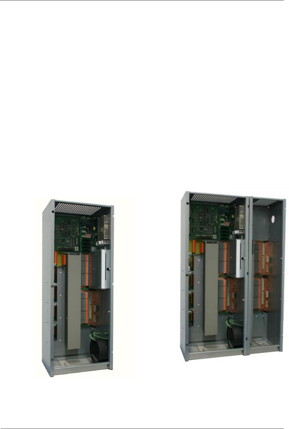
1.1. The modular hardware concept
For the new Sitraffic sX, an entirely new concept was developed for both
the hardware as well as the software and its tools. The idea of the modular
frame concept is that depending on requirements the basic frame can be
supplemented with additional add-on chassis.
sX for up to 16
signal groups sX for up to 32 signal groups
Fig. 1: Main chassis (left), main chassis with add-on chassis (right)
Sitraffic sX
Service manual controller technology 11
Technical concept
Siemens AG V1.0 A001a / 2014-08-20
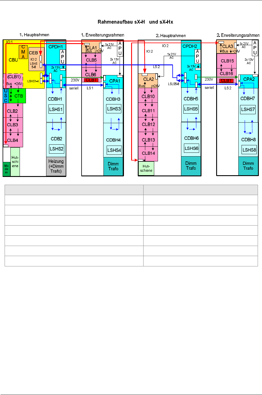
German English
Rahmenaufbau Frame construction
Hauptrahmen Main frame
Erweiterungsrahmen Add-on frame
Seriell serial
Hutschiene Top-hat rail
Heizung Heating
Dimm Trafo Dimming transformer
Fig. 2: Frame structure for sX-H and sX-Hx
The sX-H consists only of the first main chassis/first add-on chassis in the
first cabinet.
For the sX-Hx controller, in the second cabinet there is also another second
main chassis and if necessary the second add-on chassis.

Sitraffic sX
Service manual controller technology 12
Technical concept
Siemens AG V1.0 A001a / 2014-08-20
1.2. Sitraffic sX
sX is a controller for traffic signaling devices. A motherboard with the
name CBU forms the core of the controller. On the motherboard there are
modules of the plug-in type, which are used for signal monitoring and the
detection of vehicles and pedestrians. There are LED switch modules
(LSHS) for 230 V LED plug-in signal head.
The version of the sX controller with 230V LED switches is called sX-H.
In order to construct a small controller, the following components are built
into the sX-H controller:
■Motherboard CBU equipped with the following components:
□Processor module OMC and processor module CBC for signal
control
□Processor modules CHX and CMU for signal monitoring
□Mode module CMD for the selection of the operating mode for
signal monitoring
■Backplane CTB with spring terminals for connecting request keys and
confirmation devices to the CBU.
■Power supply for CBU, CMD and OMC.
■Backplane CBDH with multipin sockets for receiving an LED switch
LSHS and with spring terminals for the connection of the signal heads.
■LED switch LSHS
■Power supply APU for the logic of the LED switch
■Power supply and monitoring CPDH for the LED signal heads of the
outdoor system
All modules are directly plugged into each other via plug connections. No
drop cables are needed in the basic version.
With this construction for a small controller the status of the 8 request keys
can be monitored; moreover, 8 confirmation devices and 8 signal groups
can be activated.

Sitraffic sX
Service manual controller technology 13
Technical concept
Siemens AG V1.0 A001a / 2014-08-20
If two detector modules SLD4 are plugged into the two installation
locations intended for them X39 and X40 of the CBU, 8 additional
induction loops can be monitored. Alternatively, IO modules can be
inserted into these installation locations in order to be able to connection
additional request keys or confirmation signals. Contact of the CBU signals
to the outdoor system is established via spring terminals on the CTB
module.
The CBU installation locations X39 and X40 are connected to the
microprocessor module CBC on the CBU via a serial IO bus. All IO and
detector modules that were developed for the sX controller have an
interface for this IO bus. There are 2 identical IO busses, called IO1 and IO2.
The IO busses are RS422 busses for which all the bus participants are
switched in parallel. By attaching CLB backplanes to the CTB backplane, the
IO1 bus can be extended. Up to 8 CLB can be connected to the IO1 bus,
one after another. In the basic version, only the IO1 bus is present. An
optional IO2 bus allows another 8 CLB modules in another cabinet.
Therefore, a total of up to 16 CLB modules can be reached.
Each CLB has two installation locations for IO modules or detectors. For
connecting the outdoor system the necessary spring clips are available on
the CLB.
Also the LED switches have a serial RS 422 bus. It is called LS1 and LS2. Up
to 4 LED switches can be connected per LS bus. Only LS1 is available in the
basic version. The LS busses have a point-to-point connection.
Both the LS bus as well as the IO2 bus requires the interface expansion
module CEB. It is not included in the basic version.
Sitraffic sX
Service manual controller technology 14
Technical concept
Siemens AG V1.0 A001a / 2014-08-20
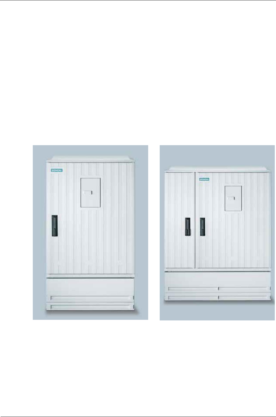
1.3. Key data for cabinets
The main frame and the expansion frame can be installed in the similar
design cabinets manufactured by
■Orlite (O) and
■NKT (N)
from the factory and mounted to known standard bases. Depending on
whether only the main frame or multiple frames are required, cabinets are
available with different dimensions and with one or two doors.
1O/N cabinet for one main frame
(incl. EVU) 2O/N cabinet for main and expansion
frames (incl .EVU)
Fig. 3: Cabinets for Main and Expansion frames
A main frame can be installed in a 1O/N cabinet together with the standard
EVU component (for power supply). This has the following dimensions,
depending on the manufacturer
■806 x 380 x 1100 mm³ (W x D x H) for type 1N or
■785 x 380 x 1100 mm³ (W x D x H) for type 1O.
Sitraffic sX
Service manual controller technology 15
Technical concept
Siemens AG V1.0 A001a / 2014-08-20
The combination of a main and expansion frame can be installed in a 2O/N
cabinet with the dimensions
■1136 x 380 x 1100 mm³ (W x D x H) for type 2N or
■1115 x 380 x 1100 mm³ for type 2O.
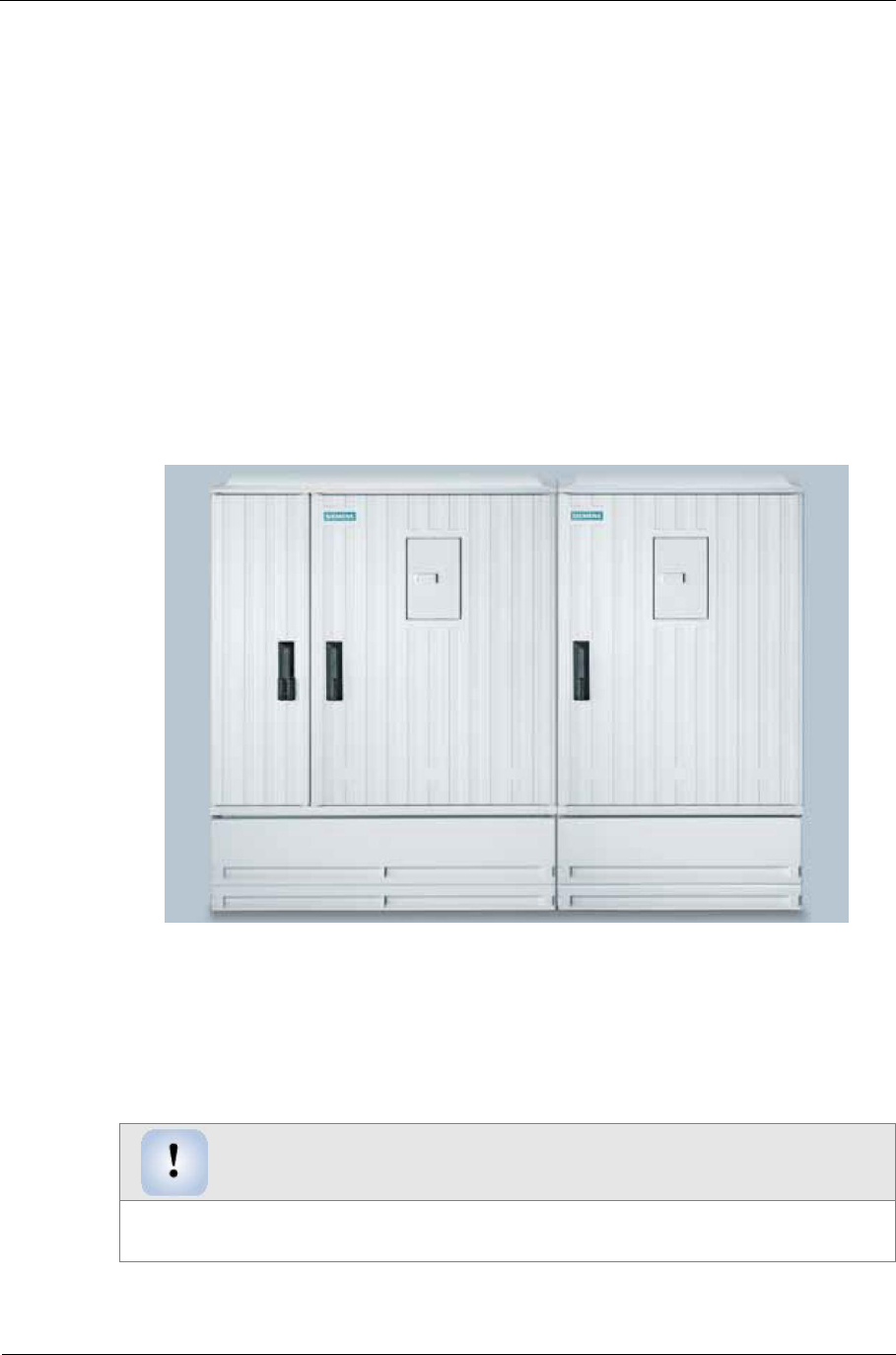
A second main and expansion frame can be installed in an additional
cabinet. This combination results in a 3O/N cabinet (see Fig. 4) with the
dimensions
■1902 x 380 x 1100 mm (W x D x H) as type 3N or
■1900 x 380 x 1100 mm³ (W x D x H) as type 3O.
Fig. 4: 3O/N cabinet
Additionally, all variants feature a small operating door in one of the
cabinet doors behind which an operating and display unit is located.
Assembly tools
For all parts of the controller you must use Torx screws.
Suitable tools must be used.

Sitraffic sX
Service manual controller technology 16
Technical concept
Siemens AG V1.0 A001a / 2014-08-20
1.4. Frame
For housing the components of the sX controller a broad principle add-on
chassis and a narrow add-on chassis were developed. This makes it possible
to install the main chassis in a 1N or 1O cabinet. This way up to 16 signal
groups can be handled in a 1O or 1N cabinet.
The following components are located in the main chassis:
■Power distributor with fuses
■Processors of the signal controller
■Processors of the signal monitor
■Vehicle detectors
■IO modules for detecting request signals
■IO modules for activating confirmation devices.
■ 2 units of LED switch modules for 230-V LED modules
■Power supply
Two LED switch modules LSHS can be mounted in the main chassis. Up to
16 signal groups are possible this way.
Two additional LED switch groups LSHS are housed in the add-on chassis.
Therefore, a total of 32 signal groups is possible.
Principle and secondary frames are screwed together. For installing them
into the device cabinet, the frames are mounted onto the rear wall of the
cabinet and screwed together with it.
The device cabinet is positioned on top of a slot. Through it all the ground
cables are guided up from below into the principle and secondary frame.
Spring terminals are provided for connecting the wires.
The IO modules and power supply add-ons have the same dimensions and
can be installed in the same IO module locations.
The add-on chassis is mounted onto the main chassis at the right. The
following parts are necessary for retrofitting:
■Expansion unit or door /C10 L24730-E800-A3
■Front door, large /C10 C24734-A16-B233

Sitraffic sX
Service manual controller technology 17
Technical concept
Siemens AG V1.0 A001a / 2014-08-20
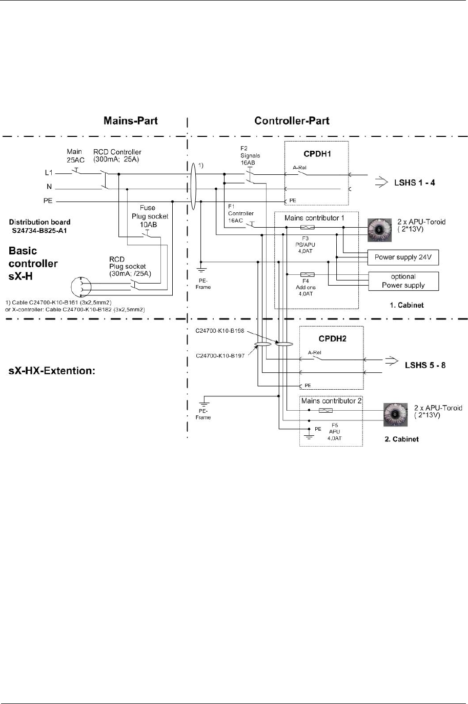
1.5. sX-H power supply connection/fuses/
Requirement Standard
Power supply connection Phase-to-null or phase-to-phase power
grids
Rated voltage of connection
(power supply connection) 230 V AC; - 20 %; +15 %;
also covers 240 V –24 %, + 10 %;
50 Hz +/- 4 %
Power consumption of
control section max. 75 VA at 230 V
typically 28 VA at 230 V
Max. permissible total load 2.76 kW at 230 V per cabinet
Max. continuous / switching
power for each signal group
or
signal circuit
Per output: 72 W ( 4x 18 W)
Per LSHS: 4 A (at 230 V) i.e. 920 W
Earth-leakage circuit
breaker 30 mA for the outlet
300 mA for the device
Insulation monitoring For the outdoor system
Controller fuse Protected by a 25 A fuse in power supply
company's compartment
Maintenance socket and
fuse German variant in power supply company's
compartment for 10A
Fuse for lamp voltage 230 V / 16AB for 4 LSHSs
6.3 A per LSHS on the CPDH
Surge protection Simple surge protection on the power-
supply side
optional: DIN EN 62305 (VDE 0815-305)
Power supply fuse for
auxiliary power supplies 2 units of 4.0 A fuses for power supplies and
add-ons
Power failure bridging time > = 40 ms; briefer power supply faults do
not cause the device to switch off
Tab. 1: sX-H power supply connection/fuses
Sitraffic sX
Service manual controller technology 18
Technical concept
Siemens AG V1.0 A001a / 2014-08-20
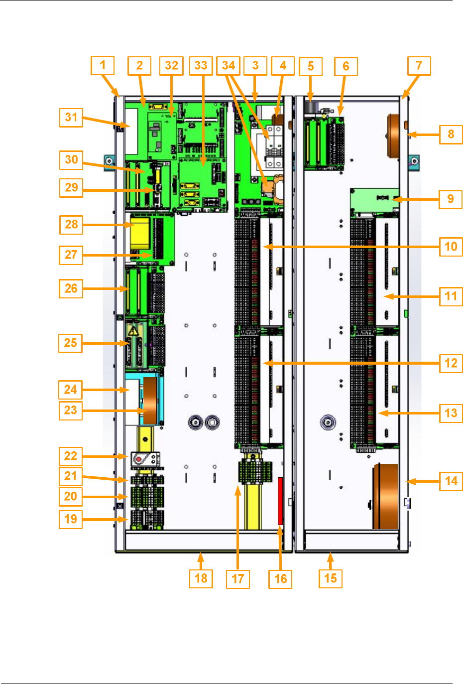
1.6. Structure of Sitraffic sX-H
Fig. 5: sX Structure

Sitraffic sX
Service manual controller technology 19
Technical concept
Siemens AG V1.0 A001a / 2014-08-20
No. Name Description
1-- sX main chassis
2CBU CBU module
3CPDH Power supply for the LED switch LSHS
4APUklein Small transformer, in the main chassis for the logic of the
LSHS
5CLA Voltage controller for IO modules in the add-on chassis
6CLB Backplane for detectors and IO modules
7-- sX add-on chassis
8APUgroß Large transformer, in the add-on chassis for the logic of the
LSHS
9CPA Adds power supply to the lamp switch bus.
10 CBDH CDBH backplane and LED switch LSHS1
11 CBDH CDBH backplane and LED switch LSHS3
12 CBDH CDBH backplane and LED switch LSHS2
13 CBDH CDBH backplane and LED switch LSHS4
14 -- Dimm transformer
15 -- Floor opening for ground cables
16 -- Cabinet heater
17 -- PE terminals for LED switches LSHS3 and 4
18 -- Floor opening for ground cables
19 -- 0V terminals for outdoor system and PE16mm2
20 -- PE terminals for LED switches LSHS1 and 2
21 -- Terminals for telecommunication wires to the control center
22 -- Thermostat for heater
23 -- 24 V AC add-on power supply for confirmation devices
24 -- 24 V DC add-on power supply for modems, detectors
25 CIAB Backplane for CIAC (IO module for alternating current)
26 CLB Backplane for IO modules and detectors
27 CTB Backplane with female multipoint connectors with IOs of the
CBU
28 USC UPS
29 OMC OMC module
30 CMD CMD module
31 24 V power supply for CBU and components
32 CMA CMA module (modem)

Sitraffic sX
Service manual controller technology 20
Technical concept
Siemens AG V1.0 A001a / 2014-08-20
No. Name Description
33 CEB CEB module for IO expansion
34 Power distributor
Tab. 2: Components of the sX controller
1.7. Basic version sX-H
The basic version consists of the following components:
■Power distributor, power supply, APU transformer
■OMC (control module) Ethernet connections
■2 USB ports
■9 serial ports
■1 GB flash (optionally up to 8 GB flash)
■CBU/ CMD (signal monitoring module, power supply)
■8 touch button inputs 24 V DC, 8 confirmation outputs 24 V DC
■2 installation locations on the CBU for IO modules such as SLD4 or
CIE/CIO
■CEB installation location (interface expansion) on the CBU
■CTB (connection terminals of CBU module)
■CPDH (LED voltage monitoring and switch-off, fuse)
■up to 2 units of CDBH/LSHS (backplane with terminals and LED
switches)
■2 CLB installation locations for 2 IO modules each
■Tophat rail for PE-, 0 V terminals
The combinations shown give an idea of the variety of the configuration
options that the Sitraffic sX offers. Further numerous combinations are of
course possible so that the controller can be aligned specifically to
individual requirements.

Sitraffic sX
Service manual controller technology 21
Technical concept
Siemens AG V1.0 A001a / 2014-08-20
1.8. Additions
Possible additions:
■Add-on chassis
■up to 2 units of CDBH/LSHS (backplane with terminals and LED
switches)
(altogether up to 32 controllers in a 2O/N cabinet)
■BAZ (command unit)
■GPS receiver
■SLD4 (4x loop module)
■Video detectors
■Wimag detectors
■CIE/CIO (I/O module for 24 V DC confirmation device and touch button)
■CIAB/CIAC (/O module for 230 V AC confirmation device and touch
button)
■Uninterruptible power supplies (UPS)
■Cabinet heater
■Centralized control
■Additional power supplies (24 V DC, 24 V AC)
■CUA (universal adapter for special modules)
■Expansion to 64 controllers with 2nd cabinet. (This controller is called
sX-Hx).
Sitraffic sX
Service manual controller technology 22
Technical concept
Siemens AG V1.0 A001a / 2014-08-20
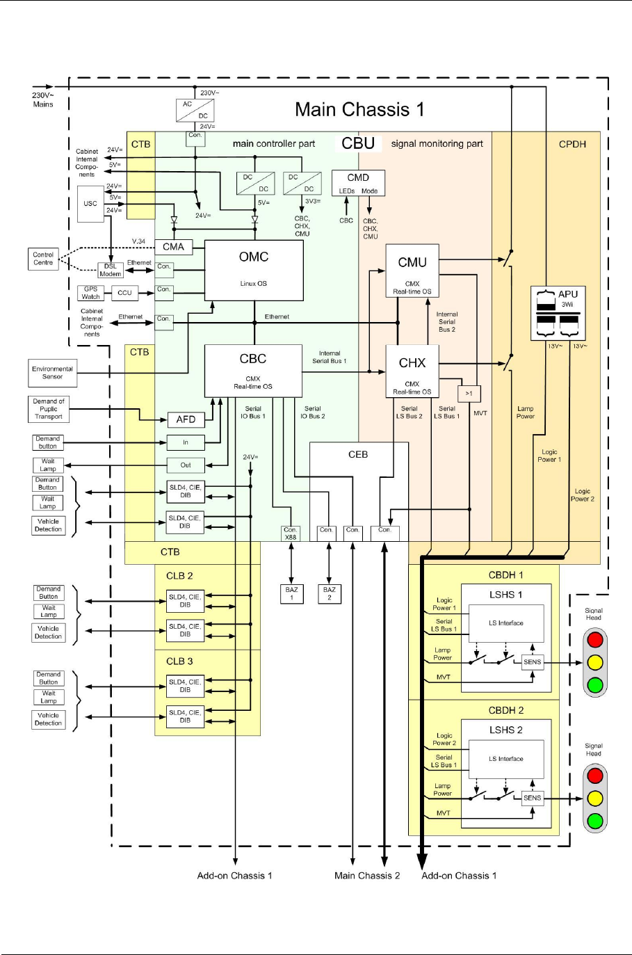
1.9. Schematic representation of main chassis
Fig. 6: Block diagram of main chassis 1
Sitraffic sX
Service manual controller technology 23
Technical concept
Siemens AG V1.0 A001a / 2014-08-20
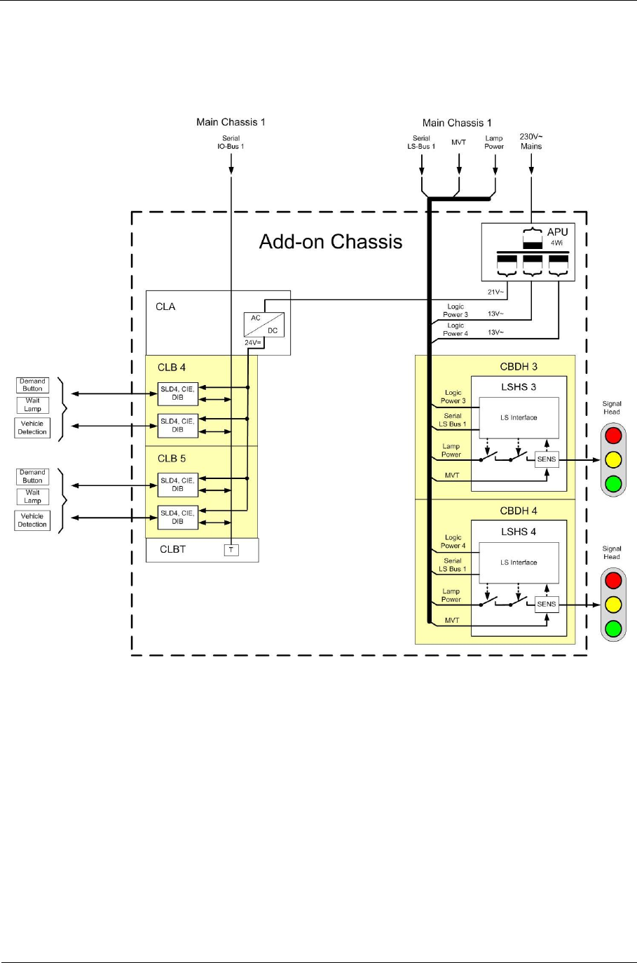
1.10. Schematic representation of add-on chassis
Fig. 7: Block diagram of add-on chassis 1 and 2
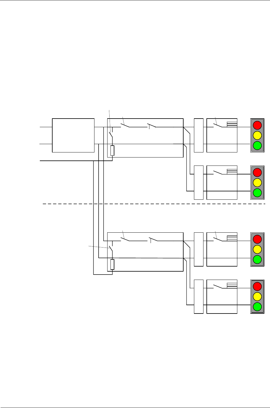
1.11. Switch-off route
There are five switch-off routes in the event of an error in the outdoor
installation:
■Switching off with the triac (1-24) on the LED switch.
■Switching off each individual LED switch via the B relay on the LED
switch.
Sitraffic sX
Service manual controller technology 24
Technical concept
Siemens AG V1.0 A001a / 2014-08-20
■Switching off the 230 -V power supply via the SSR relay on the CPDH
■Switching off the 230 -V power supply via the A relay
on the CPDH (mechanical).
■Emergency switch-off of the entire controller using the fault current
circuit breaker by means of a fault current via the RCD relay of CPDH1
and possibly CPDH2.
A-relay
RCD-relay
LSHS 1
LSHS 4
: : :
B-relay
CPDH 1
SSR-
relay
P1
P2
(N)
PE
A-relay
RCD-relay LSHS 5
LSHS 8
: : :
B-relay
CPDH 2
SSR-
relay
Second
cabinet
C
D
B
H
C
D
B
H
C
D
B
H
C
D
B
H
RCD
in EVU-part
Fig. 8: Switch-off route
Sitraffic sX
Service manual controller technology 25
Technical concept
Siemens AG V1.0 A001a / 2014-08-20
1.12. 230 -V distribution
Here the representation of the 230 -V distribution in the controller. It is
broken down into the utility compartment and the components in the main
chassis
Fig. 9: 230 -V distribution
1.13. Utility compartment
In the 2O/2N cabinet, in the "E compartment" there is place for:
■A service entrance box
■A metering box and
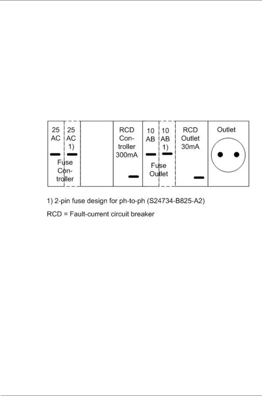
Sitraffic sX
Service manual controller technology 26
Technical concept
Siemens AG V1.0 A001a / 2014-08-20
a power supply utility distribution box with fault current circuit breaker
(300 mA), surge protection, fuse and 30mA fault current circuit breaker for
separately fused service outlet.
The utility compartment parts for sX-H and SH-Hx(max 2760 VA) are
called:
■Utility compartment 230 -V sX-H single-phase S24734-B825-A1
■Utility compartment for sX-H two-phase S24734-
B825-A2
Fig. 10: Utility compartment of sX-H (single-phase/2-phase)
Optionally, extended lightning protection can be installed.
Sitraffic sX
Service manual controller technology 27
Technical concept
Siemens AG V1.0 A001a / 2014-08-20
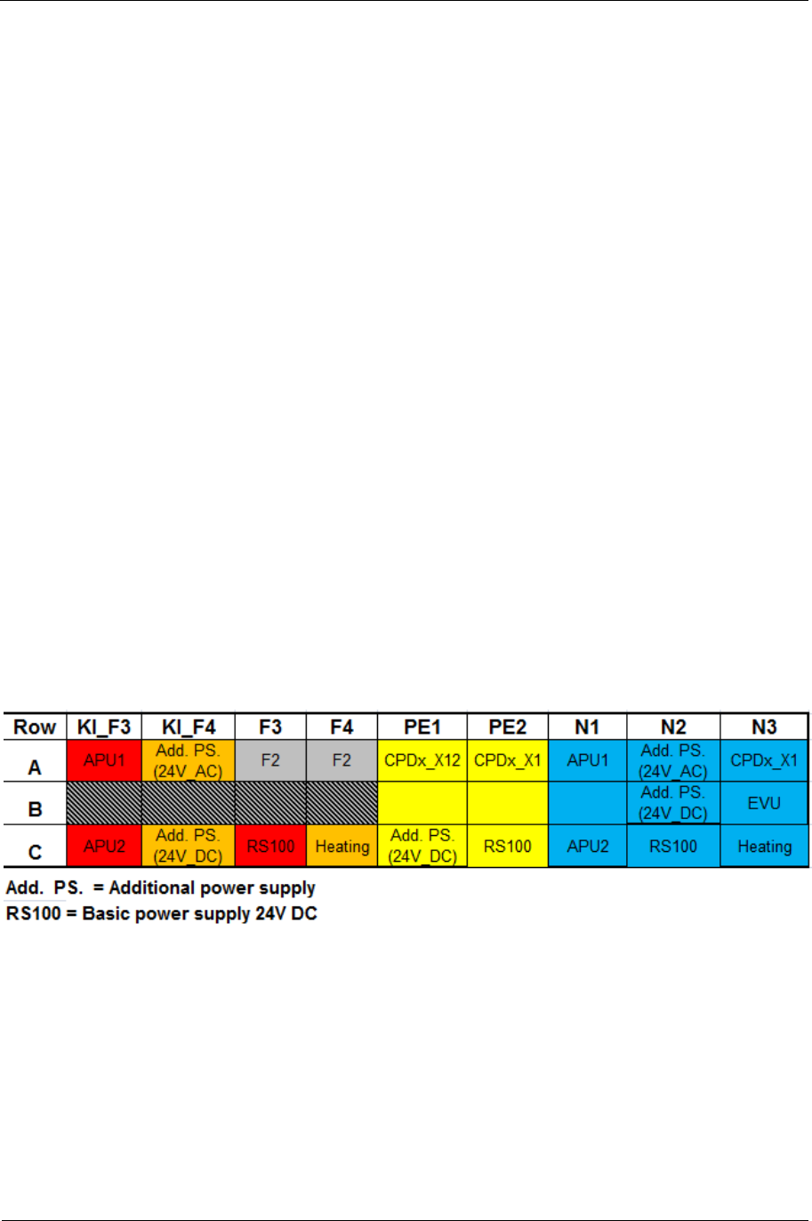
1.14. Power distributor
In the main chassis the power distributor is positioned at the top right.
Here there are 2 automatic circuit breakers with the following function:
■Left: Fuse F1, 16 A C labeled "Contr." for control and power supplies.
■Right: Fuse F2, 16 A B marked "Signals" for the LED signal heads.
For phase-to-phase controllers these fuses can be designed as 2-pin.
(For this another mounting angle is required).
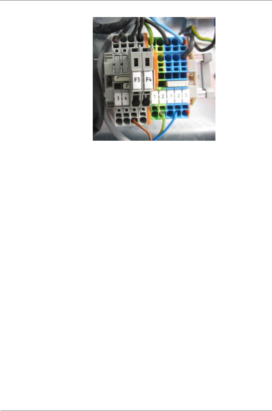
Below this the power distributor terminal block is located. In it there
are the fuses F3 and F4. To replace the fuse, it is to be swung
downward. Then the hatch can be opened and the fuse is accessible. In
it there are 2 microfuses F3 and F4 with 4.0 AT each.
■F3 for power supply, APU1 transformer and APU2 transformer
■F4 for additional power supply, cabinet heater.
The replacement fuse set is as follows:
Set 20x fuse 4AT 250 V L24730-A899-A4
Here is the terminal assignment of the power distributor.
Tab. 3: Power distributor assignment
Sitraffic sX
Service manual controller technology 28
Technical concept
Siemens AG V1.0 A001a / 2014-08-20
Fig. 11: Pattern of power distributor

Sitraffic sX
Service manual controller technology 29
Technical concept
Siemens AG V1.0 A001a / 2014-08-20
1.15. Power consumption of sX-H
Power
con-
sumption
(mA)
Sample
device
5 V 13V 24
VNumber Comment
OMC 700 0 1 Controller
CMA 150 0 0 Modem
CBU 0 260 1 VDE SIMO
CPDH 60 50 1 LED power supply
SLD4 0 60 2 Loop detector
AFD+FEE 500 0 0 PT receiver
CIE/CIO/CED 0 50 0 24V IO boards
DIB-E 0 50 0 Video
CIAC 0 50 0 230V IO boards
GPS 20 0 1 GPS receiver
BAZ2 0 70 1 BAZ
ext. manual
panel
(+24V Man. P.)
0250 0 Ext. command unit
(+24V Man. P.)
24V
(+24V_IO) 200 0 24V
Modem
(+24V_MOD) 0150 1 Modem
CEB (IO-
Extension) 200 0 0 CEB (Optional
interfaces
extension)
LSHS 0 700 0 1 LED switch
I ( mA ) P ( W )
Total 5V 780 3,9
Total 13V 700 9,1
Total 24V 650 15,6
Total 28,6
Tab. 4: Power consumption

Sitraffic sX
Service manual controller technology 30
Components
Siemens AG V1.0 A001a / 2014-08-20
2. Components
2.1. Power connection
■Fuses
■Fault current circuit breaker
■Electrical outlet
■Fuses of main chassis
left F1, controller,
right F2, LED signal head, CPDH
In the power distributor, fold-out fuse retainer (F3 and F4)
F3 (at F1) 24 -V power supply unit, APU
F4 (at F1) add-ons.
2.2. Power supplies
■A switched-mode power supply 230 V /24 V (V24069-Z8043-A1) for
CBU and modules of the IO1 bus that are located in the main chassis.
■APU1 transformer for the supply of the internal logic of the two LED
switch modules in the main chassis via plug connections of the CPDH.
■APU2 transformer for the supply of the two LED switch modules in the
add-on chassis via plug connections of the CPA.
Additionally, supply of the modules of the IO1 bus that are located in
the add-on chassis above the AC/DC transformer on the CLA.
■CPDH supply for the LED signal heads via LED switch
■Additional power supply 24 VDC/48 W for additional devices such as
modems or cameras.
For this additional power supply there is an adapter to be installed in a
CLB installation location.
Sitraffic sX
Service manual controller technology 31
Components
Siemens AG V1.0 A001a / 2014-08-20
■Toroidal transformer for supply to demand buttons and confirmation
devices for 24 -V alternating current.
2.3. CBU
2.3.1. Operating principle of the CBU
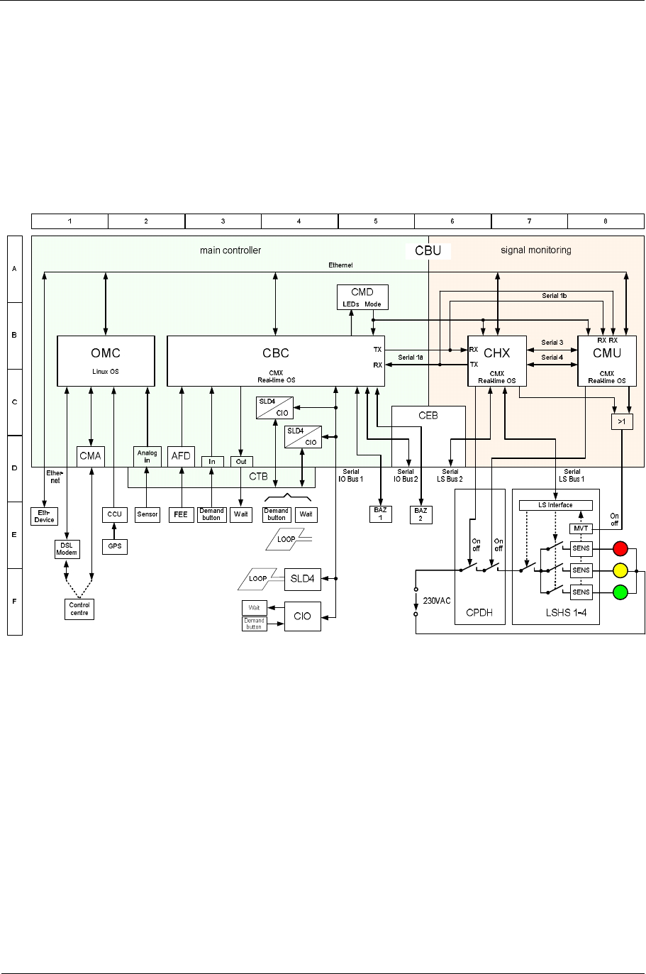
Fig. 12: Block diagram of the CBU
For the CBU (S24734-A870-A10) a control unit and a signal monitoring
unit of an intersection controller are built in onto one module. In the
figure, the area of the control unit is marked green (at the left) and that of
the signal monitoring unit red (at the right). Assemblies and modules that
are to be plugged into the CBU are highlighted white.
The control unit processes the signal plan and depending on the traffic
situation that is identified by the detectors generates switch requests for
the LED signal heads.

Sitraffic sX
Service manual controller technology 32
Components
Siemens AG V1.0 A001a / 2014-08-20
The signal monitoring unit sets the LED signal heads in accordance with
the switch requests if—after having checked them—it has been
determined that no hazardous conditions result in the intersection.
The signal monitor can operate 230-V LED modules with the LED switches
of type LSHS.
If the signal monitor identifies that the outdoor system is functioning with
faults, it can switch off its operating power supply in order to prevent
hazardous signal monitoring conditions. Switching off takes place with a
relay on the CPDH. Both processor modules of the signal monitor can
switch off the operating power supply independent of each other.
Name Description Position
in the
block
diagram
AFD Module for evaluating request signals from PT D3
BAZ 1 First command unit E5
BAZ 2 Second command unit E6
CBC Processor module with real-time processing
system for the processing of time-critical
interfaces of the OMC
B4
CCU
(CCUE) GPS-controlled clock E2
CEB Expansion module necessary for second BAZ,
second I/O bus and second LED switch bus C6
CHX Signal monitoring processor 1 for the activation
and monitoring of the signal sensors. B7
CIO I/O module with 8 inputs and 8 outputs. In the
CBU only the 8 inputs can be used. C4, F4
CMA V.34 modem for control center connections (PPP) D1
CMD Module for setting the operating mode of CBC,
CHX and CMU B1
CMU Signal monitoring processor 2 for monitoring the
functioning of signal monitoring processor 1. B8
Control
center Traffic control computer (control center) F1
CPDH Energy distribution unit for up to four LSHSs. F6
CTB Backplane with spring terminals for connecting
the interfaces D3

Sitraffic sX
Service manual controller technology 33
Components
Siemens AG V1.0 A001a / 2014-08-20
Name Description Position
in the
block
diagram
Demand
button Demand button (8-piece connectable) E3, E4,
F3
DSL
Modem Digital modem for control center connections
(TCP/IP) E1
Eth.
device Local device with Ethernet connection (e.g.
detector) E1
FEE Radio receiver for request signals from PT E2
GPS GPS receiver with antenna E2
In 8 parallel inputs can be used for demand buttons. D3
LOOP Loop E4, F4
LSHS 230 -V LED switch F8
MVT Changeover switch for the sensors for test mode
of CHX and CMU, can be activated independently
of one another.
E8
OMC Control module for Linux operating system B1
OUT 8 parallel outputs can be used for confirmation
devices. D3
SENS Sensors for LED voltage and LED current F8
Sensor Environment sensor, 2 inputs are provided (e.g.
for temperature and humidity) E2
SLD4 Loop detector for 4 loops C4, D4,
F4
Wait Confirmation lamp (8-piece connectable) E4, F4
Tab. 5: Explanations for block diagram of the CBU (see Fig. 12)

Sitraffic sX
Service manual controller technology 34
Components
Siemens AG V1.0 A001a / 2014-08-20
2.3.2. Control unit
The processor module OMC and the processor module CBC form the
control unit of the intersection device.
2.3.2.1. OMC processor module
The processor of the OMC has a Linux operating system and assumes the
following tasks:
■Evaluation of detectors and demand buttons
■Traffic-actuated signal plan processing
■Submission of the signal pattern to the CBC via the network connection
■Evaluation of the GPS time
■Communication with the control center via Ethernet (TCP/IP)
■Communication with the control center via RS232 (PPP)
■Support of remote maintenance of CBC, CHX and CMU from the control
center
■Detection by a maximum of two environment sensors
■Switching off the UPS after a power failure message to the control
center
Additionally, the OMC delivers battery power to the real-time clock on the
CBU.
2.3.2.2. CBC processor module
The processor of the CBC has a CMX real-time operating system and
processes the following tasks:
■Acquisition of the detector information (SLD4, DIB-E) via the busses
IO1 and IO2
■Detection of the parallel inputs on the CBU

Sitraffic sX
Service manual controller technology 35
Components
Siemens AG V1.0 A001a / 2014-08-20
■Setting the parallel outputs on the CBU
■Detection of the parallel inputs of the IO modules (e.g. CIE, CIO, CIAC)
via the busses IO1 and IO2
■Setting the parallel outputs of the IO modules (e.g. CIE, CIO, CIAC) via
the busses IO1 and IO2
■Measuring of assignment times and assignment pauses for the
detectors and parallel inputs.
■Controlling the two BAZ interfaces
■Evaluating the requirements of PT that are received from the AFD
interface via radio.
■Communication with the OMC processor module via Ethernet
■Fail-safe function, if the OMC is not ready for use because of failure or
update of the firmware.
2.3.3. Signal monitoring unit
The signal monitoring unit is redundantly structured for the two processor
modules CHX and CMU.
2.3.3.1. CHX processor module
The processor of the CHX has a CMX real-time operating system and
processes the following tasks:
■Receipt of a new signal pattern from the CBC via the Serial 1a
connection.
■Examination based on the signal monitoring configuration for whether
the specifications of the control unit do not pose a risk to safety.
■Setting the LED signal heads in the signal heads according to the
specification of the control unit. For this purpose, transmission of
control commands to the LED switches LSHS via the LS bus.

Sitraffic sX
Service manual controller technology 36
Components
Siemens AG V1.0 A001a / 2014-08-20
■Obtaining sensor information concerning the operating statuses of the
LED signal heads via the LS bus.
■Transmission of sensor information via the Serial 3 connection to the
CMU module for parallel examination.
■Examination of whether the outdoor system is functioning without
faults (LED module failure, fault currents, short circuits)
■In the presence of hazardous conditions, switch off the outdoor system
via triac of the LED lamp switch or via relay of the CPDH.
■Briefly generating faults that the CMU processor must identify by
activating the "monitor validation test" (MVT). If this is not the case,
switch off outdoor system via relay of the CPDH.
2.3.3.2. CMU processor module
The processor of the CMU has a CMX real-time operating system and
processes the following tasks:
■Parallel receipt of a new signal pattern from the CBC for the CHX via
the Serial 1b connection.
■Examination based on the signal monitoring configuration for whether
the specifications of the control unit do not pose a risk to safety.
■Examining sensor information that was received by the CHX module
via the Serial 3 connection for whether it matches the specifications of
the control unit.
■Examining whether the outdoor system functions free of faults (LED
module failure, fault currents, short circuits) on the basis the sensor
information in parallel with the CHX
■In the presence of hazardous conditions, switch off the outdoor system
via relay of the CPDH.
■Briefly generating faults that the CHX processor must identify by
activating the "monitor validation test" (MVT). If this is not the case,
switch off outdoor system via relay of the CPDH.

Sitraffic sX
Service manual controller technology 37
Components
Siemens AG V1.0 A001a / 2014-08-20
Safety:
The two processors CHX and CMU constantly check each other for proper
functioning.
Via the relay of the CPDH they can switch off the operating power supply
for the signal heads independently of each other.
The "monitor validation test" (MVT) can be activated by each processor
module independently of the other. For this, both processors produce
cyclically artificial brief faults in order to test the other processor. The
outdoor system is switched off if the processor to be tested does not
identify a fault. If a processor notices that these faults do not occur
anymore, it switches off the outdoor system here too.
Sitraffic sX
Service manual controller technology 38
Components
Siemens AG V1.0 A001a / 2014-08-20
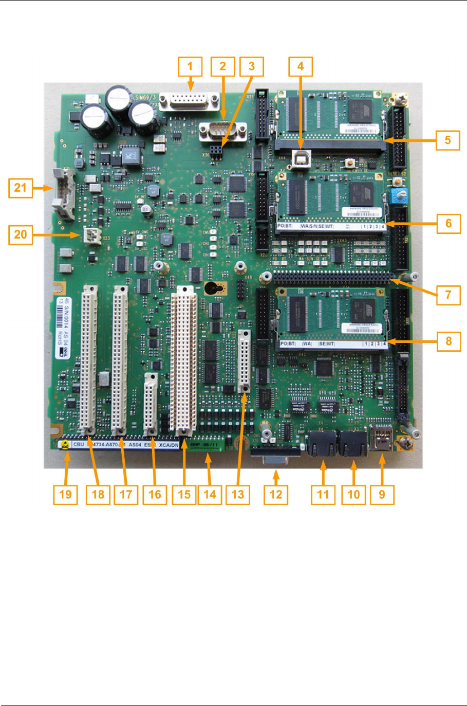
2.3.4. Plug connector and interfaces of the CBU
Fig. 13: Plug connector of the CBU

Sitraffic sX
Service manual controller technology 39
Components
Siemens AG V1.0 A001a / 2014-08-20
No. Ref. Plug
Name Description
1X33 BAZ1 Connection for first BAZ controller
2X35 CMA data RS232 connection for CMA modem module
3X36 CMA-SV Power supply connection for CMA modem
module
4X2 USB device USB device plug
5X44 CMU Slot for processor module CMU (SIMO)
6X43 CHX Slot for processor module CHX (SIMO)
7X34 CEB Slot for interface expansion CEB
for second controller BAZ2, second IO bus and
second LS bus.
8X42 CBC Slot for processor module CBC (controls)
9X9 Micro SD
Card MicroSD card holder
10 X7 Ethernet
Internal Ethernet for device-internal accessories
(e.g. detectors)
11 X4 Ethernet
Central
device
Control center connection (e.g. DSL modem)
12 X16 Debug_SI
MO Service PC connection for CHX
Troubleshooting for SIMO through service PC
13 X22 AFD Slot for AFD
Evaluation module for request telegrams from
PT
14 X30 CTB2 Second plug connection for CTB
15 X41 OMC Control module OMC
16 X47 CMD Module for operating the CBU
17 X40 Serial IO 2 Plug 2 for an I/O expansion card
(SLD4, CIO)
18 X39 Serial IO 1 Plug 1 for an I/O expansion card
(SLD4, CIO)
19 X29 CTB1 First plug connection for CTB
20 X23 SV-In 24V power supply connection of the CBU
21 X31 CCU Drop cable connection for GPS clock CCU
Tab. 6: Description of the plug connector of the CBU, see Fig. 13
Sitraffic sX
Service manual controller technology 40
Components
Siemens AG V1.0 A001a / 2014-08-20
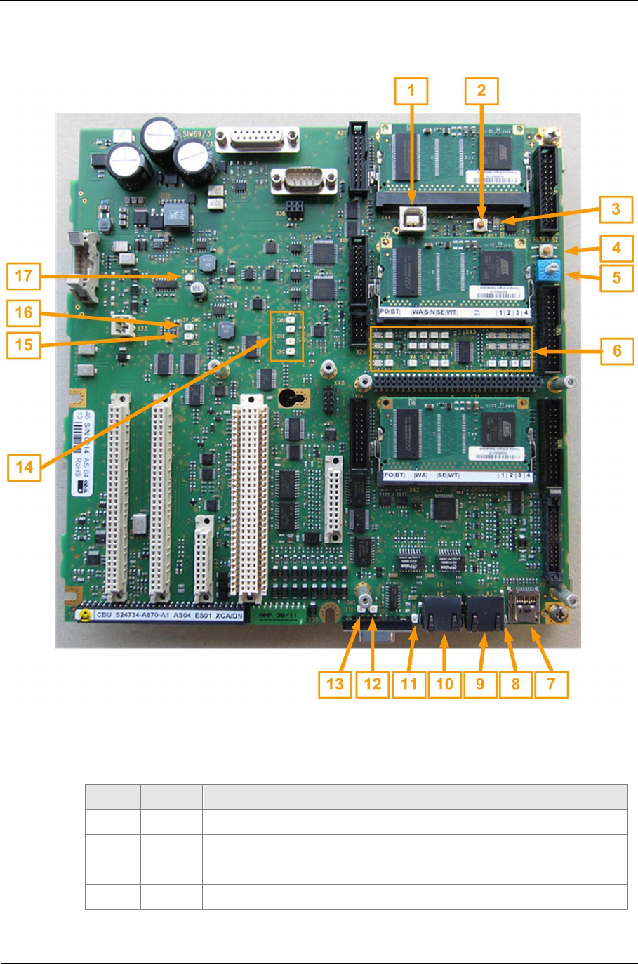
2.3.5. Display and control elements of the CBU
Fig. 14: Display and control elements of the CBU
No. Ref. Description
1X2 USB device plug
2S3 Eject button for MicroSD card holders
3H25 Eject LED for MicroSD card holders
4S2 Reset button of the CBU
Sitraffic sX
Service manual controller technology 41
Components
Siemens AG V1.0 A001a / 2014-08-20
No. Ref. Description
5S1 Mode selector switch for CBU (CBC, CHX and CMU
Must be in position "0" if a CMD is plugged in.
6-- LED array for CBC, CHX and CMU (see Fig. 15)
7X9 MicroSD card holder
8H16 Power indicator for device-internal LAN
9X7 Ethernet for device-internal accessories
(e.g. detectors)
10 X4 Control center connection (e.g. DSL modem)
11 H6 Link/activity LED for Ethernet for control center connection
12 H3 Link/activity LED: CBC à OMC
13 H8 Link/activity LED: OMC à CBC
14 H14
H10
H12
H2
Link/activity LEDs for CBU-internal LAN connections
CMU à CHX
CHX à CMU
CHX à CBC
CBC à CHX
15 H48 LED "USV_OK"
5V operating voltage of USC for OMC is okay
16 H1 LED "CBU_5V_OK"
5V operating voltage of CBU for OMC is okay
17 H47 LED "CPD_Relay_Driver_OK"
5V operating voltage for components of the CBU is okay
Tab. 7: Description of the display and control elements of the CBU (see Fig. 14)
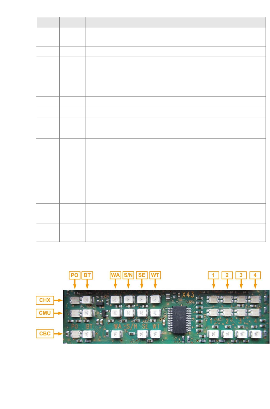
Fig. 15: LED array of the CBU

Sitraffic sX
Service manual controller technology 42
Components
Siemens AG V1.0 A001a / 2014-08-20
LED CHX CMU CBC
PO Power Power Power
BT Boot Boot Boot
-- -- -- --
WA Watchdog alarm Watchdog alarm Watchdog alarm
S/N New signal pattern New 100ms Slot --
SE System error System error System error
WT Watchdog Trigger Watchdog Trigger Watchdog
Trigger
-- -- -- --
1Primary Alarm PI1 Secondary Alarm PI1 TBD
2Primary Alarm PI2 Secondary Alarm PI2 TBD
3Primary Alarm PI3 Secondary Alarm PI3 TBD
4Primary Alarm PI4 Secondary Alarm PI4 TBD
Tab. 8: Identification of the LEDs of the processors CBC, CHX and CMU
LED LED function LED
Status Meaning
PO Power Green
Red
off
Operating voltage is okay
Operating voltage is too low
Operating voltage is off
BT Boot Red Firmware is booting
-- -- -- --
WA Watchdog alarm Red Watchdog fault
S/N
of
CHX
New signal pattern Flashes
green A new signal pattern was
detected by the LED switches.
S/N
of
CMU
New 100ms Slot Flashes
green A new signal pattern is
transmitted from the controls
(CBC) to the signal monitoring
(CHX, CMU).
SE System error Red The firmware has identified a
malfunction (hardware-internal
or firmware-internal).
WT Watchdog Trigger Flashes
green Watchdog is triggered
-- -- -- --

Sitraffic sX
Service manual controller technology 43
Components
Siemens AG V1.0 A001a / 2014-08-20
LED LED function LED
Status Meaning
1-4 Primary alarm
partial intersection
1-4
Controlled by CHX software
see Tab. 10
1-4 Secondary alarm
partial intersection
1-4 Off
yellow
Controlled by CMU software
see Tab. 11
1-4 TBD -- Controlled by CBC software
Tab. 9: Meaning of the LEDs of the processors CBC, CHX and CMU
Primary Alarm LEDs
PI 1-4 Partial intersection characteristics
Color Status Status / outdoor system SIMO
Off Off Not present --------
Green On Active, OMC controls the signal
pattern Live
Green 1Hz Active, fail-safe mode, CBC
controls the signal pattern Live
Red+gree
nOn OMC switches on or OFF (on/off
pattern proceeds) Not live
Red+gree
n1Hz Off, free of faults (off-flashing,
off, etc.) Not live
Red+gree
n2Hz OFF with network fault (fault
flashing) Not live
Red On switches off ("all yellow" pattern
proceeds) Not live
Red 1Hz Faulty (fault flashing) Not live
Red 2Hz Faulty, system fault (off) Not live
Tab. 10: Meaning of the LEDs for primary alarm
Secondary Alarm
LEDs PI 1-4 Partial intersection characteristics
Color Status Status / outdoor system SIMO
off Off No secondary alarm No effect
Red+green On Secondary Alarm No effect
Tab. 11: Meaning of the LEDs for secondary alarm
Sitraffic sX
Service manual controller technology 44
Components
Siemens AG V1.0 A001a / 2014-08-20
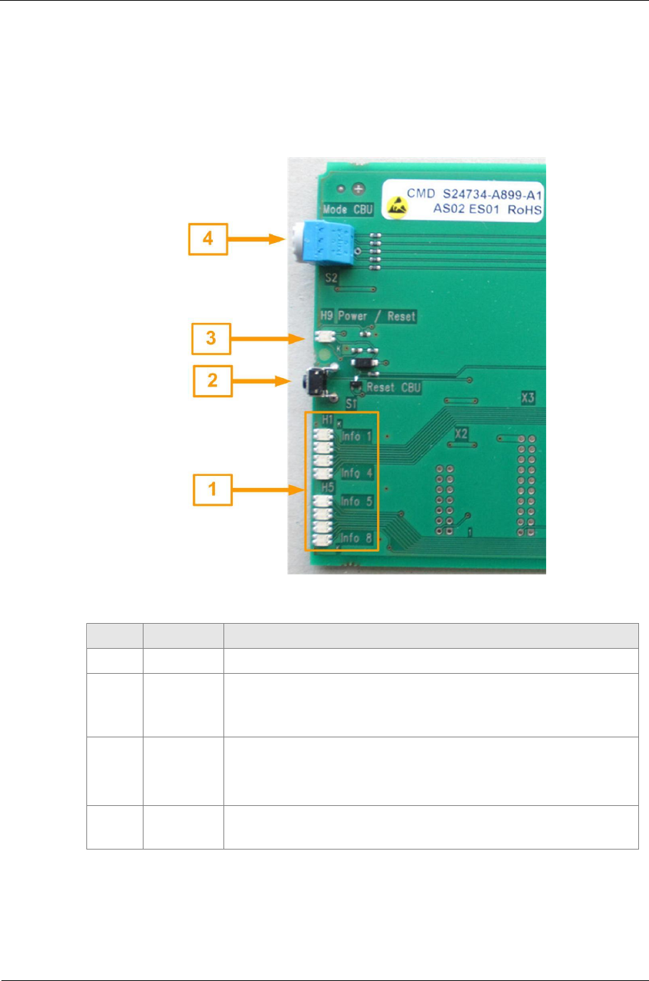
2.4. CMD
The operating mode of the three processors on the CBU is selected with the
CMD (S24734-A899-A1).
Furthermore, the three processors on the CBU can be reset.
Fig. 16: Display and control elements of the CMD
No. Ref. Description
1H1 - H8 LEDs controlled by the CBC
2S1 Reset button for CBU (CBC, CHX and CMU)
Works in parallel to the reset button S2 of the CBU.
The OMC does not receive a reset signal.
3H9 Power and reset LED
■Green Operating power supply is present
■Green + red Reset button is pressed
4S2 Mode selector switch for CBU (CBC, CHX and CMU).
Rotary switch S1 of the CBU must be in position "0"
Tab. 12: Meaning and function of the display and control elements of the CBU
Sitraffic sX
Service manual controller technology 45
Components
Siemens AG V1.0 A001a / 2014-08-20
2.4.1. Reset of the CBU
The CBU attains a hardware reset if the reset button of the CMD is pressed
(see Fig. 16, detail no. 2).
The reset affects the process modules CBC, CHX and CMU.
The OMC is not reset due to this.
If the button S2 is present on the CBU, it works in parallel with the reset
button on the CMD. The CBU can be reset with both buttons.
2.4.2. Setting the operating mode of the CBU
The operating mode for the processor modules CBC, CHX und CMU is
selected with the rotary switch of the CMD (see Fig. 16, detail no. 4). The
operating mode of the OMC is not affected by this.
Selection of the operating mode of the CBU
The signals of the rotary switch of the CBU and of the CMD are connected in
parallel.
If the operating mode should be set with the rotary switch of the CMD, the
rotary switch of the CBU must be set to the "0" position and vice versa.
Selector
switch
position
Function
0Normal operation (without lamp switches)
1 Simulation mode
2 Operation without outdoor system (only LSHS LED display)
3Reserved for lamp assignment test
4Signal monitor test
5Load configuration
6Firmware update mode
7Relay ON, lamp power supply on for test purposes
8Update mode for LSHS

Sitraffic sX
Service manual controller technology 46
Components
Siemens AG V1.0 A001a / 2014-08-20
Selector
switch
position
Function
9Update mode for CPDH
AReserved
B Reserved
C Reserved
D Reserved
E Reserved
F Reserved Tab. 13 Rotary switch functions
2.4.3. Display of operating statuses of the CBC
The firmware of the CBC operating statuses can display via 8 LEDS on the
front of the CMD (see Fig. 16, detail no. 1). The LEDs are two-colored
(red/green).
2.5. CTB
The terminal blocks of the CBU are transferred to the CTB (S24734-A871-
A1). The CTB is connected to the CBU with the plug connections. This way
the wiring does not have to be reconnected when replacing the CBU.
2.5.1. Assignment of CTB_X5
The IN and OUT signals of the CBU are applied on terminal block X5. The
+24 V for the OUTs must be supplied by the additional power supply. :
■8 external +24 -V parallel inputs of the CBU (X5, IN1 to IN8) can be
used for connecting demand buttons (for plug connector X5 see Tab.
14: Assignment of the X5 terminal block of the CTB).
■8 external +24 -V parallel outputs of the CBU (X5, Out1 to Out8) can be
used for connecting confirmation devices (for plug connector see Tab.
14: Assignment of the X5 terminal block of the CTB).
■Power supply feed for OUT1 - OUT8 (+24V_PED_IN)

Sitraffic sX
Service manual controller technology 47
Components
Siemens AG V1.0 A001a / 2014-08-20
X5
Row/
Contact c a Function
1IN1 IN1 Inputs for
+24-V signals
(demands buttons)
0V active
2IN2 IN2
3 IN3 IN3
4 IN4 IN4
5 IN5 IN5
6 IN6 IN6
7 IN7 IN7
8 IN8 IN8
9Out 1 Out 1 Outputs for
+24-V signals
(confirmation devices)
High Side Switch
24V active
10 Out 2 Out 2
11 Out 3 Out 3
12 Out 4 Out 4
13 Out 5 Out 5
14 Out 6 Out 6
15 Out 7 Out 7
16 Out 8 Out 8
17 +24V_PED_IN +24V_PED_IN Power supply for high side
switch (OUT1-OUT8)
Tab. 14: Assignment of the X5 terminal block of the CTB
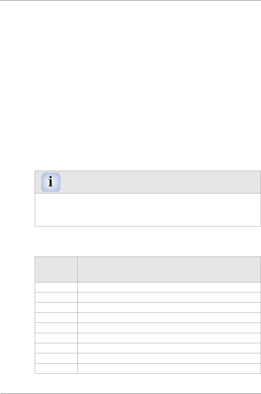
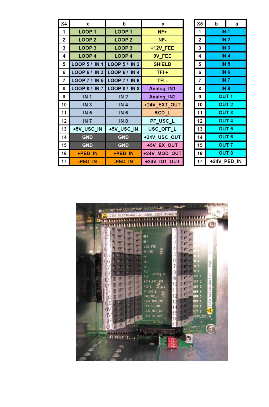
2.5.2. Assignment of CTB_X4
Operating power supplies and the connections of the CBU installation
locations CBU_X39, CBU_X40 and CBU_X22 (AFD) are present at X4. The
following signals can be connected:
■UPS for OMC and CMA
■24 -V output for ext. modem
■External command unit BAZ2 (only 24V output and emergency-off
signal)
■Receiver for PT request

Sitraffic sX
Service manual controller technology 48
Components
Siemens AG V1.0 A001a / 2014-08-20
■2 analog inputs (X4, AL1 and AL2)
■2 x 8 terminals for SLD4 detectors (max. 2) for connecting 4 loops each
(X4 LOOP1 to LOOP8).
or
2 x 8 terminals for CIE modules (max. 2) for connecting 8 parallel
inputs each (X4 IN1 to IN8 and IN1' to IN8').
■24 V operating power supply for the parallel IO of the CIE modules
(+PED_IN, -PED_IN-).
X4
Row/
Contact c b a
1LOOP1A LOOP1B NF+
2LOOP2A LOOP2B NF-
3LOOP3A LOOP3B +12V_FFE
4LOOP4A LOOP4B 0V_FFE
5LOOP5A / IN1 LOOP5B / IN2 PE (shield)
6 LOOP6A / IN3 LOOP6B / IN4 TFI+
7LOOP7A / IN5 LOOP7B / IN6 TFI-
8LOOP8A / IN7 LOOP8B / IN8 Analog IN1
9IN1 IN2 Analog IN2
10 IN3 IN4 +24V_EXT_OUT
11 IN5 IN6 RCD-L
12 IN7 IN8 PF_USC_L
13 +5V_USC_IN +5V_USC_IN USC_OFF_L
14 GND GND +24V_USC_OUT
15 GND GND +5V_EX_OUT
16 +PED_IN +PED_IN +24V_MOD_OU
T
17 -PED_IN -PED_IN +24V_IO1_OUT
Tab. 15: Assignment of the terminal block X4 of the CTB
Optionally, the installation locations X39 (LOOP1-4) and X40 (Loop5-8) of
the CBU can be equipped with loop detectors SLD4 or IO modules CIE.
In the case of mixed equipment, installation location X39 is intended for
the SLD4 and installation location X40 for the CIE because there are 2
contact points for the signals here. This way the induction loops can be

Sitraffic sX
Service manual controller technology 49
Components
Siemens AG V1.0 A001a / 2014-08-20
connected for the terminals 1 to 4. Two terminals per input are available
for the demand buttons in this case. Contacts 5 to 8 for the first buttons
and contacts 9 to 12 for the second buttons.
Name Volt-
age
/V
Max.
contin
uous
current
/A
Terminal
CTB
X4
Use
for
24V_EXT +24 0,15 A10 External command
unit
24V_USC_OUT +24 0,50 A14 Charging current USC
+5V_EX_OUT +5V 0,30 A15 Add-ons
24V_MOD_OUT +24 0,25 A16 Modem
24V_IO1_OUT +24 0,60 A17 Add-ons
IO1 bus (1)
Tab. 16: Load capacity of the power supply outputs of the CTB
(1) The power supply "24V_IO1" can have a maximum of 0.6A applied to it.
It is to be noted that "24V_IO1" also supplies power to all the modules of
the IO1 bus that are built in to the main chassis. This includes the two
installation locations X39 and X40 on the CBU and the installation locations
on the CLB modules that are plugged in directly below the CTB.
For power consumption of the modules see
Tab. 4.The sum of the current for all the modules of the IO1 bus in the
main chassis and the current taken from terminal 24V_IO1_OUT may not
exceed 0.6A.
Since the signals on the CLB terminals cannot be sufficiently labeled, the
terminal assignment plan is attached to the chassis. See indicator plate Fig.
17.
Sitraffic sX
Service manual controller technology 50
Components
Siemens AG V1.0 A001a / 2014-08-20
Fig. 17: Indicator plate for CTB module
Fig. 18: View of CTB module
Sitraffic sX
Service manual controller technology 51
Components
Siemens AG V1.0 A001a / 2014-08-20
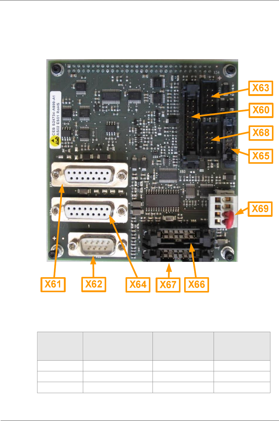
2.6. CEB
The CEB (S24734-A875-A1) is an interface expansion card that can
optionally be plugged into the CBU.
Fig. 19: CEB view
Connector Function Level Software for
interface
present
X60 I/O2 Bus CMOS, serial yes
X61 2. BAZ (external) RS485 yes
X62 9 pin D-Sub RS232

Sitraffic sX
Service manual controller technology 52
Components
Siemens AG V1.0 A001a / 2014-08-20
Connector Function Level Software for
interface
present
X63 SPI CMOS
X64 3. BAZ RS485 yes
X65 LS2 bus (LSxS5-8) RS422 yes
X66 UART TTL
X67 UART TTL
X68 SPI CMOS
X69 24V power supply 24V
Tab. 17: CEB connector
2.7. OMC-U
Tasks:
■Controls the procedure of the signal plans.
■Buffer battery for real-time clock and SRAM of the OMC and the CBU.
■Dongle
■Control center connection via Ethernet or RS 232
■Operating mode switch
■LEDs (for display of operating mode)
■Service PC connection
■USB connection for power supply
The part number/replacement part of the OMC is: S24777-A3534-A20.
The dongles are not labeled. The enabled functions could be displayed
with the WEB GUI. In addition, with Canto P the required certificate is
stored there.
For an order the required functions must be indicated.
See Manual 1g section 3.3.1
Sitraffic sX
Service manual controller technology 53
Components
Siemens AG V1.0 A001a / 2014-08-20
The following CF cards are available:
Part number Description
A8D00000174 CF Card 1GB (Standard)
Tab. 18: CF card part numbers
Warning
The Dongle and the CF card must be ordered separately
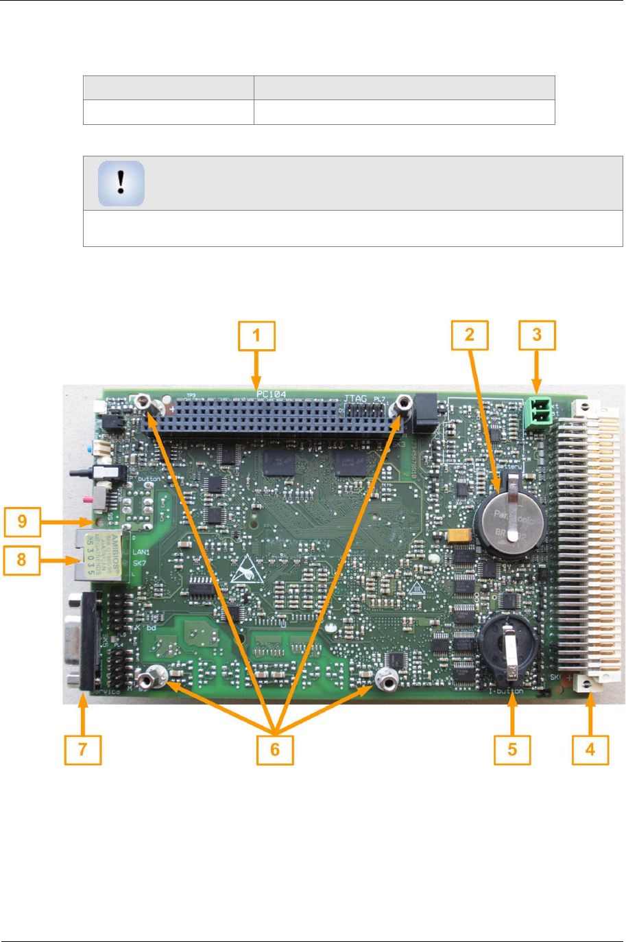
Fig. 20: OMC-U top side
Sitraffic sX
Service manual controller technology 54
Components
Siemens AG V1.0 A001a / 2014-08-20
No. Ref. Description
1SK4 Multipole socket connector for connecting a PC104 module
2B1 Battery in its retainer (plus pole up)
3PL6 Connection for alternative battery
4SK8 Basic multipole connector
5SK6 Retainer for dongle (broad side of the dongle facing up, see
Fig. 25)
6Bolt for fastening a PC104 module
7SK5 Connection for service PC
8SK7 LAN RJ45 10/100MBit with diagnostics LEDs
9-- Module slot
Tab. 19: Description of OMC-U top side (see Fig. 20)
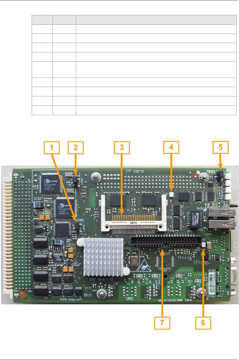
Fig. 21: OMC-U bottom side
Sitraffic sX
Service manual controller technology 55
Components
Siemens AG V1.0 A001a / 2014-08-20
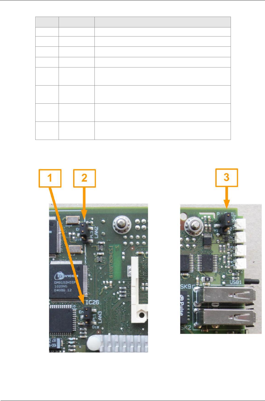
No. Ref. Description
1PL1 Jumper for switching on of LAN 3 for the CBU
2PL2 Jumper for switching on of LAN 2 for the CBU
3SK10 Slot for compact flash
4LP3 Operation LED for compact flash
5PL3 Jumper for selecting the logic of the power-fail signal
6LP1 Operation LED for IDE interface
7SK1 Slot of the IDE interface for flash cards / HD
Tab. 20: Description of OMC-U bottom side (see Fig. 21)
Usually a battery, "Panasonic BR2032", is built in (-30°C to 80°C)
Battery replacement
The battery is to be changed every 5 years.
Only a "Panasonic BR203" is to be used as a replacement.
The replaced battery is to be disposed of properly.
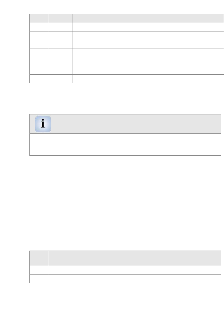
The plug "PL6" is used for connecting an external battery. The external
battery is used for increasing the battery capacity (battery on "B1" + "PL6").
It furthermore serves to maintain the specified temperature range for -40°C
requirements.
When using the modules in the temperature range of -40°C to+80°C, an
external battery, e.g. TADIRAN Model TL-5242/W (-55°C to 85°C), must be
used. The battery built in to the OMC (Panasonic BR2032) is only for -30°C
to 80°C.
Pin
no. Signal name
1+3.6 V
20V Tab. 21: Pinout OMC_PL6
Sitraffic sX
Service manual controller technology 56
Components
Siemens AG V1.0 A001a / 2014-08-20
Ext. battery
Fig. 22: PL6 assignment
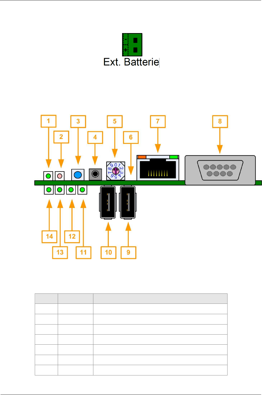
Fig. 23: OMC-U front side
No. Ref. Description
1LP8 Status LED for logic voltage 5VDC
2LP7 Status LED for reset
3S7 Reset button
4S6 Button, used by software
5S5 Operating mode switch
6-- Module slot
7SK7 LAN RJ45 10/100MBit with diagnostics LEDs
Sitraffic sX
Service manual controller technology 57
Components
Siemens AG V1.0 A001a / 2014-08-20
No. Ref. Description
Data (orange) and link (green)
8SK5 RS232 Interface for service ( COM1 )
9SK2 USB host plug 2
10 SK9 USB host plug 1
11 L1 / LP6 Diagnostics for LED L4, controlled by
software
12 L2 / LP5 Diagnostics for LED L3, controlled by
software
13 L3 / LP4 Diagnostics for LED L2, controlled by
software
14 L4 / LP2 Diagnostics for LED L1, controlled by
software
Tab. 22: Description of OMC-U front side (see Fig. 23)
Fig. 24: Position of the jumpers on the OMC
Sitraffic sX
Service manual controller technology 58
Components
Siemens AG V1.0 A001a / 2014-08-20
No. Ref. Position Description
1PL1 1-2, En LAN 3 to components of the CBU is activated
2PL2 1-2, En LAN 2 to the control center via CBU X4 is
activated
3PL3 1-2, Lo Power-fail signal is low active
Tab. 23: Jumper setting for OMC
The jumpers must be in the position shown in Fig. 24.
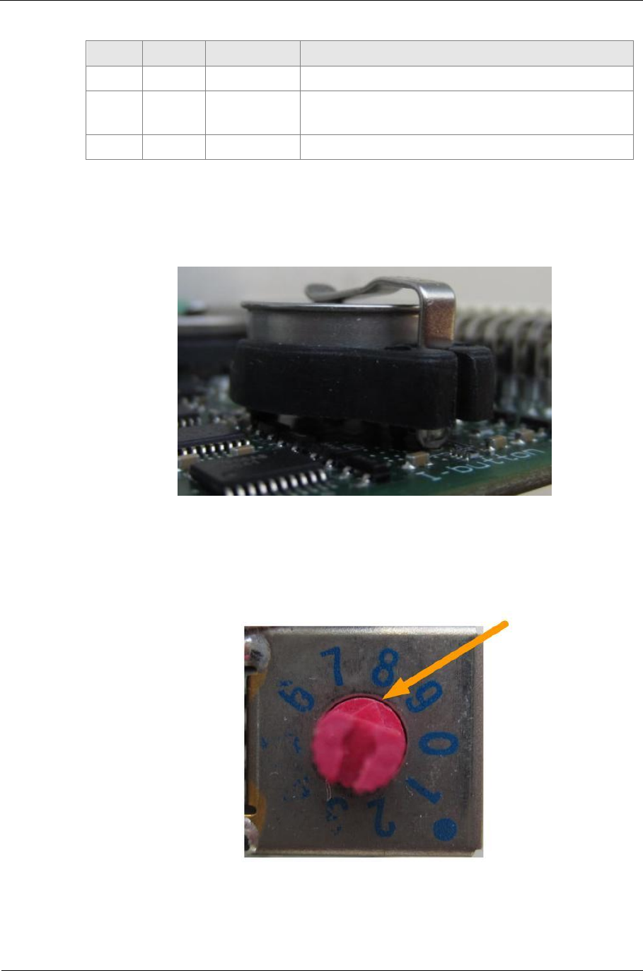
Fig. 25: Placing the dongle in the retainer of the OMC
The dongle is to be placed in such a way that the broad circumferential
edge faces upward (see Fig. 25).
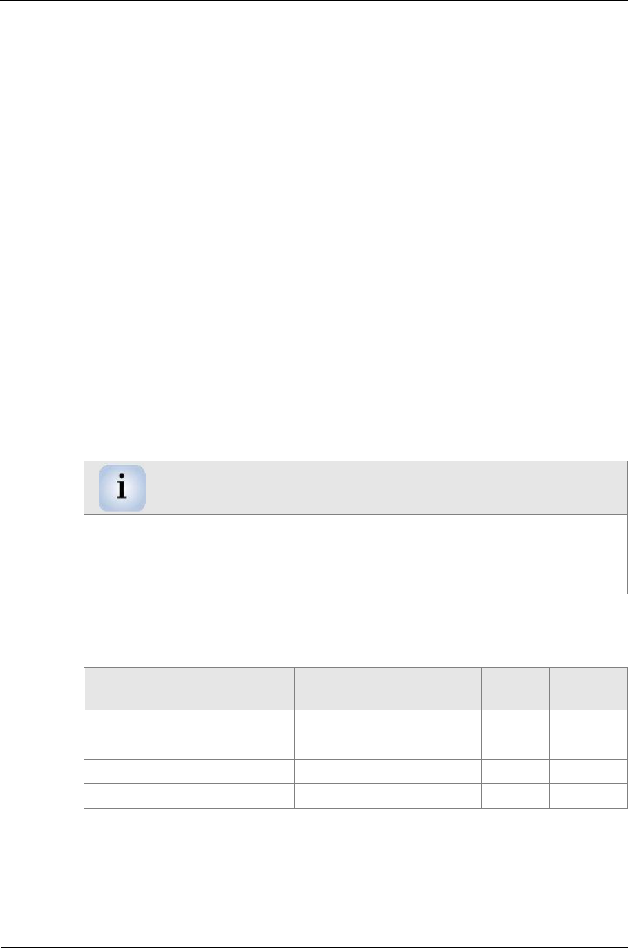
Fig. 26: Identification of the rotary switch position of the OMC
Sitraffic sX
Service manual controller technology 59
Components
Siemens AG V1.0 A001a / 2014-08-20
The flattened side of the rotary switch marks the number of the selected
operating mode. In Fig. 26 operating mode 8 is selected.
The rotary switch functions of the OMC are described in Manual 1g
2.8. CPDH
For sX- H controller the CPDH (S24734-A884-A1) provides the 230 VAC for
the LSHS together with the associated monitors.
The CPDH has A relays, SSR relays with which the feed of the LED power
supply for the LSHSs of the processors of the signal monitoring system can
be switched independently of each other.
The CPDH is at the top right of the chassis. The first LED switch
Backplane(CDBH) is attached from below. The second CDBH is to be
attached to the first. For adding on a third and fourth CDBH there are
appropriate connectors available on the CPDH. All the control signals come
from the control module CBU via a ribbon connector from the left side. The
CPDH should be slid upward for repairs. For this, only the left lower screw
is to be undone.
Note
So that no components are damaged, the module is not to be touched at the
components. Removal is to be performed with a small screwdriver between
CPDH and CDBH in the X9-X14 area. To insert it, only the top edge of the
circuit board is to be pressed
The following is needed for installation.
Material Part number 1. MC 2nd
MC
CPDH module S24734-A884-A1 1 1
CPDH accessories /C10 L24730-E821-A100 1 0
CPDH-X accessories /C10 L24730-E821-A110 0 1
Transformer set 25 VA /C10 L24730-E810-A41 1 1
Tab. 24: CPDH configuration
1. MC means 1st main chassis
2. MC means 2nd main chassis
Sitraffic sX
Service manual controller technology 60
Components
Siemens AG V1.0 A001a / 2014-08-20
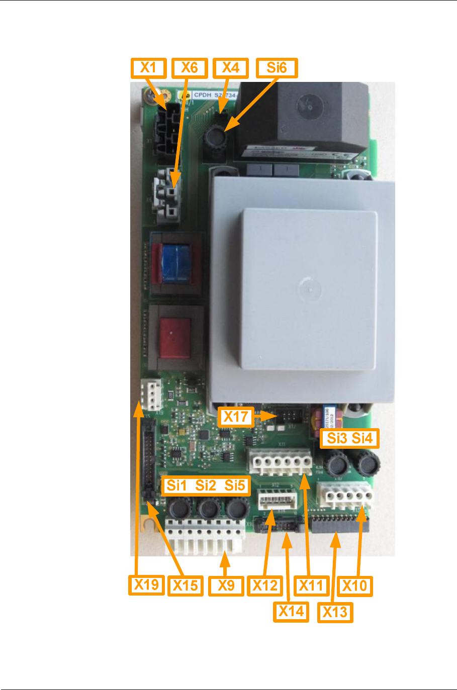
Fig. 27: CPDH assignment
Sitraffic sX
Service manual controller technology 61
Components
Siemens AG V1.0 A001a / 2014-08-20
Connector/fuse Function
X1 Power supply input
X4 Enable/disable emergency off
X6 Dimming transformer
X9 Connection to CDBH
X10 Connection to CDBH3
X11 Connector L_PED, PE
X12 Connection for APU transformer
X13 Connection for LSHS bus CDBH1
X14 Connection for LSHS bus CDBH3
X15 Connection for CBU CPDH (CPDH2)
X17 Programming connector CPDH
X19 Light-sensitive switch
Si1 Fuse LSHS1 (6.3AF) 1)
Si2 Fuse LSHS2 (6.3AF) 1)
Si3 Fuse LSHS3 (6.3AF) 1)
Si4 Fuse LSHS4 (6.3AF) 1)
Si5 Fuse L_PED (6.3AF) 1)
Si6 Fuse for dimming transformer (10AT)
Tab. 25: CPDH connector/fuse
1) Replacement fuse set with 20 pieces:
set 20 x micro fuse 6.3 A CPDH /C10 L24730-A899-A1
Pinouts:
Pin X1 Signal Function
1L_F2 Power_Supply_In
2PE PE
3 N Power_Supply_In
Tab. 26: Pinout CPDH_X1
Information
The maximum connectable LED total output is 2760 W per CPDH
Sitraffic sX
Service manual controller technology 62
Components
Siemens AG V1.0 A001a / 2014-08-20
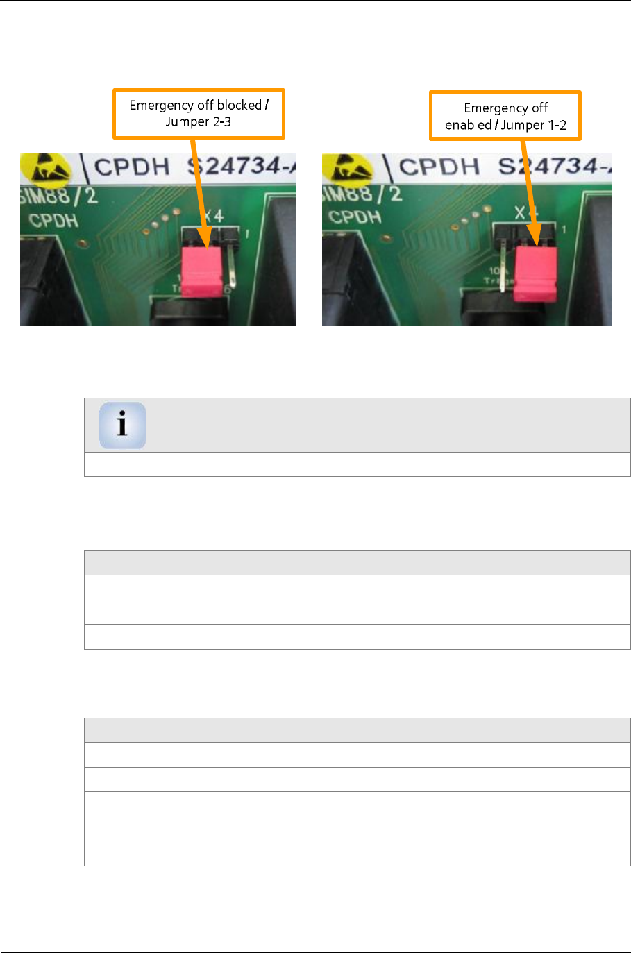
X4: Here the EMERGENCY OFF function is enabled or disabled.
Fig. 28: CPDH_X4 EMERGENCY OFF setting
Note
Usually the EMERGENCY OFF function is enabled (setting 1-2)
Pin X6 Signal Function
1L_230V L dimming transformer
2Dimm_160V Dimming voltage
3N_230N N dimming transformer
Tab. 27: Pinout CPDH_X6
in X10 Signal Function
1L_LSHS3 L for LSHS3
2 N_LSHS3 N for LSHS3
3 L_LSHS4 L for LSHS4
2 N_LSHS4 N for LSHS4
3---------- Tab. 28: Pinout CPDH_X10
Sitraffic sX
Service manual controller technology 63
Components
Siemens AG V1.0 A001a / 2014-08-20
The L_PED and N_PED power supply is needed for the connection of 230 V
confirmation devices. The L_PED power supply is protected on the CPDH
with the fuse Si5 and is accessible at connector X11. For activation see
2.22.9.
Pin X11 Signal Function
1Emergency off (optional emergency off activation with
contact to 0V)
2------ unoccupied
3L_PED Power supply for confirmation device.
4L_PED Power supply for confirmation device.
5N_PED Return conductor for confirmation
device.
6N_PED Return conductor for confirmation
device.
Tab. 29: Pinout CPDH_X11
The auxiliary power supply for LSHS1 and 2 is attached at X12. The 5-pin
connector is present on the APU transformer.
Pin X12 Signal Function
113VAC1 Auxiliary power supply LSHS1
213VAC1 Auxiliary power supply LSHS1
3
213VAC2 Auxiliary power supply LSHS2
313VAC2 Auxiliary power supply LSHS2
Tab. 30: Pinout CPDH_X12
The dimming sensor can be connected to connector X19. The dimming
function is currently not supported.
Connection of the dimming switch:
Pin X19 Signal
1+24V
2GND
3SEN_IN
4+24V
Tab. 31: Pinout CPDH_X19 DIMM connector

Sitraffic sX
Service manual controller technology 64
Components
Siemens AG V1.0 A001a / 2014-08-20
The remaining connectors are connected directly. For this one no
description of the pinout is required.
If a software update on the CPDH becomes necessary, the following cable
(CPDH Notebook) is necessary:
PDU/ CPDH charging cable, 6-pin. 2m /Cx40ES/C10 C24700-K10-B97
The cable is to be connected to CPDH_X17.
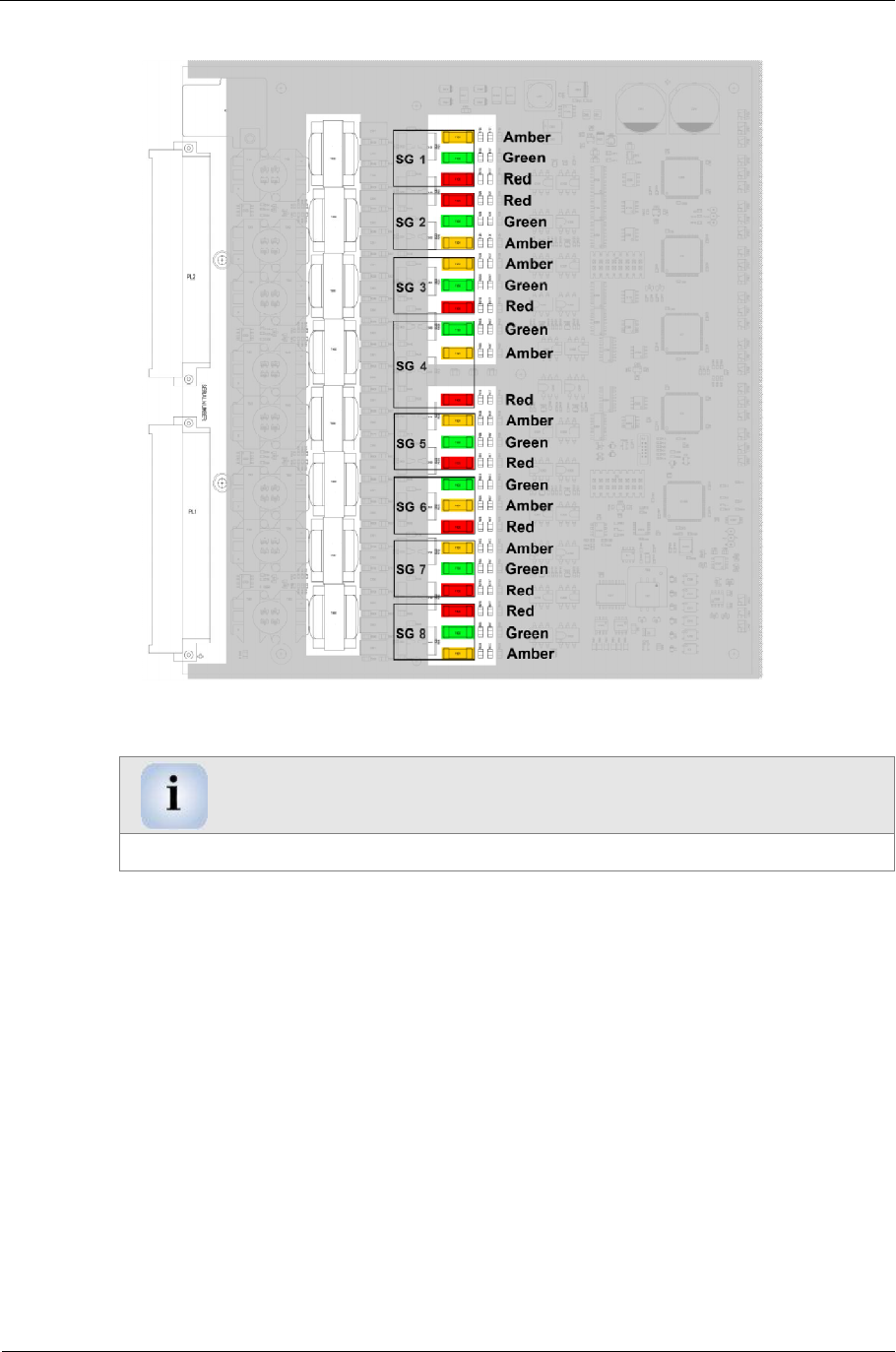
2.9. LED switch LSHS
The serial high-voltage LED switch is called LSHS (S24734-A887-A1)
because it can activate and monitor 230 -V LED signal heads. The LSHS has
the following functions:
■has an integrated B relay.
■Offers redundant current and voltage monitoring.
■operates 24 Triac outputs (230 V). (8 signal groups)
■Connection of 230 -V LED signal heads from 5W to 18W
■Up to 72- W per color output (corresponds to 4 LED heads at 18 W
each).
■up to 36 W per Red 1 and Red 2 output.
■Fuse of every triac output with 1 A
■has an LED with which the signal head color can be red, yellow and
green for each switch. (LED 1 corresponds to CDBH output 1, LED 2
output 2, etc. up to LED 24).
■Control/monitoring is supplied with 13V AC power potential-free.
■is activated serially via a potential-free RS422 interface.
■has an additional RS422 interface for activating additional LSHS in
serial mode.
Sitraffic sX
Service manual controller technology 65
Components
Siemens AG V1.0 A001a / 2014-08-20
■has 4 electrically-isolated digital inputs via optocouplers.
■Optional electronic load (CEW) on LSHS can be plugged in.
Warning
Connecting incandescent bulbs is not possible
The LSHS assembly set is called:
LSHS Set /C10 L24734-A887-A10
Fig. 29: View of LSHS fuses

Sitraffic sX
Service manual controller technology 66
Components
Siemens AG V1.0 A001a / 2014-08-20
The LSHS module has 24 LED switches / with 32 outputs (Red1, Red2,
Yellow and Green). In each case three outputs for the colors red, yellow
and green are permanently assigned to a signal group.
For each LSHS module a CDBH backplane is required, on which the
terminals for the connection of the LED signal heads including the return
conductors are located. The CDBH is also used for carrying the control
signals and power supply to the LSHS module. For the sX controller two
CDBH/LSHSs can be installed in the main chassis and two CDBH/LSHSs in
the add-on chassis.
The CBU communicates with the LSHS modules 1-4 via the LS1 bus. This is
an RS422 bus with a transmission speed of approx. 600 kBit/s. The master
is the CHX processor on the CBU that asks for the status of the LSHS
modules (slaves) every network cycle. The LS1 bus is guided across the
CPDH and the backplane CDBH1 to the LED switches LSHS1. Here, the
information concerning LSHS1 is coupled and decoupled. The bus is guided
in amplified form to the next LSHS. (The LSHS modules are thus connected
in series at the LS bus.
The LED switches need a potential-free alternating current of 13 V AC for
their internal logic. For this an APU transformer is provided which feeds the
LED switches in the main chassis via CPDH and CDBH over two separate
windings.
A second APU transformer, which feeds the LED switches, is provided in the
add-on chassis. For structure see Fig. 2: Frame structure for sX-H and sX-
Hx.
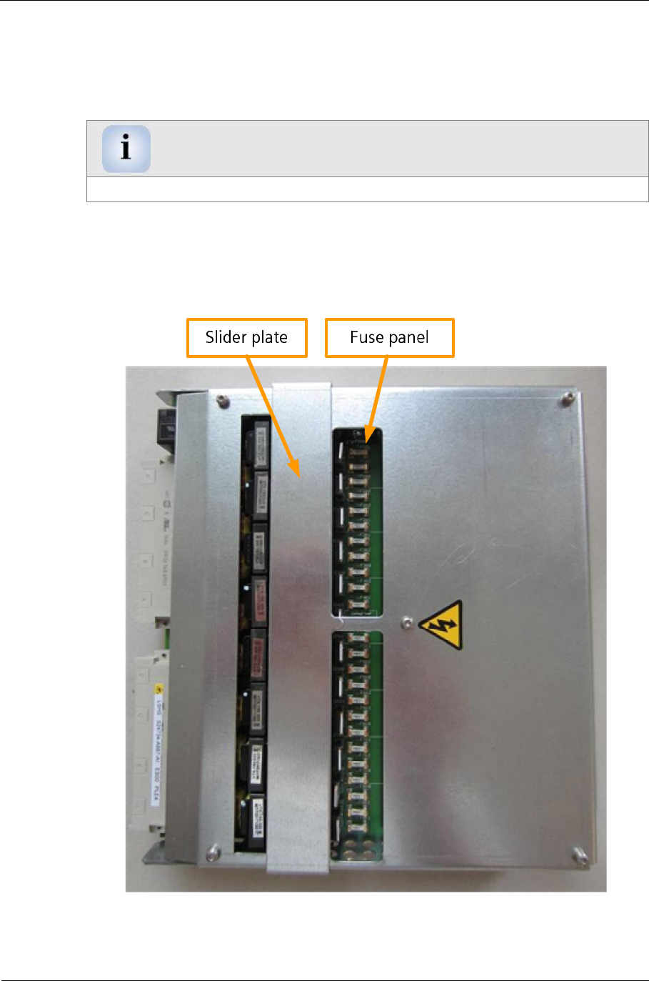
The fuses of the LSHS can only be accessed if the module is removed. Then
the slider plate can be slid back and fuse device is accessible. When
plugged in the slider plate is closed
Set 20 x SMD fuse 1 A LSHS/C10 L24730-A899-A2
Sitraffic sX
Service manual controller technology 67
Components
Siemens AG V1.0 A001a / 2014-08-20
Fig. 30: LSHS fuse assignment
Note
The fuse arrangement is not sequential
The fuse labels are coded as follows:
Fx0y. Where:
■x is the number of the signal group
■y is the color.
The color code is:
0è red
1è yellow
2è green
Example: F101 is signal group 1, yellow
Sitraffic sX
Service manual controller technology 68
Components
Siemens AG V1.0 A001a / 2014-08-20
2.10. CEW module
The CEW (S24734-A898-A1) is an electronic load module for the LSHS. This
can be if necessary in some cases, if external power supplies appear due to
capacitive linking of wire to wire in the outdoor system. The module affects
all outputs. This module is to be mounted on the rear side of the LSHS. For
this, the multipoint male connectors of the CEW are to be carefully plugged
into the LSHS and fastened with 3 screws (CEW component side to the
LSHS).
The CEW assembly set is as follows:
CEW 230 V Set L24730-E821-A2
Fig. 31: CEW next to LSHS
CEW LSHS

Sitraffic sX
Service manual controller technology 69
Components
Siemens AG V1.0 A001a / 2014-08-20
2.11. CDBH
The CDBH (S24734-A872-A1) is the backplane for the LSHS. It establishes
the connection from the LSHS module to the outdoor system.
The CDBH has the following functions:
■Connection of controllers 1-4: Red1, red2, red unmonitored, yellow,
green
■Connection of controllers 5-8: Red1, red2, yellow, green
■3 spring terminals are present for each color signal.
■On the return conductor block (dark gray in the CDBH) 24 return
conductors can be connected. Up to 4 A per return conductor block.
■For each CDBH a PE block with 16 terminals is to be installed onto the
top-hat rail. For CDBH 1 and CDBH 2 this takes place at the bottom left
in the main chassis. See, Fig. 2, no. 20. The PE block of CDBH 3 and
CDBH 4 is to be installed onto the right top-hat rail in the main chassis,
sees Fig. 2 no. 17.
The CDBH assembly set is as follows:
CDBH accessories /C10 L24734-A872-A10
For correct addressing of the LSHS modules, the address must be set on the
CDBH. For this there is an address field (X15) with ADDR0 to ADDR3 in the
top area. Here the appropriate address must be scratched. The signals to be
scratched are shown with an X.
LSHS number ADDR3 ADDR2 ADDR1 ADDR0
1 X
2 X
3 X X
4 X
5 X X
6 X X
7 X X X
8 X Tab. 32: CDBH address setting
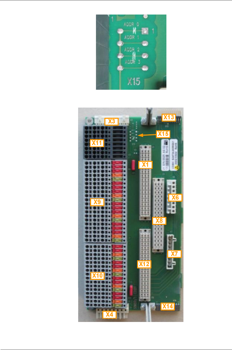
Sitraffic sX
Service manual controller technology 70
Components
Siemens AG V1.0 A001a / 2014-08-20
Fig. 32: Photo CDBH X15 (here address 5 set)
Fig. 33: CDBH view
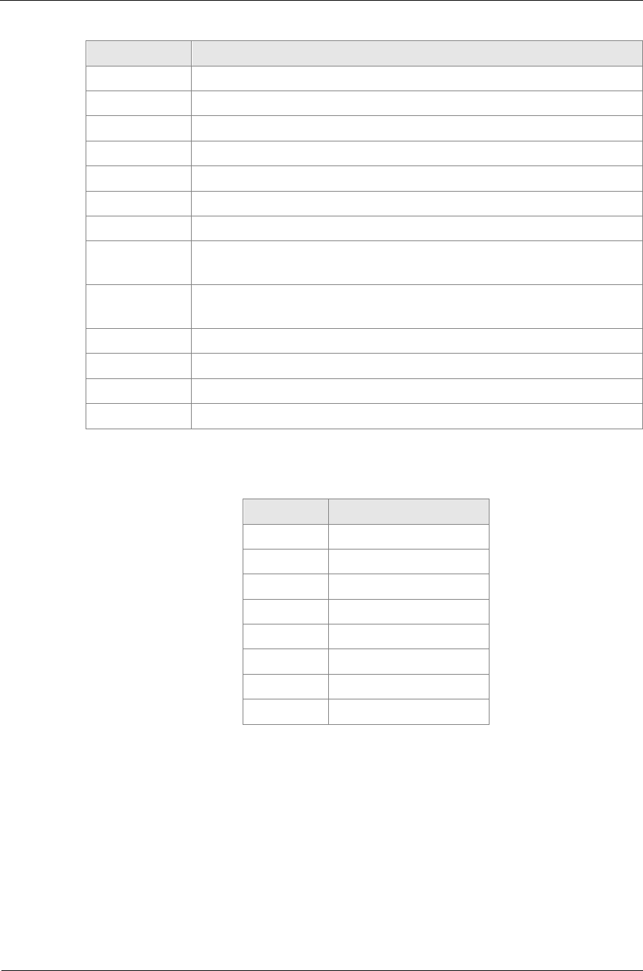
Sitraffic sX
Service manual controller technology 71
Components
Siemens AG V1.0 A001a / 2014-08-20
Connector Connector function
X1 LSHS module
X2 LSHS module
X3 Power supply
X4 Power supply redirection
X6 Analog inputs (not in level 2)
X7 Digital inputs (not in level 2)
X8 CEW module
X9 Terminal block for controllers 1-4 with unmonitored red
output (3 x red)
X10 Terminal block for controllers 5-8 with unmonitored red
output (2 x red)
X11 Return conductor block N_LED
X13 Serial LS bus
X14 Serial LS bus
X15 Address patch field
Tab. 33: CDBH view
X6 Pin Signal
1Torroid1
2 Torroid1
3 Torroid2
4 Torroid2
5 Torroid3
6 Torroid3
7 Torroid4
8 Torroid4
Tab. 34: CDBH X6 assignment
Up to four external switches or buttons can be connected to the X7.
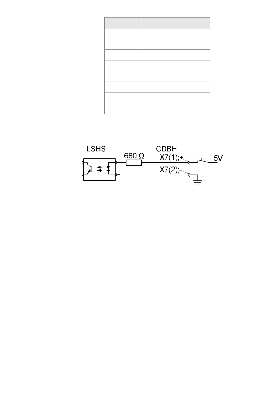
Sitraffic sX
Service manual controller technology 72
Components
Siemens AG V1.0 A001a / 2014-08-20
X7 Pin Signal
1DIG_IN1+
2 DIG_IN1-
3 DIG_IN2+
4 DIG_IN2-
5 DIG_IN3+
6 DIG_IN3-
7 DIG_IN4+
8 DIG_IN4-
Tab. 35: CDBH X7 assignment
Fig. 34: Sample wiring of the digital inputs
2.12. CPA module
In the add-on chassis the CPA (S24734-A883-A1) is necessary for the
coupling of the 3rd or 7th CDBH including the corresponding LED switches.
The CPA is a small printed circuit board with three plug connectors which
provides the CDBH (and therefore the LED switches) with an interface
electrically and mechanically identical to the CPDH. For the power supply to
the LED switches in the add-on chassis the large APU transformer is
necessary.
2.12.1. Installation for sX-H and sX-Hx
The CPA is used for 230-V devices with CDBH.
For this there is the following installation set:
For installation the following is necessary:
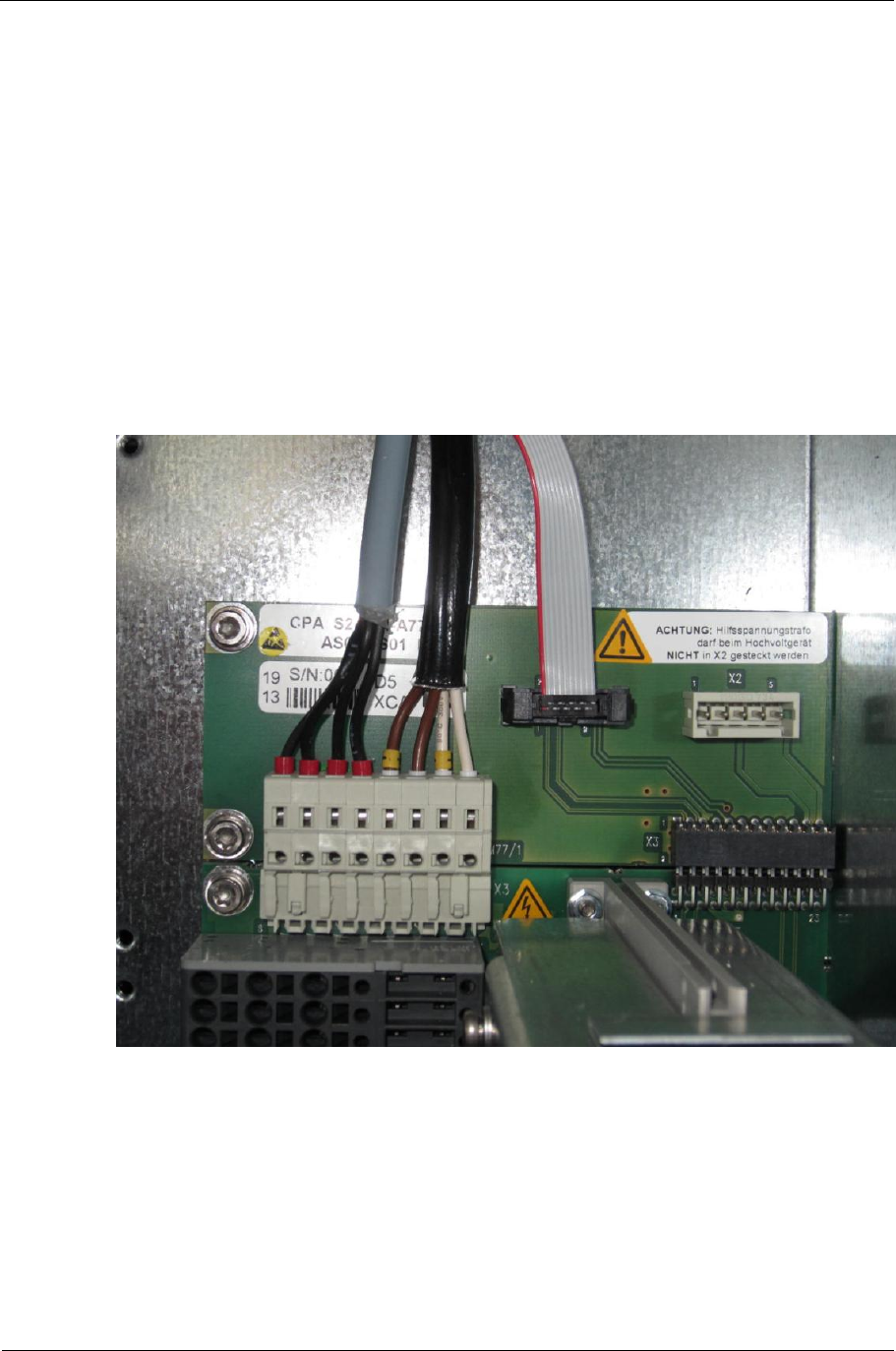
Sitraffic sX
Service manual controller technology 73
Components
Siemens AG V1.0 A001a / 2014-08-20
■CPA Power Distribution Adapter high/C10 L24730-E821-A210
■Transformer Set 50VA /C10 L24730-E810-A45
If only three LSHSs are used in the device, the 3rd LSHS with CPA can also
be installed on the installation location of the 4th LSHS, (the same applies
for the 7th LSxS with CPA). The existing connecting cables and the
mechanics are appropriate for both installations. In this case, additional
CLB installation locations are available on the left side.
Fig. 35: Photo CPA CDBH connection
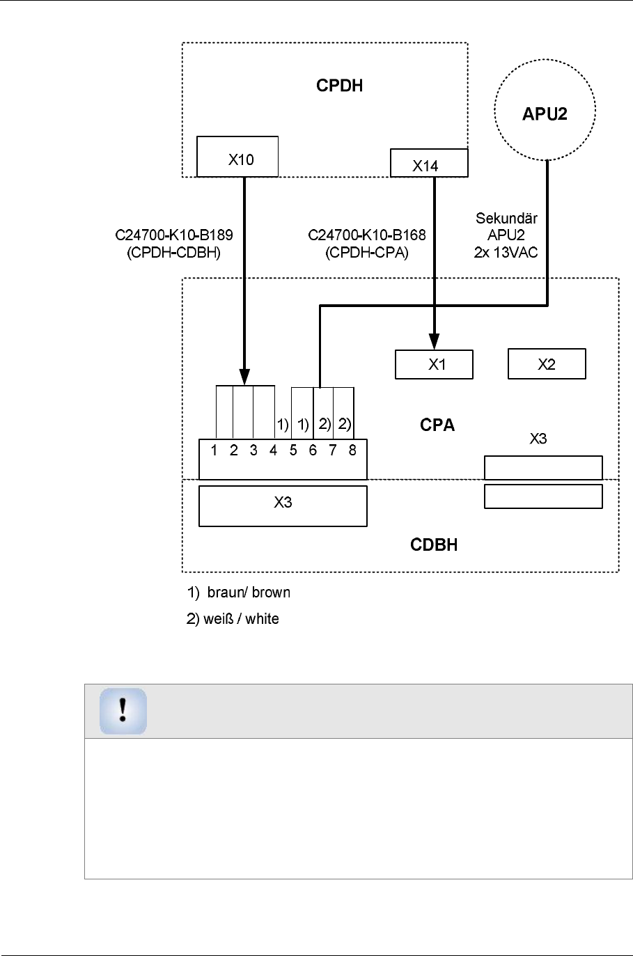
Sitraffic sX
Service manual controller technology 74
Components
Siemens AG V1.0 A001a / 2014-08-20
Fig. 36: Activation of CPA-CDBH
Warning
WARNING: The connector of the auxiliary power supply transformer may NOT
be connected to CPA_ X2 for the high-voltage device
(sX-H).
■For the activation the 5-pin connector must be removed from the APU2
transformer.
■The wires are to be connected at the X3 connector of the CDBH as
shown.

Sitraffic sX
Service manual controller technology 75
Components
Siemens AG V1.0 A001a / 2014-08-20
2.13. sX-Hx device
For more than 32 controllers you will need a second cabinet. This way up
to 64 controllers are possible. This device is known as sX-Hx.
See the following overviews:
■For the mechanical structure see Fig. 2
■For 230 -V distribution see Fig. 9
Then the 2nd cabinet contains:
■Main/add-on chassis
■The 2nd CPDH
■LSHS 5-8
■APU transformer
■Power distributor
■Additional CLB places
■The maximum total output of the system may not exceed 2760 W, so
that the same utility compartment can be used.
The modules CPDH/CDBH/LSHS/CLB are to be installed in the same places as
in the 1st cabinet. At the CTB location it can already be started with one
CLB.
Changes in the main chassis:
■In the 1st main chassis the LED signal head fuse (F2) for the 2nd CPDH
is to be changed from single-pin 16AB to 2-pin 16AB.
■For the 2nd LS bus (LSHS5-8) the CEB module is to be plugged into the
CBU.
For the serial connection of the 2nd CPDH the wire
C24700-K10-B181 is necessary.
It connects CBU.X19è1st CPDH.X15 è CEB.X65 è2nd CPDH.X1
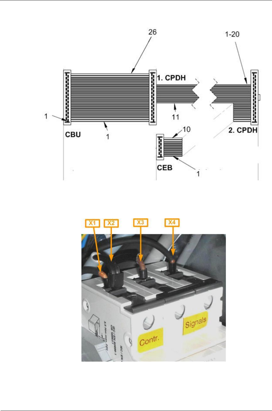
Sitraffic sX
Service manual controller technology 76
Components
Siemens AG V1.0 A001a / 2014-08-20
Fig. 37: Wire C24700-K10-B181
Fig. 38: Fuse connection sX-Hx
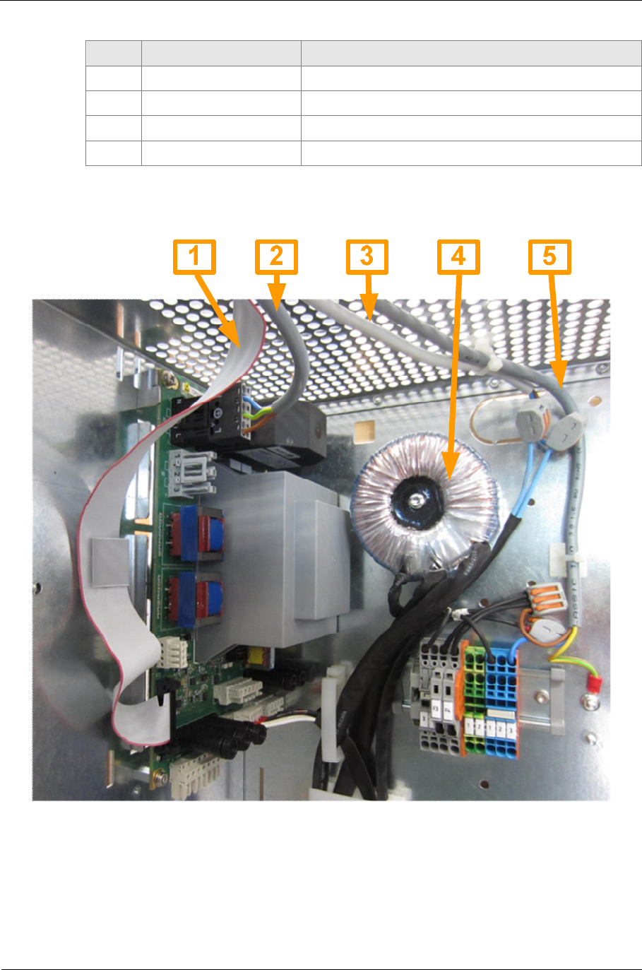
Sitraffic sX
Service manual controller technology 77
Components
Siemens AG V1.0 A001a / 2014-08-20
No. Part number Connection
1C24700-K10-B198 F1 è2nd power distributor F5/F6
2C24700-K10-B179 F1 è F3/F4
3C24700-K10-B188 F2.1 è 1st CPDH.X1
4C24700-K10-B197 F2.2 è.2nd CPDH.X1
Tab. 36: Fuse connection sX-Hx
Fig. 39: Installation of 2nd CPDH
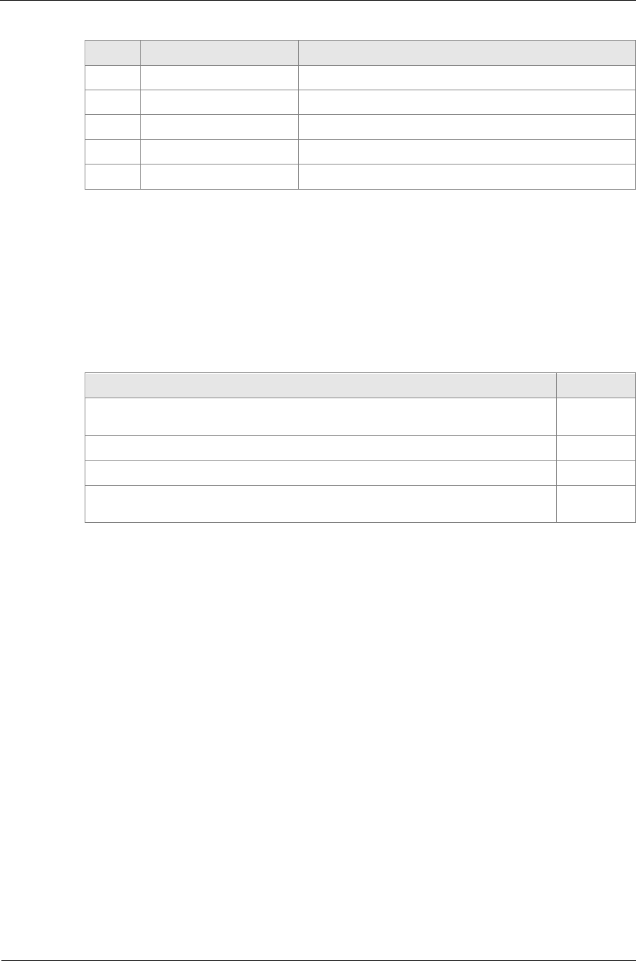
Sitraffic sX
Service manual controller technology 78
Components
Siemens AG V1.0 A001a / 2014-08-20
No. Part number Connection
1C24700-K10-B181 CBU è CPDH1 è CPDH2 è CEB
2C24700-K10-B197 F2.2 è CPDH2
3C24700-K10-B185 Optional: APU è CLA2
4V24068-Z5045-A1 Transformer CPDx2_X1
4C24700-K10-B198 F1 è Power distributor 2
Tab. 37: Installation of 2nd CPDH
2.14. CLB installation locations
The IO add-on locations available in the chassis are called CLB installation
locations. These can however be equipped with different functions, but not
all functions are attached at the IO bus.
Function IO Bus
IO add-on with CLB backplane ( for SLD4, CIE,CIO, DIB-E) yes
IO extension with CIAB backplane (for CIAC) yes
Add-on for auxiliary power supply (24V DC, 48 V DC, 24V AC) No
Add-on for the special adapter CUA No
Tab. 38: CLB installation locations
The I/O add-on in sX takes place from below at the module that can be
connected to the CTB. Here, the modules that are connected to the IO bus
(CLB and CIAB) are to be attached first. The modules are connected via the
IO bus to the CBU. For the modules CLB/CIAB there is a case that holds the
relevant backplanes and modules. Each backplane can hold 2 modules.
Installation of the modules not connected at the IO bus (power supply and
CUA) takes place toward the end of the installation locations.
2.15. CLB
The size of a CLB installation location for the chassis of the sX device is
determined by the dimensions of the CLB (S24734-A879-A1).
In the first main chassis there are 3 CLB installation locations if counting
the two installation locations for detector and IO modules on the CBU. In

Sitraffic sX
Service manual controller technology 79
Components
Siemens AG V1.0 A001a / 2014-08-20
the first add-on chassis there is room for a maximum of 7 CLB installation
locations.
Altogether there are thus 10 CLB installation locations.
Actually, a total of 18 modules can be operated in the main and add-on
chassis together. CLB installation locations not assigned CLBs/CIABs cannot
be assigned accessories such as auxiliary power supplies.
When planning it is to be noted that the CLB installation locations overlap
with the LED switch installation locations in the add-on chassis. Depending
upon number and affixing location of the LED switch backplane the
number of available CLB installation locations may be reduced.
For the second main chassis as well 3 CLB installation locations are
available because a CLB can already be installed there at the CTB location.
Modules up to a current consumption of 60 mA are supplied from the CBU
via the backplane.
Modules with higher current consumption must be supplied via the spring
terminals X6. When using the CIE/CIO the terminals have the designation
U+ and U-.
All modules that are to be plugged into a CLB are connected via IO bus 1 or
IO bus 2 to the master bus (processor CBC) on the CBU. Each module that is
connected to an IO bus needs a unique address. The setting of the DIP
switch on the CLB specifies the addresses of both plug-in locations. The left
plug-in location (X4) receives the even address and the right plug-on
location (X5) the odd address.
When making the setting, proceed as follows:
For both installation locations X39 and X40 on the CBU the addresses 14
and 15 are permanently set. The designation CLB1 is assigned to these two
installation locations. For the CLBs connected via the CTB the addresses are
set in sequentially increasing order. Tab. 39: Setting of the addresses with
IO bus 1 shows the setting of the addresses in the first main and add-on
chassis. The setting for the second main and add-on chassis is described in
Tab. 40: Setting of the addresses with IO bus 2. Because the modules in the
second chassis communicate via IO bus 2, the same physical addresses are
used as with the first chassis. For the use of IO bus 2 a CEB module is
necessary. See 0.
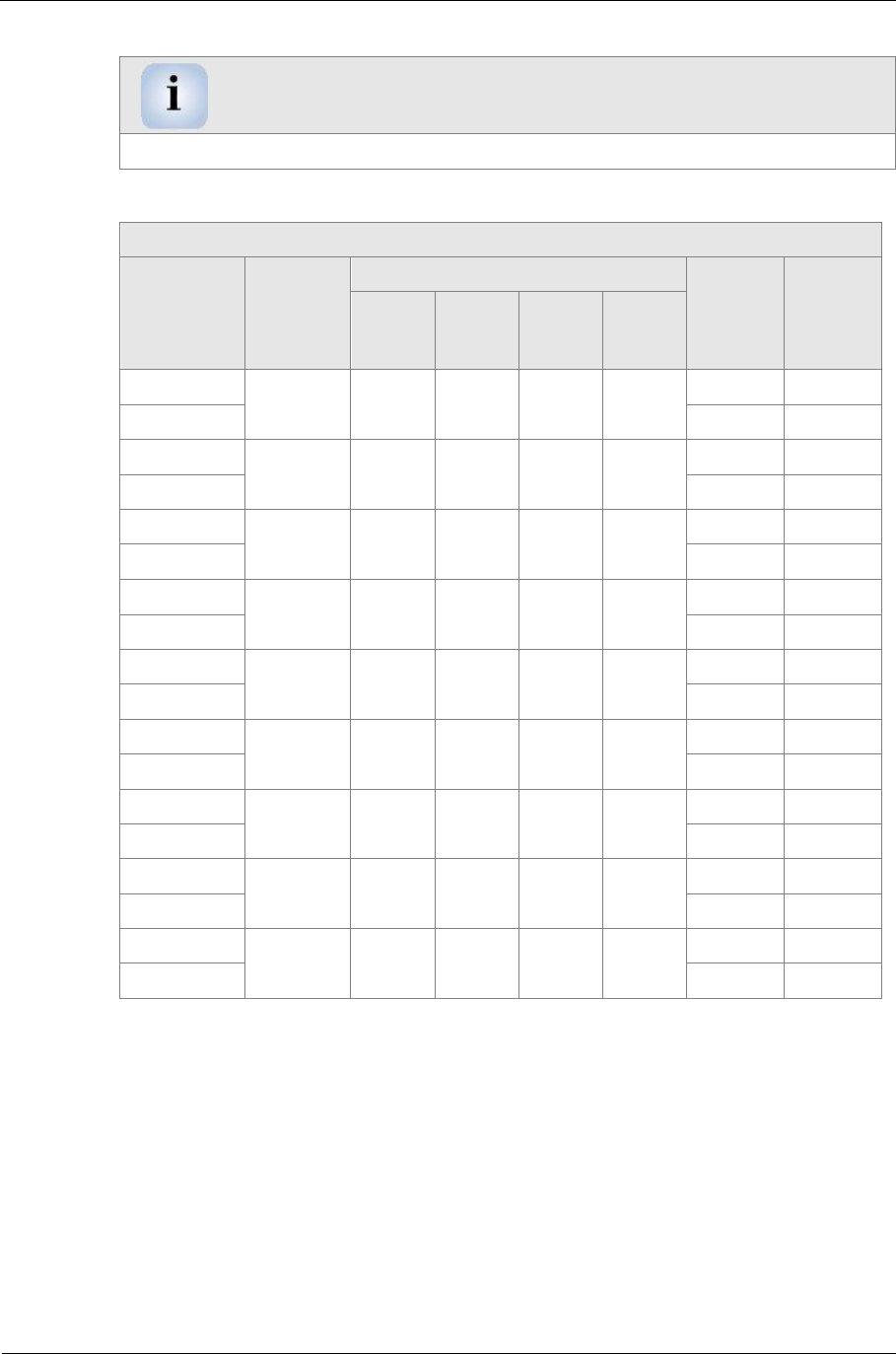
Sitraffic sX
Service manual controller technology 80
Components
Siemens AG V1.0 A001a / 2014-08-20
Warning
The address 0 is used for broadcasts and therefore may not be modified!
Address assignment in the 1st main and add-on chassis for IO bus 1
Module
address Backpl
ane Address setting CLB Plug-
in
locati
on
Phys.
Addr.
S1-4 S1-3 S1-2 S1-1
0CBU
/CLB1 -- -- -- -- X39 14
1 X40 15
2CLB2 Off On On On X4 16
3X5 17
4CLB3 Off On On Off X4 18
5X5 19
6CLB4 Off On Off On X4 20
7X5 21
8CLB5 Off On Off Off X4 22
9X5 23
10 CLB6 Off Off On On X4 24
11 X5 25
12 CLB7 Off Off On Off X4 26
13 X5 27
14 CLB8 Off Off Off On X4 28
15 X5 29
16 CLB9 Off Off Off Off X4 30
17 X5 31
Tab. 39: Setting of the addresses with IO bus 1
When installed the plug-in locations X4 (CLB) and X39 (CBU) are at the left
and the plug-in locations X5 (CLB) and X40 (CBU) at the right.
The 10th CLB installation location is intended for special installations such
as power supply and cannot be addressed at the bus and is not included in
bus addressing.

Sitraffic sX
Service manual controller technology 81
Components
Siemens AG V1.0 A001a / 2014-08-20
Address assignment in the 2nd main and add-on chassis for IO bus 2
Module
address
Back
plane Address setting CLB Plug-
in
locati
on
Phys.
Addr.
S1-4 S1-3 S1-2 S1-1
18 CLB10 Off On On On X4 16
19 X5 17
20 CLB11 Off On On Off X4 18
21 X5 19
22 CLB12 Off On Off On X4 20
23 X5 21
24 CLB13 Off On Off Off X4 22
25 X5 23
26 CLB14 Off Off On On X4 24
27 X5 25
28 CLB15 Off Off On Off X4 26
29 X5 27
30 CLB16 Off Off Off On X4 28
31 X5 29
32 CLB17 Off Off Off Off X4 30
33 X5 31
Tab. 40: Setting of the addresses with IO bus 2
When installed the plug-in locations X4 (CLB) are at the left and the plug-in
locations X5 (CLB) at the right.
The 9th and 10th CLB installation location in the 2nd main chassis is
intended for special installations such as power supply and cannot be
addressed at the bus and is not included in bus addressing.
For CLB module and case the following sets are required:
■CLB bracket set /C10 L24730-E811-A100
■CLB C10 Loop Detector Backplane S24734-A879-A1
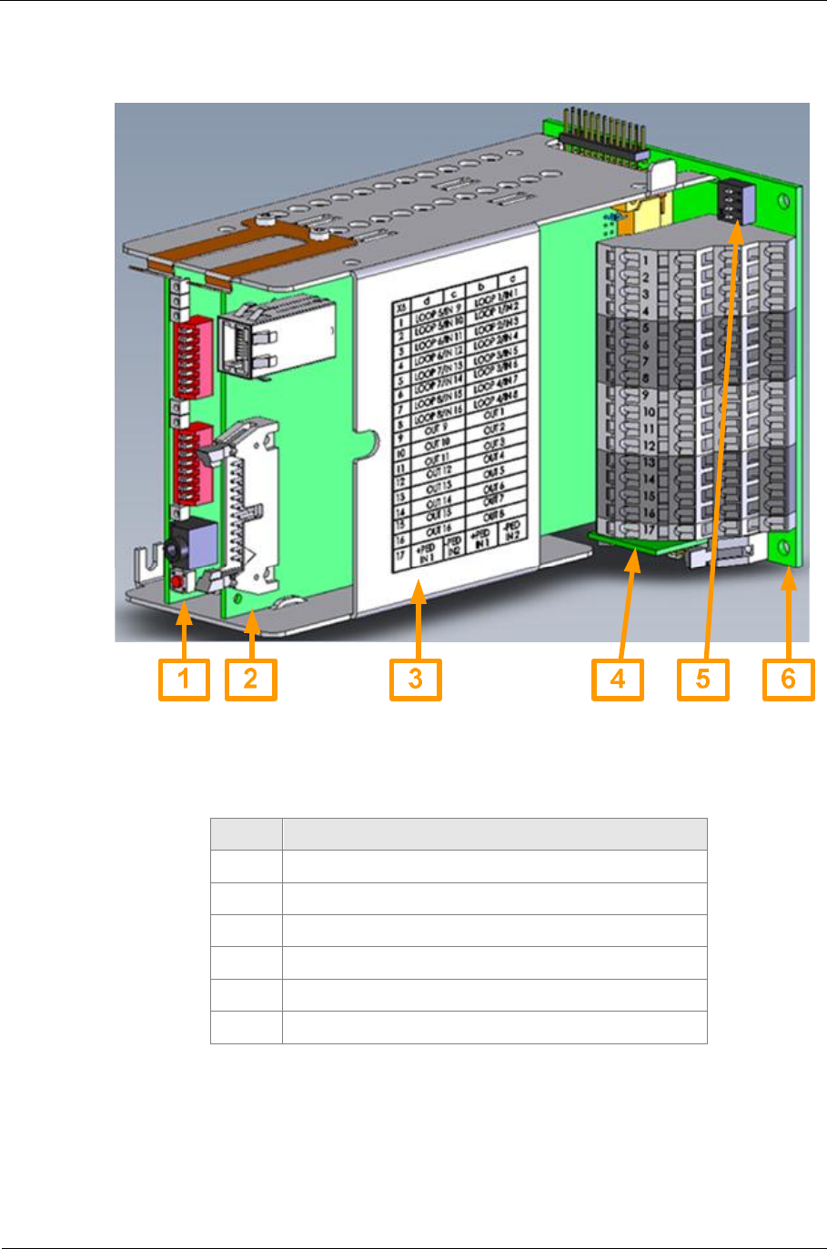
Sitraffic sX
Service manual controller technology 82
Components
Siemens AG V1.0 A001a / 2014-08-20
The CLB installed with housing has the following appearance:
Fig. 40: CLB housing (configuration example)
No. Description
1e.g. SLD4 module
2e.g. CIE/CIO module
3CLB housing with inscription
4CLBT module 1)
5CLB address switch
6CLB module
Tab. 41: CLB with configuration example
1) The CLBT module (S24734-A891-A1) is to be plugged in once per I/O bus
and with the last module there.
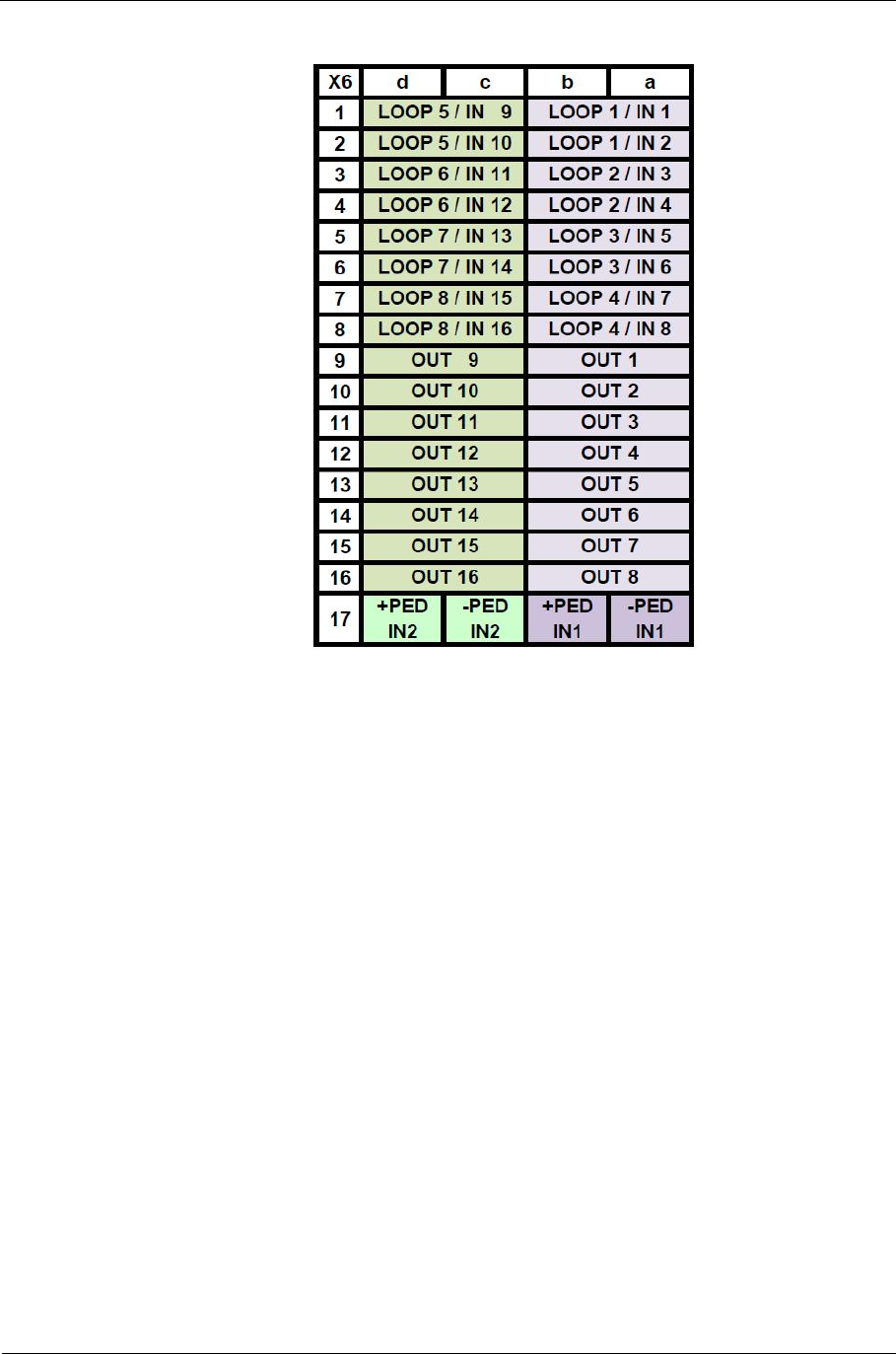
Sitraffic sX
Service manual controller technology 83
Components
Siemens AG V1.0 A001a / 2014-08-20
Tab. 42: CLB inscription
Since the terminal assignment cannot be represented on the CLB, a sticker
with the terminal assignment is affixed to the housing. The sticker is
included in the CLB assembly set. In the CLB the items a/b and c/d,
respectively, are connected in parallel (except +PED/-PED) in order to have
2 terminals when activating buttons and confirmations.
the left plug-in location (X4) goes to the terminals a/b.
The right plug-in location (X5) goes to the terminals c/d.
In the CLB the following modules can be plugged in:
■SLD4 (loop detector)
■CIE (I/O module)
■CIO (variant CIE module)
■DIP-E (video activation)
■DIB-P (video activation being prepared
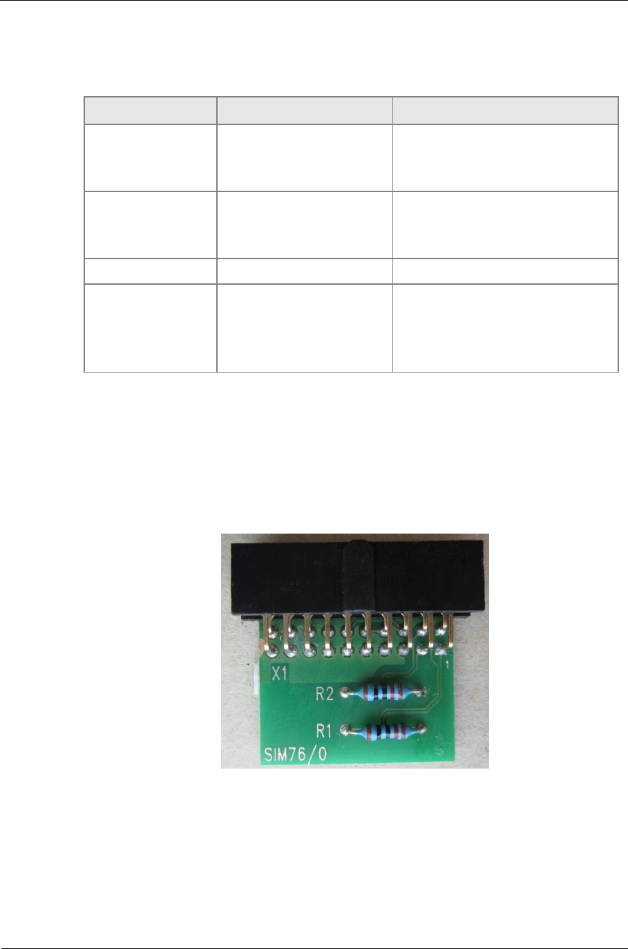
Sitraffic sX
Service manual controller technology 84
Components
Siemens AG V1.0 A001a / 2014-08-20
Any combinations of these modules can be plugged in the CLB. For the
modules to be plugged in the following material is necessary.
Funktion Material. Erläuterung
C10 CIE S24734-A877-A1
L24730-E814-A2
C24700-K10-B215
CIE module
24 V power supply
Cable
C10 CIO S24734-A890-A1
L24730-E814-A2
C24700-K10-B215
CIO module 24V
Power supply
Cable
C10 SLD4 S24763-A82-A6 SLD4 module
C10 DIB-E
L24730-E814-A1
ZNX:DET-089-000151
L24730-E814-A2
L24730-E814-A14
Assembly set DIP-E
DIB-E module
24 V power supply
SV mounting brackets
Tab. 43: CLB configuration
2.16. CLBT module
Die CLBT module (S24734-A891-A1) must be plugged in to the last
CLB/CIAB module in the IO bus. See Fig. 40: CLB housing, number 4.
Fig. 41: CLBT module
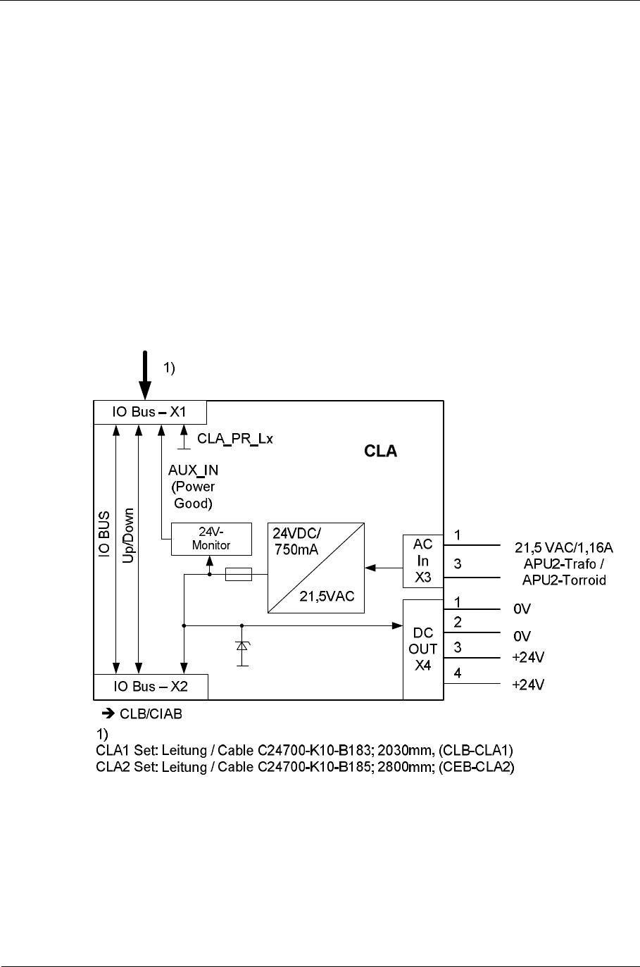
Sitraffic sX
Service manual controller technology 85
Components
Siemens AG V1.0 A001a / 2014-08-20
2.17. CLA module
The CLA (S24734-A878-A1) module serves to couple the I/O bus from
above to the CLB modules in the add-on chassis and to generate the
24V for the add-on chassis. The CLA module is to be attached at the top on
the CLB cage. When attaching, pressure can only be applied to the plastic
pin. Depending upon installation there may be 2 sets with accessories:
C10 CLA1 set L24730-E812-A3
(connection main chassis CLBx-X1 to the add-on chassis CLA_X1)
C10 CLA2 Set L24730-E812-A
(connection 1st main chassis CEB_X60 to 2nd main chassis CLA_X1. The
required CEB module is not included in the set)
Fig. 42: CLA structure
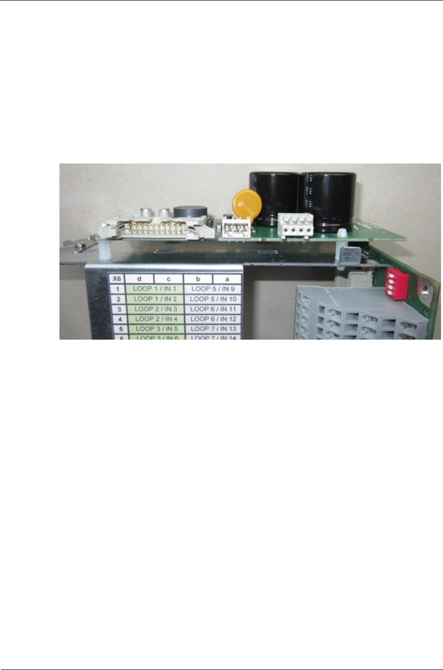
Sitraffic sX
Service manual controller technology 86
Components
Siemens AG V1.0 A001a / 2014-08-20
The CLA produces +24V/750mA for the plugged-in modules. The 24V are
monitored and reported to the CBU. The current consumption amounts to
60mA for each SLD4, CIE; CIAC module. Unused current can be removed at
X4 (VOUT) and used internally. For a power supply for generation of 24V
DC, 21.5VAC is needed from the large APU transformer (V24068-Z5045-
A1). This is already available with a device with 3 or 4 LSHSs. Otherwise the
transformer set is necessary:
Transformer set 50 VA /C10 L24730-E810-A45
Fig. 43: CLA module installed
2.18. SLD4 loop detector module
The loop module SLD4 (S24763-A82-A6) can be plugged into the CLB and
CBU
At the SLD4 4 detection loops can be connected.
For details see SLD4 description.
Here there is the description of the SLD4 installation in the CLB. There are 2
SLD4 modules the can be plugged in per CLB.

Sitraffic sX
Service manual controller technology 87
Components
Siemens AG V1.0 A001a / 2014-08-20
Installation location
on CLB assigned
SLD4
X5 X4
Terminal block X6
no. / row d c b a
1Loop 5a Loop 1a
2 Loop 5b Loop 1b
3 Loop 6a Loop 2a
4 Loop 6b Loop 2b
5 Loop 7a Loop 3a
6 Loop 7b Loop 3b
7 Loop 8a Loop 4a
8 Loop 8b Loop 4b
9-- --
10 -- --
11 -- --
12 -- --
13 -- --
14 -- --
15 -- --
16 -- --
17 -- --
Tab. 44: Terminal assignment of the CLB when SLD4 equipped
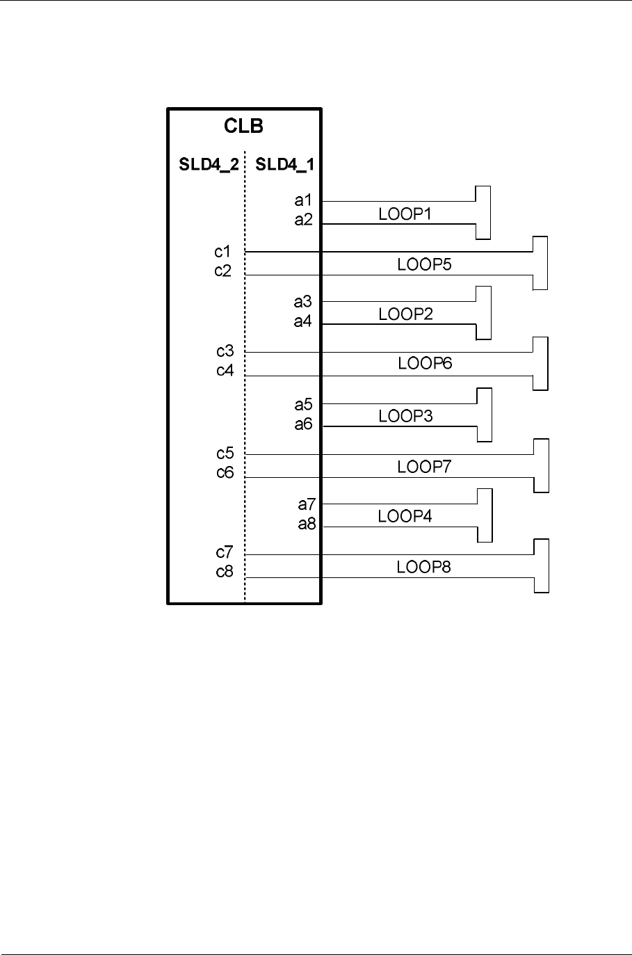
Sitraffic sX
Service manual controller technology 88
Components
Siemens AG V1.0 A001a / 2014-08-20
The connection of SLD4 modules in the CBU is described for the CTB. See
Tab. 15
Fig. 44: Loop activation
2.18.1. UPLINK/DOWNLINK
Besides their IO bus (to the CBU) the SLD4 modules have an additional
communication interface which allows the SLD4 modules to communicate
with one another. This is accomplished without the help of an external
processor and is carried out automatically by the loop detector modules.
Via this detector connection the following functions are implemented:
■Automatic frequency selection of the loops. This allows the master
SLD4 module to set the optimal frequency for all loops.
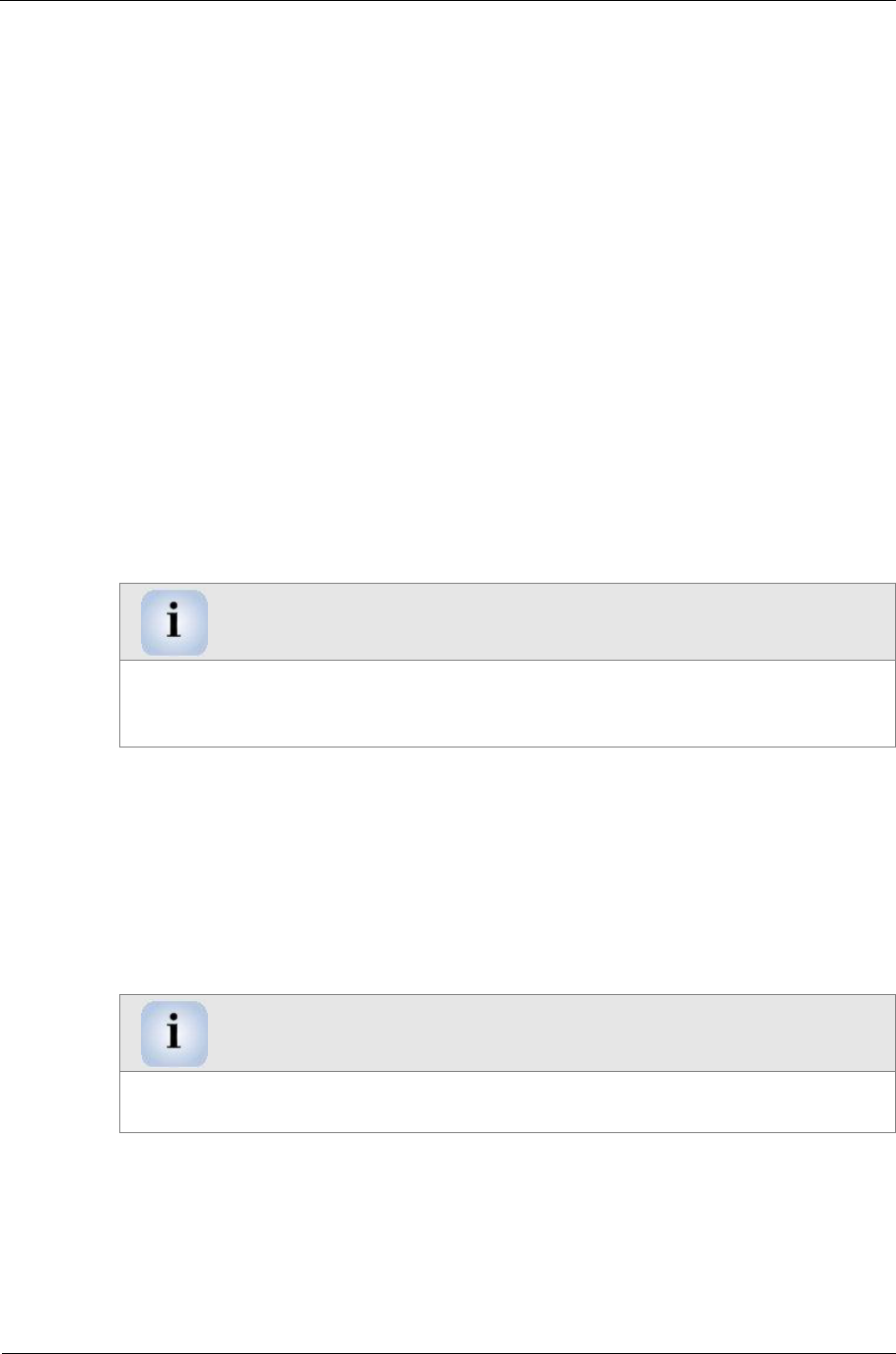
Sitraffic sX
Service manual controller technology 89
Components
Siemens AG V1.0 A001a / 2014-08-20
■All SLD4 can be reset by pressing the reset button on the master
module and all LEDs turn on/off.
■The PC SLD4 tool can communicate with all SLD4s (if the SLD4 master
is connected to the PC). This allows simultaneous collection of log files,
car data and car simulation for all detectors.
For this, it is important that the SLD4 modules can communicate with one
another. This requires that the UP and DNLINK signals are not disrupted. As
you can see in Fig. 45 the IO modules have to be plugged in consecutively
to each mounting slot (the detector link is a point-to-point connection and
not a bus). In this case the first module on the UPLINK bus takes the master
role; all other modules are slaves which can be controlled by the master.
It is not mandatory to insert only SLD4 modules consecutively; other
modules suited for the IO slot like CIE, CIO and DIB-E also connect the
respective signals correctly and loop through the bus.
Disruption UPLINK/ DOWNLINK
If a SLD4/CIE/CIO/DIB-E module is not set, UPLINK and DOWNLINK are
disrupted and the functionality is not available. Thus, another or several other
modules are set as master.
The same applies to the IO backplanes; here alternative backplanes like the
CIAB also can replace a CLB at any position without constraining the
functionality of the detector link. In the CIAB backplane the loopthrough of
the UPLINK and DOWNLINK signals is already available in the CIAB making
the CIAC redundant.
CLB slot change in mounting a power supply
If you mount a power supply in the CLB4 slot the CLB4 slot moves to the add-
on chassis and is there the top level module.
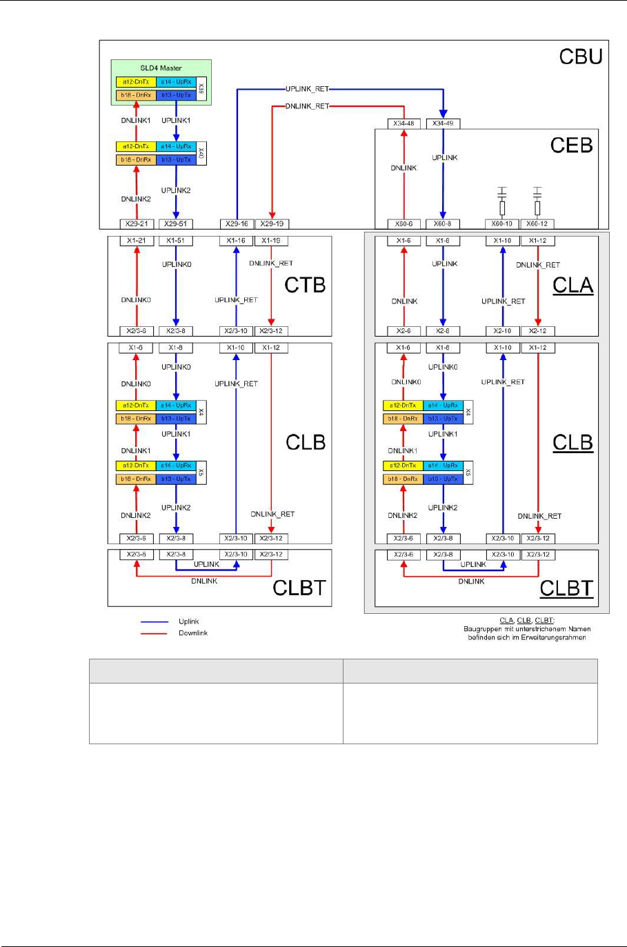
Sitraffic sX
Service manual controller technology 90
Components
Siemens AG V1.0 A001a / 2014-08-20
German English
Baugruppen mit unterstrichenem
Namenbefinden sich im
Erweiterungsrahmen
Modules with underlined names
are located in the add-on frame
Fig. 45: Schematic structure uplink / and downlink
Schematic structure of the UPLINK and DNLINK wiring in the sX; the SLD4
master is marked green.
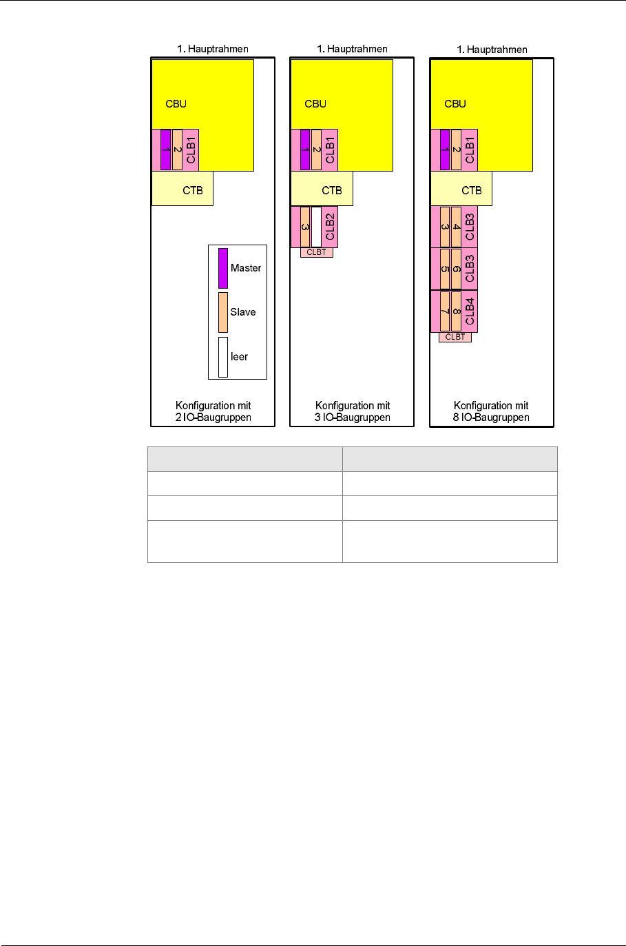
Sitraffic sX
Service manual controller technology 91
Components
Siemens AG V1.0 A001a / 2014-08-20
German English
Hauptrahmen Main chassis
Leer empty
Konfiguration mit IO-
Baugruppen Configuration with IO
modules
Fig. 46: CLB method of counting in main chassis
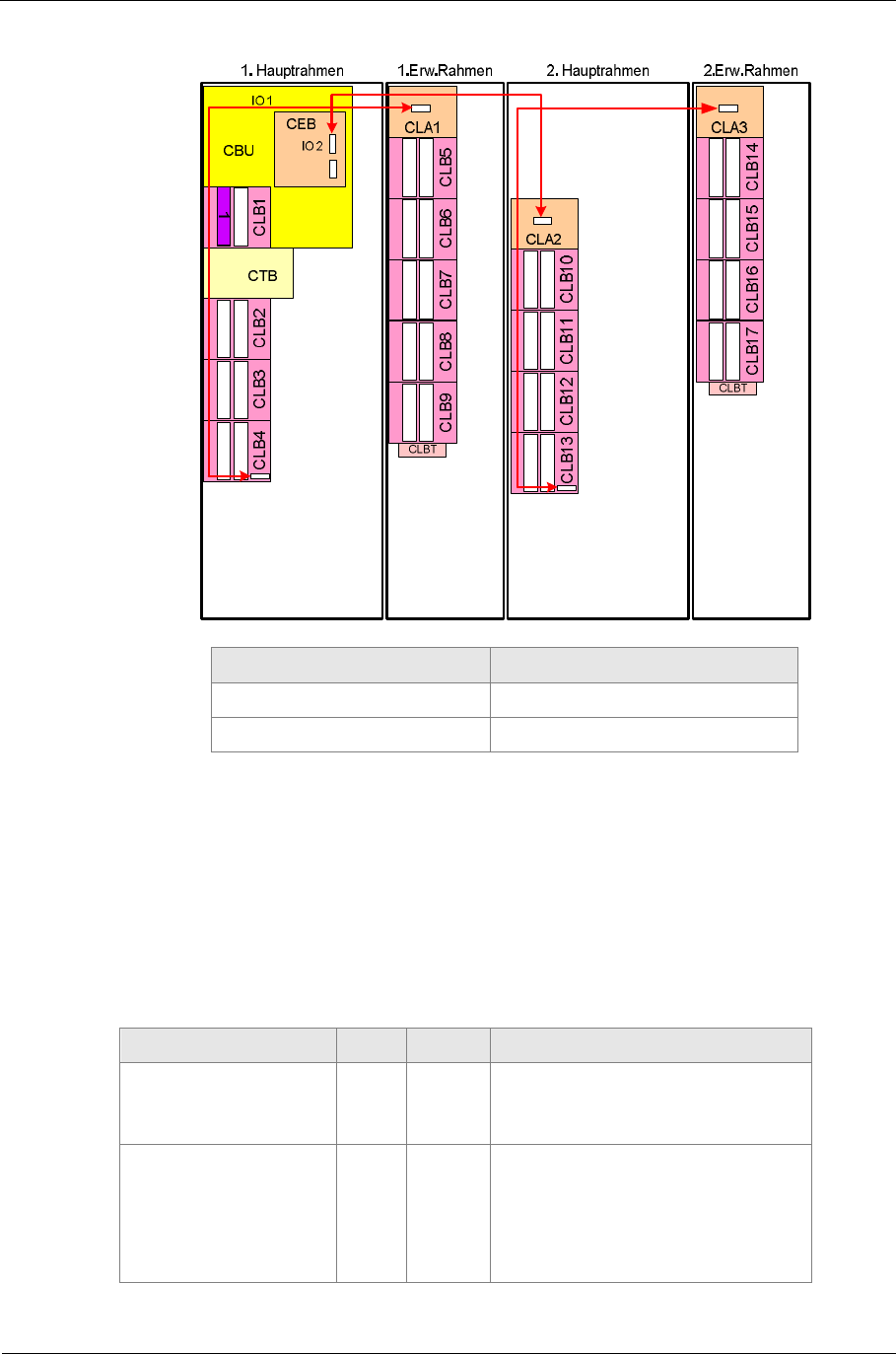
Sitraffic sX
Service manual controller technology 92
Components
Siemens AG V1.0 A001a / 2014-08-20
German English
Hauptrahmen main chassis
Erw.Rahmen Add-on chassis
Fig. 47: Maximum CLB assembly
2.19. IO module CIE//CIO
These 2 modules differ in their configuration and their function.
The module CIO is a minimal-configuration CIE module.
Function / module CIE CIO Number of I/Os
Internal I/Os X X 16 I/O Ports
(head connector)
External
Input/Output X X 8 IN (F buttons)
8 OUT (F confirmations)
base connector/terminal
block
Sitraffic sX
Service manual controller technology 93
Components
Siemens AG V1.0 A001a / 2014-08-20
Function / module CIE CIO Number of I/Os
XPort X 20 requests/
20 fault messages
(for Wimag/Video)
Tab. 45: CIE/CIO breakdown
2.19.1. Status LEDs
The message "Initial" appears during switch-on on for approx. 40 seconds
and should change to the status "Running" afterwards.
Status LED Fault LED SYS SW RUN
Initial Off On Off
Initial Fault On On Off
Running OFF Flash On
Running
Fault ON flash On
Tab. 46: CIE/CIO LED Information
2.19.2. Head connector (CIE/CIO)
At the head connector 16 units of 24 -V I/O ports are available.
The signals may be used only within the device.
Technical data:
■Input: +24V input, requires contact to 0V, (24 V/2 mA switching)
■Output: Selector switch to 0V, max. 30 V /50 mA
■The signal assignment of Pin 1-16 is identical to the head connector of
the BFD module of the C8x0/C9x0 controller.
Pin Signal
X2 Signal
X2 Pin
1GND IO1 2
3GND IO2 4

Sitraffic sX
Service manual controller technology 94
Components
Siemens AG V1.0 A001a / 2014-08-20
Pin Signal
X2 Signal
X2 Pin
5GND IO3 6
7GND IO4 8
9GND IO5 10
11 GND IO6 12
13 GND IO7 14
15 GND IO8 16
17 IO9 IO10 18
19 IO11 IO12 20
21 IO13 IO14 22
23 IO15 IO16 24
Tab. 47: CIE/CIO assignment for head connector
2.19.3. Base connector/terminal block (CIE/CIO)
At these, for the modules CIE and CIO, external 24- V DC buttons or
24 V DC confirmation devices can be connected.
For each module the following inputs and outputs are possible:
■8 Inputs (labeled "INx").
■8 Outputs (labeled "OUTx")
The operating power supply is to be fed individually for each module at the
points labeled "+PED" and "- PED". Since usually 2 pedestrian buttons and 2
pedestrian conformations are there, there are 2 terminals available for
each signal on the CLB. For the operating power supply for the sX-H an
additional 24 V DC power supply is needed.
2.19.3.1. Values of external input
Input switching is designed for connection of touch buttons or normal
buttons.
For each input 2 touch buttons/buttons can be connected.
The connected "+PED"/"-PED" power supply is voltage-monitored. If it fails
or is missing, all internal inputs will be set to occupy.
The return conductors of the outdoor system are connected to the
grounded 0V block at the bottom of the device.
Sitraffic sX
Service manual controller technology 95
Components
Siemens AG V1.0 A001a / 2014-08-20
Technical data for input
Function Value
Rating operating voltage +24 V ; +40 V; or
-24V /-40 V
Maximum voltage 20-48 V
Input Isolation 1500 V
Surge protection yes
Button pressed (Input=1) > 8 mA
Button not pressed (Input=0) < 6 mA
Maximum input current 10 mA
Short-circuit-resistant yes
Missing U_PED voltage < 16V Sets all inputs to 1
Terminals per input 2
Tab. 48: CIE/CIO input data
2.19.3.2. Values of external outputs
Output switching designed for the connection of confirmation devices.
For each output 2 confirmation devices can be connected.
Max 150mA together.
The 0V return conductors of the outdoor system are connected to the
grounded 0V block at the bottom of the device.
Technical data for output
Function Value
Rating operating voltage +24 V ; +40 V; or
-24 V /-40 V
Maximum voltage 20-48 V
Input Isolation 1500 V
Surge protection yes
Technology Plus side switching
Maximum continuous current 150 mA
Overcurrent shutdown 350 mA
Short-circuit-resistant yes
Reset status Output disabled
Terminals per input 2
Tab. 49: CIE/CIO Output data
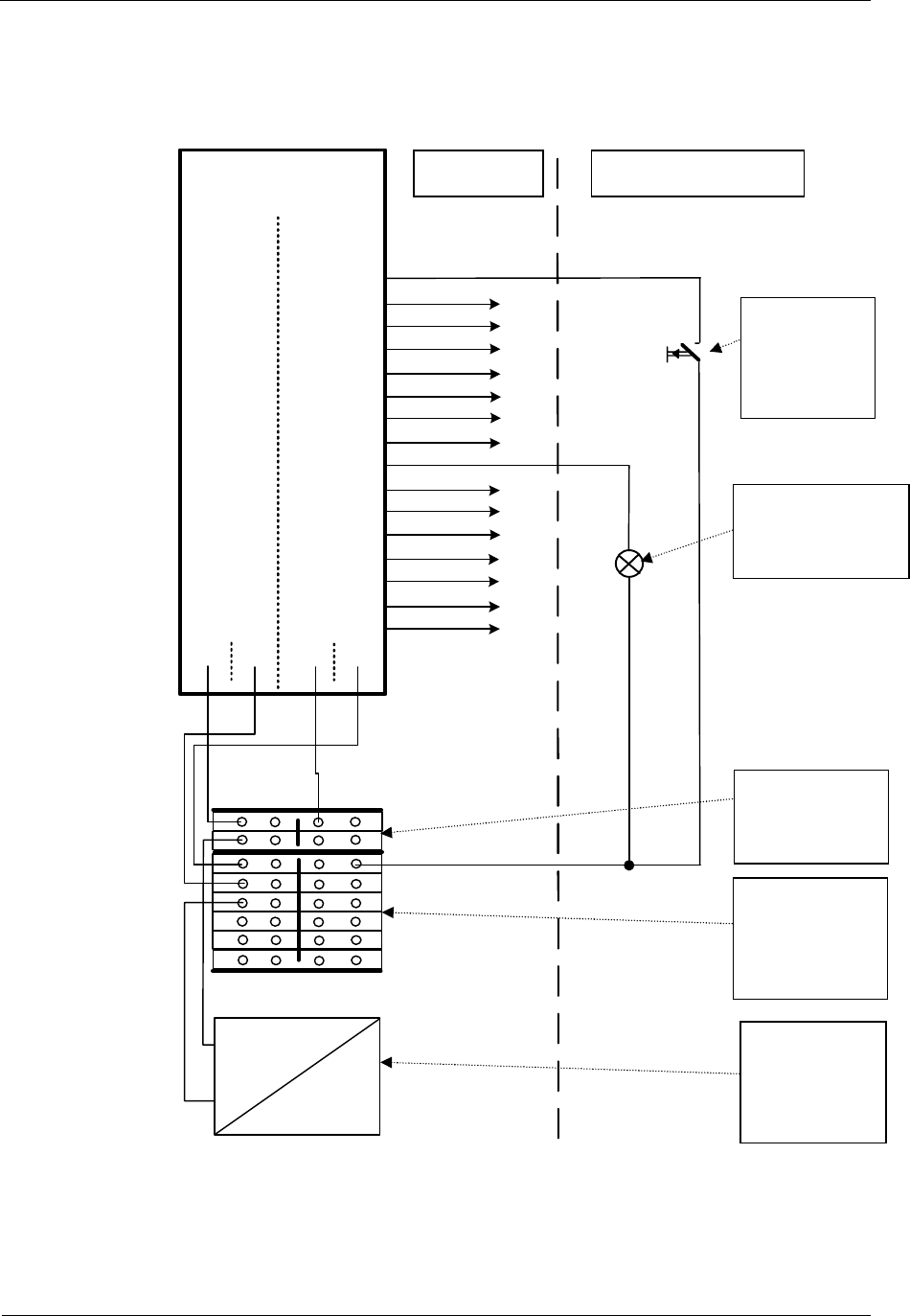
Sitraffic sX
Service manual controller technology 96
Components
Siemens AG V1.0 A001a / 2014-08-20
2.19.3.3. Connection button/confirmations with +24V
b1/a1
b2/a2
b7/a7
b8/a8
b5/a5
b6/a6
b3/a3
b4/a4
CIE/CIO
1
CLB
In1
b9/a9
b10/a10
b15/a15
b16/a16
b13/a13
b14/a14
b11/a11
b12/a12
In2
In3
In4
In5
In6
In7
In8
Out2
Out3
Out4
Out5
Out6
Out7
Out8
Out1
CIE/CIO
2
d1/c1
d2/c2
d7/c7
d8/c8
d5/c5
d6/c6
d3/c3
d4/c4
d15/c15
d16/c16
d13/c13
d14/c14
d11/c11
d12/c12
d9/c9
d10/c10
b17 a17
d17 c17
0V
+24V
PE
+24V 230V
+24V
0V
0V
Fig. 48: Confirmation devices and buttons with +24V
External system
Button/
sensor
button
Confirmation
device
24 V DC
power
supply unit
+24 V
distributor
sX
device
0V
distributor
block
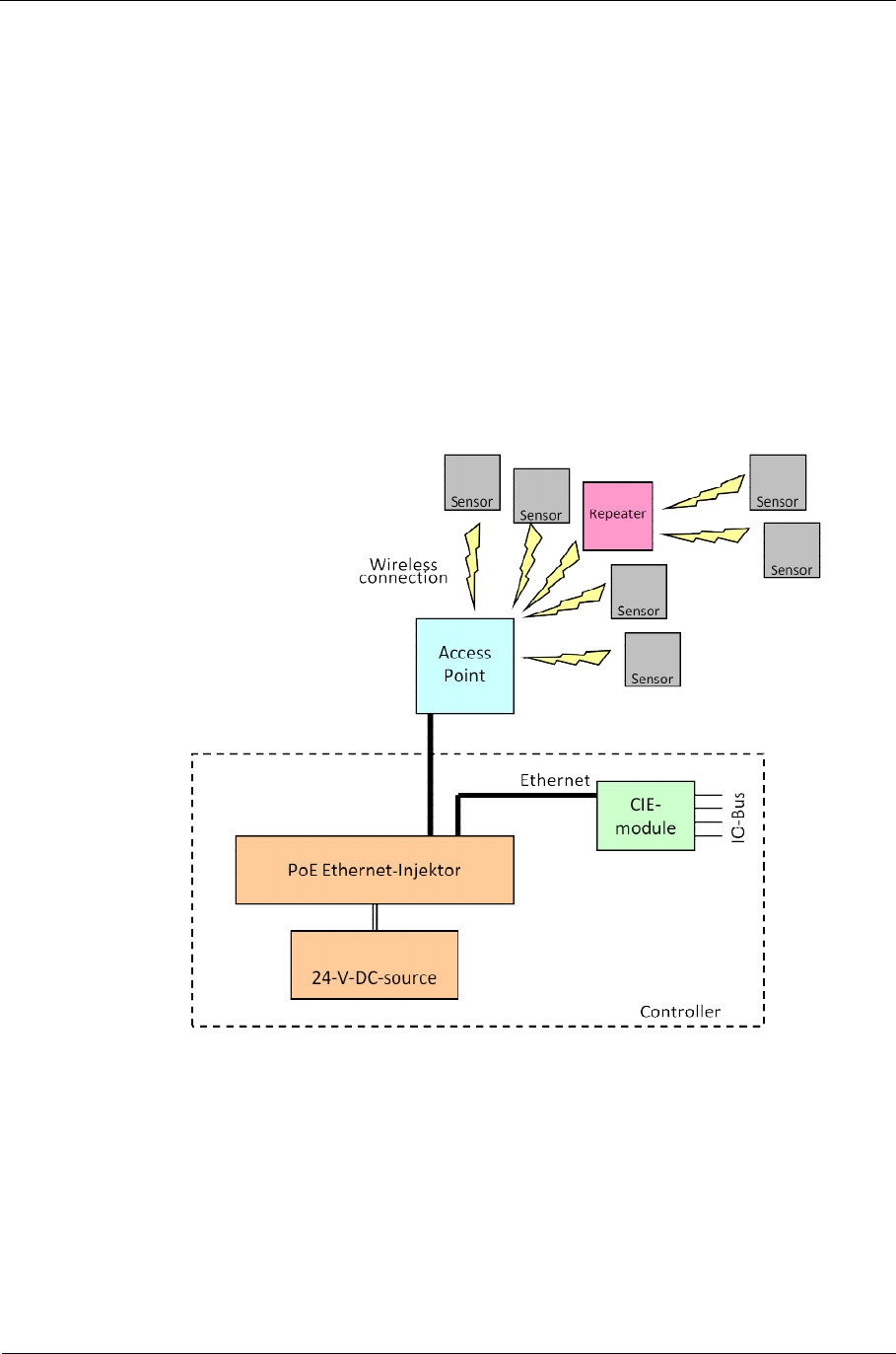
Sitraffic sX
Service manual controller technology 97
Components
Siemens AG V1.0 A001a / 2014-08-20
2.20. Wimag activation
For the activation of WIMAG detectors a CIE must be used. With an LAN
cable the connection is established from the PoE switch to the front-side
LAN connector of the module.
The associated WIMAG set is as follows:
C10 WIMAG basic set L24764-Z2000-A112
For description of the WIMAG function see BVD manual
For installation of the 24 V DC power supply see 2.28.
Fig. 49: WIMAG activation
Sitraffic sX
Service manual controller technology 98
Components
Siemens AG V1.0 A001a / 2014-08-20
2.21. Video detectors
For the connection of video detectors, adapter cards with the designation
DIB-E and DIB-P are being prepared.
2.21.1. DIB-E
The DIB-E (ZNX: DET-089-000151) is an interface module for the
connection of 6 video detectors (SIVICAM) to a Siemens intersection
controller. The DIB-E may be plugged into all SLD4 locations. In the sX
controller the data transmission is made via the serial I/O bus. Contrary to
the predecessor module DIB, the DIB-E has an interface for this serial IO bus
of the sX controller. Therefore the DIB cannot be used in an sX controller.
For function details on the SIVICAMs see "SIVICAM I-2 integrated video
detector user manual"
Note
A DIB cannot be plugged in to the sX controller because it has no IO bus
For required materials see Tab. 43.
2.21.1.1. Setting DIB-E address in the CLB
Here is to be proceeded exactly the same as with the CLB. See 2.15.
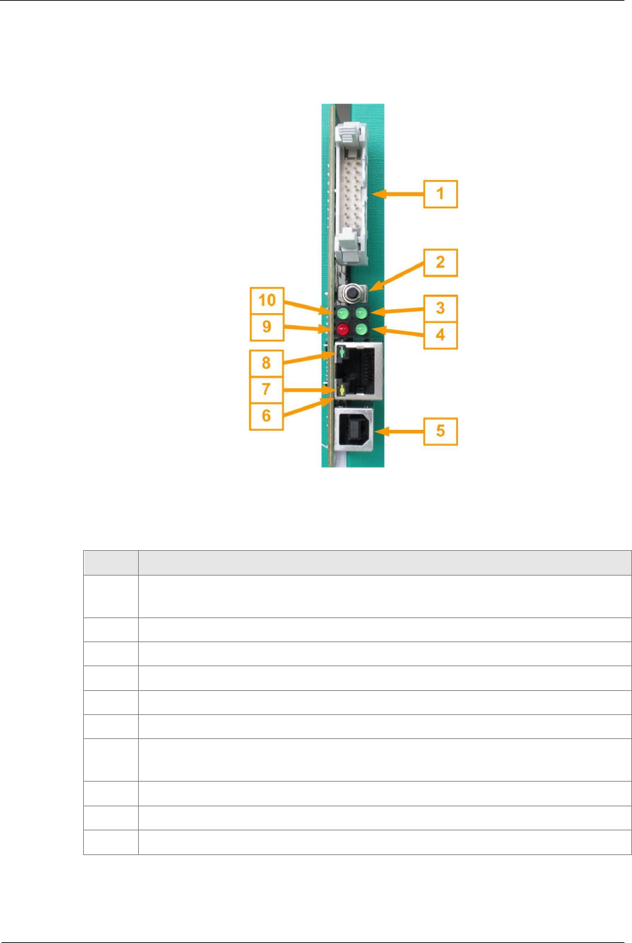
Sitraffic sX
Service manual controller technology 99
Components
Siemens AG V1.0 A001a / 2014-08-20
2.21.1.2. DIB-E Front
Fig. 50: DIB-E front side
No. Description
1Front connectors for the detection outputs 5 to 12,
is not used for operation in the sX controller
2Reset button
3COM LED1 flickers during communication with the SIVICAMs
4COM LED2 flickers during communication with the CBU via the IO bus
5USB device connector for the connection of a service PC
6Ethernet connector for the connection of a service PC (Patch cable)
7Ethernet LED is illuminated if a connection exists and
flickers if data is being transmitted.
8Ethernet LED is illuminated if a 100 Mbit/s connection exists
9ERRORLED flashes, if at least one SIVICAM is faulty
10 POWERLEDTab. 50: Description of DIB-E front side ( see Fig. 50

Sitraffic sX
Service manual controller technology 100
Components
Siemens AG V1.0 A001a / 2014-08-20
2.21.1.3. Head connector
In addition to the signals at the serial bus, the detection signals 5-12 are
present at the head connector. (Normally not used in sX).
The output switches:
■Max 35 V
■Max 40 mA
■Switches to 0 V
Here the assignment of the head connector:
Pin Signal
1GND
2Detection output 5
3GND
4Detection output 6
5GND
6Detection output 7
7GND
8Detection output 8
9GND
10 Detection output 9
11 GND
12 Detection output 10
13 GND
14 Detection output 11
15 GND
16 Detection output 12
Tab. 51: DIB-E front connector

Sitraffic sX
Service manual controller technology 101
Components
Siemens AG V1.0 A001a / 2014-08-20
2.21.1.4. USB port
In order to be able to use the DIB-E with the service PC, the "TrafiCam® PC
Tool" must be installed on it.
With the PC tool up to 8 zones on the roadway can be defined for each
SIVICAM. For each zone the SIVICAM supplies information for whether it is
assigned a vehicle.
The information concerning the up-to-48 zones of the CBU is requested via
the serial IO bus. Thus the assignment of the zones to the hardware
outputs of the DIB-E is done away with, which is needed for the other
intersection controllers.
For settings see "TrafiCam - 4TI ETH or 1TI" USER GUIDE
2.21.1.5. Ethernet port
The DIB-E can alternatively be operated by the "TrafiCam® PC Tool" via the
Ethernet port. The same commands as with the USB port are available. In
order to be able to use the Ethernet port, the IP address of the DIB-E must
be set via the USB port.
Usually the following addresses are used:
192.168.178.1 Setting with the service PC
255.255.255.0 Subnet mask
192.168.178.200 Setting with the DIB-P
2.21.1.6. LED description
LED DIB-E
is booting Normal operation
POWERLED is
illuminated is illuminated Operating voltage is okay
ERRORLED is
illuminated Off No fault
flashing Communication problems with
COM LED1 Off Off No communication with a
Communication with at least
COM LED2 Off Off No communication with the CLB
Communication with the CLB (CBU)
Tab. 52: DIB-E LED meaning
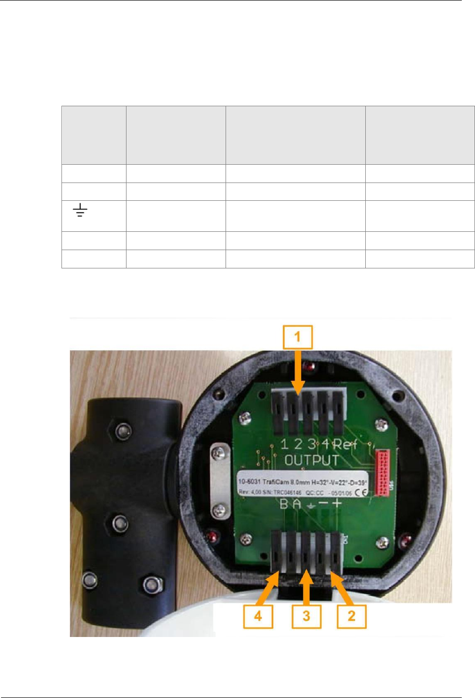
Sitraffic sX
Service manual controller technology 102
Components
Siemens AG V1.0 A001a / 2014-08-20
2.21.1.7. Connection of the SIVICAMs
For connection of the cameras protected ground cables (STP) with 5 wires
(0.5 qmm (AWG20)) are needed. The two wires for communication and for
the power supply must be twisted. The maximum cable length is 250 m.
SIVICAM
terminal Signal For connection points
see section: Designation of
the connection
points with sX in
this description
++ Power supply 2.21.1.9 24V
-- Power supply 2.21.1.9 0V
PE / shield 2.21.1.9 Ground
connection
ARS-485A 2.21.1.10 and 0 Vxa (x = 1 to 12)
BRS-485B 2.21.1.10 and 0 Vxb (x = 1 to 12)
Tab. 53: Assignment of the connecting cable for the SIVICAMs
Fig. 51: Connector terminals of the SIVICAM

Sitraffic sX
Service manual controller technology 103
Components
Siemens AG V1.0 A001a / 2014-08-20
No. Description
1Terminals for the detection outputs are not used with the sX controller
because the information is transmitted serially via the IO bus.
2Terminals for the power supply lines (twisted)
"+" is to be connected with 24V
"-" is to be connected with 0V.
3Terminal for the ground connection of the SIVICAM. The wire attached here
is to be grounded in the intersection controller.
4Terminals for the communication lines (twisted)
"A" is to be connected with a connection point Vxa for CLB and CTB
"B" is to be connected with connection points Vxb for CLB and CTB
Fig. 52: Description of the connection terminals of the SIVICAM
2.21.1.8. Topologies of the networks to be connected to the SIVICAMs
The cameras can be connected with the connection terminals of the DIB-E
by star networks or linear networks. A combination of star networks and
linear networks is also possible.
Definition of the possible network topologies for SIVICAMs
Star network Each SIVICAM is directly connected with
the DIB-E. Per SIVICAM a set of connection
terminals (RS485+, RS485, +24V, 0V and
PE) is needed.
Linear network One SIVICAM is directly connected with
the DIB-E, all other SIVICAMs are
connected in parallel in a line. For all
attached SIVICAMs only one set of
connection terminals is needed.
Combined star network / linear
network Individual SIVICAMs and lines are each
turned on at a set of connection terminals
of the DIB-E.
Tab. 54: Network topologies for SIVICAMs

Sitraffic sX
Service manual controller technology 104
Components
Siemens AG V1.0 A001a / 2014-08-20
Star network with 6 cameras Linear network with 6 cameras
Networks with a combination of star and linear network (max. 6 cameras)
Fig. 53: Possible topologies for the connection of the cameras
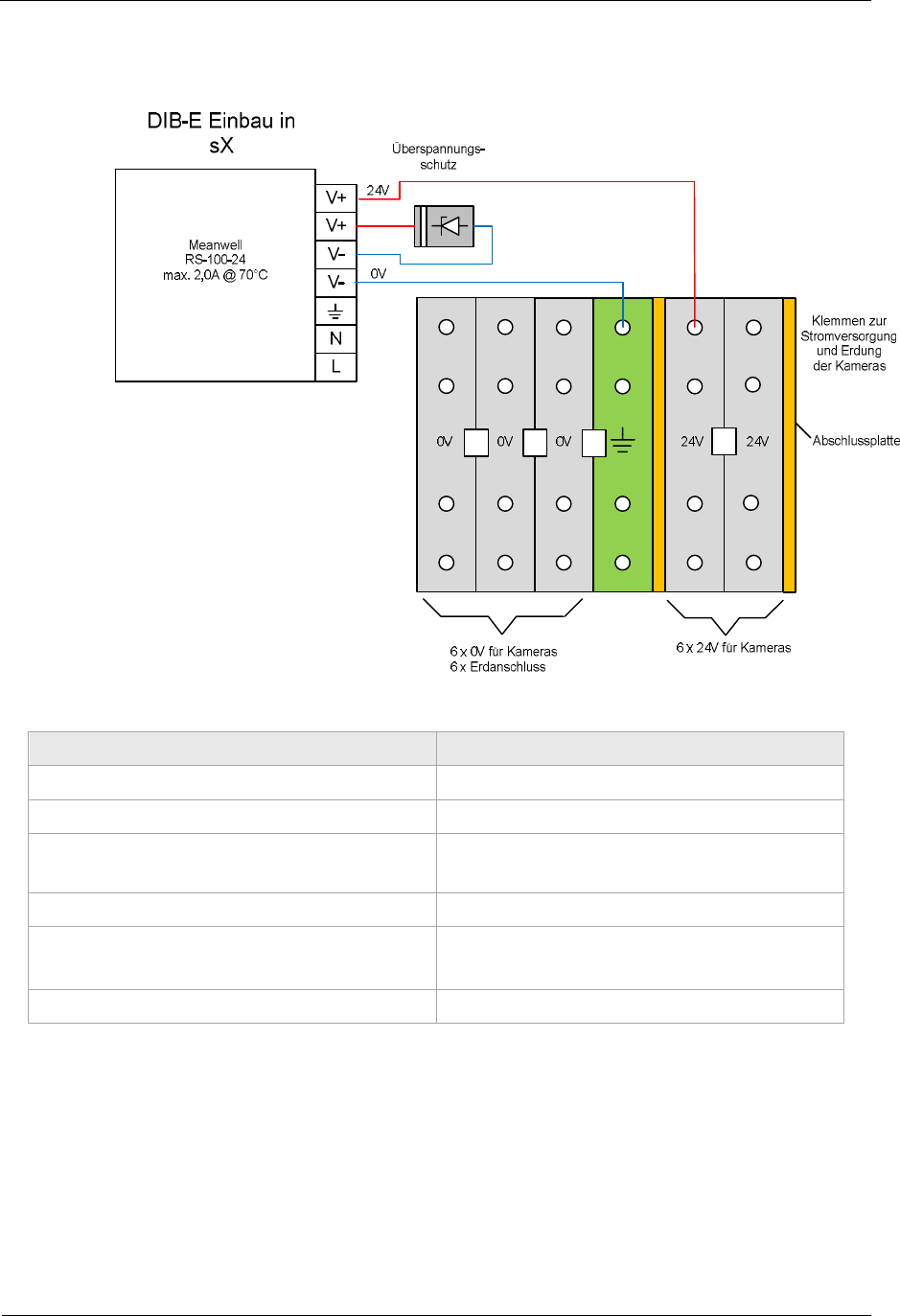
Sitraffic sX
Service manual controller technology 105
Components
Siemens AG V1.0 A001a / 2014-08-20
2.21.1.9. Power supply of the cameras
German English
DIB-E Einbau in sX DIB-E installation into sX
Überspannungsschutz Overvoltage protection
Klemmen zur Stromversorgung und
Erdung der Kameras Terminals for power supply and
grounding of the cameras
Abschlussplatte Termination board
6 x 0V für Kameras
6 x Erdanschluss 6 x 0V for cameras
6 x ground connection
6 x 24V für Kameras 6 x 24V for cameras
Fig. 54: DIP-E power supply for cameras
The two wires (0V and 24V) that lead to one camera must be twisted. The
shield of the ground cable is to be attached at the grounding connection
terminal of the camera and grounded in the intersection controller.
Per SIVICAM current consumption of 50mA at 24V is to be expected.
Because the auxiliary power supply can have up to 2.0A applied, up to 40
SIVICAMs can theoretically be operated.
Sitraffic sX
Service manual controller technology 106
Components
Siemens AG V1.0 A001a / 2014-08-20
2.21.1.10.DIB-E activation at the CLB
Up to 2 DIB-Es can be plugged in to the CLB module. For each DIB-E, 6
cameras can be connected. Connection point for each camera on the CLB
ist Vxa and Vxb.
the cameras V1 to V6 are attached to the DIB-E in the left installation
location X4. The cameras V7 to V12 are attached to the DIB-E in the right
installation location X5. Thus the following terminal assignment results.
X6 d c b a
1V8a V7a V2a V1a
2V8b V7b V2b V1b
3V10a V9a V4a V3a
4V10b V9b V4b V3b
5V12a V11a V6a V5a
6V12b V11b V6b V5b
7-- -- -- --
Up
to
17
-- -- -- --
Tab. 55: DIB-E connection assignment CLB
Since an RS485 bus is concerned here, the signal wires of the camera must
be twisted. A and B wires may not be mixed up.
Note on connecting the RS485 bus
If the 24V operating power supply of the SIVICAM is supplied, a voltage of 2
to 3V can be measured between the A wire and B wire while idle. Here, the A
wire leads the positive voltage.
If a DIB-E is plugged in, this voltage also can be measured between the
terminals Vxa and Vxb, where Vxa is more positive than Vxb.
The A wire of the camera is connected to Vxa and the B wire to Vxb.

Sitraffic sX
Service manual controller technology 107
Components
Siemens AG V1.0 A001a / 2014-08-20
2.21.1.11.DIB-E activation at the CBU
Here the following is to be considered:
The cameras are connected via terminal block X4 to the CTB.
For the DIB-E at the left installation location (X39) the CBU provides
connection options for only four cameras (V1x-V4x). If the cameras V6 and
V7 are to be attached, they are to be attached in parallel to connection
terminals for the cameras V1 to V4.
For the DIB-E at the right installation location (X40) of the CBU there are
connection options for six cameras (V7x-V12x) available.
Connection point for each camera on the CLB is Vxa and Vxb.
X4 c b a
1V1a V1b --
2V2a V2b --
3V3a V3b --
4V4a V4b --
5V7a V7b --
6V8a V8b --
7V9a V9b --
8V10a V10b --
9V11a V11b --
10 V12a V12b --
11 -- -- --
Up to
17 -- -- --
Tab. 56: DIB-E connection assignment CTB
For the connection of the cameras to the terminals the requirements of
section 2.21.1.10 apply.
2.21.1.12.Additional Information
SIVICAM I-2
user manual A001 / 2006-05-04
TrafiCam - 4TI ETH or 1TI
USER GUIDE 10-6090/91 (Flir, previously Traficon)

Sitraffic sX
Service manual controller technology 108
Components
Siemens AG V1.0 A001a / 2014-08-20
2.22. 230 V pedestrian request / pedestrian confirmation CIAC/CIAB
For the connection of AC confirmations/requests the CIAB backplane
(S24734-A897-A1) and the CIAC module (S24734-A896-A1) is needed. The
CIAB module has the format of a CLB module and is built in to the CLB
housing. Thus it can be installed in all CLB locations. The same housing as
for the CLB is used. Up to 2 CIAC modules can be plugged into the CIAB
backplane. For each CIAC module, 6 inputs and 6 outputs are available.
(There are thus 12 inputs and 12 outputs possible per CIAB).
For this the following is required:
■1 x CIAB bracket set /C10 L24730-E810-A40
■1x CIAB Backplane /C10 L24730-E811-A200
■CIAC assembly set 117/230 V /C10 L24730-E811-A21
■1-2x CIAC C10 I/O AC 24V/230 V /C10 S24734-A896-A1
The CIAC/CIAB module is designed for the following voltages and currents:
Range Minimal
Voltage
in V AC
Maximum
Voltage
in V AC
Operating
voltage
in V AC
Maxi-
mum
Current
In A
Max.
number
of
sensor
buttons
INPUT
Sensor
button/
Button
80 265 117
230 0,05 2
OUTPUT
(Confir
mation)
18 265 24
40
117
230
0,3
Tab. 57: Technical limit values
Note:
■The maximum connectable cable length is 250 m.
■It is not possible with this module to connect DC buttons/touch buttons
and DC confirmation devices.
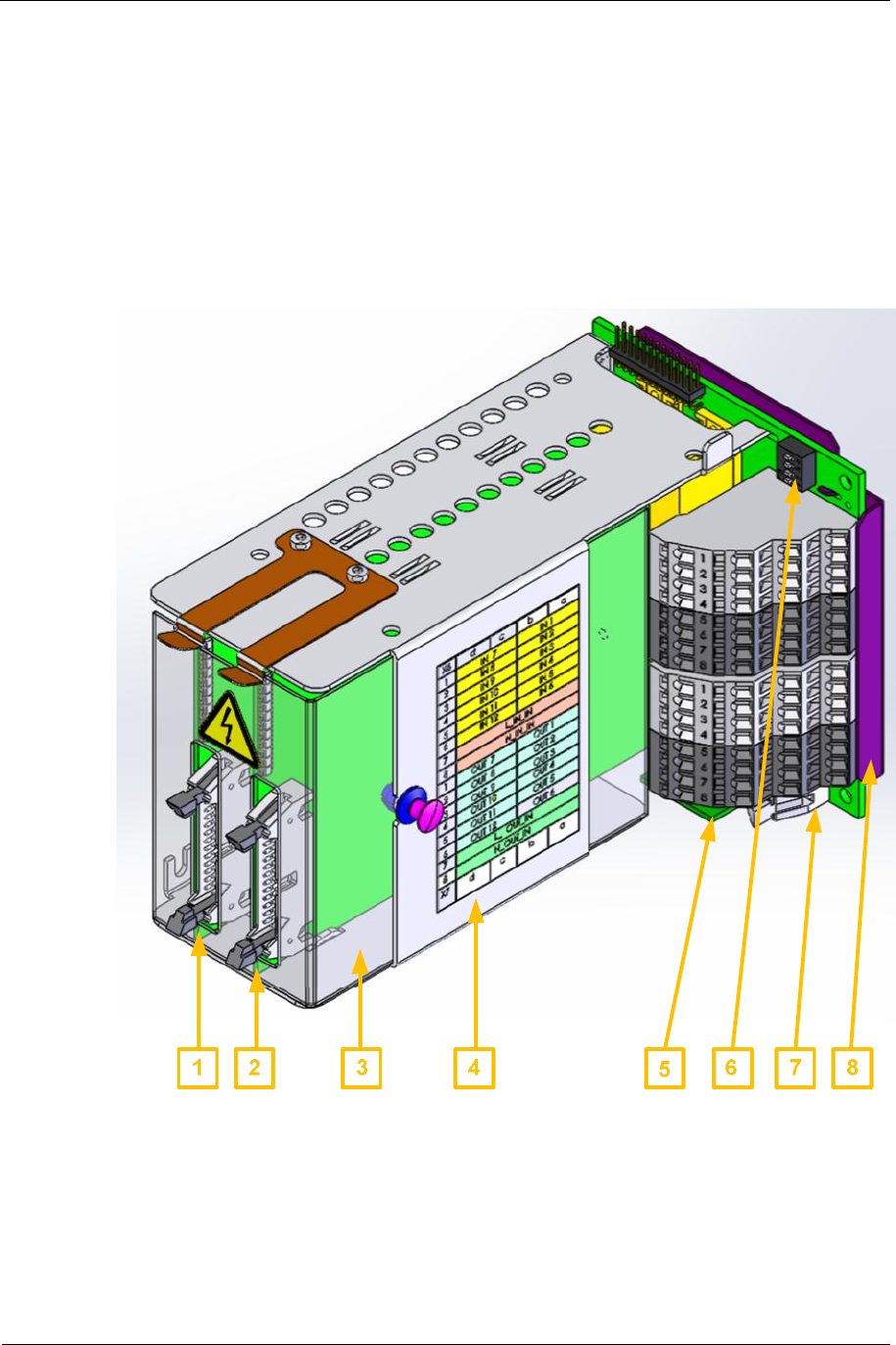
Sitraffic sX
Service manual controller technology 109
Components
Siemens AG V1.0 A001a / 2014-08-20
■For special cases with more than 0.3 A AC confirmation current, the
BFU module (S24734-A621-A1) is to be installed in the in the special
adapter CUA (L24730-E815-A1).
■The inputs and output can be operated with different voltages. But the
inputs of module 1 and module 2 have the same voltage within a CIAB.
Also the outputs of module 1 and module 2 have the same voltage
within a CIAB. (Common power supply).
Fig. 55: CIAB/CIAC structure

Sitraffic sX
Service manual controller technology 110
Components
Siemens AG V1.0 A001a / 2014-08-20
No. Description
1CIAC 1
2 CIAC2
3Contact protection CIAC (transparent)
4CLB housing with inscription
5CLBT module
6 Address switch CIAB
7CIAB module
8Contact protection CIAB
Tab. 58: Structure of CIAB/CIAC
2.22.1. Setting CIAB address
Here is to be proceeded exactly the same as with the CLB. See 2.15.
2.22.2. Structure of CIAB
Since the terminal assignment cannot be represented on the CIAB, a sticker
with the terminal assignment is affixed to the housing. The sticker is
included in the CIAB assembly set. In the CIAB the items a/b and c/d,
respectively, are connected in parallel (except Lxx and Nxx) in order to
have 2 terminals when activating buttons and confirmations.
the left plug-in location (X4) goes to the terminals a/b.
The right plug-in location (X5) goes to the terminals c/d.
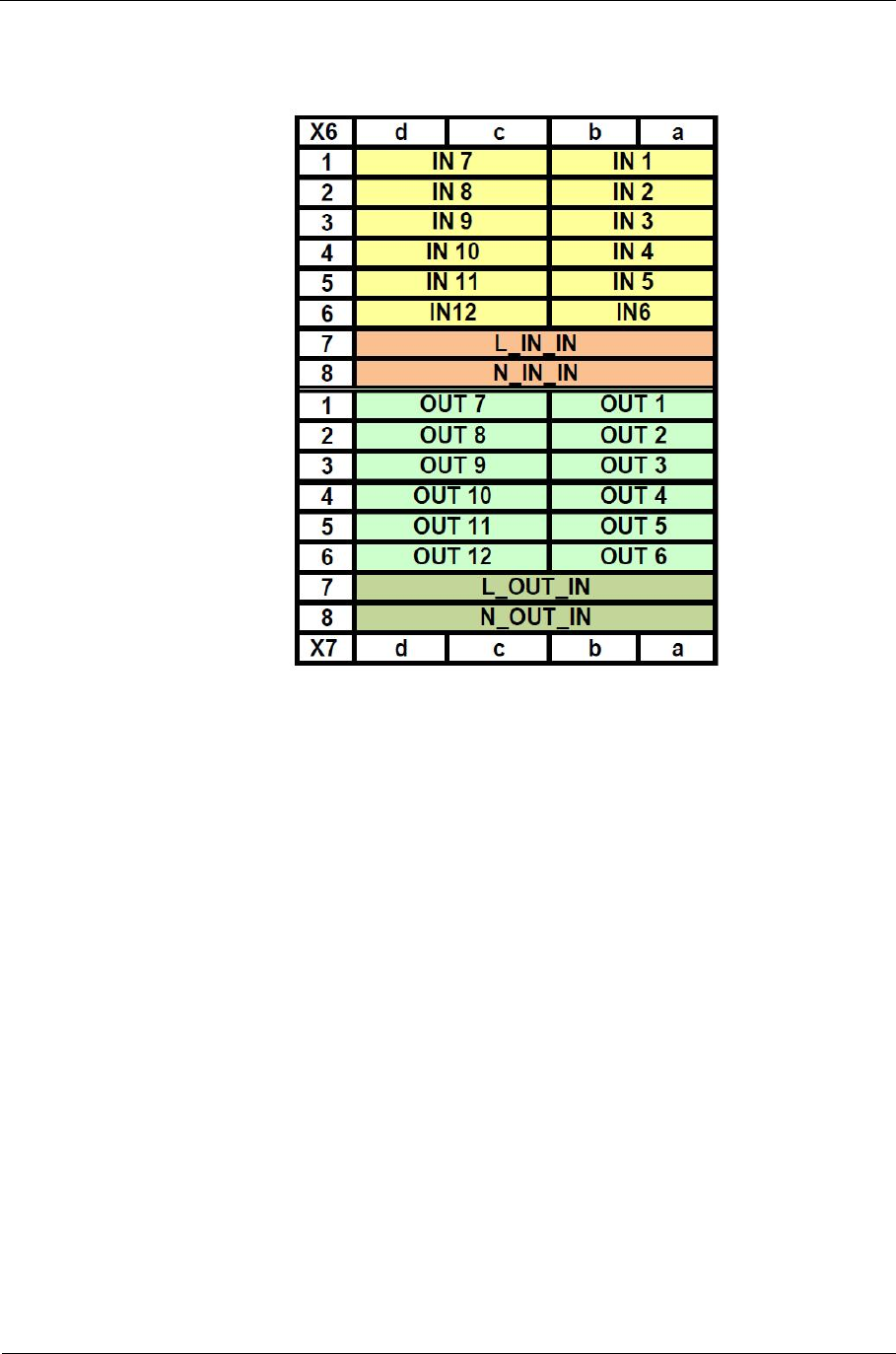
Sitraffic sX
Service manual controller technology 111
Components
Siemens AG V1.0 A001a / 2014-08-20
2.22.3. Terminal assignment for CIAB
Tab. 59: Terminal inscription CIAB/CIAC
2.22.4. CIAC breakdown
The CIAC module is attached to the serial I/O bus. For the correct
assignment, therefore, the setting of the address is necessary in the CIAB.
The CIAC consists of 3 functional parts:
■16 non-isolated head connector I/Os for internal applications.
■6 isolated AC inputs (only accessible on the CIAB).
■6 isolated AC outputs. (Only accessible at the CIAB).
Each external output and the input voltage are protected with a 1.0A fuse
(F1-F7).
All fuses are monitored and a failure is reported.
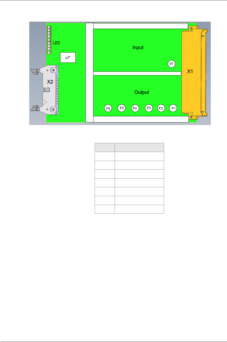
Sitraffic sX
Service manual controller technology 112
Components
Siemens AG V1.0 A001a / 2014-08-20
Set replacement fuses 1.0AT/230 V with 20 units L24730-A899-A3
Fig. 56: CIAC breakdown
No. Description
F1 Fuse Out1
F2 Fuse Out2
F3 Fuse Out3
F4 Fuse Out4
F5 Fuse Out5
F6 Fuse Out6
F7 Fuse IN
Tab. 60: CIAC Fuses
2.22.5. CIAC LED meaning
The LEDs are arranged from top to bottom in the following sequence at the
front side of the module:
IN voltage
OUT voltage
IN1/OUT1
IN2/OUT2
IN3/OUT3
IN4/OUT4
IN5/OUT5
IN6/OUT6
Sitraffic sX
Service manual controller technology 113
Components
Siemens AG V1.0 A001a / 2014-08-20
FAULT
SYS Run
SW
The LEDs have the color green and to show the presence of the IN voltage
and the OUT voltage.
LED function LED
ON LED
OFF
IN voltage INPUT voltage
present INPUT voltage missing
or F7 defective
OUT voltage OUTPUT voltage
present OUTPUT voltage
missing
Tab. 61: CIAC LED Function1
All input (INx) and output signals (OUTX) are represented on 2-colored
LEDs.
The indicator information then looks as follows:
INx OUTx LED color
OFF OFF Off
ON OFF RED
OFF ON GREEN
ON ON YELLOW
Tab. 62: CIAC LED Function2
The LEDs FAULT, SYS-RUN and SW have the same meaning as on the CIE.
See 2.19.1
2.22.6. CIAC head connector (X2)
The CIAC head connector has the same technical data and assignment as
the CIE head connector. See 2.19.2.
2.22.7. External input
2 touch buttons or 2 buttons can be connected at each external input. The
connection points are accessible only in the CIAB.
Technical data for INPUT
Sitraffic sX
Service manual controller technology 114
Components
Siemens AG V1.0 A001a / 2014-08-20
Function Value
Rating operating voltage 115V AC
230 V AC
Maximum voltage 80-265 V AC
Input Isolation 3000 V AC
Surge protection Yes, integrated
Button pressed
(Input=1) U_INx < 9 V AC
Button not pressed
(Input=0) U_INx > 14 V AC
Maximum input current 50 mA AC
Short-circuit-resistant yes
Missing L_IN voltage
< 16V Sets all inputs to 1
Terminals per input 2
Tab. 63: CIAC input data
2.22.8. Output
At each output 1-2 confirmation devices can be attached.
The confirmation devices are permanently connected to N_OUT and
receive the switched L_OUT voltage.
The holding current of the triac may be up to 15mA. Each triac is protected
with a 1.0A fuse.
Technical data for OUTPUT
Function Value
Rating operating voltage 24 V, 40 V, 115 V, 230 V
Maximum voltage 18-265 V AC
Input Isolation 3000 V AC
Surge protection Yes, integrated
Technology Triac switch
Maximum continuous current 0.3 A
Fuse 1.0 A
Minimum current 15 mA
Reset status Output disabled
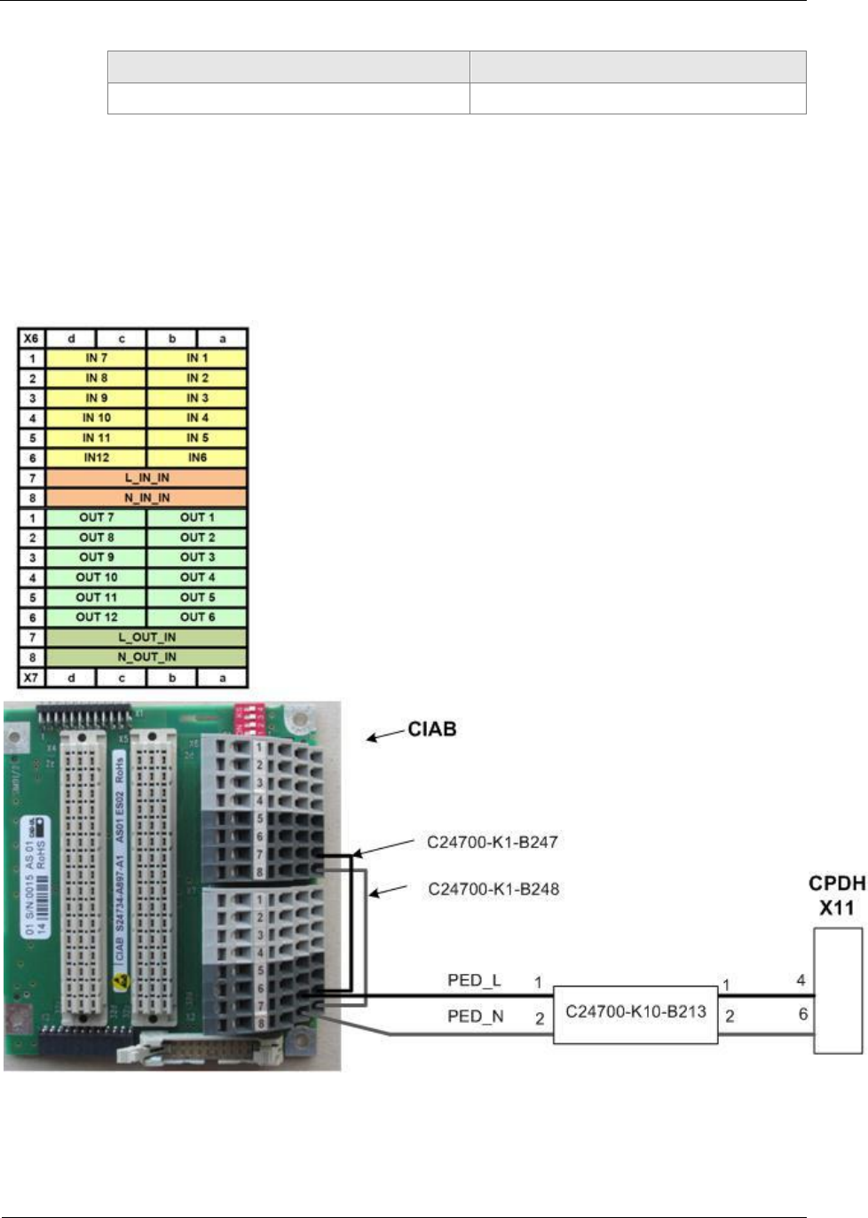
Sitraffic sX
Service manual controller technology 115
Components
Siemens AG V1.0 A001a / 2014-08-20
Function Value
Terminals for each output 2
Tab. 64: CIAC output data
2.22.9. CIAB activation internally 230 V
For the 230-V connection the PED_L and PED_N voltage is removed from
the CPDH at connector X11.
Fig. 57: CIAB activation, internal
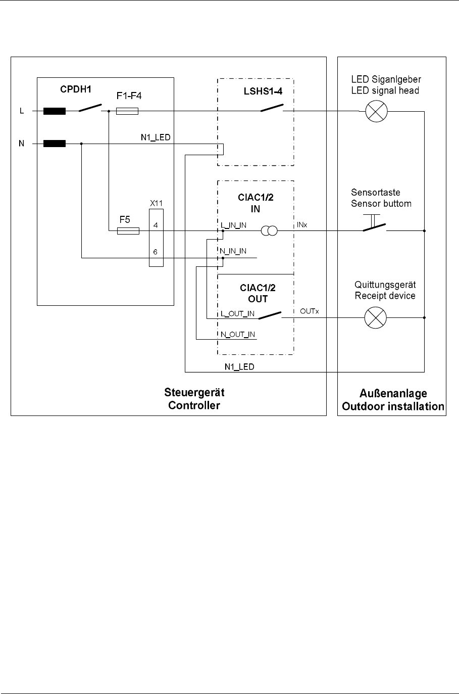
Sitraffic sX
Service manual controller technology 116
Components
Siemens AG V1.0 A001a / 2014-08-20
2.22.10. Activation button for confirmation devices 230 V
Fig. 58: Connection button/confirmations

Sitraffic sX
Service manual controller technology 117
Components
Siemens AG V1.0 A001a / 2014-08-20
2.22.11. CIAB connection, internal for signal heads for the visually impaired
For the activation of the signal heads for the visually impaired, the
following terminal set is also needed:
SX CIAB terminal set L24730-E811-A4
The terminals for the operating power supply for the signal heads for the
visually impaired are available with this terminal set. (PED_L to orange, and
PED_N to red).
The activation looks as follows in this case:
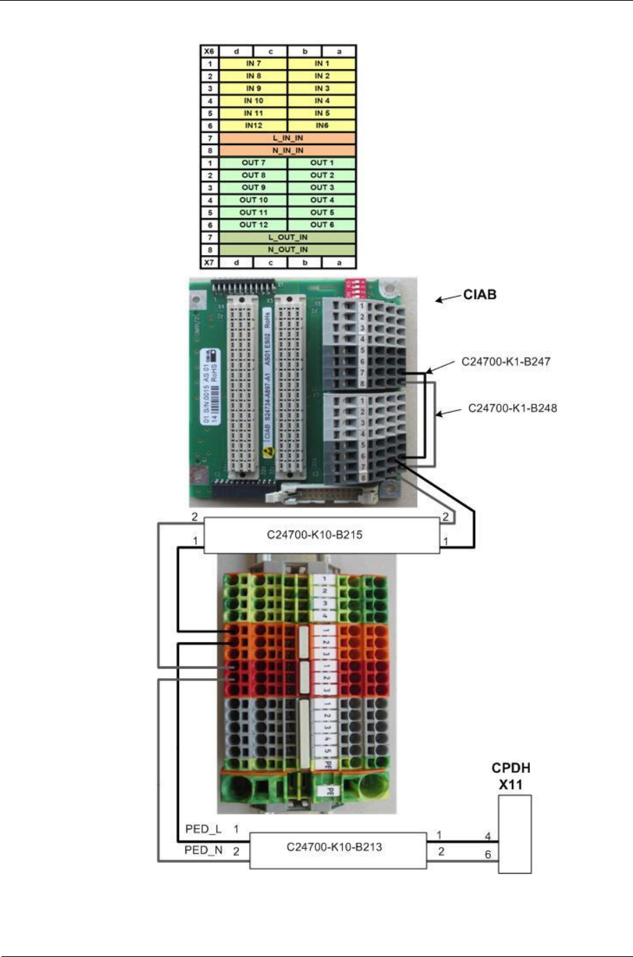
Sitraffic sX
Service manual controller technology 118
Components
Siemens AG V1.0 A001a / 2014-08-20
Fig. 59: Activation of signal heads for visually impaired, internal
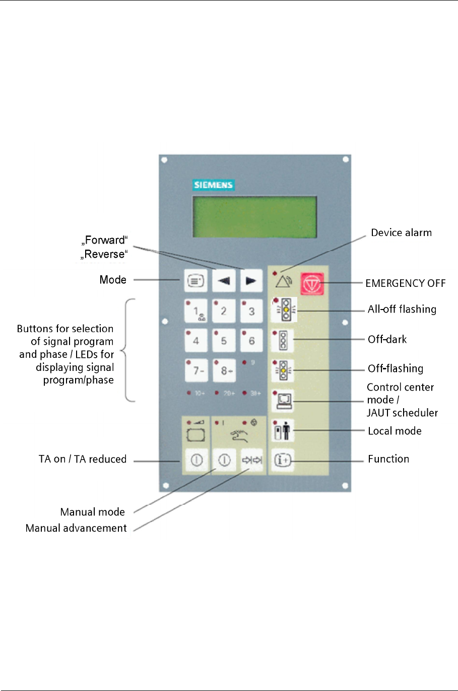
Sitraffic sX
Service manual controller technology 119
Components
Siemens AG V1.0 A001a / 2014-08-20
2.23. BAZ operating unit
A display and command unit (BAZ2, L24734-F655-A5) is provided on all
devices as standard, meeting DIN 50556 functionality requirements. The
control element has a membrane keypad with an LED display for each key
and for additional function displays. Further information is indicated by an
illuminated LCD display with 4x20 characters.
Fig. 60: BAZ
For description of the function see manual 1g section 5.1.2
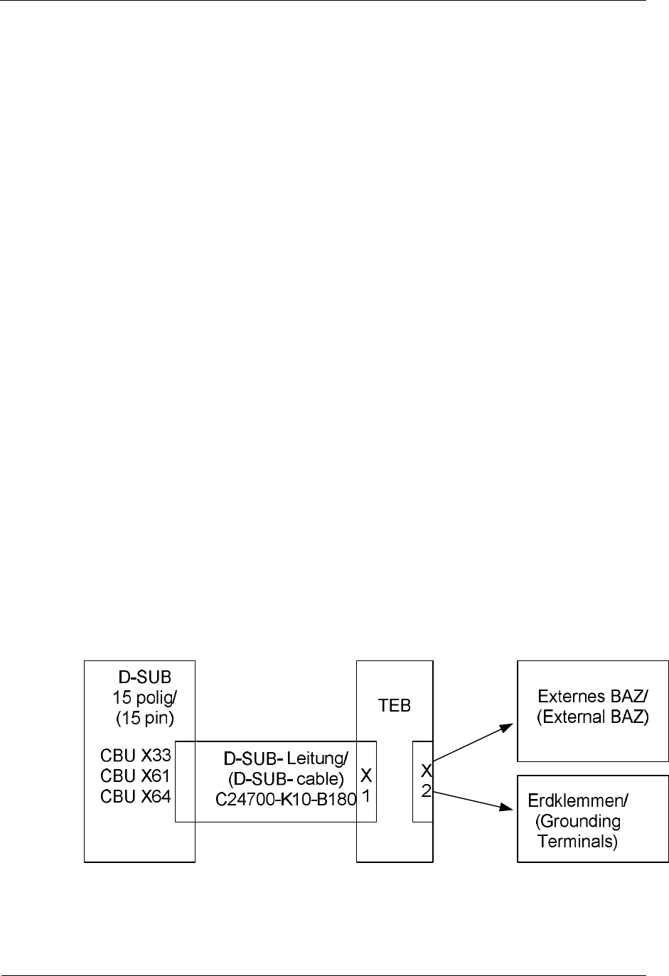
Sitraffic sX
Service manual controller technology 120
Components
Siemens AG V1.0 A001a / 2014-08-20
2.23.1. BAZ installation, internal
The internal command unit is accessible via a separately lockable door from
the outside. Installation is possible in the device door as well as in the left-
side or right-side parts. This means that the basic version of each device
has a display for all important information.
The BAZ is connected to the 15-pin X33 connector of the CBU as a
standard. With the cable 24-V power supply, serial data transmission and
emergency off button are connected to their intended interfaces on the
CBU.
The required materials for this are:
BAZ 2 Module Cxx0 L24734-F655-A5
CBU-BAZ /C10 cable C24700-K10-B180
Accessory kit for BAZ 2 module /CXX C24734-A16-B999
2.23.2. External BAZ
Up to 3 BAZ interfaces are possible in the sX controller. These are:
CBU_X33 or CEB_X61 or CEB_X64.
For activating the external BAZs a TEB module is required in the sX
controller for electrical isolation. The installation set additionally includes:
C10 BAZ externally prepared L24730-E810-A35.
The CEB module must be ordered separately.
Fig. 61: Block diagram BAZ external
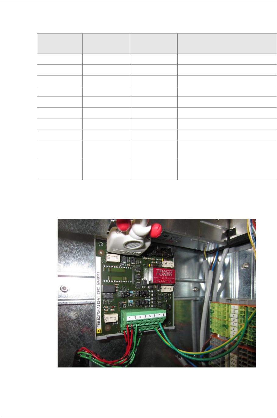
Sitraffic sX
Service manual controller technology 121
Components
Siemens AG V1.0 A001a / 2014-08-20
TEB
Terminal BAZ
Connector Signal
name Comment
X2.a1 X1.7 24V_TA1 1)
X2.b1 X1.7 24V_TA1 1)
X2.a2 X1.1 0V_TA1 1)
X2.b2 X1.2 0V_TA1 1)
X2.a3 X1.5 0V_TA2 0V return from the BAZ
X2.b3 X1.9 FLSMST.L EMERGENCY OFF
X2.a4 X1.8 SRTA1.A Line A
X2.a5 X1.3 SRTA1.B Line B
X2.a8 --- PE PE for overvoltage conductor
èPE rail in the controller
X2.b8 ---- PE Grounding of 0V_TA1
èPE rail in the controller
Tab. 65: Activation of BAZ external
1) Wires connected pairwise in parallel because of voltage drop on the
power supply.
Fig. 62: Installation TEB_BAZ_external
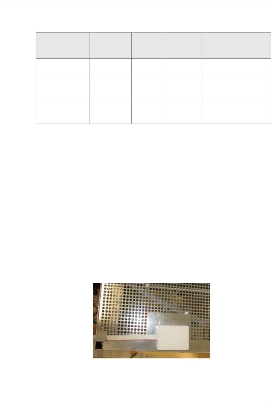
Sitraffic sX
Service manual controller technology 122
Components
Siemens AG V1.0 A001a / 2014-08-20
2.24. Alternative command device
Signal
CBU Signal
direction
CBU
Imax
/ mA Terminal
X4
CTB
Application
24V_EXT_Out Output 150 10a Power supply
command device
RCD Input -- 11a Emergency off for
LED switch
voltage
0V -- -- 14b, c 0V device
0V -- -- 14b, c 0V device
Tab. 66: Connection terminals for alternative command device.
If another command device is used that cannot be operated for the BAZ at
the serial interface of the CBU, the connection of the operating power
supply and of the emergency off button may take place on terminal block
X4 of the CTB. The associated signals are: "24V_EXT" and "RCD_L".
2.25. CCU GPS internal
For determining the time a GPS receiver (CCU, V24734-Z894-A1) is
connectable. Thus world-wide receipt of time is possible. This is built in to
the exterior of the metal chassis in the cabinet. The CCU has a magnet on
the back side and is to be affixed to the non-perforated surface of the
chassis. The line is attached for the CBU_X31. After switching on it takes
approx. 2 minutes for the GPS time to be available.
Fig. 63: CCU assembly
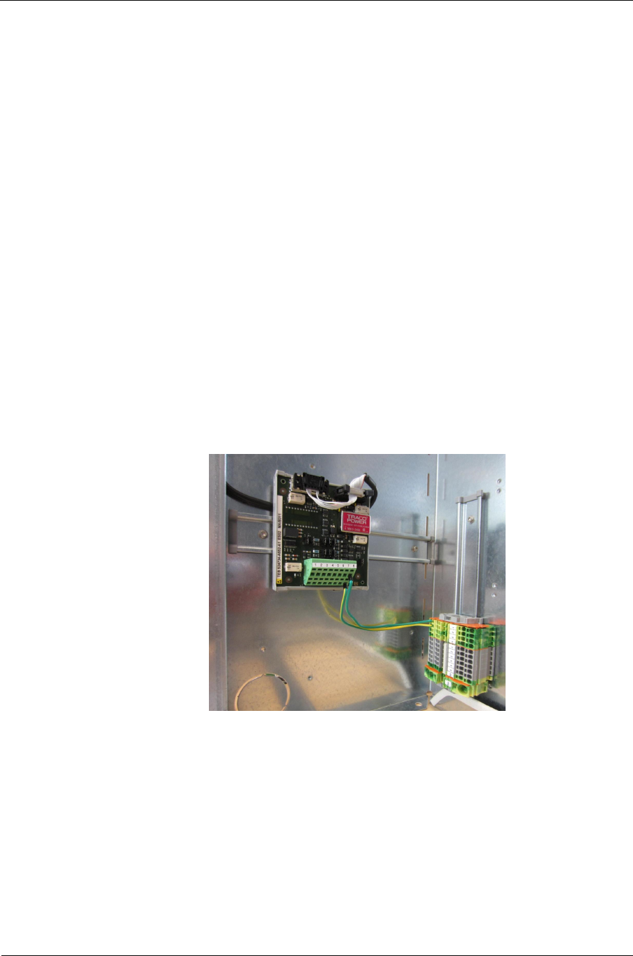
Sitraffic sX
Service manual controller technology 123
Components
Siemens AG V1.0 A001a / 2014-08-20
2.26. CCUE GPS External
If at the place of assembly no GPS reception is possible (e.g. under bridges,
in buildings, under large trees) an external GPS receiver (CCUE, V24734-
Z895-A1) can be used. This is installed on a pole. In the sX controller a
driver module TEB must be installed for this.
The set for the installation in the sX controller is called:
CCUE prepared /C10 L24730-E810-A61
Upon delivery of the TEB all jumpers are in the position 2-3. For correct
operation of the TEB with the CCUE, only jumper X4 is to be changed to 1-2
(bottom). The TEB is to be installed at the bottom left onto the horizontal
top-hat rail in the main chassis.
The CCUE set for the external pole assembly including fasteners is called:
CCUE Set GPS ext. /C10 L24730-E810-A60
(The same housing and attachment are used as for the DCF receiver).
Fig. 64: CCUE_TEB installation
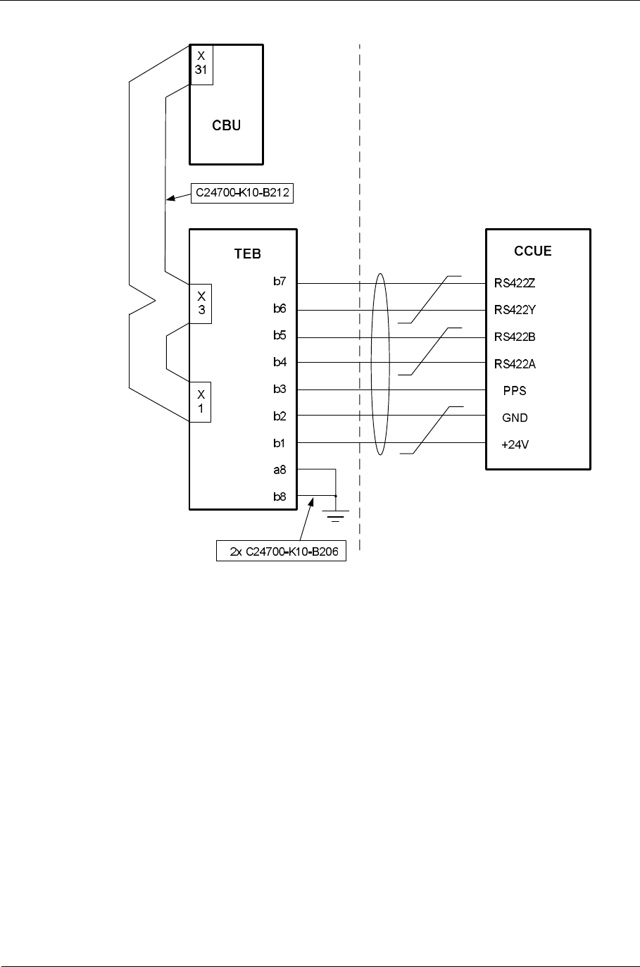
Sitraffic sX
Service manual controller technology 124
Components
Siemens AG V1.0 A001a / 2014-08-20
Fig. 65: CCUE_TEB activation
2.27. PT preference (AFD)
This function is only implemented and described in a later stage.
2.28. Supplementary power supply 24V DC
For this function there is the following set:
C10 power supply Set 24 V DC 48 W L24730-E814-A2
These sets include the power supply unit and the mounting material
(without mounting brackets). Only one DC power supply can be installed
on the mounting bracket. The mounting bracket is the size of a CLB module
and is to be installed on the last CLB location. (On the right side of the
mounting bracket the AC power supply can be installed).
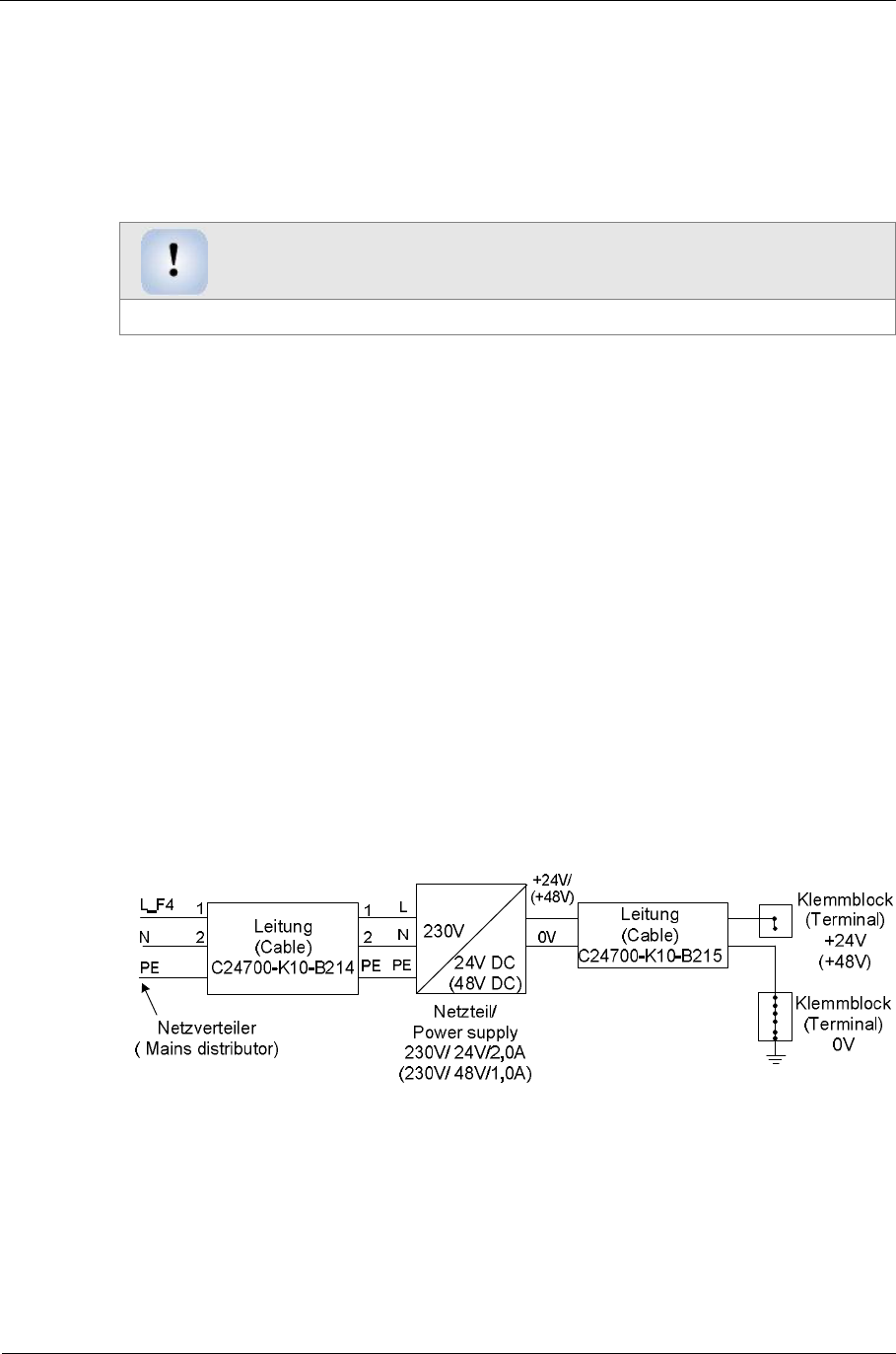
Sitraffic sX
Service manual controller technology 125
Components
Siemens AG V1.0 A001a / 2014-08-20
The mounting bracket
Mounting bracket power supply set /C10 L24730-E814-A14 during
retrofitting: must also be ordered, unless the
power supply Set 24 V AC 60 VA L24730-E814-A1 is already built in.
Note
The maximum permitted load of the RS100-24 is 48 W (2.0 A)
The replacement part number for the 24 V power supply is: V24069-
Z8043-A1.
Activation:
The 0V block in the device already in place is to be used and is not included
in the set.
For the plus voltage there are 2 terminals included in the set.
The auxiliary power supply is to be installed onto the mounting bracket.
Standard installation location is the lowest CLB location in the main
chassis.
See Fig. 5, no. 2
The mounting bracket can also be mounted on other CLB installation
locations on site. Then the line lengths are to be examined and if necessary
have the lines replaced by longer lines.
It must however always be the last installation location in the row because
no CLB/CIAB modules can be attached at the mounting bracket.
Fig. 66: Activation of DC power supply
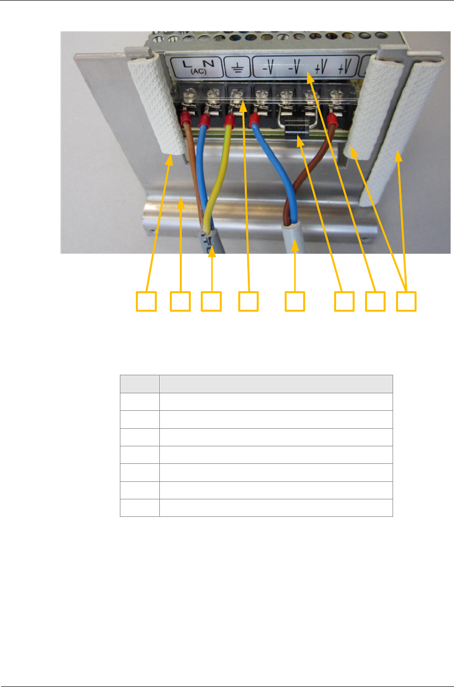
Sitraffic sX
Service manual controller technology 126
Components
Siemens AG V1.0 A001a / 2014-08-20
1 165432 7
Fig. 67: Mounting power supply
No. Description
1Edge protection
2Power supply retainer bracket
3C24700-K10-B214 line
4Contact protection RS100 (transparent)
5C24700-K10-B215 line
6Overvoltage protection diode (1)
7RS100
Tab. 67: Mounting parts for power supply
(1) The connection of the protection diode marked with the white ring is to
be connected with the positive voltage of the power supply.
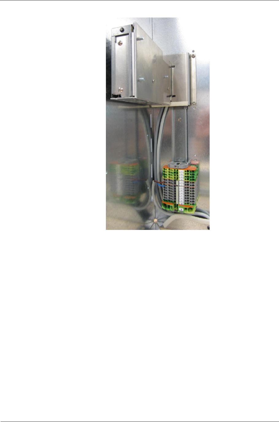
Sitraffic sX
Service manual controller technology 127
Components
Siemens AG V1.0 A001a / 2014-08-20
Fig. 68: Installation of the DC power supply
2.29. Supplementary power supply 24V AC
For this function there is the following set:
C10 power supply Set 24 V AC 60 VA L24730-E814-A1
This set is needed for 24 V AC confirmations, for example. The transformer
is installed onto the right side of the mounting bracket. The connecting
leads are so long that they reach all the way to the power distributor.
The maximum permitted load of the transformer is 60VA (2.5 A).)
Replacement part number for 24 V AC transformer is: V24068-Z5050-A1.
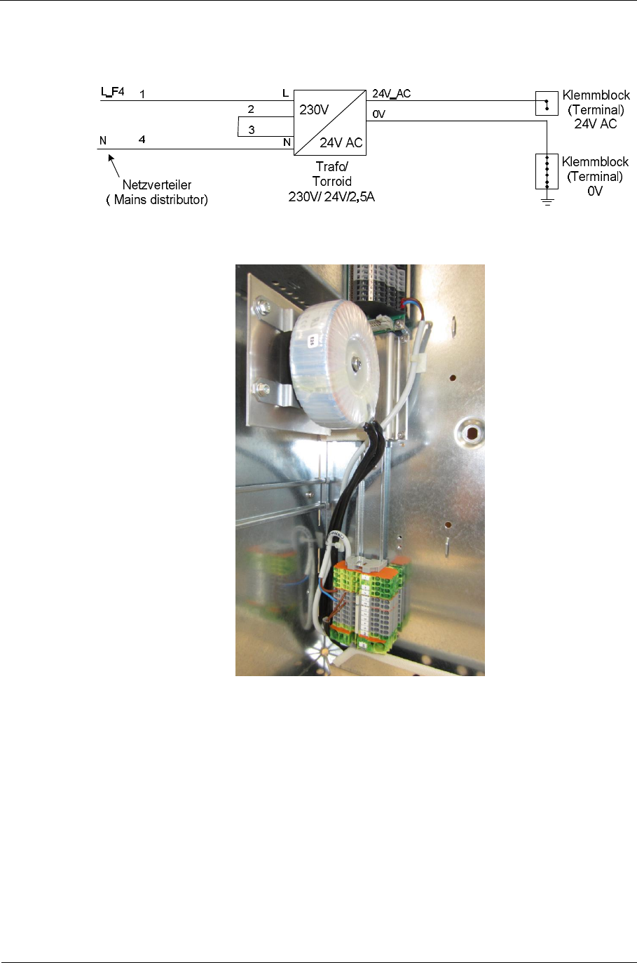
Sitraffic sX
Service manual controller technology 128
Components
Siemens AG V1.0 A001a / 2014-08-20
2.29.1. Activation
Fig. 69: Activation of AC power supply
Fig. 70: Installation of the AC power supply
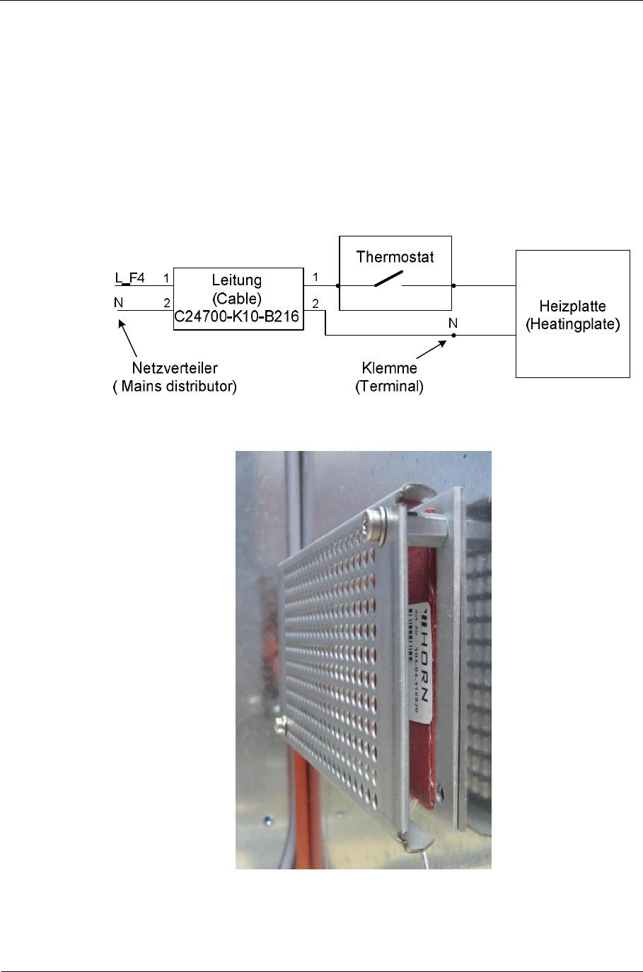
Sitraffic sX
Service manual controller technology 129
Components
Siemens AG V1.0 A001a / 2014-08-20
2.30. Cabinet heater
The cabinet heater is a panel heater, it is to be mounted at the bottom
right on the side wall in the main chassis. The thermostat sits at the left on
the rear wall on the bottom left top-hat rail. The thermostat should be set
to approximately +5°C
The heater set for this is as follows:
Heater set 230 V 40W /C10 L24730-E810-A31
Fig. 71: Activation of heater set
Fig. 72: View of cabinet heater
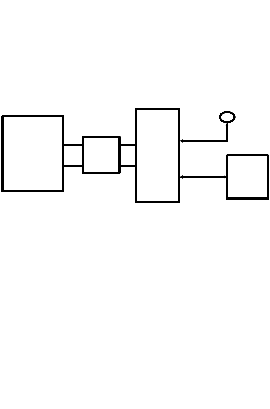
Sitraffic sX
Service manual controller technology 130
Components
Siemens AG V1.0 A001a / 2014-08-20
2.31. Control center activation
2.31.1. UMTS Router
For installation of the Canto P function in the sX there is the following
functional unit.
C10 Modem UMTS Set L24730-E813-A15.
UMTS
Router
(Max.
200mA)
CBU
X4
Antenne/
antenna
Ethernet
LAN-Kabel/
LAN-cable
CTB_X4.a16
(+24V_MOD_OUT)
CTB_X4.b15
( GND)
CTB
Leitung/ cable
C24700-K10-B77
11
2 2
Fig. 73: Activation of UMTS Router
The router is to be attached to the CTB: +24V_MOD_OUT. The current
consumption is 200mA max. That router could be connected to the UPS
module (USC).
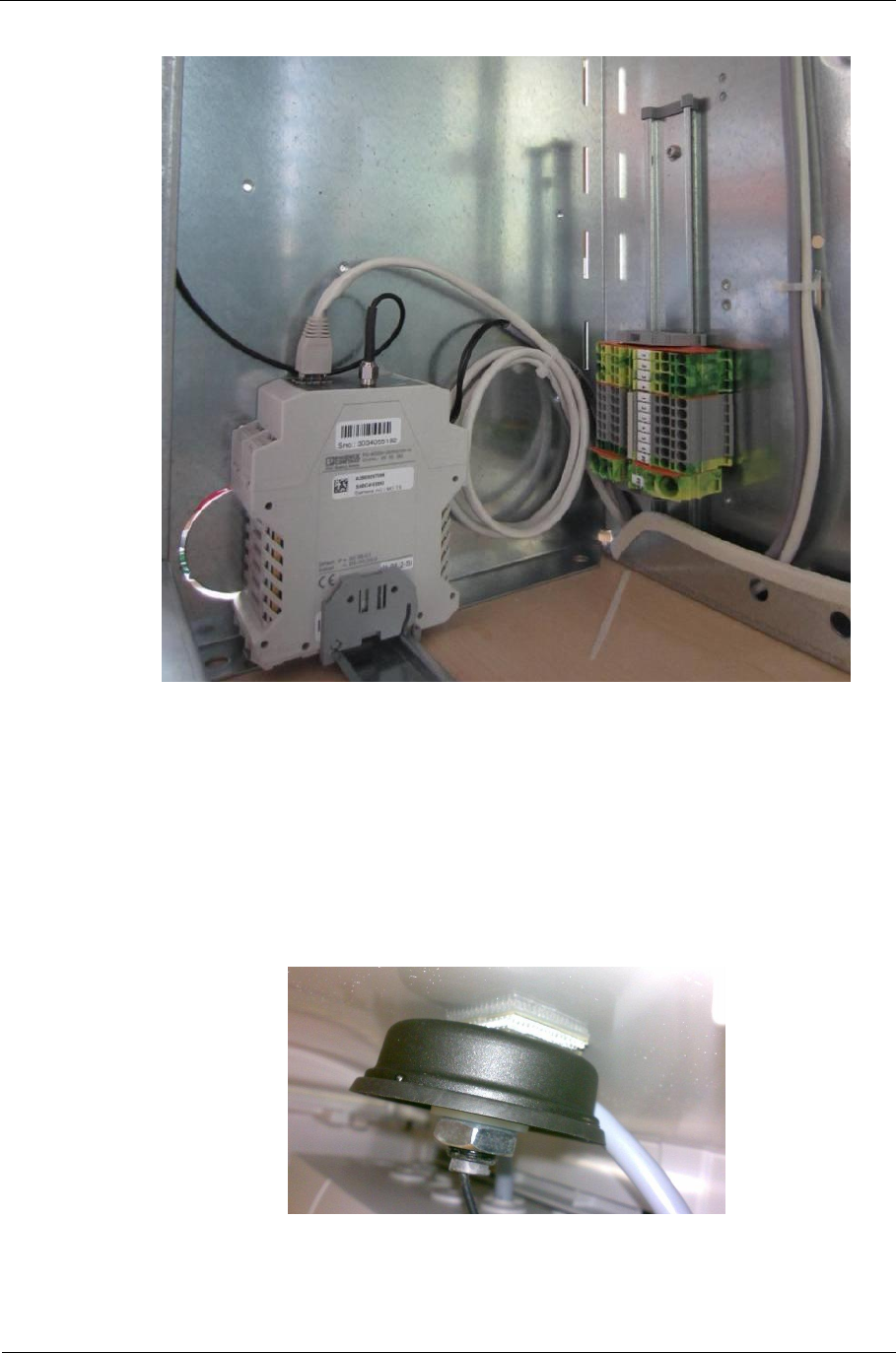
Sitraffic sX
Service manual controller technology 131
Components
Siemens AG V1.0 A001a / 2014-08-20
Fig. 74: UMTS router installation
Mounting of antenna:
The antenna is to be affixed to the roof with double-sided adhesive tape.
Here, take care to position the Velcro tape parallel to the longitudinal axis
of the roof curvature of the NKT cabinet. The thickness of the Velcro tape
thereby ensures the necessary adhesion of the entire surface.
Fig. 75: Mounting UMTS antenna
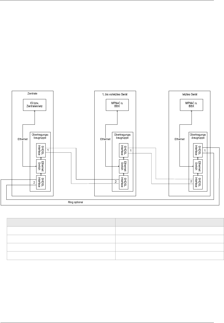
Sitraffic sX
Service manual controller technology 132
Components
Siemens AG V1.0 A001a / 2014-08-20
2.31.2. Canto P (DSL activation)
For Canto P with DSL, the modem with the name "Mini-Flex DSL Modem"
(item number A2B00095255) shall be used.
With a rising number of devices, the package delay increases. We therefore
presently only suggest up to 16 devices. Depending on the project,
however, larger loops can be tried out.
Moreover, using a loop (double spur line) the package delay can be cut in
half. For the arrangement of the loop, see Canto P description section 2.2.
German English
Zentrale Control center
1. bis vorletztes Gerät 1st to pre-last device
letztes Gerät Last device
Übertragungsbaugruppe Transmission module
Fig. 76: Canto P modem configuration
For installation in the sX, there is the following functional unit.
C10 modem Canto P set L24730-E813-A33.
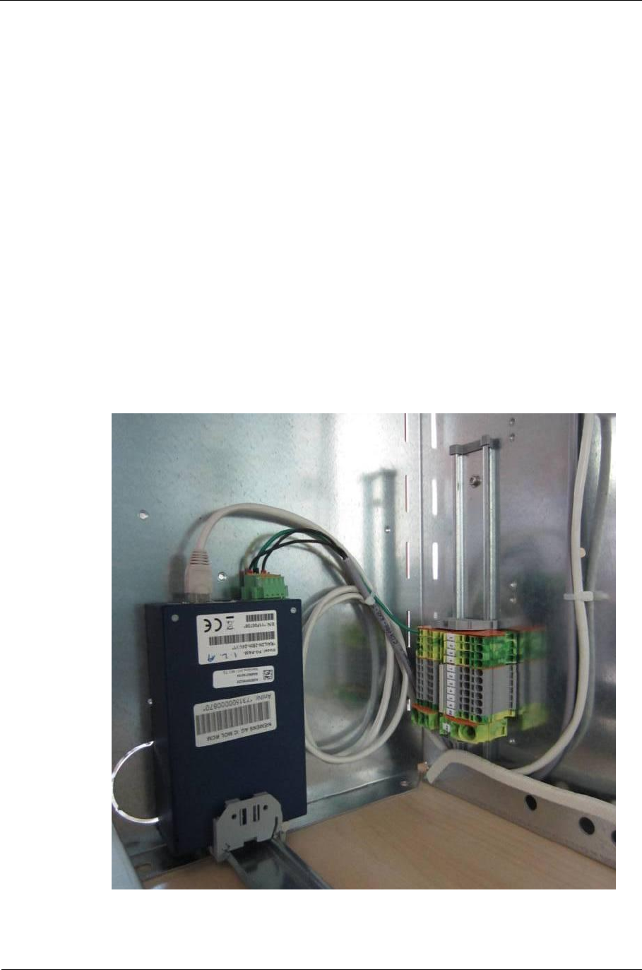
Sitraffic sX
Service manual controller technology 133
Components
Siemens AG V1.0 A001a / 2014-08-20
The necessary mounting parts are present in the set. The modem shall be
mounted on the left top-hat rail. Overvoltage protection is included in the
modem. For this reason, the PE wire absolutely must be connected. The PE
terminal is directly next to the modem.
After that, the Ethernet interface designated ETH1 shall be connected with
the Control Center-Ethernet interface of the CBU module using a crossover
patch cable (A2B00089079). (Connector CBU_X4).
Line 1 shall be connected with the ground cable leading to the field device.
Line 2 shall be connected with the ground cable leading to the control
center.
The maximum cable length between 2 modems is 6.3 km for 0.8mm wires
and 4.9 km for 0.6mm wires.
The modem is to be connected to the CTB: +24V_MOD_OUT. The current
consumption is 200mA max. That modem could be connected to the UPS
module (USC).
Fig. 77: Installation of Mini-Flex modem
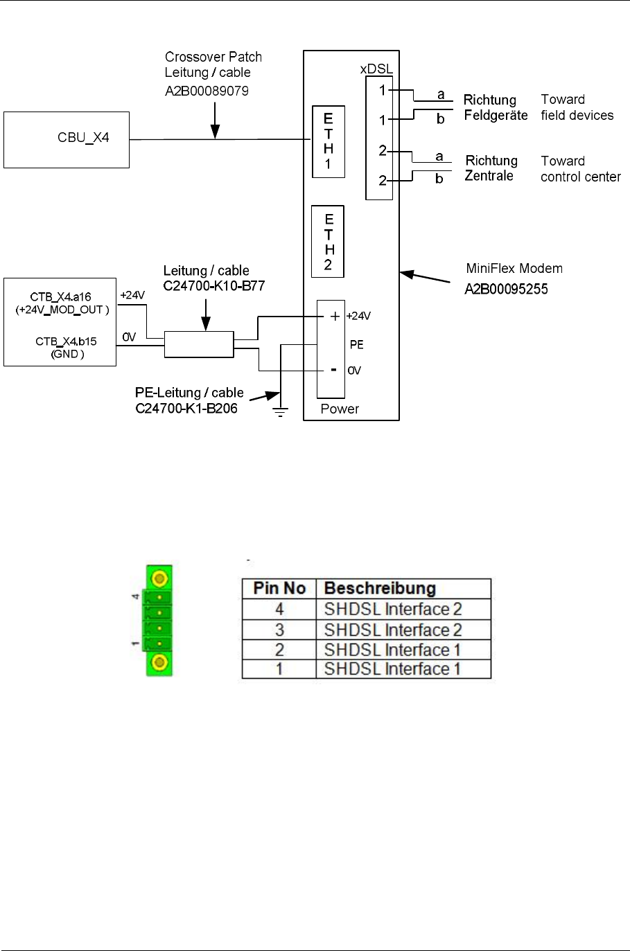
Sitraffic sX
Service manual controller technology 134
Components
Siemens AG V1.0 A001a / 2014-08-20
Fig. 78: Mini Flex connection in the device
SHDSL plug specifications
Description
Fig. 79: SHDL pinout for Mini Flex modem
Pinout for power supply
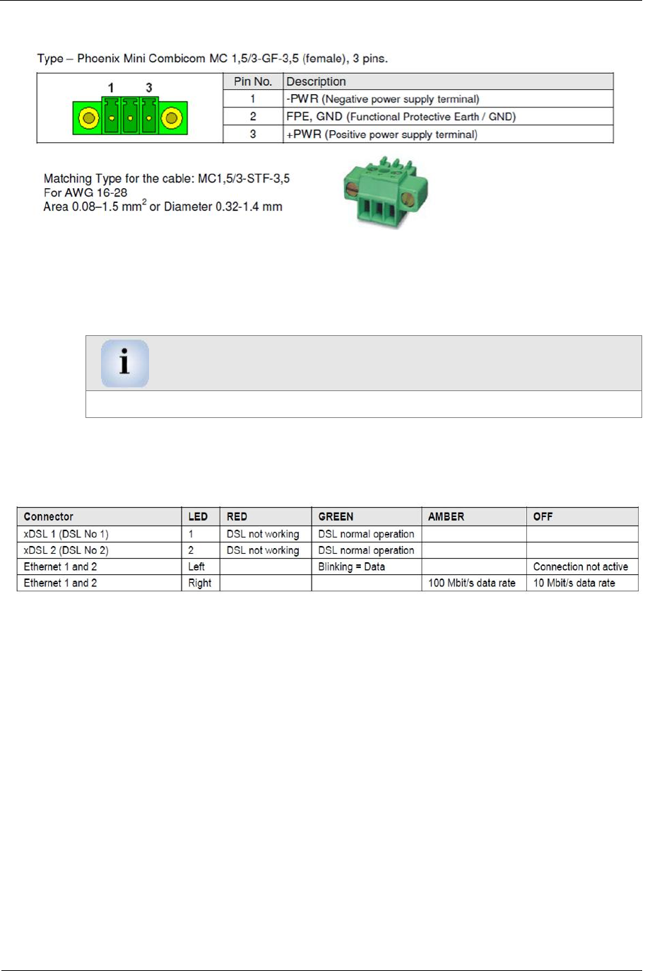
Sitraffic sX
Service manual controller technology 135
Components
Siemens AG V1.0 A001a / 2014-08-20
Fig. 80: Pinout for power supply of Mini Flex modem
Warning
For overvoltage protection, the PE absolutely must be connected.
Fig. 81: Meaning of the LEDs with the Mini Flex modem
Sitraffic sX
Service manual controller technology 136
Components
Siemens AG V1.0 A001a / 2014-08-20
2.32. UPS (USC is optional)
In order to be able to maintain operation of the OMC control module and
of a control center modem/router for several minutes in case of a power
failure, the sX controller can be equipped with a UPS of the type USC
(S24734-A633-A1). The USC makes it possible, if necessary, to transmit a
power failure message to the control center and properly shut down the
operating system. The USC is to be installed on the left side beside the CTB.
X4
Row/
Contact c b a
12 -- -- PF_USC_L
13 +5V_USC_IN +5V_USC_IN USC_OFF_L
14 GND GND +24V_USC_OUT
Tab. 68: Terminals of the CTB connection to the USC
Signal Signal direction
with reference
to CBU
Meaning
+24V_USC_OUT Output Charging current for the battery of
the USC
PF_USC_L Input Warning signal indicates that the
USC has taken over as the power
supply.
USC_OFF_L Output With this signal the USC can be
switched off if the operating system
has been shut down.
GND -- 0V
+5V_USC_IN Input Power supply for OMC and control
center modem CMA, if available.
Tab. 69: Meaning of the signals for the connection of a USC.
Independent of the terminals for connecting the CBU the USC has a +24V
output for the connection of CBU-external modems.
The required material is as follows:
■USC assembly set/C10 L24730-E810-A110
■USC complete L24730-E810-A100
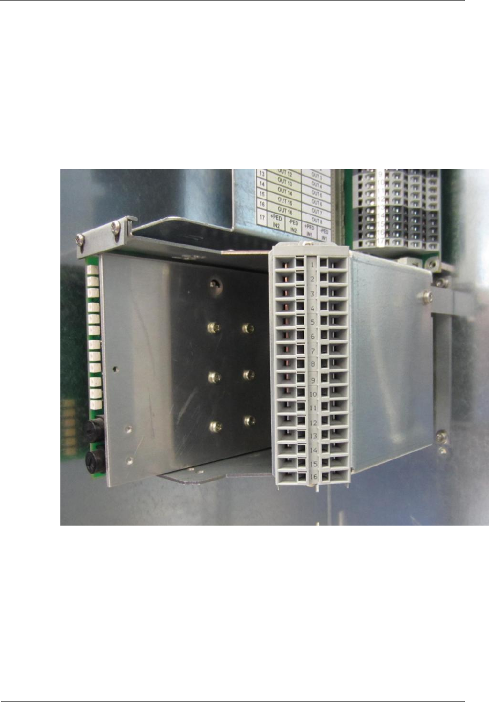
Sitraffic sX
Service manual controller technology 137
Components
Siemens AG V1.0 A001a / 2014-08-20
2.33. Special adapter CUA
With this adapter up to 2 system-external Europe cards can be installed.
The special adapter CUA is the size of a CLB cage and can be installed on
any CLB location. Furthermore, the CUA contains an FKA adapter for the
conversion of wrap technology to flat-belt technology as well as 16
connection terminals. The part number is:
C10 universal adapter CUA L24730-E815-A1
Fig. 82: Figure of CUA e.g. with 1x BFU module

Sitraffic sX
Service manual controller technology 138
Diagnostics
Siemens AG V1.0 A001a / 2014-08-20
3. Diagnostics
Further fault diagnostics are possible with the following tools:
■With the WEB GUI with the notebook contained in the controller
■With the supply and service tool SIEMENS Sitraffic core.
■With devices with control center via the control center.

Sitraffic sX
Service manual controller technology 139
Technical data
Siemens AG V1.0 A001a / 2014-08-20
4. Technical data
4.1. Standards
Requirement Standard
Requirement for traffic systems DIN EN 50556
With the classes required for Germany from
table 11 of the DIN VDE V 0832-110
Requirements for software traffic systems DIN EN 0832-500
Functional security Developed according to EN 61508 SIL3
Guidelines for light signal systems RiLSA
Controllers for traffic signal systems
Functional safety DIN EN 12675
Electromagnetic compatibility (EMC) DIN EN 50293
Safety of persons (EMF) DIN EN 62479
Safety, low-voltage directive DIN EN 60950-1:
Safety of transformers, power supply
units DIN EN 61558-1:
Environmental tests VDE 0832-100 1)
Climatic test in accordance with the classes:
AB3 (= + 60°C
AE4 (= - 40°C
AK2 (humid warmth 40°C/93% r.h
2x (12+12h)
Vibration test 2)
(according to EN60068-2-64 test Fh in
accordance with class AM2
Rohs Directive 2002/95/EC
The battery directive BattG Directive 2006/66/EC
REACH EU Regulation 1907/2006
EP standard EP standard no.1
Tab. 70: Standards
1) The listed values are better than required in VDE 0832-100
2) The listed values are better than required in DIN EN60068-2-64.

Sitraffic sX
Service manual controller technology 140
Technical data
Siemens AG V1.0 A001a / 2014-08-20
4.2. Characteristics of hardware and general
Installation in old cabinets Apart from the O cabinet, the sX-H can only be
installed in the N cabinet.
Other cabinets are not possible.
230 V -20 %, +15 %
Mains power connection:
Also covers 240 V , -24 %,
+10 %
Phase-to-zero mains connection Standard mains connection
Other fuses are needed for phase-to-phase mains
connections.
Mains connection components:
Fault current-actuated circuit-
breaker
device 300mA
Controller On/Off and Emergency OFF
Controller fuse 25 A fuse in the power supply company’s
compartment
Maintenance socket and fuse 10A
and 30 mA fault-current circuit
breaker
Standard German type
Fuse for controller Power distributor: 16 A, type C
2x fuse 4 AT
sX-Hx power distributor2: 4 AT
Fuse for LED power supply Power distributor: 16 A, type B
- on the CPDH 6.3A per LED switch (LSHS)
- 1 A per color output of the LSHS
Basic surge protection Simple surge protection on the
mains supply line as standard.
Increased surge protection possible optionally.
Fuse for traffic signs and other
devices operated with mains voltage. 1*4safety fuses for the power distributor
(for higher loads you will need to retrofit a fuse in
the power supply company’s compartment
).
Local mains connection peculiarities The preferred size 2O/2N cabinet provides the
familiar installation space.
Internal power supply:

Sitraffic sX
Service manual controller technology 141
Technical data
Siemens AG V1.0 A001a / 2014-08-20
24 V DC/ 2 A Sufficient to power
all system modules in the preferred configuration.
An additional
power supply will be needed for pedestrian
acknowledgment lamps.
2*13 V AC APU transformer for the LSHS supply voltage
LED voltage 230 V AC
Power supply voltages 230 V Yes
(Ph or Ph-to-Ph)
LED switch technology:
Electronic load switches Only electronic LED switches are used
230 V LED switches in the device An LED switch module (LSHS) covers
24 load switches, divided into 8 signal groups
(2x red current monitors, yellow + green,
unmonitored red is also accessible for signal
group 1-4. (=> 4 * 8 = 32 +4 = 36 outputs)
Maximum load per LSHS load switch: 72W.
Maximum load per red1 and red2 output 36 W
Total current monitoring/ available
available
analog inputs
LED types:
230 V LED (5-18W) The LED signal head type must have been
technically released for
operation on the sX-H controller.
Number of signal groups:
Total Max. 64
Number of LED switches maximum 8, maximum 4 per cabinet
Total load for device At 230 V: 2760 W (12 A)
Power rating of LSHS module: Maximum 920 W (4 A)
Vibrating signals for the visually
impaired for 230 V Normal output
Limit values for red monitoring 5W

Sitraffic sX
Service manual controller technology 142
Technical data
Siemens AG V1.0 A001a / 2014-08-20
Minimum load per monitored
output: 5W
Signal types: Three possible connections for each output.
Monitoring can be deactivated by software.
3-aspect:
Combined signals (tactile +
pedestrian) Tactile and acoustic signal heads via CIAC module
or via LSHS outputs
color-dependent minimum times
Other: 230 V types (threshold relay)
Crossing signal for the visually
impaired/
Special signals 40V types direct via LSHS
Pedestrian acknowledgment 230 V Via unused outputs from LSHS or via
I/O module CIAB/CIAC
Pedestrian acknowledgment 24 V DC Via additional IO module CIE/CIO
Tactile signals for the visually
impaired. Normal 230 V LSHS output
Inputs/Outputs :
Maximum number of outputs that
can be handled by the basic
software: up to 250 8 high-side outputs 24 V/150 mA
contained in the basic configuration
Maximum number of inputs that can
be handled by the basic software: up
to 250
8 inputs included in the basic configuration
Detection In the 10ms grid
Not electrically isolated, 24 V DC,
overvoltage protection present
Loop detectors of type SLD4 that can
be plugged into 2 SLD4 module in the basic configuration;
the occupancy and fault outputs for each loop are
recorded
in series.
For every 4 loops
Expansions for inputs / outputs up to 17 CLB modules can be installed
8 loops possible for each CLB

Sitraffic sX
Service manual controller technology 143
Technical data
Siemens AG V1.0 A001a / 2014-08-20
IO expansion 16 inputs/16 outputs 24 VDC possible for every
CLB
12 inputs/12 outputs 230 VAC possible for every
CIAB
Video DIB-E can be plugged into CLB/CBU
Wrap/ soldering installation part CUA adapter
Serial interfaces: Included on the basic module
Connection to GPS for GPS receiver
Control center connection Canto P DSL modem
UMTS router
Control center connection OCIT, CANTO
Connection to PC For Sitraffic Core programs
Connection to display For command unit BAZ with display 4x20
characters
Time generation:
Real-time clock (battery buffered) Time source for startup and after power
interruption
GPS Time synchronization with GPS receiver
Time server Time alignment via synchronization
with a time server (ntp)
Operation:
Display and control panel BAZ Functionality as per EN 50556
Control panel with display (BAZ)
Full diagnostics facilities via an
external PC PC tool Sitraffic Service with
extended function range
Diagnostics:
LED displays for the principal
functions See description of modules
Built-in test functions Memory test and consistency check of the supply
data
in main memory on booting and while
in operation.
Extended diagnostics via switchable
operator panels displays Display of:
Operating log/ SiMo log messages
Device status, defective red lamps and detectors
Other special displays (e.g TA, PT, etc.)
Full diagnostics facilities via an PC tool Sitraffic Service with

Sitraffic sX
Service manual controller technology 144
Technical data
Siemens AG V1.0 A001a / 2014-08-20
external PC extended function range
Features of the signal monitor
Interfacing to outdoor
installations:
Ground cable goes to LED switch via
isolating terminals, maximum wire
diameter 2.5 mm2
Terminals on the LED switch backplane (CDBH)
3 terminals per output
up to 250m
Standard line length
Voltage monitoring: Factory setting is -20 % to +15 % of the rated
voltage
Undervoltage and overvoltage
Signal groups: Maximum number is 64
Switch-off time in the event of
a fault: <300 ms
Off-signaling:The signal group status for each Off signaling can
be supplied for each signal group.
Off-flashing pattern (secondary
direction) This can be selected by all operators (PC,
command unit, control center)
All off This can be selected by all operators except the
control center.
All-yellow flashing Can be selected from PC and command unit
Fault flashing User-definable, e.g. fault flashing via
"All yellow" after SiMo fault (fault occurrence)
Maintenance and diagnostics:
Low-maintenance design, self-test of
the principal functions
Internal archive, information
interface to controller
Fast test of the configuration SiMo test of the controller with the PC
Operating status displays LEDs on modules, optional LCD on BAZ, PC

Sitraffic sX
Service manual controller technology 145
Part numbers, modules
Siemens AG V1.0 A001a / 2014-08-20
5. Part numbers, modules
Modules in alphabetical order
Name Part number Description
BAZ2 L24734-F655-A5 BAZ 2 Module Cxx0/C10
CBU S24734-A870-A10 CBU compl HW with initial program loader /C10
CCU V24734-Z894-A1 CCU set C10 GPS internal /C10
CCUE V24734-Z895-A1 CCUE set C10 GPS external /C10
CDBH S24734-A872-A1 CDBH C10 Power Distrib. Backp. 230 V /C10
CEB S24734-A875-A1 CEB C10 Extension Board /C10
CEW S24734-A898-A1 CEW C10 Electronic load LSHS /C10
CIAB S24734-A897-A1 CIAB C10 CIAC Backplane /C10
CIAC S24734-A896-A1 CIAC C10 I/O AC 24V/230 V /C10
CIE S24734-A877-A1 CIE C10 IO Board-+Ethernet /C10
CIO S24734-A890-A1 CIO C10 IO Board /C10
CLA S24734-A878-A1 CLA C10 Loop Adapter /C10
CLB S24734-A879-A1 CLB C10 Loop Detector Backplane /C10
CLBT S24734-A891-A1 CLBT C10 CLB Termination /C10
CMD S24734-A899-A1 CMD C10 Mode and Display /C10
CPA S24734-A883-A1 CPA C10 Power Distribution Adapter /C10
CPDH S24734-A884-A1 CPDH C10 Power Distrib. Unit 230 V /C10
CTB S24734-A871-A1 CTB C10 Terminal Board /C10
DIB-E ZNX:DET-089-000151 Video detector interface for Sivicam (Flir co.)
Dongle Can only be ordered via function generator
LSHS S24734-A887-A1 LSHS Lamp Switch 230 V Serial /C10
OMC-U S24777-A3534-A20 Outstation Main Controller U-Version
SIVICAM I-2 ZNX:DET-089-000245 Integrated video detector with 3 mm lens
SIVICAM I-2 ZNX:DET-089-000246 Integrated video detector with 8 mm lens
SLD4 S24763-A82-A6 Serial Loop Detector
UMTS Router A2B00097096 UMTS Router C9x0 /CANTO
USC S24734-A633-A1 USC module
DSL Modem A2B00095255 Mini Flex SHDSL Modem /CANTO
24V DC PS V24069-Z8043-A1 24 V DC power supply
48V DC PS V24069-Z8045-A1 48V DC power supply
Tab. 71: Module part numbers

Sitraffic sX
Service manual controller technology 146
Part numbers for installation sets
Siemens AG V1.0 A001a / 2014-08-20
6. Part numbers for installation sets
Part number Description
L24730-E800-A3 Expansion unit or door /C10
C24734-A16-B233 Front door, large /C10
L24730-E810-A100 USC complete /C10
L24730-E810-A110 USC assembly set /C10
C24700-K10-B180 CBU-BAZ /C10 cable
C24734-A16-B999 Accessory kit for BAZ 2 module /CXX
L24730-E810-A31 Heater set 230 V 40W /C10
L24730-E810-A35 BAZ prepared externally /C10
L24730-E810-A41 Transformer set 25VA /C10
L24730-E810-A45 Transformer Set 50VA /C10
L24730-E810-A60 CCUE-Set GPS external complete /C10
L24730-E810-A61 CCUE prepared /C10
L24730-E810-A70 CCU GPS internal complete /C10
L24730-E811-A40 CIAB bracket set /C10
L24730-E811-A100 CLB angle set /C10
L24730-E811-A200 CIAB Backplane /C10
C24700-K10-B215 Line 700mm (2x1) /C10
L24730-E811-A4 CIAB terminal set /C10
L24730-E811-A21 CIAC assembly set 117/230 V /C10
L24730-E812-A3 C10 CLA1 set
L24730-E812-A4 C10 CLA2-HX set
L24730-E812-A12 C10 DIB-E-Set
L24730-E813-A15 Modem Set UMTS /C10
L24730-E813-A33 Modem Set Canto-P MiniFlex /C10
L24730-E814-A1 PS SET 24V AC 60VA /C10
L24730-E814-A2 PS SET 24V DC 48W /C10
L24730-E814-A3 PS SET 48V DC 48W /C10
L24730-E814-A14 Mounting bracket for power supply set /C10
L24730-E815-A1 Universal adapter CUA /C10
L24734-A872-A10 CDBH Set /C10
L24734-A887-A10 LSHS Set /C10
L24730-E821-A2 CEW 230 V set /C10

Sitraffic sX
Service manual controller technology 147
Part numbers for installation sets
Siemens AG V1.0 A001a / 2014-08-20
Part number Description
L24730-E821-A100 CPDH accessories /C10
L24730-E821-A210 CPA Power Distribution Adapter high/C10
S24734-B825-A1 Power supply company unit C10-H 230 V/25A
/C10
S24734-B825-A2 Power supply company unit C10-H Ph-to-Ph
230 V/25A /C10
L24764-Z2000-A112 Wimag Basis Set /C10
L24730-A899-A1 Set 20 x micro fuse 6.3A CPDH /C10
L24730-A899-A2 Set 20 x SMD fuse 1A LSHS/C10
L24730-A899-A3 Set 20x fuse 1AT CIAC /C10
L24730-A899-A4 Set 20x fuse 4AT power distributor C10
C24700-K10-B97 PDU/ CPDH charging cable 6pin 2m /Cx40ES/C10
C24407-Z7-C1 Modules for removal tool
Panasonic BR2032 Replacement battery OMC
Wago: 2009-309 Wago Top Jop tool
(for the terminal blocks)
Tab. 72: Set part numbers

Sitraffic sX
Service manual controller technology 148
Abbreviations
Siemens AG V1.0 A001a / 2014-08-20
7. Abbreviations
AFD General radio demodulator for PT
APU Auxiliary Power Unit
BAZ2 Display and command unit
BFD Bus interface for detectors Cxx0x
BFU Pedestrian module Cxx0x
CBU CBU compl HW with initial program loader /C10
CCUE Set CCUE set C10 GPS external /C10
CCU Set CCU set C10 GPS internal /C10
CDBH CDBH C10 Power Distrib. Backp. 230 V /C10
CEB CEB C10 Extension Board /C10
CEW CEW C10 Electronic load LSHS /C10
CIAB CIAB C10 CIAC Backplane /C10
CIAC CIAC C10 I/O AC 24V/230 V /C10
CIE CIE C10 IO Board-+Ethernet /C10
CIO CIO C10 IO Board /C10
CLA CLA C10 Loop Adapter /C10
CLB CLB C10 Loop Detector Backplane /C10
CLBT CLBT C10 CLB Termination /C10
CMD CMD C10 Mode and Display /C10
CPA CPA C10 Power Distribution Adapter /C10
CPDH CPDH C10 Power Distrib. Unit 230 V /C10
CTB CTB C10 Terminal Board /C10
DIB-E Video detector interface for Sivicam (Flir co.) Cxx0V /C10
Dongle Dongle
DPSK Modulation mode (differential frequency shift keying)
EMC Electromagnetic compatibility
ESB Switch-on current limiter
EVU Power supply
FEE Radio receiver
FEU Frequency changeover module (for AFD)
FFSK Modulation mode (fast frequency shift keying)
FI Fault current circuit-breaker
FKA Ribbon adapter for connecting ribbon cable
GPS Global Positioning System

Sitraffic sX
Service manual controller technology 149
Abbreviations
Siemens AG V1.0 A001a / 2014-08-20
HW Hardware
IFB Display and command unit interfaces
IO Input/Output
KLZ Terminal board control center
LED Light emitting diode
TSS Traffic signal system
LSHS LSHS Lamp Switch High voltage (230 V) Serial /C10
OMC-U Outstation Main Controller U-Version
PT Public Transport
PSU Power Supply Module
RILSA Guidelines for light signal systems
SIMO Signal monitoring
SLD4 Serial Loop Detector
SRAM Static random access memory (not cyclically updated)
PS Power supply
TEB Drivers for an external display and command unit
PI Partial intersection
UPS Uninterruptible power supply
TA Traffic-actuation logic
VDE VDE standards/regulations
TCC Traffic control computer

Sitraffic sX
Service manual controller technology 150
Index
Siemens AG V1.0 A001a / 2014-08-20
8. Index
A
Add-on chassis 23
B
Battery replacement 55
BAZ
display 119
external 120
installation 120
C
Cabinet
frames 14
heater 129
Canto P 132
CBC 34
display 46
operating states 46
CBU 31
control elements 40
interfaces 38
reset 45
setting the operating mode 45
CCU
internal 122
CCUE
external 123
CDBH 69
CEB 51
CEW 68
CHX 35
CIAB 108
internal activation 230V 115
setting address 110
structure 110
terminal assignment 111
CIAC 108
breakdown 111
head connector 113
LEDs 112
CIE/CIO
base connector 94
function 92
head connector 93
CLA 85
CLB
installation location 78
installation locations 78
CLBT 84
CMD 44
CMU 36
Control unit 34
CPA 72
CPDH 59
CUA 137
D
DIB-E
activation at the CBU 107
front 99
interface 98
F
Fault diagnostics 138
Frame construction 11
H
Hardware concept sX 10
L
LSHS 64
M
Main chassis 22
N
Network topologies 103
O
OMC 34
OMC-U 52

Sitraffic sX
Service manual controller technology 151
Index
Siemens AG V1.0 A001a / 2014-08-20
P
Power connection 30
Power distributor 27
Power supplies 30
S
Safety notes 9
SLD4 86
uplink/downlink 88
Supplementary power supply
24V AC 127
24V DC 124
Switch-off routes 23
sXHardware concept 10
Technical concept 10
sX-H
basic version 20
components 12
power supply 17
structure 18
sX-Hx 75
U
UMTS router 130
UPS 136
Utility compartment 25
V
video detectors 98
W
Wimag activation 97

Title Text
Document Specification 152
Index
Siemens AG V1.0 A001a / 2014-08-20
More information
is available from:
Siemens AG
Infrastructure and Cities Sector
Mobility and Logistics Division
Road and City Mobility
Otto-Hahn-Ring 6
81739 Munich, Germany
The information in this guide contains
performance attributes that can
change with further development of
the products. The requested features
are only binding if they are expressly
agreed upon in a contract of sale.
Order no. A24730-A890-A008
Siemens Aktiengesellschaft
© Siemens AG 2014
All rights reserved
Sitraffic® is a registered trademark of Siemens AG.
www.siemens.de/traffic
