Bamocar NDrive Manual
User Manual:
Open the PDF directly: View PDF ![]() .
.
Page Count: 117 [warning: Documents this large are best viewed by clicking the View PDF Link!]
- 1.1
- 2 Basic information
- 3 Start screen
- 4 Help
- 5 Storage
- 6 Selection of the communication interface
- 7 Measured values
- 8 Conversion
- 9 Errors
- 10 Enable
- 10.1 Hardware - Enable FRG/RUN
- 10.2 Safety
- 10.3 Settings
- 10.4 Motor setting
- 10.5 Setting window for the feedback encoder
- 10.6 Setting window for the feedback encoder
- 10.7 Setting X8 as second counter input
- 10.8 Brake setting
- 10.9 Ballast circuit setting
- 10.10 Motor temperature setting
- 10.11 Setting of the power connection/bus circuit
- 10.12 Output stage temperature
- 10.13 Setting field for rated servo data
- 10.14 Setting field for rated servo data
- 10.15 Command value setting
- 10.16 BTB / RDY setting
- 11 CAN-BUS settings
- 12 Parameter
- 13 Field weakening at synchronous motors
- 14 Torque control
- 15 Position controller parameters
- 16 Frequency converter parameters
- 17 Logic
- 18 Diagnosis
- 19 Monitor
- 20 Options
- 21 Automatic setting functions
- 21.1 Setting window Auto
- 21.2 Tuning still (0x85-1)
- 21.3 Tuning rotating (0x85-2)
- 21.4 Phasing still (0x85-3)
- 21.5 Measuring the encoder offset (phase angle)
- 21.6 Preset current feed angle (0x85 – 5)/fixed motor position (0x85-5)
- 21.7 Analog offset (0x85 -6)
- 21.8 Tacho offset (0x85 -7)
- 21.9 Calc from Motorplate (0x85-8)
- 21.10 VdcBus Adjustment
- 22 Oscilloscope
- 23 Parameters
M A N U A L
PC Software Manual
for the Servo Amplifier DS, DPC
and the Battery Drives
BAMO-D, BAMOBIL-D, BAMOCAR-D
Industrie Elektronik
G m b H
Hans-Paul-Kaysser-Straße 1
71397 Leutenbach – Nellmersbach
Edition /
Version
Tel.: 07195 / 92 83 – 0
Fax: 07195 / 92 83 – 129
contact@unitek.eu
www.unitek.eu
2017 V 1
NDrive.3

Basic information
1
Version 2017 / V1
Software – Manual N-Drive 3xx
1 Contents
2 Basic information ............................................................................................................. 4
2.1 History ................................................................................................................................ 4
2.2 Further manuals for digital UniTek units: .......................................................................... 4
2.3 General ............................................................................................................................... 5
2.4 Safety advice: ..................................................................................................................... 5
2.5 Operating system ............................................................................................................... 5
2.6 Software installation .......................................................................................................... 6
2.7 Communication RS232 (COMx) .......................................................................................... 6
3 Start screen ...................................................................................................................... 7
3.1 Description ......................................................................................................................... 7
3.2 Operation ........................................................................................................................... 9
3.3 Entry and selection ........................................................................................................... 10
4 Help ............................................................................................................................... 11
4.1 Direct help ........................................................................................................................ 11
5 Storage .......................................................................................................................... 12
5.1 Storage in the controller .................................................................................................. 12
5.2 Storage to the pc .............................................................................................................. 12
6 Selection of the communication interface ....................................................................... 13
6.1 Display of a saved file (*.urf) in the NDrive ..................................................................... 13
6.2 Firmware update .............................................................................................................. 14
7 Measured values ............................................................................................................ 15
7.1 Table of measured values ................................................................................................ 15
7.2 Table / measured value .................................................................................................... 16
8 Conversion ..................................................................................................................... 17
8.1 Conversion of the measurement units ............................................................................. 17
9 Errors ............................................................................................................................. 18
9.1 Error list ............................................................................................................................ 18
9.2 Warnings .......................................................................................................................... 19
9.3 States ................................................................................................................................ 21
9.4 Display of inputs and outputs .......................................................................................... 22
10 Enable ........................................................................................................................ 23
10.1 Hardware - Enable FRG/RUN............................................................................................ 23
10.2 Safety ................................................................................................................................ 25
10.3 Settings ............................................................................................................................. 27
10.4 Motor setting ................................................................................................................... 28
10.5 Setting window for the feedback encoder ....................................................................... 30
10.6 Setting window for the feedback encoder ....................................................................... 31

Basic information
Software – Manual N-Drive 3xx
Version 2017 / V1
2
10.7 Setting X8 as second counter input .................................................................................. 32
10.8 Brake setting ..................................................................................................................... 33
10.9 Ballast circuit setting ........................................................................................................ 35
10.10 Motor temperature setting .......................................................................................... 36
10.11 Setting of the power connection/bus circuit ............................................................... 39
10.12 Output stage temperature ........................................................................................... 40
10.13 Setting field for rated servo data ................................................................................. 41
10.14 Setting field for rated servo data ................................................................................. 42
10.15 Command value setting ................................................................................................ 43
10.16 BTB / RDY setting .......................................................................................................... 47
11 CAN-BUS settings ........................................................................................................ 48
11.1 Settings CAN-BUS ............................................................................................................. 48
11.2 Aufbau serielles Protokoll ................................................................................................ 49
11.3 Interface RS232 ................................................................................................................ 50
12 Parameter ................................................................................................................... 51
12.1 Current controller parameters ......................................................................................... 51
12.2 Current reduction parameters ......................................................................................... 54
12.3 Current reduction functions ............................................................................................. 55
12.4 Current controller parameters ......................................................................................... 56
12.5 Speed controller parameters ........................................................................................... 59
12.6 Speed controller parameters ........................................................................................... 62
12.7 Speed controller optimization .......................................................................................... 65
13 Field weakening at synchronous motors ...................................................................... 67
13.1 Field weakening mode ..................................................................................................... 67
14 Torque control ............................................................................................................ 69
14.1 Torque control .................................................................................................................. 69
15 Position controller parameters .................................................................................... 70
15.1 Setting of the position controller ..................................................................................... 70
15.2 Reference run ................................................................................................................... 74
15.3 Position controller optimization ....................................................................................... 76
15.4 Position scaling ................................................................................................................. 77
16 Frequency converter parameters ................................................................................. 78
16.1 Frequency converter parameters ..................................................................................... 79
17 Logic ........................................................................................................................... 80
17.1 Logic setting window ........................................................................................................ 80
17.2 Digital inputs ..................................................................................................................... 81
17.3 Digital outputs .................................................................................................................. 82
17.4 Logic links ......................................................................................................................... 84

Basic information
3
Version 2017 / V1
Software – Manual N-Drive 3xx
18 Diagnosis .................................................................................................................... 85
18.1 Diagnosis window ............................................................................................................. 85
18.2 Manual read/write ........................................................................................................... 86
18.3 Track display field ............................................................................................................. 86
18.4 Information ...................................................................................................................... 87
19 Monitor ...................................................................................................................... 88
19.1 Measured values .............................................................................................................. 88
20 Options ...................................................................................................................... 89
20.1 Recuperation for vehicles (Brake Car) .......................................................................... 89
21 Automatic setting functions ........................................................................................ 90
21.1 Setting window Auto ........................................................................................................ 90
21.2 Tuning still (0x85-1) .......................................................................................................... 92
21.3 Tuning rotating (0x85-2)................................................................................................... 92
21.4 Phasing still (0x85-3) ....................................................................................................... 92
21.5 Measuring the encoder offset (phase angle) .................................................................. 93
21.6 Preset current feed angle (0x85 – 5)/fixed motor position (0x85-5) ............................... 94
21.7 Analog offset (0x85 -6) ..................................................................................................... 95
21.8 Tacho offset (0x85 -7) ...................................................................................................... 95
21.9 Calc from Motorplate (0x85-8) ........................................................................................ 96
21.10 VdcBus Adjustment ..................................................................................................... 98
22 Oscilloscope ............................................................................................................... 99
22.1 Overview .......................................................................................................................... 99
22.2 Oscilloscope settings ...................................................................................................... 100
22.3 Arrow key for the channel selection .............................................................................. 101
22.4 Trigger settings ............................................................................................................... 102
22.5 Display of measured values ............................................................................................ 103
22.6 Parameters on the oscilloscope page ............................................................................ 104
22.7 Test operation ................................................................................................................ 104
23 Parameters ................................................................................................................ 105
23.1 Parameter tables ............................................................................................................ 105

Basic information
Software – Manual N-Drive 3xx
Version 2017 / V1
4
History
2 Basic information
2.1 History
Version
Modifications
Date
2016 / V1.1
Fax-Number / page 68 (lq – complete)
02.08.2016
2017 / V1
Error-List / Parameter
14.11.2017
Note :
Only use NDrive3xx for units from firmware FW-350 on (from serial no. 70000)
2.2 Further manuals for digital UniTek units:
1.
MANUAL
DPC 4xx-AC DSxx, BAMO-D3, BAMOBIL-Dx
Hardware description
2.
MANUAL
DSxx, BAMO-D3, BAMOBL-Dx
Commissioning
3.
MANUAL
CAN
BUS system
Use all manuals for the planning, the installation, and the commissioning!
Included as CD version in the equipment delivery (UNITEK-DOKU-SOFT).
Online: www.unitek.eu
MANUAL includes warning and safety notes, descriptions to standards and regulations ,
and mechanical and electrical installation notes.
The MANUAL must be available at any time for all persons dealing with the unit.
Short symbols/terms
Servo Digital UNITEK motor controller
Unit Digital UNITEK motor controller
PC Personal computer, notebook
Basic information
5
Version 2017 / V1
Software – Manual N-Drive 3xx
General
2.3 General
The software NDrive3 is used to set-up and optimize UNITEK digital servo amplifiers (DS, DPC) and
motor drives (BAMO-D, BAMOBIL-D, BAMOCAR-D).
Basic computer skills and fundamental knowledge of the Windows software are required.
The NDrive3 software and the respective manual are available on CD or via the internet.
2.4 Safety advice:
The parameters and settings of the controller (servo amplifier)
and the motor are preset with the software NDrive3.
Operating parameters can be preset and changed during
operation. The computer and the PC programs are not
malfunction-proof.
The user must ensure that in case of malfunctions neither
personnel nor machines are endangered and that the drive is
stopped.
Saved data can be changed by third parties. Any imported data record must be checked prior to
re-use.
Any adjustments or optimising work on the running drive must only be carried out by trained
competent personnel with knowledge of drive and control engineering and computer handling.
Further to this, the safety advice for the amplifier and the drive used must be observed.
Any operation not conform to the safety guidelines is not permissible.
2.5 Operating system
NDrive will operate with WINDOWS 2000 and WINDOWS NT4, WINDOWS XP, Windows Vista
Min. required PC equipment
Processor
80486 or superior
Graphics
WINDOWS compatible
Hard drive, available capacity
3MB
Floppy disc drive
3.5“
CD drive
CD ROM
RAM, min.
8MB
Interface
COM1 or COM2 (RS232, USB adapter)
WINDOWS is a registered trademark of Microsoft Corp.
Basic information
Software – Manual N-Drive 3xx
Version 2017 / V1
6
Software installation
2.6 Software installation
The user software NDrive3 can be copied.
An installation program is not required.
From a CD
(Compact Disc Unitek-Doku-Soft-Vx)
Copy the software file (NDrive-x digital Servo) from the CD to the hard drive (do not install).
Open the NDrive-x-Aktuell-Vxx,
start the software file NDrive-x-Vxx.exe with a double click.
Via the internet
Log into www.unitek.eu or www.unitek-online.de. Click software button.
Download and save the software (NDrive-x-Software.zip).
Decompress in the NDrive-x-software-Vxx and start the software file NDrive-Vxx.exe with a
double click.
NDrive ICON
Right click on the software file NDrive-Vxx.exe. Send to the desktop.
The icon is displayed on the desktop as shortcut to NDrive-Vxx.
Double click the desktop icon to start NDrive-Vxx
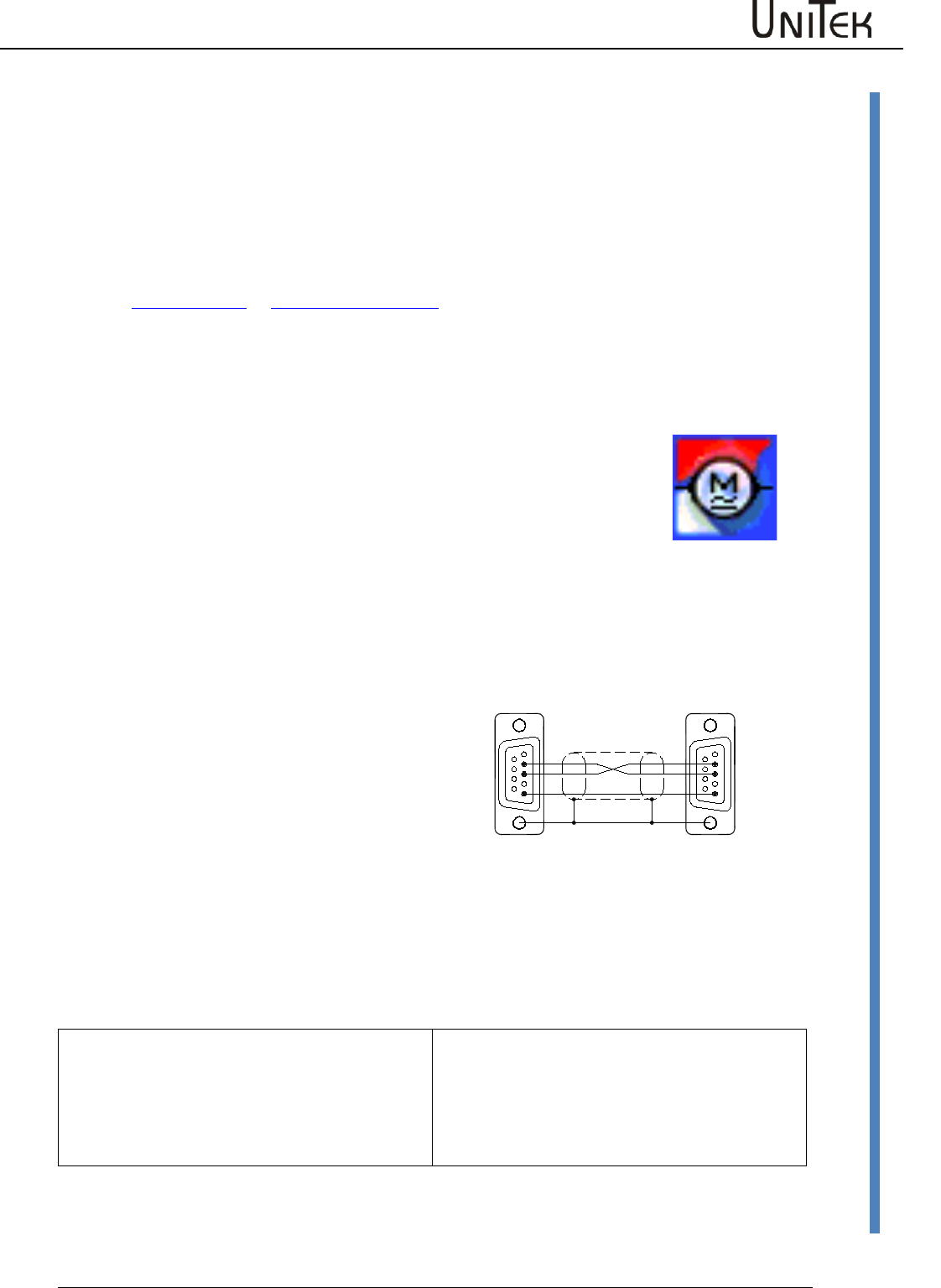
2.7 Communication RS232 (COMx)
Software communication between the PC and
the servo amplifier is effected via RS232.
115200 baud rate.
The connecting cable is a null modem type
cable.
Do not use a null modem link cable!
Use an USB-RS232 adapter with PCs with an
USB interface.
Use the USB adapter RS323 for PCs with an
USB interface.
Plug and unplug the connecting cable only
when the interface is disconnected.
The interface is galvanically connected to
device ground (AND).
Communication USB (COMx) (TMS-DEIF)
USB connecting cable with a xxxx connector on
the device side. Baud rate 115200.
Plug or unplug the connecting cable only if the
interface is isolated.
The interface is galvanically isolated from the
device zero (AND).
Icon_32x32
DS400-RS232-Verb.
Schirm am Steckergehäuse
62
5
FM
4
3
7
8
9
16
FM
7
8
9
2
5
4
3
1
RxD
TxD
GND GND
TxD
RxD
RS232 PC DSxx/BAxx
X10
Shield at connector housing
Start screen
7
Version 2017 / V1
Software – Manual N-Drive 3xx
Description
3 Start screen
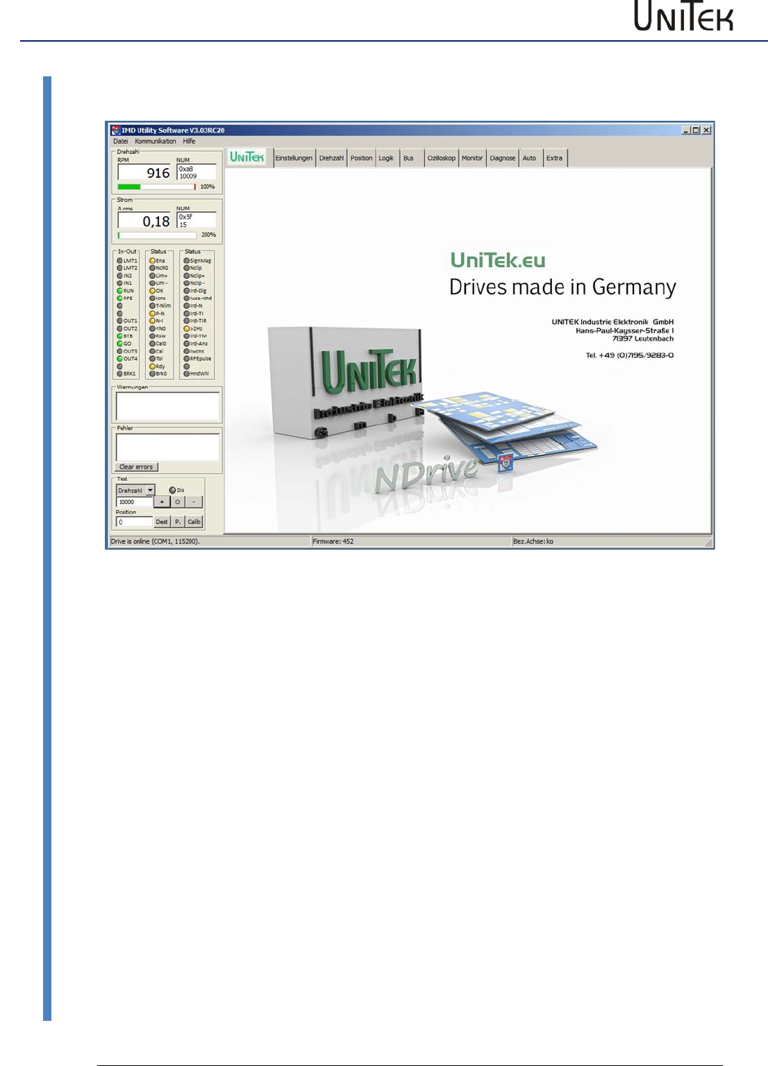
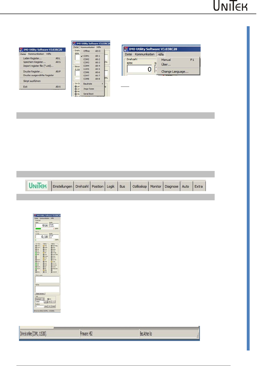
3.1 Description
The program presents a screen consisting of two elements. A constant outer frame (grey) and an
interleaved page area (blue). The pages are accessed by a horizontal tab bar running across the
top of the frame
Top
Title bar, menu bar, page tabs
Left
Display of speed, current, inputs and outputs, states, errors, and test
functions
Bottom
Setup states
UNITEK symbol
Link to the Unitek website
The screen surface switches between pages.
The tab structure allows for easy access of relevant data and fast switching between the pages.
The grey frame surface is constantly displayed.
The selected pages are opened across the complete blue area.
It is always possible to switch between the pages without a time delay.
Multi-page parameters are automatically transferred. Settings referring to only one page remain
unaffected.
Start screen
Software – Manual N-Drive 3xx
Version 2017 / V1
8
Description
Title bar NDrive version + parameter set name
Drop-down menu for Windows commands
communication
COM-Port
Baud rate 115200
Help
Manual (NDrive3.PDF)
About (UNITEK)
Select language
(Change Language)
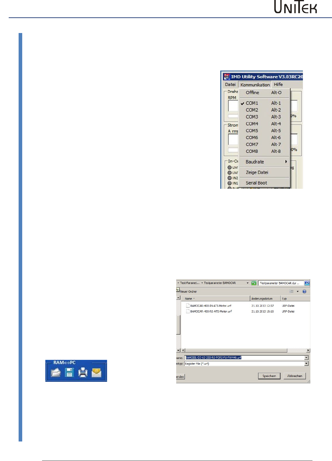
File Features
Load register
NDrive file*.urf
Loading of the parameter file from the pc to the
unit
Save register
NDrive file*.urf
Saving of the parameter from the unit to the pc file
Import register file (*.utd.)
DRIVE file*.utd
Loading of an old (utd) parameter file from the pc to
the unit
Print register
NDrive file
Printing of selected parameters (registers)
Print selected registers
Selected files
Printing of selected parameters (registers)
Script execution
(for service only)
Load protected parameters to the unit
Exit
Closing the window
Page - Register
Permanently active display and inut fields
Speed
Numeric speed display in rpm.
Bar graph 0-100 % speed
Current
Numeric current display in Aeff.
Bar graph 0-200% rated current
Inputs / Outputs
Display of the active inputs and outputs
States
Display of the states
Warning
Display of the warnings
Faults
Error display
Test
Current
Torque
Speed
Position
Only for test operation!!
Numerical entry for a test current
Numerical entry for a test torque
Numeric entry of a test speed value
Dest: = numeric entry of the position
P(preset) = entry as actual position value and
command value
Calib. = Start of a reference run
Footer: Communication Firmware Axis designation
Start screen
9
Version 2017 / V1
Software – Manual N-Drive 3xx
Operation
3.2 Operation
The PC user interface has a standard WINDOWS format.
Only use whole numbers and write decimals with a point.
Write positive values without a sign, negative values with a -sign.
Offline operation
There is no connection to the control unit (servo amplifier). The message ‘Drive is offline’ flashes
in the bottom line of the frame display.
To download a parameter file click → communication → view file and use the windows browser
to select and open a file (*.urf).
The parameter data are transferred to the input fields.
The data can now be optimised and saved again with → file → save register. The original file may
be overwritten or a new file created.
Online operation
Plug the connecting cable RS232. Switch on the PC and the control unit.
Select the baud rate of 115200.
Select the communication interface with → communication → COM1 to COM8.
When the connection is successful, the message ‘Drive is online’ appears in the bottom frame
line.
The active drive parameter data will be imported from the drive to the PC and can be
manipulated via the input fields as required.
Any changed data will be downloaded from the PC to the RAM of the drive by clicking → enter.
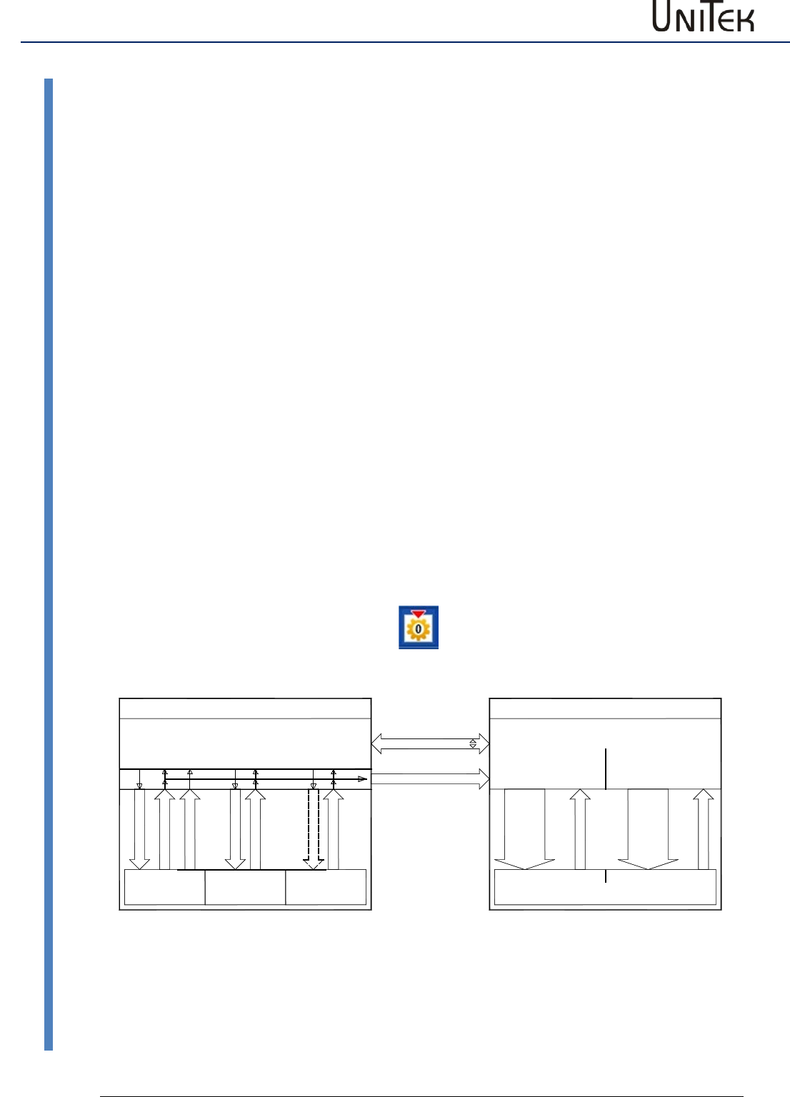
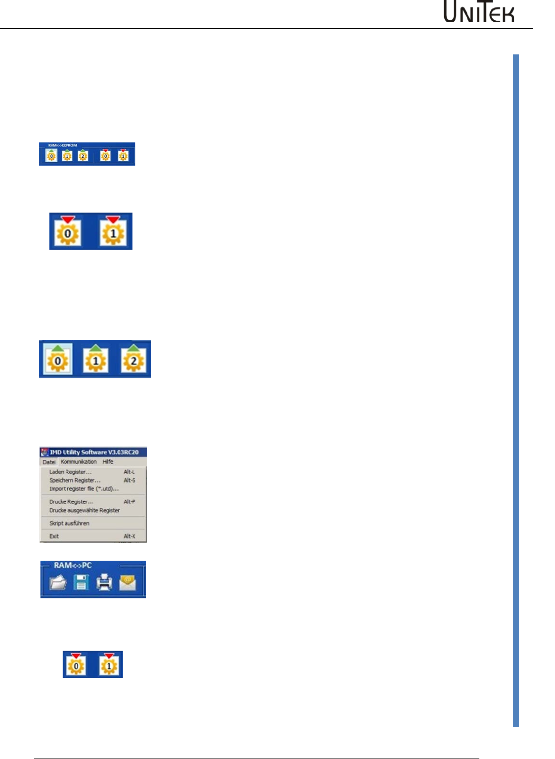
Tested parameters are permanently saved in the EEPROM by clicking the key field ‘memory
level0.1’.
Schreibe 0
Lese 0
Schreibe 1
Schreibe 2
Lese 1
24V-einschalten
Lese 2
Return-Taste auf/ab
Lese 0 - Lese 1 - Lese 2
RAM
EEPROM 0 EEPROM 1 EEPROM 2
Aktiv Kunden-Reserve
Parameter Daten
Oszilloskop
Step-Einstellung
Datei xx.urf Datei xx.uof
PC NDrive - Software
RAM
Open
Save
Save As
Fabrikeinstellung Festplatte
Save
Save As
Open
*.urf *.uof
Servo-Drive DS.., BAMO-D.., BAMOBIL..
Start screen
Software – Manual N-Drive 3xx
Version 2017 / V1
10
Entry and selection
3.3 Entry and selection
Click the entry field (left mouse button),
enter a numerical value and click → enter to save the new value
into the PC RAM and the Drive RAM.
Up-Down value change
Click an input field (left mouse button).
The value can be changed via the up and down buttons.
The values are immediately updated in both device RAMs
Drop-down menu
Click the arrow button of the list box. The menu shows the
available options. Scroll up or down by means of the arrow button
and select an option. Selecting an option updates the variable and
closes the option menu
Option buttons
Click button. The green button displays the selected function.
A tick in the button shows the selected option.
Help
11
Version 2017 / V1
Software – Manual N-Drive 3xx
Direct help
4 Help
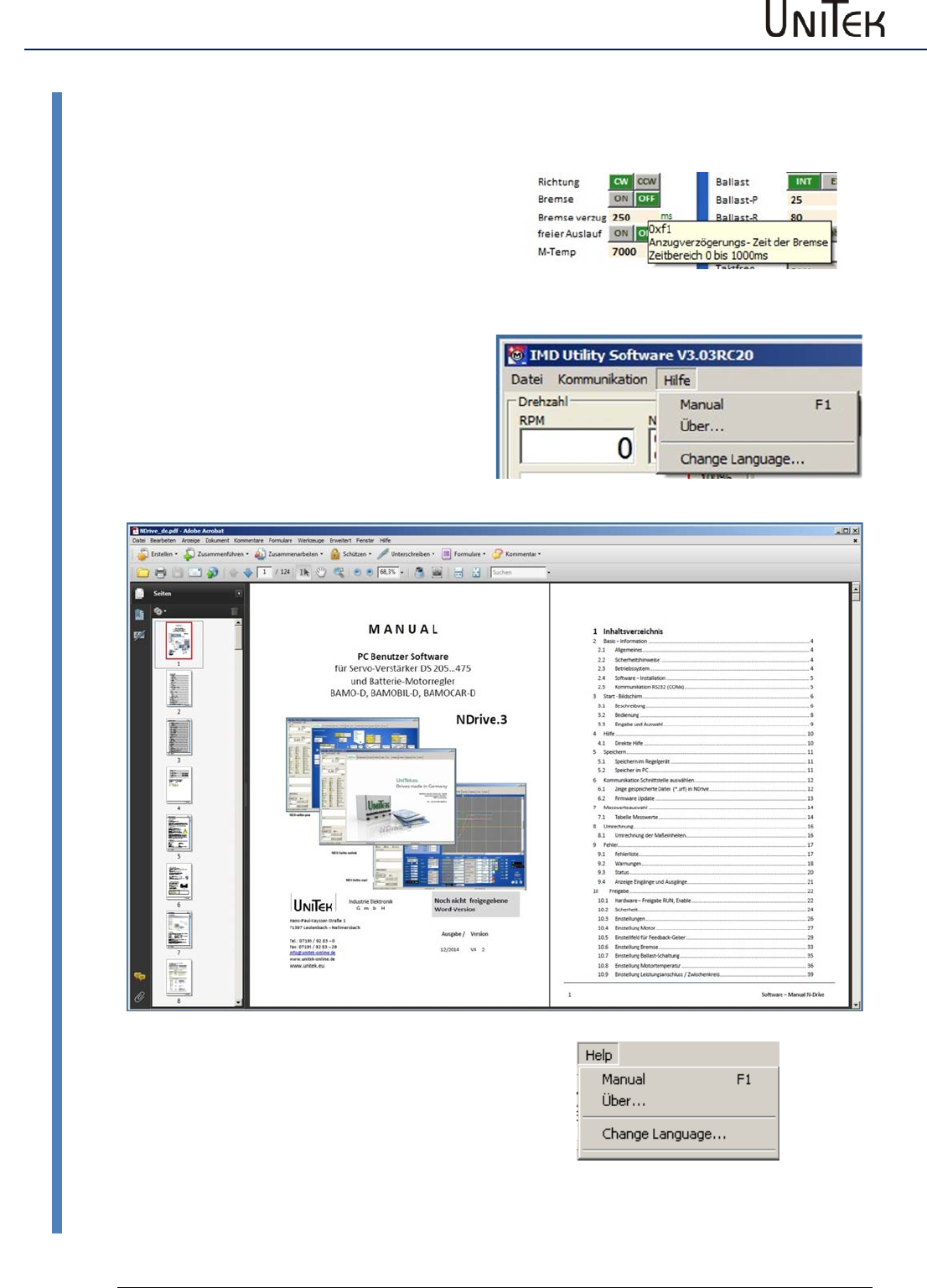
4.1 Direct help
Shift the cursor to the parameter entry field or
setup field and an explanation field opens.
An explanation field opens.
Hilfe-tooltip
Help menu
Click Help.
Click Manual.
A pdf version of the manual Manual NDrive is
opened. Clicking the topic in the bookmark
opens the requested page.
Select language
Click Help
Click ChangeLanguage
A list box opens
Select the language
Restart NDrive
Storage
Software – Manual N-Drive 3xx
Version 2017 / V1
12
Storage in the controller
5 Storage
5.1 Storage in the controller
Download of parameter data from a PC to the controller (servo) RAM (volatile)
When there is an active communication the parameters displayed on the
screen are those currently active in the drive RAM. When a value is changed,
the value is directly updated in the drive RAM when the return key is
pressed.
Attention: If the +24 V auxiliary voltage is switched off, the RAM data will be
lost.
write / save
EEPROM (non-volatile)
Click → write0 (1) on the setting page.
The data are written into the drive EEPROM (level 0, 1).
The EEPROM level 0 contains the current parameter record which is
downloaded to the drive RAM each time when the 24 V auxiliary voltage is
switched on.
Note:
The data EEPROM level 2 is code protected and not visible. It is only visible with the release code.
The data of Write2 are write-protected and contain the factory-set parameter set.
Transfer of parameter data from the drive (servo) to the PC
read / load
Click → read0 (1, 2) on the setting page.
The parameter data are transferred from the drive EEPROM to the drive RAM
and from the drive RAM to the PC RAM
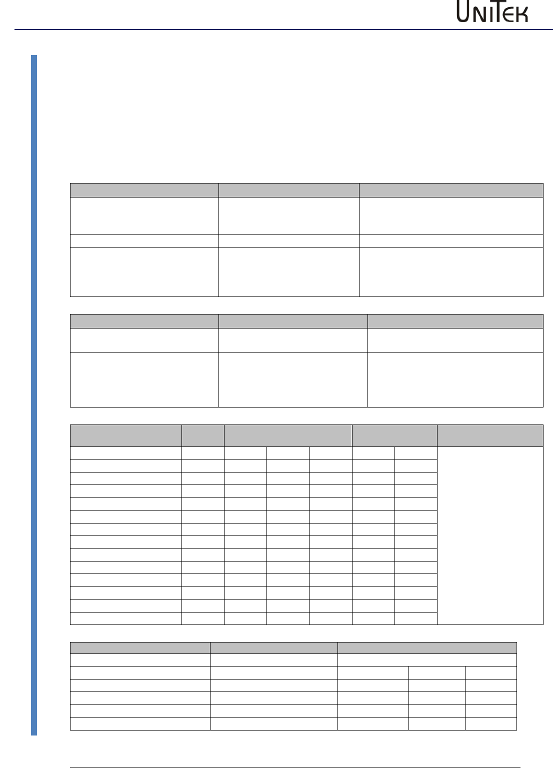
5.2 Storage to the pc
Saving the parameter data of the PC RAM to PC disks (hard drive, CD, floppy
disk, etc.)
Saving parameter data in the PC (*.urf)
- via the menu bar
Click → file in the menu bar.
Click → save registers and the window is opened. Select the required folder
and save with the same or a different file name.
read / load
Through the button save
Click → save on the setting page.
The window save register file is opened. Select the required folder and save
with the same or a different file name
Transfer of parameter data from PC discs (hard drive, CD, floppy disk, etc.) to
the PC RAM
Click → download on the setting page and the window download register file
is opened.
Select the requested folder and click → open to download the data to the
NDrive
The parameters are in the RAM. In order to store them permanently, click →
write 0 or write 1 (EEPROM).
Selection of the communication interface
13
Version 2017 / V1
Software – Manual N-Drive 3xx
Display of a saved file (*.urf) in the NDrive
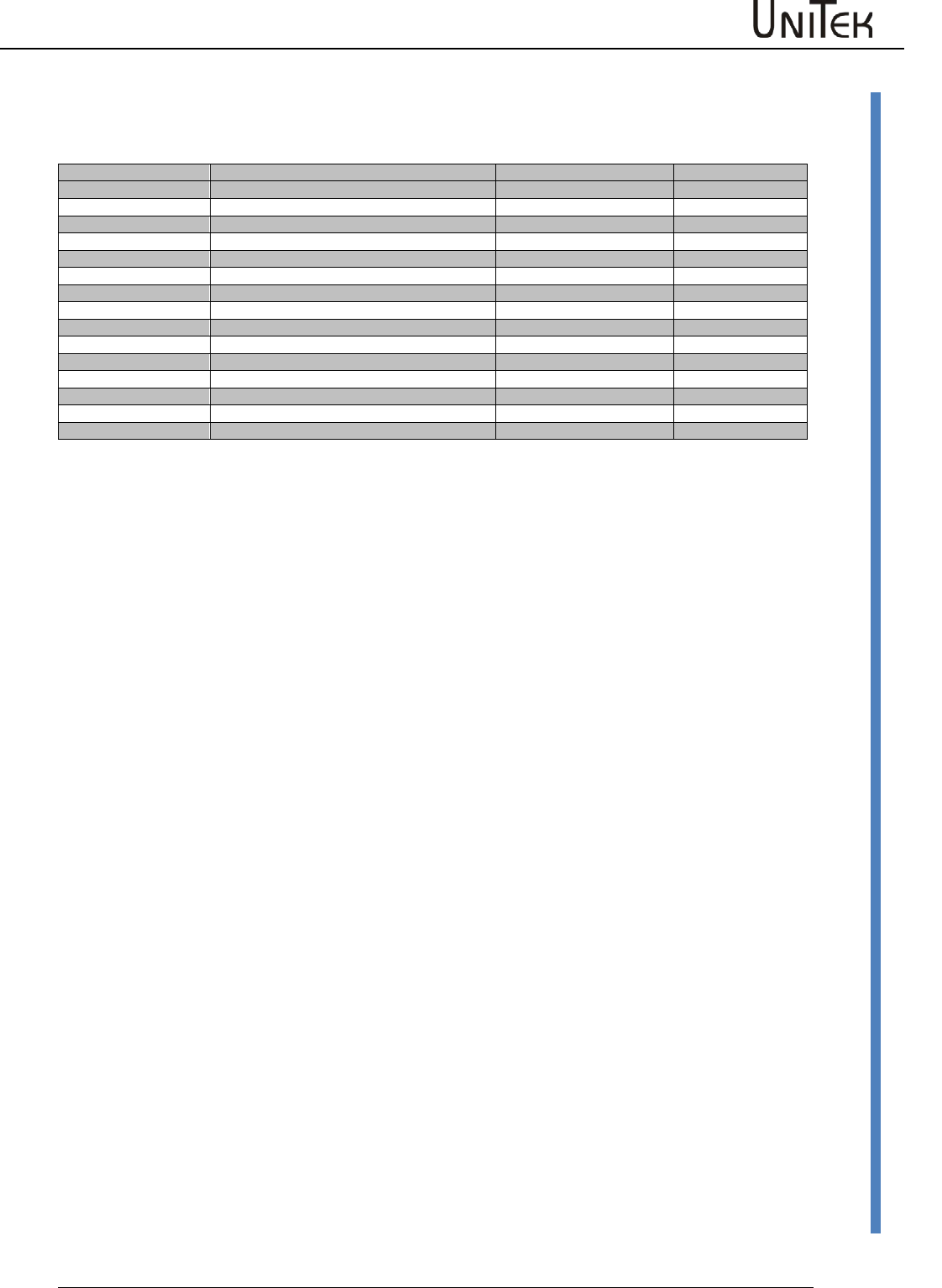
6 Selection of the communication interface
- for online operation
Click the menu → communication to drop down the options.
Click the requested COMx interface (Com1 to Com8) to select
it. The checked interface is selected and the connection to the
control unit (servo) is established.
The message Drive is Online (COMx) is displayed in the bottom
screen frame.
Note:
If the data scroll in the warning or error display, the COM
connection is faulty.
Stop communication
Open drop down menu Kommunikation.
Click →Offline .
The connection is cut off and the message Drive is offline is displayed in the bottom screen frame.
6.1 Display of a saved file (*.urf) in the NDrive
Click ‘view file‘.
The window ‘load register file’ opens.
Select folder.
File is loaded to the NDrive.
The parameter fields are overwritten.
The parameter data can be changed.
Save the modified and checked values with
the same or a new name (*.urf) in the pc via
‘save file register‘.

Selection of the communication interface
Software – Manual N-Drive 3xx
Version 2017 / V1
14
Firmware update
6.2 Firmware update
Please use the manual “Firmware update-2017-SD-Flash_EN.pdf.
Then you will have an update version. The latest manual can either
Manual:
be found on the UniTek CD
UNITEK-CD-DOKU-SOFT
Folder “SOFTWARE\NDrive2-Software\Firmware update inst”
or downloaded from our homepage
www.unitek.eu or www.unitek-online.de
Destination Download
Download NDrive2-Software.zip Press “NDrive2-Software.zip” and save on PC
(e.g. Downloads)
Extract NDrive2-Software.zip Press RM + (Extract All… / Extract Here)
Open folder “NDrive2-Software/Firmware update inst”

Measured values
15
Version 2017 / V1
Software – Manual N-Drive 3xx
Table of measured values
7 Measured values
7.1 Table of measured values
Measured values
Selected values
Function
Range
ID address
OFF
No measured value
REGID
N cmd
Speed command value before ramp
+/- 32767
0x31
N cmd Ramp
Speed command value after ramp
+/- 32767
0x32
N actual
Speed actual value
+/- 32767
0x30
N actual-filter
Filtered speed actual value for display
+/- 32767
0xa8
N error
Speed command/actual value error
+/- 32767
0x33
I cmd
Current command value
see table
0x26
I cmd Ramp
Current command value after ramp
see table
0x22
I actual
Actual current(I)
see table
0x20
I actual-Filter
Filtered current actual value for display
see table
0x5f
Leistung
Motor power
0xf6
Pos dest
Position target
+/- 2147483647
0x6e
Pos cmd
Position command value
+/- 2147483647
0x91
Pos actual
Actual position
+/- 2147483647
0x6d
Pos error
Position command/actual value error
+/- 32767
0x70
Zero capture
0x74
I_Limit1
Digital input END1
0/1
0xe4
I_Limit2
Digital input END2
0/1
0xe5
I_Din1
Digital input 1
0/1
0xe6
I_Din2
Digital input 2
0/1
0xe7
I_Run (Frg)
Digital input control unit enable
0/1
0xe8
O_Dout1
Digital output 1
0/1
0xe0
O_Dout2
Digital output 2
0/1
0xe1
O_Dout3
Digital output 3
0/1
0xe1
O_Dout4
Digital output 4
0/1
0xe1
O_Rdy (BTB)
Drive ready message
0/1
0xe2
I_Fault
Intern. error message from the power section
0/1
0xe9
I_Regen (Ballast)
Ballast circuitry state
0/1
0xea
I_o´/u´ voltage
Over-voltage condition
0/1
0xeb
I_LossOfSignal
Resolver signal missing or faulty
0/1
0xec
O_Go
Internal enable
0/10/1
0xe3
O_Brake
Active brake
0/1
0xf2
O_Icns
Limited to continuous current
0/1
0xf3
O_Less_NO
Speed inferior to 0.1%
0/1
0xf5
O_Toler
Within position tolerance range
0/1
0xf4
Rotor
Rotor position signals (RST)
1 to 6 (0 or 7 = error
0x5c
Var1
Comparison reference value 1
+/-32767
0xd1
Var2
Comparison reference value 2
+/-32767
0xd2
Var3
Comparison reference value 3
+/-32767
0xd3
Var4
Comparison reference value 4
+/-32767
0xd4
MPOS_mech
Mechanical rotor position
0x42
MPOS_elec
Electrical motor position
0x43
Ain1
Analog input Ain1
+/-32767
0xd5
Ain2
Analog input Ain2
+/-32767
0xd6
I3_adc
Current actual value sensor 3
2048 +/- 2000
0xa9
I2_adc
Current actual value sensor 2
2048 +/- 2000
0xaa
I1_actual
Current actual value Ph1
see table
0x54
I2_actual
Current actual value Ph2
see table
0x55
I3_actual
Current actual value Ph3
see table
0x56
Iq_actual
Current actual value
0-600
0x27
Id_actual
Current actual value
0-600
0x28
Iq_error
Current actual value - command/actual val. error
0-600
0x38
Id-error
Current actual value - command/actual val. error
0-600
0x39
Idnom
0xb2
Idmin
0xb5
Ilim_inuse
0x48
DC-BUS
Bus voltage
0-32767
0xeb
Vd
Voltage
0x2a
Vq
Voltage
0x29
Vout
Output voltage
0x8a
Measured values
Software – Manual N-Drive 3xx
Version 2017 / V1
16
Table / measured value
7.2 Table / measured value
Measured values
Selected values
Function
Range
ID address
Vred
Voltage limitation
0x8b
pwm1 (5/6)
Pulse width modulation phase 1
750 +/-750
0xac
pwm2 (3/4)
Pulse width modulation phase 2
750 +/-750
0xad
pwm3 (1/2)
Pulse width modulation phase 3
750 +/-750
0xae
T_Motor
Motor temperature
0-32767
0x49
T_IGBT
Output stage temperature
0-32767
0x4a
T_air
Air temperature (unit interior)
0-32767
0x4b
Ballast Count
Ballast power monitoring
0xa1
Temp-Debug
For service only
0x9a
Logic (Hz)
I/O processing frequency
0-32767
0xab
Time_1us
Time pulse 1us
1/0
0x98
*PTR1
0xb8
*PTR2
0xba
Unknown
Conversion
17
Version 2017 / V1
Software – Manual N-Drive 3xx
Conversion of the measurement units
8 Conversion
8.1 Conversion of the measurement units
For position, speed, current, and command value
Some of the measured values are not converted in all formats. Numeric values (num) are indicated and
processed. It must be differentiated between the values and their numeric representation when processing
data such as in case of data transfers (CAN-BUS, RS232) or track and oscilloscope displays.
Position
Actual position range
Resolver
Incremental encoder
Pulses/rpm
Max. value +/-2147483647
(31 Bit-1)
65536
65536
Resolution (lowest value)
16 (65536/4096 (12Bit))
65536/Ink x4
Example
Feed Drive
Factor 5mm/rpm
Travel 1000mm = 200 rpm
200 rpm = 13107200
Resolution = 65536/4096 = 16
Incremental encoder 2048 pulses/rpm
Travel 1000mm = 200rpm
200 rpm = 1638400
Resolution 65536/8192 = 8
Speed
Actual speed range
Max. speed (Nmax) calibration
Limitation
Max. value +/- 32767 (15Bit-1)
Nmax value in the parameter
field Motor and speed = 32767
Speed limiting via the parameter field
'speed limit'
Example
N max = 2000
Speed of 2000 rpm corresponds
to 32767
The max. speed is limited to 1500 rpm.
Limit = 32767/2000*1500 = 24575 num
Die maximale Drehzahl ist auf 1500
Upm begrenzt
Current
I 100 %
Rated current (I) calibration
I-device
Peak current (I)
DC disabled
Limitation
Max. value +/- 9bit
mV
Num
Aeff
A=
Num
A=
Limit set in the
parameter fields Motor
and Current.
The smallest value is
valid.
DS 205/405
550
440
5
7
640
10
DS412
800
640
12
17
920
24
DS420
700
560
20
28
800
40
DS450
416
328
50
70
480
100
DS475 / BAMO-D3
416
328
75
105
480
150
BAMOBIL-D3-50/250
870
700
25/125
35/175
1020
50/250
BAMOBIL-D3-80
560
450
40
56
650
80
BAMOBIL-D3-100
700
560
50
60
800
100
BAMOBIL-D3-120
840
670
60
84
970
120
BAMOBIL-D3-350
610
490
175
245
710
350
BAMOBIL-D3-450
785
630
225
315
910
450
BAMOCAR-D3-250
625
700
125
176
1020
250
BAMOCAR-D3-400
500
560
200
282
810
400
Command values
Position command value range
Speed command value range
Current command value range
Max. value +/-31Bit
Max. value +/-15 Bit
Max. value +/- 9Bit
+/- 2147483647 Num
+/- 32767 Num
DS 205/405
rated: 440
max: 640
DS 412
rated: 640
max: 920
DS 420
rated: 560
max: 800
DS 450
rated: 328
max: 480
DS 475/BAMO
rated: 328
max: 480
Errors
Software – Manual N-Drive 3xx
Version 2017 / V1
18
Error list
9 Errors
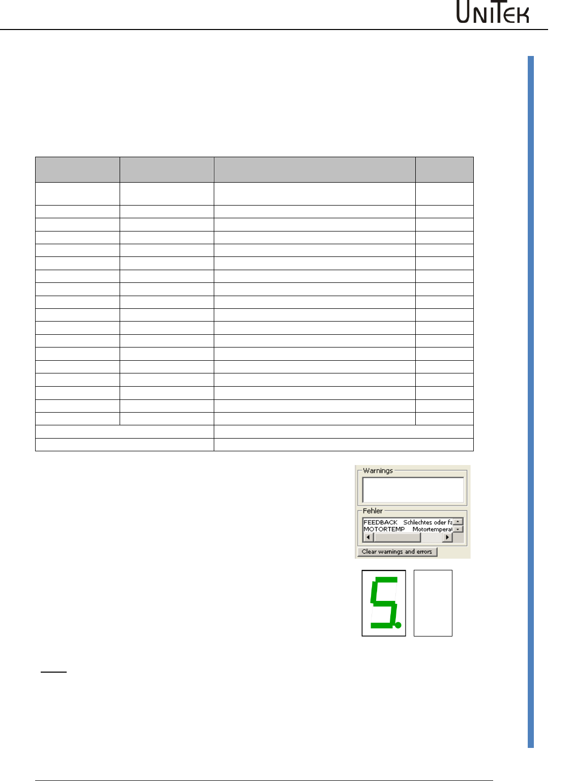
The error messages are displayed in the window 'Error'.
9.1 Error list
LED displays on the servo
In case of an error the red LED ‘fault’ lights up and the error no.
is indicated.
The BTB (ready) contact is opened.
The software ‚BTB message‘ switches from 1 to 0.
The state message ‚RDY‘ extinguishes.
When the enable is switched off, the error message is still
displayed.
The error message deleted:
When the enable is switched on, the function ‘cancel errors’ is
activated via a digital input or a CAN BUS.
Note:
When applying the 24V auxiliary voltage with the enable closed (FRG/RUN X1:7 aktiv) the red LED
signals an error. There is no fault signal displayed in the 7-segment display.
Display on the
servo
Error message
on the NDrive
Description
NOREPLY-NORS
RS232 failure.
Incorrectly connected or missing connecting cable
0
BADPARAS
Defective parameter
1
POWER FAULT
Output stage fault
2
RFE FAULT
Faulty safety circuit (only active for RUN)
3
BUS TIMEOUT
Transfer fault BUS
4
FEEDBACK
Faulty encoder signal
5
POWERVOLTAGE
No power supply voltage
6
MOTORTEMP
Motor temperature too high
7
DEVICETEMP
Device temperature too high
8
OVERVOLTAGE
Overvoltage >1.8 x UN
9
I_PEAK
Over-current 300 %
A
RACEAWAY
Racing (no command value, incorrect polarity)
B
USER
User – error selection
C
I2R
Bleeder resistor
D
HW_FAIL
Firmware not compatible with hardware
E
ADC-INT
Current measuring fault
F (device dependent)
BALLAST
Ballast circuit overload
Flashing decimal point
Active processor
Dark decimal point
No auxiliary voltage or unit-internal hardware fault
FAULT
Errors
19
Version 2017 / V1
Software – Manual N-Drive 3xx
Warnings
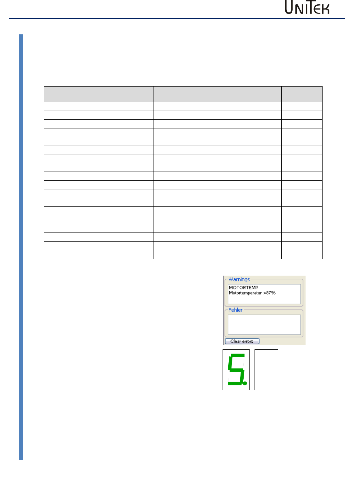
9.2 Warnings
Display of the warning messages.
The warning messages are displayed in the window 'warnings'.
Display on
the servo
Error message
on the NDrive
Description
ID address
REGID 0x8f
0
WARNING_0
Inconsistent device identification
Bit 16
1
ILLEGAL STATUS
Faulty RUN signal, EMI
Bit 17
2
WARNING_2
Inactive RFE signal (without RUN)
Bit 18
3
Bit 19
4
Bit 20
5
POWERVOLTAGE
Power voltage missing or too low
Bit 21
6
MOTORTEMP
Motor temperature > 87 %
Bit 22
7
DEVICETEMP
Device temperature > 87 %
Bit 23
8
OVERVOLTAGE
Overvoltage >1.5 x UN
Bit 24
9
I_PEAK
Over-current 200 %
Bit 25
A
Bit 26
B
Bit 27
C
I2R
Overload > 87 %
Bit 28
D
Bit 29
E
Bit 30
F
BALLAST (device dependent)
Ballast circuit overload > 87 %
Bit 31
LED desplays on the servo
In case of warning state the red LED changes (low-
frequency) and the seven-segment display shows alternately
the warning no. (red LED) and the operating state (LED
dark).
FAULT
Errors
Software – Manual N-Drive 3xx
Version 2017 / V1
20
Warnings
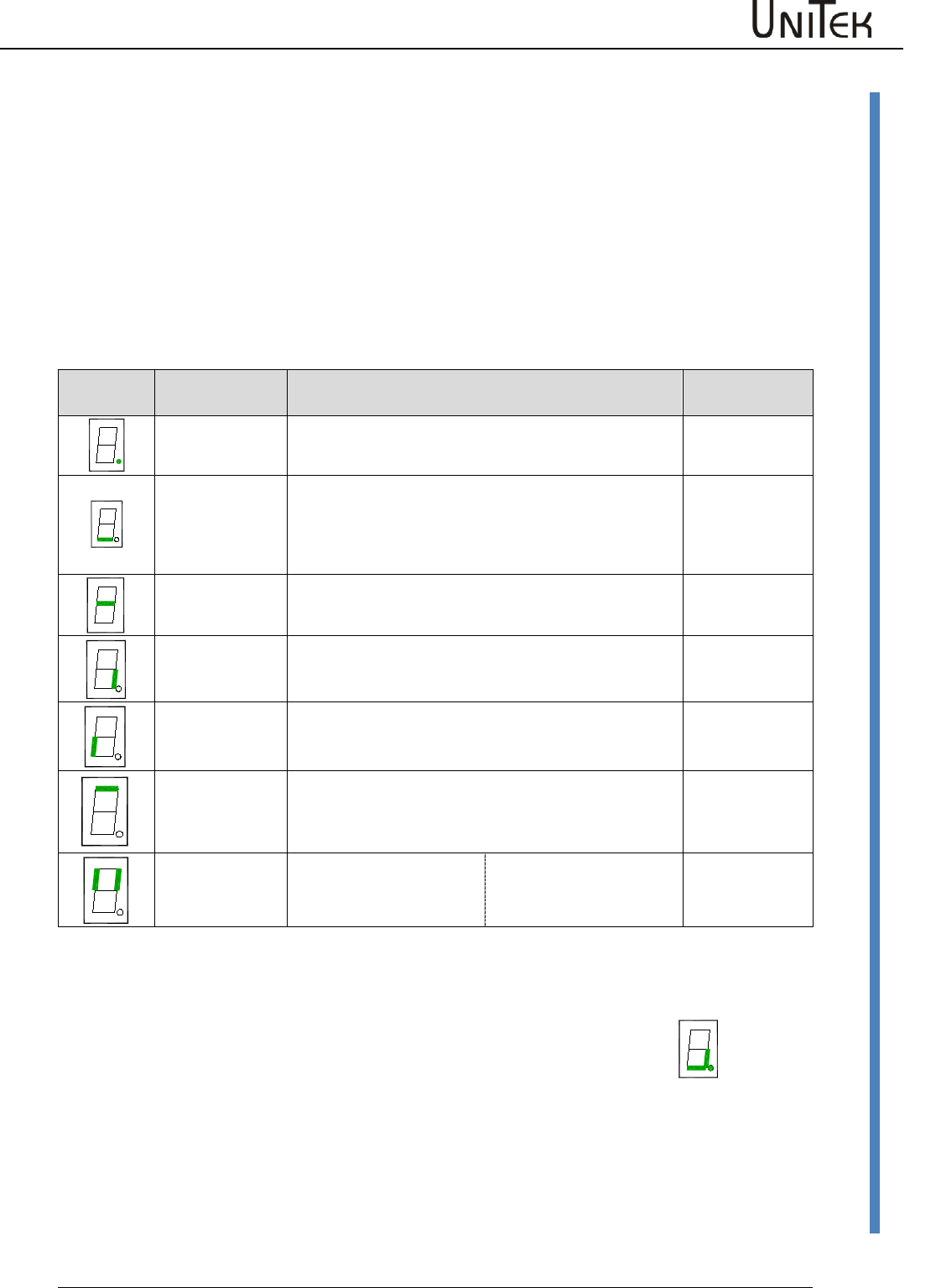
LED display on the servo
The operating state "normal" is signalled by a bright green seven-segment display + decimal point
(display of the state).
The state "fault" is signalled by a bright red fault LED and the seven-segment display indicates the
error no.
In case of a “warning” state the red LED changes and the segment display shows alternately the
warning no. and the state.
Display of the servo-drive state
Display
Point/segment
State
State of
NDrive
flashing
dark
Processor active
Auxiliary voltage missing or inherent hardware failure
flashing
bright
dark
Starting state after reset (aux. voltage 24V off-on). The first enable
stops the flashing display.
Drive enabled
Drive disabled (not enabled)
OK = 0
OK = 1, ENA = 1
OK = 1, ENA = 0
bright
Speed zero (standstill signal) NO = 1
bright
Drive revolves clockwise, N currently positive NO = 0
bright
Drive revolves anti-clockwise, N currently negative NO = 0
flashing
bright
dark
Motor current reduced to continuous current Icns
Motor current at max. current limit Imax
Normal operation; Motor current within the current limits
lcns = 1
lcns = 0
lcns = 0
bright for 0.1s
Left segment:
Right segment:
A new command (value) was
received from the BUS or RS232
Digital input changed.
Example: Motor revolving clockwise
Point flashes
Bottom segment
Right segment
=
=
=
Processor active
Drive enabled
Motor revolves clockwise
Ballast circuit
switching:
The direction segment (at the right or left bottom) is switched off when the
ballast circuit is switched on.
Errors
21
Version 2017 / V1
Software – Manual N-Drive 3xx
States
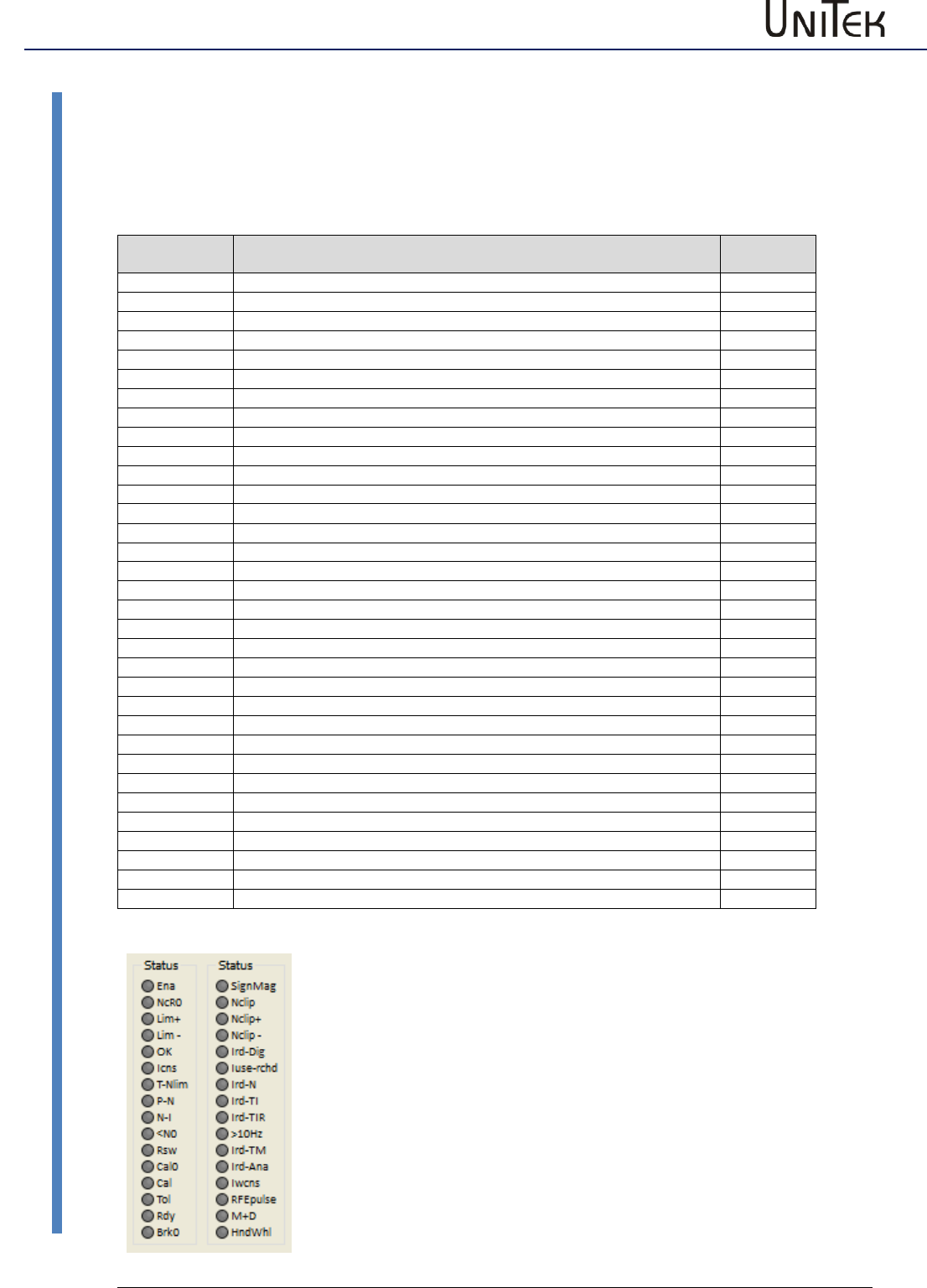
9.3 States
State display
The operating states are displayed in the window 'state'.
List of states
Display of the
state
Function
address
REGID 0x40
Ena
Drive enable (combination hardware RUN and Software)
Bit 0
NcR0
Speed limit to zero (Speed command still active)
Bit 1
Lim+
Limited switch Plus tripped
Bit 2
Lim-
Limited switch Minus tripped
Bit 3
OK
Drive okay (no uncontrolled control-voltage reset seen)
Bit 4
Icns
Current is limited to the continuous current level
Bit 5
T-Nlim
Speed limited torque mode active
Bit 6
P-N
Position control possible
Bit 7
N-I
Speed control possible
Bit 8
<N0
Actual speed less than 0.1 %
Bit 9
Rsw
Reference switch tripped
Bit 10
Cal0
Calibration move active
Bit 11
Cal
Calibration move completed (position calibrated)
Bit 12
Tol
Position within tolerance window
Bit 13
Rdy
Drive ready (BTB/RDY contact is closed)
Bit 14
Brk0
De-energized brake with motor active
Bit 15
SignMag
Speed internally inverted
Bit 16
Nclip
General speed limiting (if ≤ 90%) possible
Bit 17
Nclip+
Additional switchable positive speed limiting possible
Bit 18
Nclip-
Additional switchable negative speed limiting possible
Bit 19
lrd-Dig
Current limiting (switchable) reached
Bit 20
luse-rchd
Actual current limit reached
Bit 21
lrd-N
Current limiting (speed)
Bit 22
Ird-TI
Current derating (power-stage temperature) possible
Bit 23
Ird-TIR
Current reduced to continuous current (power-stage temperature )
Bit 24
>10 Hz
Additional current limit if frequency less than 10 Hz
Bit 25
Ird-TM
Current limiting due to motor temperature reached
Bit 26
Ird-ANA
Current derating due to analog input (if ≤90 %) possible
Bit 27
lwcns
Current peak value warning
Bit 28
RFE pulse
Pulsed RFE –input monitoring active
Bit 29
M+D
vacant
Bit 30
HndWhl
Hand-wheel function selected
Bit 31
Errors
Software – Manual N-Drive 3xx
Version 2017 / V1
22
Display of inputs and outputs
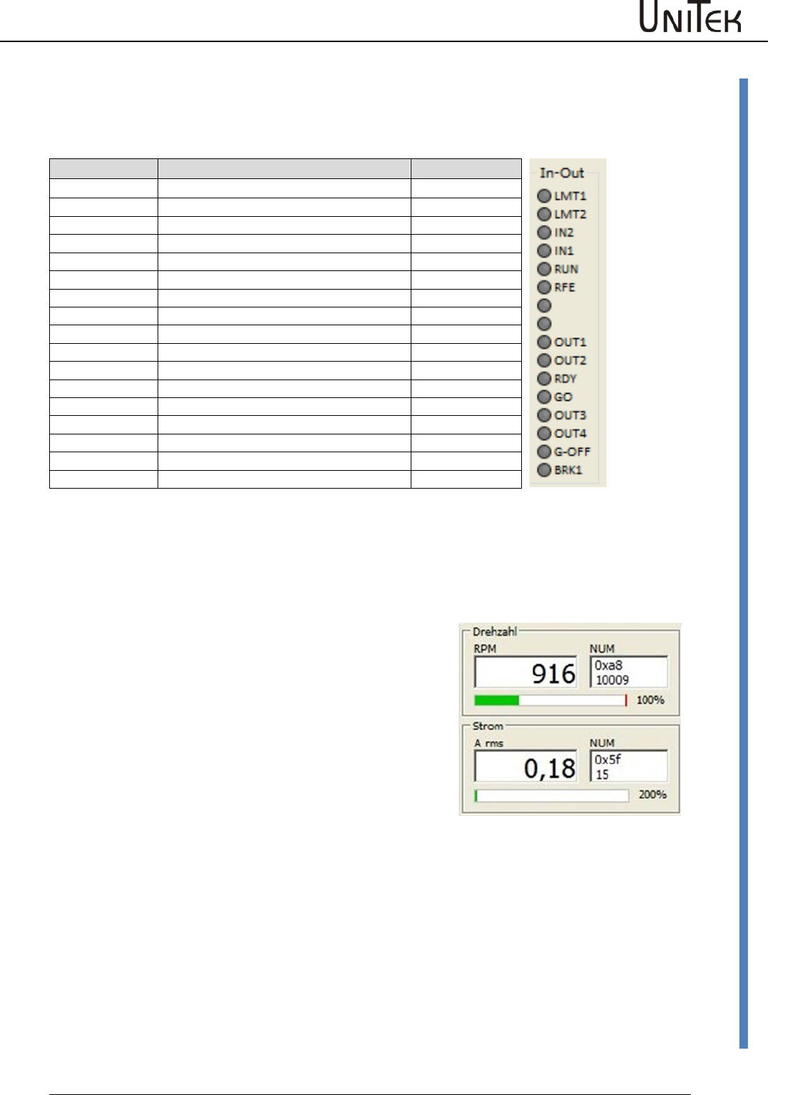
9.4 Display of inputs and outputs
The LEDs are bright when the positive input voltage is superior to >10 V and the output voltage is
positive
Short symbol
Function
ID-Ad.
REGID 0xd8
LMT 1
Digital input limit 1 active
Bit 0
LMT 2
Digital input limit 2 active
Bit 1
IN 2
Digital input Din 2 active
Bit 2
IN 1
Digital input Din 1 active
Bit 3
FRG (RUN)
Hardware enable active
Bit 4
RFE
Rotating field enable
Bit 5
Bit 6
Bit 7
OUT 1
Digital output Dout 1 on
Bit 8
OUT2
Digital output Dout 2 on
Bit 9
BTB (Rdy)
Hardware relay, output BTB (Rdy) on
Bit 10
GO
Internal enable GO active
Bit 11
OUT 3
Digital output Dout 3 on
Bit 12
OUT 4
Digital output Dout 4 on
Bit 13
G-OFF
Bit 14
BRK1
Excited brake
Bit 15
Display of speed and current
Speed in rpm (revolutions per minute) and as numerical
value from the parameter 0xa8
Current in Aeff (motor current in ampere effective / rms)
and as numerical value from the parameter 0x5f
Enable
23
Version 2017 / V1
Software – Manual N-Drive 3xx
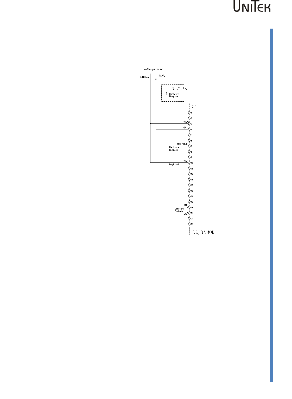
Hardware - Enable FRG/RUN
10 Enable
10.1 Hardware - Enable FRG/RUN
Switching on
Voltage across the enable input (X1:7, X1:G FRG/RUN) > 10 V= , <30 V=
The power stage of the drive is immediately enabled when the drive enable is switched on. The
software control of the power stage is activated 2ms later. Commands such as command values,
reference travel, etc. can be sent 5ms after the drive enable (RUN).
The enable state is indicated in the state field with 'Ena'.
Switching off
Voltage across the enable input (X1:7, X1:G FRG/RUN) < 4 V=
When the enable function is switched off, the drive is electronically
disabled.
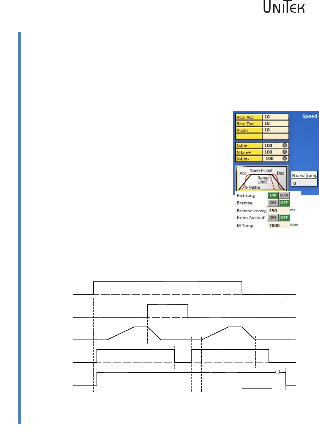
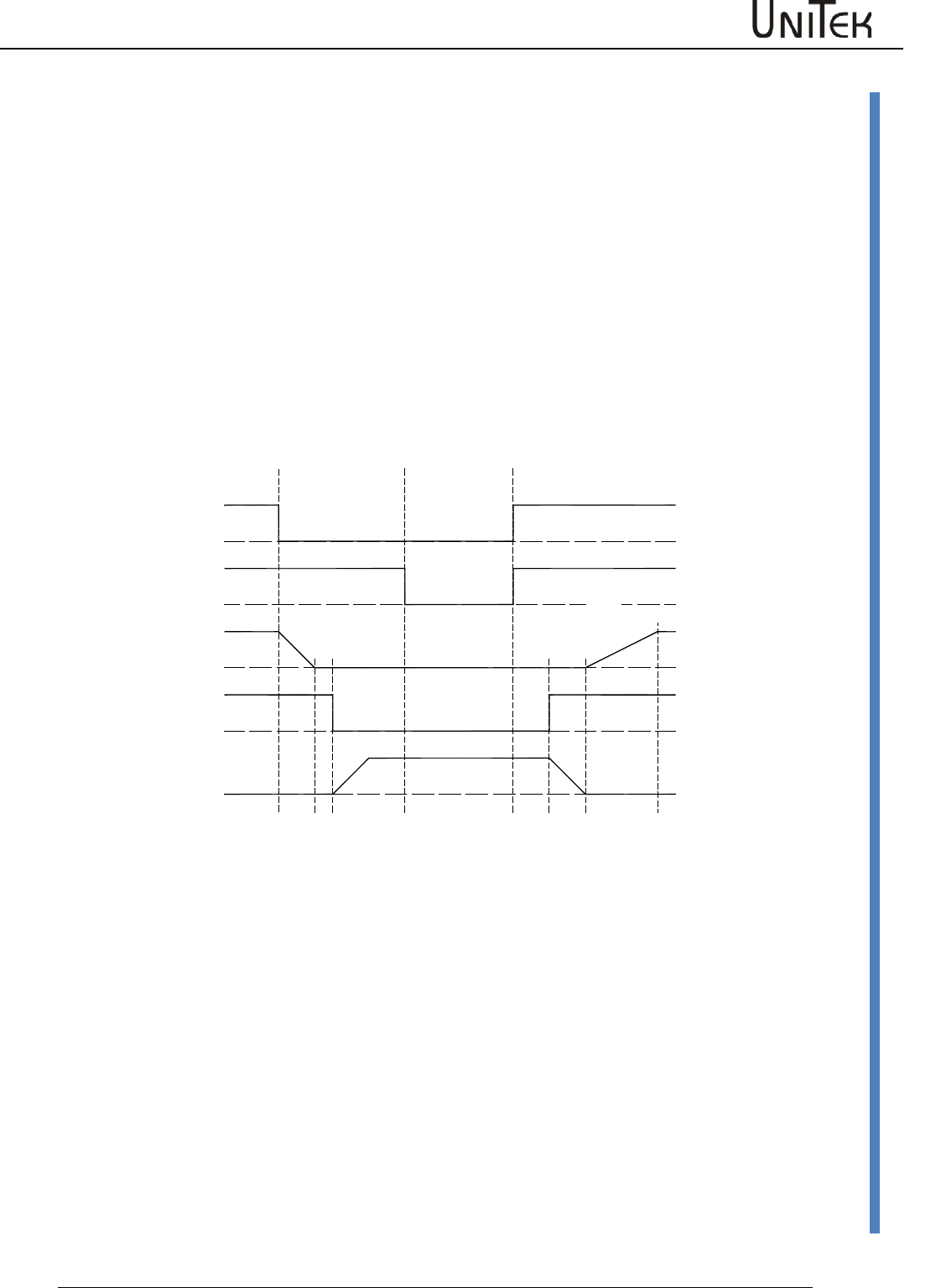
Switching off with emergency stop (free coasting Off)
The drive decelerates to standstill before it is enabled.
When the enable function is switched off, the internal speed command
value N cmd Ramp is reduced to zero by means of the ramp limit
which has been adjusted in the parameter field speed. The power
section is disabled by means of the internal command GO 50ms after
the axis has come to a standstill or after the ramp time (ramp limit) +
50ms has elapsed.
The power stage is disabled after 1.5 s at the latest.
Switching off without emergency stop (free coasting On)
The power section is immediately disabled when the enable function is switched off.
The drive decelerates free of torque.
GO (intern)
z. B. Sollwert
Ramp-Limit
FRG2 (intern)
Hardware
50ms
1,5s
ENABLE OFF
MODE-BIT 2
Ramp-Limit
50ms
Ramp-Acc Ramp-Acc
2
ms 5
ms ms
5
2
ms
Fahrbefehl
Freigabe (RUN)
Enable
Software – Manual N-Drive 3xx
Version 2017 / V1
24
Hardware - Enable FRG/RUN
Enable and disable function via interfaces (CAN BUS, RS232)
The hardware enable (FRG/RUN) and the safety input must be switched on!
Enable
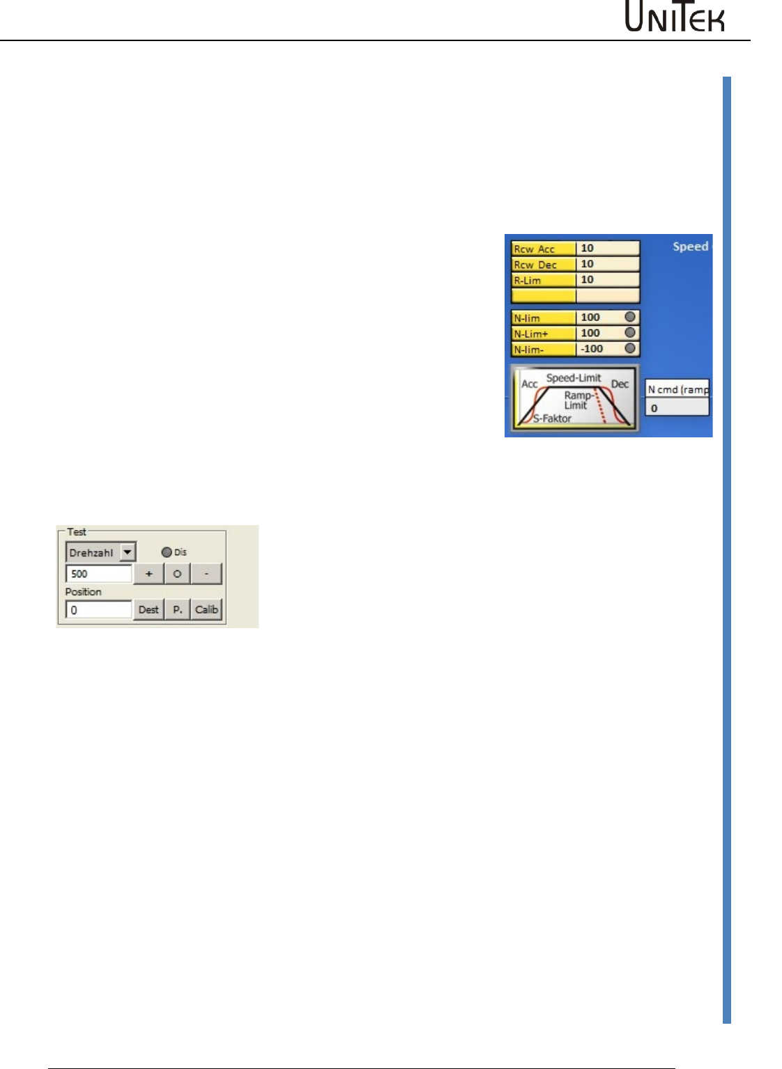
By means of the command ‘Not ENABLE OFF’ (MODE-BIT 0x51 Bit2=0)
the amplifier is enabled without delay.
Disable
By means of the command ‘ENABLE OFF’ (MODE-BIT 0x51 Bit2=1)
the internal speed command value N cmd (ramp) is controlled to zero
according to the ramp R-Lim adjusted in the parameter field ‘speed’.
Set R-Lim in such a way that the drive is braked to a standstill.
50ms after the switch-off ramp time (ramp limit) has elapsed, the
power section is disabled. The drive is torque-free.
Software enable of the NDrive
The hardware enable (FRG/RUN) must be switched on!
Switching field Dis
grey = Software enable = ON
red = Software enable = OFF
Enable
25
Version 2017 / V1
Software – Manual N-Drive 3xx
Safety
10.2 Safety
Safety input RFE (Rotating field enable)
Warning:
If the input of the enable or of the rotating field (FRG/RUN)
enable are switched off, the drive is free (RFE) of torque.
The drive could move if there is no mechanical brake or block
provided.
The motor conductors are not dead. Only the rotating field is
disabled. Prior to any work or maintenance on the motor or
servo-drive, the servo-drive must be completely disconnected
from the mains power supply.
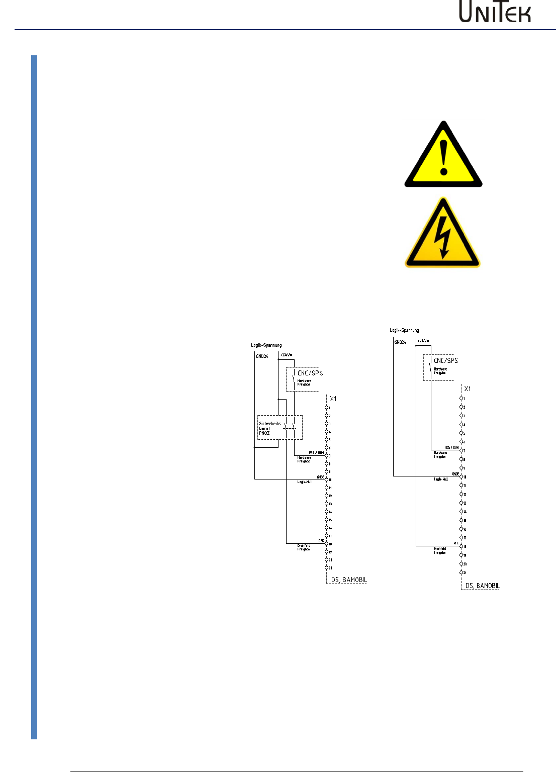
Operation with an RFE input
Two-channel disable of the
enable via a safety switching
device.
Enable input FRG/RUN +
Rotating field enable input RFE.
Switching-on
Contacts of the safety device
closed, enable FRG/RUN 0.5s
after RFE.
Safety switch-off
Contacts of the safety device
open:
- there is no FRG/RUN signal in
the 1st disable channel to disable
the PWM pulses in the processor
-there is no RFE signal in the 2nd
disable channel to disable the
PWM pulses at the output of the
processor
Restart
Release the safety switching
device.
Contacts of the safety device
closed.
The motor can only move after a
second disable FRG/RUN (after
the rotating field enable).
Enable
Software – Manual N-Drive 3xx
Version 2017 / V1
26
Safety
Operation without RFE input
The input RFE must be bridged with the logic
voltage.
If the logic voltage corresponds to the supply
voltage, the RFE input is bridged with +24 V.
Enable FRG/RUN at least 0.5 s after the RFE
signal.
Note:
In case of circular and Tyco connectors
(BAMOCAR,BAMOBIL) use the plug no. of the
device MANUAL.
Enable
27
Version 2017 / V1
Software – Manual N-Drive 3xx
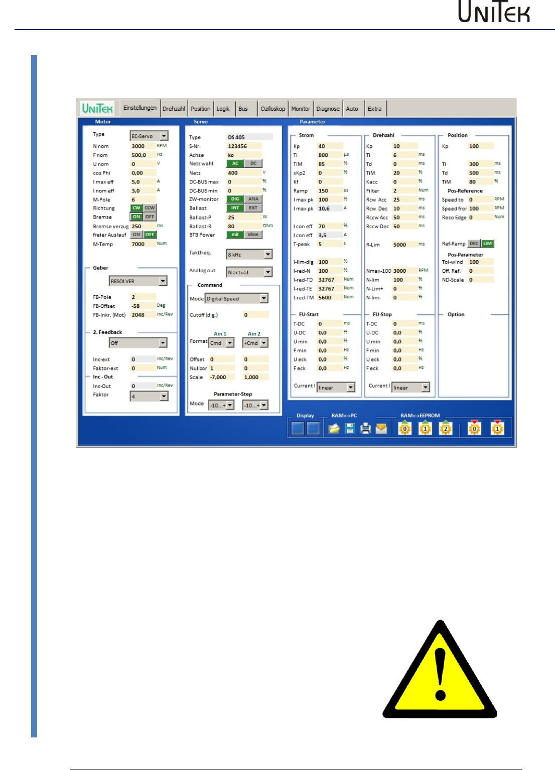
Settings
10.3 Settings
Parameters and data input
Input fields for motor data, device data (servo) and parameter data.
Buttons for the saving functions.
The adjustments for the motor and the servo amplifier can only be made via the setting window.
The parameter data can be entered via this and several other windows. The changed parameter
data are immediately updated on all pages.
When a value has been changed, the new value is automatically updated on all windows.
See the detailed information for the input fields.
Note:
Prior to the first commissioning and any change of the motor
type the data displayed in the setting windows must be
checked with the type plate or the data sheet of the motor.
Please observe the motor specific connection guidelines!
Any changes of the set value during online operation must
only be carried out by competent and qualified personnel.
Enable
Software – Manual N-Drive 3xx
Version 2017 / V1
28
Motor setting
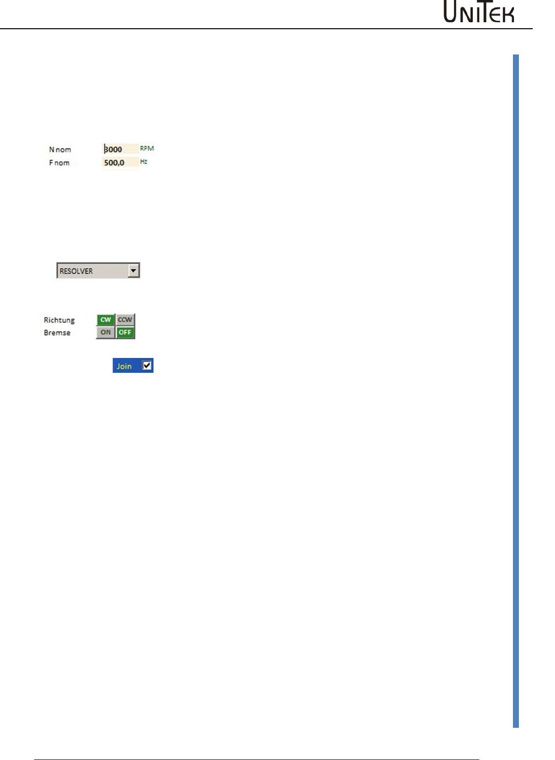
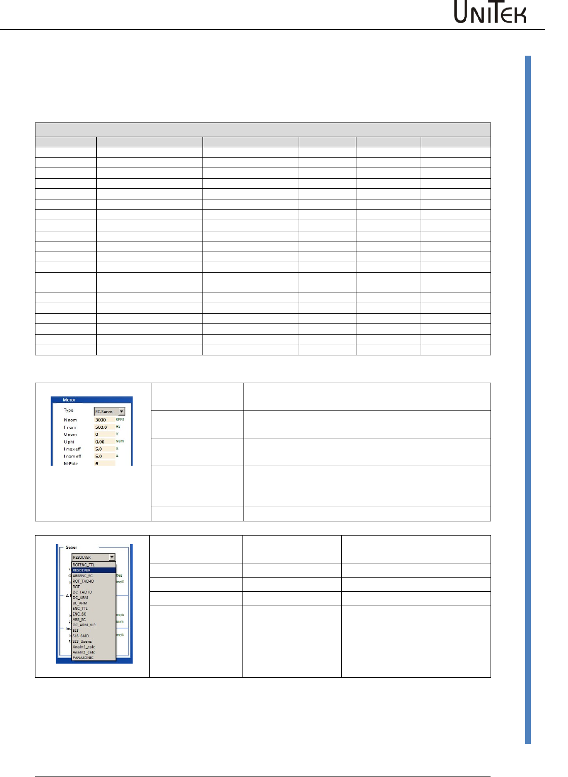
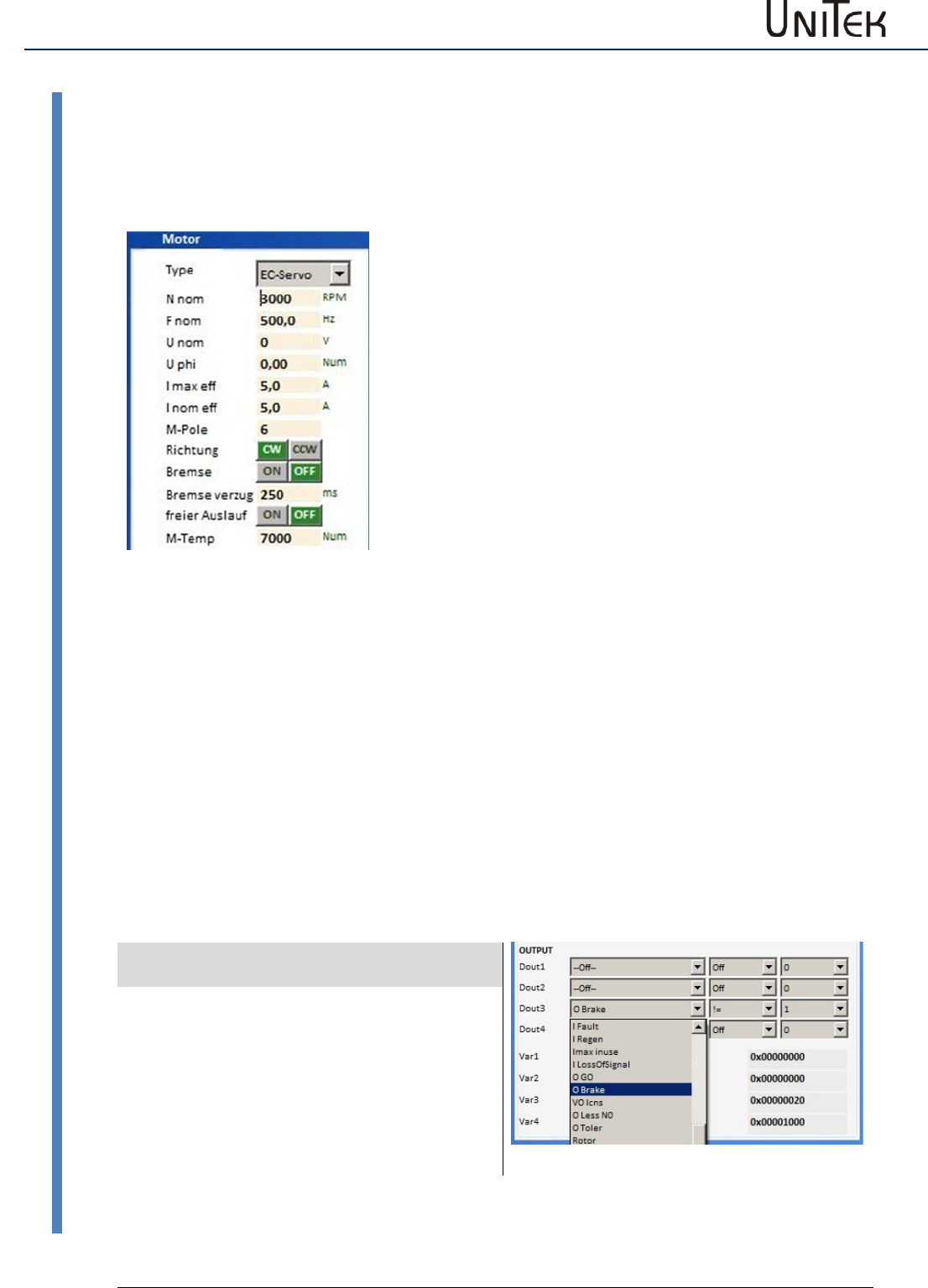
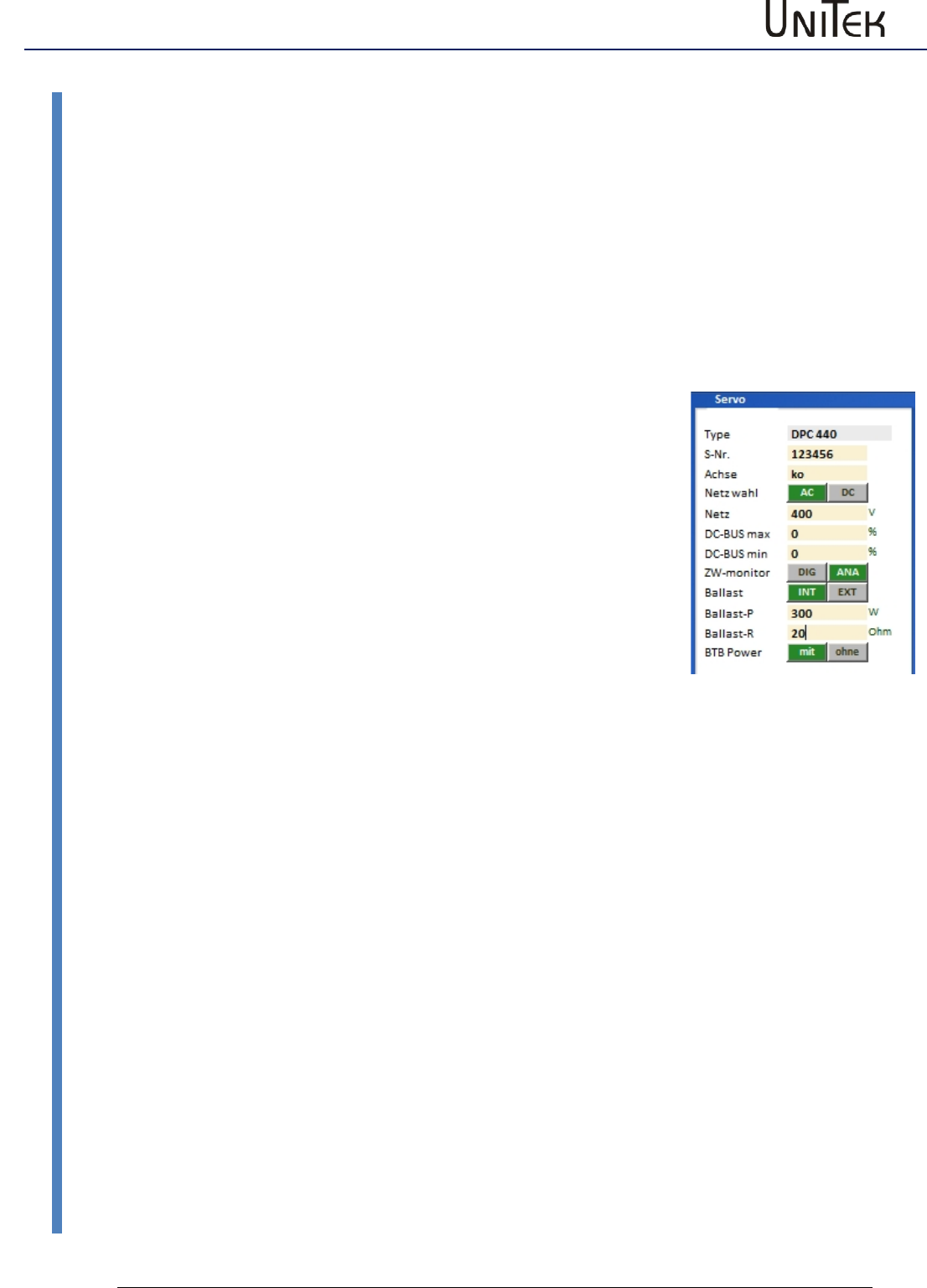
10.4 Motor setting
Setting window for the rated motor data
Motor setting parameters
Short symbol
Function
Setting range
Unit
Note
ID address
Type
Select motor type
Nnom
Rated motor speed
Type plate (600-50000)
rpm
0x59
Fnom
Rated motor frequency
20 bis 1200
Hz
0x05
Unom
Rated motor voltage
Type plate
V
0x06
Uphi
Motor power factor
Type plate
%
0x0e
I max eff
max. motor current(I)
Type plate
A
0x4d
I nom eff
Continuous motor current(I)
Type plate
A
0x4e
M- Pole
No. of motor poles
2..48
Num
0x4f
Direction
Select rotation direction
Switching field
Selection
0x5a-Bit8
Brake
Select with/without brake
Switching field
Selection
0x5a-Bit18
Brake Delay
Response time motor brake
0..500
ms
0xf1
Free coasting
Selection
Switching field
0x5a-Bit3
M-Temp
Switching point motor
temperature
0 to 32767
Num
0xa3
Encoder
Selection of encoder system
Selection
2. Feedback
Selection 2. encoder system
Selection
Inc-Out
Output counter increment
Motor type
selection
Motor type
EC-Servo
Synchronous servo motor with encoder system
(sensor)
FU
Asynchronous motor frequency converter without
sensor
FU-Servo
Asynchronous motor AC servo vector control with
speed encoder system (e.g. position encoder A,B
channel)
DC
DC motor without or with DC tacho encoder
Motor type
selection
Feedback
EC-Servo
Feedback selection
FU
without feedback
FU-Servo
Feedback selection
DC
without feedback
or
DC tacho
Enable
29
Version 2017 / V1
Software – Manual N-Drive 3xx
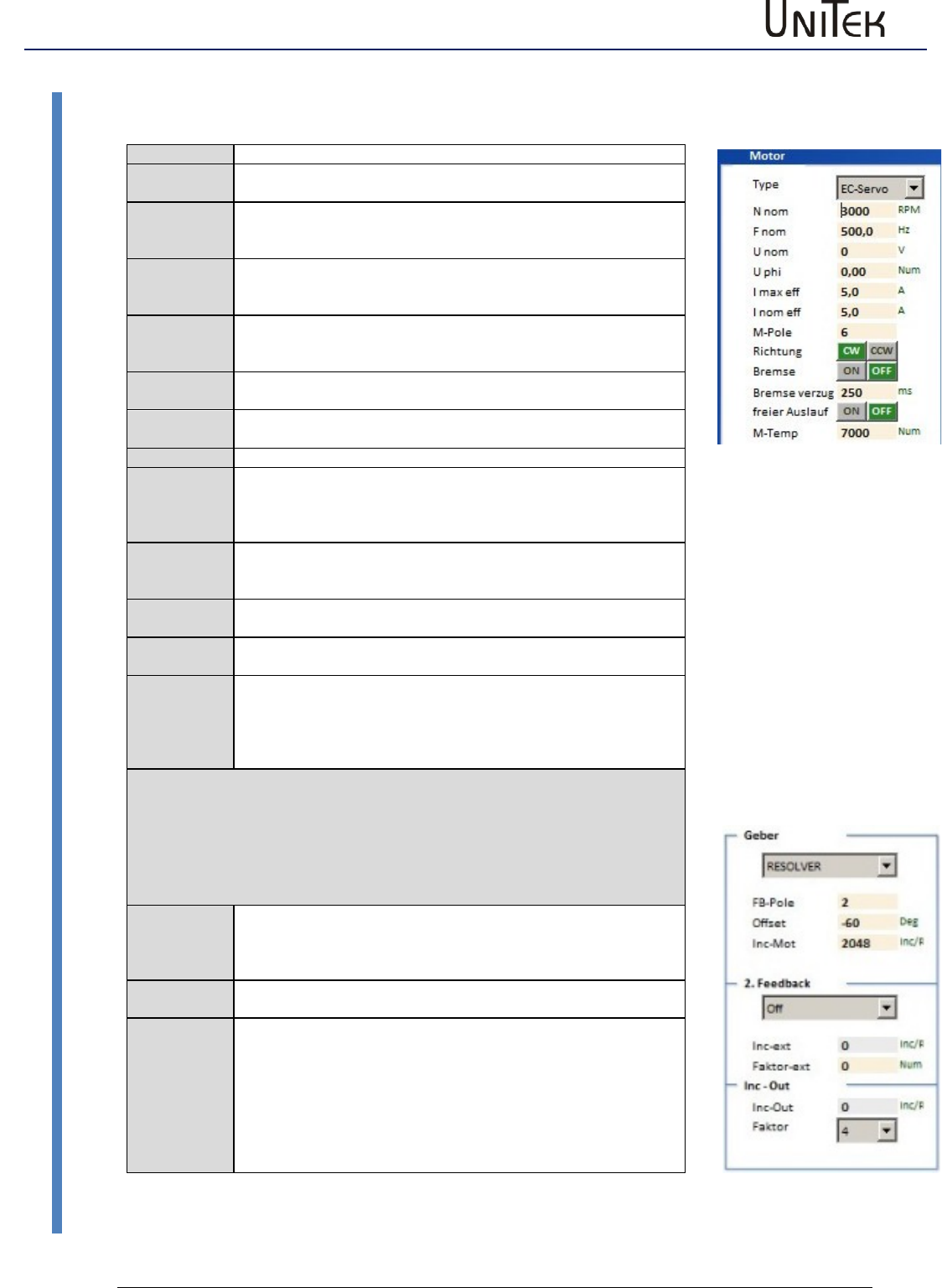
Motor setting
Setting window for the rated motor data
Check type plate, data sheet, and Unitek connection specifications!
Motor
Type
Motor type selection (EC-Servo, FU , FU-Servo, DC)
N nom
Motor speed (type plate)
Is used as calculation value for FU autotuning
F nom
Frequency at which the rated motor speed is reached.
Only for frequency converter mode.
(Type plate or motor data sheet)
U nom
Voltage for the rated motor speed
Only for frequency converter mode.
(Type plate or motor data sheet)
U phi
Motor power factor
Only for frequency converter mode.
(Type plate or motor data sheet)
I max eff
Max. permissible motor current
(Type plate or motor data sheet)
I nom eff
Permissible rated continuous motor current
(Type plate or motor data sheet)
M-Pole
No. of motor poles (2 x pole pairs)
Direction
Global change of the rotation direction.
The command value, the actual value, and the counting direction are
changed.
CW clockwise rotation, CCW counter-clockwise rotation
Brake
Motor selection with/without (ON/OFF) brake.
When it is set to ‘without’ (OFF) the switch-off delay (braking delay) is
out of function.
Brake delay
Attraction delay time of the electro-mechanical brake
Deceleration when no brake is connected
Free coasting
Free coasting (ON) or emergency stop braking (OFF) when the enable
(FRG/RUN) is switched off
M-Temp
Switching point for the motor over-temperature message.
Therewill be a warning message 6 (0x8fBit21) at 87 %
MOTORTEMP > 87 %
At 100 % (set value) the drive is switched off.
Error message 6 (0x8f Bit6) MOTORTEMP
Note:
The parameters lmax and lnom are also written into the parameter field ‘ current’.
The smaller value serves as limit.
Encoder
Encoder
Encoder system selection
(TTL incremental encoder, resolver, SIN/COS, DC tacho, etc.)
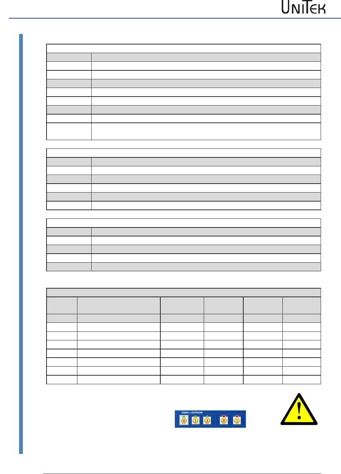
2nd Feedback
2nd feedback selection
INC-IN, INC-OUT , HAND , SSI
Inc-Out
Setting of the output incremental signals
Enable
Software – Manual N-Drive 3xx
Version 2017 / V1
30
Setting window for the feedback encoder
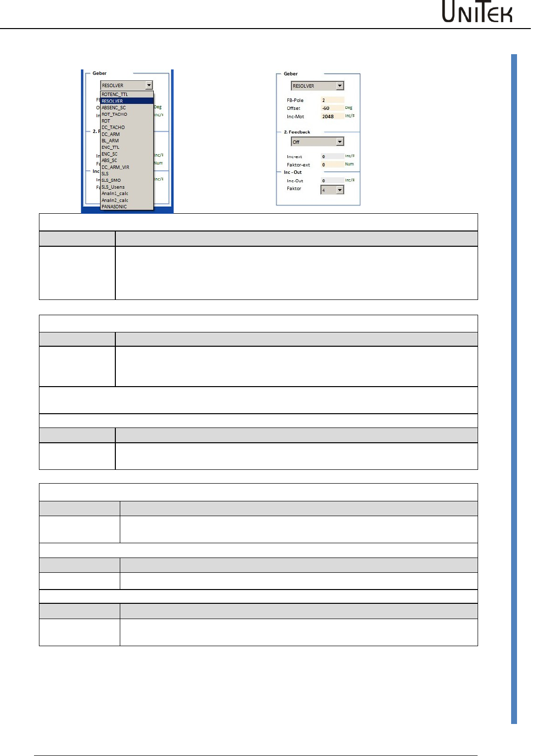
10.5 Setting window for the feedback encoder
RESOLVER- Encoder 10 kHz 2 Vpp
RESOLVER
F-Pole
Offset1
No. of encoder poles 2 to 12
Correction value for the mechanical encoder setting.
Polar wheel angle 0 to 360 degree
Automatic detection of the offset angle = see page AUTO
Incremental encoder 5 V TTL
ROTENC_TTL
Incremental encoder TTL with rotor position tracks
Offset
Inc. Mot
Correction value for the mechanical encoder setting
Automatic detection of the offset angle = see page AUTO
No. of pulses per revolution
Note: The no. of poles of the rotor position encoder must correspond to the no. of
motor poles!
ENC-TTL
Incremental encoder TTL without rotor position tracks
Inc. Mot
No. of pulses per revolution
Only for asynchronous motors or special drives
SINUS/COSINUS encoder 1 Vss
ABSENC_SC
1 Vss-Sin/Cos encoder with Sin/Cos-commutation tracks
Offset
Inc. Mot
Correction value for the mechanical encoder setting
No. of pulses per revolution
ENC_SC
1 Vss-Sin/Cos encoder without commutation track
Inc. Mot
No. of pulses per revolution
ABS_SC
Sinus-Cosinus signal per motor pole pair (analog Hall sensors)
M-Pole, FG-
Pole
No. of motor poles is equal to the no. of encoder poles
Enable
31
Version 2017 / V1
Software – Manual N-Drive 3xx
Setting window for the feedback encoder
10.6 Setting window for the feedback encoder
ROTOR POSITION ENCODER 5 V, 15 V
ROT_TACHO
Rotor position encoder with bl-tacho (DC tacho)
Offset
Correction value for the mechanical encoder setting.
ROT
Rotor position encoder without bl-tacho, only rotor signals
Offset
Correction value for the mechanical encoder setting.
BL-ARM
EC/AC motor without tacho
Note
The no. of poles of the rotor position encoder must correspond to the no. of
motor poles!
Feedback for DC motors
DC_TACHO
DC motor with tacho
Offset
120 = connection M1-M3 (0=M2-M3, -120=M1-M2)
DC-ARM
DC motor with armature voltage sensor (without tacho)
Offset
120 = M1-M3 (0=M2-M3, -120=M1-M2)
DC_ARM_VIR
Sensorless DC motor without tacho, without armature voltage measuring
Offset
120 = connection M1-M3 (0=M2-M3, -120=M1-M2)
Sensorless drives
SLS
Sensorless AC motor without feedback encoder
no setting
SLS_SMO
not yet available
SLS_Usens
not yet available
Parameter overview of encoder settings
Short
symbol
Function
Setting
range
Units
Notes
ID address
FB-Pole
No. of encoder poles
2..12
num
0xa7
Offset
Phase angle correction
0 .. +/- 360
degree
0x44
Inc-Mot
Encoder resolution
1024..8192
pulse/rev.
only binary
0xa6
Voltage
DC tacho voltage
mV/RPM
Inc-ext
Resolution of 2nd encoder
pulse/rev.
0xcfL
Factor
Multiplicator SIN/COS inc.
4..16
num
0x7e
In case of changing the feedback parameters it is necessary to reset
the parameter.
Write the parameter set into the EEPROM
(EEPROM<->RAM ) and re-read it.
read
write
Enable
Software – Manual N-Drive 3xx
Version 2017 / V1
32
Setting X8 as second counter input
10.7 Setting X8 as second counter input
Selection fot the 2nd counter input (2nd feedback)+
Off input switched off
INC-IN connected as input
INC-OUT connected as output
Hand Handwheel input
SSI SSI encoder input
INC-IN Setting X8 as input for incremental encoder signals
Incremental encoder TTL 5 V A,B,N +push-pull
Bridge between X8:1 and X8:6 (X8 switched as input)
Scale (Factor-ext.):
Calculate the transmission
1 motor revolution = 65536 num (internal counter)
Faktor-ext for the adaption of the 2nd encoder (0x7e)
Encoder_2_Scale = 65536 / encoder pulses per motor revolution *4 from
the 2nd encoder
Input at factor-ext. (0x7e) = Encoder_2_Scale * 16384
Example:
1 Motor revolution corresponds to 0.1 encoder revolutions
No. of encoder pulses 1000/rpm
Pulses per motor revolution 0,1*1000*4 = 400
Input at encoder_2_Scale
= 65536 / 400 = 163,840
Input factor-ext. (0x7e)
= 163,840 * 16384 = 2684354
Setting X8 as output for incremental encoder signals
The encoder signals from the motor (feedback) are output across the D-
connector X8 as TTL encoder signals for the CNC control.
Signals: channel A, channel /A, channel B, channel /B, Kanal N, channel /N
The encoder output is floating.
The voltage is supplied through the encoder cable of the CNC/PLC control.
Voltage supply +5 V ±0.2 V
The output signal corresponds to RS485.
Option: Internal supply from the servo
(LBR1+ LBR2)
Resolution:
For the –RS and –SC versions the resolution can be programmed.
For –IN the output corresponds to the no. of encoder pulses.
Factor Mulitplication factor for the basic no. of pulses for
SinCos (SC)
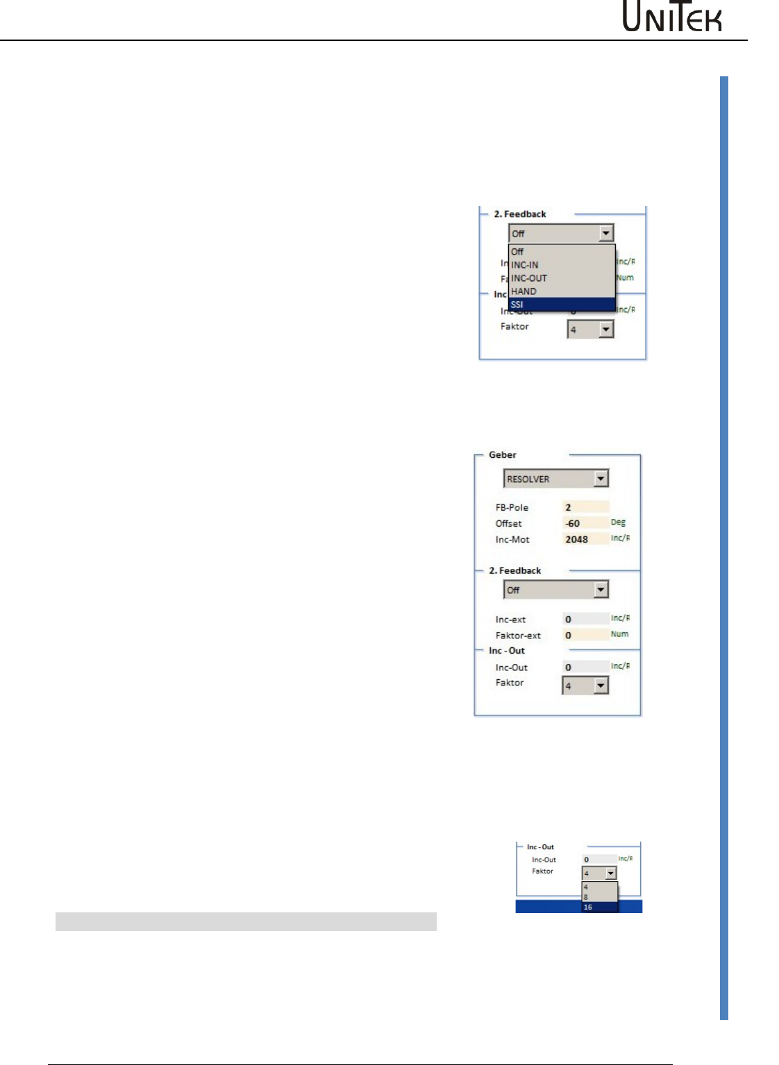
Inc-Out Setting value for the no. of pulses for resolver
Pulses per revolution
Resolution
Parameter
256
10 Bit
1024
12 Bit
4096
14 Bit
Enable
33
Version 2017 / V1
Software – Manual N-Drive 3xx
Brake setting
10.8 Brake setting
Brake setting
The max. braking power of the motor is applied when the
power has been switched off.
According to the electrical brake control the brake delay
(switching on/switching off) corresponds to the respective
type. (Brake delay)
A brake up to 24 V, 1 A can directly be switched by the
digital output.
For braking processes with higher current or voltage values
a relay must be inserted.
The brake output is activated on the page logic in the
parameter field output .
Click the command O-Break in the drop-down menu at
Dout 1, Dout 2 or Dout3 to transfer it to the display field.
Tranfer the operand = (equal) or ! = (not equal) in the drop-
down menu by clicking it.
The switching function of the output can be selected by
entering 0 or 1 into the parameter field (standard: 0)
Enter the switch-off delay of the motor brake in the
parameter field → brake delay (0 to 500 ms) of the input
field → motor.
When the brake is active, the state is displayed BRK1 in the
input field state.
Note: Connect a recovery diode or a varistor directly to
the brake connection at the motor.
Brake output on the logic side
Example
Digital outputs
Selection
Dout1
not used
Dout2
not used
Dout3
The brake is disconnected
from the power supply when
the enable is switched off.
Set the switch-off delay via
the brake delay.
Dout4
not used
Enable
Software – Manual N-Drive 3xx
Version 2017 / V1
34
Brake setting
Brake function
When the drive enable is switched off or the CAN command ENABLE OFF is received, the internal
speed command value N cmd Ramp will be ramped down to zero at a rate defined by Ramp-
Limit. After a fixed delay time of 50 ms, the Brake parameter will switch from 1 to 0. The braking
power rises. After the programmed time Brake delay has passed, the internal parameter GO is
switched to 0 and the servo is disabled (no torque applied).
Brake release function
If the brake is active and drive enable is switched on, the command value is maintained at 0 and
GO switches immediately to 1.
After 50 % of the delay time (brake-delay) has passed, the brake is switched off, and after the
complete delay time has passed, the command value will increase at a rate defined by Ramp-Acc.
Note:
The sum of the times R-Lim plus brake delay must be inferior to 1s.
When the enable is switched-off at 1.1s the hardware of the output stage is disabled.
The electric braking is interrupted and the drive decelerates freely. When the R-Lim plus brake
delay time is too long and has elapsed, the mechanical brake is triggered and stops the drive. der
zu langen Zeit von R-Lim plus Bremse verzug
Bremsen-
z. B. Sollwert
Anfahren
Hardware
GO (intern)
Ramp-Limit Ramp-Acc
50%50%
Fahrbefehl
Freigabe (RUN)
Ansteuerung
Bremsen-
Bremskraft
Bremsen Stillstand
100%
Brake-Delay Brake-Delay
Enable
35
Version 2017 / V1
Software – Manual N-Drive 3xx
Ballast circuit setting
10.9 Ballast circuit setting
For the units with a bus circuit setting (ZW monitor digital) DIG the ballast circuit is directly
controlled from the hardware.
With the bus circuit setting (ZW monitor analog) ANA the ballast circuit is controlled from the
TMS control board.
With an internal ballast resistance the setting parameters of the unit detection is automatically
adjusted.
With an external ballast resistance the values for the resistance (ballast R) and the resistance
power (ballast P) are entered as parameters.
Ballast INT = internal ballast resistor
EXT = external ballast resistor
Ballast-P Enter the resistor power in W
Ballast-R Enter the resistor power in Ohm
With an internal ballast resistance the ballast power is calculated from
the data of the device type.
With an external ballast reistance the ballast power is calculated from the entered values of
Ballast-P and Ballast-R.
The ballast power is displayed as Ballast-Leistung (0x45L) on the monitor side.
The dc bus voltage (DC-BUS dir), the ballast switching pulse (I-Regen, IBallast), and the ballast
power (Ballast counter) can be shown on the oscilloscope.
Selection by means of the drop-down menu.
There will be a warning at 87% of the ballast power (ballast circuit >87 % overloaded 0x8f Bit 31)
and at 100 % the device will be switched off and an error message is displayed (ballast circuit
overloaded 0x8f Bit15).
The function of the ballast circuit is displayed on the servo.
The command value directional bar of the 7-segment display (below left or right) is switched off
as long as the ballast circuit is active.
Enable
Software – Manual N-Drive 3xx
Version 2017 / V1
36
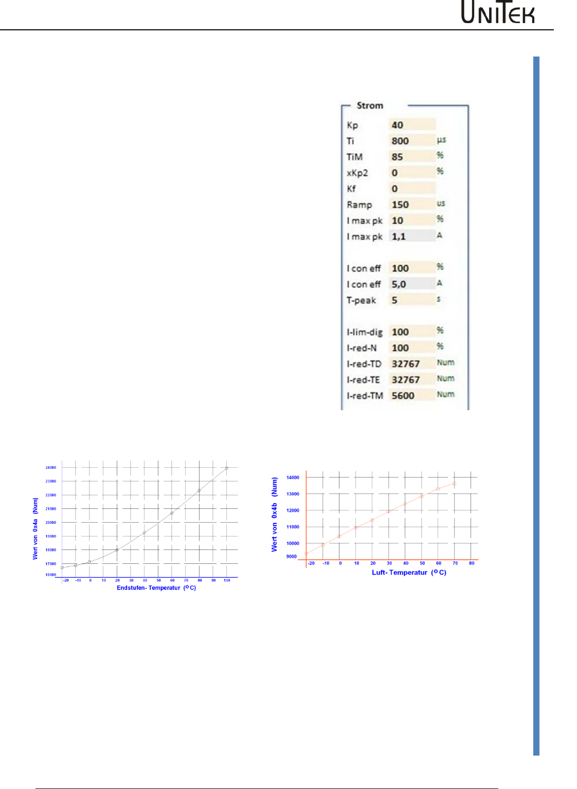
Motor temperature setting
10.10 Motor temperature setting
Motor temperature watchdog
Parameter motor temperature current reduction
I-red-TM 0xa2
Set I-red-TM only with linear temperature sensor!
Starting from the trigger point of the motor temperature
(I-red-TM 0xa2) the max. current limit is linearly reduced
to continuous current until the switch-off point (M-TEMP
0xa3).
Presetting 0xa2 = 5600
Warning I-MOTORTEMP when the set value is exceeded.
Parameter motor temperature fault switch-off
M-TEMP 0xa3
Presetting 0xa3 = 7000
Warning message at 87 % of the set M-Temp value.
Warning 6 MOTORTEMP >87 %
When the set value is exceeded, there will be the error
message 6 (MOTORTEMP)
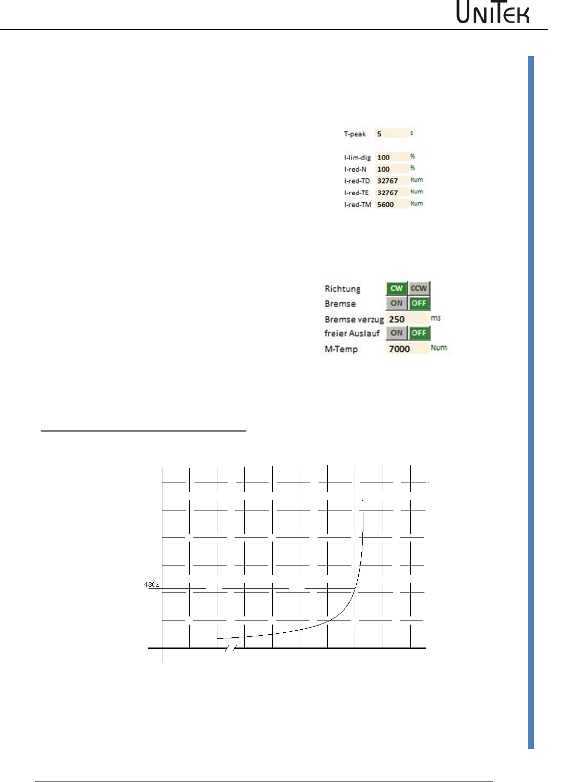
Setting with non-linear temperature sensor (PTC resistor)
only motor temperature fault switch-off M-TEMP 0xa3
Note: Temperature reduction is not possible
Example:
Error message and switch-off at 140 °C Setting M-Temp (0xa3) 4302 Num
For multiple, series connected sensors the set value is increased.
-20 20 80 100 120 130 140 150 160
0
2000
4000
6000
8000
10000
12000
Werte von 0xa3 (Num)
0
Motor- Temperatur ( C)
o
Enable
37
Version 2017 / V1
Software – Manual N-Drive 3xx
Motor temperature setting
Motor temperature watchdog
Parameter overview of the motor temperature
Short
symbol
Function
Setting
range
Units
Notes
ID address
I-red-TM
Triggering point
current reduction
Warning 0x8f-Bit 22
MOTORTEMP
Motor temperatuer >87 %
0..32000
num
Setting
parameter
0xa2
M-Temp
Switch-off point,
error message 0x8f-Bit6
MOTORTEMP
Motor temperature >100 %
0..32000
num
Setting
parameter
0xa3
T-motor
Current motor temperature
0..32000
num
Display
parameter
0x49
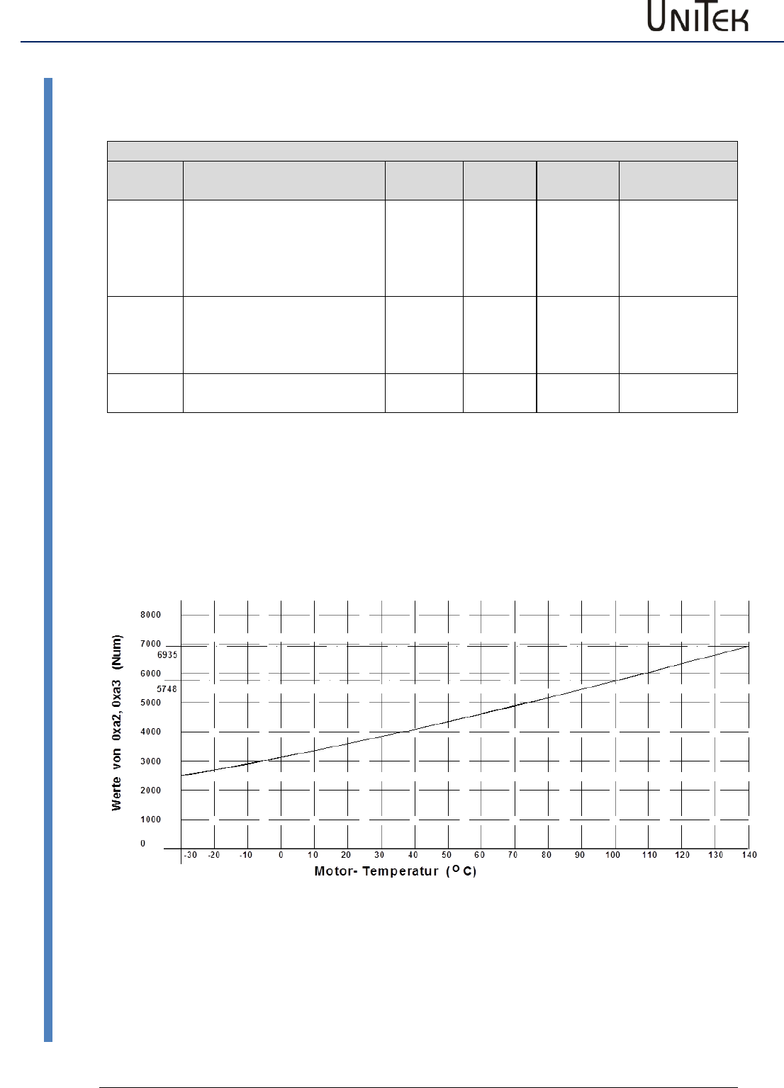
Motor temperature watchdog
Parameter motor temperatuer current reduction l-red-TM 0xa2
Parameter motor temperature fault switch-off M-TEMP 0xa3
Setting with linear sensor type KTY84
Example:
Warning and current reduction from 100 °C Setting l-Red-TM (0xa2) 5748num
Error message and switch-off at 140 °C Setting M-Temp (0xa3) 6935num
Enable
Software – Manual N-Drive 3xx
Version 2017 / V1
38
Motor temperature setting
Setting with linear sensor type PT100
Note:
Inaccurate temperature measuring due to a flat characteristic curve and internal
measuring tolerances.
An exact temperature measuring is only possible using a ballast measuring
amplifier.
Example:
Warning and current reduction from 100 °C Setting l-Red-TM (0xa2) 937num
Error message and switch-off at 140 °C Setting M-Temp (0xa3) 1036num
-30 -10 010 20 30 40 50 60 70 80 90 100
0
200
400
600
800
1000
1200
1400
1600
Werte von 0xa2, 0xa3 (Num)
Motor- Temperatur ( C)
o
110 120 130 14-20
1036
937
Enable
39
Version 2017 / V1
Software – Manual N-Drive 3xx
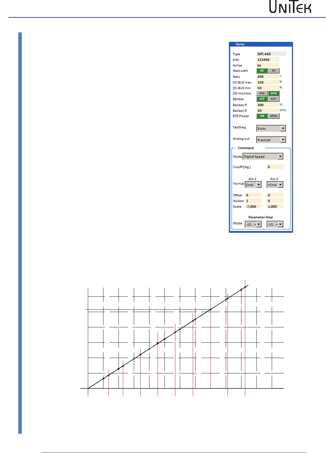
Setting of the power connection/bus circuit
10.11 Setting of the power connection/bus circuit
AC~, DC=
Selection ac or dc voltage
Mains power
supply
Rating of the voltage supply in V
Limit of the bus circuit voltage
(Take the setting values of the hardware manual
(bus circuit voltage 0xeb)
DC-BUS
max
Max. voltage limit (software).
200 % correspond to 32767 num = 2x rated voltage.
Setting value for the ballast circuit and over-voltage
watchdog.
Warning at 1.5 times rated voltage
OVERVOLTAGE 0x8f-24
Error message in case of over-voltage
OVERVOLTAGE 0x8f-8, the controller is disabled.
The hardware voltage watchdog works
independently from the software setting.
DC-BUS
min
Minimum voltage limit (software).
200% correspond to 32767 num
Below the min. voltage limit the controller is
disabled. In case of undervoltage the controller is
disabled and the error message ‘undervoltage’
(power voltage) 0x8f-Bit5 is displayed.
Setting values of the hardware manual
Example: MANUAL BAMOCAR
0 50 100 150 200 250 300 350 400 450 500
0
5000
10000
15000
20000
25000
30000
Wert von 0xeb [ Num ]
Zwischenkreis-Spannung [ V ]
100 200 300 400 500 700 800
BAMOCAR 400V
BAMOCAR 700V
Value of 0xeb [ Num ]
DC-Link voltage
900
0600
Enable
Software – Manual N-Drive 3xx
Version 2017 / V1
40
Output stage temperature
10.12 Output stage temperature
For units with an analog recording of the output stage
temperature the software watchdog can be programmed.
(Take the setting values of the hardware manual (bus circuit
voltage 0xeb).
l-red-TD
Setting value for the starting point of the
current limit reduction depending on the
output stage temperature.
l-red-TE
Max. temperature limit (software).
At 85% of the max. output stage
temperature a warning message
DEVICETEMP 0x8f-23 is displayed. When the
max. output stage temperature is reached,
the controller is disabled and the error
message overtemperature 0x8f-7 is
displayed.
The output stage temperature watchdog of
the hardware works independantly of the
software setting.
Setting values of the hardware manual
Example: MANUAL BAMOCAR
Temperatur-IGBT-Bamocar
Temperatur – Luft - Bamocar
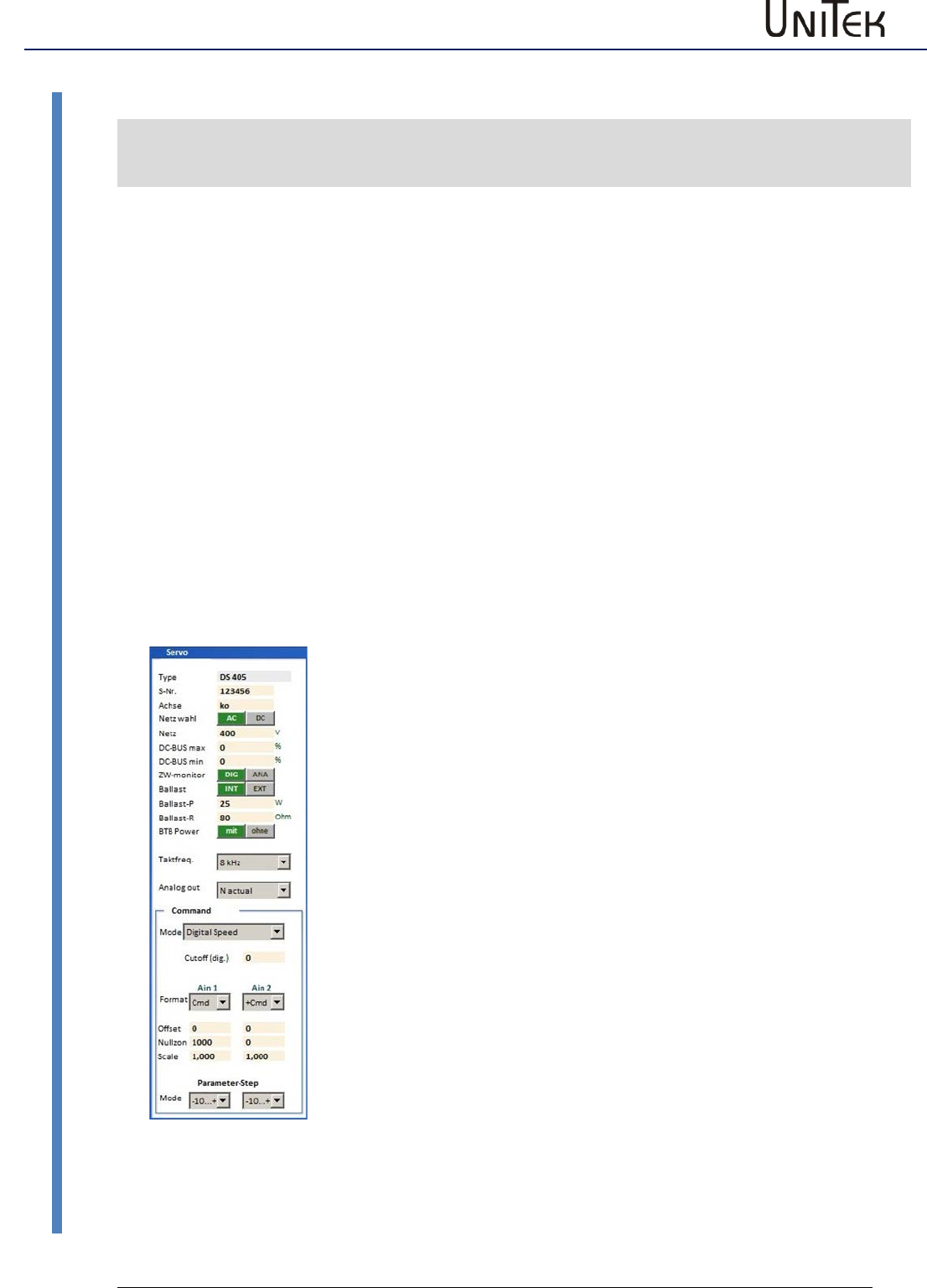
Enable
41
Version 2017 / V1
Software – Manual N-Drive 3xx
Setting field for rated servo data
10.13 Setting field for rated servo data
Servo setting parameters
Short
symbol
Function
Setting range
Units
Note
ID address
Type
Unit type
Type plate
Alpha-num
0x63
S-Nr.
Serial unit no.
Type plate
Alpha-num
0x62
Axis
Unit position identification
2 letters
Alpha-num
0xf8
Mains sel
Selection ac/dc voltage
Selection
0x5a-19
Mains
Power supply voltage
up to 480~,
up to 560=
V
0x64
DC BUS max
Max. bus circuit voltage
num
0xa5 H
DC BUS min
Min. bus circuit voltage
num
0xa5 L
ZW monitor
Selection bus circuit
analog-digital
0x5a-Bit 7
Ballast
Selection ballast resistance
internal external
0x5a-Bit 1
Ballast-P
Ballast resistance power
Type plate
W
0x65-L
Ballast-R
Resistance value
5 to 100
Ohm
0x65-H
BTB/RDY
Selection field BTB
with/without bus
circuit voltage
0x5a-Bit 6
Clock
frequency
Drop down menu
Selection
0x5y Bit 20-22
Analog out
Drop down menu
Selection
Selection
Command
Selection field command values
analog digital
0x36 Bit 12-13
Setting field for rated servo data
Type
The controller type is displayed (changes can only be made in the
factory)
S-Nr.
Serial no. is displayed (factory-set)
Achse
Axis specification 2 digits correspond to the circuit diagram of the
installation (entered by the user)
Main sel.
Power supply voltage AC~/DC= is displayed (factory-set)
Mains
AC and three-phase current voltage AC (30~ to 480 V~)
Battery voltage or dc mains (12 V= to 560 V=)
DC-Bus max.
Switching point bus circuit overvoltage
Error OVERVOLTAGE (overvoltage >1.8 UN) 0x8f Bit 8
DC-Bus min.
Switching point bus circuit under-voltage
Error POWERVOLTAGE (missing power voltage) 0x8f Bit5
ZW monitor
Selection bus circuit watchdog digital-analog (factory-set)
Ballast
Selection list ballast resistance (internal – external)
Ballast-P
Enter the power value for an external ballast resistor. Input in Watt.
In case of a ballast resistor overload a warning message is displayed.
Warning BALLAST (ballast circuit <87 %) 0x8f
Bit 31
Ballast-R
Enter the resistance value for an external ballast resistor. Input in
Ohm. Check the min. value.
BTB-Power
BTB-Message with or without bus circuit under-voltage.
Selection w-out (without) (BTB without under-voltage watchdog)
BTB without under-voltage watchdog.
When the enableand the power supply voltage are switched off the
RUN/BTB message remains active.
Selection with (with) (BTB with under-voltage watchdog)
BTB with under-voltage watchdog.
When the enableand the power supply voltage are switched off the
RUN/BTB is deactivated.
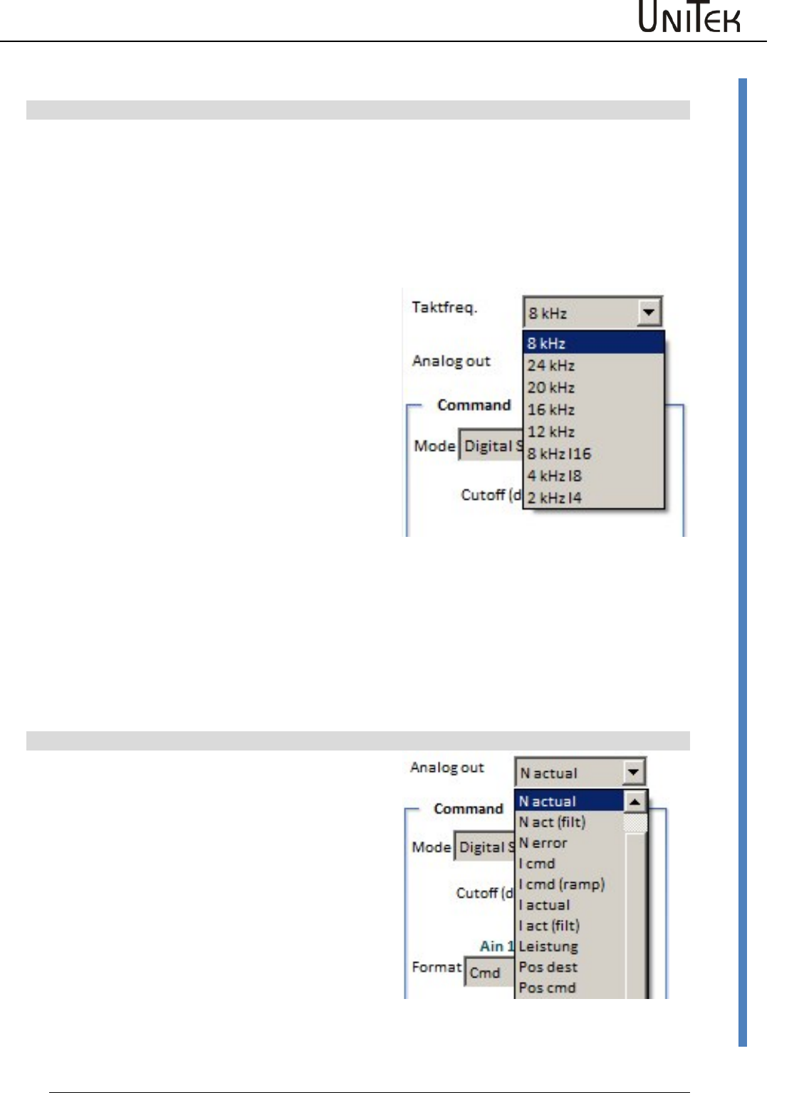
Enable
Software – Manual N-Drive 3xx
Version 2017 / V1
42
Setting field for rated servo data
10.14 Setting field for rated servo data
Clock frequenz
Selection of the switching frequency of the output
stage
Parameter 0x5a Bit 20-22
Presetting 8 kHz
Selection via the drop-down menu
Selection :
Pulse frequency with constant calculation speed
Values: 8, 12, 16, 20, 24 kHz
Current limits reduced at pulse frequency:
2 to 8kHz 100 %
12kHz 85 %
16kHz…….. 70 %
ab 20kHz 20 %
Selection:
Pulse frequency (kHz) with a higher calculation
speed (Ix).
Values: 2 kHz-l4, 4 kHz-l8, 8 kHz-l16
At the pulse frequencies 2 an 4kHz the continuous
performance increases.
Modification of the pulse frequency
Select frequency
Save the parameter set in the EEPROM on level 0
Read the parameter set from the EEPROM level 0
The changed frequency is transferred and the current
limits are reduced.
Analog out
Selection of analog outputs
Selection via the drop-down menu
Analog signals
The output voltage +/- 10 V
corresponds to +/- 100 % of the selected signal.
Digital signals
Selected digital signals provide 0 or +10 V.
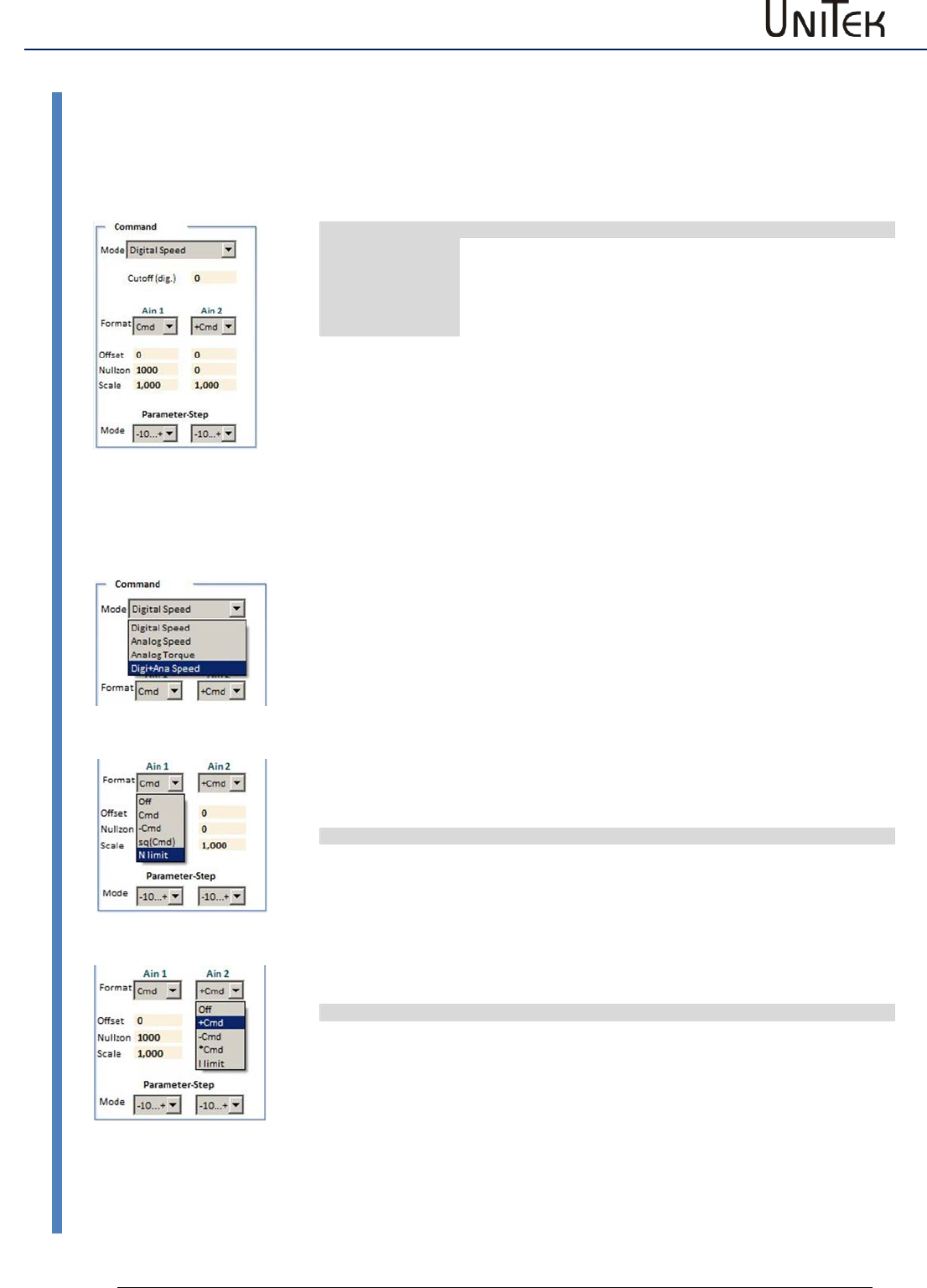
Enable
43
Version 2017 / V1
Software – Manual N-Drive 3xx
Command value setting
10.15 Command value setting
Analog inputs
Click the → button to open the drop-down menu.
Select the command value to be adjusted.
The selected function is highlighted in blue and it is transferred into the display by clicking it.
Cmd Mode
ID address
Digital Speed
Digital speed command value CAN-BUS, RS232, step
oscilloscope
0x36-12,13 =0
Analog Speed
Analog speed command value
0x36-12,13 =2
Analog Torque
Analog torque command value, voltage +/-10V
across the analog inputs AIN1 and AIN2
0x36-12,13=3
Digi+Ana Speed
Digital and analog command values are added
0x36-12,13=1
Analog Speed
Analog speed command value. Input via terminal strip X1.
Inputs Ain1 and Ain2
Max. input voltage ±11 V corresponds to ±32767 num
Analog Torque
Analog current command value. Input via terminal strip X1.
Inputs Ain1 and Ain2
Max. input voltage ±11 V corresponds to ±32767 num
This value corresponds to 200 % of the rated current
Reversal of the rotation direction for a unipolar command value with direction
signal
The unipolar command value is reversed by means of the direction command
(N cmd Reverse) via the programmed digital input. The input must be adjusted to
N cmd Reverse in the parameter field 'input/output.
Standstill with an analog command value for the speed and torque
Activate Speed Ramp 0 via a digital input or send it via the CAN BUS.
Format
The analog inputs Ain1 and Ain2 are assigned to a function via the format field.
Format Ain1
ID address
Off
switched off
0x36 Bit0-1 =0
Cmd
Speed command value
0x36 Bit0-1=1
-Cmd
reversed speed command value
0x36 Bit0-1=2
sq (Cmd)
quadratical speed command value
0x36 Bit0-1 = 3
N limit
Speed limiting 0-100%
for a digital speed and position control
(CmdMode = digital)
0.36 Bit15
Format Ain2
ID address
Off
switched off
0x36 Bit2-3=0
Cmd
Speed command value is added to Ain1
0x36 Bit2-3 =1
-Cmd
Speed command value is subtracted from Ain1
0x36 bit2-3=2
*Cmd
Speed command value is multiplied with Ain1
0x36 Bit2-3=3
l limit
external current limiting 0-200%
(for CmdMode = digital, analog speed or
analog torque)
0x36 Bit14
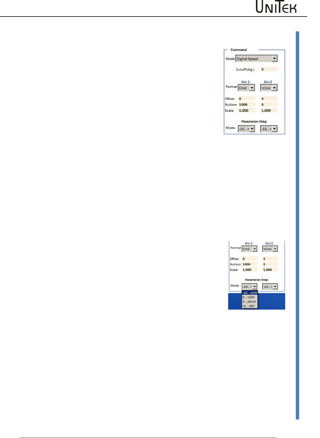
Enable
Software – Manual N-Drive 3xx
Version 2017 / V1
44
Command value setting
Offset
Compensation of the command value zero error the the input is analog.
With the command value OV alter the offset value such that the
parameter Ncmd Ramp is zero.
Zero zone
At an analog command value it is possible, by means of the parameter
zero zone, to set a range in which the speed is kept at standstill.
(Digital capture, 327 corresponds to 1 % of the speed)
Zero zone at speed command value
The command value is switched to zero within this zone. The drive is at a
standstill, no drift (no position parameter entered). For an external
torque which is larger than the servo current limit the drive can be
turned from the neutral position.
Zero zone at speed command value with position hold value
Within the zero zone the drive maintains its zero position by means of an
internal position-current-control.For an external torque which is larger
than the servo current limit the drive can be turned from the neutral
position.When the torque is smaller the drive returns to its zero position.
Note:
The parameters must be entered in the parameter field
'position-current'.
Note:
When an analog command value is provided from a PLC/CNC
position control, the value 0cut should be very low or zero.
Scale
Multiplication factor for the analog input signals.
Setting value +/- 0 to 7.500
Note: Resulting values superior to 11 V are trimmed. The result of the
command value scaling is displayed on the page ‘speed at’ Ain1, 2
scaled. (Ain1,2 scaled = Ain1,2 on +/- Offset x scale)
Mode
Input range for the analog command values
-10…+10 Bipolar command value +/-10 V
0….+10 V Unipolar command value
(directional sign on the page ‘Logik‘ via Ncmd Reverse)
4…20 mA Current command value (external resistance 500 Ohm)
+1…+9 Command value with potentiometer watchdog
External current limit
The analog input Ain2 is selected as external current limit via the format
adjustment I limit .
0 to +10 V correspond to 0-200 % of the current limit for the values
programmed in the parameter field 'current'.
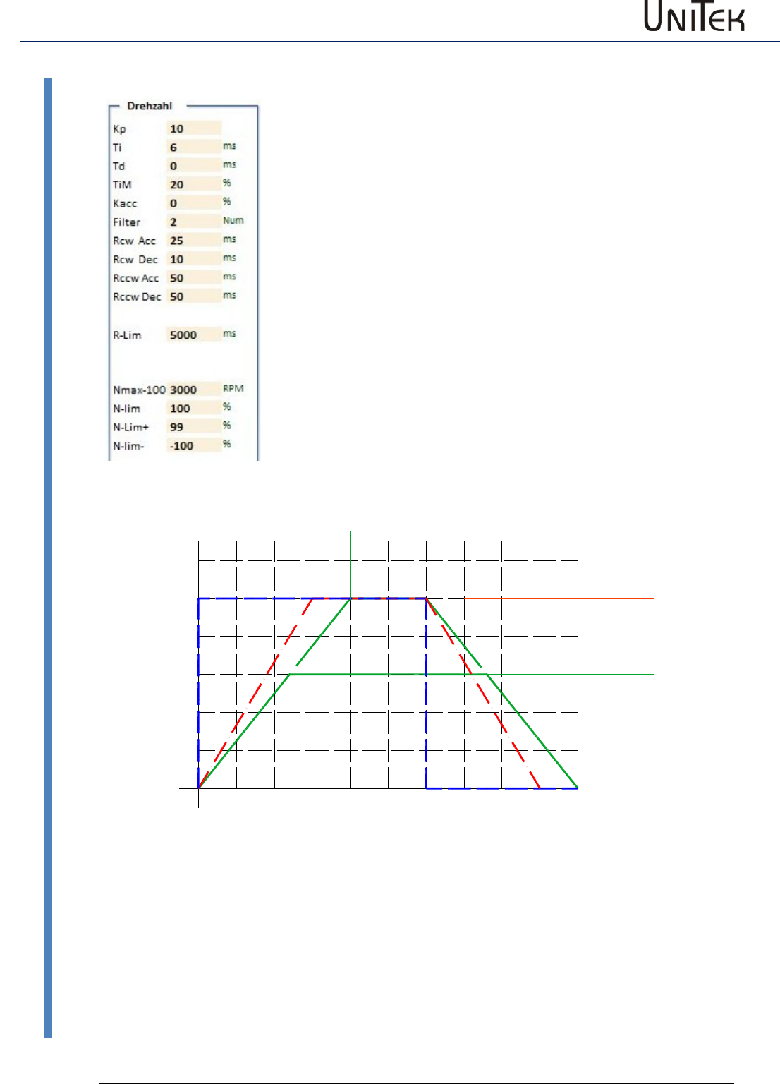
Enable
45
Version 2017 / V1
Software – Manual N-Drive 3xx
Command value setting
Linear ramp function
Rcw-Acc
Acceleration - positive rotation direction
Rcw-Dec
Deceleration - positive rotation direction
Rccw-Acc
Acceleration - negative rotation direction (1
Rccw-Dec
Deceleration - negative rotation direction (1
R-Lim
Emergency stop, output stage switch ramp
(1
=
Function not yet activated
Linear ramp
Time input for 100 % command value
Constant acceleration
Current peaks and acceleration and deceleration peaks are reduced.
0
40
80
100
200 400 600 800 1000
Zeitachse
Speed (%)
N-lim 60%
Nmax 100%
Acc-Ramp, Dec-Ramp 300
Acc-Ramp, Dec-Ramp 400
konstante Beschleunigung
Sollwert
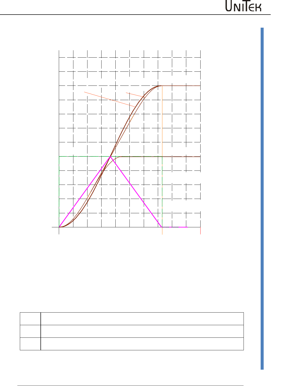
Enable
Software – Manual N-Drive 3xx
Version 2017 / V1
46
Command value setting
S-Ramp function / not yet active
S-Ramp function
The linear time function is altered to a S-shaped function (sine2).
The constant acceleration and deceleration is altered to continuous changing.
Jerk and current peaks are considerably reduced.
Command value limited for speed limiting
N-Lim
Speed limiting inferior to Nmax, (0 to 99 % of Nmax)
Setting of max. speed at position control.
N-lim+
Speed limiting inferior to Nmax for positive rotational direction (0 to 99 %=Nmax)
Activated via the logic input N clip(neg&pos)
N-lim-
Speed limiting inferior to Nmax for negative rotational direction (0 to -99 %=Nmax)
Activated via the logic input N clip(neg&pos)
Zeitachse
Speed (%)
Beschleunigung
S-Rampe
Beschleunigung
lineare Rampe
S-Faktor
groß
S-Faktor
klein
Speed limit 100%
Speed limit 50%
725ms
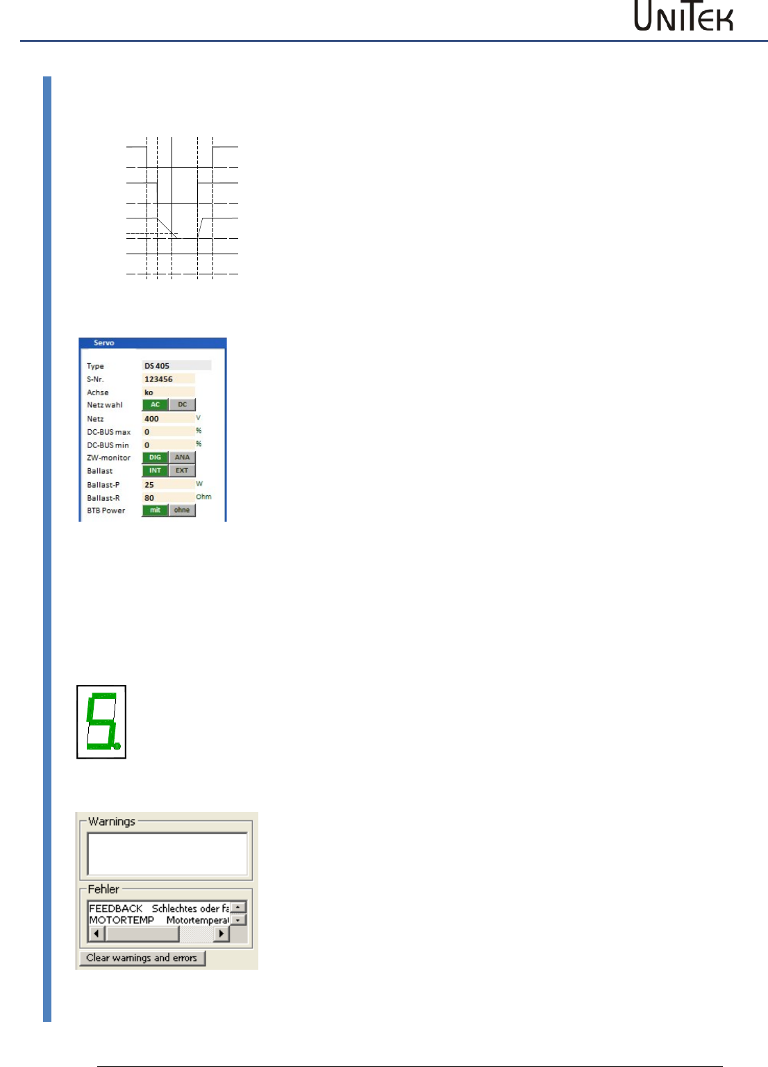
Enable
47
Version 2017 / V1
Software – Manual N-Drive 3xx
BTB / RDY setting
10.16 BTB / RDY setting
FAULT
BTB/RDY message (relay contact)
The BTB relay contact (solid state relay) is closed when the device is
ready (residual resistance 30Ohm). The BTB contact is opened when an
error occurs (resistance >1 MΩ).
The state BTB/Rdy (ready) is is displayed in the state field as Rdy.
The state 'not ready/BTB (error)' is indicated by the red LED 'fault' on
the front side.
BTB and the power supply voltage
When the power supply voltage is switched off the message state can be
selected via BTB power in the parameter field servo of the setting
window (under-voltage watchdog).
Selection BTB Power without
BTB without under-voltage watchdog.
When the enable and the power supply voltage are switched off, the
message RUN/BTB remains active.
Selection BTB Power with
BTB with under-voltage watchdog.
When the enable and the power supply voltage are switched off, the
message RUN/BTB is deactivated.
Error message and BTB/RDY
When a system-endangering error X (see list of errors) occurs, the BTB
signal is switched off. The drive will immediately be disabled internally.
(O_GO (OxE3) = 0)
On the Servo:
The red LED 'fault' (0x8f Bit 1) lights.
The error no. is indicated in the 7-segment display.
On the pc:
The error states are displayed in the field 'fault'.
The error messages are reset:
- when the drive enable (RUN) is switched on
- when the auxiliary voltage (+24 V) is switched on
- when the parameter 'cancel error' is sent (can also be
programmed as digital input by page Logic)
RUN/FRG
POWER/Netz
RDY/BTB
DC-BUS/
Zwischenkreis
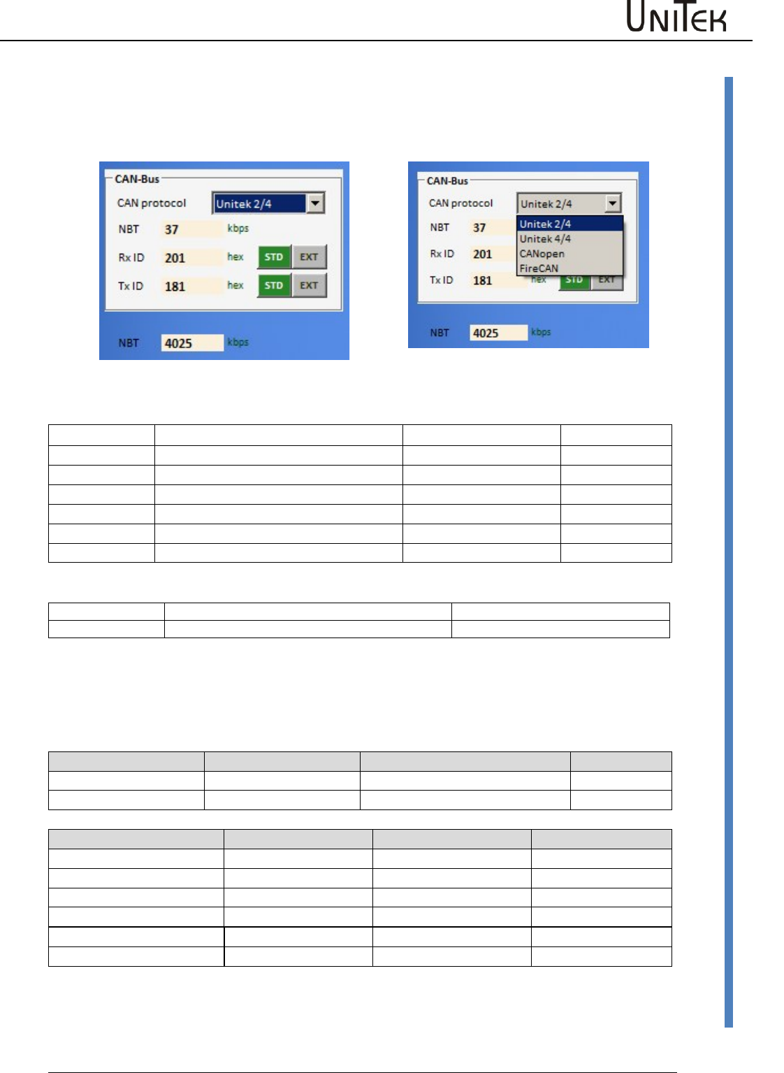
CAN-BUS settings
Software – Manual N-Drive 3xx
Version 2017 / V1
48
Settings CAN-BUS
11 CAN-BUS settings
11.1 Settings CAN-BUS
Input fields:
Information
Rx ID
Receive ID
-Brp
Tx ID
Send ID
-Sjw
BTR
Bit rate
-Tseg1
(Hexwert)
-Tseg2
-Sam
NBT Bit rate
(kBaud)
Selection switch
Position
0-14
15
Function
Supplementary value for the basis ID
see chapter ‘firmware download‘
The addresses for receive/send ID and the bit rate are set in the CAN bus parameter field of the
setting window. Switch the auxiliary voltage off and on after changes have been made in the CAN
programming!
Address
Short symbol
Presetting (default)
ID address
Receive address
Rx ID (COB-ID RPDO1)
0x201
0x68
Send address
Tx ID (COB-ID TRDO1)
0x181
0x69
Bit rate NBT
BTR setting value
Max. cable length
0x73
1000 kBaud
in prep.
20 m
500 kBaud
0x4025
70 m
Presetting
625 kBaud
0x4014
70m
LABOD-CNC
250 kBaud
0x405C
100m
125 kBaud
0x4325
100 m
100 kBaud
0x4425
100 m
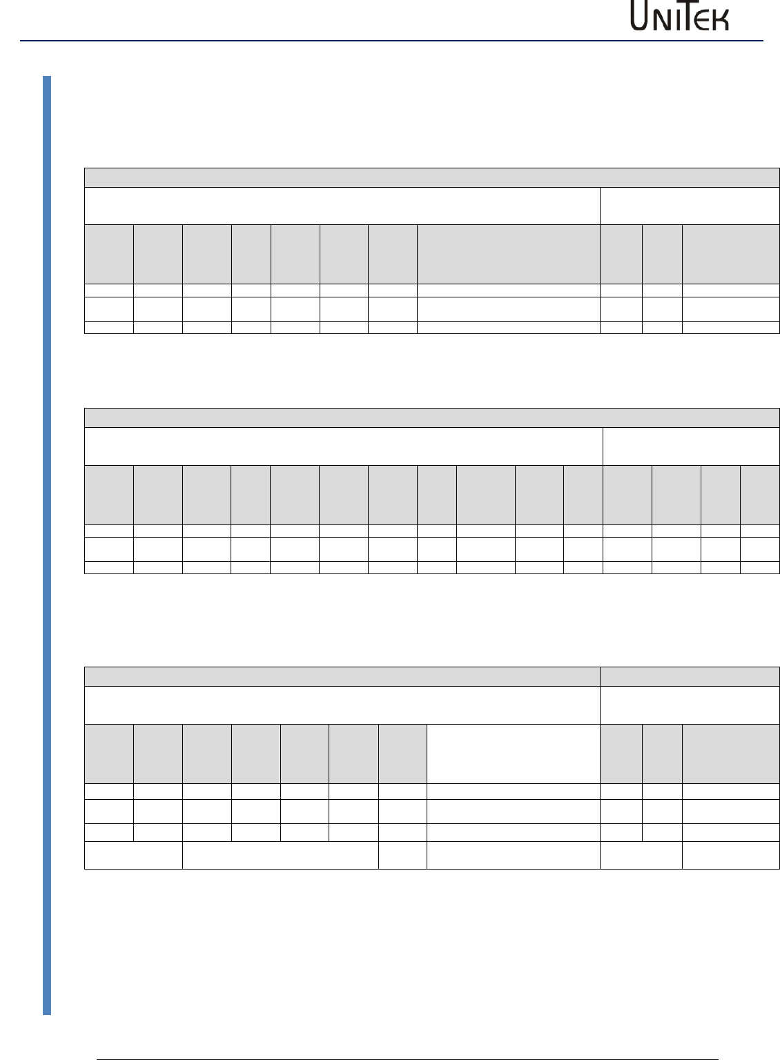
CAN-BUS settings
49
Version 2017 / V1
Software – Manual N-Drive 3xx
Aufbau serielles Protokoll
11.2 Aufbau serielles Protokoll
RS 232 16 bit
Sending from the pc to the drive
Response from the drive
to the pc
Char1
Char2
Char3
Char4
Char5
Char6
Char7
Byte 1
Byte 2
RegID
RegID
Data
Data
Data
Data
Sync
Data
Data
Bits
07..04
Bit s
03..00
Bits
15..12
Bits
11..08
Bits
07..04
Bits
03..00
"X"
Bits
07..04
Bits
07..04
ascii
ascii
ascii
ascii
ascii
ascii
ascii
binary
binary
RS 232 32 bit
Sending from the pc to the drive
Response from the drive
to the pc
Char1
Char2
Char3
Char4
Char5
Char6
Char7
Char8
Char9
Char10
Char11
Byte1
Byte2
Byte 3
Byte4
RegID
RegID
Data
Data
Data
Data
Data
Data
Data
Data
Sync.
Data
Data
Data
Data
Bits
07..04
Bits
03..00
Bits
31..28
Bits
27..24
Bits
23..20
Bits
19..16
Bits
15..12
Bits
12..08
Bits
07..04
Bits
03..00
„X“
Bits
07..04
Bits
07..04
bits
07..04
Bits
07..04
ascii
ascii
ascii
ascii
ascii
ascii
ascii
ascii
ascii
ascii
ascii
binary
binary
binary
binary
Example: Speed actual (actual speed value) 16 bit
+/-32767 corresponds to +/-100 %
Sending from the pc to the drive
Response from the drive
to the pc
Char1
Char2
Char3
Char4
Char5
Char6
Char7
Byte 1
Byte 2
Reg
ID
Reg
ID
Data
Data
Data
Data
Sync
Data
Data
Bits
07..04
Bit s
03..00
Bits
15..12
Bits
11..08
Bits
07..04
Bits
03..00
"X"
Bits
07..04
Bits
07..04
3
D
0
0
3
0
X
lo
hi
regID read
read (0x3D)
speed actual
actual speed value (0x30)
ascii
value of 0x30

CAN-BUS settings
Software – Manual N-Drive 3xx
Version 2017 / V1
50
Interface RS232
11.3 Interface RS232
Changing the baud rate in the drive
Selection 9600 or 115200
Default 115200
Setting with 0x5a Bit 15 (0x8000)
Bit 15 0 corresponds to 115200
Bit 15 1 corresponds to 9600
The baud rate saved in the device is display when switching on the auxiliary voltage 824V=), (after
the firmware version is displayed).
Bd0 corresponds to 115200
Bd1 corresponds to 9600
First, the firmware version is displayed (e.g. 2 3 2),
then the baud rate (e.g. b d 0)
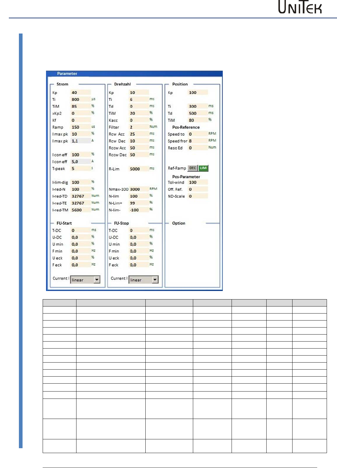
Parameter
51
Version 2017 / V1
Software – Manual N-Drive 3xx
Current controller parameters
12 Parameter
12.1 Current controller parameters
Parameter
Function
Setting range
Presetting
Units
Step
ID address
Kp
Proportional amplification
0 to 100
10
Num
1=0.1
0x1c
Ti
Integration time
150 to 10000
600
ms
150
0x1d
TiM
max. integrat. time memory
0 to 100
50
%
1
0x2b
xKP2
TiM discharge amplification
0 to 100
0
%
1
0xc9
Kf
Current pilot control
0 to 30
0
Num
1
0xcb
Ramp
I command value ramp
0 to 10000
600
ms
150
0x25
I max
Current limit, peak current
up to 2x I device
2xIdevice
Apeak
0,1
0xc4
I max
Current limit, peak current
up to 2x I device
2xIdevice
Apeak
0,1
0xc4
I con
Current limit, cont. current
0 to I device
Idevice
Aeff
0,1
0xc5
I con
Current limit, cont. current
0 to I device
Idevice
Aeff
0,1
0xc5
T peak
Over-current time
0 to 30
5
s
1
0xf0
I limit (dig)
Current threshold value
0 to 100 lmax
100
%
1
0x46
I-red-N
Current reduction by speed
0 to 100
100
%
1
0x3c
I-red-TD
Start of current reduction
by power stage
temperature
0 to 32767
21000
num
1
0x58
I-red-TE
Stop of current reducation
by power stage
temperature
0 bis 32767
23000
num
1
0x4c
l-red-TM
Current reduction by motor
temperature
0 bis 32767
5600
num
1
0xa2
Setting window for the
controlling parameters.
For further settings refer
to the pages 'speed' and
'oscilloscope'.
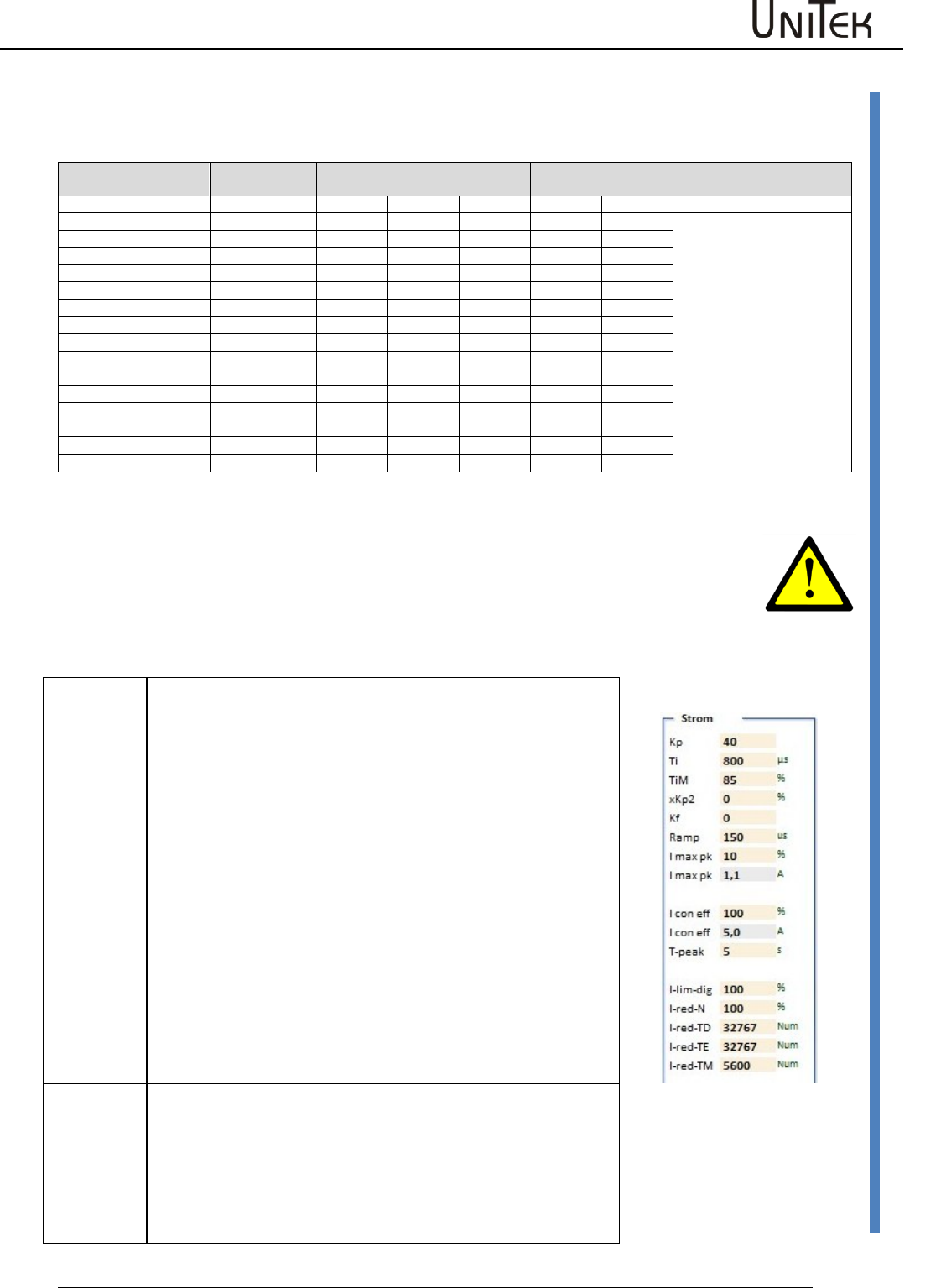
Parameter
Software – Manual N-Drive 3xx
Version 2017 / V1
52
Current controller parameters
Conversion of the current parameter values
For the digital communication via RS232 or CAN-BUS the numerical values for the rated value
have to be observed. The numerical values are displayed in the track field.
Actual current range
I 100% (0xee)
Calibration rated current I-device
Peak current
DC disabled
Note
Max. value +/- 9Bit
mV
num
Aeff
Apeak=
Num
Apeak=
DS 205/403/405
550
440
5
7
640
10
Limiting in the parameter
field 'motor' and 'current'.
The lower value is effective.
DS412
800
640
12
17
920
24
DS420
700
560
20
28
800
40
DS 450
416
328
50
70
480
100
DPC 450
416
328
50
70
480
100
DPC 460
DS 475 / BAMO-D3
416
328
75
105
480
150
BAMOBIL-D3- 50/ 250
870
700
25/125
35/175
1020
50/250
BAMOBIL-D3- 80
560
450
40
56
650
80
BAMOBIL-D3- 100
700
560
50
60
800
100
BAMOBIL-D3- 120
840
670
60
84
970
120
BAMOBIL-D3- 350
610
490
175
245
710
350
BAMOBIL-D3- 450
785
630
225
315
910
450
BAMOCAR-D3-250
625
700
125
176
1020
250
BAMOCAR-D3-400
500
560
200
282
810
400
Current controller setting window
The current controller parameters are determined by the motor data such as winding inductance
and winding resistance.
Note:
The current controller parameters may only be modified by trained and skilled personal.
Check all setting effects by means of the NDrive oscilloscope.
Improperly set amplification parameters may damage the controller or the drive.
Control parameters
Kp
Input for the proportional amplification in the current
controller.
Setting range 0 to 100 (nominal 10 to 40)
Presetting 10
Formula:
Kp too low:
compensation error, bad dynamics, low-frequ. vibrations
Kp too high:
strong motor noise, high-frequency vibrations
Note: overshoots on the current actual value. Optimize the
amplification to min. overshoots.
Ti
Input for the integration time in the current controller.
Integral – time constant
Setting range 150 to 10000 (nominal 600 to 2000)
Presetting 800
Ti too high: low-frequency vibrations
Ti too low: high-frequency vibrations, strong vibration
tendency
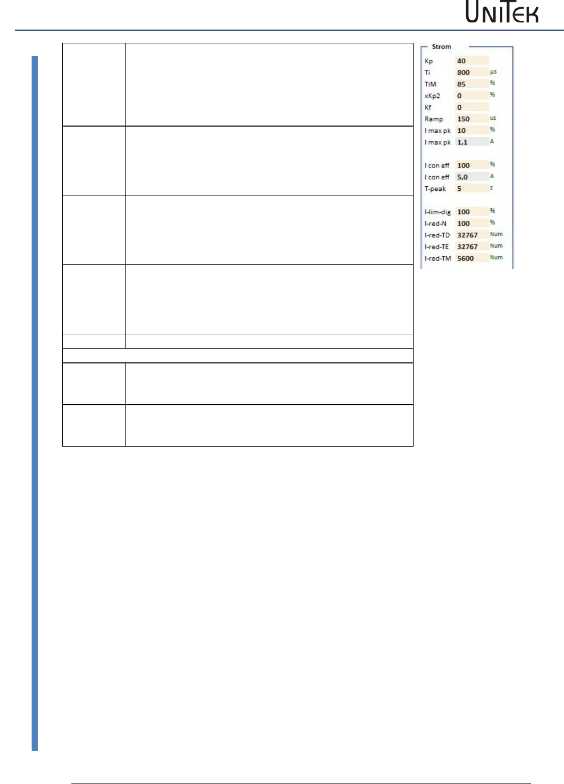
Parameter
53
Version 2017 / V1
Software – Manual N-Drive 3xx
Current controller parameters
TiM
Max. value from the integral memory
Setting range 0 to 100% (nominal 70 to 100 %)
Presetting 85 %
If adjusted too low, the speed (output voltage) is not
reached.
xKp2
Amplification factor for the attenuation of the current actual
value overshoots.
Setting range 0 to 100 % (nominal 10 bis 50 %)
Presetting 0%
If adjusted too high, there is a risk of current oscillations.
Kf
Pilot control for the compensation of the operating delay in
the controller.
Setting range 0 to 100 % (nominal 10 bis 50 %)
Presetting 0%
If adjusted too high, there is a risk of current oscillations.
Ramp
Current increase limiting
The current increase to 100 % type current iss et in µs.
Setting range 0 to 100 % (nominal 10 bis 50 %)
Presetting 0%
If adjusted too high, there is a risk of current oscillations.
Current limits
l max pk
Input for the peak current from 0 to 100 %
100 % = 2*l device in A pk
Display in A pk in the field I max pk (A eff = 0.707x Apk)
I con eff
Input for the continuous current from 0 – 100 %
device ratet currnt (l device)
Display in A eff in the field I con eff below
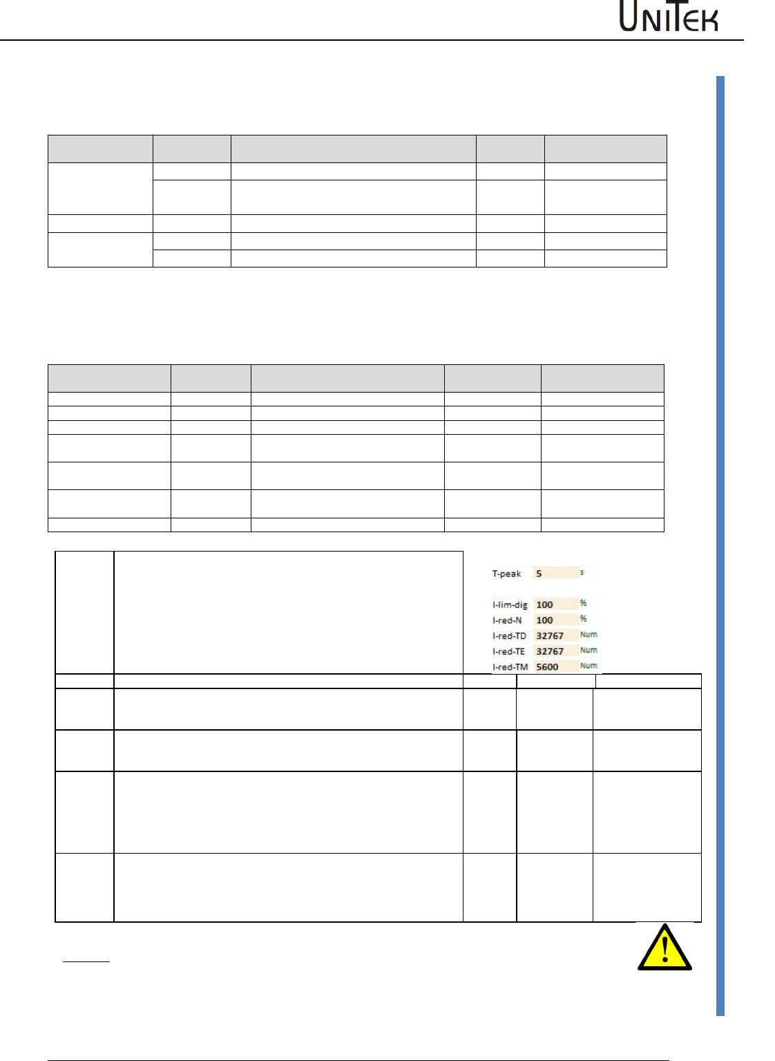
Parameter
Software – Manual N-Drive 3xx
Version 2017 / V1
54
Current reduction parameters
12.2 Current reduction parameters
Static current reduction
Current reduction
by means of
Symbol
Function
Parameter
Range
Motor
I max eff
Peak current limiting for the motor
0x4d
0 to xxA
I nom eff
Continuous current limiting for the
motor (type plate)
0x4e
0 to xxA
Servo
l max pk
Peak current limiting for the servo
0xc4
0 to 100 % of Imax
l nom eff
Continuous current limiting for the servo
0xc5
0 to 100 % of Icon
The respectively lower value of the peak current values and continuous current values are
effective. They are displayed as current Imax (in A) in the parameter field 'servo' and as icon.
Dynamic current reduction
Current reduction by
means of
Short symbol
Function
Parameter
Range (with 0 = off)
Time
T peak
Over-current time function
0xf0
0 to 300 s
Input (command)
I lim-dig
Reduction via digital input (CAN)
0x46
0 to 100 % Imax
Speed
I red-N
Over-current speed function
0x3c
0 to 32767 Num
Power stage temp.
I-red-TD
Start of reduction via power stage/IGBT
temperature
0x58
15000 to 24000 Num
Power stage temp.
I-red-TE
End current reduction by power stage
/IBGT temperature
0x4c
0 to 32763 Num
Power stage shut off
Emergency stop via the power stage
temperature
(Fix)
25200 Num (83 °C)
Motor temperature
I-red-TM
Reduction via the motor temperature
0xa2 0xa3
0 to 32767
T peak
At a current superior to the adjusted continuous current (Icon) a time
function is started. When the time function is elapsed the current limit is
reduced to the continuous current value.
Warning message in the state Iuse-rchd
The time is set by means of the parameter T peak (0xf0). If the current is
lower than the continuous current (Icon) the time memory is removed.
The reset time is 2 x T peak.
If the output stage temperature reduction has been selected by means of
the parameters I-redTD and I-red-TE the time function is switched off.
State
Warning
Error
I lim-dig
On the logic page a digital input can be programmed at I limit (dig) .
If this input is activated or if a CAN command is received for this input, the
current limiting is reduced to the parameter value I lim-dig (0x46) .
Ird-Dig
I-red-N
The current limit is linearly reduced from the speed value set in the
parameter I-red-N (0x3c).
At rated speed the current limit corresponds to the continuous current.
Ird-N
I-red-TD
l-red-TE
There is a state message when the output stage temperature set in the
parameter I-red-TD (0x58) is exceeded.
If the temperature still increses, the current limit is reduced.
When the parameter value I-red-TE (0x4c) is reached, there will be an
emergency switch-off. If I-red-TD (0x58) is set to 0 or if the value of I-red-
TE (0x4c) is smaller than I-red-TD (0x58), the function is switched off.
Ird-TI
DEVICETEMP
> 87 %
0x8f BIT23
DEVICETEMP
0x8f Bit7
I-red-TM
There is a state message when the motor temperature set in the
parameter I-red-TM (0xa2) is exceeded.
If the temperature still increses, the current limit is reduced. When the
parameter value M-Temp (0xa3) is reached, there will be an emergeny
switch-off.
IRD-TM
MOTORTEMP
> 87 %
0x8f BIT22
MOTORTEMP
0x8f Bit6
Attention:
The warning messages displayed in the field 'state' must be observed!
If the current limits are reduced, this might cause failures of the machine or the
installation.
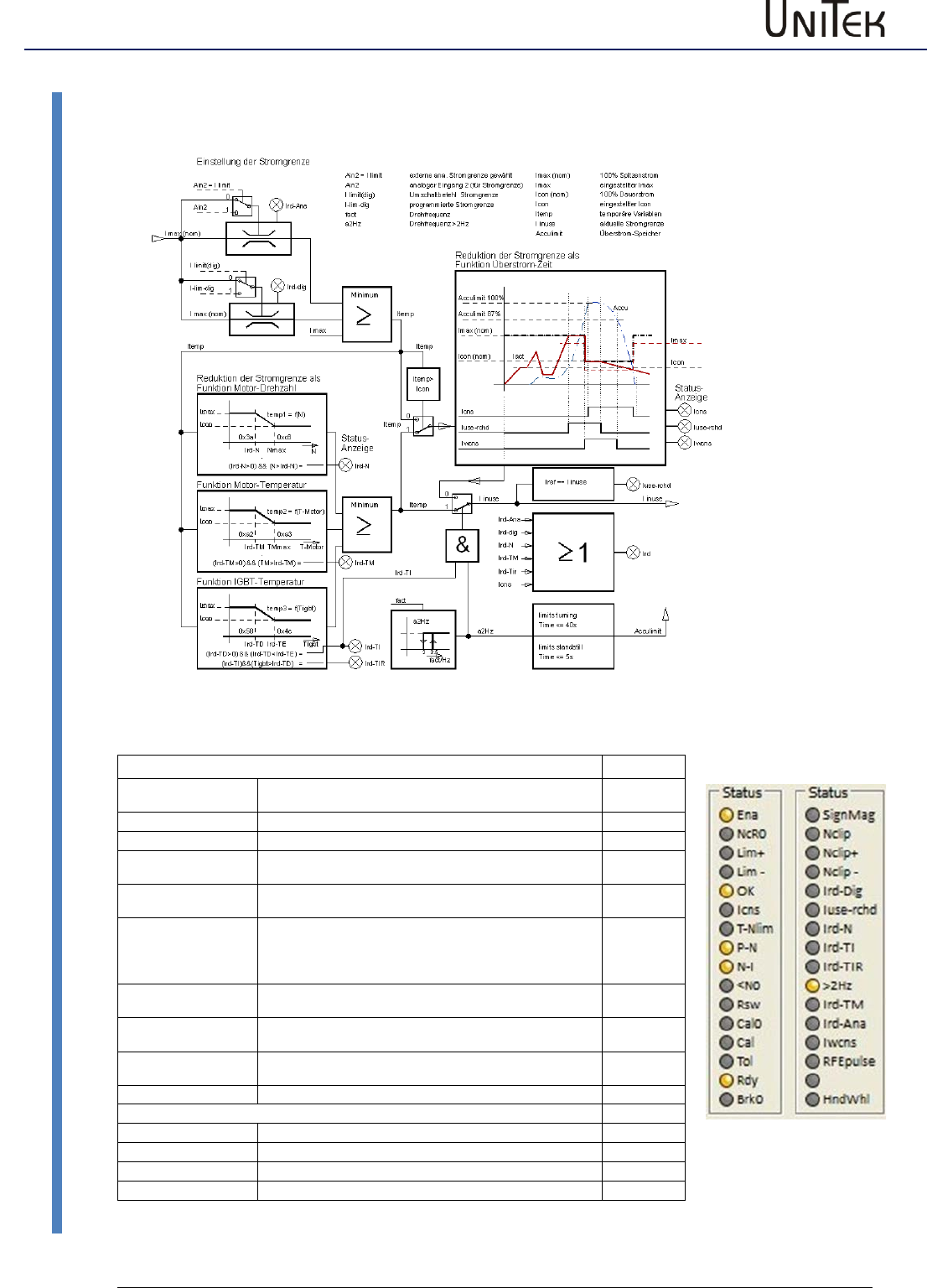
Parameter
55
Version 2017 / V1
Software – Manual N-Drive 3xx
Current reduction functions
12.3 Current reduction functions
States
address
Ird-dig
Current limit reduced to the value programmed as Ilim(dig).
Activated with 0xa5 Bit
0x40 Bit 20
Iuse-rchd
Actual current value at the current limit
0x40 Bit 21
Ird-N
The current limit is reduced when the speed is rising
0x40 Bit 22
Ird-TIR
The current limit is reduced when the output stage
temperature is rising
0x40 Bit24
Ird-TI
The current limit is reduced to continuous current via the
output stage temperature
0x40 Bit23
<10Hz
If the roatation frequency is smaler 10Hz (blocking
protection) (0x5a, bit31=0) current limit will be reduced,
(0x5y, bit 31=0) switching frequence will be set to 4 kHz.
0x40 Bit25
Ird-TM
The current limit is reduced when the motor temperature is
rising
0x40 Bit26
Ird-Ana
The current limit is reduced via the analog input 2,
0 to 10V = 0 to 100% peak current
0x40 Bit 27
Iwcns
Warning - current limit accumulator (accumulator limit)
charged to 87.5%.
0x40 Bit28
Icns
The current limit is reduced to continuous current
0x40 Bit5
Measured values (monitor)
Tmotor
Active motor temperature
0x49
Tigbt
Active output stage temperature
0x4a
Tair
Active air temperature in the servo
0x4b
Irda
Active current limit
0x48
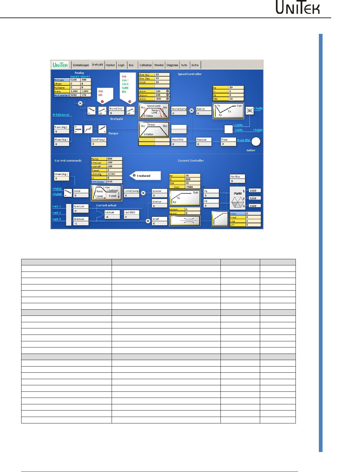
Parameter
Software – Manual N-Drive 3xx
Version 2017 / V1
56
Current controller parameters
12.4 Current controller parameters
Speed window (current)
Current controller
Block diagram with input fields for the control parameters and display fields for numeric values.
Command values (current)
The current command valueis provided by:
ID address
I Spd
Speed controller output
I Tor
Torque command value after ramp
I Pos
Position controller output (Pos -> current)
I man
Fixed input
input
0x21
I cmd
Current command value
display
0x26
I cmd-Ramp
Current command value after ramp and limiting
display
0x22
Actual values (current)
Iq actual
Active current
display
0x27
Id actual
Reactive current
display
0x28
I act
Summary current
display
0x20
I act monitor
Summary current after display filter
display
0x5f
Stromregel-Werte
Iq error
display
0x38
Id error
display
0x39
Id ref
display
0x23
Vq
display
0x29
Vd
display
0x2a
DC-BUS
Bus voltage
display
0xeb
V out
Output voltage
display
0x8a
V red
0x8b
V kp
0xac
V Ti
0x8d
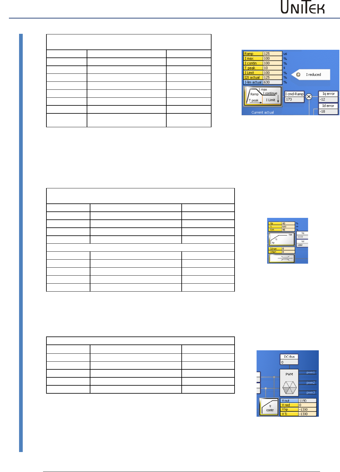
Parameter
57
Version 2017 / V1
Software – Manual N-Drive 3xx
Current controller parameters
Setting field Ramp Parameters are also on the page
‘settings‘
Parameter
Function
Address
Ramp
I-command value ramp
0x25
I max pk
Peak current Apeak
0xc4
I con eff
Continuous current
0xc5
Tpeak
Time peak current
0xf0
I-lim-dig
Current reduction with input
0x46
I t
Load
0x61
I lim inuse
Display current reduction
0x48
The current command value (I cmd) is processed in the setting field (ramp). The current increase (ramp), the peak
current (Imax), the continuous current (Icontin), and the peak current time (T peak) are set.
The summarized current reductions through speed, current, and temperature are displayed at I limit and I lim
actual.
At reeduced current the LED Ireduced lights. The result of the current command value processing is shown in the
display field ‘current command value after ramp’ (I cmd-Ramp).
Setting field - Current controller Parameters are also on the page
‘settings‘
Parameter
Function
Address
Kp
Proportional amplification
0x1c
Ti
Integration time
0x1d
TiM
Max. integration time memory
0x2b
???
???
0xcc
Setting field - Field control
Id nom
0xb2
Id min
0xb5
V red
Field weakening from % Vout
0x8b
V kp
Amplification field weakening
0x8c
V Ti
Integration time field weakening
0x8d
The current actual values (I-Ist1, I-Ist2, I-Ist3) are evaluated as Iq-actual and Id-actual. The displayed current actual
value (I act monitor) is obtained from the current actual value (I actual) by means of a filter.
The Iq and Id errors are processed in the current controller by means of the amplification parameters (Kp, Ti, TiM).
The reference value for the Id control is generated via the vector control feedback.
PWM Display Parameters are also on the page ‘settings‘
Parameter
Function
Address
Vdc-Bus
0xeb
V out
0x8a
PWM1
PWM level
0xac
PWM2
PWM level
0xad
PWM3
PWM level
0xad
The PWM pulses for the output stage circuit are generated from the
current controller output signals Vq and Vd.
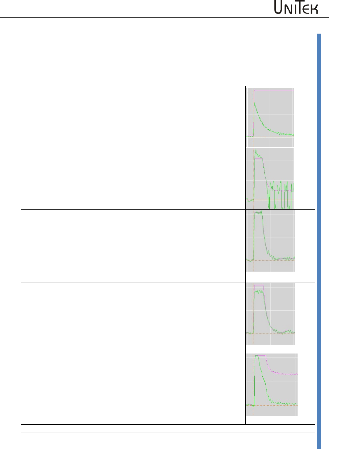
Parameter
Software – Manual N-Drive 3xx
Version 2017 / V1
58
Current controller parameters
Setting of the current controller amplification
The current controller parameters may only be modified by trained and skilled personal. Setting the
current controller is only necessary for unidentified motors. Preset a step function for free-running
motors. View the current command value (I cmd) and the actual current value (I actual) at the
oscilloscope. The actual value must always be smaller than the command value.
Setting of the parameter (Current, Kp, Ti, TIM)
KP value too small
The difference between the current command value (lcmd) and actual current
value (lactual) is to large.
The max. torque is not reached at high speeds.
KP value to high
The actual current value overshoots the current command value.
Rough operation and motor noise.
Correct KP value
Actual current value does not oscillate.
The difference between the current command value (lcmd) and actual current
value (lactual) is optimal (correction error <5 %)
Integral part
Parameter Ti too large.
Integral part
Parameter TiM too small.
The speed is not reached at max. speed and max. current.
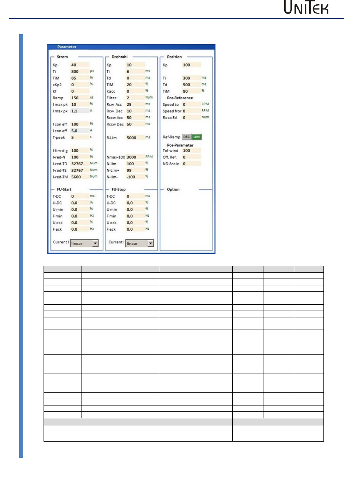
Parameter
59
Version 2017 / V1
Software – Manual N-Drive 3xx
Speed controller parameters
12.5 Speed controller parameters
1 NDrive-Einstellungen-Para-alles-2
Parameter
Function
Setting range
Presetting
Units
Step
ID address
KP
Proportional amplification
0 to 200
50
num
1=0.1
0x2c
Ti
Integration time
1 to 100
10
ms
0.75
0x2d
Tv
Rate time
1 to 1000
0
ms
0.75
0x2e
TiM
Max. integration time memory
0 to 100
50
%
1
0x3b
Kacc
Acceleration amplification
0 to 100
0
%
1
0x5b
Filter
Speed - actual value filter
0 to 10
5
Num
1
0x5e
Ramp-sel
Rcw-Acc
Speed command value ramp,
acceleration
0 to 10000
100
ms
0.75
0x35
Rcw-Dec
Speed command value ramp,
deceleration
0 to 10000
100
ms
0.75
0xed
Rccw-Acc
Speed command value ramp,
acceleration
0 to 10000
100
ms
0.75
0x35
Rccw-Dec
Speed command value ramp,
deceleration
0 to 10000
100
ms
0.75
0xed
R-Lim
Min. speed command value ramp
0 to 10000
10
ms
0.75
0xc7
N max 100%
Max. speed (for 32767 Num)
600 to 50000
3000
RPM
1
0xc8
N-Lim
Speed limit
0 to 100
100
%
1
0x34
N-lim +
Positive speed limit
0 to 100
100
%
1
0x3f
N-lim-
Negative speed limit
0 to 100
100
%
1
0x3e
Actual speed value range
Calibration speed n-max
Limiting
Max. value +/-32767 (15Bit-1)
Nmax value set in the parameter
fields = 32767 = 100 %
Limiting via the parameter field
speed with N-Lim
Setting window for the speed
controller parameters
For further settings please refer
to the pages 'speed' and
'oscilloscope'

Parameter
Software – Manual N-Drive 3xx
Version 2017 / V1
60
Speed controller parameters
Setting field for the speed controller
The amplification parameters KP, Ti, Td, and TiM of the speed controller must be adapted to the
drive conditions of the drive and optimized.
(also see MANUAL commissioning instructions)
Amplification parameters
Parameter
Kp
Input for the proportional amplification in the speed controller.
Setting range 0 to 200 (nominal 10 to 80)
Presetting 40
Formula:
Kp too low:
compensation error, bad dynamics, low-frequ. vibrations
Kp too high:
strong motor noise, high-frequency vibrations
Optimize the amplification to min. overshoots.
Ti
Input for the integration time in the current controller.
Integral – time constant
Setting range 150 to 10000 (nominal 600 to 2000)
Presetting 800
Ti too high: low-frequency vibrations
Ti too low: high-frequency vibrations, strong vibration
tendency
Td
Input for the presetting time in the current controller.
Differential – time constant
Setting range 3 to 100ms (nominal 6 to 20)
Presetting 6
Ti too high: high-frequency vibrations, strong vibration
tendency
TiM
Max. value from the integral memory
Setting range 0 to 100% (nominal 20 to 50 %)
Presetting 20 %
If adjusted too low, the speed is not reached.
Kacc
Dynamic acceleration value directly to the current controller.
Setting range 0 to 100 % (nominal 10 to 50 %)
Presetting 0 %
If adjusted too high there is a risk of current oscillations.
Filter
Filter for the actual speed value. Zero without filter, 10 is the
max. filter effect.
Low filter values: motor noise may occur
High filter values: low-frequency vibrations may occur
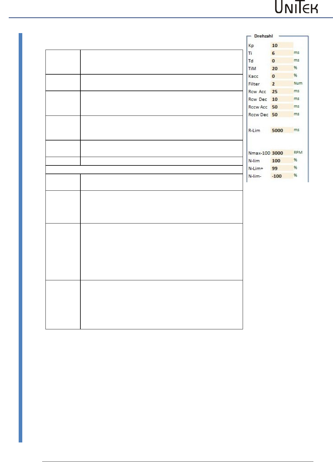
Parameter
61
Version 2017 / V1
Software – Manual N-Drive 3xx
Speed controller parameters
Speed command value ramp
Rcw-Acc
Acceleration ramp, positive direction of rotation for
speed and position control (can be selected for the
reference run)
Rcw-Dec
Deceleration ramp, positive direction of rotation only for
speed control. Set to <10 ms for position control.
Rccw-Acc
Acceleration ramp, negative direction of rotation for
speed and position control
Acceleration ramp for torque control.
Rccw-Dec
Deceleration ramp, negative direction of rotation only for
speed control. Set to <10 ms for position control.
Deceleration ramp for torque control.
R-Lim
Minimum braking ramp at limit switch an emergency stop
(can be selected for the reference run).
Speed limits
N max-
100
Maximum speed. The set value corresponds to the num.
value of +/-32767 equals 100 %.
N-Lim
Speed limiting by means of Nmax, (0 to 99 % of Nmax)
Max. speed setting for position control.
At torque control as speed limiting 0 to 99 %, at 100 %
the speed limiting is not effective.
N-lim+
Speed limiting inferior to Nmax for a positive rotation
direction (0 to 99 % of Nmax)
Activated via logic input N clip (neg&pos)
For electric vehicle
Brake Car Setting on the logic page (digital input):
Current limit for braking current at torque command
value zero
N-lim-
Speed limiting inferior to Nmax for a positive rotation
direction (0 to 99 % of Nmax)
Activated via logic input N clip (neg&pos)
For electric vehicle
Brake Car Setting on the logic page (digital input):
Current limit for braking current at braking switch active.
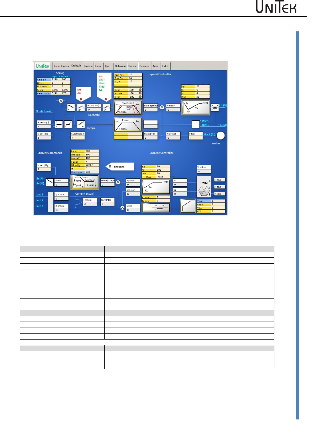
Parameter
Software – Manual N-Drive 3xx
Version 2017 / V1
62
Speed controller parameters
12.6 Speed controller parameters
Page ‘Speed’ (Speed controller)
Schematic diagram with input windows for control parameters and display windows for numerical values
Speed command values
The speed command value is provided by:
ID address
Analog
IN1 / IN2
Analog input 1
0xd5 L / 0xd6 L
Offset
IN1 / IN2
Correction of the zero point error
0x2f L / 0xd7 L
Cutoff
IN1 / IN2
0x50 / 0x53
Scale
IN1 / IN2
Scale for the input value
0x2f H / 0xd7H
Analog int
IN1 / IN2
Processed command value
0xd5 H / 0xd6 H
Dig-Torque
digital torque command value
0x90
Dig-Speed
digital speed command value
0x31
Dig-Cutoff
0x1e
N-Pos
Position controller output Pos->Speed
Actual value
Speed actual
Speed actual value signal
Filter
Filter for the speed actual value
0x5e
N actual
Speed actual value signal for the control
0x30
N act monitor
Speed actual value signal for the display
0xy8
Speed control values
Ncmd Ramp
Speed command value for the control
0x32
N actual
Actual speed value for the control
0x30
N error
Speed command value minus actual value
0x33
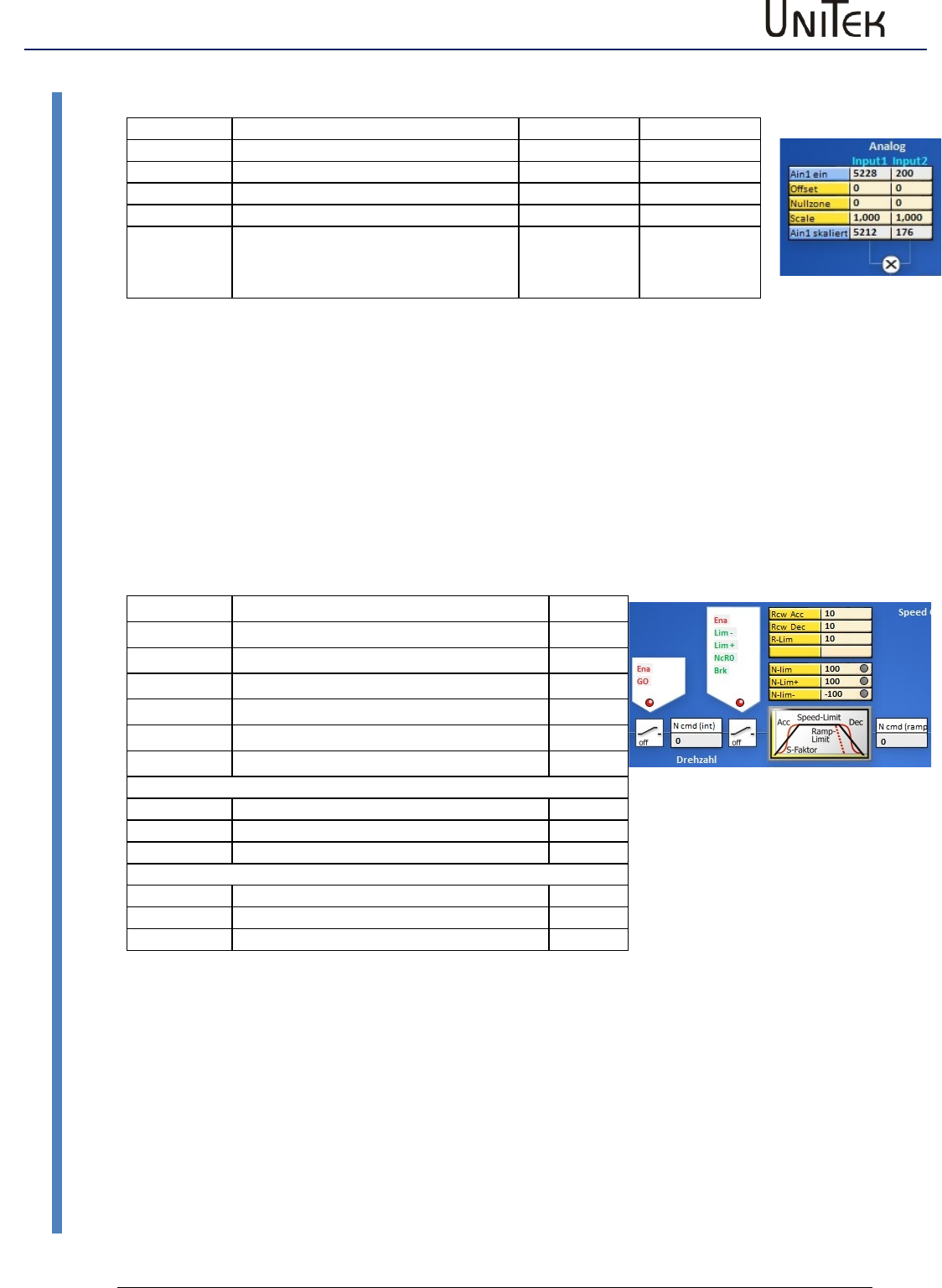
Parameter
63
Version 2017 / V1
Software – Manual N-Drive 3xx
Speed controller parameters
Display input field for analog command values
Parameter
Function
Input 1(Ain1)
Input2 (Ain2)
Ain x on
Terminal voltage in num (32767)
0xd5L
0xd6L
Offset
Offset correction input amplifier
0x2fL
0x2fL
Zero zone
Command value - zero range
0x50
0x53
Scale
Amplification factor
0x2fH
0xd7H
Ain x scaled
Processed command value
Ain x sc. = Ain x on +/- Offset x Scale
0xd5H
0xd6H
Display input field for analog command values
The direct input values of Input1 and Input2 are displayed under Analog IN.
These signals are processed by means of the parameters offset, cutoff and scale. The result is displayed
under ‘Analog int‘.
It is possible to select either the analog or the digital command value by means of the selection switch
‘analog’ and ‘digital’. When both switches are closed, the digital and the analog command value are
added.
The sum at Ncmd must be equal or inferior to 32767 Num.
The digital command values can be entered as digital speed, digital torque, or they are provided by the
position controller (NPos).
Switch field1 (controlled by means of digital inputs)
Command
green function
Enable
Enable hardware+software
GO
Internal enable (output stage)
Lim -
Limit switch minus
Lim +
Limit switch plus
Nc RO
Command value zero
Brake
Brake
Speed - ramps
Rcw Acc
Acceleration ramp right
0x35L
Rcw Dec
Braking ramp right
0xedL
R-Lim
Emergency stop ramp
0xc7
Command value limits
N-Lim
Speed limit inferior to 100%
0x34
N-Lim+
Speed limit right (positive)
0x3f
N-Lim-
Speed limit left (negative)
0x3e
The speed command value is only transmitted (green) at enable (Enable) and internal enable
(GO). It is shown in the display field ‘speed command value‘ (N cmd).
Switching field 2
When the enable (Ena), the limit switches (Lim-, Lim+), not speed=0, and not brake are switched
(green), the speed command value (N cmd) in the setting field (ramp) is processed.
Ramp field
The acceleration ramp (Ramp-Acc), the deceleration ramp (Ramp-Dec), the limit switches
‘emergency stop’ ramp (Ramp-Limit), and the speed limits (speed-limit, N-limit+, N-limit-) are set.
The result is shown in the display field ‘speed command value after ramp’ (N cmd-Ramp).

Parameter
Software – Manual N-Drive 3xx
Version 2017 / V1
64
Speed controller parameters
Speed controller parameters
(Parameters are also on the page ‘settings‘)
Parameters
Address
Kp
Proportional amplification
0x2c
Ti
Integration time (integral part)
0x2d
Td
Presetting time (differential part)
0x2e
TiM
Max. value integral memory (Ti)
0x3b
The actual speed value (speed actual) is displayed after the filter in the field ‘actual speed value’ (N
actual). At the mix point the actual speed value is subtracted from the speed command value.
The result is shown in the display field ‘speed error‘ (N error).
The speed correction error is processed in the speed controller (PID amplifier). The proportional
amplification (Kp), the integral part (Ti), the differential part (Td), and the memory limit for the speed
controller are set.
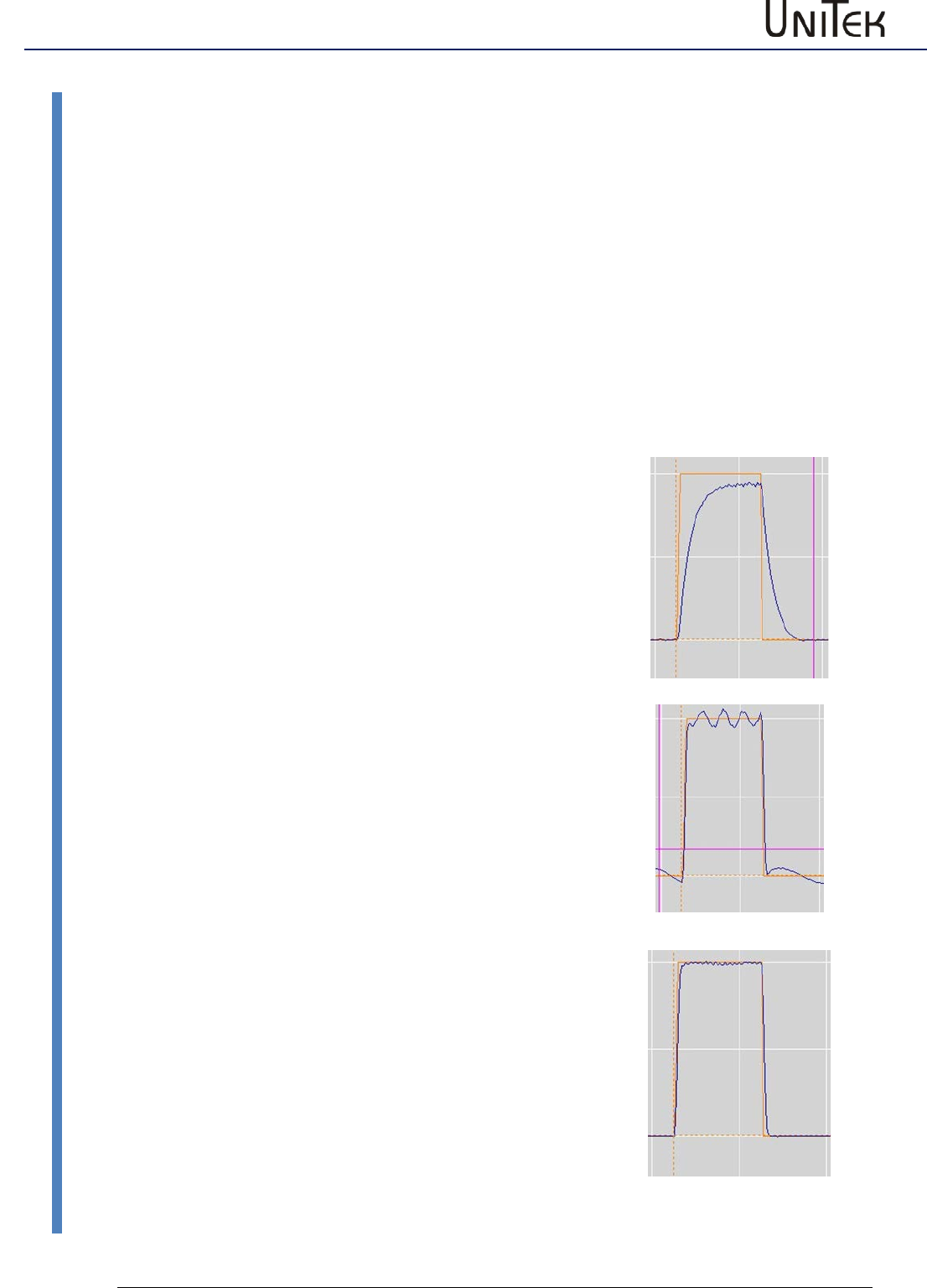
Parameter
65
Version 2017 / V1
Software – Manual N-Drive 3xx
Speed controller optimization
12.7 Speed controller optimization
Setting of the speed controller amplification
The setting of the speed controller is determined by the load, the friction and the inertia
presented by the driven axis.
Preset a step function to optimise the settings by monitoring the response at a step input.
The oscilloscope window incorporates a step generator for testing.
Monitor the speed command value (N cmd-ramp) and the actual speed value (N actual) on the
oscilloscope. For further information refer to the commissioning manual.
Speed controller adjustment of the parameter Kp without integral component (Ti = 0)
KP too low
(Timax = 0)
The difference between the speed command value (Ncmd-
Ramp) and the actual speed value (N actual) is too large.
The speed command value is not reached and the acceleration
is too weak.
The drive reacts smoothly to command value changes and it
can be rotated at standstill.
KP too high
(Timax = 0)
The actual speed value overshoots the speed command value
significantly.
Rough operation, strong tendency to vibrations (even at
standstill), and motor noise.
Correct KP value
(Timax = 0)
The difference between the speed command value and the
actual speed value is optimal (control error approx. < 5%).
Remaining errors can be eliminated by means of the integral
adjustment.
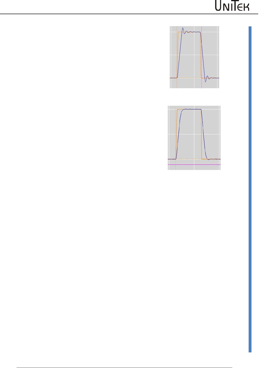
Parameter
Software – Manual N-Drive 3xx
Version 2017 / V1
66
Speed controller optimization
Speed controller setting parameters Kp, Ti und TiM
Setting integral part (optimal Kp value)
Ti value too low
Short overshoots with tendency to high-frequency oscillations.
Ti value too high
Long overshoots with tendency to low-frequency oscillations.
Adjust the correction error (overshooting) to minimum by
means of the parameter TiM. Select the Tim value as small as
possible.
Optimally set speed controller
Kp value, Ti value are optimal
No overshooting of the speed.
TiM value optimal
There is no speed error occuring.
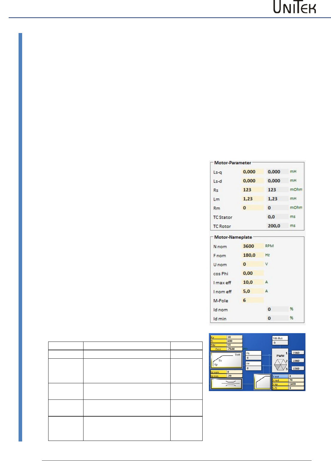
Field weakening at synchronous motors
67
Version 2017 / V1
Software – Manual N-Drive 3xx
Field weakening mode
13 Field weakening at synchronous motors
13.1 Field weakening mode
The field weakening mode at synchronous motors with surface magnets is only possible within a
small range (max factor 1.2) and thus, not economically viable.
At synchronous motors with integrated magnets (salient-pole machines) it is possible to achieve
speed ranges up to the factor 4. At optimal rating the motor and the servo can in this case be
dimensioned smaller.
Note:
If the field weakening (power supply switch-off, error switch-off, etc.) fails at max. speeds, the
motor can generate high induced voltages.
For devices connected to the power supply the threshold voltage is 400 V or 800 V. For battery-
driven devices the counter voltage must always be inferior to the battery voltage.
If the devices or batteries have no external protective circuit they may be destroyed in case of
motor overvoltages.
Presettings
Motor dates
Setting parameters - Field weakening
Parameter
Address
Id nom
nominal Id-current 100 %
0xb2
Id min
min. Id-current -50 to -80 %
from set current at motor
I nom eff
0xb5
V red
Output voltage for the field
weakening (90 to 50 %)
0x8b
V Kp
Control amplification for the
field weakening (500-2000)
0x8c
V Ti
Rated time field control
(0-2000)
Note: tendency to oscillate
0x8d
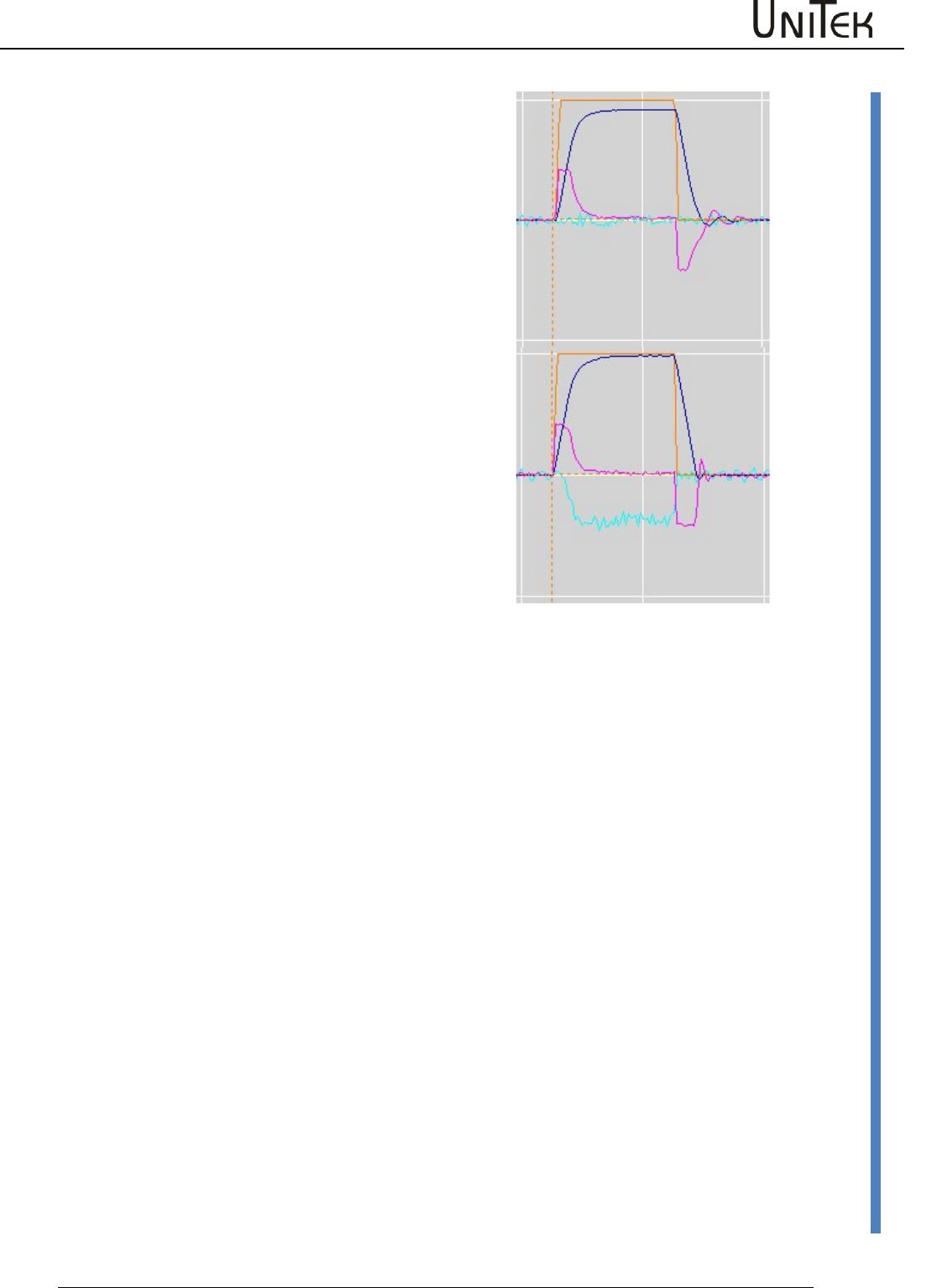
Field weakening at synchronous motors
Software – Manual N-Drive 3xx
Version 2017 / V1
68
Field weakening mode
Without field weakening
The speed (blue characteristic) is not reached at max.
output voltage.
Id –current (light blue characteristic) is controlled to
zero.
After the acceleration to the braking (idle speed
operation) the Iq –current (red characteristic) is at a low
value.
With field weakening
The speed (blue characteristic) is reached.
Id-current (light blue characteristic) is compensated
during the field weakening.
At motors with surface magnets a high Id current flows
for only a small increase in speed.
After the acceleration to the braking (idle speed
operation) the Iq –current (red characteristic) is at a low
value.
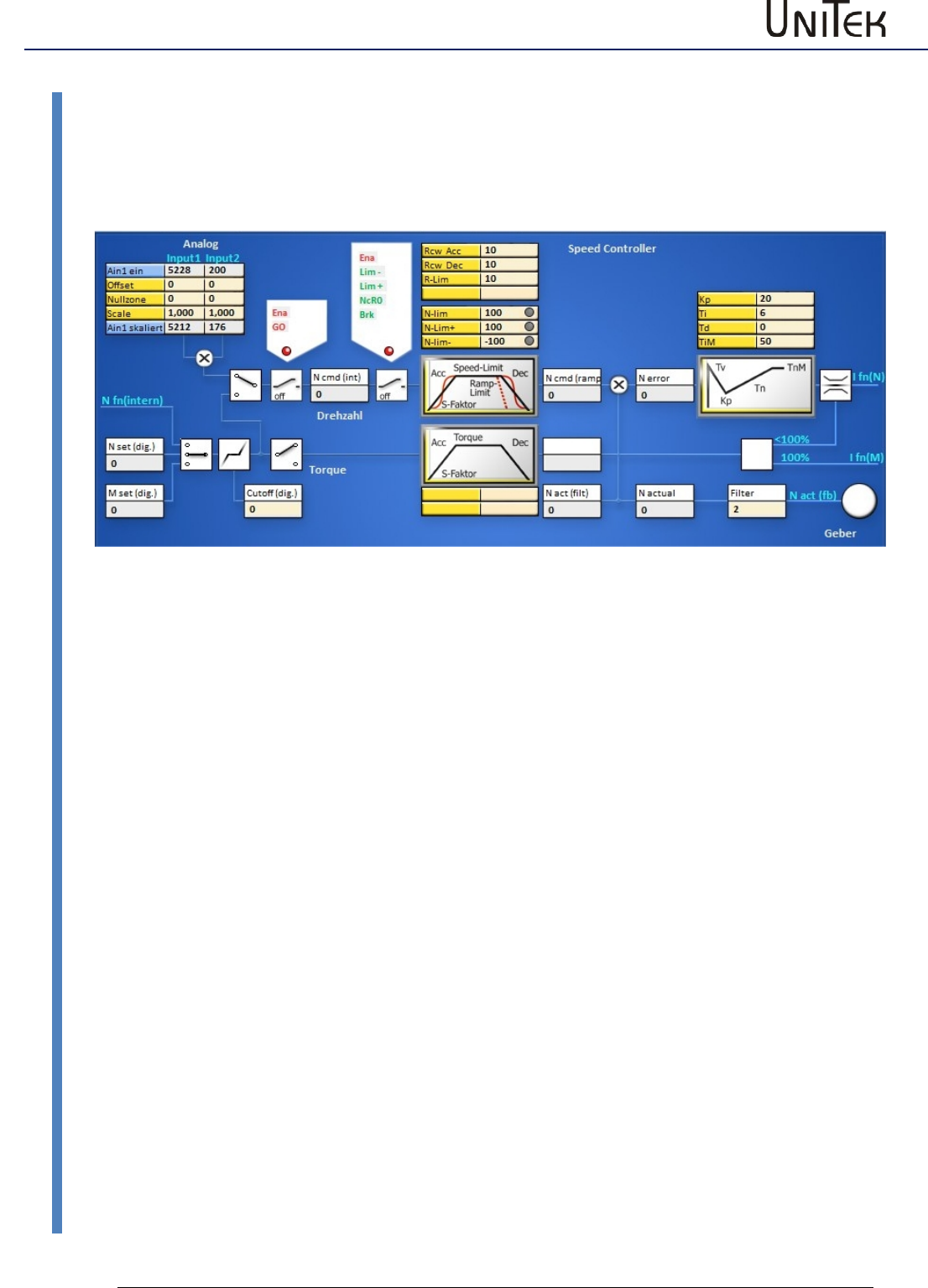
Torque control
69
Version 2017 / V1
Software – Manual N-Drive 3xx
Torque control
14 Torque control
14.1 Torque control
Analog or digital command value as torque command value.
Analog command value 10 V or digital command value (0x90 = 32767num) correspond to 100 %
Imax
The torque command value signal is directly transmitted to the current converter via the torque
ramps (M R-Acc, M R-Dec).
When there is no speed limiting (N-lim 100) the idle speed is only limited by the max. voltage.
When the speed limit < 99 % the speed controller starts limiting.
Analog 1 skaliert or M set (dig) display the torque command value.
Ncmd and Ncmd (ramp) display the numerical value of the limiting (0..99 %=0..32350)
Amplification parameter in the speed controller Kp> 20, Parameter TiM =0 (no integral value)
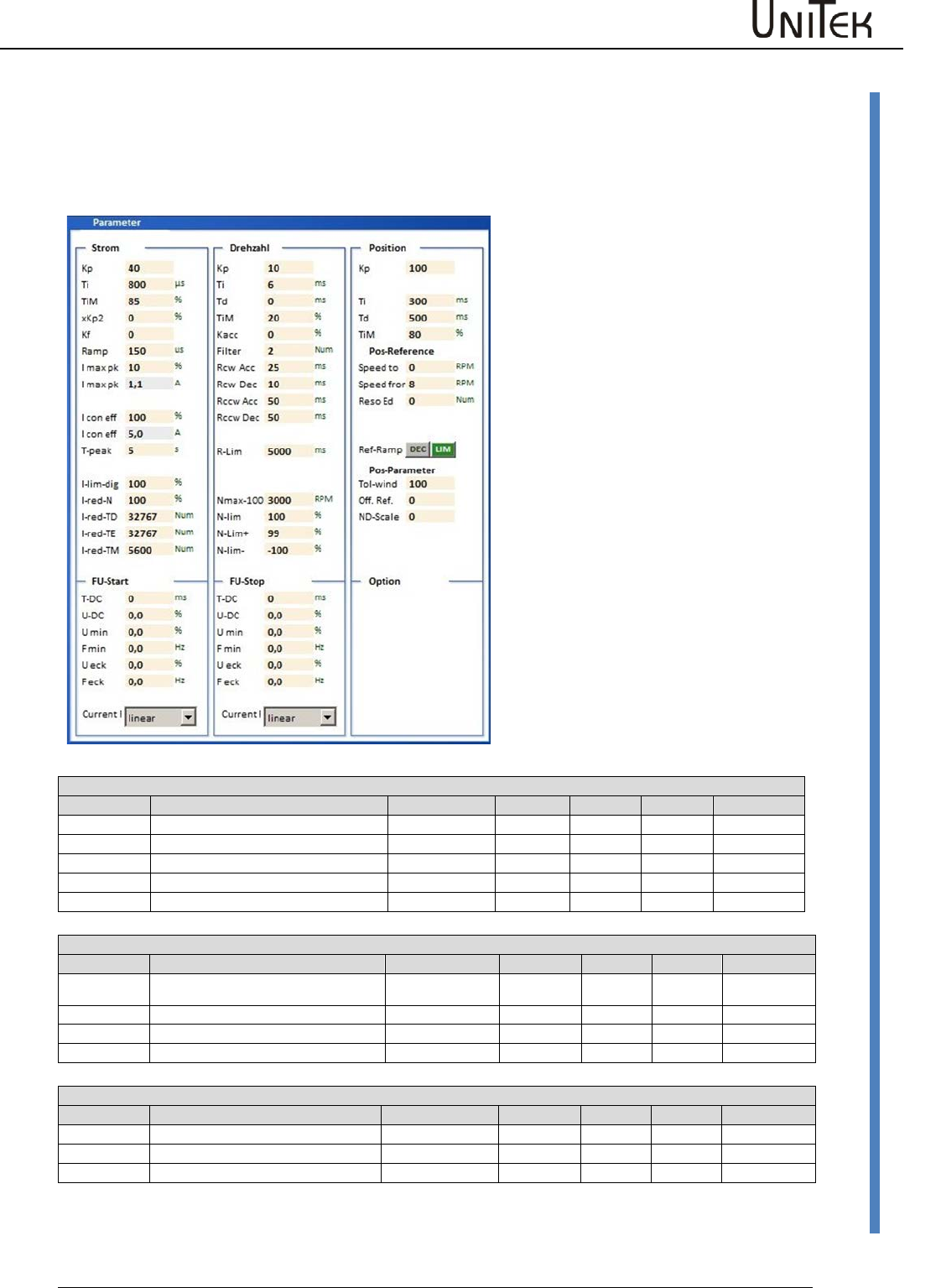
Position controller parameters
Software – Manual N-Drive 3xx
Version 2017 / V1
70
Setting of the position controller
15 Position controller parameters
15.1 Setting of the position controller
Position speed
Parameter
Function
Setting range
Presetting
Units
Step
ID address
Kp
Proportional amplification
0 to 200
70
num
1=0.1
0x6a
Z Factor
Ti
Integration time
1 to 100
0
ms
0.75
0x6b
Tv
Rate time
1 to 1000
0
ms
0.75
0x6c
TiM
Max. integration time memory
0 to 100
0
%
1
0x71
Reference position
Parameter
Function
Setting range
Presetting
Units
Step
ID address
Speed to
Speed compared to the reference
position
10 to 32000
3000
num
1
0x76
Speed from
Loop speed
10 to 2000
500
num
1
0x77
Reso Ed
0x75
Dec-Ramp
Switching of 'ramp acc' or 'limit'
0x78
Parameter position
Paramter
Function
Setting range
Presetting
Units
Step
ID address
Tol window
Window - position message
0 to 2000
100
num
1
0x79
Ref- Off
Zero offset
0 to +/-32676
0
num
1
0x72
ND-Scale
Setting window for the position
controller parameters.
For further settings please refer to the
pages 'position' and 'oscilloscope'.
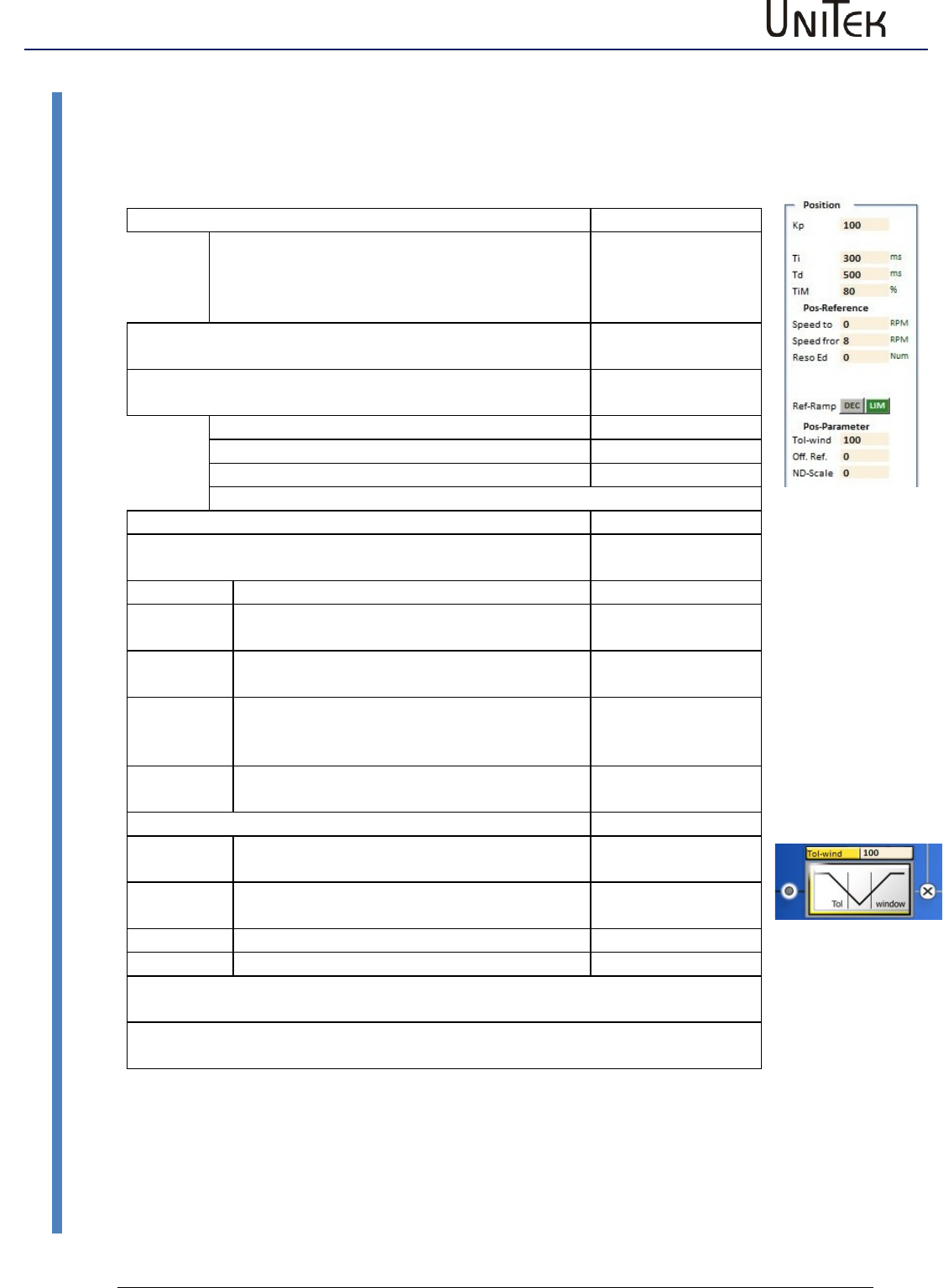
Position controller parameters
71
Version 2017 / V1
Software – Manual N-Drive 3xx
Setting of the position controller
Pos->Speed
The amplified position error is the speed command value.
Proportional control amplification
Address
KP
Proportional amplification position control
circuit.
Determines the slope of the deceleration ramp.
Formel
0x6a
Note: The position control is switched off when no KP-vaue
is entered.
Dynamical control amplification
(only effective in the target range)
Ti
Integral part
0x6b
Td
Differential part
0x6c
TiM
Threshold value integral part
0x71
Pos reference run
The zero point of the incremental measuring system is
determined by means of the reference run.
Speed to
Speed to the limit switch. The limit switch is
passed depending on the speed.
0x76
Speed
from
Reverse speed back to the zero pulse. (loop
speed)
0x77
Reso Ed
0x75
Ref-Ramp
The ramp of the reference run is selected
from the ramps RCW-Acc and Ramp-lim.
Selection
Pos parameters
Tol
window
Position tolerance window (numerical value)
0x79
Reference
Offset
Mechanical zero offset (numerical value)
0x72
ND-Scale
0x7c
One motor revolution corresponds to the numerical value of 65536.
The position command values or the parameter values which are sent from the
control via RS232 or CAN are immediately processed.
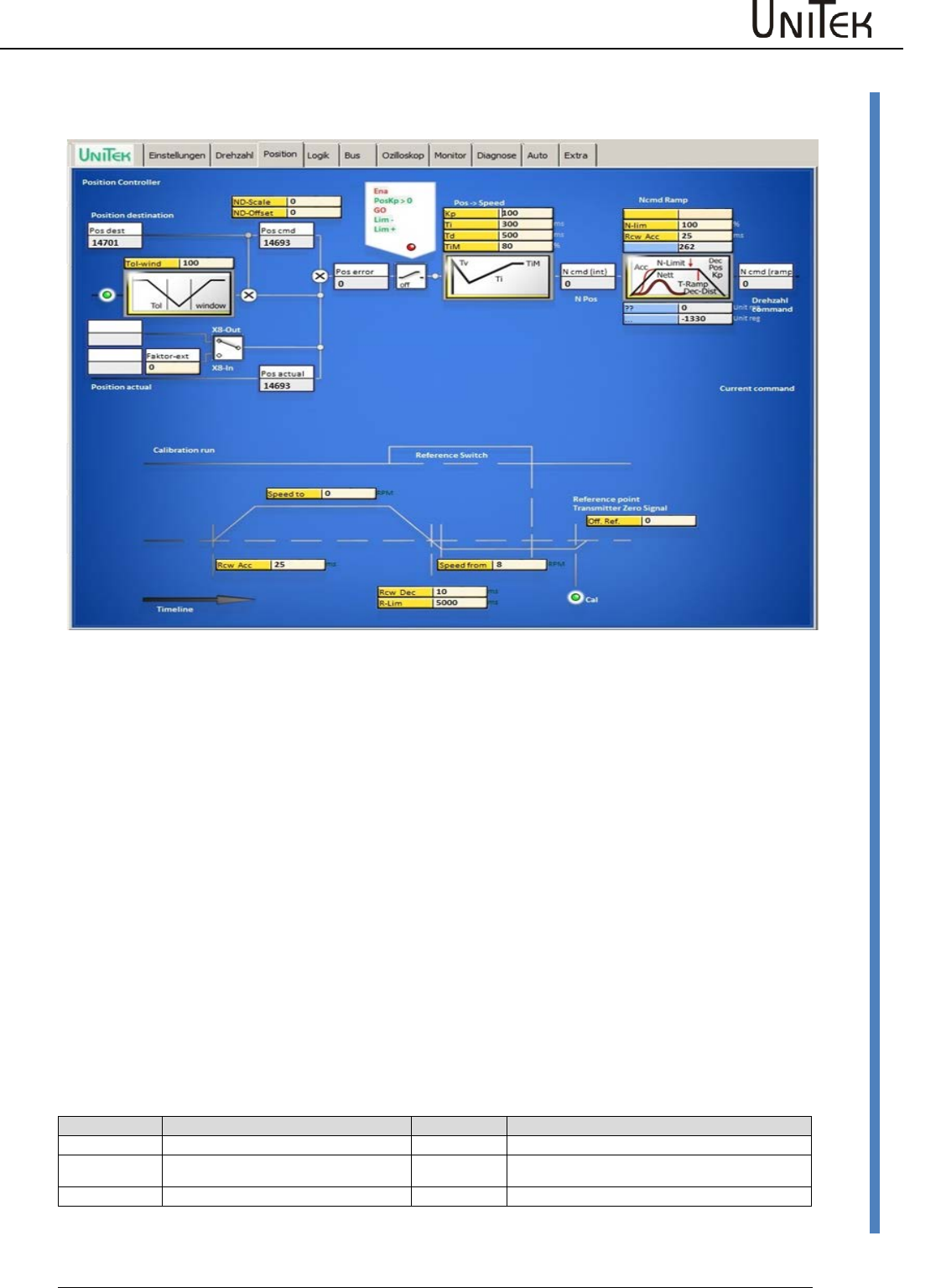
Position controller parameters
Software – Manual N-Drive 3xx
Version 2017 / V1
72
Setting of the position controller
Position setting window
Position controller
Block diagram with the input fields for the control parameters and display fields for numeric
values.
The position error Pos error is calculated at the summing point by subtracting the actual position
value (pos actual) from the position target value (pos dest). If the error is inferior to the adjusted
tolerance value, this state will be displayed in the field 'tol'. At enable the position target value
(pos dest) is proceeded as position command value (pos cmd). The position error is calculated at
the summing point by subtracting the actual position value (pos actual) from the position
command value (pos cmd). The resulting error value is displayed in the field 'speed error' (N
error).
When the enable states (Ena, GO), the output stage switches (Lim-, Lim+), and the position
control amplification (posKp>0) are active (green), the position error (pos error) represents the
input to the Pos -> Speed and Pos -> Current controllers. For both controllers the proportional
amplification (Kp), the integral term (Ti), the differential term (Td), and the memory limiting for
the integral term (Tim) are adjusted. This results in the current command value (I pos).
Reference run (Referce traverse)
Block diagram with the input fields for the control parameters and display fields for numeric
values.
Settings
Displays
Speed to
Speed to the reference switch
Ramp Acc
Acceleration to speed (ref. switch)
Speed from
Reverse speed from switch to zero
pulse
Ramp Dec
Deceleration to reverse speed
(selection 'dec-ramp')
Offset
Mechanical zero offset
Ramp-Limit
Deceleration to reverse speed limit
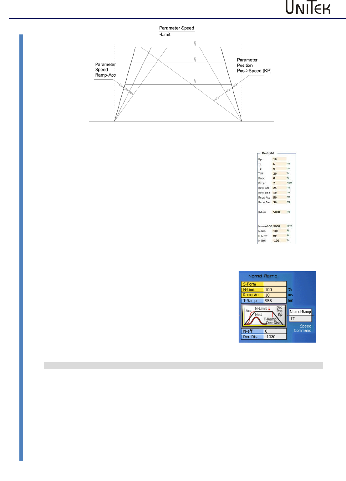
Position controller parameters
73
Version 2017 / V1
Software – Manual N-Drive 3xx
Setting of the position controller
N-Drive2-NDrive-Pos-funktionen
Acceleration:
Rcw-Acc
Acceleration time tb to max. speed in ms.
Acceleration a = v / tb
Constant run:
N-Lim
Speed limit < max. speed.
(max. speed (100 %) = 32767 num)
Deceleration:
Rcw-Dec
For position control, adjust to < 10 ms
Setting via the parameter window ‘position’
(Pos->Speed KP).
The slope of the deceleration results from the
proportional amplification.
Deceleration time
T Ramp
(tv) from max. speed (32767 num) to zero,
displayed in ms in the window 'position'
Deceleration a in m/s²
a = v / tv
v = max. velocity in m/s
tv = deceleration time (T Ramp) in s
Example v = 3m/s, tv = 0.261
a = 3 / 0.261 = 11.5 m/s²
Calculating Kp from a given speed and deceleration time
Kp = √ a x 2603 / v
Kp = √ 11.5 x 2603 / 3 = 99.9 %
Ramp target distance
s = v² / s x a
s = 9/ 2x 11.5 = 0.391 m
Conversion of the units for position control
Actual position value range
Resolver
Incremental encoder
Pulses/rpm
Max. value +/-2147483647
(31Bit-1)
65536 pro rpm
65536 pro rpm
Resolution (smallest value)
16 (65536/4096 (12Bit))
65536/Ink x4
Example
Positioning axis
5mm slope/rpm
Travel 1000 mm = 200rpm
200rpm = 13107200
Resolution 65536/4096 = 16
Incremental encoder 2048 inc./rpm
Travelg 1000mm = 200Upm
200rpm = 1638400
Resolution 65536/8192 = 8
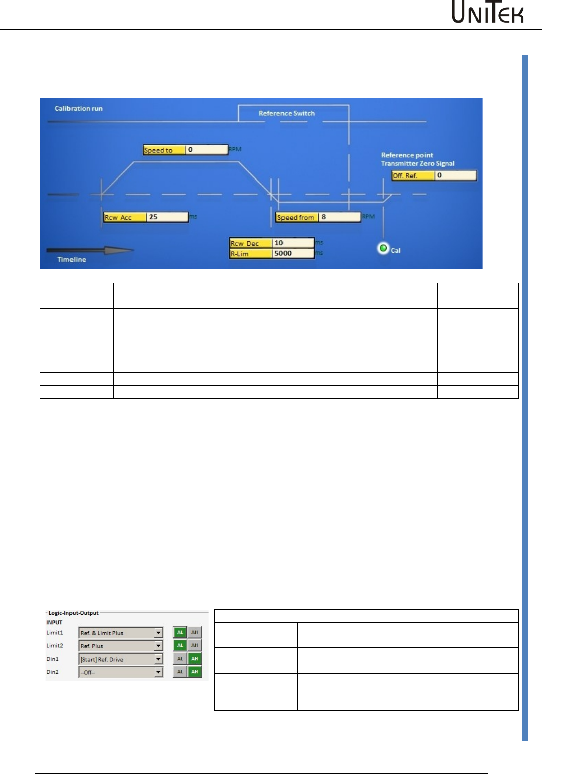
Position controller parameters
Software – Manual N-Drive 3xx
Version 2017 / V1
74
Reference run
15.2 Reference run
A reference run is initiated in order to determine the axis reference position.
Speed to
Speed, moving to the limit switch. The limit switch is passed depending on
the speed.
0x76
Speed from
Speed, reverse run to the limit switch rising edge (Reso) or to the zero pulse
after the limit switch rising edge (Inc.). (loop speed)
0x77
Reso Ed
Correction value at Reso. Enter measurement value ‘zero capture‘
0x75
Dec-Ramp
Set the switch for the ramp at speed reversion from ‘speed to’ to ‘speed
from’.
Selection
Rcw Acc
The ramp programmed at RCW-Acc is used.
0x35 L
R-Lim
The ramp programmed at RCW-Lim is used.
0x7c
The reference switches are selected in the parameter field ‘digital inputs‘. After the machine and the enable
(RUN) are switched on, the reference run (Start Ref Drive) is started via a digit input ( Din1, Din2 ) or the interface
(CAN-BUS, RS232 0x78).
Note:
Driving commands such as Start Ref drive, N cmd , etc. are recognized only after 5ms after the enable.
Close or send the enable first, then send the driving commands.
Reference run
The drive runs to the limit switch at the speed ‘speed to‘, passes the limit switch at loop speed ‘speed from’ and
returns. With a reference switch the drive runs in a positive direction loop, and in a negative direction double
loop. The device position zero point is set after the limit switch rising edge at the incremental encoder zero signal.
At the resolver the absolute value of the position (within half a motor revolution) is saved at the limit switch rising
edge (zero capture).
The mechanical zero point can be shifted in positive or negative direction by means of the parameter ‘Offset’.
Reference switch
Ref&LimitPLUS
Limit switch - positive rotation direction is the
reference switch
Ref&LimitMinus
Limit switch - negative rotation direction is the
reference switch
RefPLUS
The switch rising edge in positive rotation direction
is the reference switch independently from the
limit switches
Via the selection window Dec-Ramp (parameter field servo) the delay is switched from Ramp-Limit to Ramp-Dec
when changing from Speed to to Speed from.
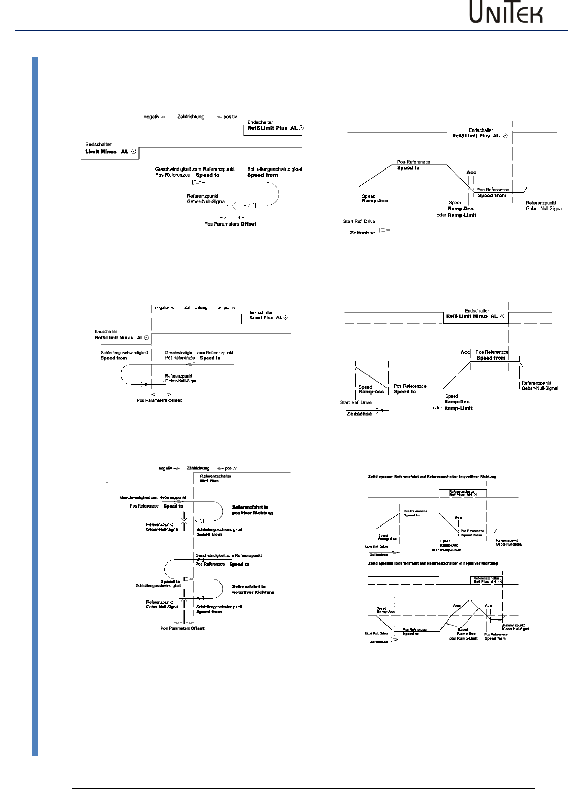
Position controller parameters
75
Version 2017 / V1
Software – Manual N-Drive 3xx
Reference run
Reference run functions
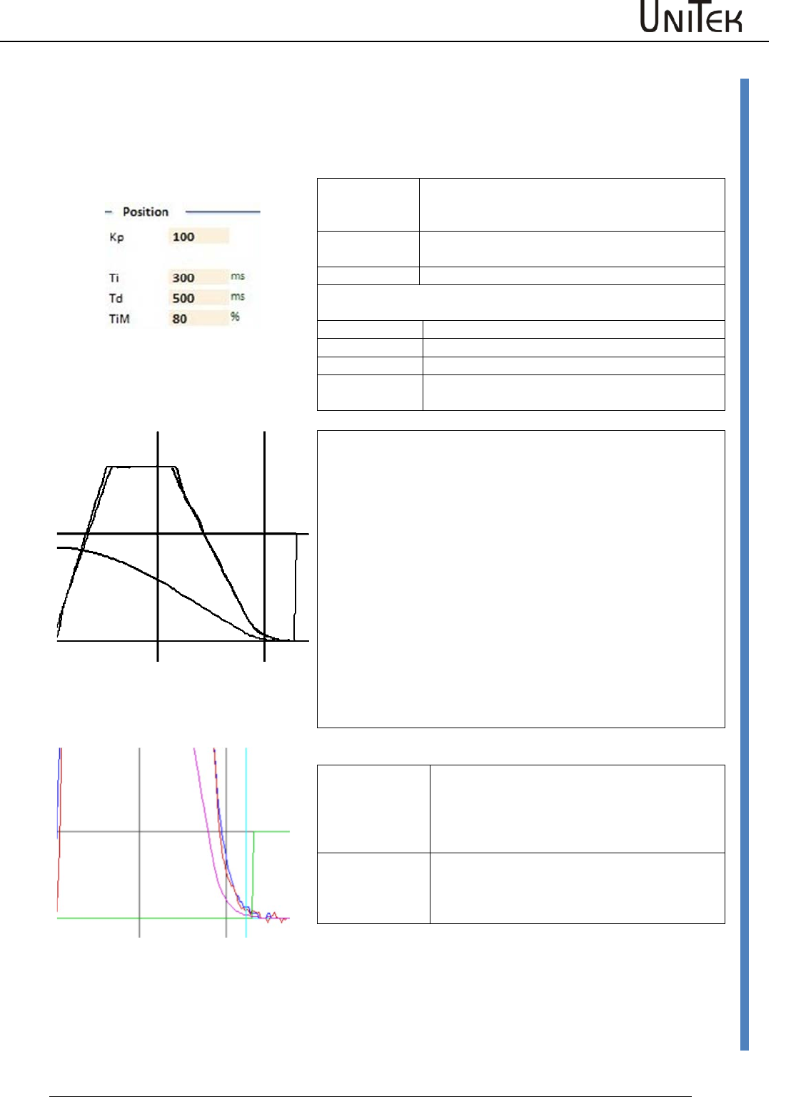
Position controller parameters
Software – Manual N-Drive 3xx
Version 2017 / V1
76
Position controller optimization
15.3 Position controller optimization
Amplification setting Pos->Speed
The amplified position error provides the speed command value.
Proportional control amplification
Kp
The proportional amplification for the position
controller determines the slope of the
deceleration ramp.
Note:
The position control is switched off when no Kp
value is entered.
Dynamic control amplification, (only effective during ramp-up to
final position)
Ti
Integral component
Tv
Differential component
TiM
Threshold value - integral component
T Ramp
Position ramp time, ramp-up to final position,
Delay time (in ms) from max. speed.
Complete presentation
Position run
Acceleration is determined by the parameter Ramp Acc.
A travel at even speed is determined by means of the parameters
Speed Limit.
The ramp-up to final position is determined by the Kp amplification
of the position controller. The deceleration time from 100 % speed
to zero speed is displayed in the field 'T Ramp'.
A small Kp amplification results in a long deceleration ramp. A high
Kp amplification results in a short, steep deceleration ramp. If the
Kp amplification is too high, the axis will overshoot and oscillate in
the target position.
The optimal time ramp is as long as possible and as short as
necessary.
Detailed presentation
Position parameters
Tol window
Position tolerance window (numeric value)
When pos-actual < tol window the output O
Toler is set to 1 and displayed as state 'Tol'
Reference
Offset
Zero position shift (numerical value)
The mechanical zero position is shifted in
positive or negative direction.
One motor revolution corresponds to a numerical value of 65555.
The position command values or parameter values sent from the
controller via the RS232 or the CAN are immediately executed.
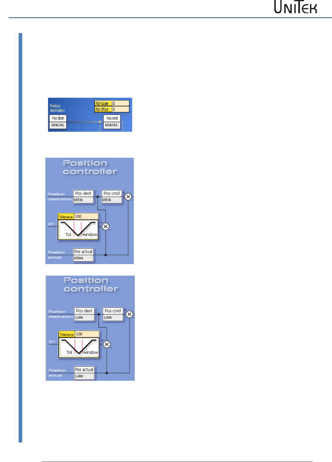
Position controller parameters
77
Version 2017 / V1
Software – Manual N-Drive 3xx
Position scaling
15.4 Position scaling
Display factor for the position values
The display of the values for Pos dest, Pos cmd, and Pos actual is adjusted by means of the
parameter ND-Scale (0x7c, Pos-display factor) in the window 'position'.
At zero the display corresponds to the numerical value (1 motor revolution = 65536 num).
Adaption of the display to the feed value
Calculate the conversion factor necessary for converting the feed
distance to motor revolutions.
For the display this factor must be multiplied by the constant
65536.000 (corresponds to 1.000 mm per revolution).
Example: distance in mm
Slope 5 mm
Gear i=20
Conversion factor for one revolution 1/5 *20 = 4
Position display factor 65536.000* 4 = 262144.000
NDrive scale = 262144.000
Displayed value in mm for Pos dest, Pos cmd, and Pos actual
Example: angle in degree
Transmission: 1 degree = 10 motor revolutions
Conversion factor for one revolution = 10
Position display factor 65536.000* 10 = 655360.000
NDrive scale = 655360.000
Displayed value in degree for Pos dest, Pos cmd, and Pos actual
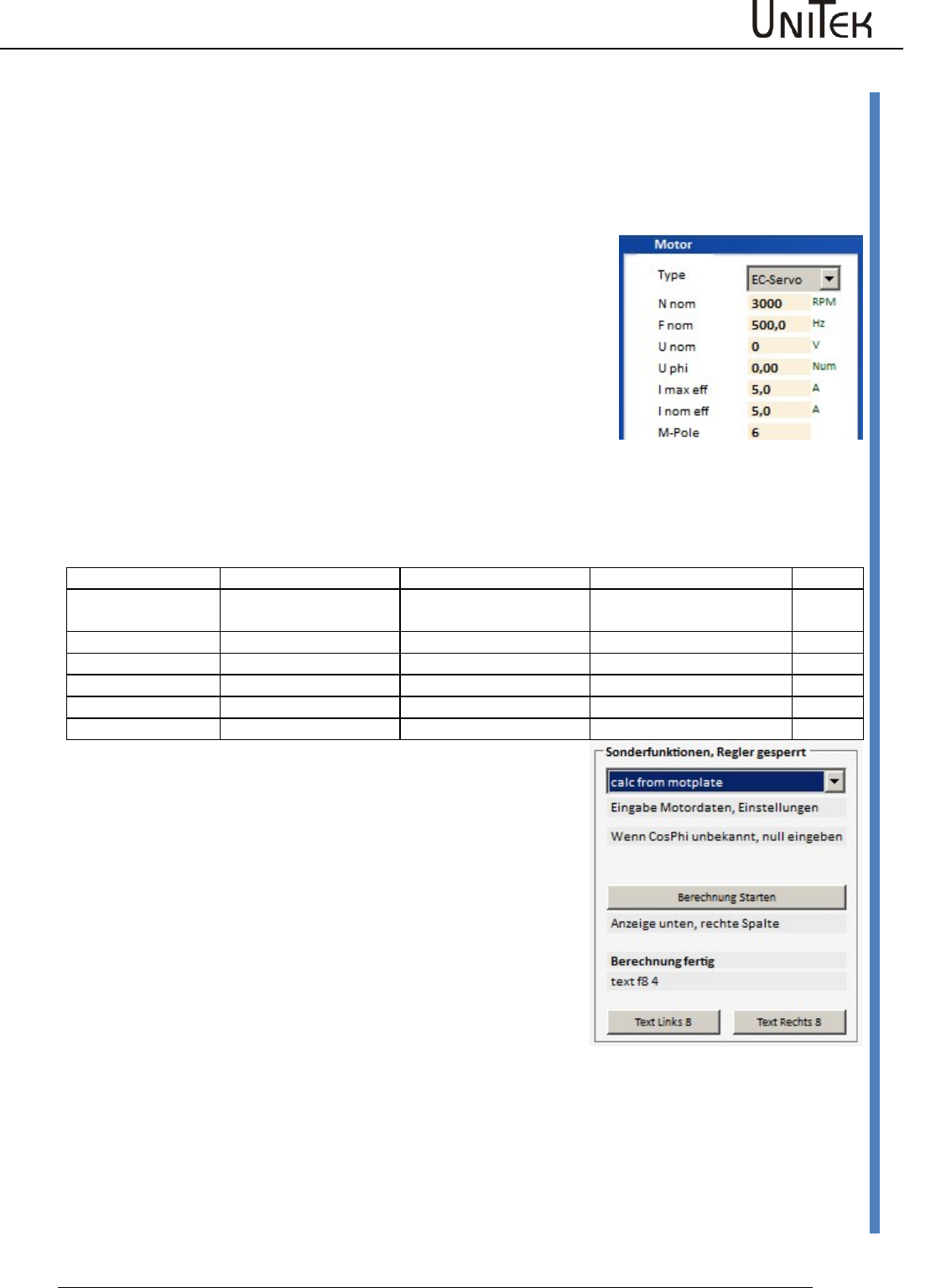
Frequency converter parameters
Software – Manual N-Drive 3xx
Version 2017 / V1
78
Position scaling
16 Frequency converter parameters
Frequency control without feedback encoder
Setting field for the frequency converter in the field motor
motor values(FU)
For standard motors with mains operation the data for 50/60 Hz
operation and star-delta circuit are often written on the type plate.
These data are internationally standardized.
For motors with converter mode the rated operating point is at a
fixed frequency, usually above the 50/60 Hz power supply
frequency.
Further data are not always completely indicated by the
manufacturers.
Partly the rated speed at the rated operating point (rated
frequency, rated load) is not indicated or cosphi is not indicated.
Partly the values are unclearly specified, e.g. voltage refered to
phase to phase (terminal voltage) or the phase voltage (terminal to
star point) or dc bus voltage. Please check the manufacturer data
and dimensions carefully (V, VAC, VDC, A, Arms, etc).
Rated data
Designation NDrive
Motor example 50Hz
Motor example 60Hz
Dim.
Power supply
frequency
Fnom
50
60
Hz
Rated power
0.56
0.63
kW
Rated voltage
Unom
220-240, 360-420
255-275, 440-486
V
Rated current
Inom
2.33-2.25, 1.35-1.30
2.26-2.18, 1.30-1.26
A
Rated speed
Nmom
2820
3385
rpm
Cosphi
Cosphi
0.85
0.85
By means of the drive internal function ’calc from motplate’ and
using the above mentioned rated data it is possible to determine
further values for the motor model.
(Page ‘Auto’ in NDrive or see table further below).
The updating of the display in the NDrive is effected during the
offline-online process. (Switch off and on again the RS232
communication.)
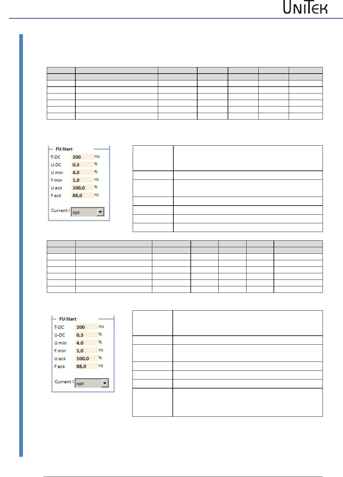
Frequency converter parameters
79
Version 2017 / V1
Software – Manual N-Drive 3xx
Frequency converter parameters
16.1 Frequency converter parameters
Setting window for the frequency converter control parameters
Parameter
Function
Setting range
Presetting
Unit
Step
Id address
FU start
T-DC
Pre-magnetization time
10 to 2000
250
ms
1
0x07 L
U-DC
Pre-magnetization dc voltage
0 to 20
5
%
1
0x08 L
U min
Minimal voltage (boost)
0 to 100
10
%
1
0x0a L
F min
Minimal frequency
0 to 100.0
10,0
Hz
0.1
0x0b L
U eck
Maximale voltage
0 to 100.0
100.0
%
0.1
0x0c L
F eck
Frequency at max. voltage
1 to 1000.0
50.0
Hz
0.1
0x0d L
Description FU start
T-DC
Pre-magnetization time
Delay between the switch-on and the start of the
frequency.
U-DC
Pre-magnetization dc value
Umin
Minimal voltage (boost) at motor standstill.
U/F characteristic is raised.
Fmin
Minimal frequency at motor standstill.
U eck
Maximal output voltage at base freuquency.
F eck
Base frequency for a max. output voltage.
Current I
Parameter
Function
Setting range
Presetting
Unit
Step
Id address
FU stop
T-DC
Braking current time
10 to 2000
0
ms
1
0x07 H
U-DC
dc value for the dc braking
0 to 20
0
%
1
0x08 H
U min
Minimal voltage (boost)
0 to 100
0
%
1
0x0a H
F min
Minimal frequency
0 to 100.0
0
Hz
0.1
0x0b H
U eck
Maximale voltage
0 to 100.0
0
%
0.1
0x0c H
F eck
Frequency at max. voltage
1 to 1000.0
0
Hz
0.1
0x0d HL
Description FU stop
T-DC
Braking current time
Delay between the reaching of F-DC and the
switch-off of the current feed.
U-DC
Pre-magnetization dc value
Umin
Minimal voltage (boost) at motor standstill.
U/F characteristic is raised.
Fmin
Minimal frequency at motor standstill.
U eck
Maximal output voltage at base freuquency.
F eck
Base frequency at stop operation
Current I
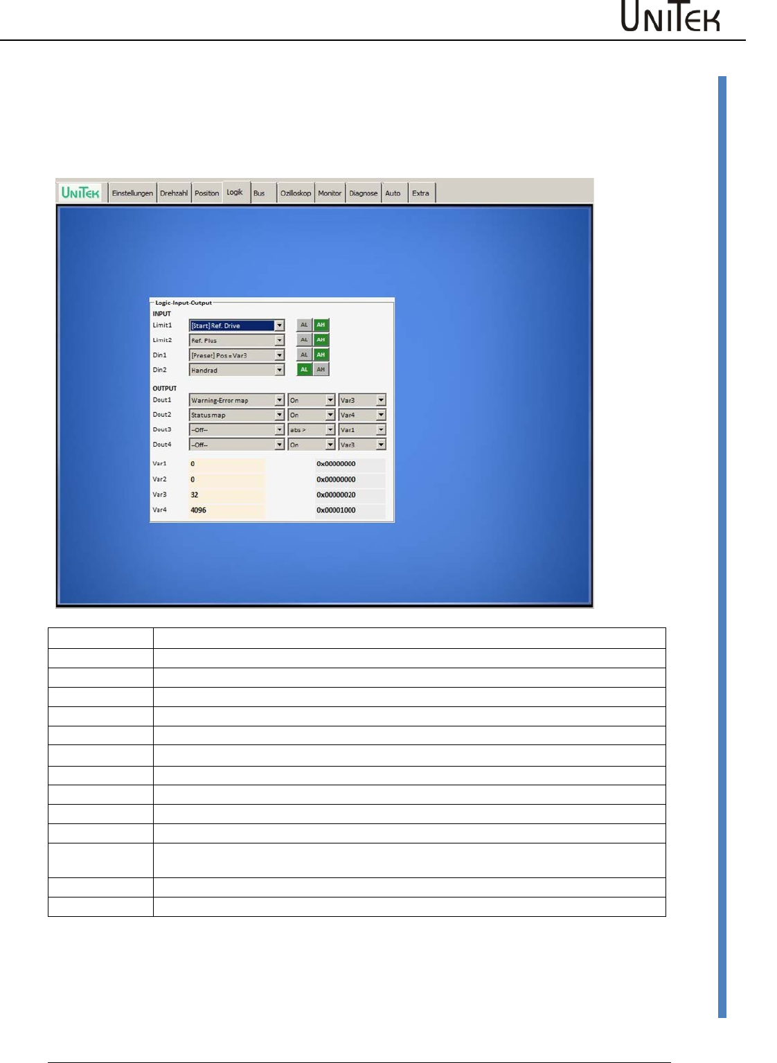
Logic
Software – Manual N-Drive 3xx
Version 2017 / V1
80
Logic setting window
17 Logic
17.1 Logic setting window
Preliminary setting window for digital inputs and outputs
Inputs
Limit1
Programmable digital input, with preference given to an output stage switch and reference switch
Limit2
Programmable digital input, with preference given to an output stage switch and reference switch
Din1
Programmable digital input
Din2
Programmable digital input
Outputs
Dout1
Programmable digital output (operant and comparison variable)
Dout2
Programmable digital output (operant and comparison variable)
Dout3
Programmable digital output (operant and comparison variable)
Dout4
Programmable digital output (operant and comparison variable)
Dout4 is not available for all units
Var1 bis Var4
Comparison variable
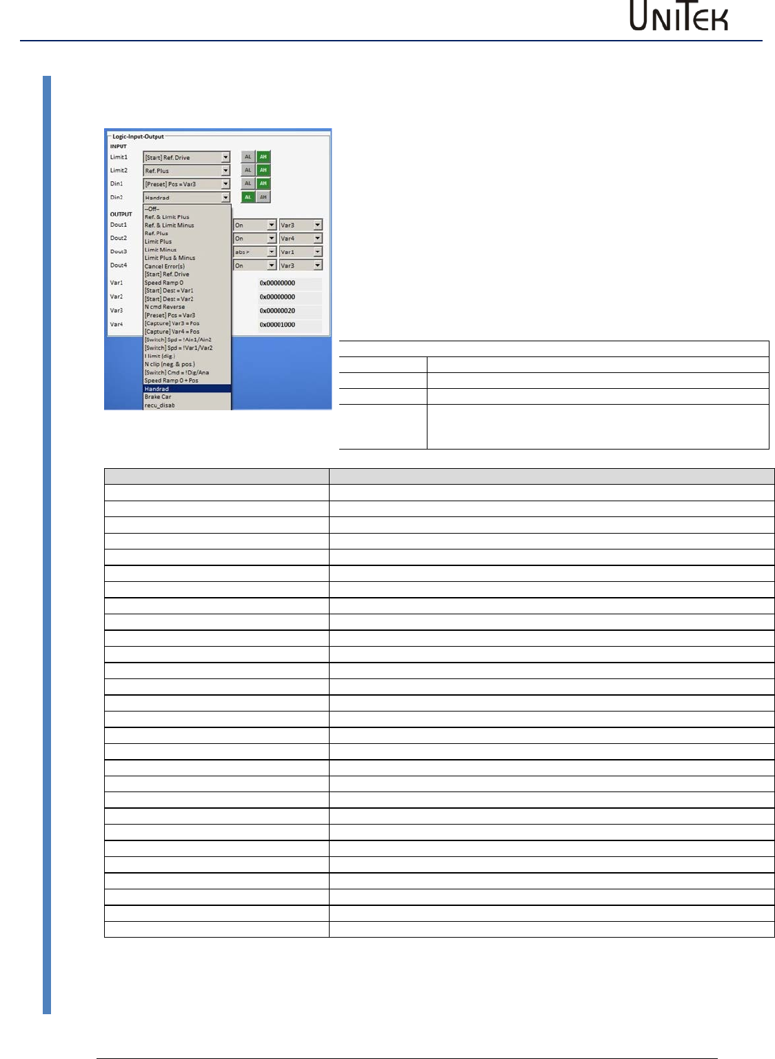
Logic
81
Version 2017 / V1
Software – Manual N-Drive 3xx
Digital inputs
17.2 Digital inputs
Digital inputs
Select function
Click the down arrow to open a drop-down menu showing a list of function
options. Click the required option. The selected function is highlighted in blue and
is transferred to the display field by clicking it.
Select the switching functions
AL = Active Low (e.g. output stage switch)
AH = Active High
Saving
The function is saved in the RAM and activated by pressing the 'enter' key.
The state of the output stage switches inputs Limit1and Limit2 are displayed in
the field 'state' as Lim+ and Lim-..
Example
Digital inputs
Function selected
Limit1
Output stage switch (+) as reference switch (AL active low)
Limit2
Output stage switch (Al active low)
Din1
Start reference travel (AH active high)
Zuordnung-Eingänge
Funktion
Ref & Limit Plus
Limit switch positive direction is also the reference switch
Ref & Limit Minus
Limit switch negative direction is also the reference switch
Ref Plus
Referen ce switch positive direction
Limit Plus
Limit switch positive direction
Limit Minus
Limit switch negative direction
Limit Plus &Minus
Limit switch positive and negative direction
Cancel Error(s)s
Delete error memory
[Start ]Ref Drive
Start reference run
Speed Ramp 0
Speed command value internally switched to 0 (during speed 0 active)
[Start] Dest > Var1
Position variable1 is started
[Start]Dest > Var2
Position variable2 is started
Ncmd Reverse
Command value polarity is switched over
[Preset] Pos = Var3
Actual position value is set to variable3
[Capture] Var 3 = Pos
Sets the variable 3 as position (target) and travels to the position
[Capture ]Var 4 = Pos
Sets the variable 4 as position (target) and travels to the position
[Switch] Spd Ain1 / Ain2
Switching-over command ‘command value Ain1 or Ain2‘
[Switch] Spd !Var1 / !Var2
Switching-over command ‘command value Ain1 or Ain2‘
I limit (dig)
Current limiting to I limit
N clip (neg & pos)
Speed limiting to N clip
[Switch]Cmd = !Dig/Ana
Addition command value digital +analog setting Command Mode Digi+Ana Speed
Speed Ramp 0 +Pos
Hand wheel
Incremental command value from the hand-wheel encoder (2nd counter input)
Brake Car
Regenerative braking function Current setting at N-Lim+ and N-Lim-
recu_disab
Regenerative braking function switched off
rising bank1,falling bank2
PARA_UPDATE
[Start] Dest = Var1,2,3,4
Pos_kombi
[Start] cw = Var1,2,3,4
Cw_kombi
The inputs End1, End2 (Limit1, Limit2) are default set to output stage switch function.
However, it is possible to assign them to any of the input functions Din1, Din 2 available.
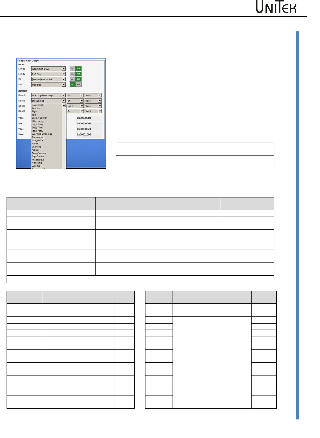
Logic
Software – Manual N-Drive 3xx
Version 2017 / V1
82
Digital outputs
17.3 Digital outputs
Digital outputs
The parameter selected in the first column of the drop-down menu are
compared with the variables in the third column by means of the
operands (second column).
The logic result of the comparison is given at the selected digital output
as low (<1 V) or high (>10 V) value..
Click the arrow keys to open the drop-down menu. Select the
assignment. The selected function is highlighted in blue and transferred
to the display field by clicking it.
.
The output functions can be modified during operation. The function is
saved in the RAM and activated by pressing the 'enter' key.
Example
Digital outputs
Selected function
Dout1
Current superior to variable 3
Dout2
Speed equal to variable 4
Note
: When inductances are connected (relays, brakes, etc.) connect
an over-voltage protective device such as recovery coils or varistors.
The output driver is switched off in case of over-voltages.
Assignment of the output parameters
(selection)
Function
ID address
I_cmd
Current (I) command value (Speed controller output)
0x26
I_actual
Current(I) actual value
0x20
N cmd Ramp
Speed command value
0x32
N actual
Speed actual value
0x30
Pos cmd
Position command value
0x6e
Pos actual
Position actual value
0x6d
I_error
Current(I) error
0x23
N error
Speed error
0x33
Pos error
Position error
0x70
Brake
Brake control signal
0xF2
All parameters of the list ‘measured value selection' can be assigned to the respective outputs.
Operands
Function
Variable
Function
ID
address
Off
off
0
Logic signal zero
On
on
1
Logic signal 1
1Hzz
Test
VAR1
Numerical value of the entered
variable fields
0xd1
=
equal
VAR2
0xd2
!=
not equal
VAR3
0xd3
>
superior to
VAR4
0xd4
<
inferior to
Ain1
Numerical value of the voltages
across the analog inputs
abs>
Absolut valuesuperior to
Ain2
abs<>
Absolut value inferior to
tol>
Tolerance input TOL-wind
Tol<
Tolerance input TOL-wind
>=
superior or equal to
<=
inferior or equal to
hyst>=
Hysteresis at >=
Hyst<=
Hysteresis at <=
window
Tolerance window +/-25 %
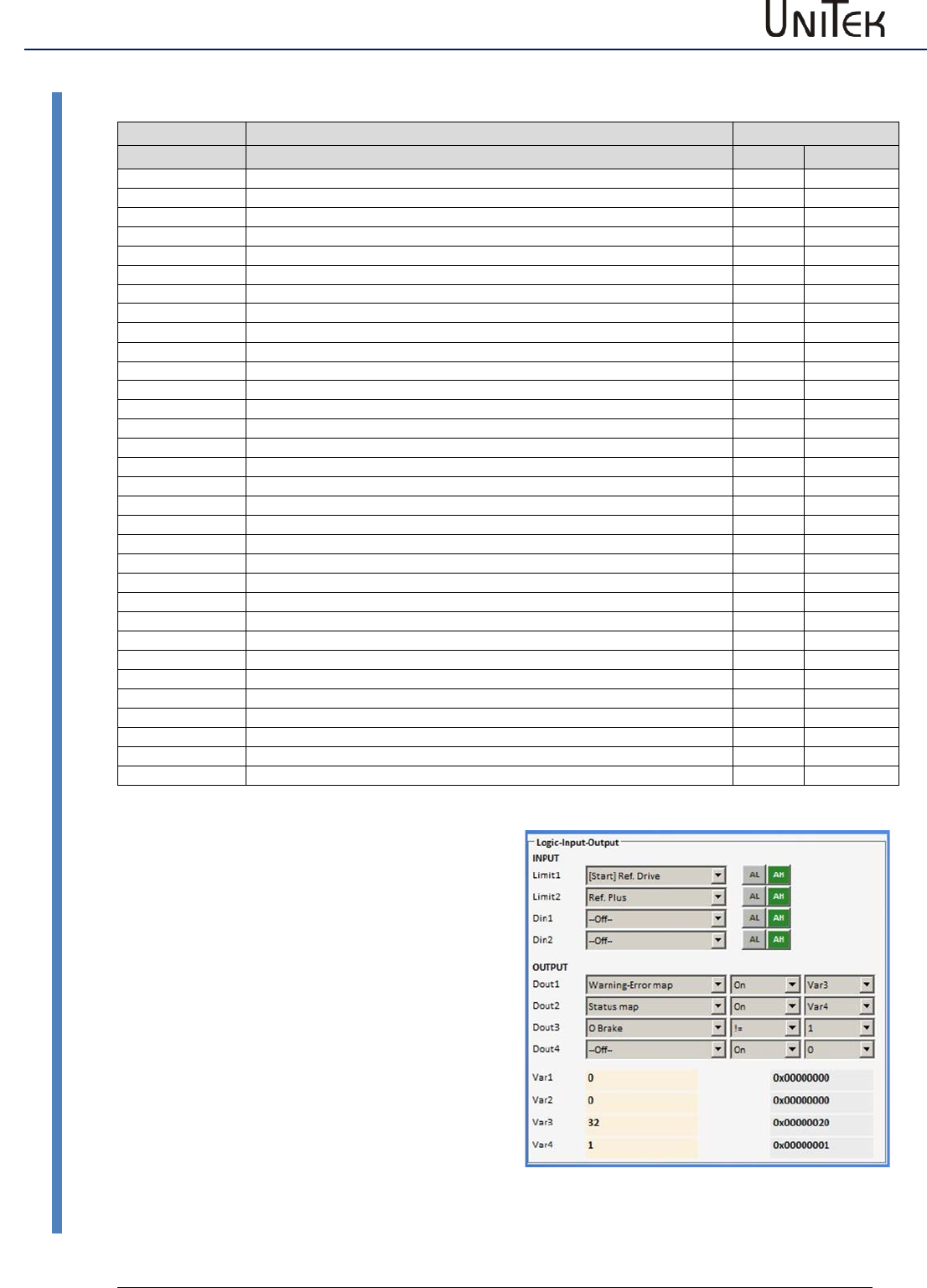
Logic
83
Version 2017 / V1
Software – Manual N-Drive 3xx
Digital outputs
Outputs assigned on Status-Map and Warn-Err-Map
Display of the
Function
ID address
state
0x40
Dec
Ena
Enable drive
Bit 0
1
NcR0
Speed command value = 0 (drive stopped)
Bit 1
2
Lim+
Limit switch plus assigned
Bit 2
4
Lim-
Limit switch minus assigned
Bit 3
8
OK
Drive ok (no uncontrolled control-voltage reset seen)
Bit 4
16
Icns
Current is limited to the continuous current level
Bit 5
32
T-Nlim
Speed-limited torque mode active
Bit 6
64
P-N
Position control possible
Bit 7
128
N-I
Speed control possible
Bit 8
256
<N0
Acutal speed less than 0.1% (standstill)
Bit 9
512
Rsw
Reference switch tripped
Bit 10
1024
Cal0
Calibration move active
Bit 11
2048
Cal
Calibration move completed (position calibrated)
Bit 12
4096
Tol
Position within tolerance window
Bit 13
8192
Rdy
Drive is ready (BTB/TDY contact is closed)
Bit 14
16384
Brk0
De-energized brake with motor active
Bit 15
32768
SignMag
Speed internally inverted
Bit 16
65534
Nclip
General speed limiting (if ≤ 90 %) possible
Bit 17
131072
Nclip+
Additional switchable positive speed limiting possible
Bit 18
262144
Nclip-
Additional switchable negative speed limiting possible
Bit 19
524288
Ird-Dig
Current limiting (switchable) reached
Bit 20
1048576
Iuse-rchd
Actual current limit reached
Bit 21
2097152
Ird-N
Current limited (speed)
Bit 22
4194304
Ird-TI
Current derating (power-stage temperature) possible
Bit 23
8388608
Ird-TIR
Current limited to the continuous current (power-stage temperatue)
Bit 24
16777216
> 10 Hz
Additional current limit if frequency less than 10 Hz
Bit 25
33554432
Ird-TM
Current limit due to motor temperature reached
Bit 26
67108864
Ird-ANA
Current derating due to analog input (if ≤ 90 %) possible
Bit 27
134217728
lwcns
Current peak value warning
Bit 28
RFEpulse
Pulsed RFE-input monitoring active
Bit 29
M+D
free
Bit 30
HndWhl
Hand-wheel function selected
State to digital outputs
Set output (Dout1, 2, 3) onto the Status-Map via
the drop down menu.
Set function to = (inverted on !=)
Select variable.
Select state values (Dec) from the table
(multiple state values possible) and write them
into the selected variable (Var1-Var4).
Example:
Feedback that the drive is enabled.
Output 2
Dout2 , Status-Map , On
Variable Var4
State value Dec=1 (drive enabled)
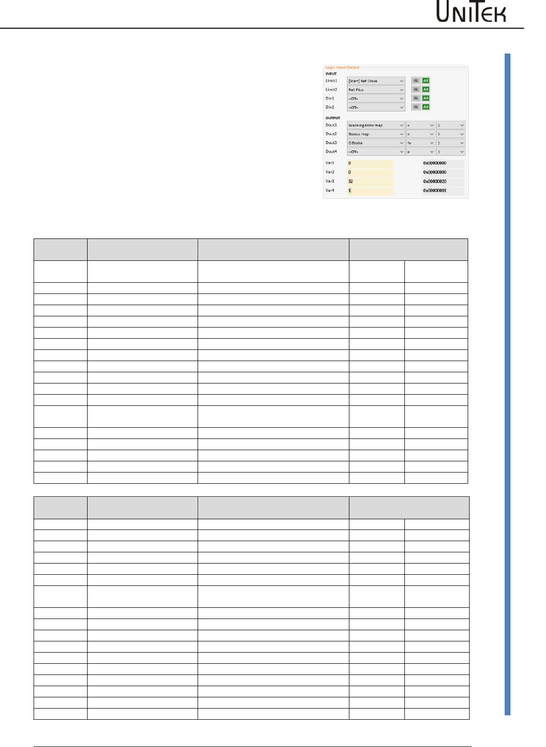
Logic
Software – Manual N-Drive 3xx
Version 2017 / V1
84
Logic links
17.4 Logic links
Fault or warning signals to digital outputs.
Set output (Dout1, 2, 3) onto the Warn-Err-Map via the drop
down menu. Set function to = (Invertiert auf !=). Select
variable. Select Warn-Err values (Dec) from the table (multiple
values possible) and write them into the selected variable
(Var1-Var4).
Example:
Feedback that the power voltage supply is switched on.
Dout1 , Warn-Err-Map , On
Variable Var3
Error value Dec=32 (POWERVOLTAGE , no power supply voltage)
Display on
the servo
Fault message on
NDrive
Description
ID address
NOREPLY-NoRS
RS232 interface not plugged or
disturbed
REGID0x8f
Dec
0
BADPARAS
Defective parameter
Bit 0
1
1
POWER FAULT
Output stage fault
Bit 1
2
2
RFE FAULT
Defective safety circuit
Bit 2
4
3
BUS TIMEOUT
Transmission fault BUS
Bit 3
8
4
FEEDBACK
Faulty encoder signal
Bit 4
16
5
POWERVOLTAGE
No power supply voltage
Bit 5
32
6
MOTORTEMP
Motor temperature too high
Bit 6
64
7
DEVICETEMP
Device temperature too high
Bit 7
128
8
OVERVOLTAGE
Overvoltage >1.8 x UN
Bit 8
256
9
I_PEAK
Over-current 300 %
Bit 9
512
A
RACEAWAY
Racing (without command value,
wrong direction)
Bit 10
1024
B
USER
User - Fault selection
Bit 11
2048
C
I2R
Overload
Bit 12
4096
D
RESERVE
Bit 13
8192
E
ADC-Int
Current measuring fault
Bit 14
16384
F
BALLAST
Overload of the ballast circuit
Bit 15
32768
Display on
the servo
Fault message on
NDrive
Description
ID address
REGID0x8f
Dec
0
WARNING_0
Inkonsistent device identification
Bit 16
65534
1
ILLEGAL STATUS
RUN signal
Bit 17
131072
2
WARNING_2
FE signal inactive
Bit 18
262144
3
Bit 19
524288
4
Bit 20
1048576
5
POWERVOLTAGE
Power supply voltage missing or too
low
Bit 21
2097152
6
MOTORTEMP
Motor temperature > 87 %
Bit 22
4194304
7
DEVICETEMP
Device temperature > 87%
Bit 23
8388608
8
OVERVOLTAGE
Overvoltage >1.5 x UN
Bit 24
16777216
9
I_PEAK
Over-current 200 %
Bit 25
33554432
A
Bit 26
67108864
B
Bit 27
134217728
C
I2R
Overload > 87 %
Bit 28
268435456
D
Bit 29
536870912
E
Bit 30
1073741824
F
BALLAST (unit dependent)
Overload of the ballast circuit >87 %
Bit 31
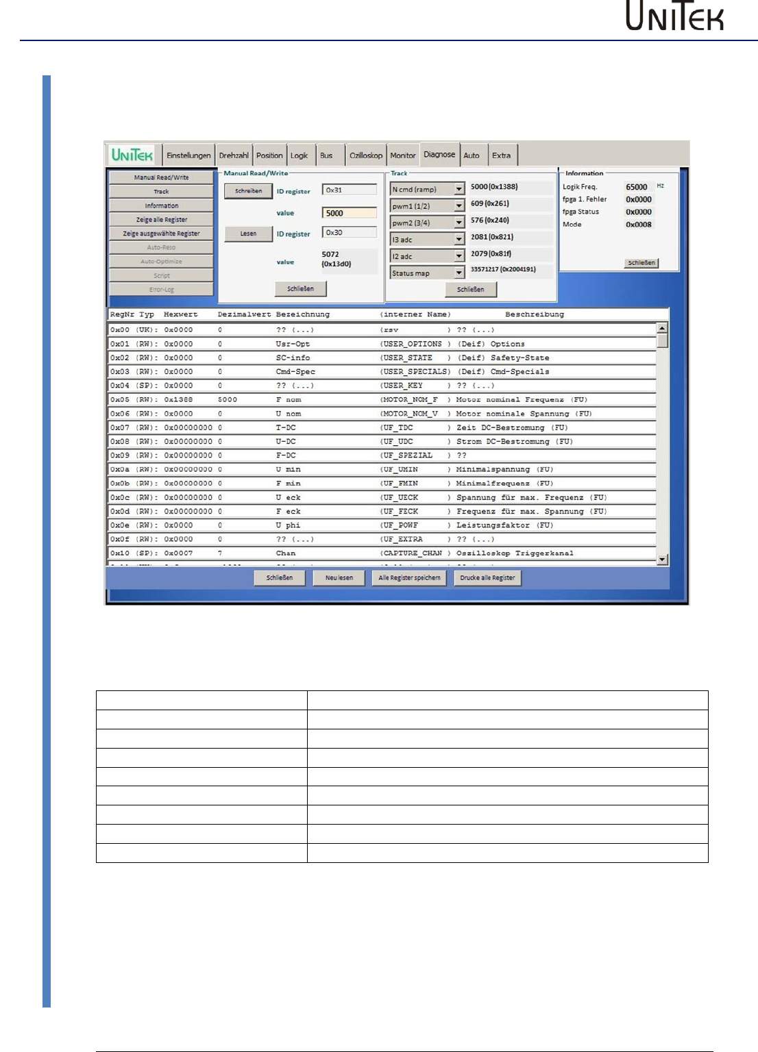
Diagnosis
85
Version 2017 / V1
Software – Manual N-Drive 3xx
Diagnosis window
18 Diagnosis
18.1 Diagnosis window
NDrive-Diagnose-alles-1
Setting window for the diagnosis
Manual Read / Write
Direct read or write of the parameter values
Track
Display of the numeric value of the selected parameter
Information
Information about transfer errors
Zeige alle Register
Parameter list with parameter Ids
Zeige ausgewählte Register
List of all parameters selected and their parameter Ids
Auto-Reso
see page AUTO
Auto-optimize
see page AUTO
Fehler-Historie
not yet implemented
Script
not yet implemented
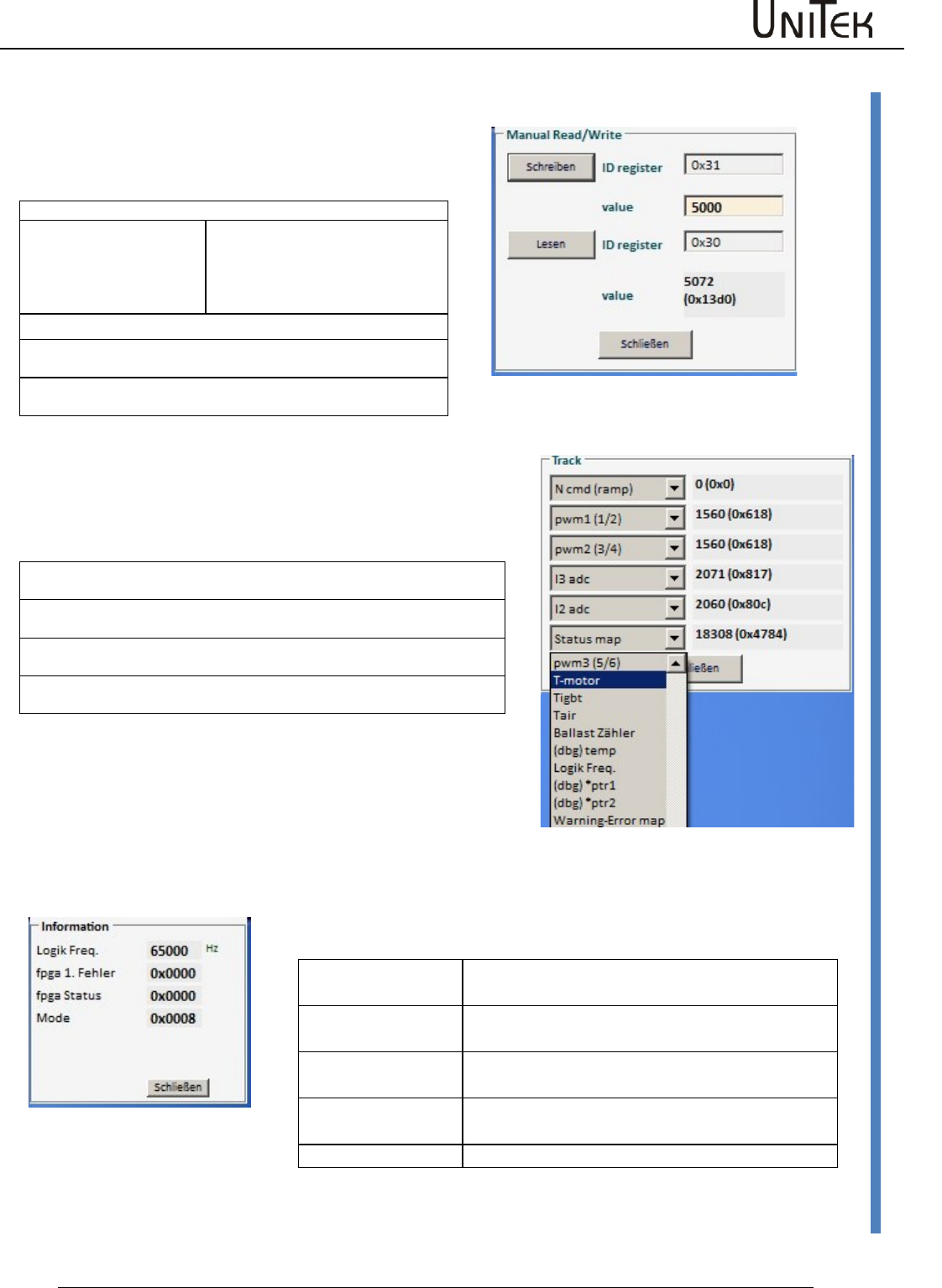
Diagnosis
Software – Manual N-Drive 3xx
Version 2017 / V1
86
Manual read/write
18.2 Manual read/write
Direct reading and entering of the parameter values
Note: only for service!
NDrive-Manual-RW-de-1
Reading parameters:
Enter the parameter address into the input field ID register.
Key lesen
Click it
Below the input field the parameter
designation and its contents is
displayed as numerical and hex
value.
Writing parameters:
Enter the parameter address into the input field ID register.
Enter the value for the selected parameter in the input field Value.
Click key ‘write‘
The parameter values are immediately transferred.
18.3 Track display field
Track
Display of the parameter values
The numerical values and hex values (0x…) of the selected parameters are
displayed in the track display.
Click the arrow key to open the scroll menu for the selection of a parameter
value.
Teh value is selected by means of the arrow keys or the scroll bar in the
scroll field.
The selected value is highlighted in blue. When the value is selected the
scroll field closes.
Note:
Alle parameter values can also be displayed on the
oscilloscope
Information
Display for current states (no input possible)
Foreground
Speed of the foreground program
Motor pos spikes
Actual speed value error
RS232 resync
Transmission error RS232
CAN overruns
Transmission error CAN-BUS
Mode
Mode bit setting
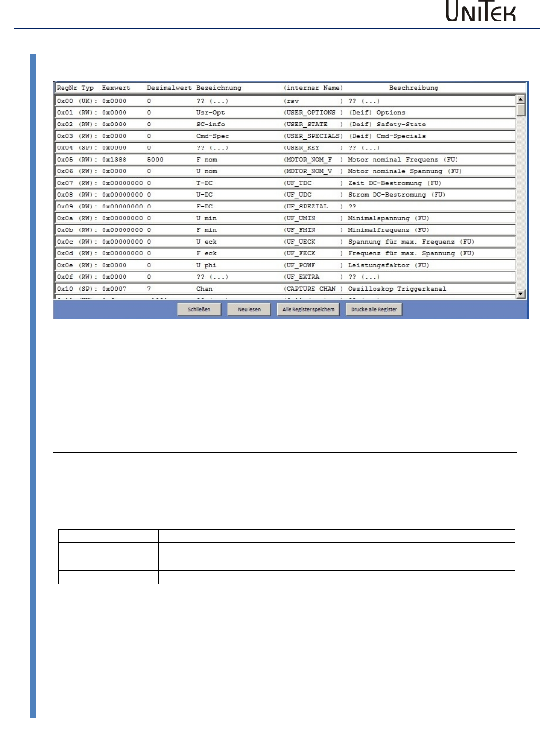
Diagnosis
87
Version 2017 / V1
Software – Manual N-Drive 3xx
Information
18.4 Information
Display field for registers
Show all registers
All 255 registers are shown in a table. The register contents cannot
be modified.
Show selected registers
Only the registers which are important for the user are display in a
table. The registers can be selected via the file ‘Reglist.txt‘.
The register contents cannot be modified.
Selection in the footer
Close
Display field is closed
Re-read
The parameter values are read again from the servo.
Save registers
The displayed registers are written into a file.
Print registers
The displayed registers are printed.
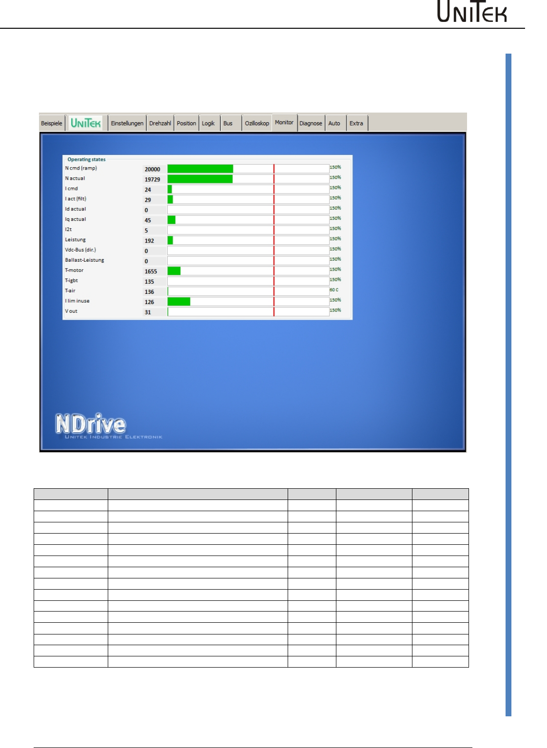
Monitor
Software – Manual N-Drive 3xx
Version 2017 / V1
88
Measured values
19 Monitor
19.1 Measured values
States
Function
Unit
Range
ID address
Ncmd Ramp
Speed command value after ramp and limit
num
0 to +/-32767
0x32
N actual
Actual speed value
num
0 to +/-32767
0x30
Icmd Ramp
Current command value after ramp and limit
num
0 to 600
0x26
Iact monitor
Actual current value (filtered)
I actual D
Actual current value D (reactive current)
num
0 to 600
0x28
I actual Q
Actual current value Q (active current)
num
0 to 600
0x27
I2t
Capacity I2xt
num
0 to 4000
0x45_L
P-Motor
Motor power
num
0 to 4000
0xf6
DC-BUS
Bus circuit voltage
num
0 to +/-32767
0xeb
P-Regen
Ballast power
num
0 to 4000
0x45_H
Tmotor
Effective motor temperature
num
0 to 32767
0x49
Tigbt
Effective output stage temperature
num
0 to 32767
0x4a
Tair
Effective air temperature in the servo
num
0 to 32767
0x4b
Ireda
Effective current limit
num
0 to 600
0x48
Vout
Output voltage
num
0 to 4000
0x8a
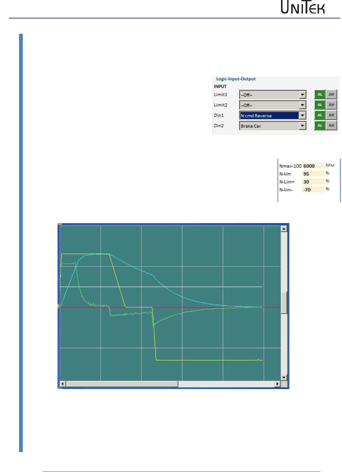
Options
89
Version 2017 / V1
Software – Manual N-Drive 3xx
Recuperation for vehicles (Brake Car)
20 Options
20.1 Recuperation for vehicles (Brake Car)
Setting BAMOCAR parameter ‘Brake Car‘ at torque control
Only positive torque command value
Activate function on the page ‘logic’
Set a digital input to ‘Brake Car’.
(Select Brake Car via the drop-down menu)
Switched on at Din2 = higher braking torque
Enter the values on the page ‘settings/parameters/speed
Input parameters : Nmax speed value for 100% speed
Input parameters : N-lim speed limiting at torque control
Braking current at torque command value 0 (minimal braking torque)
Input parameters: N-lim+ (Function changed for minimal braking torque)
Braking current at switched-on brake pressure-contact (e.g. brake light)
Input parameters: N-lim- (Function changed for increased braking torque)
Rotation direction at Brake Car
The torque command value must always be positive.
Changing the rotation direction at analog command value via Scale.
(positive value = rotating clockwise, negative value = rotating anti-clockwise).
Changing the rotation direction at digital and analog command value.
Select a digital input (e.g. Din1) on the page ‘Logik‘ as N cmd reverse.
The direction of rotation can be selected by means of the switch position.
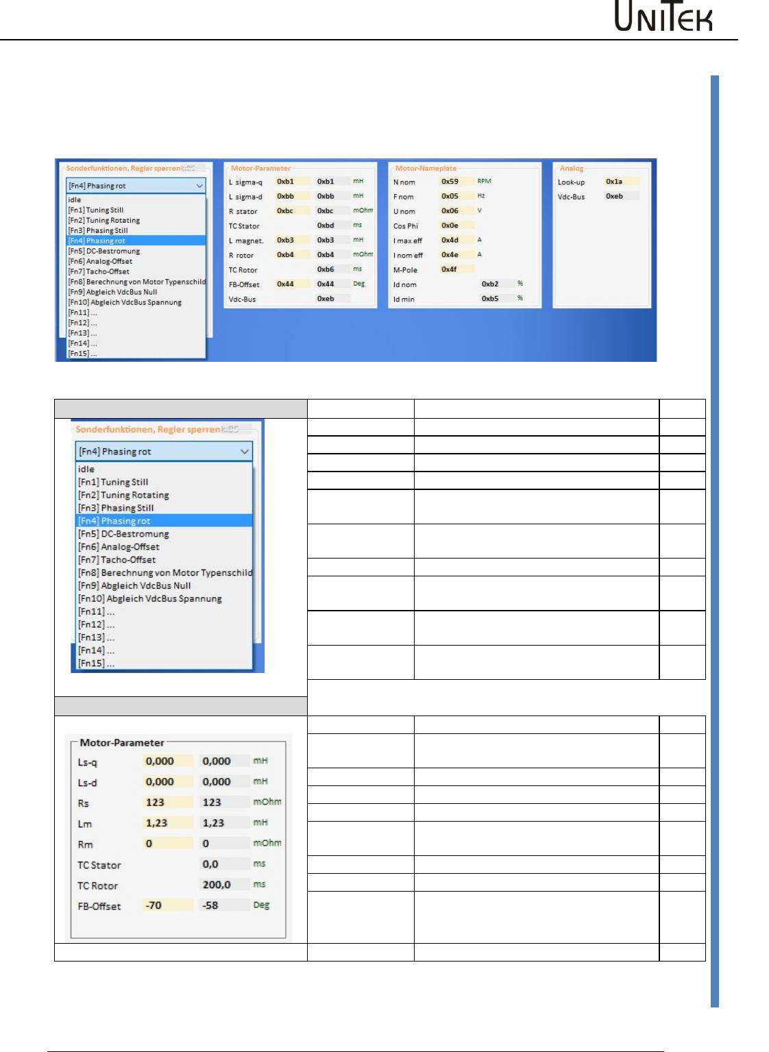
Automatic setting functions
Software – Manual N-Drive 3xx
Version 2017 / V1
90
Setting window Auto
21 Automatic setting functions
21.1 Setting window Auto
Special function
Function
Description
ID
idle
0x85
tuning still
not used
0
tuning rotating
not used
1
phasing still
not used
2
phasing red
Automatic reading of the rotor angle
(Reso-Offset)
4
DC-current
Fixed current feed angle. Set by means
of Reso-Offset
Analog-Offset
Automatic adjustment of the analog
inputs
6
Tacho-Offset
Automatic adjustment of the segment
offset at bl-Tacho
7
Calc from
motplate
Calculation of the motor data acc. to the
type plate
8
Motor parameters
Function
Description
ID
Ls-q
Stator leakage inductance in μH (without
comma), at ACIM Lsd = Lsq
0xb1
Ls-d
0xbb
Rs
Stator resistance in mΩ (without comma)
0xbc
Lm
Main inductance in 10 μH (without
comma)
0xb3
R-r
Rotor resistance in mΩ (without comma)
0xb4
TC-Stator
0xb6
TC-Rotor
Lm/Rr in ms (without comma), rotor
time constant
0xbd
FB-Offset
Encoder offset angle
0x44
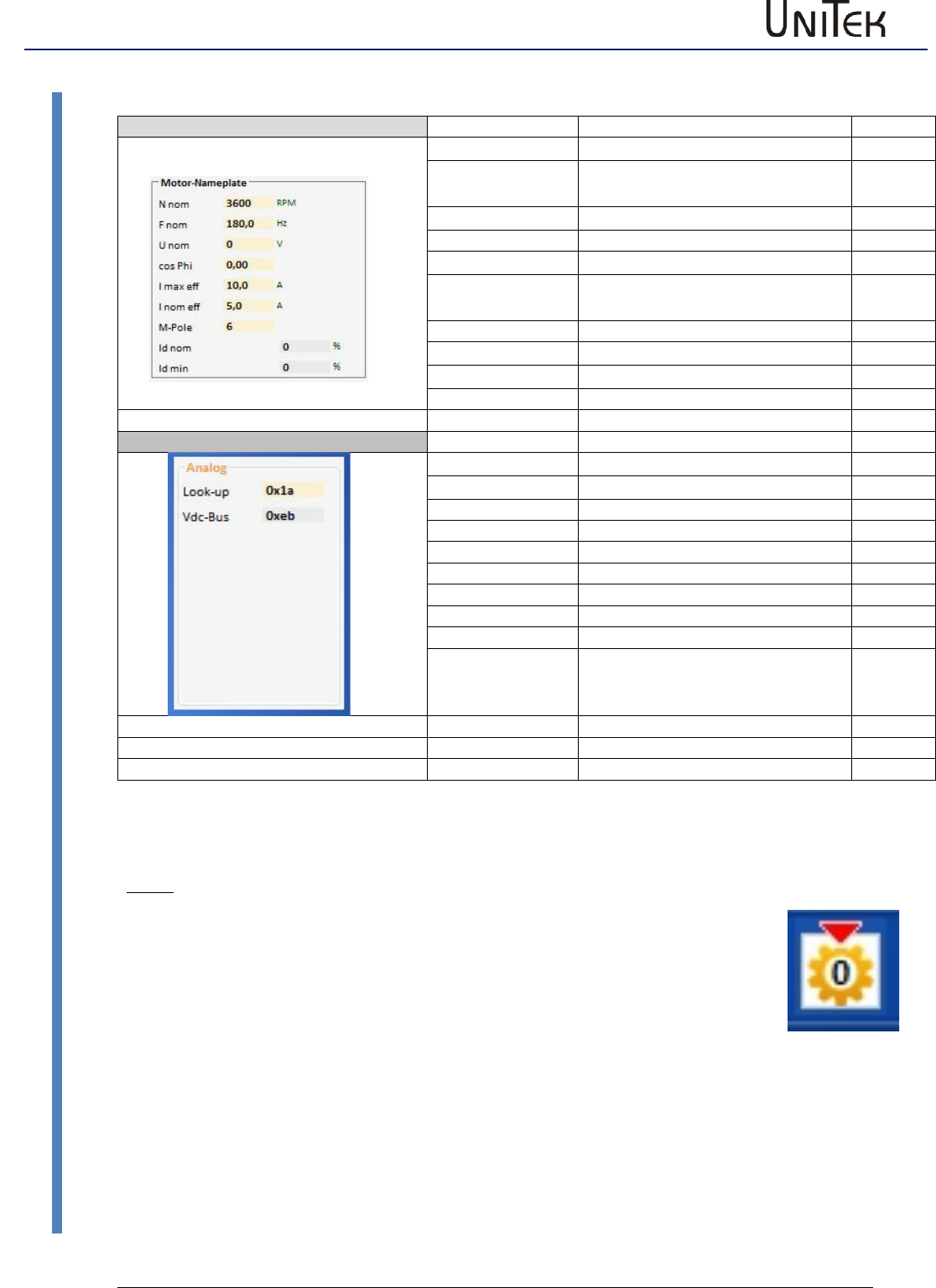
Automatic setting functions
91
Version 2017 / V1
Software – Manual N-Drive 3xx
Setting window Auto
Motor Typenschild
Function
Description
N nom
Rated speed at rated voltage
F nom
Rated frequencies at rated
voltage
U nom
nominal voltage
Cos Phi
I max eff
Motor peak current effective
I nom eff
Motor continuous current
effective
M-Pole
Motor -Pole
Id nom
reactive current
Id min
Minimum reactive current
Messwerte
Look-up
DC connection voltage in V
0x1a
Vdc-Bus
DC link voltage Num
0xeb
Note:
For the automatic adjustment Command Mode must be set of Digital Speed.
After the execution of the auto-functions the correct values must be saved on
the EEPROM level0.
Do not used functions which have not been released (currently ‘tuning still, tuning rotating,
pasing still’).
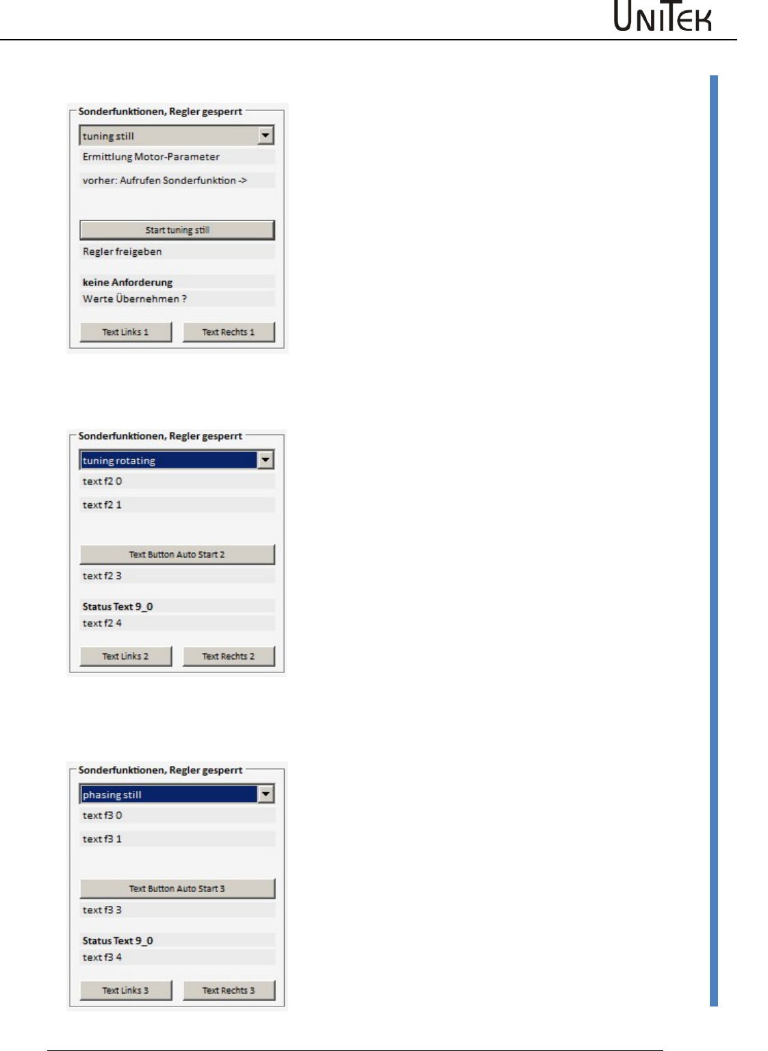
Automatic setting functions
Software – Manual N-Drive 3xx
Version 2017 / V1
92
Tuning still (0x85-1)
21.2 Tuning still (0x85-1)
Function not yet released
21.3 Tuning rotating (0x85-2)
Function not yet released
21.4 Phasing still (0x85-3)
Function not yet released
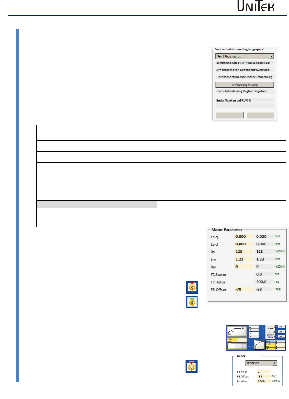
Automatic setting functions
93
Version 2017 / V1
Software – Manual N-Drive 3xx
Phasing still (0x85-3)
21.5 Measuring the encoder offset (phase angle)
Execution of phasing red (0x85 -4)
Check the no. of motor poles (MOTOR-Pole) and correct, if
necessary.
Limit the motor current:
Set the parameter Inom eff in the field ‘motor’ to max. 30 % of
the rated current value.
Set the rotation speed:
Set the parameter Speed from in the field ‘pos-reference‘
to 3 % of the rated speed.
Apply the power supply to the device, Enable open
Function
Message at NDrive
7-segment
display
Click function - request phasing
Switch on enable within 10 s
Wait for RUN= 1 (enable)
40
Enable closed
Current ramp
41
Current built up (rotation starts)
Rated value reached
42
Output rotating field
Pole angle and reading of the no. of motor poles executed
End
43
Correct end
End, wait for RUN=0 (switch off FRG)
49
Error switch-off
Enable switched off during the measuring process
Error
47
Time out , measuring time exceeded
48
During the automatic phase angle reading the states are shown in the 7-segment
display of the device (sequence: 4-0, 4-1, 4-2, 4-3, 4-9).
When the no. of motor poles and the connection are correct, the motor rotates
clockwise for one revolution (electric periode (360degree) x no. of poles/2).
If the motor rotates more than one revolution, the no. of poles is too high. If it is less
than one revolution, the no. of poles is too small.
If the motor rotates anti-clockwise check the motor connection.
At End, Wait for RUN=0 (49) the result is transmitted to the parameter FB-
Offset (0x44). Switch off enable.
After reading EEPROM level 0 the value is correctly displayed in ‘Feedback
Offset’.
Set the motor current limiting and the reference run again to the original
values.
Write the data into the EEPROM level 0!!
old value new value
Checking the encoder offset setting, fine adjustment
Operate the motor without load at approx. 50 of the rated speed.
Read the value on the page ‘speed at the parameter Vd (0x2a).
IF the value is superior to 100, adjust this value to minimum by means of slight
changes in ‘setting encoder offset (page ‘settings 0x44).
Read the changed value to the EEPROM level0.
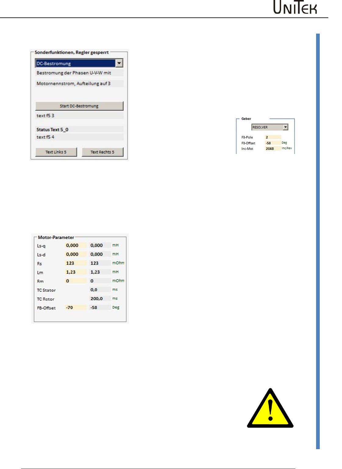
Automatic setting functions
Software – Manual N-Drive 3xx
Version 2017 / V1
94
Preset current feed angle (0x85 – 5)/fixed motor position (0x85-5)
21.6 Preset current feed angle (0x85 – 5)/fixed motor position (0x85-5)
When a current feed angle is preset (angle) the
rotor (motor shaft) is moved into this angle and
held.
Reduce the current limit for the rated current Inom
eff to 30 %.
(DC current feed is controlled to rated current, no
rotating field).
The function is started as follows:
Preset the requested angle by
means of the parameter FB-
Offset (0x44) on the page
‘settings’.
Apply the power supply to the device, enable open
Function
Description
7-segment
display
Click the function ‘start dc current
feed‘.
Switch on enable
The motor shaft rotates to the preset
angle.
As long as the enable is closed, a
new angle can be preset in the
field ‘motor parameter FB-Offset’
on the left (yellow field).
The motor shaft stops at the new angle.
----
----
When opening the enable, the function is stopped.
Note :
For further motor operation the correct value for FB-Offset must be
entered and saved (level 0).
If the FB-Offset value is incorrect, the drive may rotate or move
uncontrolled!
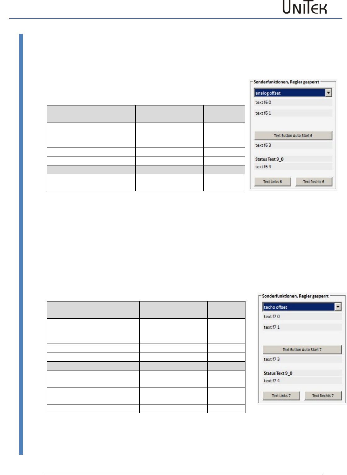
Automatic setting functions
95
Version 2017 / V1
Software – Manual N-Drive 3xx
Analog offset (0x85 -6)
21.7 Analog offset (0x85 -6)
Offset adjustment of the analog inputs.
Execute function
Apply voltages across the device, enable open
Function
Message at NDrive
7-segment
display
Click function ‘start analog
offset‘
Switch on enable
60
Correct end
69
Error switch-off
Enable switched on during
the measuring process
66
When the adjusting process is started, 6-0 is shown in the 7-segment display.
The adjusting process is finished when 6-9 is displayed.
21.8 Tacho offset (0x85 -7)
Adjustment of the segment offset error at brushless tacho systems.
Execute function
Apply voltages across the device, enable open
Function
Message at NDrive
7-segment
display
Click function ‘start analog
offset‘
Switch on enable
70
Correct end
79
Error switch-off
Enable switched on during the
measuring process
76
Movement at the rotor
detected
77
No tacho connected
78
When the adjusting process is started, 7-0 is shown in the 7-segment display.
The adjusting process is finished when 7-9 is displayed.

Automatic setting functions
Software – Manual N-Drive 3xx
Version 2017 / V1
96
Calc from Motorplate (0x85-8)
21.9 Calc from Motorplate (0x85-8)
Calculation of the motor data for asynchronous motors
Enter the motor data of the type plate or the motor data
sheet into the left column (highlighted in yellow).
After the calculation is finished the resulting values are
displayed in the right column and saved in the device.
Function
Description
ID
Ls-q
Stator leakage inductance in μH (without
comma), at ACIM Lsd = Lsq
0xb1
Ls-d
0xbb
Rs
Stator resistance in mΩ (without comma)
0xbc
Lm
Main inductance in 10μH (without comma)
0xb3
R-r
Rotor resistance in mΩ (without comma),
0xb4
TC-tator
0xb6
TC-Rotor
Lm/Rr in ms (without comma), rotor time
constant
0xbd
General information
Various literature display motor models which are identical in
principle. Abbreviations used in the diagrams may vary.
Differences can only be found concerning physically measurable
quantities (T-model) or further abstraction for simplified
calculation models (inverse gamma model).
Some manufacturers provide additional data such as no. of
poles, idle current at a specified idle voltage (= magnetization
current), ohmic resistance of the stator winding, stator
impedance at a specified frequency, as well as values referring
to rotor quantities.
These manufacturer data are usually correct and helpful. The
real, physical quantities can be measured through direct
measuring for stator values and through indirect measuring for
rotor values, i.e. by measuring the retroactive effect on the
stator.
The graphic representation of the motor models does partly not
refer to the real, physical quantity but to converted quantities.
Rs Stator resistor
ir Current in rotor
Lm Main inductance
Lrσ Rotor leakage induct.
im Magnetization current
Rr Rotor resistance
Lsσ Stator leakage induct.
iμ Current through Lm
σ Complete leakage fact.

Automatic setting functions
97
Version 2017 / V1
Software – Manual N-Drive 3xx
Calc from Motorplate (0x85-8)
Basic procedure
At operating mode FU (page setting ‘type‘) for new or unknown motors it is possible to check the
following assignment first: positive speed command value = clockwise rotating field U, V, W =
clockwise rotation = positive actual speed value. Set the values on page ‘settings’ FU left field
after U/f-characteristic. Operation in the rated point without load results approx. in the
magnetization current.
Optimization procedure
Connect a load machine with aprox. 20 to 50 % rated torque.
Setting of a corresponding torque on the scope side of the NDrive (step generator to torque,
drive enabled).
Thus, a stationary speed is adjusted.
The Lm or Rr value can be changed when the machine rotates (T-rotor = Lm/Rr).
The result is immediately effective in the control. The target is to optimize the T-rotor to a higher
speed at the same load. At operation this results in a smaller current consumption at the same
load torque.
The value of the T-rotor (in ms) is not updated by the NDrive until the offline-online process.
At a second stage Idnom (NDrive page ‘speed‘) can be varied, field weakening not active (Vred =
0). This can be noticed during standstill (current = magnetization current). When the machine
rotates thisvalue is also immediately effective. The target is again a higher speed at the same
load. At operation this results in a higher final speed when reaching the voltage limit (max.
modulation).
Compare the values achieved from the tests with existing manufacturer values. Save them and
reset the drive (off-on) . Check the values and functions again.
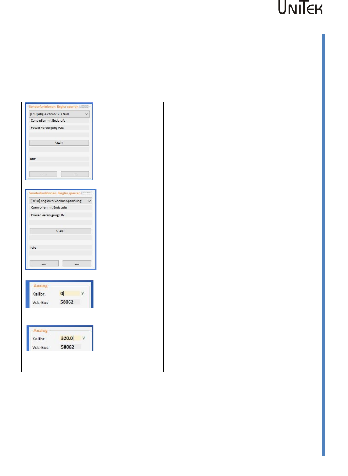
Automatic setting functions
Software – Manual N-Drive 3xx
Version 2017 / V1
98
Calc from Motorplate (0x85-8)
21.10 VdcBus Adjustment
From firmware FW466 onwards
The calibration is made in the factory.
In case a component is exchanged it is necessary to re-adjust again.
Adjustment of measuring errors errors oft he bus circuit voltage measurement.
Zero point adjustment
No power supply voltage!
Bus circuit 0 V (to be short-circuit.)
Start adjustment via key „START“.
After approx. 4 seconds the value for
VdcBus=0 is calculated.
Slope error adjustment
After the 0 adjustment it is necessary to adjust
the slope error.
With bus circuit voltage without ripple:
Measure the bus circuit voltage by means of a
voltmeter and register the value in Kalibr.
Start the adjustment.
After approx. 4 sec. the measurement value
for VdcBus is displayed (Num).
In case there is no exact bus circuit voltage
available:
Adjustment without power supply voltage:
Bus circuit voltage = 0 V
Enter 0 V in the field „calibration“ and start
the adjustment.
Save the determined measured values
permanently by means of the EPROM-STORE.
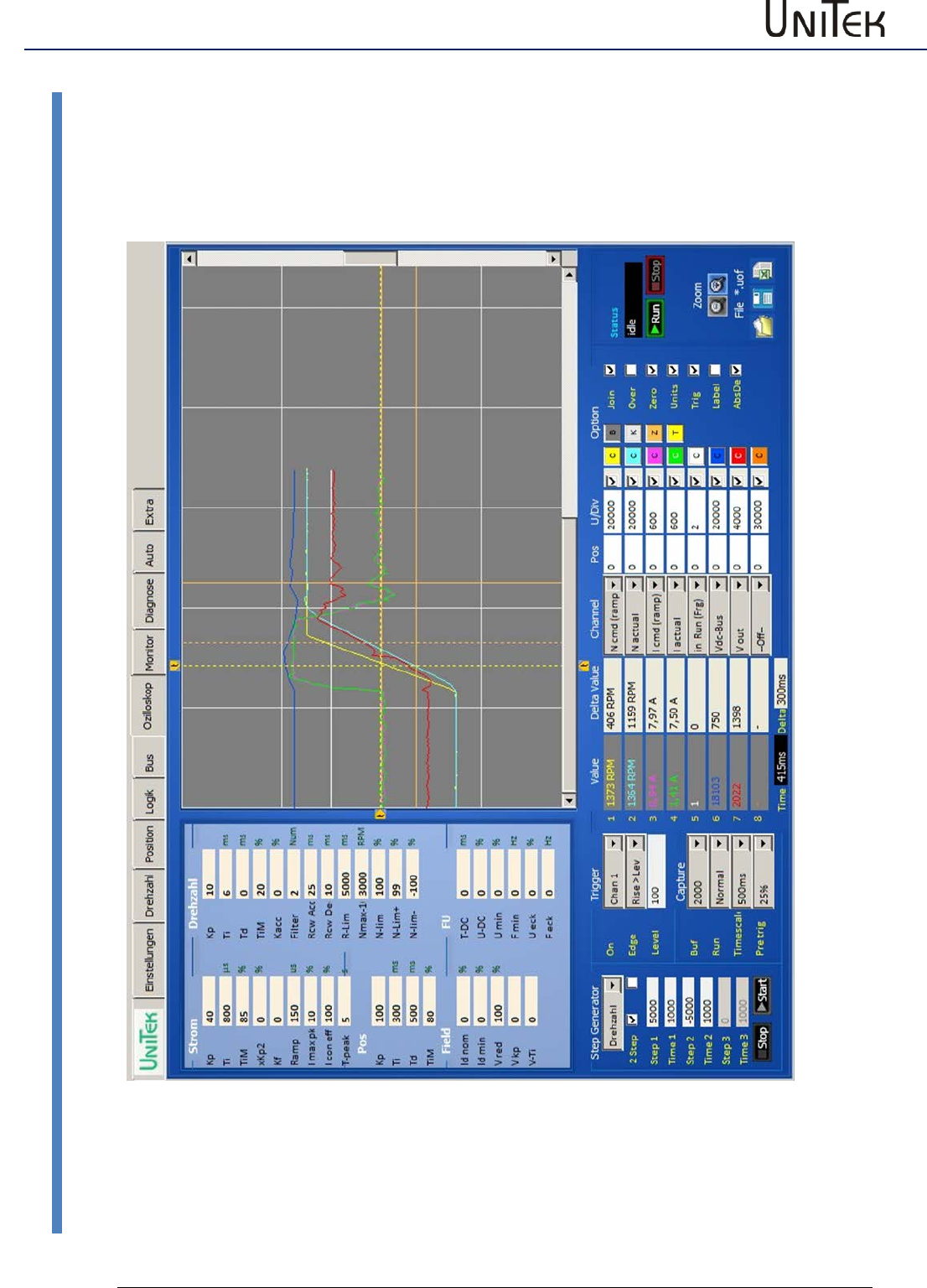
Oscilloscope
99
Version 2017 / V1
Software – Manual N-Drive 3xx
Overview
22 Oscilloscope
22.1 Overview
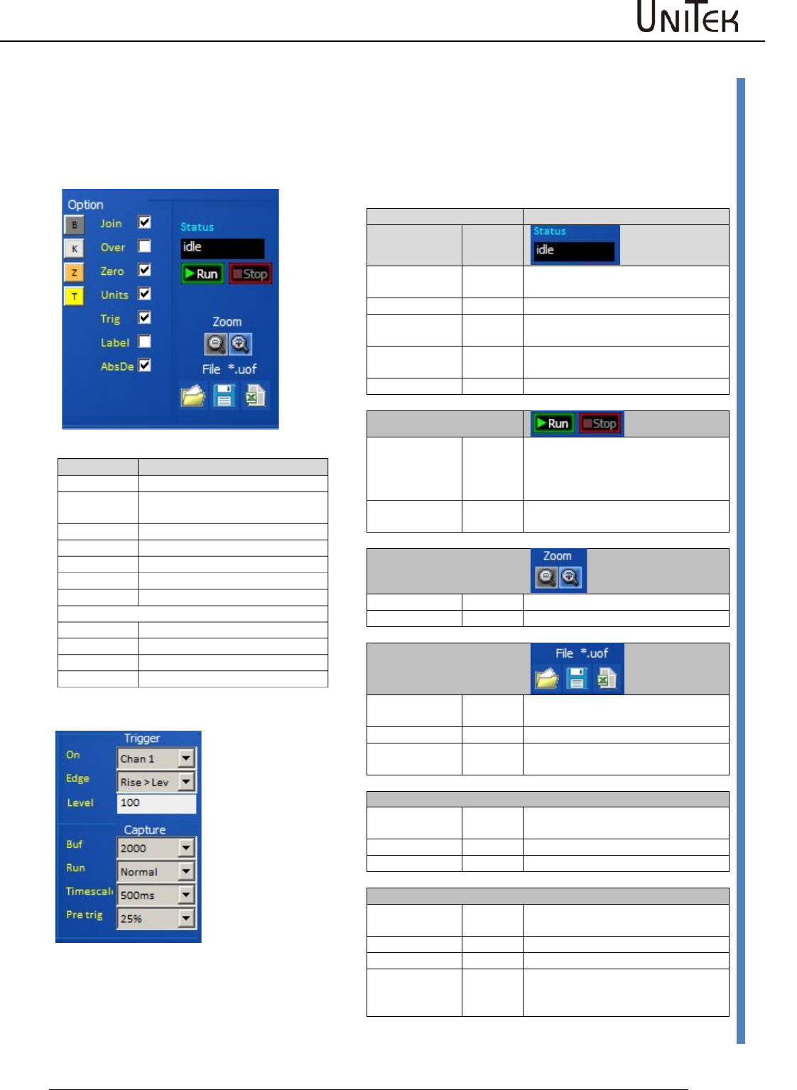
Oscilloscope
Software – Manual N-Drive 3xx
Version 2017 / V1
100
Oscilloscope settings
22.2 Oscilloscope settings
Screen functions
Trigger settings
Function
State
Colour
waiting (0)
red
Display of the last recording and
waiting for a new triggering
waiting (xx)
green
triggered, data are saved
reading
blue
Reading of the data from the drive
to the pc
drawing
Display of the data on the
oscilloscope screen
idle
white
Frozen data after ‘Stop capture‘
Run Stop
Run
The oscilloscope recording is
focused via the key field ‘run
capture’. The recording is started at
the next triggering signal.
Stop
The recording is cancelled via ‘stop
capture‘ and the display is frozen.
Zoom
Zoom +
The screen content is enlarged
Zoom -
The screen content is reduced
File
File left
Load the oscilloscope file from the
pc
File middle
Save the oscilloscope file into the pc
File right
Save the oscilloscope file as excel
file
Trigger
On
Selection of the channel for the
trigger function
Edge
Selection of the trigger function
Level
Trigger level (numerical)
Capture
Buf
Resolution, horizontal pixels for all
switched-on channels
Run
Selection trigger switching function
Timescale
Time unit per horizontal grid line
Pre trig
Horizontal shifting of the trigger
line. Measured value display before
the trigger line.
Option
Time basis (per grid)
Join
Pixels connected
Over
The display remains and is over-
written
Zero
Zero line visible
Units
Display as num or real values
Trig
Trigger line visible
Label
Channel designation visible
AbsDe
Screen colours
B
Oscilloscope background
K
Oscilloscope grid
Z
Oscilloscope zero line
T
Oscilloscope trigger line
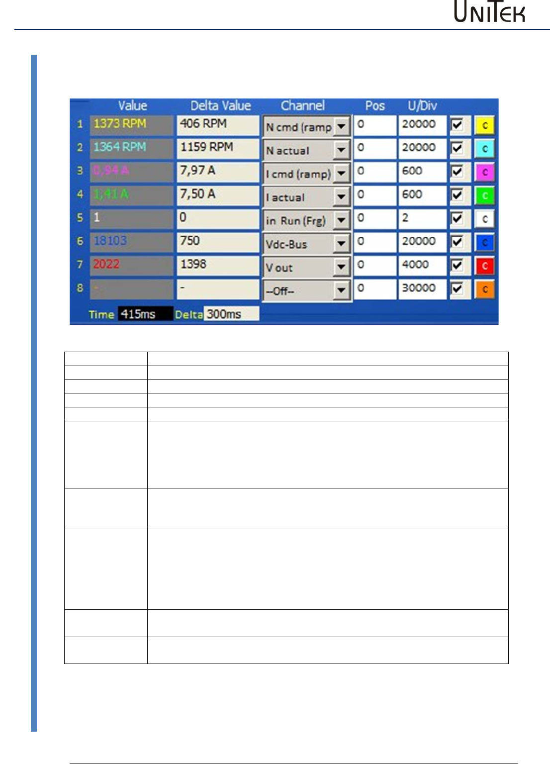
Oscilloscope
101
Version 2017 / V1
Software – Manual N-Drive 3xx
Arrow key for the channel selection
22.3 Arrow key for the channel selection
Field
Function
Value
Value at the first cursor line (numerical or real)
Time
Time from the trigger line to the first cursor line
Delta Value
Difference values from the first to the second cursor
Delta (Time)
Difference time from the first to the second cursor
Channel:
All measured values from the selection table can be displayed on the
oscilloscope. The drop-down menu opens by clicking the arrow key. The
required measured value is selected and assigned to the channel no.
The channel is switched off at ‘off‘.
Channels which are not required must always be switched off! (Off)
Pos:
The value of 100 corresponds to a horizontal grid line.
E.g.: At value 50 the zero line of the selected channel is shifted upwards by
half a square.
U/Div:
Units for a horizontal grid line.
E.g.: U/Div = 32768 at N cmd Ramp. (N max parameter = 3000 rpm)
The numerical value (32768) of the speed command value corresponds to a
horizontal line at 3000 rpm.
At cursor request a horizontal line equals 100.
Thus, the cursor value 100 corresponds to a speed of 3000.
Switch cabinet
The display of the channel is switched on and off.
The switched-off channel remains in the background and is also saved.
Channel colours
A colour selection window is opened by clicking the colour key C.
Select the new channel colour and accept it by clicking ‘ok’.
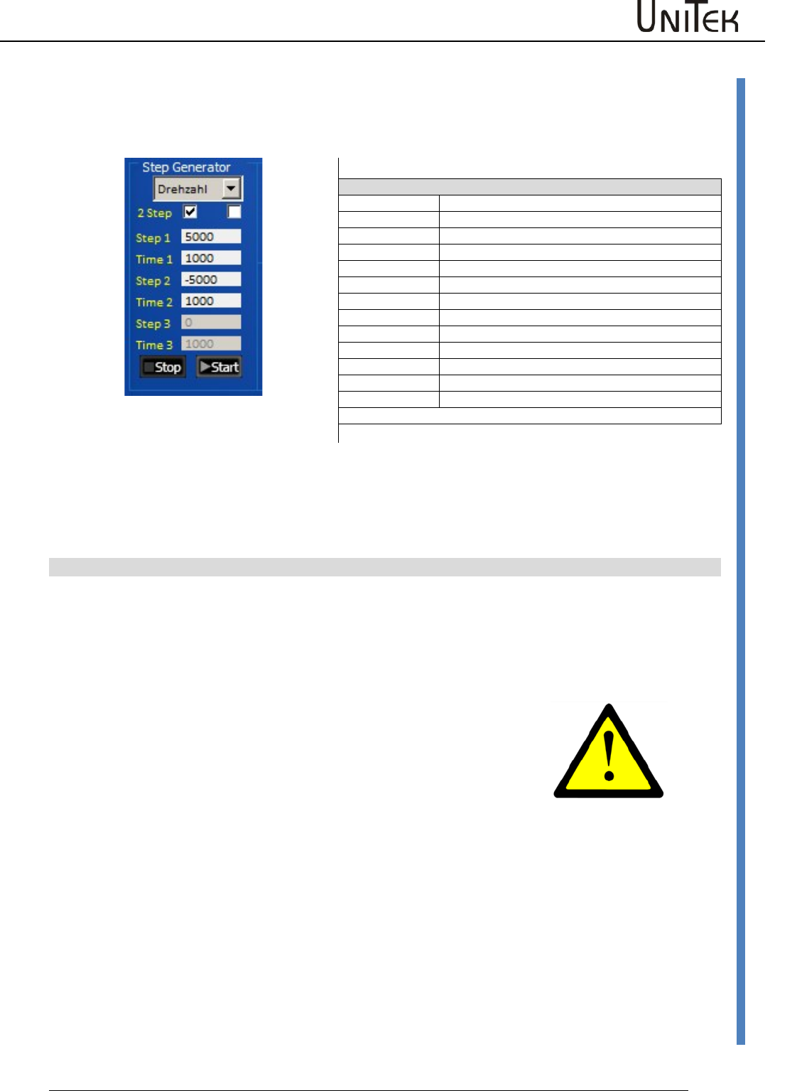
Oscilloscope
Software – Manual N-Drive 3xx
Version 2017 / V1
102
Trigger settings
22.4 Trigger settings
Test generator for the selection of command values in rectangle functions
NDrive-Oszi-Step-Drehzahl-1
Selection
Current
Generator function is the current command value
Torque
Generator function is the torque command value
Speed
Generator function is the speed command value
Position
Generator function is the position command value
2Step
Selection 2 or 3 Step
Functions
Step1
Value1 for current, speed, or distance
Time1
Time for value 1
Step2
Value 2 for current, speed, or distance
Time2
Time for value 2
Stop 3
Standstill value for current, speed, or distance
Time 3
Stopp time
Start Stop
Starts or stops the generator function
Note: The time inputs (time) may vary acc. to the pc for values >2000.
Command value step functions are preset by means of the test generator. The ramps are determined
via the parameter settings for the current and speed controller. When the controller enable (RUN/Frg)
is active, the drive is started by clicking the field ‘start’ and it is stopped by clicking ‘stop’. The functions
can be selected as current, torque, speed, or position values. The value for ‘stop’ at current, torque,
and speed should be 0 for standstill. ‘Stop‘ can also be used like ‘step(1,2)‘.
Note: Maximal values for step1, step2, and stop
At current
+/- 330
At torque
+/- 32767
At speed
+/- 32767
At position
+/- 2147483647
At time
32767
Particular attention
If the travel distance is limited it has to be ensured that the travel
distance of the test settings is within the machine limits.
At the test setting ‘current’ and ‘torque’ the drive may rotate at
max. speed.
Over-speed may be achieved at field weakening.
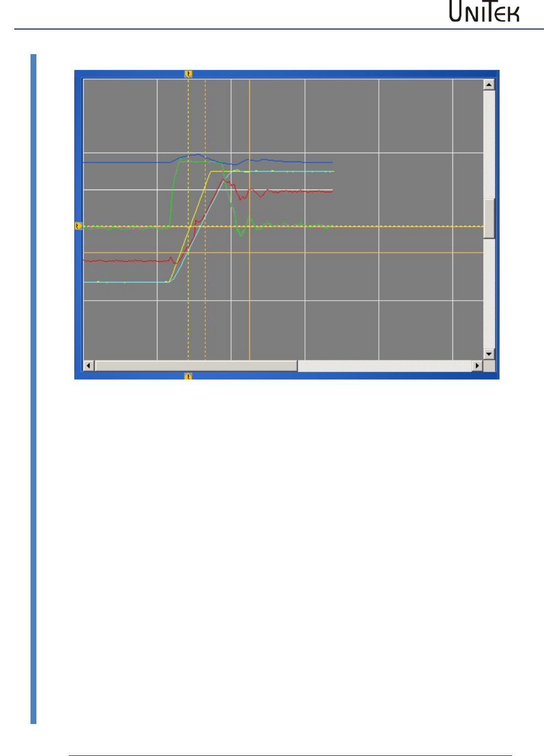
Oscilloscope
103
Version 2017 / V1
Software – Manual N-Drive 3xx
Display of measured values
22.5 Display of measured values
The recording of the measured values is displayed with the selected colours.
The first vertical trigger line is tagged with an arrow symbol at the upper and lower edge of the
screen.
The second vertical line is the first cursor line.
The active second cursor is displayed as horizontal and vertical crossline.
The measured values at the first vertical cursor line are displayed at value and saved.
The measured value at the second cursor (crossline) are displayed in the fields delta value as
difference values to the values at the first cursor.
The time from trigger line to the first cursor line is displayed at time.
The time between the first cursor line and the second cursor line is displayed at delta time.
If the box units is ticked the displayed values are transformed from numerical to real values.
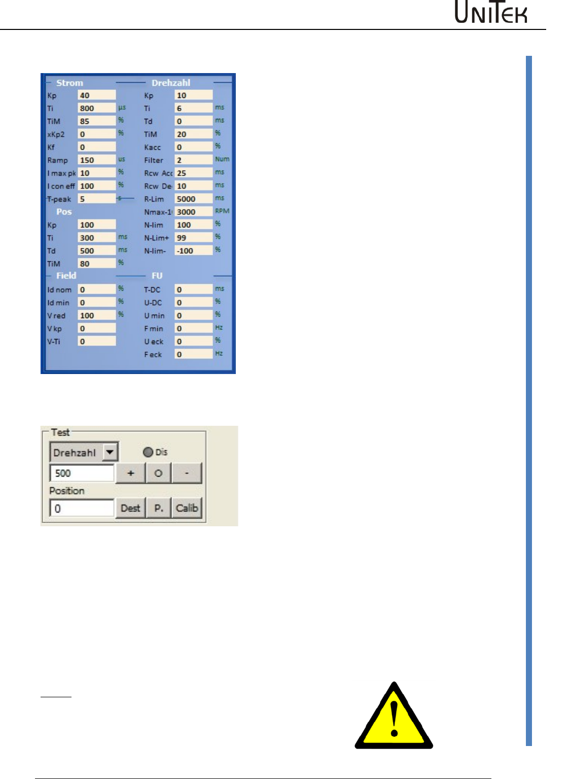
Oscilloscope
Software – Manual N-Drive 3xx
Version 2017 / V1
104
Parameters on the oscilloscope page
22.6 Parameters on the oscilloscope page
The parameters of the page ‘oscilloscope‘ can be
changed during the test function.
The modifications are transferred to the current
parameter set.
The result is immediately displayed on the
oscillioscope screen after the next triggering.
22.7 Test operation
Test
Setting : Command mode = digital speed
Direct input and execution of speed or torque.
Selection via the drop-down menu.
Dis : Software enable
(only if hardware enable is active)
Position in numerical values.
Speed or torque
Enter the speed value. The entered speed is immediately processed when the key + or - is clicked.
The command value is internally set to zero when the ‘stop’ key is clicked.
Position
Enter the position value. When clicking the key ‘dest.‘ the drive travels immediately at the speed
selected at Nmax(Nlim) to the entered position. When clicking the key ‘calib.‘ the drive travels a
reference cycle.
The entered position is imported as actual position and command value position via the key P.
Note :
Only for test function. The functions are directly executed!
Parameters
105
Version 2017 / V1
Software – Manual N-Drive 3xx
Parameter tables
23 Parameters
23.1 Parameter tables
Motor value settings
Short symbol
Function
Setting range
Units
Note
REGID address
Type
see type
N nom
Rated motor speed
Type plate
rpm
0x59
F nom
Rated frequency
Type plate
0.1 Hz
0x05
U nom
Rated voltage
Type plate
1 V
0x06
U phi
Cosinus Phi
Type plate
Dec
0x0e
I max
Max. motor current
Type plate
0.1 A
0x4d
I nom
Continuous motor current
Type plate
0.1 A
0x4e
M-Pole
No. of motor poles
2..48
num
0x4f
Direction
Global rotation direction
Switch
0x5a.8
Brake
Brake with/without
Switch
0x5a.9
Brake Delay
Brake delay
0 to 1000
ms
0xf1
coast stop
Coasting when not enabled
0x5a.3
Feedback
see motor options
Selection
0x4a.--
F- Pole
No. of feedback encoder poles
2..12
num
0xa7
Offset
Phase angle feedback
0 .. 360
0.1 degree
0x44
Inc-Mot
Incremental encoder resolution
1024..8192
pulses/rpm
0xa6
2.Feedback
see motor options
Selection
0x4a.--
Inc-Out
see motor options
Selection
0x4a.--
Motor Type
Short symbol
Function
Address
Motor type
REGID 0xa4
EC (sinusoidal)
Synchronous servo motor sinusoidal voltage
0
Bit 8..10
AC (induction)
Asynchronous motor
1
DC
DC motor
2
EC (trapezoidal)
Synchronous servo motor trapezoidal voltage
3
Motor - Optionen
Short symbol
Function
Address
Feedback
REGID 0xa4
ROTENC_TTL
Incremental encoder TTL 5 V with rotor position tracks
0
Bit 0…4
RESOLVER
Resolver
1
ABSENC_SC
Incremental encoder Sin/Cos 1Vss with commutation track
2
ROT_TACHO
Rotor position encoder with brushless tacho
3
ROT
Rotor position encoder (without tacho)
4
DC_TACHO
DC tacho generator
5
DC_ARM
Armature voltage (internal)
6
BL_ARM
EC-AC-motor without tacho
7
ENC_TTL
Incremental encoder TTL 5 V without rotor position
8
ENC_SC
Incremental encoder Sin/Cos 1Vss without commutation track
9
ABS_SC
Incremental encoder Sin/Cos 1Vss per motor pole pair
10
DC_ARM_VIR
Without sensor (DC motor without tacho, without armature
voltage measuring)
11
SLS
Without sensor
12
SLS_SMO
not activated
13
SLS_Usens
not activated
14
Analn1-calc
not activated
15
Analn2-calc
not activated
16
PANA
Serial encoder system
17
.
.
Parameters
Software – Manual N-Drive 3xx
Version 2017 / V1
106
Parameter tables
2. Feedback
Function
Address
Off
0
Bit 5..7
INC-IN
X8 as position input
1
INC-OUT
X8 display only
2
HAND
X8 as handwheel input
3
Inc-Out
Factor
Output factor with SINCOS
Inc-Out
Output with resolver
Servo settings
Short symbol
Function
Setting range
Units
Note
REGID address
Type
Display of the unit type
0x67
SNr.
Display of the serial no.
Type plate
0x62
Achse
Axis designation
Customer
0xf8
Mains sel
Voltage selection dc/ac
Switch
0x5a-19
Mains
Power voltage supply
Type plate
1 V
0x64
DC-BUS max
max. bus circuit voltage
1 %
0xa5H
DC-BUS min
min. bus circuit voltage
1 %
0xa5L
ZW-Monitor
Bus circuit measurement dig./anal.
Switch
0x5a-7
Regen
Internal/external ballast resistance
Switch
0x5a-1
Regen-P
Ballast resistance power
1 W
0x65L
Regen-R
Ballast resistance value( Ohm)
1 Ω
0x65H
BTB Power
BTB message
with/without power voltage
Switch
0x5a-6
Takfreq.
see clock frequency
Selection
Analog Out
Selection drop-down list
Selection
Clock frequency settings
Short symbol
Function
Address REGID
Clock frequency
0x5a
8kHz
0
Bit 20...22
24kHz
1
20kHz
2
16kHz
3
12kHz
4
8kHz I16
internal 16 kHz
5
4kHz I8
internal 8 kHz
6
2kHz I4
internal 4 kHz
7
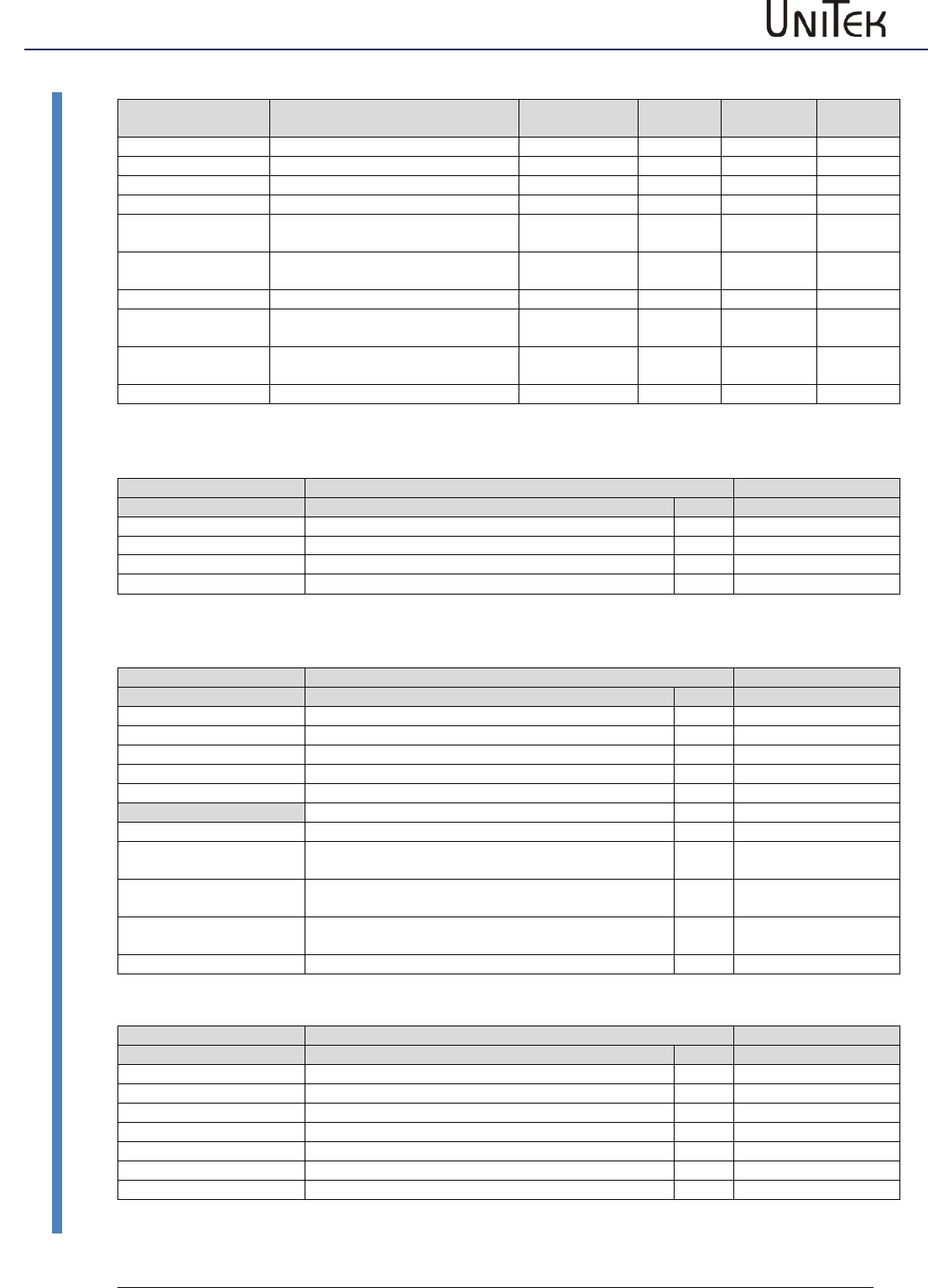
Parameters
107
Version 2017 / V1
Software – Manual N-Drive 3xx
Parameter tables
Command (command values)
Short symbol
Function
Setting range
Units
Note
REGID
address
Mode
see command mode
Selection
Cutoff-digital-cmd
Zero-zone digital command value
+/-32767
Num
0x1e
Format Ain1, Ain2
see command format
Selection
Offset Ain1
Command value offset analog input 1
+/-32767
Num
0x2fL
Cutoff Ain1
Zero-zone command value
analog input 1
+/-32767
Num
0x50
Scale Ain1
Scaling command value
analog input 1
+/-32767
Num
0x2fH
Offset Ain2
Command value offset analog input 2
+/-32767
Num
0x2fL
Cutoff Ain2
Zero-zone command value
analog input 2
+/-32767
Num
0x50
Scale Ain2
Scaling command value
analog input 2
+/-32767
Num
0x2fH
Mode Ain1, Ain2
see Ain1, Ain2 mode
Selection
Command mode
Short symbol
Function
Address
Command mode
REGID 0x36
Digital Speed
Digital speed command value of RS232 or BUS
0
Bit 12...13
Analog Speed
Analog speed command value
1
Analog Torque
Analog torque command value
2
Digi + Ana Speed
Digital plus analog command value
3
Command format
Short symbol
Function
Address
Command format Ain 1
REGID 0x36
Off
Open, not used
0
Bit 0...1
Cmd
Analog command value 1
1
-Cmd
Analog command value 1 negated
2
sq(cmd)
Analog command value 1 quadratic
3
N-Limit
Analog input 1 as speed limit
Bit 15
Command format Ain2
Bit 2...3
Off
Open, not used
0
+Cmd
Analog command value 2 added to the analog command
value 1
1
-Cmd
Analog command value 2 subtracted from the analog
command value 1
2
* Cmd
Analog command value 2 multiplied by the analog
command value 1
3
I-Limit
Analog input 2 as current limit
Bit 14
Command mode range
Short symbol
Function
Address
Mode range Ain1
REGID 0x36
-10...+10V
Command value plus-minus max. 10 V
0
Bit 4...5
0...+10V
Command value plus max. 10 V
1
4...20mA (+2V...+10V)
Command value 4 to 20 mA at 500 Ohm
2
Mode Range Ain2
Bit 8..9
-10...+10V
Command value plus-minus max. 10 V
0
0...+10V
Command value plus max. 10 V
1
4...20mA (+2V...+10V)
Command value 4 to 20 mA at 500 Ω
2
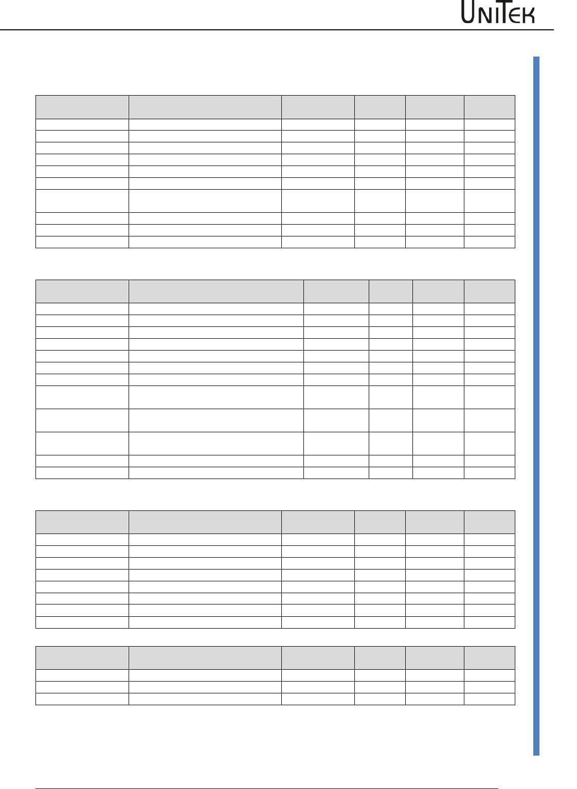
Parameters
Software – Manual N-Drive 3xx
Version 2017 / V1
108
Parameter tables
Current controller parameter
Command values, actual values, control errors (current)
Short symbol
Function
Setting range
Units
Note
REGID
address
I man
Manual current command value
+/- 2048
Num
0x21
I cmd
Current command value
+/-2048
Num
0x26
I cmd ramp
Current command value after ramp
+/-2048
Num
0x22
Iq actual
Actual active current value
+/-2048
Num
0x20
Id actual
Actual reactive current value
+/-2048
Num
0x28
I act
Total current - actual value
+/-2048
Num
0x20
I act monitor
Total current - actual value
after display filter
+/-2048
Num
0x5f
Iq error
Active current control fault
+/-2048
Num
0x38
Id error
Reactive current control fault
+/-2048
Num
0x39
Id ref
Reference value
+/-2048
Num
0x23
Current limits, ramps
Short symbol
Function
Setting range
Units
Note
REGID
address
+I max
Current limit peak current positive
0...100
%
0xc4
+I con
Current limit continuous current positive
0...100
%
0xc5
-I max
Current limit peak current negative
0...100
%
-I con
Current limit continuous current negative
0...100
%
Tpeak
Tiem peak current
0...30000
ms
0xf0
I-lim-dig
Current limit switched via input
0..100
%
0x46
I-red-N
Current limit controlled via speed
0...100
%
0x3c
I-red-TD
Current limit controlled via output stage
temperature
0..32767
Num
0x58
I-red TE
Current limit controlled via rms current
(I2t)
0..32767
Num
0x4c
I-red-TM
Current limit controlled via motor
temperature
0..32767
Num
0xa2
I2t actual
Display rms current + time
0..32767
Num
0x25
I-lim actual
Display resulting current limit
0..32767
Num
0x48
Output stage voltages
Short symbol
Function
Setting range
Units
Note
REGID
address
Vq
Internal calculated value FOC
0x29
Vd
Internal calculated value FOC
0x2a
Vout
Output voltage
0 to 4096
0x8a
Vred
Starting point field weakening
0x8b
Vkp
P amplification field weakening
0x8c
VTi
I time field weakening
0x8d
DC-Bus
Bus circuit voltage
0 to 32767
0xeb
Control parameters of the current controller
Short symbol
Function
Setting range
Units
Note
REGID
address
KP
Proportional amplification
0 to 200
num
1=0.1
0x1c
Ti
Integration time
300 to 2000
ms
150
0x1d
TiM
Max. integration time memory
0 to 100
%
1
0x2b
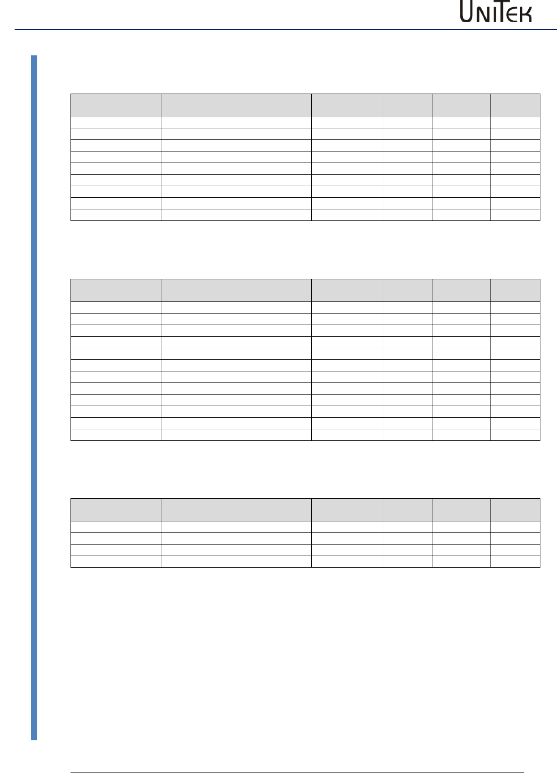
Parameters
109
Version 2017 / V1
Software – Manual N-Drive 3xx
Parameter tables
Speed controller parameters
Command value, actual value, speed, torque
Short symbol
Function
Setting range
Units
Note
REGID
address
Analog int Ain1
Analog input 1 internally processed
0xd5H
Analog int Ain2
Analog input 1 internally processed
0xd6H
Dig-Speed
Digital speed command value
0x31
Dig-Torque
Digital torque command value
0x90
N cmd
Speed command value
+/-32767
num
0x5d
N cmd Ramp
Speed command value after ramp
+/-32767
num
0x32
N actual
Actual speed value
+/-32767
num
0x30
N act monitor
Actual speed value after display filter
+/-32767
num
0xa8
N error
Speed control fault
+/-32767
num
0x33
Limits, ramps, speed, torque
Short symbol
Function
Setting range
Units
Note
REGID
address
Ramp-sel
see selection ramp sel
Selection
RCW-Acc
Acceleration positive speed
0...30000
ms
0x35L
RCW-Dec
Deceleration positive speed
0...30000
ms
0xedL
RCCW-Acc
Acceleration negative speed
0...30000
ms
0x35H
RCCW-Dec
Deceleration negative speed
0...30000
ms
0xedH
S-Form
see selection ramp form
Selection
RCW-Lim
Delay emergency stop
0...30000
ms
0xc7
Nmax 100%
max. speed for 100%
600 to 50000
rpm
0xc8
N-Lim
Speed limiting
0...100
%
0x34
N-Lim+
Positive speed limiting
0...100
%
0x3f
N-Lim-
Negative speed limiting
0...100
%
0x3e
Filter
Speed actual value filter
0..7
num
0x5e
Control parameters of the speed controller
Short symbol
Function
Setting range
Units
Note
REGID
address
KP
Proportional amplification
0 to 200
Num
1=0.1
0x2c
Ti
Integration time
5 to 100
ms
0.75
0x2d
Td
Rate time
1 to 10000
ms
0.75
0x2e
TiM
Max. integration time memory
0 to 100
%
1
0x3b
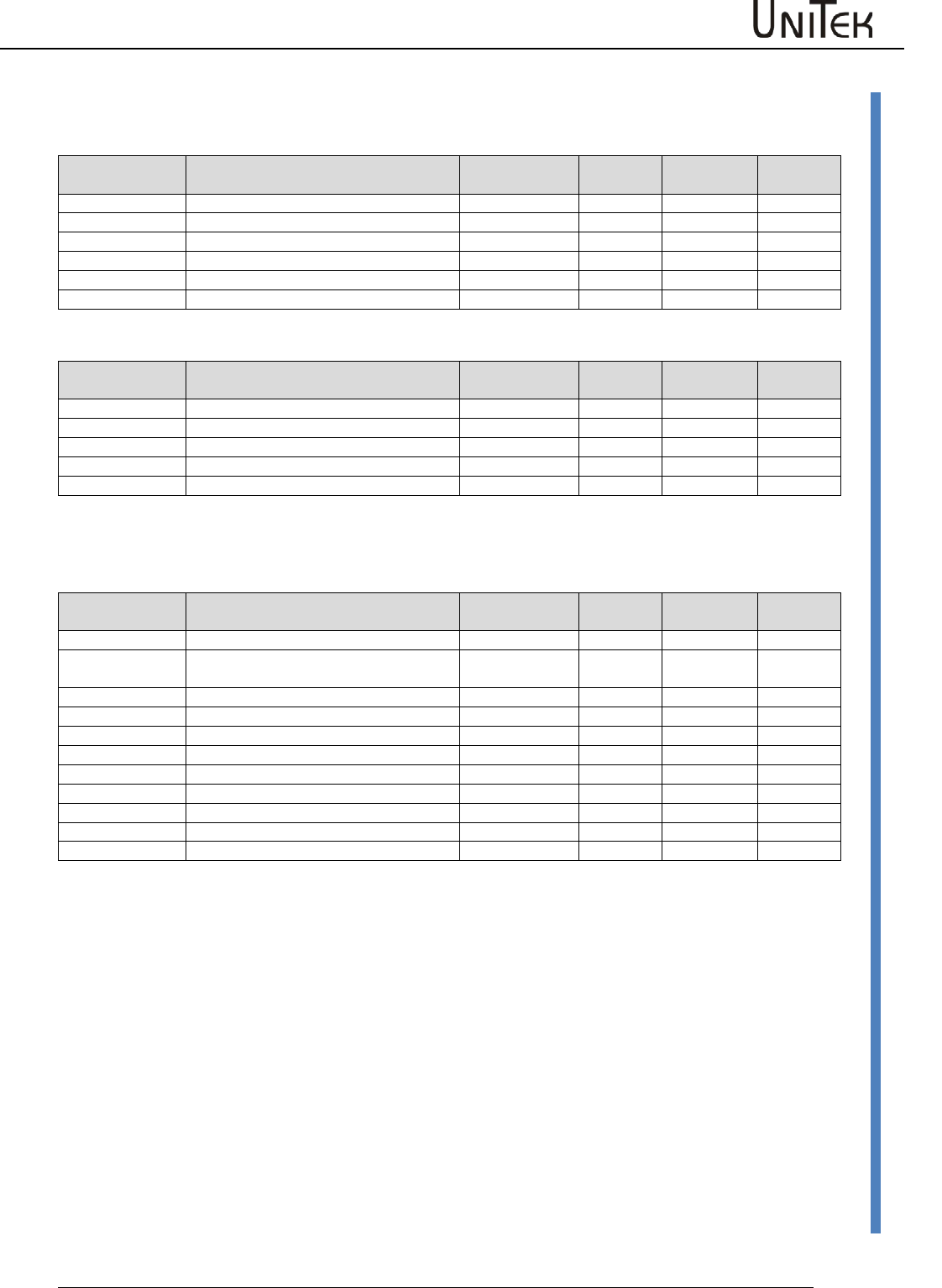
Parameters
Software – Manual N-Drive 3xx
Version 2017 / V1
110
Parameter tables
Position controller parameters
Reference run
Short symbol
Function
Setting range
Units
Note
REGID
address
Speed to
Speed to the reference position
10 to 32000
num
1
0x76
Speed from
Loop speed
10 to 2000
num
1
0x77
Reso Ed
0x75
Dec-Ramp
Acc Ramp or Limit Ramp
Switch
Position controller Pos->Speed
Short symbol
Function
Setting range
Units
Note
REGID
address
KP
Proportional amplification
0 to 200
num
1=0.1
KP
Z-Faktor
Z-Faktor
Ti
Integration time
10 to 500
ms
0.75
Ti
Td
Rate time
500 to 10000
ms
0.75
Td
TiM
Max. integration time memory
0 to 100
%
1
TiM
Position controller parameters
Short symbol
Function
Setting range
Units
Note
REGID
address
Tol-wind
Proportional amplification
0 to 100
num
1=0.1
0xc9
Ref- Off
Zero offset
0 +/-
2147483647
num
1
0x72
ND-Scale
Display - factor
num
1
0xcb
ND-Offset
Display - offset
num
1
0xcd
Pos dest
Position target
0x6e
Pos cmd
Position command value
0x91
Pos actual
Actual position value
0x6d
Pos error
Position control fault
0x70
Inc-Out
Increment output
Inc-ext
Increment 2. feedback
Faktor-ext
Factor 2. feedback
0x7e
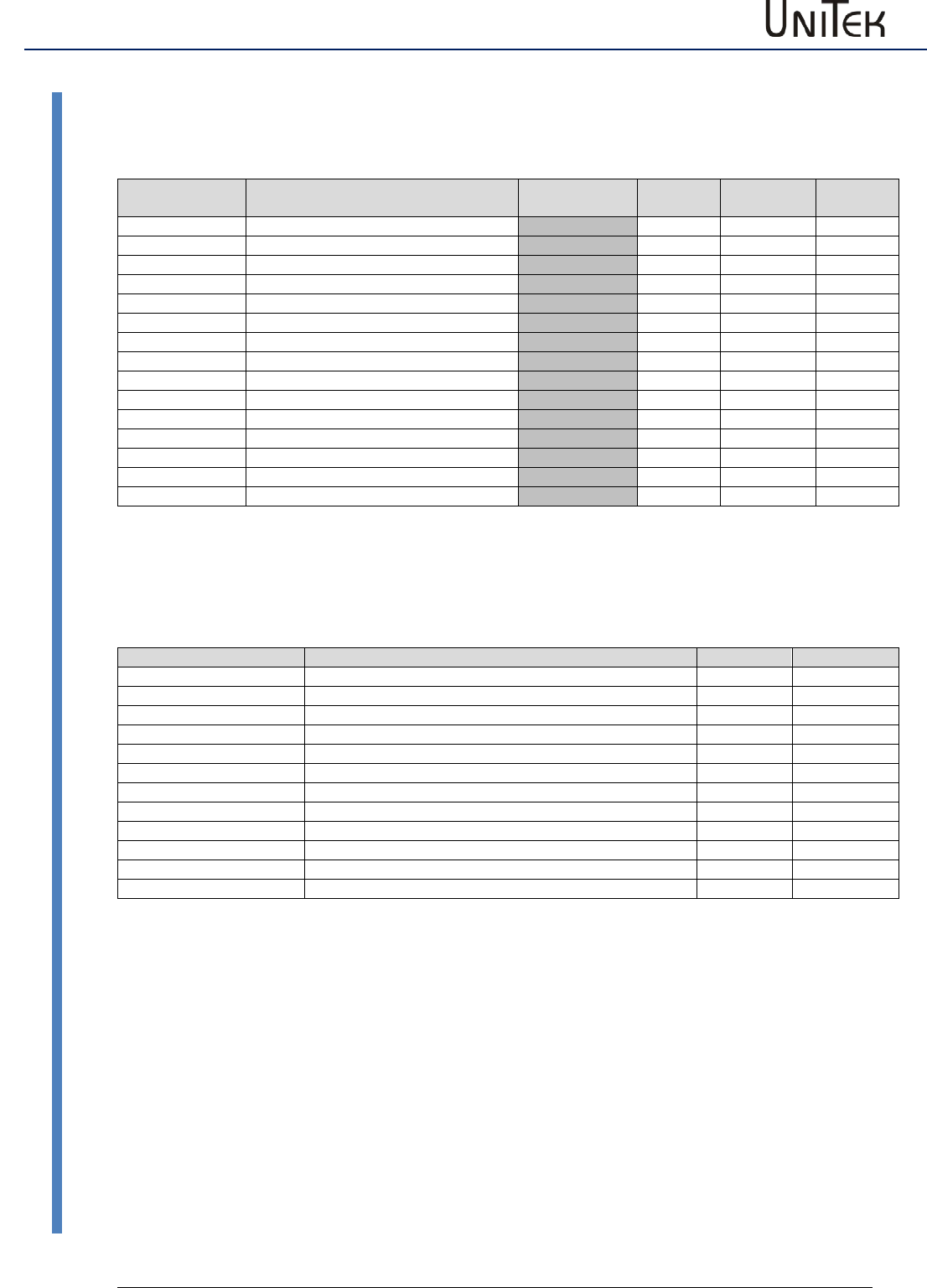
Parameters
111
Version 2017 / V1
Software – Manual N-Drive 3xx
Parameter tables
Frequency converter parameters
Frequency converter (FU) settings
Short symbol
Function
Setting range
Units
Note
REGID
address
Start
T-DC
dc magnetization time
ms
0x07L
I-DC
dc magnetization
1 %
0x08L
Umin
min. voltage
0.1 %
0x0aL
F min
min. frequency
0.1 Hz
0x0bL
U eck
Voltage at rated speed
0.1 %
0x0cL
F eck
Frequency at rated voltage
0.1 Hz
0x0dL
Stop
T-DC
dc magnetization time
ms
0x07H
I-DC
dc magnetization
1 %
0x08H
Umin
min. voltage
0.1 %
0x0aH
F min
min. frequency
0.1 Hz
0x0bH
U eck
Voltage at rated speed
0.1 %
0x0cH
F eck
Frequency at rated voltage
0.1 Hz
0x0dH
F-sh
see F-shape
F-shape frequency converter settings
Short symbol
Function
Address
REGID 0x0f
F-sh Start
Bit 1..2
linear
presently only linear
0
quad/2
1
quad
2
opt
3
F-sh Stop
presently only linear
linear
quad/2
quad
opt
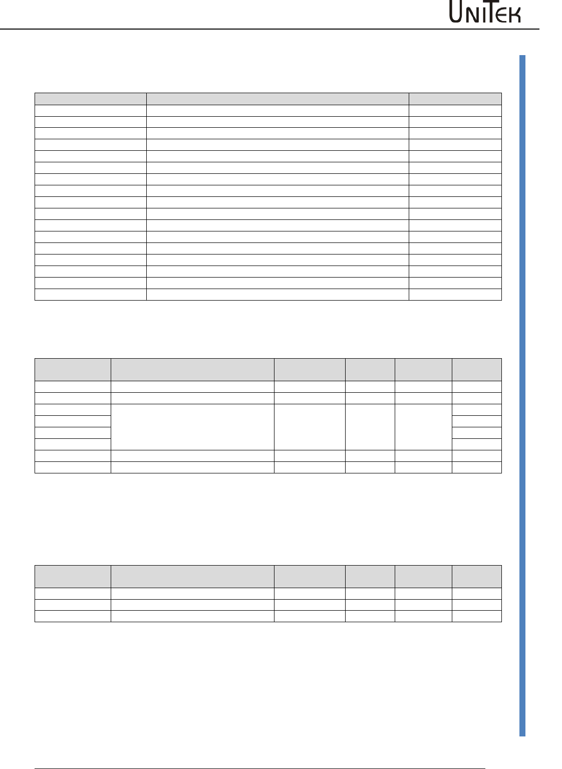
Parameters
Software – Manual N-Drive 3xx
Version 2017 / V1
112
Parameter tables
Logic parameters
Logic BIT
Short symbol
Function
Address
REGID 0xD8
Limit 1
Digital input limit 1 active
Bit 0
Limit 2
Digital input limit 2 active
Bit 1
Din 2
Digital input Din 2 active
Bit 2
Din 1
Digital input Din 1 active
Bit 3
FRG (RUN)
Hardware enable active
Bit 4
Bit 5
Bit 6
Bit 7
Dout 1
Digital output Dout 1 connected
Bit 8
Dout 2
Digital output Dout 2 connected
Bit 9
BTB (Rdy)
Hardware relay output BTB-Rdy connected
Bit 10
GO
Internal enable GO active
Bit 11
Dout 3
Digital output Dout 3 connected
Bit 12
Dout 4
Digital output Dout 4 connected
Bit 13
Bit 14
Bit 15
Logic comparison variable
Short symbol
Function
Setting range
Units
Note
REGID
address
0
Logic signal zero
1/0
Logic
1
Logic signal one
1/0
Logic
VAR1
Numerical value of the entered variable
fields +/-32767 num
0xd1
VAR2
0xd2
VAR3
0xd3
VAR4
0xd4
Ain 1
Analog value input Ain1
+/-32767
num
Ain 2
Analog value input Ain2
+/-32767
num
Interface settings
CAN-BUS
Short symbol
Function
Setting range
Units
Note
REGID
address
Rx ID
Receiving address
dec.
Default 201
0x68
Tx ID
Sending address
dec.
Default 181
0x69
BTR
Transmission rate
see table
hex
0x73
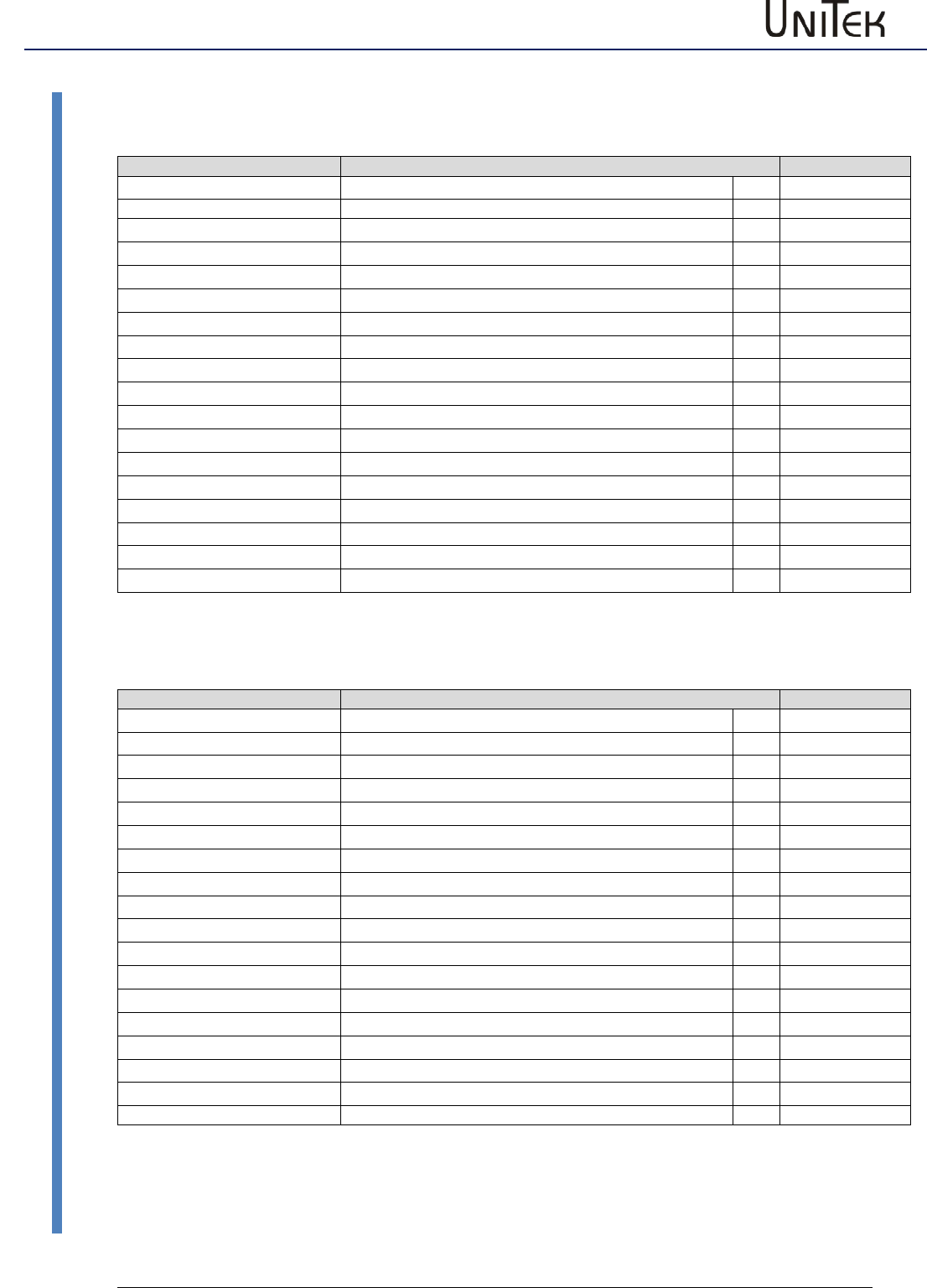
Parameters
113
Version 2017 / V1
Software – Manual N-Drive 3xx
Parameter tables
Messages, errors, warning messages
Error BIT
Error message
Fault
Address
NOREPLY-No RS
RS232 interface not plugged-in or faulty
REGID 0x8f
BADPARAS
Parameter damaged
Bit 0
POWER FAULT
Output stage fault
Bit 1
RFE FAULT
Defective safety circuit (only active with RUN)
Bit 2
BUS TIMEOUT
Transmission fault BUS
Bit 3
FEEDBACK
Faulty encoder signal
Bit 4
POWERVOLTAGE
Missing power voltage supply
Bit 5
MOTORTEMP
Motor temperature too high
Bit 6
DEVICETEMP
Device temperature too high
Bit 7
OVERVOLTAGE
Overvoltage >1.8 x UN
Bit 8
I_PEAK
Over-current 300 %
Bit 9
RACEAWAY
Racing (without command val., wrong direction)
Bit 10
USER
User – fault selection
Bit 11
I2R
Overload
Bit 12
RESERVE
Bit 13
HW-FAIL
Firmware is not compatible with the hardware
Bit 14
BALLAST (device dependent)
Overload of the ballast circuit
Bit 15
Warning BIT
Error message
Fault
Address
REGID 0x8f
WARNING_0
Inconsistent device determination
Bit 16
ILLEGAL STATUS
RUN signal disturbed, EMI
Bit 17
WARNING_2
RFE signal inactive (without RUN)
Bit 18
Bit 19
Bit 20
POWERVOLTAGE
Power voltage too low or missing
Bit 21
MOTORTEMP
Motor temperature >87 %
Bit 22
DEVICETEMP
Device temperature >87 %
Bit 23
OVERVOLTAGE
Overvoltage >1.5 x UN
Bit 24
I_PEAK
Over-current 200 %
Bit 25
Bit 26
Bit 27
I2R
Overload >87 %
Bit 28
Bit 29
Bit 30
BALLAST (device dependent)
Overload of the ballast circuit >87 %
Bit 31
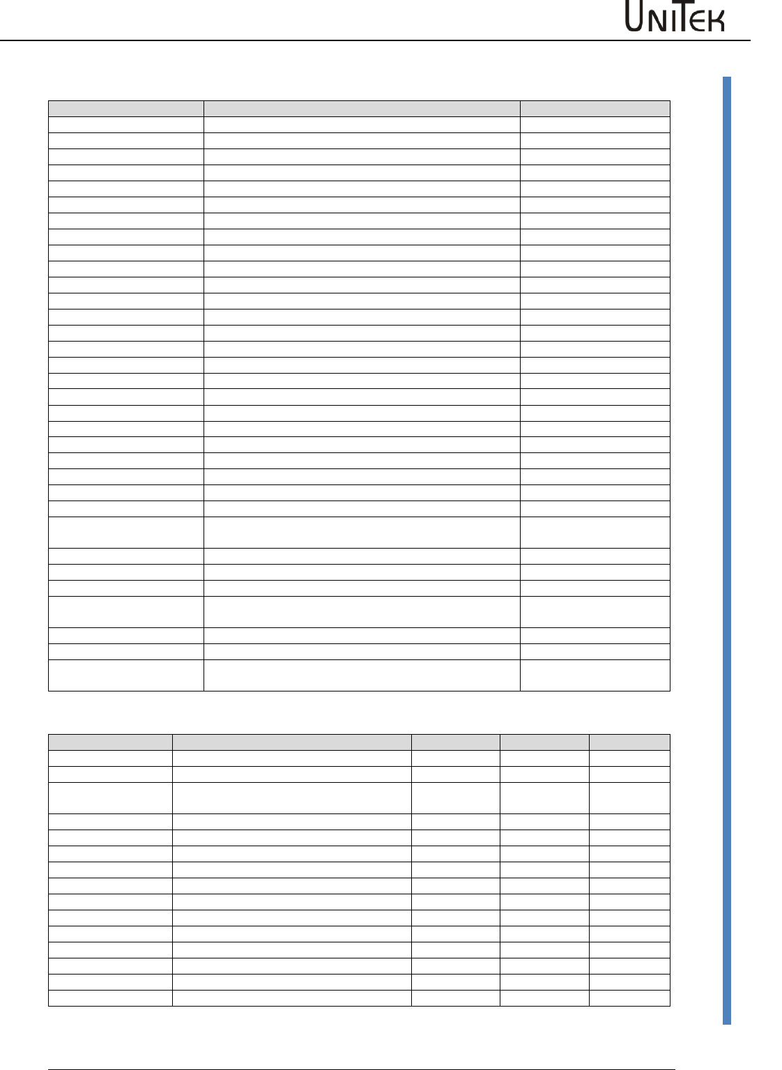
Parameters
Software – Manual N-Drive 3xx
Version 2017 / V1
114
Parameter tables
State BIT
State display
Description
Address
REGID 0x40
Ena
Drive enable (Hardware enable)
Bit 0
NCR0
Speed command value = 0 (drive stopped)
Bit 1
Lim+
Limit switch plus assigned
Bit 2
Lim-
Limit switch minus assigned
Bit 3
OK
Drive in order (no uncontrolled reset)
Bit 4
Icns
Current limit reduced to continuous current
Bit 5
T-Nlim
Speed limited torque mode
Bit 6
P-N
Position control
Bit 7
N-I
Speed control
Bit 8
<N0
Speed inferior to 0.1 %
Bit 9
Rsw
Reference input selected
Bit 10
Cal0
Reference run (Bit 11+Bit12 = Ref. loop travel)
Bit 11
Cal
Reference position identified
Bit 12
Tol
Position within tolerance window
Bit 13
Rdy
Ready (BTB,Rdy)
Bit 14
Brk
active brake
Bit 15
SignMag
inverted command value
Bit 16
Nclip
Speed limiting via switch
Bit 17
Nclip+
Positive speed limiting via switch
Bit 18
Nclip-
Negative speed limiting via switch
Bit 19
lrd-Dig
Current limiting via switch
Bit 20
luse-rchd
Active current reduction
Bit 21
lrd-N
Current reduction via speed
Bit 22
Ird-TI
Current reduction via output stage temperature
Bit 23
Ird-TIR
Current limiting to continuous current via output stage
temperature
Bit 24
>2Hz
Current reduction for frequencies inferior to 2Hz
Bit 25
Ird-TM
Current reduction via motor temperature
Bit 26
Ird-ANA
Current limiting via analog input 2
Bit 27
lwcns
Current value lxt superior to 87 %
Bit 28
RFE-plus
Bit 29
rsvd2:1
Bit 30
Handrad
Handwheel input selected
Bit 31
Measured values
Short symbol
Function
Unit
Range
ID address
Ncmd Ramp
Speed command value after ramp and limit
0x32
N actual
Actual speed value
0x30
Icmd Ramp
Current command value after ramp and
limit
0x26
I actual D
Actual current value D
0x28
I actual Q
Actual current value Q
0x27
I2t
Capacity I2xt
0x45_L
P-Motor
Motor power
0xf6
DC-BUS
Bus circuit voltage
0xeb
P-Regen
0x45_H
Tmotor
Effective motor temperature
0x49
Tigbt
Effective output stage temperature
0x4a
Tair
Effective air temperature in the servo
0x4b
Ireda
Effective current limit
0x48
Parameters
115
Version 2017 / V1
Software – Manual N-Drive 3xx
Parameter tables
Switch and selection settings
Mode BIT
Short symbol
Function
Address
REGID 0x51
Reserve
Bit 0
SPEED = 0
Drive stop
Bit 1
ENABLE OFF
Drive disabled
Bit 2
CANCEL CAL-CYCLE
Reference run stopped
Bit 3
d(status)->CAN
Bit 4
I-clip on
Current limit in % of the type current active
Bit 5
N-clip on
Speed limiting (positive and negative)
Bit 6
Mix ana on
Digital plus analog speed command value
Bit 7
Allow sync
Bit 8
Handwheel
2. feedback as handwheel
Bit 9
Core option BIT
Short symbol
Function
Address
REGID 0x5a
DC-BUS-comp
Analog measured bus circuit value influences Uout
Bit 0
BALLAST_EXT
External ballast resistor
Bit 1
TJ_SPECIAL
Sensor specialties
Bit 2
coast stop
Coast Stop active, coasting to standstill
Bit 3
IISTINVERSE
Inverted actual current value polarity (factory-setting active for
DS450, BAMO-D3)
Bit 4
REFSOFT
Reverse ramp for reference run set from Limit to ‚Dec‘
Bit 5
NOUESP_BTB
BTB signal also at under-voltage error messages
Bit 6
ANA_UESP
Analog ZW-voltage watchdog
Bit 7
BTB_DELAY
Enable delay
Bit 8
Hxinv
Inverted sequence of the Hall signals
Bit 9
H2inv
Hall signal 2 inverted
Bit 10
OL_comp
Sensor specialties
Bit 11
MotorType
Motor selection
Bit 12
MotorType
Motor selection
Bit 13
ANA_0up
Measuring range (Vdc bus, Vdc-Bat) 0 to 5 V (0 = 2.5 to 5 V)
Bit 14
lowbd
Interface RS232 9600 Baud
Bit 15
S-ramp
Selection ‚S-ramp‘ active
Bit 16
4-ramp
Selection ‚4 ramps‘ active
Bit 17
MotBrake
Selection ‚with brake‘ active
Bit 18
ACDC
Bit 19
PWM-Frequenz
Clock frequency setting
Bit 20
PWM-Frequenz
Clock frequency setting
Bit 21
PWM-Frequenz
Clock frequency setting
Bit 22
NTC
Bit 23
delta
Motor phase triangle
Bit 24
DC_1QdirVolt
DC 1-quadrant, direct voltage regulation PWM
Bit 25
DC_field
DC field controller
Bit 26
DEAD_2
Dead band *2
Bit 27
block
Block current at ROT feedback
Bit 28
DC_1QMV
DC 1-quadrant, min. switching losses
Bit 29
DC_1Q3P
DC 1-quadrant, no High-Side, parallel -UB switch
Bit 30
Frd<10Hz
<10 Hz switching frequence set to 4 kHz
Bit 31

Parameters
Software – Manual N-Drive 3xx
Version 2017 / V1
116
Parameter tables
Monitor parameters
Short symbol
Function
Unit
Range
ID address
Ncmd Ramp
Speed command value after ramp and
limit
num
0 to +/-32767
0x32
N actual
Actual speed value
num
0 to +/-32767
0x30
Icmd Ramp
Current command value after ramp and
limit
num
0 to 600
0x26
Iact monitor
Actual current value (filtered)
I actual D
Actual current value D (reactive current)
num
0 to 600
0x28
I actual Q
Actual current value Q (active current)
num
0 to 600
0x27
I2t
Capacity I2xt
num
0 to 4000
0x45_L
P-Motor
Motor power
num
0 to 4000
0xf6
DC-BUS
Bus circuit voltage
num
0 to +/-32767
0xeb
P-Regen
Ballast power
num
0 to 4000
0x45_H
Tmotor
Effective motor temperature
num
0 to 32767
0x49
Tigbt
Effective output stage temperature
num
0 to 32767
0x4a
Tair
Effective air temperature in the servo
num
0 to 32767
0x4b
Ireda
Effective current limit
num
0 to 600
0x48
Vout
Output voltage
num
0 to 4000
0x8a
