Digi XBee3 Cellular LTE Cat 1 Smart Modem User Guide LTEC1 Users 90002253
User Manual:
Open the PDF directly: View PDF ![]() .
.
Page Count: 178 [warning: Documents this large are best viewed by clicking the View PDF Link!]
- Digi XBee3 Cellular LTE Cat 1 Smart Modem User Guide
- Get started with the XBee Smart Modem Development Kit
- Connection examples
- Get started with MicroPython
- Technical specifications
- Hardware
- Antenna recommendations
- Design recommendations
- Cellular connection process
- Modes
- Sleep modes
- Power saving features
- Serial communication
- SPI operation
- File system
- Socket behavior
- Supported sockets
- Socket timeouts
- Socket limits in API mode
- Enable incoming TCP connections
- API mode behavior for outgoing TCP and SSL connections
- API mode behavior for outgoing UDP data
- API mode behavior for incoming TCP connections
- API mode behavior for incoming UDP data
- Transparent mode behavior for outgoing TCP and SSL connections
- Transparent mode behavior for outgoing UDP data
- Transparent mode behavior for incoming TCP connections
- Transparent mode behavior for incoming UDP connections
- Transport Layer Security (TLS)
- AT commands
- Special commands
- Cellular commands
- Network commands
- Addressing commands
- Serial interfacing commands
- I/O settings commands
- D0 (DIO0/AD0)
- D1 (DIO1/AD1)
- D2 (DIO2/AD2)
- D3 (DIO3/AD3)
- D4 (DIO4)
- D5 (DIO5/ASSOCIATED_INDICATOR)
- D6 (DIO6/RTS)
- D7 (DIO7/CTS)
- D8 (DIO8/SLEEP_REQUEST)
- P0 (DIO10/PWM0 Configuration)
- P1 (DIO11/PWM1 Configuration)
- P2 (DIO12 Configuration)
- P3 (DIO13/DOUT)
- P4 (DIO14/DIN)
- PD (Pull Direction)
- PR (Pull-up/down Resistor Enable)
- M0 (PWM0 Duty Cycle)
- I/O sampling commands
- Sleep commands
- Command mode options
- MicroPython commands
- Firmware version/information commands
- Diagnostic interface commands
- Execution commands
- File system commands
- Operate in API mode
- API frames
- Configure the XBee Smart Modem using Digi Remote Manager
- Troubleshooting
- Regulatory information

Digi XBee3® Cellular LTE Cat 1
Smart Modem
User Guide

Revision history—90002253
Revision Date Description
AJanuary
2018
Initial release of the document.
B February
2018
Added instructions for sending an SCI request to Remote Manager. Added
details on SPI operation. Added antenna keepout area for Bluetooth. Updated
specifications for Bluetooth.
C June
2018
0B software release. Added file system and TLS sections, ATcommands and
related changes.
D August
2018
Updated list of cipher suites. Updated Get Started section.
Trademarks and copyright
Digi, Digi International, and the Digi logo are trademarks or registered trademarks in the United
States and other countries worldwide. All other trademarks mentioned in this document are the
property of their respective owners.
© 2018 Digi International Inc. All rights reserved.
Disclaimers
Information in this document is subject to change without notice and does not represent a
commitment on the part of Digi International. Digi provides this document “as is,” without warranty of
any kind, expressed or implied, including, but not limited to, the implied warranties of fitness or
merchantability for a particular purpose. Digi may make improvements and/or changes in this manual
or in the product(s) and/or the program(s) described in this manual at any time.
Warranty
To view product warranty information, go to the following website:
www.digi.com/howtobuy/terms
Send comments
Documentation feedback: To provide feedback on this document, send your comments to
techcomm@digi.com.
Customer support
Digi Technical Support: Digi offers multiple technical support plans and service packages to help our
customers get the most out of their Digi product. For information on Technical Support plans and
pricing, contact us at +1 952.912.3444 or visit us at www.digi.com/support.
Digi XBee3 Cellular LTE Cat 1 Smart Modem User Guide 2

Contents
Digi XBee3 Cellular LTE Cat 1 Smart Modem User Guide
Applicable firmware and hardware 11
SIM cards 11
Get started with the XBee Smart Modem Development Kit
Identify the kit contents 13
Connect the hardware 14
XBIB-U-DEV reference 16
Cellular service 17
Configure the device using XCTU 18
Add a device 18
Check for cellular registration and connection 19
Update to the latest firmware 19
Connection examples
Connect to the Echo server 22
Debugging 23
Connect to the ELIZA server 24
Debugging 25
Connect to the Daytime server 26
Debugging 27
Send an SMS message to a phone 28
Debugging 29
Perform a (GET) HTTP request 30
Debugging 31
Get started with CoAP 32
CoAP terms 32
CoAP quick start example 32
Configure the device 33
Example: manually perform a CoAPrequest 33
Example: use Python to generate a CoAP message 34
Connect to a TCP/IP address 37
Debugging 37
Get started with MQTT 39
Example: MQTT connect 39
Send a connect packet 41
Example: send messages (publish) with MQTT 42
Example: receive messages (subscribe) with MQTT 43
Digi XBee3 Cellular LTE Cat 1 Smart Modem User Guide 3

Digi XBee3 Cellular LTE Cat 1 Smart Modem User Guide 4
Use MQTT over the XBee Cellular Modem with a PC 44
Software libraries 47
Get started with MicroPython
About MicroPython 48
Why use MicroPython 48
MicroPython on the XBee Smart Modem 48
Use XCTU to enter the MicroPython environment 49
Use the MicroPython Terminal in XCTU 49
Troubleshooting 49
Example: hello world 50
Example: turn on an LED 50
Example: code a request help button 51
Enter MicroPython paste mode 51
Catch a button press 52
Send a text (SMS) when the button is pressed 53
Add the time the button was pressed 54
Exit MicroPython mode 55
Other terminal programs 55
Tera Term for Windows 56
Use picocom in Linux 57
Technical specifications
Interface and hardware specifications 60
RF characteristics 60
Networking specifications 60
Power requirements 60
Power consumption 61
Electrical specifications 61
Regulatory approvals 62
Hardware
Mechanical drawings 64
Pin signals 64
Pin connection recommendations 65
RSSI PWM 66
SIM card 66
The Associate LED 66
Antenna recommendations
Antenna connections 69
Keepout area 70
Through-hole keepout 71
Antenna placement 71
Design recommendations
Cellular component firmware updates 73

Digi XBee3 Cellular LTE Cat 1 Smart Modem User Guide 5
USB Direct design 73
Power supply considerations 73
Recommended application circuit 74
Heat considerations and testing 74
Heat sink guidelines 75
Add a fan to provide active cooling 76
Cellular connection process
Connecting 78
Cellular network 78
Data network connection 78
Data communication with remote servers (TCP/UDP) 78
Disconnecting 78
SMS encoding 79
Modes
Select an operating mode 81
Transparent operating mode 82
API operating mode 82
Bypass operating mode 82
Enter Bypass operating mode 82
Leave Bypass operating mode 83
Restore cellular settings to default in Bypass operating mode 83
USB direct mode 83
Enable USB direct mode 83
Command mode 83
Enter Command mode 84
Troubleshooting 84
Send AT commands 84
Response to AT commands 85
Apply command changes 85
Make command changes permanent 85
Exit Command mode 85
MicroPython mode 86
Sleep modes
About sleep modes 88
Normal mode 88
Pin sleep mode 88
Cyclic sleep mode 88
Cyclic sleep with pin wake up mode 88
Connected sleep mode 88
The sleep timer 89
MicroPython sleep behavior 89
Power saving features
Airplane mode 91

Digi XBee3 Cellular LTE Cat 1 Smart Modem User Guide 6
Serial communication
Serial interface 93
Serial data 93
UART data flow 93
Serial buffers 93
CTS flow control 94
RTS flow control 94
Enable UART or SPI ports 94
SPI operation
SPI communications 96
Full duplex operation 97
Low power operation 98
Select the SPI port 98
Force UART operation 99
Data format 99
File system
Overview of the file system 101
Directory structure 101
Paths 101
Secure files 101
XCTU interface 102
Encrypt files 102
Socket behavior
Supported sockets 104
Socket timeouts 104
Socket limits in API mode 104
Enable incoming TCP connections 104
API mode behavior for outgoing TCP and SSL connections 105
API mode behavior for outgoing UDP data 105
API mode behavior for incoming TCP connections 105
API mode behavior for incoming UDP data 106
Transparent mode behavior for outgoing TCP and SSL connections 106
Transparent mode behavior for outgoing UDP data 107
Transparent mode behavior for incoming TCP connections 107
Transparent mode behavior for incoming UDP connections 107
Transport Layer Security (TLS)
TLS AT commands 109
Transparent mode and TLS 110
API mode and TLS 110
Key formats 110
Certificate formats 110
Certificate limitations 110
Cipher suites 110

Digi XBee3 Cellular LTE Cat 1 Smart Modem User Guide 7
Server Name Indication (SNI) 111
AT commands
Special commands 113
AC (Apply Changes) 113
FR (Force Reset) 113
RE command 113
WR (Write) 113
Cellular commands 114
PH (Phone Number) 114
S# (ICCID) 114
IM (IMEI) 114
MN (Operator) 114
MV (Modem Firmware Version) 115
DB (Cellular Signal Strength) 115
AN (Access Point Name) 115
CP (Carrier Profile) 115
OA (Operating APN) 116
AM (Airplane Mode) 116
DV (Antenna Diversity) 116
Network commands 117
IP (IP Protocol) 117
TL (SSL/TLS Protocol Version) 117
$0 (SSL/TLS Profile 0) 118
$1 (SSL/TLS Profile 1) 118
$2 (SSL/TLS Profile 2) 118
TM (IP Client Connection Timeout) 119
TS (IP Server Connection Timeout) 119
DO (Device Options) 119
EQ (Remote Manager FQDN) 120
Addressing commands 120
SH (Serial Number High) 120
SL (Serial Number Low) 120
MY (Module IP Address) 120
P# (Destination Phone Number) 121
N1 (DNS Address) 121
N2 (DNS Address) 121
DL (Destination Address) 121
OD (Operating Destination Address) 122
DE (Destination Port) 122
C0 (Source Port) 122
LA (Lookup IP Address of FQDN) 122
Serial interfacing commands 123
BD (Baud Rate) 123
NB (Parity) 123
SB (Stop Bits) 124
RO (Packetization Timeout) 124
TD (Text Delimiter) 124
FT (Flow Control Threshold) 125
AP (API Enable) 125
I/O settings commands 125
D0 (DIO0/AD0) 125
D1 (DIO1/AD1) 126
D2 (DIO2/AD2) 126

Digi XBee3 Cellular LTE Cat 1 Smart Modem User Guide 8
D3 (DIO3/AD3) 127
D4 (DIO4) 127
D5 (DIO5/ASSOCIATED_INDICATOR) 128
D6 (DIO6/RTS) 128
D7 (DIO7/CTS) 129
D8 (DIO8/SLEEP_REQUEST) 129
P0 (DIO10/PWM0 Configuration) 130
P1 (DIO11/PWM1 Configuration) 130
P2 (DIO12 Configuration) 131
P3 (DIO13/DOUT) 131
P4 (DIO14/DIN) 132
PD (Pull Direction) 132
PR (Pull-up/down Resistor Enable) 132
M0 (PWM0 Duty Cycle) 133
I/O sampling commands 133
TP (Temperature) 134
IS (Force Sample) 134
Sleep commands 135
SM (Sleep Mode) 135
SP (Sleep Period) 135
ST (Wake Time) 135
SO (Sleep Options) 136
Command mode options 136
CC (Command Sequence Character) 136
CT (Command Mode Timeout) 136
CN (Exit Command mode) 137
GT (Guard Times) 137
MicroPython commands 137
PS (Python Startup) 137
PY (MicroPython Command) 138
Firmware version/information commands 138
VR (Firmware Version) 139
VL (Verbose Firmware Version) 139
HV (Hardware Version) 139
AI (Association Indication) 139
HS (Hardware Series) 140
CK (Configuration CRC) 140
Diagnostic interface commands 140
DI (Remote Manager Indicator) 140
CI (Protocol/Connection Indication) 141
Execution commands 143
NR (Network Reset) 143
!R (Modem Reset) 143
File system commands 143
Error responses 144
ATFS (File System) 144
ATFS PWD 144
ATFS CDdirectory 144
ATFS MDdirectory 144
ATFS LS [directory] 144
ATFS PUTfilename 144
ATFS XPUTfilename 145
ATFS HASHfilename 145
ATFS GETfilename 145
ATFS MVsource_pathdest_path 145

Digi XBee3 Cellular LTE Cat 1 Smart Modem User Guide 9
ATFS RMfile_or_directory 145
ATFS INFO 145
ATFSFORMAT confirm 145
Operate in API mode
API mode overview 147
Use the AP command to set the operation mode 147
API frame format 147
API operation (AP parameter = 1) 147
API operation with escaped characters (AP parameter = 2) 148
API frames
AT Command - 0x08 152
Transmit (TX) SMS - 0x1F 153
Transmit (TX) Request: IPv4 - 0x20 154
Tx Request with TLS Profile - 0x23 156
AT Command Response - 0x88 158
Transmit (TX) Status - 0x89 159
Modem Status - 0x8A 161
Receive (RX) Packet: SMS - 0x9F 162
Receive (RX) Packet: IPv4 - 0xB0 163
Configure the XBee Smart Modem using Digi Remote Manager
Create a Remote Manager account 165
Get the XBee Smart Modem IMEI number 165
Add a XBee Smart Modem to Remote Manager 165
Update the firmware 166
Update the firmware using web services 166
Example: update the XBee firmware synchronously with Python 3.0 166
Example: use the device's firmware image to update the XBee firmware synchronously 167
Troubleshooting
Cannot find the serial port for the device 170
Condition 170
Solution 170
Other possible issues 171
Enable Virtual COM port (VCP) on the driver 171
Correct a macOS Java error 172
Condition 172
Solution 172
Unresponsive cellular component in Bypass mode 173
Condition 173
Solution 173
Not on expected network after APN change 174
Condition 174
Solution 174
Syntax error at line 1 174
Solution 174
Error Failed to send SMS 174

Digi XBee3 Cellular LTE Cat 1 Smart Modem User Guide 10
Solution 174
Regulatory information
Modification statement 176
Interference statement 176
FCC Class B digital device notice 176
RF exposure 177
FCC-approved antennas 177
Bluetooth antennas 177
Dipole antennas 177
Flex PCB antennas 177
Cellular antennas 178
Labeling requirements for the host device 178

Digi XBee3 Cellular LTE Cat 1 Smart Modem User
Guide
The XBee Smart Modem contains a u-blox R410M-02B module that also supports NB-IoT. Digi has not
released support for the NB-IoT feature. Contact your sales representative if you would like more
information about our roadmap to support NB-IoT.
The XBee Smart Modem is an embedded Long-Term Evolution (LTE) Category 1 cellular module that
provides original equipment manufacturers (OEMs) with a simple way to integrate cellular
connectivity into their devices.
The XBee Smart Modem enables OEMs to quickly integrate cutting edge 4G cellular technology into
their devices and applications without dealing with the painful, time-consuming, and expensive FCC
and carrier end-device certifications.
With the full suite of standard XBee API frames and AT commands, existing XBee customers can
seamlessly transition to this new device with only minor software adjustments. When OEMs add the
XBee Smart Modem to their product, they create a future-proof design with flexibility to switch
between wireless protocols or frequencies as needed.
You can read some frequently asked questions here.
Applicable firmware and hardware
This manual supports the following firmware:
n310xx
It supports the following hardware:
nXB3-C-A1-UT-xxx
SIM cards
The XBee Smart Modem requires a 4FF (Nano) size SIM card. The SIM interface supports both 1.8 V
and 3 V SIM types.
Digi XBee3 Cellular LTE Cat 1 Smart Modem User Guide 11

Get started with the XBee Smart Modem
Development Kit
This section describes how to connect the hardware in the XBee Smart Modem Development Kit, and
provides some examples you can use to communicate with the device.
1. Identify the kit contents
2. Connect the hardware
3. Review the development board
4. Set up cellular service
5. Configure the device using XCTU
6. Use one of the following methods to verify your cellular connection:
nConnect to the Echo server
nConnect to the ELIZA server
nConnect to the Daytime server
7. Review additional connection examples to help you learn how to use the device. See
Connection examples.
8. Review introductory MicroPython examples. See Get started with MicroPython.
Digi XBee3 Cellular LTE Cat 1 Smart Modem User Guide 12
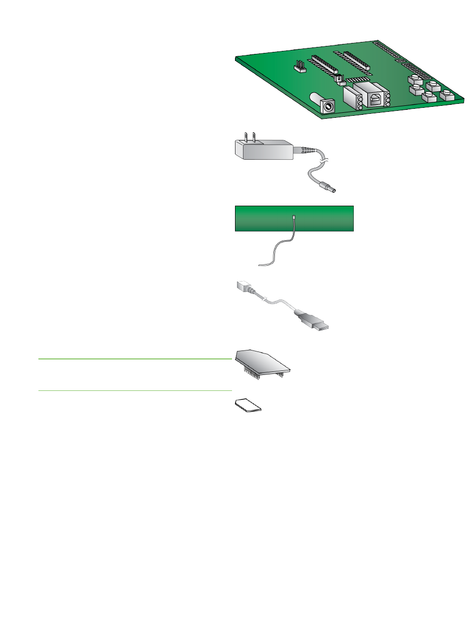
Identify the kit contents
The Developer's kit includes the following:
One XBIB-U-DEV board
One 12 V power supply
Two cellular antennas with U.FL connectors
One USB cable
One XBee Smart Modem
Note The XBee Smart Modem comes
attached to the board in ESDwrap.
One SIMcard
Digi XBee3 Cellular LTE Cat 1 Smart Modem User Guide 13
Get started with the XBee Smart Modem Development Kit Connect the hardware
Digi XBee3 Cellular LTE Cat 1 Smart Modem User Guide 14
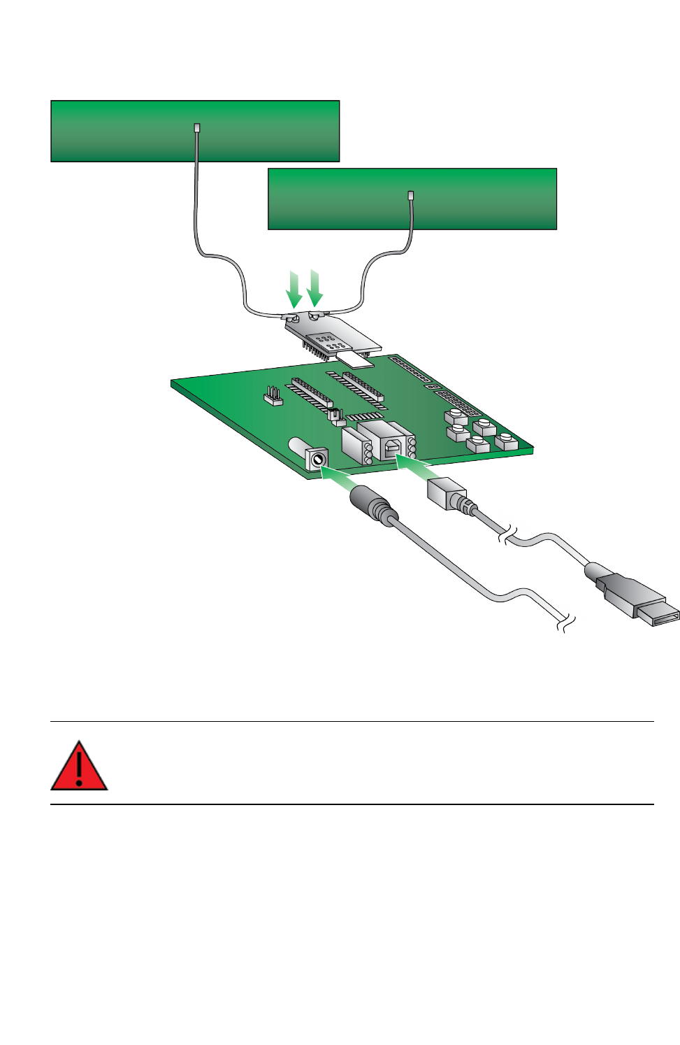
Connect the hardware
1. The XBee Smart Modem should already be plugged into the XBIB-U-DEV board.
2. The SIMcard should be already be inserted into the XBee Smart Modem. If not, install the
SIMcard into the XBee Smart Modem.
WARNING! Never insert or remove the SIM card while the device is powered!
3. Connect the antennas to the XBee Smart Modem by aligning the U.FL connectors carefully,
then firmly pressing straight down to seat the connector. You should hear a snap when the
antenna attaches correctly. U.FL is fragile and is not designed for multiple insertions, so
exercise caution when connecting or removing the antennas. We recommend using a U.FL
removal tool.

Get started with the XBee Smart Modem Development Kit Connect the hardware
Digi XBee3 Cellular LTE Cat 1 Smart Modem User Guide 15
4. Plug the 12 V power supply to the power jack on the development board.
5. Connect the USB cable from a PC to the USB port on the development board. The computer
searches for a driver, which can take a few minutes to install.

Get started with the XBee Smart Modem Development Kit XBIB-U-DEV reference
Digi XBee3 Cellular LTE Cat 1 Smart Modem User Guide 16
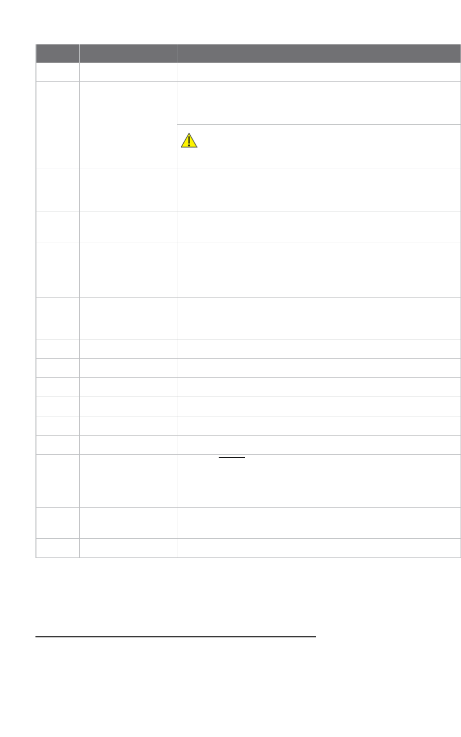
XBIB-U-DEV reference
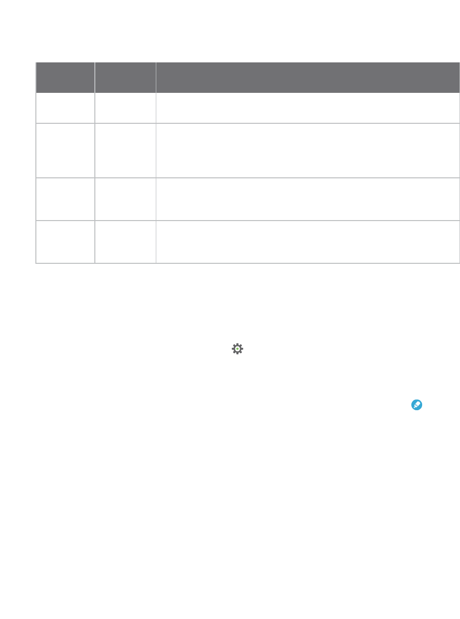
This picture shows the XBee USB development board and the table that follows explains the callouts
in the picture.
Get started with the XBee Smart Modem Development Kit Cellular service
Digi XBee3 Cellular LTE Cat 1 Smart Modem User Guide 17
Number Item Description
1 Programmingheader Header used to program XBee programmable devices.
2 Self power module Advanced users only—voids the warranty. Depopulate R31 to
power the device using V+ and GND from J2 and J5. You can
connect sense lines to S+ and S- for sensing power supplies.
CAUTION: Voltage is not regulated. Applying the incorrect
voltage can cause fire and serious injury.1
3 Current testing Depopulating R31 allows a current probe to be inserted across P6
terminals. The current though P6/R31 powers the device only.
Other supporting circuitry is powered by a different trace.
4 Loopback jumper Populating P8 with a loopback jumper causes serial transmissions
both from the device and from the USB to loopback.
5 DC barrel plug: 6-20V Greater than 500 mA loads require a DC supply for correct
operation. Plug in the external power supply prior to the USB
connector to ensure that proper USB communications are not
interrupted.
6 LED indicator Yellow: Modem sending serial/UART data to host.
Green: Modem receiving serial/UART data from host.
Red: Associate.
7 USB
8 RSSI indicator See RSSI PWM. On the XBIB-U, more lights are better.
9 User buttons Connected to DIO lines for user implementation.
10 Reset button
11 SPI power Connect to the power board from 3.3 V.
12 SPI Only used for surface-mount devices.
13 Indicator LEDs DS5: ON/SLEEP
DS2: DIO12, the LED illuminates when driven low.
DS3: DIO11, the LED illuminates when driven low.
DS4: DIO4, the LED illuminates when driven low.
14 Through-hole XBee
sockets
15 20-pin header Maps to standard through-hole XBee pins.
Cellular service
Digi now offers Cellular Bundled Service plans. This service includes preconfigured cellular data
options that are ideal for IoT applications, bundled together with Digi Remote Manager for customers
1Powering the board with J2 and J5 without R31 removed can cause shorts if the USB or barrel plug power are
connected. Applying too high a voltage destroys electronic circuitry in the device and other board components
and/or can cause injury.
Get started with the XBee Smart Modem Development Kit Configure the device using XCTU
Digi XBee3 Cellular LTE Cat 1 Smart Modem User Guide 18
who want to remotely monitor and manage their devices. To learn more, or obtain the plan that is
right for your needs, contact us:
nBy phone: 1-877-890-4014 (USA/toll free) or +1-952-912-3456 (International). Select the
Wireless Plan Support or Activation option in the menu.
nBy email: Data.Plan.QuoteDesk@digi.com.
The XBee Cellular kit includes six months of free cellular service.1
Configure the device using XCTU
XBee Configuration and Test Utility (XCTU) is a multi-platform program that enables users to interact
with Digi radio frequency (RF) devices through a graphical interface. The application includes built-in
tools that make it easy to set up, configure, and test Digi RF devices.
XCTU does not work directly over an SPI interface.
For instructions on downloading and using XCTU, see the XCTU User Guide.
To use XCTU, you may need to install FTDI Virtual COMport (VCP)drivers onto your computer. Click
here to download the drivers for your operating system.
Note If you are on a macOS computer and encounter problems installing XCTU, see Correct a macOS
Java error.
Add a device
These instructions show you how to add the XBee Smart Modem to XCTU.
If XCTU does not find your serial port, see Cannot find the serial port for the device and Enable Virtual
COM port (VCP) on the driver.
1. Launch XCTU .
Note XCTU's Update the radio module firmware dialog box may open and will not allow you to
continue until you click Update or Cancel on the dialog.
2. Click Help >Check for XCTUUpdates to ensure you are using the latest version of XCTU.
3. Click the Discover radio modules button .
4. In the Discover radio devices dialog, select the serial ports where you want to look for XBee
modules, and click Next.
5. In the Set port parameters window, maintain the default values and click Finish.
6. As XCTU locates radio modules, they appear in the Discovering radio modules dialog box.
If your module could not be found, XCTU displays the Could not find any radio module dialog
providing possible reasons why the module could not be added.
1Six months of free cellular service assumes a rate of 5 Mb/month. If you exceed a limit of 30 Mb during the six
month period your SIM will be deactivated.
Get started with the XBee Smart Modem Development Kit Configure the device using XCTU
Digi XBee3 Cellular LTE Cat 1 Smart Modem User Guide 19
Check for cellular registration and connection
In the following examples, proper cellular network registration and address assignment must occur
successfully. The LED on the development board blinks when the XBee Smart Modem is registered to
the cellular network; see The Associate LED. If the LEDremains solid, registration has not occurred
properly.
Registration can take several minutes.
Note Make sure you are in an area with adequate cellular network reception or the XBee Smart
Modem will not make the connection.
Note Check the antenna connections if the device has trouble connecting to the network.
In addition to the LED confirmation, you can check the AT commands below in XCTU to check the
registration and connection. To view these commands:
1. Open XCTU and Add a device.
2. Click the Configuration working mode button.
3. Select a device from the Radio Modules list. XCTU displays the current firmware settings for
that device.
4. Update to the latest firmware.
Note To search for an ATcommand in XCTU, use the search box .
The relevant commands are:
nAI (Association Indication) reads zero when the device successfully registers to the cellular
network. If it reads 23 it is connecting to the Internet; 22 means it is registering to the cellular
network.
nMY (Module IPAddress) should display a valid IPaddress. If it reads 0.0.0.0, it has not
registered yet.
Note To read a command's value, click the Read button next to the command.
Update to the latest firmware
Firmware is the program code stored in the device's persistent memory that provides the control
program for the device. Use XCTU to update the firmware.
Note If you have already updated the firmware in a previous step, this process is not necessary.
1. Click the Configuration working modes button .
2. Select a local XBee module from the Radio Modules list.

Get started with the XBee Smart Modem Development Kit Configure the device using XCTU
Digi XBee3 Cellular LTE Cat 1 Smart Modem User Guide 20
3. Click the Update firmware button to ensure you have the most current firmware.
The Update firmware dialog displays the available and compatible firmware for the selected
XBee module.
4. Make sure you check the Force the module to maintain its current configuration box and
then click Update.
5. Select the product family of the XBee module, the function set, and the latest firmware version.
6. Click Update. A dialog displays update progress. Click Show details for details of the firmware
update process.
See How to update the firmware of your modules in the XCTU User Guide for more information.

Connection examples
The following examples provide some additional scenarios you can try to get familiar with the XBee
Smart Modem.
Connect to the Echo server 22
Connect to the ELIZA server 24
Connect to the Daytime server 26
Send an SMS message to a phone 28
Perform a (GET) HTTP request 30
Get started with CoAP 32
Connect to a TCP/IP address 37
Get started with MQTT 39
Software libraries 47
Digi XBee3 Cellular LTE Cat 1 Smart Modem User Guide 21
Connect to the Echo server
This server echoes back the messages you type.
The following table explains the AT commands that you use in this example.
At
command Value Description
IP (IP
Protocol)
1 Set the expected transmission mode to TCP communications.
TD (Text
Delimiter)
D (0x0D) The text delimiter to be used for Transparent mode, as an ASCII hex
code. No information is sent until this character is entered, unless the
maximum number of characters has been reached. Set to zero to
disable text delimiter checking. Set to Dfor a carriage return.
DL
(Destination
Address)
52.43.121.77 The target IPaddress of the echo server.
DE
(Destination
Port)
0x2329 The target port number of the echo server.
To communicate with the Echo server:
1. Ensure that the device is set up correctly with the SIM card installed and the antennas
connected as described in Connect the hardware.
2. Open XCTU and Add a device.
3. Click the Configuration working mode button.
4. Select a device from the Radio Modules list. XCTU displays the current firmware settings for
that device.
5. To switch to TCP communication, in the IP field, select 1 and click the Write button .
6. To enable the XBee Smart Modem to recognize carriage return as a message delimiter, in the
TD field, type Dand click the Write button.
7. To enter the destination address of the echo server, in the DL field, type 52.43.121.77 and click
the Write button.
8. To enter the destination IP port number, in the DE field, type 2329 and click the Write button.
Digi XBee3 Cellular LTE Cat 1 Smart Modem User Guide 22
Connection examples Connect to the Echo server
Digi XBee3 Cellular LTE Cat 1 Smart Modem User Guide 23
9. Click the Consoles working mode button on the toolbar to open a serial console to the
device. For instructions on using the Console, see the AT console topic in the XCTU User Guide.
10. Click the Open button to open a serial connection to the device.
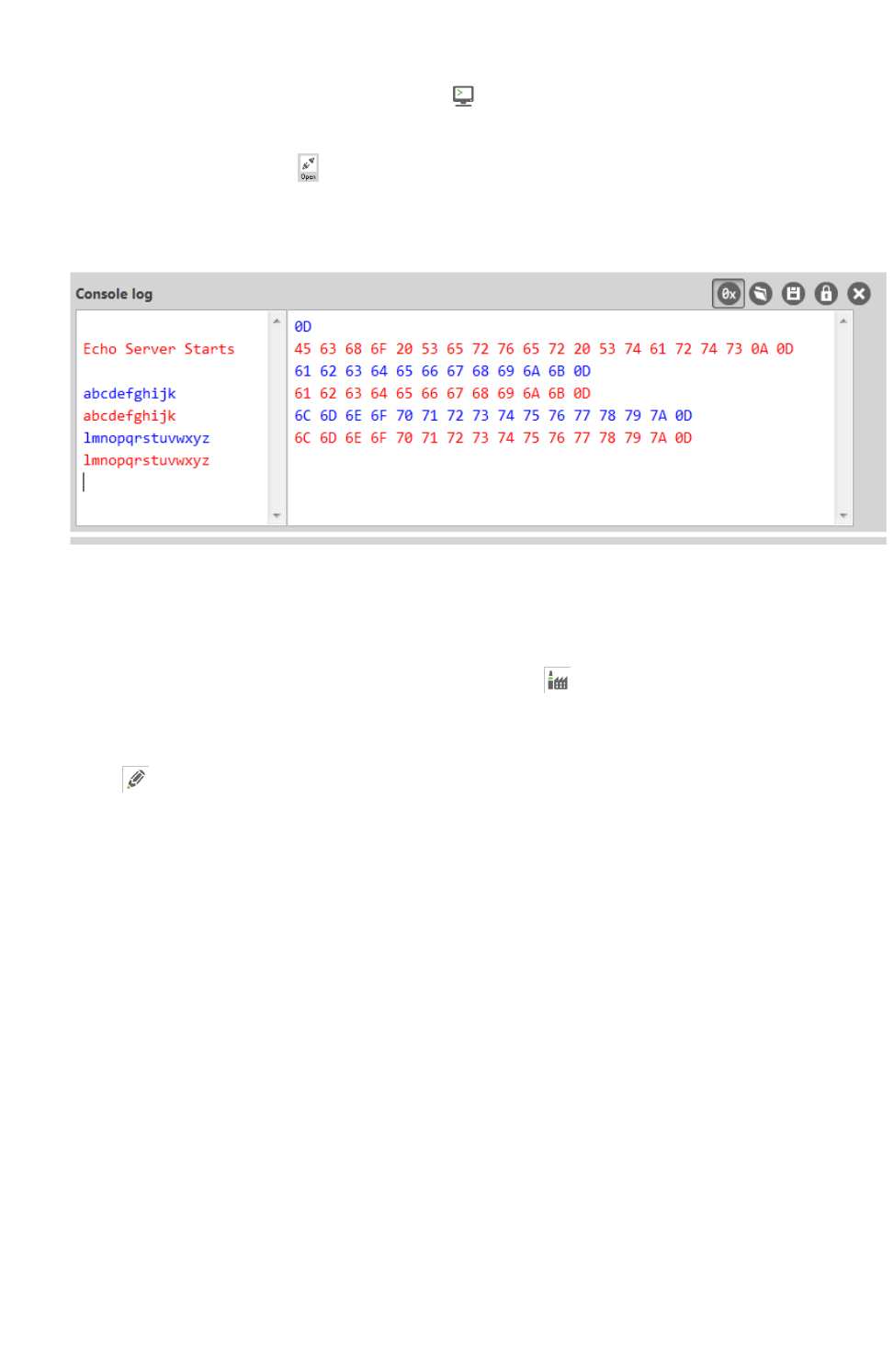
11. Click in the left pane of the Console log, then type in the Console to talk to the echo server.
The following screenshot provides an example of this chat.
Debugging
If you experience problems with the settings in this example, you can load the default settings in
XCTU:
1. On the Configuration toolbar, click the Default button to load the default values
established by the firmware, and click Yes to confirm.
2. Factory settings are loaded but not written to the device. To write them, click the Write button
on the toolbar.
Connection examples Connect to the ELIZA server
Digi XBee3 Cellular LTE Cat 1 Smart Modem User Guide 24
Connect to the ELIZA server
You can use the XBee Smart Modem to chat with the ELIZA Therapist Bot. ELIZAis an artificial
intelligence (AI) bot that emulates a therapist and can perform simple conversations.
The following table explains the AT commands that you use in this example.
At command Value Description
IP (IP Protocol) 1 Set the expected transmission mode to TCP
communications.
DL (Destination
Address)
52.43.121.77 The target IP address of the ELIZA server.
DE (Destination Port) 0x2328 The target port number of the ELIZA server.
To communicate with the ELIZA Therapist Bot:
1. Ensure that the device is set up correctly with the SIM card installed and the antennas
connected as described in Connect the hardware.
2. Open XCTU and Add a device.
3. Click the Configuration working mode button.
4. Select a device from the Radio Modules list. XCTU displays the current firmware settings for
that device.
5. To switch to TCP communication, in the IP field, select 1 and click the Write button .
6. To enter the destination address of the ELIZATherapist Bot, in the DL field, type 52.43.121.77
and click the Write button.
7. To enter the destination IP port number, in the DE field, type 2328 and click the Write button.
8. Click the Consoles working mode button on the toolbar to open a serial console to the
device. For instructions on using the Console, see the AT console topic in the XCTU User Guide.
9. Click the Open button to open a serial connection to the device.
10. Click in the left pane of the Console log, then type in the Console to talk to the ELIZA Therapist
Bot. The following screenshot provides an example of this chat with the user's text in blue.
Connection examples Connect to the ELIZA server
Digi XBee3 Cellular LTE Cat 1 Smart Modem User Guide 25
Debugging
If you experience problems with the settings in this example, you can load the default settings in
XCTU:
1. On the Configuration toolbar, click the Default button to load the default values
established by the firmware, and click Yes to confirm.
2. Factory settings are loaded but not written to the device. To write them, click the Write button
on the toolbar.

Connection examples Connect to the Daytime server
Digi XBee3 Cellular LTE Cat 1 Smart Modem User Guide 26
Connect to the Daytime server
The Daytime server reports the current Coordinated Universal Time (UTC) value responding to any
user input.
The following table explains the AT commands that you use in this example.
At
command Value Description
IP (IP
Protocol)
1 Set the expected transmission mode to TCP communications.
DL
(Destination
Address)
52.43.121.77 The target IP of the Daytime server.
DE
(Destination
Port)
0x232A The target port number of the Daytime server.
TD (Text
Delimiter)
0The text delimiter to be used for Transparent mode, as an ASCII hex
code. No information is sent until this character is entered, unless the
maximum number of characters has been reached. Set to zero to
disable text delimiter checking.
To communicate with the Daytime server:
1. Ensure that the device is set up correctly with the SIM card installed and the antennas
connected as described in Connect the hardware.
2. Open XCTU and Add a device.
3. Click the Configuration working mode button.
4. Select a device from the Radio Modules list. XCTU displays the current firmware settings for
that device.
5. To switch to TCP communication, in the IP field, select 1 and click the Write button .
6. To enter the destination address of the daytime server, in the DL field, type 52.43.121.77 and
click the Write button.
7. To enter the destination IP port number, in the DE field, type 232A and click the Write button.
8. To disable text delimiter checking, in the TD field, type 0and click the Write button.
9. Click the Consoles working mode button on the toolbar to open a serial console to the
device. For instructions on using the Console, see the AT console topic in the XCTU User Guide.
10. Click the Open button to open a serial connection to the device.
11. Click in the left pane of the Console log, then type in the Console to query the Daytime server.
The following screenshot provides an example of this chat.
Connection examples Connect to the Daytime server
Digi XBee3 Cellular LTE Cat 1 Smart Modem User Guide 27
Debugging
If you experience problems with the settings in this example, you can load the default settings in
XCTU:
1. On the Configuration toolbar, click the Default button to load the default values
established by the firmware, and click Yes to confirm.
2. Factory settings are loaded but not written to the device. To write them, click the Write button
on the toolbar.
Connection examples Send an SMS message to a phone
Digi XBee3 Cellular LTE Cat 1 Smart Modem User Guide 28
Send an SMS message to a phone
The XBee Smart Modem can send and receive Short Message Service (SMS) transmissions (text
messages) while in Transparent mode. This allows you to send and receive text messages to and from
an SMS capable device such as a mobile phone.
The following table explains the AT commands that you use in this example.
Command Value Description
AP (APIEnable) 0 Set the device's API mode to Transparent mode.
IP (IP Protocol) 2 Set the expected transmission mode to SMScommunication.
P#
(DestinationPhone
Number)
<Target
phone
number>
The target phone number that you send to, for example, your
cellular phone. See P# (Destination Phone Number) for instructions
on using this command.
TD (Text Delimiter) D (0x0D) The text delimiter to be used for Transparent mode, as an ASCII hex
code. No information is sent until this character is entered, unless
the maximum number of characters has been reached. Set to 0to
disable text delimiter checking. Set to Dfor a carriage return.
PH (Module's SIM
phone number)
Read
only
The value that represents your device's phone number as supplied
by the SIM card. This is used to send text messages to the device
from another cellular device.
1. Ensure that the device is set up correctly with the SIM card installed and the antennas
connected as described in Connect the hardware.
2. Open XCTU and Add a device.
3. Click the Configuration working mode button.
4. Select a device from the Radio Modules list. XCTU displays the current firmware settings for
that device.
5. To switch to SMS communication, in the IP field, select 2and click the Write button .
6. To enter your cell phone number, in the P# field, type the <target phone number> and click
the Write button. Type the phone number using only numbers, with no dashes. You can use the
+prefix if necessary. The target phone number is the phone number you wish to send a text to.
7. In the TD field, type Dand click the Write button.
8. Note the number in the PH field; it is the XBee Smart Modem phone number, which you see
when it sends an SMS to your phone.
9. Click the Consoles working mode button on the toolbar to open a serial console to the
device. For instructions on using the Console, see the AT console topic in the XCTU User Guide.
10. Click the Open button to open a serial connection to the device.
Connection examples Send an SMS message to a phone
Digi XBee3 Cellular LTE Cat 1 Smart Modem User Guide 29
11. Click in the left pane of the Console log, type hello world and press Enter. The XBee Smart
Modem sends the message to the destination phone number set by the P# command.
Note If you are receiving individual characters, verify that you set TD correctly.
12. When the phone receives the text, you can see that the sender's phone number matches the
value reported by the XBee Smart Modem with the PH command.
13. On the phone, reply with the text connect with confidence and the XBee Smart Modem
outputs this reply from the UART.
Debugging
If you experience problems with the settings in this example, you can load the default settings in
XCTU:
1. On the Configuration toolbar, click the Default button to load the default values
established by the firmware, and click Yes to confirm.
2. Factory settings are loaded but not written to the device. To write them, click the Write button
on the toolbar.

Connection examples Perform a (GET) HTTP request
Digi XBee3 Cellular LTE Cat 1 Smart Modem User Guide 30
Perform a (GET) HTTP request
You can use the XBee Smart Modem to perform a GET Hypertext Transfer Protocol (HTTP) request
using XCTU. HTTP is an application-layer protocol that runs over TCP. This example uses httpbin.org/
as the target website that responds to the HTTP request.
To perform a GETrequest:
1. Ensure that the device is set up correctly with the SIM card installed and the antennas
connected as described in Connect the hardware.
2. Open XCTU and Add a device.
3. Click the Configuration working mode button.
4. Select a device from the Radio Modules list. XCTU displays the current firmware settings for
that device.
5. To enter the destination address of the target website, in the DL field, type httpbin.org and
click the Write button .
6. To enter the HTTP request port number, in the DE field, type 50 and click the Write button.
Hexadecimal 50 is 80 in decimal.
7. To switch to TCP communication, in the IP field, select 1and click the Write button.
8. To move into Transparent mode, in the APfield, select 0and click the Write button.
9. Wait for the AI (Association Indication) value to change to 0(Connected to the Internet).
10. Click the Consoles working mode button on the toolbar.
11. From the AT console, click the Add new packet button in the Send packets dialog. The
Add new packet dialog appears.
12. Enter the name of the data packet.
13. Type the following data in the ASCII input tab:
GET /ip HTTP/1.1
Host: httpbin.org
14. Click the HEX input tab and add 0A (zero A) after each 0D (zero D), and add an additional 0D 0A
at the end of the message body. For example, copy and past the following text into the HEX
input tab:
47 45 54 20 2F 69 70 20 48 54 54 50 2F 31 2E 31 0D 0A 48 6F 73 74 3A 20 68 74 74 70 62 69 6E
2E 6F 72 67 0D 0A 0D 0A
Note The HTTP protocol requires an empty line (a line with nothing preceding the CRLF) to terminate
the request.
15. Click Add packet.
16. Click the Open button .

Connection examples Perform a (GET) HTTP request
Digi XBee3 Cellular LTE Cat 1 Smart Modem User Guide 31
17. Click Send selected packet.
18. A GETHTTP response from httpbin.org appears in the Console log.
Debugging
If you experience problems with the settings in this example, you can load the default settings in
XCTU:
1. On the Configuration toolbar, click the Default button to load the default values
established by the firmware, and click Yes to confirm.
2. Factory settings are loaded but not written to the device. To write them, click the Write button
on the toolbar.
Connection examples Get started with CoAP
Digi XBee3 Cellular LTE Cat 1 Smart Modem User Guide 32
Get started with CoAP
Constrained Application Protocol (CoAP) is based on UDP connection and consumes low power to
deliver similar functionality to HTTP. This guide contains information about sending GET, POST, PUT
and DELETE operations by using the Coap Protocol with XCTU and Python code working with the XBee
Smart Modem and Coapthon library (Python 2.7 only).
The Internet Engineering Task Force describes CoAP as:
The protocol is designed for machine-to-machine (M2M) applications such as smart energy and
building automation. CoAP provides a request/response interaction model between application
endpoints, supports built-in discovery of services and resources, and includes key concepts of
the Web such as URIs and Internet media types. CoAP is designed to easily interface with HTTP
for integration with the Web while meeting specialized requirements such as multicast
support, very low overhead, and simplicity for constrained environments (source).
CoAP terms
When describing CoAP, we use the following terms:
Term Meaning
Method COAP's method action is similar to the HTTP method. This guide discusses the GET,
POST, PUT and DELETE methods. With these methods, the XBee Smart Modem can
transport data and requests.
URI URI is a string of characters that identifies a resource served at the server.
Token Atoken is an identifier of a message. The client uses the token to verify if the received
message is the correct response to its query.
Payload The message payload is associated with the POST and PUT methods. It specifies the
data to be posted or put to the URI resource.
MessageID The message ID is also an identifier of a message. The client matches the message ID
between the response and query.
CoAP quick start example
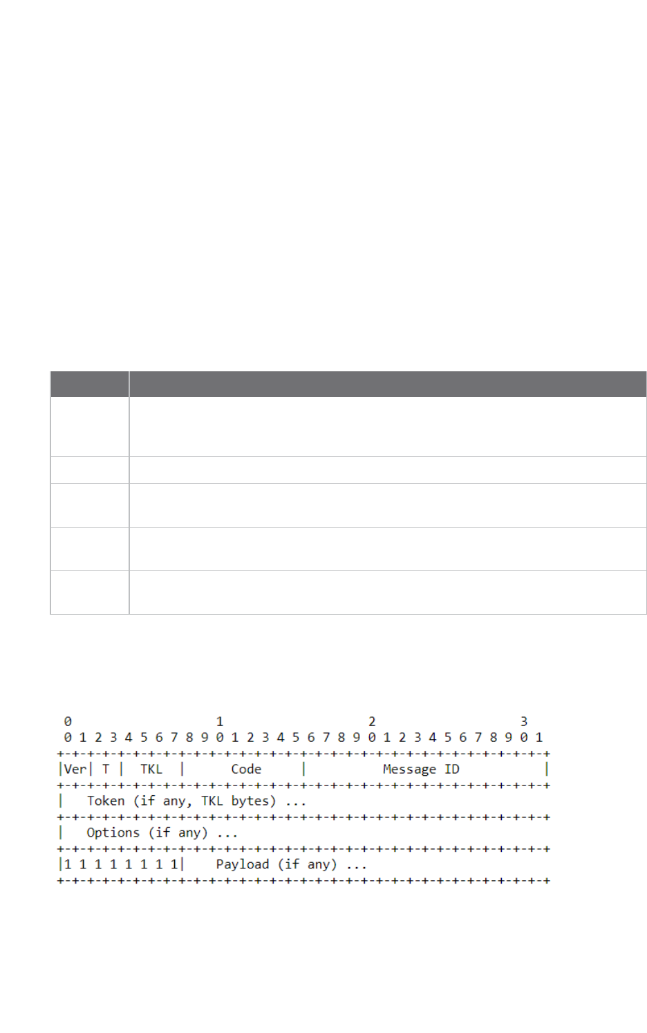
The following diagram shows the message format for the CoAP protocol; see ISSN: 2070-1721 for
details:
This is an example GET request:
44 01 C4 09 74 65 73 74 B7 65 78 61 6D 70 6C 65
Connection examples Get started with CoAP
Digi XBee3 Cellular LTE Cat 1 Smart Modem User Guide 33
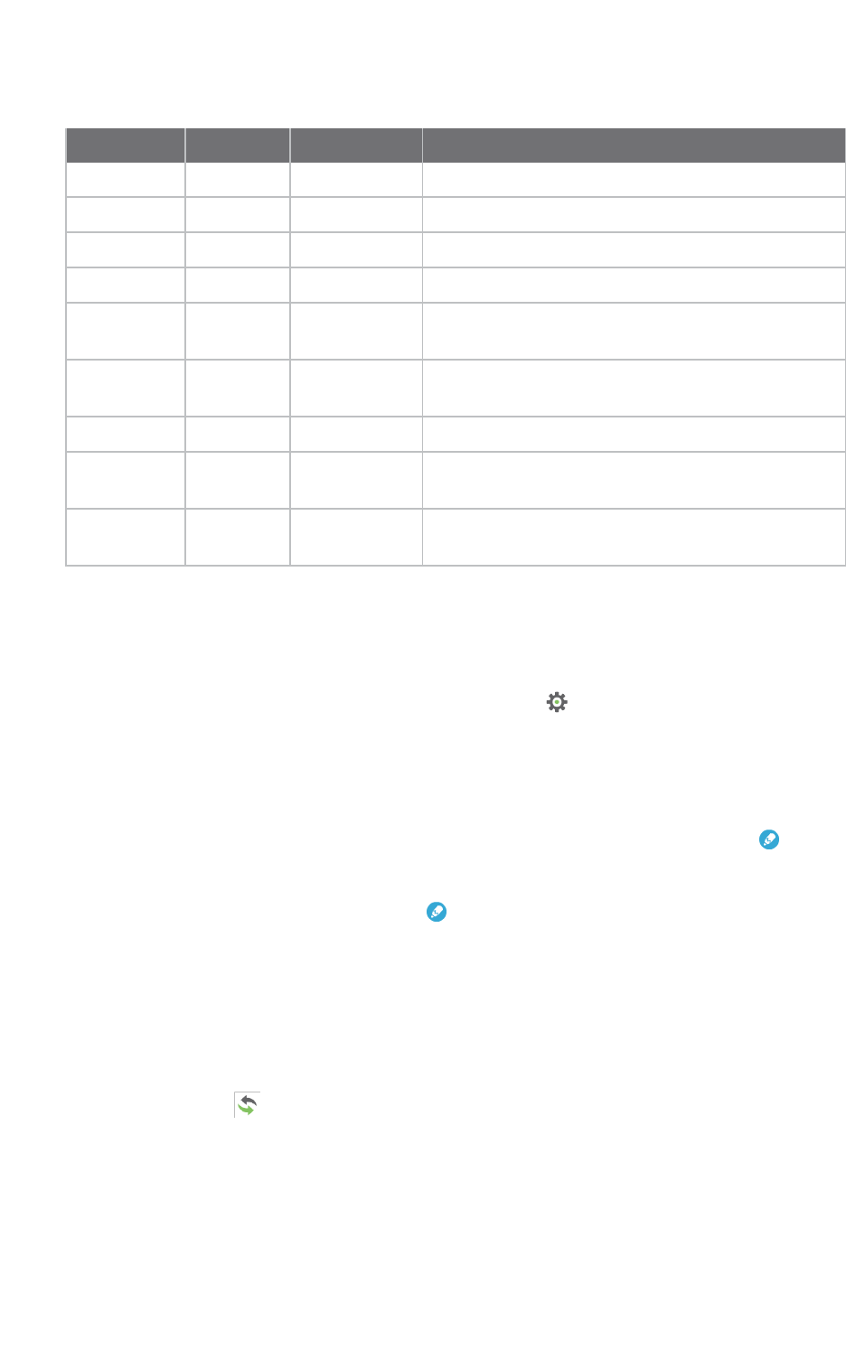
The following table describes the fields in the GETrequest.
Field HEX Bits Meaning
Ver 44 01 Version 01, which is mandatory here.
T 00 Type 0: confirmable.
TKL 0100 Token length: 4.
Code 01 000 00001 Code: 0.01, which indicates the GET method.
Message ID C4 09 2 Bytes equal
to hex at left
Message ID. The response message will have the
same ID. This can help out identification.
Token 74 65 73 74 4 Bytes equal
to hex at left
Token. The response message will have the same
token. This can help out identification.
Option delta B7 1011 Delta option: 11 indicates the option data is Uri-Path.
Optionlength 0111 Delta length: 7 indicates there are 7 bytes of data
following as a part of this delta option.
Option value 65 78 61 6D
70 6C 65
7 Bytes equal
to hex at left
Example.
Configure the device
1. Ensure that the device is set up correctly with the SIM card installed and the antennas
connected as described in Connect the hardware.
2. Open XCTU and click the Configuration working mode button.
3. Add the XBee Smart Modem to XCTU; see Add a device.
4. Select a device from the Radio Modules list. XCTU displays the current firmware settings for
that device.
5. To switch to UDPcommunication, in the IP field, select 0and click the Write button .
6. To set the target IP address that the XBee Smart Modem will talk to, in the DL field type
52.43.121.77and click the Write button . A CoAP server is publicly available at address
52.43.121.77.
7. To set the XBee Smart Modem to send data to port 5683 in decimal, in the DEfield, type 1633
and click the Write button.
8. To move into Transparent mode, in the APfield, select 0and click the Write button.
9. Wait for the AI (Association Indication) value to change to 0(Connected to the Internet). You
can click Read to get an update on the AI value.
Example: manually perform a CoAPrequest
Follow the steps in Configure the device prior to this example. This example performs the CoAP
GETrequest:

Connection examples Get started with CoAP
Digi XBee3 Cellular LTE Cat 1 Smart Modem User Guide 34
nMethod: GET
nURI: example
nGiven message token: test
1. Click the Consoles working mode button on the toolbar to add a customized packet.
2. From the AT console, click the Add new packet button in the Send packets dialog. The
Add new packet dialog appears.
3. Click the HEX tab and type the name of the data packet: GET_EXAMPLE.
4. Copy and past the following text into the HEX input tab:
44 01 C4 09 74 65 73 74 B7 65 78 61 6D 70 6C 65
This is the CoAP protocol message decomposed by bytes to perform a GET request on an
example URI with a token test.
5. Click Add packet.
6. Click the Open button .
7. Click Send selected packet. The message is sent to the public CoAP server configured in
Configure the device. A response appears in the Console log. Blue text is the query, red text is
the response.
The payload is Get to uri: example, which specifies that this is a successful CoAP GET to URI end
example, which was specified in the query.
Click the Close button to terminate the serial connection.
Example: use Python to generate a CoAP message
This example illustrates how the CoAP protocol can perform GET/POST/PUT/DELETE requests
similarly to the HTTP protocol and how to do this using the XBee Smart Modem. In this example, the
XBee Smart Modem talks to a CoAP Digi Server. You can use this client code to provide an abstract
wrapper to generate a CoAP message that commands the XBee Smart Modem to talk to the remote
CoAP server.
Note It is crucial to configure the XBee Smart Modem settings. See Configure the device and follow
the steps. You can target the IP address to a different CoAP public server.
1. Install Python 2.7. The Installation guide is located at: python.org/downloads/.
2. Download and install the CoAPthon library in the python environment from
pypi.python.org/pypi/CoAPthon.
3. Download these two .txt files: Coap.txt and CoapParser.txt. After you download them, open the
files in a text editor and save them as .py files.
4. In the folder that you place the Coap.py and CoapParser.py files, press Shift +right-click and
then click Open command window.
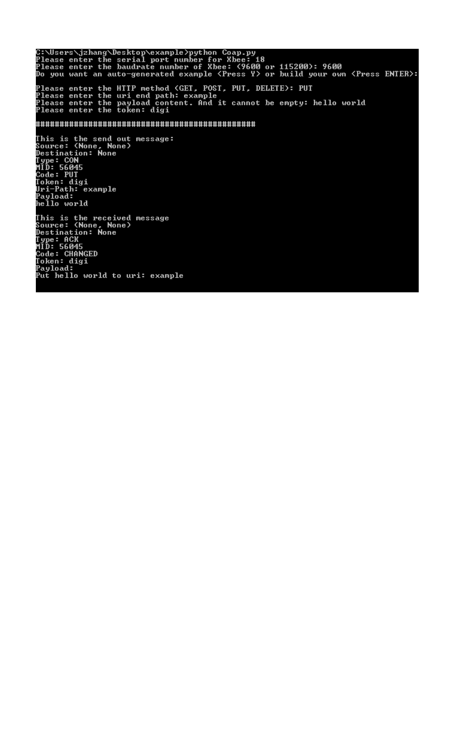
5. At the command prompt, type python Coap.py and press Enter to run the program.

Connection examples Get started with CoAP
Digi XBee3 Cellular LTE Cat 1 Smart Modem User Guide 35
6. Type the USB port number that the XBee Smart Modem is connected to and press Enter. Only
the port number is required, so if the port is COM19, type 19.
Note If you do not know the port number, open XCTU and look at the XBee Smart Modem in the Radio
Modules list. This view provides the port number and baud rate, as in the figure below where the baud
rate is 9600 b/s.
7. Type the baud rate and press Enter. You must match the device's current baud rate.
XCTUprovides the current baud rate in the BD Baud Rate field. In this example you would type
9600.
8. Press Yif you want an auto-generated example. Press Enter to build your own CoAP request.
9. If you press Yit generates a message with:
nMethod: POST
nURI: example
npayload:hello world
ntoken: test
The send and receive message must match the same token and message id. Otherwise, the client re-
attempts the connection by sending out the request.
In the following figure, the payload contains the server response to the query. It shows the results for
when you press Enter rather than Y.
Connection examples Get started with CoAP
Digi XBee3 Cellular LTE Cat 1 Smart Modem User Guide 36
Connection examples Connect to a TCP/IP address
Digi XBee3 Cellular LTE Cat 1 Smart Modem User Guide 37
Connect to a TCP/IP address
The XBee Smart Modem can send and receive TCP messages while in Transparent mode; see
Transparent operating mode.
Note You can use this example as a template for sending and receiving data to or from any
TCP/IPserver.
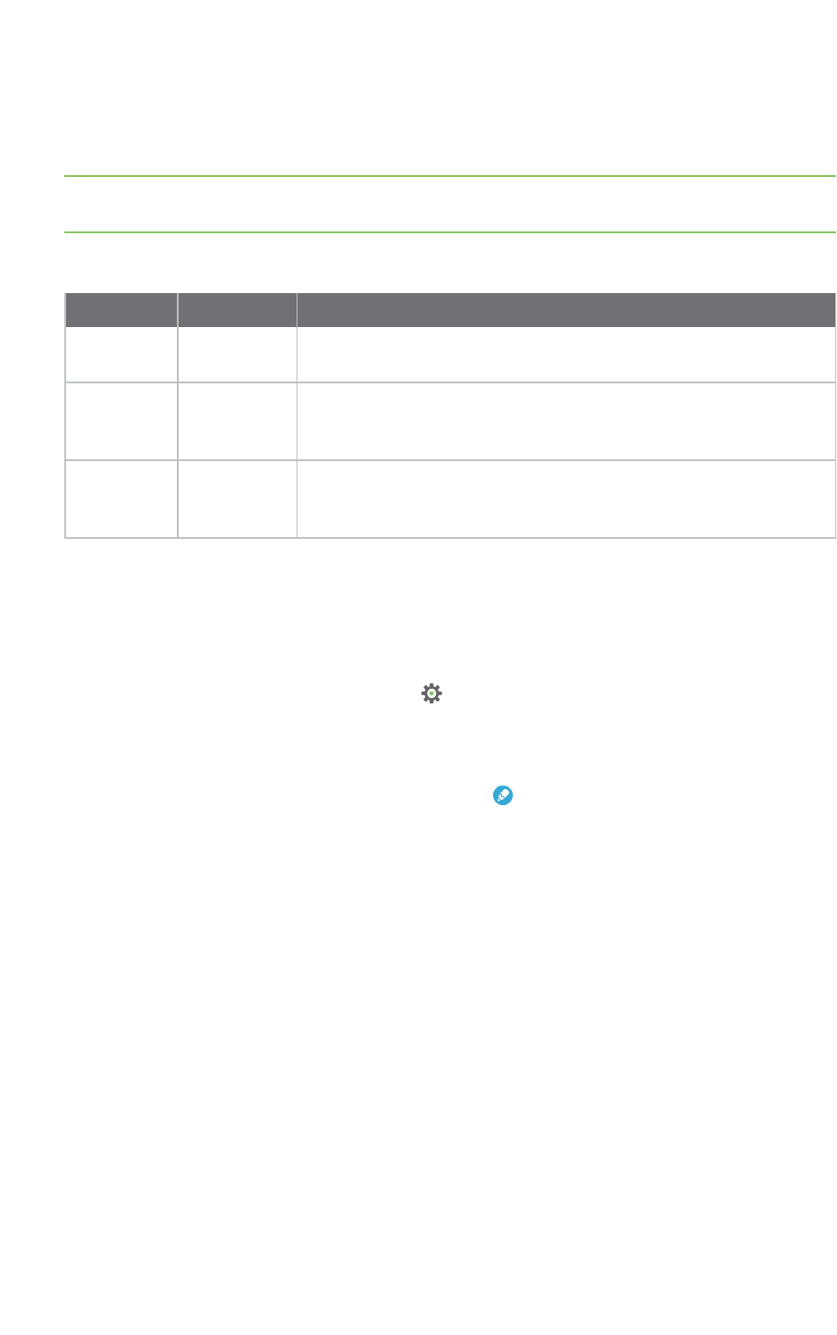
The following table explains the AT commands that you use in this example.
Command Value Description
IP (IP
Protocol)
1 Set the expected transmission mode to TCPcommunication.
DL
(Destination
IPAddress)
<Target
IPaddress>
The target IP address that you send and receive from. For example, a
data logging server’s IP address that you want to send
measurements to.
DE
(Destination
Port)
<Target
portnumber>
The target port number that the device sends the transmission to.
This is represented as a hexadecimal value.
To connect to a TCP/IP address:
1. Ensure that the device is set up correctly with the SIM card installed and the antennas
connected as described in Connect the hardware.
2. Open XCTU and Add a device.
3. Click the Configuration working mode button.
4. Select a device from the Radio Modules list. XCTU displays the current firmware settings for
that device.
5. In the IP field, select 1 and click the Write button .
6. In the DL field, type the <target IP address> and click the Write button. The target IP address
is the IPaddress that you send and receive from.
7. In the DE field, type the <target port number>, converted to hexadecimal, and click the Write
button.
8. Exit Command mode.
After exiting Command mode, any UART data sent to the device is sent to the destination IP address
and port number after the RO (Packetization Timeout) occurs.
Debugging
If you experience problems with the settings in this example, you can load the default settings in
XCTU:

Connection examples Connect to a TCP/IP address
Digi XBee3 Cellular LTE Cat 1 Smart Modem User Guide 38
1. On the Configuration toolbar, click the Default button to load the default values
established by the firmware, and click Yes to confirm.
2. Factory settings are loaded but not written to the device. To write them, click the Write button
on the toolbar.

Connection examples Get started with MQTT
Digi XBee3 Cellular LTE Cat 1 Smart Modem User Guide 39
Get started with MQTT
MQ Telemetry Transport (MQTT) is a messaging protocol that is ideal for the Internet of Things (IoT)
due to a light footprint and its use of the publish-subscribe model. In this model, a client connects to a
broker, a server machine responsible for receiving all messages, filtering them, and then sending
messages to the appropriate clients.
The first two MQTTexamples do not involve the XBee Smart Modem. They demonstrate using the
MQTTlibraries because those libraries are required for Use MQTT over the XBee Cellular Modem with
a PC.
The examples in this guide assume:
nSome knowledge of Python.
nAn integrated development environment (IDE)such as PyCharm, IDLE or something similar.
The examples require:
nAn XBee Smart Modem.
nA compatible development board, such as the XBIB-U.
nXCTU. See Configure the device using XCTU.
nThat you install Python on your computer. You can download Python from:
https://www.python.org/downloads/.
nThat you install the pyserial and paho-mqtt libraries to the Python environment. If you use
Python 2, install these libraries from the command line with pip install pyserial and pip
install paho-mqtt. If you use Python 3, use pip3 install pyserial and pip3 install paho-mqtt.
nThe full MQTT library source code, which includes examples and tests, which is available in the
paho-mqtt github repository at https://github.com/eclipse/paho.mqtt.python. To download this
repository you must have Git installed.
Example: MQTT connect
This example provides insight into the structure of packets in MQTT as well as the interaction
between the client and broker. MQTT uses different packets to accomplish tasks such as connecting,
subscribing, and publishing. You can use XCTU to perform a basic example of sending a broker a
connect packet and receiving the response from the server, without requiring any coding. This is a
good way to see how the client interacts with the broker and what a packet looks like. The following
table is an example connect packet:
Description Hex value
CONNECT packet fixed header
byte 1 Control packet type 0x10
byte 2 Remaining length 0x10
CONNECT packet variable header
Protocol name

Connection examples Get started with MQTT
Digi XBee3 Cellular LTE Cat 1 Smart Modem User Guide 40
Description Hex value
byte 1 Length MSB (0) 0x00
byte 2 Length LSB (4) 0x04
byte 3 (M) 0x4D
byte 4 (Q) 0x51
byte 5 (T) 0x54
byte 6 (T) 0x54
Protocol level
byte 7 Level (4) 0x04
Connect flags
byte 8 CONNECT flags byte, see the table below for the bits. 0X02
Keep alive
byte 9 Keep Alive MSB (0) 0X00
byte 10 Keep Alive LSB (60) 0X3C
Client ID
byte 11 Length MSB (0) 0x00
byte 12 Length LSB (4) 0x04
byte 13 (D) 0x44
byte 14 (I) 0x49
byte 15 (G) 0x47
byte 16 (I) 0x49
The following table describes the fields in the packet:
Fieldname Description
ProtocolName The connect packet starts with the protocol name, which is MQTT. The length of
the protocol name (in bytes) is immediately before the name itself.
ProtocolLevel Refers to the version of MQTT in use, in this case a value of 4 indicates MQTT
version 3.1.1.
Connect Flags Indicate certain aspects of the packet. For simplicity, this example only sets the
Clean Session flag, which indicates to the client and broker to discard any previous
session and start a new one.
Keep Alive How often the client pings the broker to keep the connection alive; in this example
it is set to 60 seconds.
Connection examples Get started with MQTT
Digi XBee3 Cellular LTE Cat 1 Smart Modem User Guide 41
Fieldname Description
Client ID The length of the ID (in bytes) precedes the ID itself. Each client connecting to a
broker must have a unique client ID. In the example, the ID is DIGI. When using the
Paho MQTT Python libraries, a random alphanumeric ID is generated if you do not
specify an ID.
The following table provides the CONNECT flag bits from byte 8, the CONNECT flags byte.
CONNECT Flag Bit(s) Bit 7 Bit 6 Bit 5 Bit 4 Bit 3 Bit 2 Bit 1 Bit 0
User name flag 0
Password flag 0
Will retain 0
Will QoS 0 0
Will flag 0
Clean session 1
Reserved 0
Send a connect packet
Now that you know what a connect packet looks like, you can send a connect packet to a broker and
view the response. Open XCTU and click the Configuration working mode button.
1. Ensure that the device is set up correctly with the SIM card installed and the antennas
connected as described in Connect the hardware.
2. Open XCTU and click the Configuration working mode button.
3. Add the XBee Smart Modem to XCTU; see Add a device.
4. Select a device from the Radio Modules list. XCTU displays the current firmware settings for
that device.
5. In the APfield, set Transparent Mode to [0] if it is not already and click the Write button.
6. In the DL field, type the IP address of the broker you wish to use. This example uses
198.41.30.241, which is the IP address for m2m.eclipse.org, a public MQTT broker.
7. In the DE field, type 75B and set the port that the broker uses. This example uses 75B, because
the default MQTT port is 1883 (0x75B).
8. Once you have entered the required values, click the Write button to write the changes to the
XBee Smart Modem.
9. Click the Consoles working mode button on the toolbar to open a serial console to the
device. For instructions on using the Console, see the AT console topic in the XCTU User Guide.
10. Click the Open button to open a serial connection to the device.
Connection examples Get started with MQTT
Digi XBee3 Cellular LTE Cat 1 Smart Modem User Guide 42
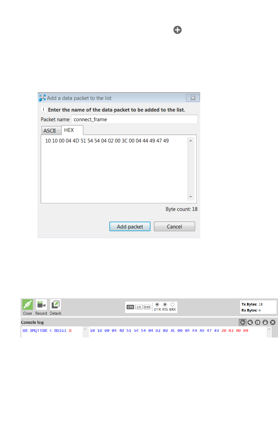
11. From the AT console, click the Add new packet button in the Send packets dialog. The
Add new packet dialog appears.
12. Enter the name of the data packet. Name the packet connect_frame or something similar.
13. Click the HEX input tab and type the following (these values are the same values from the
table in Example: MQTT connect):
10 10 00 04 4D 51 54 54 04 02 00 3C 00 04 44 49 47 49
14. Click Add packet. The new packet appears in the Send packets list.
15. Click the packet in the Send packets list.
16. Click Send selected packet.
17. A CONNACK packet response from the broker appears in the Console log. This is a connection
acknowledgment; a successful response should look like this:
You can verify the response from the broker as a CONNACK by comparing it to the structure of a
CONNACK packet in the MQTT documentation, which is available at http://docs.oasis-
open.org/mqtt/mqtt/v3.1.1/os/mqtt-v3.1.1-os.html#_Toc398718081).
Example: send messages (publish) with MQTT
A basic Python example of a node publishing (sending) a message is:

Connection examples Get started with MQTT
Digi XBee3 Cellular LTE Cat 1 Smart Modem User Guide 43
mqttc = mqtt.Client("digitest") # Create instance of client with client ID
“digitest”
mqttc.connect("m2m.eclipse.org", 1883) # Connect to (broker, port,
keepalive-time)
mqttc.loop_start() # Start networking daemon
mqttc.publish("digitest/test1", "Hello, World!") # Publish message to
“digitest /test1” topic
mqttc.loop_stop() # Kill networking daemon
Note You can easily copy and paste code from the online version of this guide. Use caution with the
PDF version, as it may not maintain essential indentations.
This example imports the MQTT library, allowing you to use the MQTT protocol via APIs in the library,
such as the connect(),subscribe(), and publish() methods.
The second line creates an instance of the client, named mqttc. The client ID is the argument you
passed in: digitest (this is optional).
In line 3, the client connects to a public broker, in this case m2m.eclipse.org, on port 1883 (the default
MQTT port, or 8883 for MQTT over SSL). There are many publicly available brokers available, you can
find a list of them here: https://github.com/mqtt/mqtt.github.io/wiki/brokers.
Line 4 starts the networking daemon with client.loop_start() to handle the background
network/data tasks.
Finally, the client publishes its message Hello, World! to the broker under the topic
digitest/backlog/test1. Any nodes (devices, phones, computers, even microcontrollers) subscribed to
that same topic on the same broker receive the message.
Once no more messages need to be published, the last line stops the network daemon with
client.loop_stop().
Example: receive messages (subscribe) with MQTT
This example describes how a client would receive messages from within a specific topic on the
broker:
import paho.mqtt.client as mqtt
def on_connect(client, userdata, flags, rc): # The callback for when the
client connects to the broker
print("Connected with result code {0}".format(str(rc))) # Print result
of connection attempt
client.subscribe("digitest/test1") # Subscribe to the topic
“digitest/test1”, receive any messages published on it
def on_message(client, userdata, msg): # The callback for when a PUBLISH
message is received from the server.
print("Message received-> " + msg.topic + " " + str(msg.payload)) #
Print a received msg
client = mqtt.Client("digi_mqtt_test") # Create instance of client with
client ID “digi_mqtt_test”
client.on_connect = on_connect # Define callback function for successful
connection
client.on_message = on_message # Define callback function for receipt of a

Connection examples Get started with MQTT
Digi XBee3 Cellular LTE Cat 1 Smart Modem User Guide 44
message
# client.connect("m2m.eclipse.org", 1883, 60) # Connect to (broker, port,
keepalive-time)
client.connect('127.0.0.1', 17300)
client.loop_forever() # Start networking daemon
Note You can easily copy and paste code from the online version of this guide. Use caution with the
PDF version, as it may not maintain essential indentations.
The first line imports the library functions for MQTT.
The functions on_connect and on_message are callback functions which are automatically called by
the client upon connection to the broker and upon receiving a message, respectively.
The on_connect function prints the result of the connection attempt, and performs the subscription.
It is wise to do this in the callback function as it guarantees the attempt to subscribe happens only
after the client is connected to the broker.
The on_message function prints the received message when it comes in, as well as the topic it was
published under.
In the body of the code, we:
nInstantiate a client object with the client ID digi_mqtt_test.
nDefine the callback functions to use upon connection and upon message receipt.
nConnect to an MQTT broker at m2m.eclipse.org, on port 1883 (the default MQTT port, or 8883
for MQTT over SSL) with a keepalive of 60 seconds (this is how often the client pings the broker
to keep the connection alive).
The last line starts a network daemon that runs in the background and handles data transactions and
messages, as well as keeping the socket open, until the script ends.
Use MQTT over the XBee Cellular Modem with a PC
To use this MQTT library over an XBee Smart Modem, you need a basic proxy that transfers a payload
received via the MQTT client’s socket to the serial or COM port that the XBee Smart Modem is active
on, as well as the reverse; transfer of a payload received on the XBee Smart Modem’s serial or COM
port to the socket of the MQTT client. This is simplest with the XBee Smart Modem in Transparent
mode, as it does not require code to parse or create API frames, and not using API frames means
there is no need for them to be queued for processing.
1. To put the XBee Cellular Modem in Transparent mode, set AP to 0.
2. Set DL to the IP address of the broker you want to use.
3. Set DE to the port to use, the default is 1883 (0x75B). This sets the XBee Smart Modem to
communicate directly with the broker, and can be performed in XCTU as described in Example:
MQTT connect.
4. You can make the proxy with a dual-threaded Python script, a simple version follows:
import threading
import serial
import socket
def setup():

Connection examples Get started with MQTT
Digi XBee3 Cellular LTE Cat 1 Smart Modem User Guide 45
"""
This function sets up the variables needed, including the serial port,
and it's speed/port settings, listening socket, and localhost adddress.
"""
global clisock, cliaddr, svrsock, ser
# Change this to the COM port your XBee Cellular module is using. On
# Linux, this will be /dev/ttyUSB#
comport = 'COM44'
# This is the default serial communication speed of the XBee Cellular
# module
comspeed = 115200
buffer_size = 4096 # Default receive size in bytes
debug_on = 0 # Enables printing of debug messages
toval = None # Timeout value for serial port below
# Serial port object for XBCell modem
ser = serial.Serial(comport,comspeed,timeout=toval)
# Listening socket (accepts incoming connection)
svrsock = socket.socket(socket.AF_INET,socket.SOCK_STREAM)
# Allow address reuse on socket (eliminates some restart errors)
svrsock.setsockopt(socket.SOL_SOCKET, socket.SO_REUSEADDR, 1)
clisock = None
cliaddr = None # These are first defined before thread creation
addrtuple = ('127.0.0.1', 17300) # Address tuple for localhost
# Binds server socket to localhost (allows client program connection)
svrsock.bind(addrtuple)
svrsock.listen(1) # Allow (1) connection
def ComReaderThread():
"""
This thread listens on the defined serial port object ('ser') for data
from the modem, and upon receipt, sends it out to the client over the
client socket ('clisock').
"""
global clisock
while (1):
resp = ser.read() ## Read any available data from serial port
print("Received {} bytes from modem.".format(len(resp)))
clisock.sendall(resp) # Send RXd data out on client socket
print("Sent {} byte payload out socket to client.".format(len
(resp)))
def SockReaderThread():
"""
This thread listens to the MQTT client's socket and upon receiving a
payload, it sends this data out on the defined serial port ('ser') to
the
modem for transmission.
"""
global clisock
while (1):
data = clisock.recv(4096) # RX data from client socket
# If the RECV call returns 0 bytes, the socket has closed
if (len(data) == 0):
print("ERROR - socket has closed. Exiting socket reader
thread.")

Connection examples Get started with MQTT
Digi XBee3 Cellular LTE Cat 1 Smart Modem User Guide 46
return 1 # Exit the thread to avoid a loop of 0-byte receptions
else:
print("Received {} bytes from client via socket.".format(len
(data)))
print("Sending payload to modem...")
bytes_wr = ser.write(data) # Write payload to modem via
UART/serial
print("Wrote {} bytes to modem".format(bytes_wr))
def main():
setup() # Setup the serial port and socket
global clisock, svrsock
if (not clisock): # Accept a connection on 'svrsock' to open 'clisock'
print("Awaiting ACCEPT on server sock...")
(clisock,cliaddr) = svrsock.accept() # Accept an incoming
connection
print("Connection accepted on socket")
# Make thread for ComReader
comthread = threading.Thread(target=ComReaderThread)
comthread.start() # Start the thread
# Make thread for SockReader
sockthread = threading.Thread(target=SockReaderThread)
sockthread.start() # Start the thread
main()
Note This script is a general TCP-UART proxy, and can be used for other applications or scripts that
use the TCP protocol. Its functionality is not limited to MQTT.
Note You can easily copy and paste code from the online version of this guide. Use caution with the
PDF version, as it may not maintain essential indentations.
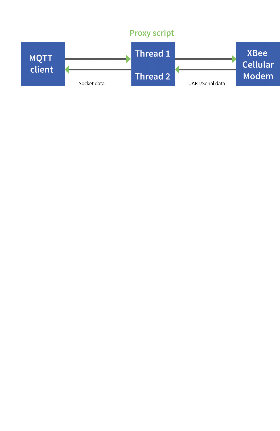
This proxy script waits for an incoming connection on localhost (127.0.0.1), on port 17300. After
accepting a connection, and creating a socket for that connection (clisock), it creates two threads,
one that reads the serial or COM port that the XBee Smart Modem is connected to, and one that
reads the socket (clisock), that the MQTT client is connected to.
With:
nThe proxy script running
nThe MQTT client connected to the proxy script via localhost (127.0.0.1)
nThe XBee Smart Modem connected to the machine via USB and properly powered
nAP,DL, and DE set correctly
the proxy acts as an intermediary between the MQTT client and the XBee Smart Modem, allowing the
MQTT client to use the data connection provided by the device.
Think of the proxy script as a translator between the MQTT client and the XBee Smart Modem. The
following figure shows the basic operation.
Connection examples Software libraries
Digi XBee3 Cellular LTE Cat 1 Smart Modem User Guide 47
The thread that reads the serial port forwards any data received onward to the client socket, and the
thread reading the client socket forwards any data received onward to the serial port. This is
represented in the figure above.
The proxy script needs to be running before running an MQTT publish or subscribe script.
1. With the proxy script running, run the subscribe example from Example: receive messages
(subscribe) with MQTT, but change the connect line from client.connect("m2m.eclipse.org",
1883, 60) to client.connect("127.0.0.1", port=17300, keepalive=20). This connects the
MQTT client to the proxy script, which in turn connects to a broker via the XBee Smart
Modem’s internet connection.
2. Run the publish example from Example: send messages (publish) with MQTT in a third Python
instance (while the publish script is running you will have three Python scripts running at the
same time).
The publish script runs over your computer’s normal Internet connection, and does not use the XBee
Smart Modem. You are able to see your published message appear in the subscribe script’s output
once it is received from the broker via the XBee Smart Modem. If you watch the output of the proxy
script during this process you can see the receptions and transmissions taking place.
The proxy script must be running before you run the subscribe and publish scripts. If you stop the
subscribe script, the socket closes, and the proxy script shows an error. If you try to start the proxy
script after starting the subscribe script, you may also see a socket error. To avoid these errors, it is
best to start the scripts in the correct order: proxy, then subscribe, then publish.
Software libraries
One way to communicate with the XBee device is by using a software library. The libraries available
for use with the XBee Smart Modem include:
nXBee Java library
nXBee Python library
The XBee Java Library is a Java API. The package includes the XBee library, its source code and a
collection of samples that help you develop Java applications to communicate with your XBee devices.
The XBee Python Library is a Python API that dramatically reduces the time to market of XBee
projects developed in Python and facilitates the development of these types of applications, making it
an easy process.

Get started with MicroPython
This guide provides an overview of how to use MicroPython with the XBee Smart Modem. For in-depth
information and more complex code examples, refer to the Digi MicroPython Programming Guide.
Continue with this guide for simple examples to get started using MicroPython on the XBee Smart
Modem.
About MicroPython
MicroPython is an open-source programming language based on Python 3, with much of the same
syntax and functionality, but modified to fit on small devices with limited hardware resources, such as
microcontrollers, or in this case, a cellular modem.
Why use MicroPython
MicroPython enables on-board intelligence for simple sensor or actuator applications using digital and
analog I/O. MicroPython can help manage battery life. Cryptic readings can be transformed into useful
data, excess transmissions can be intelligently filtered out, modern sensors and actuators can be
employed directly, and logic can glue inputs and outputs together in an intelligent way.
For more information about MicroPython, see www.micropython.org.
For more information about Python, see www.python.org.
MicroPython on the XBee Smart Modem
The XBee Smart Modem has MicroPython running on the device itself. You can access a MicroPython
prompt from the XBee Smart Modem when you install it in an appropriate development board (XBDB
or XBIB), and connect it to a computer via a USB cable.
Note MicroPython does not work with SPI.
The examples in this guide assume:
nYou have XCTU on your computer. See Configure the device using XCTU.
nYou have a terminal program installed on your computer. We recommend using the Use the
MicroPython Terminal in XCTU. This requires XCTU 6.3.7 or higher.
nYou have an XBee Smart Modem installed in an appropriate development board such as an
XBIB-U-DEV or an XBIB-2.
Note Most examples in this guide require the XBIB-U-DEV board.
Digi XBee3 Cellular LTE Cat 1 Smart Modem User Guide 48

Get started with MicroPython Use XCTU to enter the MicroPython environment
Digi XBee3 Cellular LTE Cat 1 Smart Modem User Guide 49
nThe XBee Smart Modem is connected to the computer via a USB cable and XCTU recognizes it.
nThe board is powered by an appropriate power supply, 12 VDC and at least 1.1 A.
Use XCTU to enter the MicroPython environment
To use the XBee Smart Modem in the MicroPython environment:
1. Use XCTU to add the device(s); see Configure the device using XCTU and Add a device.
2. The XBee Smart Modem appears as a box in the Radio Modules information panel. Each
module displays identifying information about itself.
3. Click this box to select the device and load its current settings.
4. To set the device's baud rate to 115200 b/s, in the BD field select 115200 [7] or higher and
click the Write button . We recommend using flow control to avoid data loss, especially
when pasting large amounts of code/text.
5. To put the XBee Smart Modem into MicroPython mode, in the APfield select MicroPython
REPL [4] and click the Write button .
6. Note what COM port(s) the XBee Smart Modem is using, because you will need this information
when you use terminal communication. The Radio Modules information panel lists the COM
port in use.
Use the MicroPython Terminal in XCTU
You can use the MicroPython Terminal to communicate with the XBee Smart Modem when it is in
MicroPython mode.1This requires XCTU 6.3.7 or higher. To enter MicroPython mode, follow the steps
in Use XCTU to enter the MicroPython environment. To use the MicroPython Terminal:
1. Click the Tools drop-down menu and select MicroPython Terminal. The terminal opens.
2. Click Open. If you have not already added devices to XCTU:
a. In the Select the Serial/USB port area, click the COM port that the device uses.
b. Verify that the baud rate and other settings are correct.
3. Click OK. The Open icon changes to Close , indicating that the device is properly connected.
4. Press Ctrl+Bto get the MicroPython version banner and prompt.
You can now type or paste MicroPython commands at the >>> prompt.
Troubleshooting
If you receive No such port: 'Port is already in use by other applications.' in the MicroPython
Terminal close any other console sessions open inside XCTU and close any other serial terminal
programs connected to the device, then retry the MicroPython connection in XCTU.
If the device seems unresponsive, try pressing Ctrl+C to end any running programs.
1See Other terminal programs if you do not use the MicroPython Terminal in XCTU.
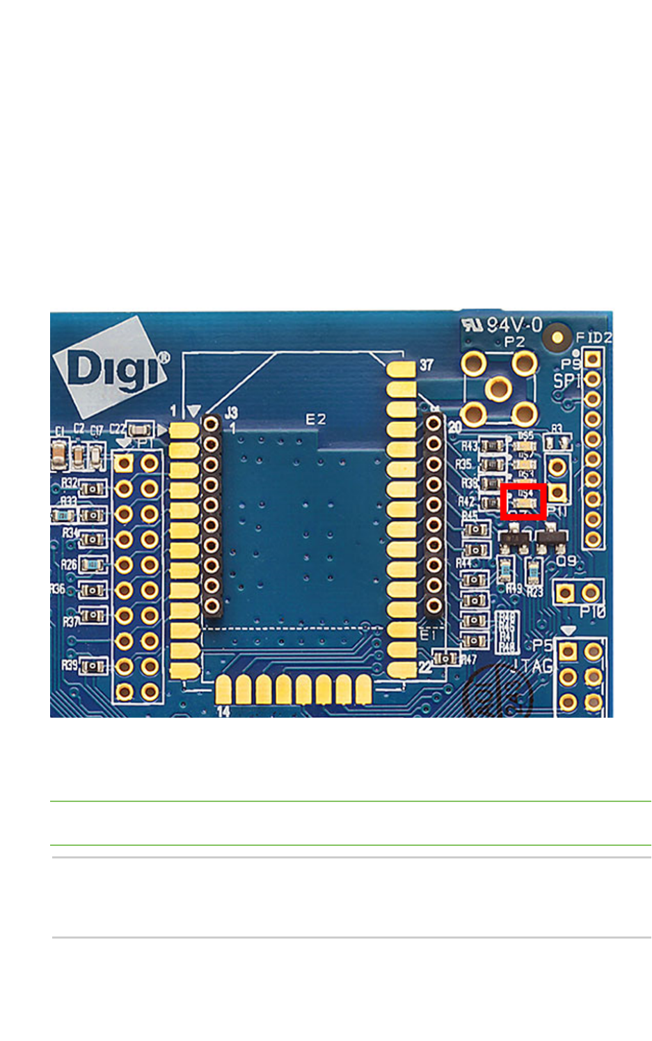
Get started with MicroPython Example: hello world
Digi XBee3 Cellular LTE Cat 1 Smart Modem User Guide 50
You can use the +++ escape sequence and look for an OK for confirmation that you have the correct
baud rate.
Example: hello world
1. At the MicroPython >>> prompt, type the Python command: print("Hello, World!")
2. Press Enter to execute the command. The terminal echos back Hello, World!.
Example: turn on an LED
1. Note the DS4 LED on the XBIB board. The following image highlights it in a red box. The LED is
normally off.
2. At the MicroPython >>> prompt, type the commands below, pressing Enter after each one.
After entering the last line of code, the LED illuminates. Anything after a #symbol is a
comment, and you do not need to type it.
Note You can easily copy and paste code from the online version of this guide. Use caution with the
PDF version, as it may not maintain essential indentations.
import machine
from machine import Pin
led = Pin("D4", Pin.OUT, value=0) # Makes a pin object set to output 0.
# One might expect 0 to mean OFF and 1 to mean ON, and this is normally the
case.

Get started with MicroPython Example: code a request help button
Digi XBee3 Cellular LTE Cat 1 Smart Modem User Guide 51
# But the LED we are turning on and off is setup as what is# known as
"active low".
# This means setting the pin to 0 allows current to flow through the LED and
then through the pin, to ground.
3. To turn it off, type the following and press Enter:
led.value(1)
You have successfully controlled an LED on the board using basic I/O.
Example: code a request help button
This example provides a fast, deep dive into MicroPython designed to let you see some of the powerful
things it can do with minimal code. It is not meant as a tutorial; for in-depth examples refer to the Digi
MicroPython Programming Guide.
Many stores have help buttons in their aisles that a customer can press to alert the store staff that
assistance is required in that aisle. You can implement this type of system using the Digi XBee Smart
Modem, and this example provides the building blocks for such a system. This example, based on SMS
paging, can have many other uses such as alerting someone with a text to their phone if a water
sensor in a building detects water on the floor, or if a temperature sensor reports a value that is too
hot or cold relative to normal operation.
Enter MicroPython paste mode
In the following examples it is helpful to know that MicroPython supports paste mode, where you can
copy a large block of code from this user guide and paste it instead of typing it character by character.
To use paste mode:
1. Copy the code you want to run. For example, copy the following code that is the code from the
LED example:
from machine import Pin
led = Pin("D4", Pin.OUT, value=0)
Note You can easily copy and paste code from the online version of this guide. Use caution with the
PDF version, as it may not maintain essential indentations.
2. In the terminal, at the MicroPython >>> prompt type Ctrl+Eto enter paste mode. The terminal
displays paste mode; Ctrl-C to cancel, Ctrl-D to finish.
3. The code appears in the terminal occupying four lines, each line starts with its line number and
three =symbols. For example line 1 starts with 1===.
4. If the code is correct, press Ctrl+Dto run the code and you should once again see the DS4 LED
turn on. If you get a Line 1 SyntaxError: invalid syntax error, see Syntax error at line 1.
If you wish to exit paste mode without running the code, for example, or if the code did not
copy correctly, press Ctrl+Cto cancel and return to the normal MicroPython >>> prompt.
5. Next turn the LED off. Copy the code below:
from machine import Pin
led = Pin("D4", Pin.OUT, value=1)
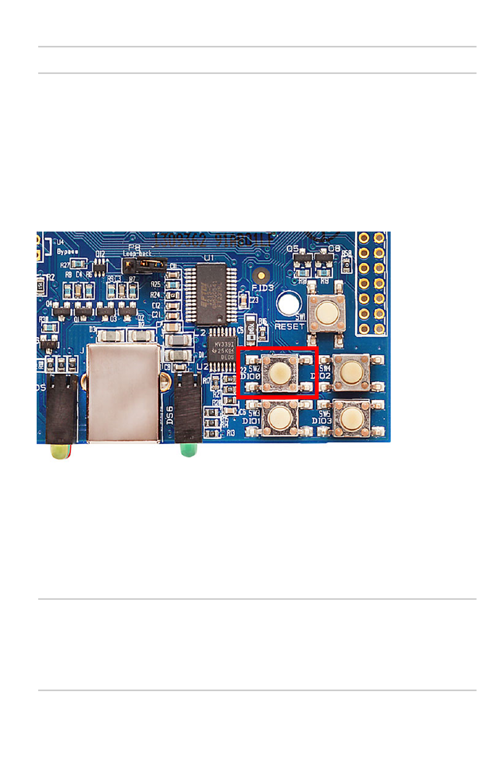
Get started with MicroPython Example: code a request help button
Digi XBee3 Cellular LTE Cat 1 Smart Modem User Guide 52
print("DS4 LED now OFF!")
print("Paste Mode Successful!")
6. Press Ctrl+Eto enter paste mode.
7. Press Ctrl +Shift +Vor right-click in the Terminal and select Paste to paste the copied code.
8. If the code is correct, press Ctrl+Dto run it. The LED should turn off and you should see two
confirmation messages print to the screen.
Catch a button press
For this part of the example, you write code that responds to a button press on the XBIB-U-DEV board
that comes with the XBee Smart Modem Development Kit. The code monitors the pin connected to
the button on the board labeled SW2.
On the board you see DIO0 written below SW2, to the left of the button. This represents the pin that
the button is connected to.
In MicroPython, you will create a pin object for the pin that is connected to the SW2 button. When you
create the pin object, the DIO0 pin is called D0 for short.
The loop continuously checks the value on that pin and once it goes to 0(meaning the button has been
pressed) a print() call prints the message Button pressed! to the screen.
At the MicroPython >>> prompt, copy the following code and enter it into MicroPython using paste
mode (Ctrl+E), right-click in the Terminal, select Paste to paste the copied code, and press Ctrl+Dto
run the code.
# Import the Pin module from machine, for simpler syntax.
from machine import Pin
# Create a pin object for the pin that the button "SW2" is connected to.
dio0 = Pin("D0", Pin.IN, Pin.PULL_UP)
# Give feedback to inform user a button press is needed.
print("Waiting for SW2 press...")

Get started with MicroPython Example: code a request help button
Digi XBee3 Cellular LTE Cat 1 Smart Modem User Guide 53
# Create a WHILE loop that checks for a button press.
while (True):
if (dio0.value() == 0): # Once pressed.
print("Button pressed!") # Print message once pressed.
break # Exit the WHILE loop.
# When you press SW2, you should see "Button pressed!" printed to the
screen.
# You have successfully performed an action in response to a button press!
Note You can easily copy and paste code from the online version of this guide. Use caution with the
PDF version, as it may not maintain essential indentations.
Note If you have problems pasting the code, see Syntax error at line 1. For SMS failures, see Error
Failed to send SMS.
Send a text (SMS) when the button is pressed
After creating a while loop that checks for a button press, add sending an SMS to your code. Instead of
printing Button pressed! to the screen, this code sends Button pressed to a cell phone as a text
(SMS) message.
To accomplish this, use the sms_send() method, which sends a string to a given phone number. It
takes the arguments in the following order:
1. <phone number>
2. <message-to-be-sent>
Before you run this part of the example, you must create a variable that holds the phone number of
the cell phone or mobile device you want to receive the SMS.
1. To do this, at the MicroPython >>> prompt, type the following command, replacing 1123456789
with the full phone number (no dashes, spaces, or other symbols) and press Enter:
ph = 1123456789
2. After you create this ph variable with your phone number, copy the code below and enter it
into MicroPython using paste mode (Ctrl+E) and then run it.
from machine import Pin
import network # Import network module
import time
c = network.Cellular() # initialize cellular network parameter
dio0 = Pin("D0", Pin.IN, Pin.PULL_UP)
while not c.isconnected(): # While no network connection.
print("Waiting for connection to cell network...")
time.sleep(5)
print("Connected.")
# Give feedback to inform user a button press is needed.
print("Waiting for SW2 press...")
while (True):
if (dio0.value() == 0):
# When SW2 is pressed, the module will send an SMS
# message saying "Button pressed" to the given target cell phone

Get started with MicroPython Example: code a request help button
Digi XBee3 Cellular LTE Cat 1 Smart Modem User Guide 54
number.
try:
c.sms_send(ph, 'Button Pressed')
print("Sent SMS successfully.")
except OSError:
print("ERROR- failed to send SMS.")
# Exit the WHILE loop.
break
Note You can easily copy and paste code from the online version of this guide. Use caution with the
PDF version, as it may not maintain essential indentations.
Note If you have problems pasting the code, see Syntax error at line 1. For SMS failures, see Error
Failed to send SMS.
Add the time the button was pressed
After you add the ability to send an SMS to the code, add functionality to insert the time at which the
button was pressed into the SMS that is sent. To accomplish this:
1. Create a UDP socket with the socket() method.
2. Save the IP address and port of the time server in the addr variable.
3. Connect to the time server with the connect() method.
4. Send hello to the server to prompt it to respond with the current date and time.
5. Receive and store the date/time response in the buf variable.
6. Send an SMSin the same manner as before using the sms_send() method, except that you add
the time into the SMS message, such that the message reads: [Button pressed at: YYYY-MM-
DD HH:MM:SS]
To verify that your phone number is still in the memory, at the MicroPython >>> prompt, type ph and
press Enter.
If MicroPython responds with your number, copy the following code and enter it into MicroPython
using paste mode and then run it. If it returns an error, enter your number again as shown in Send a
text (SMS) when the button is pressed. With your phone number in memory in the ph variable, copy
the code below and enter it into MicroPython using paste mode (Ctrl+E) and then run it.
from machine import Pin
import network
import usocket
import time
c = network.Cellular()
dio0 = Pin("D0", Pin.IN, Pin.PULL_UP)
while not c.isconnected(): # While no network connection.
print("Waiting for connection to cell network...")
time.sleep(5)
print("Connected.")
# Give feedback to inform user a button press is needed.
print("Waiting for SW2 press...")
while (1):
if (dio0.value() == 0):
Get started with MicroPython Exit MicroPython mode
Digi XBee3 Cellular LTE Cat 1 Smart Modem User Guide 55
# When button pressed, now the module will send "Button Press" AND
# the time at which it was pressed in an SMS message to the given
# target cell phone number.
socketObject = usocket.socket(usocket.AF_INET, usocket.SOCK_DGRAM)
# Connect the socket object to the web server specified in
"address".
addr = ("52.43.121.77", 10002)
socketObject.connect(addr)
bytessent = socketObject.send("hello")
print("Sent %d bytes on socket" % bytessent)
buf = socketObject.recv(1024)
# Send message to the given number. Handle error if it occurs.
try:
c.sms_send(ph, 'Button Pressed at: ' + str(buf))
print("Sent SMS successfully.")
except OSError:
print("ERROR- failed to send SMS.")
# Exit the WHILE loop.
break
Note You can easily copy and paste code from the online version of this guide. Use caution with the
PDF version, as it may not maintain essential indentations.
Now you have a system based on the XBee Smart Modem that sends an SMS in response to a certain
input, in this case a simple button press.
Note If you have problems pasting the code, see Syntax error at line 1. For SMS failures, see Error
Failed to send SMS.
Exit MicroPython mode
To exit MicroPython mode:
1. In the XCTU MicroPython Terminal, click the green Close button .
2. Click Close at the bottom of the terminal to exit the terminal.
3. In XCTU's Configuration working mode , change AP API Enable to another mode and click
the Write button . We recommend changing to Transparent mode [0], as most of the
examples use this mode.
Other terminal programs
If you do not use the MicroPython Terminal in XCTU, you can use other terminal programs to
communicate with the XBee Smart Modem. If you use Microsoft Windows, follow the instructions for
Tera Term, if you use Linux, follow the instructions for picocom. To download these programs:
nTera Term for Windows; see https://ttssh2.osdn.jp/index.html.en.
nPicocom for Linux; see https://developer.ridgerun.com/wiki/index.php/Setting_up_Picocom_-_
Ubuntu and for the source code and in-depth information https://github.com/npat-
efault/picocom.
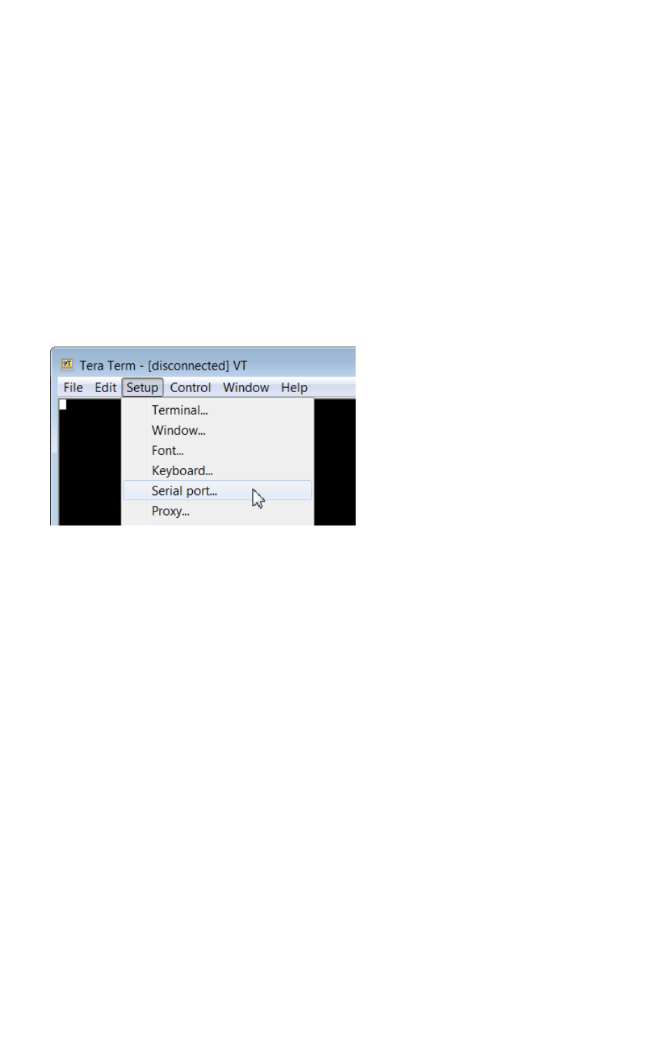
Get started with MicroPython Other terminal programs
Digi XBee3 Cellular LTE Cat 1 Smart Modem User Guide 56
Tera Term for Windows
With the XBee Smart Modem in MicroPython mode (AP =4), you can access the MicroPython prompt
using a terminal.
1. Open Tera Term. The Tera Term: New connection window appears.
2. Click the Serial radio button to select a serial connection.
3. From the Port: drop-down menu, select the COM port that the XBee Smart Modem is
connected to.
4. Click OK. The COMxx - Tera Term VT terminal window appears and Tera Term attempts to
connect to the device at a baud rate of 9600 b/s. The terminal will not allow communication
with the device since the baud rate setting is incorrect. You must change this rate as it was
previously set to 115200 b/s.
5. Click Setup and Serial Port. The Tera Term: Serial port setup window appears.
6. In the Tera Term: Serial port setup window, set the parameters to the following values:
nPort: Shows the port that the XBee Smart Modem is connected on.
nBaud rate:115200
nData: 8 bit
nParity: none
nStop: 1 bit
nFlow control: hardware
nTransmit delay: N/A
7. Click OK to apply the changes to the serial port settings. The settings should go into effect
right away.
8. To verify that local echo is not enabled and that extra line-feeds are not enabled:
a. In Tera Term, click Setup and select Terminal.
b. In the New-line area of the Tera Term: Serial port setup window, click the
Receive drop-down menu and select CR if it does not already show that value.
c. Make sure the Local echo box is not checked.
9. Click OK.
10. Press Ctrl+Bto get the MicroPython version banner and prompt.
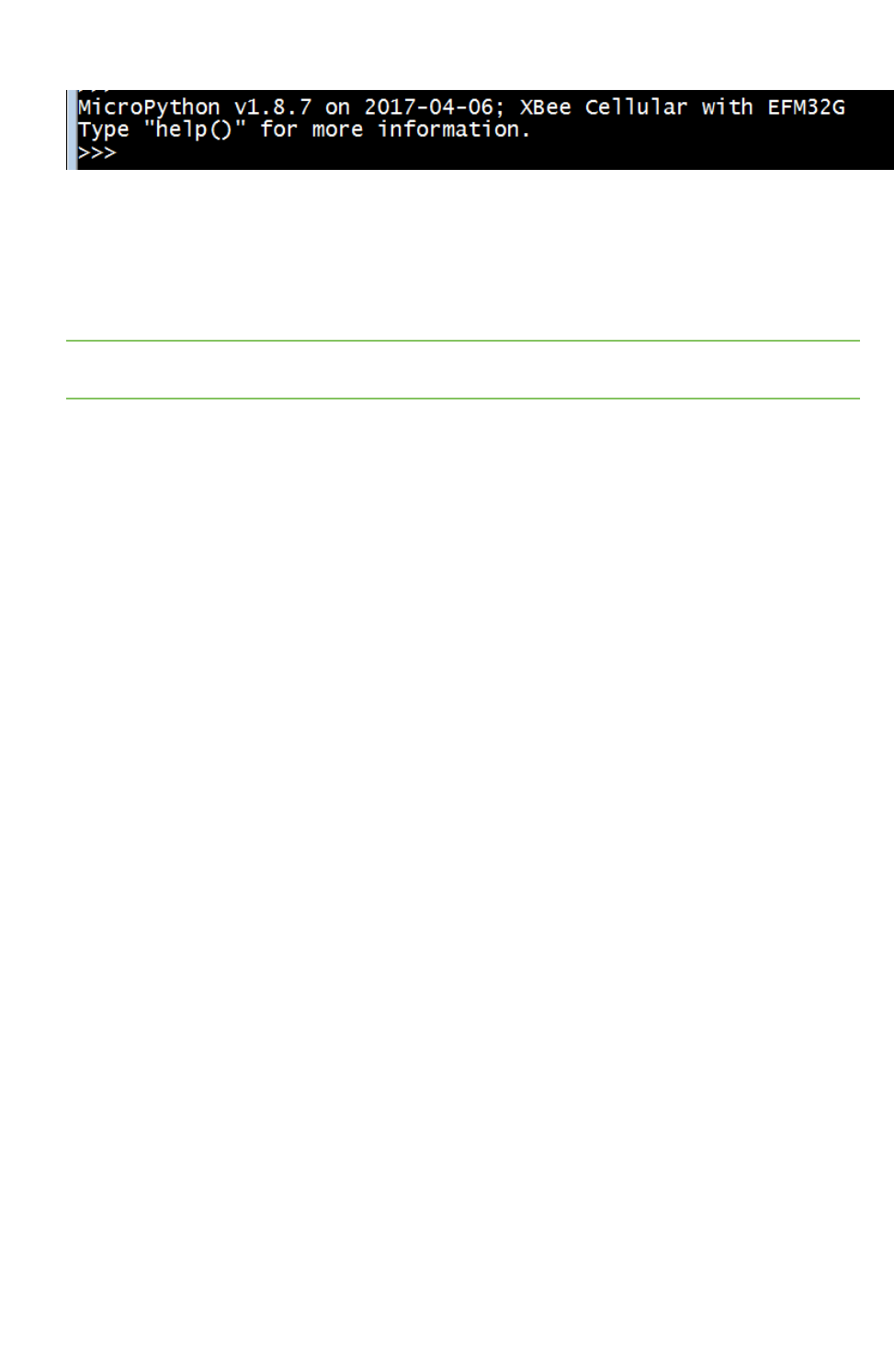
Get started with MicroPython Use picocom in Linux
Digi XBee3 Cellular LTE Cat 1 Smart Modem User Guide 57
Now you can type MicroPython commands at the >>> prompt.
Use picocom in Linux
With the XBee Smart Modem in MicroPython mode (AP =4), you can access the MicroPython prompt
using a terminal.
Note The user must have read and write permission for the serial port the XBee Smart Modem is
connected to in order to communicate with the device.
1. Open a terminal in Linux and type picocom -b 115200 /dev/ttyUSB0. This assumes you have
no other USB-to-serial devices attached to the system.
2. Press Ctrl+Bto get the MicroPython version banner and prompt. You can also press Enter to
bring up the prompt.
If you do have other USB-to-serial devices attached:
1. Before attaching the XBee Smart Modem, check the directory /dev/ for any devices named
ttyUSBx, where xis a number. An easy way to list these is to type: ls /dev/ttyUSB*. This
produces a list of any device with a name that starts with ttyUSB.
2. Take note of the devices present with that name, and then connect the XBee Smart Modem.
3. Check the directory again and you should see one additional device, which is the XBee Smart
Modem.
4. In this case, replace /dev/ttyUSB0 at the top with /dev/ttyUSB<number>, where <number>
is the new number that appeared.
5. It should connect and show Terminal ready.
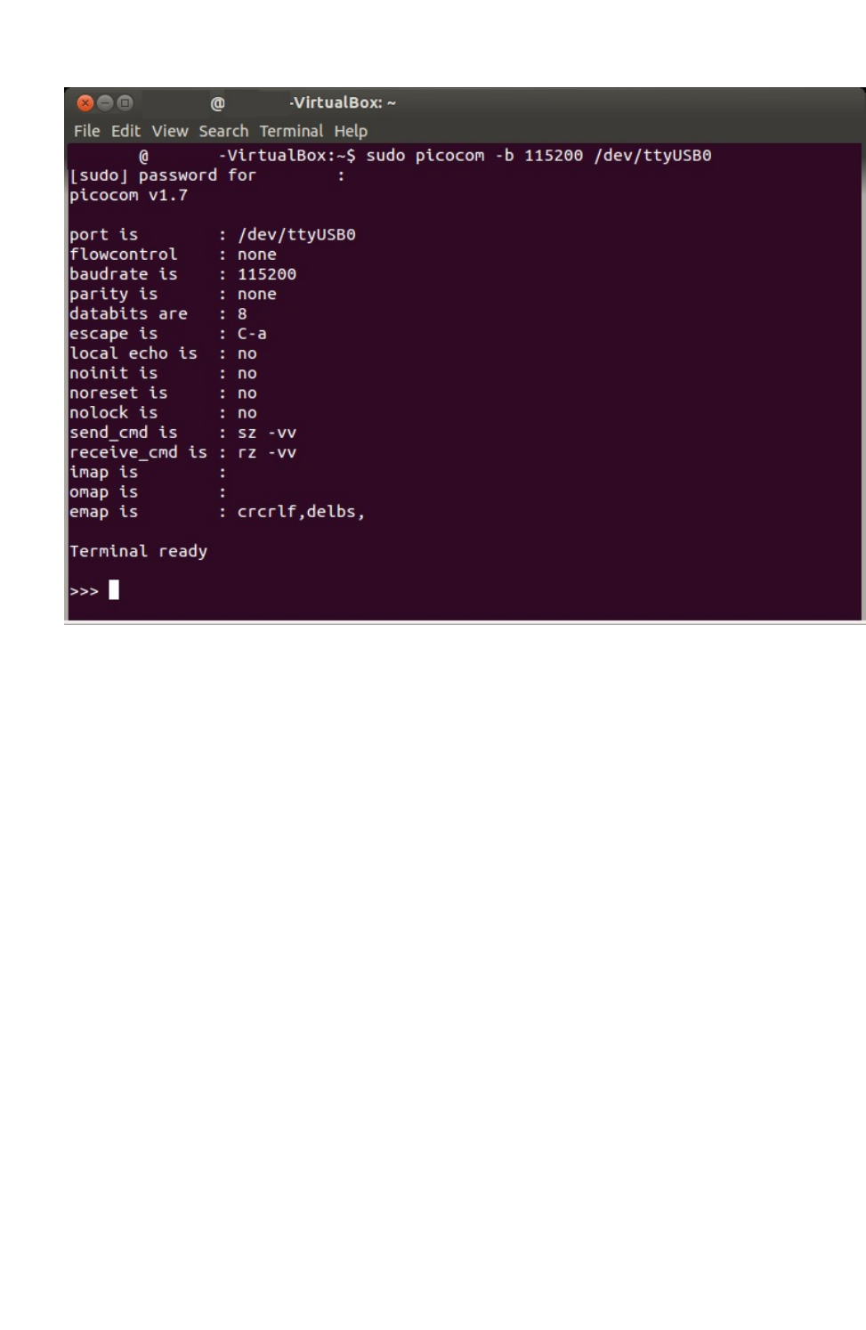
Get started with MicroPython Use picocom in Linux
Digi XBee3 Cellular LTE Cat 1 Smart Modem User Guide 58
Now you can type MicroPython commands at the >>> prompt.


Technical specifications Interface and hardware specifications
Digi XBee3 Cellular LTE Cat 1 Smart Modem User Guide 60
Interface and hardware specifications
The following table provides the interface and hardware specifications for the device.
Specification Value
Dimensions 2.438 x 3.294 cm (0.960 x 1.297 in)
Weight 5 g (0.18 oz)
Operating temperature -40 to +80 °C
Antenna connector U.FL for primary and secondary antennas
Digital I/O 13 I/O lines
ADC 4 10-bit analog inputs
RF characteristics
The following table provides the RF characteristics for the device.
Specification Cellular value Bluetooth value
Modulation LTE/4G – QPSK, 16 QAM QPSK
Transmit power 23 dBm 9 dBm
Receive sensitivity -102 dBm -92 dBm
Over-the-air maximum data rate 10 Mb/s 2 Mb/s
Networking specifications
The following table provides the networking and carrier specifications for the device.
Specification Value
Addressing options TCP/IPand SMS
Carrier and technology AT&T LTE Cat 1
Supported bands 2, 4 and 12
Security SSL/TLS
Power requirements
The following table provides the power requirements for the device.
Specification Value
Supply voltage range 3.0 to 5.5 VDC
Extended voltage range 2.7 to 5.5 VDC

Technical specifications Power consumption
Digi XBee3 Cellular LTE Cat 1 Smart Modem User Guide 61
Power consumption
Specification State
Average
current Peak current
2.4 GHz TX Active transmit @ 3.3 V 70 mA
2.4 GHz RX Active receive @ 3.3 V 30 mA
Cellular Tx+RX current Active transmit, 23 dBm @ 3.3 V 860 mA 1020 mA, Bluetooth
disabled
1080 mA, Bluetooth
enabled
Cellular Tx+RX current Active transmit, 23 dBm @ 5.0 V 555 mA 630 mA, Bluetooth
disabled
680 mA, Bluetooth
enabled
Cellular TX Only
current
Activetransmit,23dBm@3.3V 680 mA N/A
Cellular Rx + ACK
current
Active receive @ 3.3 V 530 mA N/A
Cellular Rx + ACK
current
Active receive @ 5 V 360 mA N/A
Cellular RX Only
current
Active receive @ 3.3 V 300 mA N/A
Idle current Idle/connected, listening @ 3.3
V
110 mA N/A
Idle current Idle/connected, listening @ 5 V 75 mA N/A
Sleep current Notconnected,Deep
Sleep@3.3V
12 µA N/A
Electrical specifications
The following table provides the electrical specifications for the XBee Smart Modem.
Symbol Parameter Condition Min Typical Max Units
VCCMAX Maximum limits
of VCC line
0 5.5 V
VDD_IO Internal supply
voltage for I/O
While in deep sleep and
during initial power up
Min
(VCC-
0.3,3.3)
3.3 V
VDD_IO Internal supply
voltage for I/O
In normal running mode 3.3 V V

Technical specifications Regulatory approvals
Digi XBee3 Cellular LTE Cat 1 Smart Modem User Guide 62
Symbol Parameter Condition Min Typical Max Units
VI Voltage on 5 V
tolerant pins
XBee pin 6 0.3 Min
(5.25,VDD_
IO+2)1
V
Other input pins 0.3 VDD_IO +
0.3
V
VIL Input low voltage 0.3*VDD_IO V
VIH Input high
voltage
0.7*VDD_
IO
V
VOL Voltage output
low
Sinking 3 mA VDD_IO = 3.3 V 0.2*VDD_IO V
VOH Voltage output
high
Sourcing 3 mA VDD_IO = 3.3
V
0.8*VDD_
IO
V
I_IN Input leakage
current
High Z state I/O connected
to Ground or VDD_IO
0.1 100 nA
RPU Internal pull-up
resistor
Enabled 40 kΩ
RPD Internal pull-
down resistor
Enabled 40 kΩ
Regulatory approvals
The following table provides the regulatory and carrier approvals for the device.
Specification Value
Model XB3C1
United States FCC ID: MCQ-XB3C1
Contains FCC ID:RI7XE866A1NA
Innovation, Science and Economic Development Canada (ISED) IC: 1846A-XB3C1
Contains IC: 5131A-XE866A1NA
Europe (CE) N/A
RoHS Lead-free and RoHS compliant
Australia N/A
Verizon end-device certified No
AT&T end-device certified Yes
PTCRB end-device certified Yes
1Pin 6 is also 5 V tolerant even when the XBee Smart Modem is not powered. We recommend only driving this
pin with 3.3 V for compatibility with other XBee products. The VBUS line is not used to enable/disable USB on
this product.

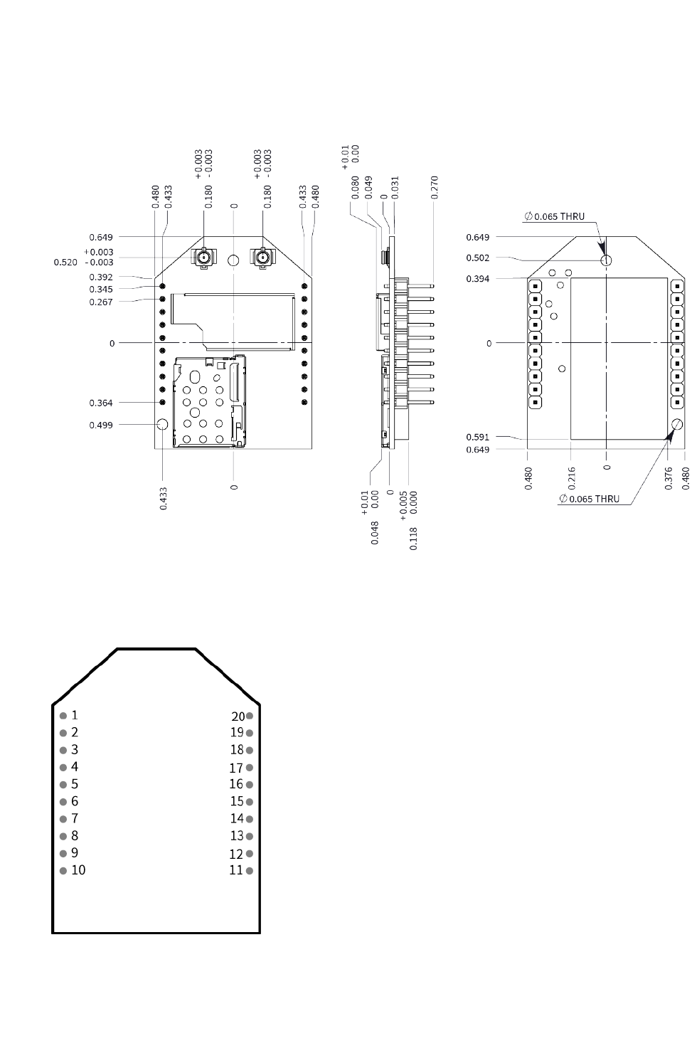
Hardware Mechanical drawings
Digi XBee3 Cellular LTE Cat 1 Smart Modem User Guide 64
Mechanical drawings
The following figures show the mechanical drawings for the XBee Smart Modem. All dimensions are in
inches.
Pin signals
The pin locations are:

Hardware Pin signals
Digi XBee3 Cellular LTE Cat 1 Smart Modem User Guide 65
The following table shows the pin assignments for the through-hole device. In the table, low-asserted
signals have a horizontal line above signal name.
Pin Name Direction Default Description
1VCC Power supply
2 DOUT Output Output UART Data Out
3DIN / CONFIG Input Input UART Data In
4 DIO12 / SPI_MISO Either Disabled Digital I/O 12 or SPI Slave Output line1
5 RESET Input
6 PWM0 / RSSI /
DIO10/USB_VBUS
Either Output PWM Output 0 / RX Signal Strength Indicator /
Digital I/O 10
7 DIO11/USB D+ Either Disabled Digital I/O 11 or USB Direct D+ line
8 USB D- USB Direct D- line
9DTR / SLEEP_RQ/
DIO8
Either Disabled Pin Sleep Control Line or Digital I/O 8
10 GND Ground
11 DIO4 / SPI_MOSI Either Disabled Digital I/O 4 or SPI Slave Input Line
12 CTS / DIO7 Either Output Output Clear-to-Send Flow Control or Digital I/O 7
13 ON /SLEEP/DIO9 Output Output Module Status Indicator or Digital I/O 9
14 VREF - Feature not supported on this device. Used on
other XBee devices for analog voltage reference.
15 Associate / DIO5 Either Output Associated Indicator, Digital I/O 5
16 RTS / DIO6 Either Disabled Input Request-to-Send Flow Control, Digital I/O 6
17 AD3/DIO3/SPI_
SS
Either Disabled Analog Input 3 or Digital I/O 3, SPI low enabled
select line
18 AD2 / DIO2 / SPI_
CLK
Either Disabled Analog Input 2 or Digital I/O 2, SPI Clock line
19 AD1/DIO1/ SPI_
ATTN
Either Disabled Analog Input 1 or Digital I/O 1, SPI Attention line
output
20 AD0/DIO0 Either Input Analog Input 0, Digital I/O 0
Pin connection recommendations
To ensure compatibility with future updates, make USB D+ and D- (pin 7 and pin 8) available in your
design.
1DIO12/SPI_MISO and DIO4/SPI_MOSI (pin 4 and pin 11) may optionally be configured as a secondary UART
serial port using MicroPython. See the Digi MicroPython Programming Guide for details.
Hardware RSSI PWM
Digi XBee3 Cellular LTE Cat 1 Smart Modem User Guide 66
The recommended minimum pin connections are VCC, GND, DIN, DOUT, RTS, DTR and RESET.
Firmware updates require access to these pins.
RSSI PWM
The XBee Smart Modem features an RSSI/PWM pin (pin 6) that, if enabled, adjusts the PWM output to
indicate the signal strength of the cellular connection. Use P0 (DIO10/PWM0 Configuration) to enable
the RSSI pulse width modulation (PWM) output on the pin. If P0 is set to 1, the RSSI/PWM pin outputs a
PWM signal where the frequency is adjusted based on the received signal strength of the cellular
connection.
The RSSI/PWM output is enabled continuously unlike other XBee products where the output is enabled
for a short period of time after each received transmission. If running on the XBIB development board,
DIO10 is connected to the RSSI LEDs, which may be interpreted as follows:
PWM duty cycle
Number of LEDs turned
on Received signal strength (dBm)
79.39% or more 3 -83 dBm or higher
62.42% to
79.39%
2 -93 to -83 dBm
45.45% to
62.42%
1 -103 to -93 dBm
Less than
45.45%
0Less than -103 dBm, or no cellular network
connection
SIM card
The XBee Smart Modem uses a 4FF (Nano) size SIM card.
CAUTION! Never insert or remove SIM card while the power is on!
The Associate LED
The following table describes the Associate LED functionality. For the location of the Associate LED on
the XBIB-U development board, see number 6 on the XBIB-U-DEV reference.
LED status
Blink
timing Meaning
On, solid Not joined to a mobile network.
Double blink ½second The last TCP/UDP/SMS attempt failed. If the LED has this pattern,
you may need to check DI (Remote Manager Indicator) or CI
(Protocol/Connection Indication) for the cause of the error.
Standardsingleblink 1second Normal operation.

Hardware The Associate LED
Digi XBee3 Cellular LTE Cat 1 Smart Modem User Guide 67
The normal association LED signal alternates evenly between high and low as shown below:
Where the low signal means LED off and the high signal means LED on.
When CI is not 0or 0xFF, the Associate LED has a different blink pattern that looks like this:

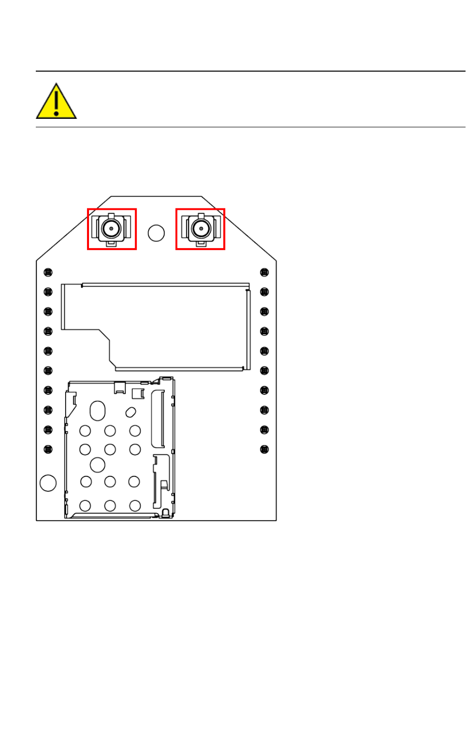
Antenna recommendations Antenna connections
Digi XBee3 Cellular LTE Cat 1 Smart Modem User Guide 69
Antenna connections
CAUTION! The XBee Smart Modem will not function properly with only the secondary
antenna port connected!
The XBee Smart Modem has two U.FL antenna ports; a primary on the upper left of the board and a
secondary port on the upper right, see the drawing below. You must connect the primary port and the
secondary port is optional. The secondary antenna improves receive performance in certain
situations, so we recommend it for best results.
See FCC-approved antennas for a list of approved antennas.
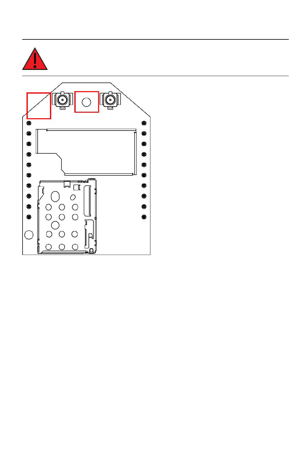
Antenna recommendations Keepout area
Digi XBee3 Cellular LTE Cat 1 Smart Modem User Guide 70
Connect the antenna cables as shown below.
WARNING! If you must run cables through the keepout area, keep them out of the left
area, and do not cover the embedded antennas.
Keepout area
The following drawing shows important recommendations for designing with the PCB antenna
module using an embedded antenna for Bluetooth. Do not mount the surface-mount PCB antenna
module on the RF Pad footprint because that footprint requires a ground plane within the keepout
area.
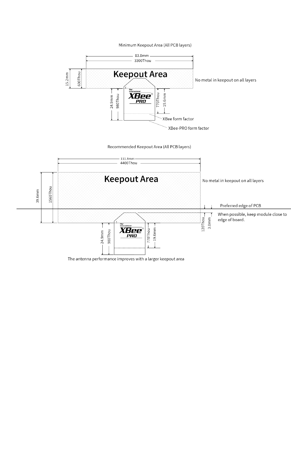
Antenna recommendations Antenna placement
Digi XBee3 Cellular LTE Cat 1 Smart Modem User Guide 71
Through-hole keepout
Notes
1. We recommend non-metal enclosures. For metal enclosures, use an external antenna.
2. Keep metal chassis or mounting structures in the keepout area at least 2.54 cm (1 in) from the
antenna.
3. Maximize the distance between the antenna and metal objects that might be mounted in the
keepout area.
4. These keepout area guidelines do not apply for wire whip antennas or external RFconnectors.
Wire whip antennas radiate best over the center of a ground plane.
Antenna placement
For optimal cellular reception, keep the antenna as far away from metal objects and other electronics
(including the XBee Smart Modem) as possible. Often, small antennas are desirable, but come at the
cost of reduced range and efficiency.

Design recommendations Cellular component firmware updates
Digi XBee3 Cellular LTE Cat 1 Smart Modem User Guide 73
Cellular component firmware updates
Even if you do not plan to use the USB interface (Pin 7 and 8), we strongly recommend you provide a
way to access the USB pins (Pin 7 and 8) to support direct firmware updates of the Cellular modem.
You should keep Pins 7 and 8 routing as a 90 ohm diff pair for USB communications.
CAUTION! If you do not provide access to these USB pins, you may be unable to perform
cellular component firmware updates.
One way to provide access to the USB interface is to connect the USB pins to a header or USB
connector on the host design; see USB Direct design for more information. At a minimum you should
connect pins 7 and 8 to test points so they are easy to wire to a connector if necessary.
If you are using the USB pins for other purposes you must provide a way to disconnect those
interfaces during USB operation, such as using zero ohm resistors.
USB Direct design
Connect USB data pins 7 and 8 (USB_D+ and USB_D- respectively) on the XBee Smart Modem to the
appropriate pins on the host processor or connector. You may optionally connect pin 6 to VBUS for
future compatibility, but the VBUS feature is not supported on this product. See USB direct mode for
more information on how USB is enabled and disabled.
The USB interface follows the USB 2.0 high speed specification and data lines must be designed as a
90 Ωdifferential pair. Both traces should be the same length and the overall trace length should be
kept as short as possible. If you are connecting to a USB connector then we recommend that you
employ an ESD suppressor appropriate for USB 2.0 HS (for example the Littelfuse PESD0402-140).
Other than the ESD suppressor, do not place additional components in the signal paths. The
suppressor is not needed if you are connecting to an on-board host processor.
CAUTION! If you use pins 7 and 8 for USB you must dedicate the pins to that interface.
Adding any traces to the main USB trace and/or connecting those traces to other
components will introduce signal integrity issues, which may result in unreliable USB
operation.
Power supply considerations
When considering a power supply, use the following design practices.
1. Power supply ripple should be less than 75 mV peak to peak.
2. The power supply should be capable of providing a minimum of 1.5 A at 3.3 V (5 W). Keep in
mind that operating at a lower voltage requires higher current capability from the power
supply to achieve the 5 W requirement.
3. Place sufficient bulk capacitance on the XBee VCC pin to maintain voltage above the minimum
specification during inrush current. Inrush current is about 2 A during initial power up of cellular
communications and wakeup from sleep mode.
4. Place smaller high frequency ceramic capacitors very close to the XBee Smart Modem VCC pin
to decrease high frequency noise.
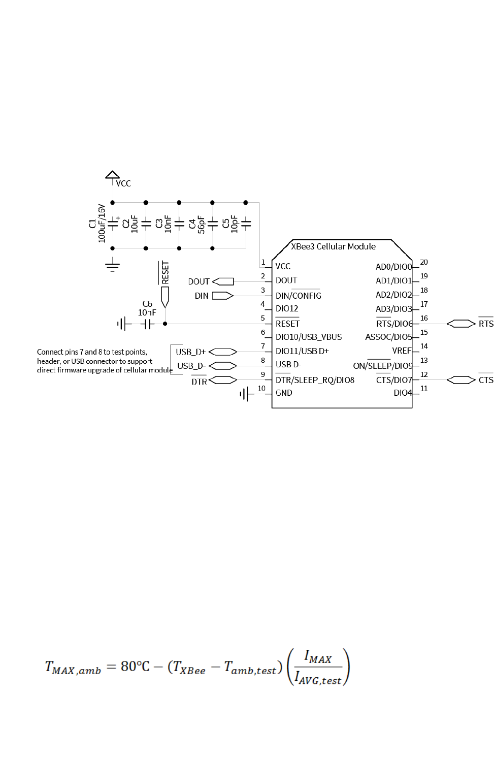
Design recommendations Recommended application circuit
Digi XBee3 Cellular LTE Cat 1 Smart Modem User Guide 74
5. Use a wide power supply trace or power plane to ensure it can handle the peak current
requirements with minimal voltage drop. We recommend that the power supply and trace be
designed such that the voltage at the XBee VCC pin does not vary by more than 0.1 V between
light load (~0.5 W) and heavy load (~3 W).
Recommended application circuit
In high EMI noise environments, we recommend adding a 10 nF ceramic capacitor very close to pin 5.
Heat considerations and testing
The XBee Smart Modem may generate significant heat during sustained operation. In addition to
heavy data transfer, other factors that can contribute to heating include ambient temperature, air
flow around the device, and proximity to the nearest cellular tower (the XBee Smart Modem must
transmit at a higher power level when communicating over long distances). Overheating can cause
device malfunction and potential damage. In order to avoid this it is important to consider the
application the XBee Smart Modem is going into and mitigate heat issues if necessary. We recommend
that you perform thermal testing in your application to determine the resulting steady state
temperature of the XBee Smart Modem. Use TP (Temperature) to estimate the device temperature.
Convert the TP reading from hex format to decimal.
You also need to know the ambient temperature and the average current consumption during your
test. If you do not have a way to measure current consumption you can estimate it from the table in
the next section.
Use those results to approximate the maximum safe ambient temperature for the XBee Smart
Modem, TMAX,amb, with the following equation:
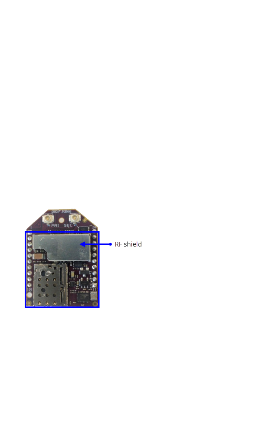
Design recommendations Heat sink guidelines
Digi XBee3 Cellular LTE Cat 1 Smart Modem User Guide 75
Where:
TXBee is the steady state temperature of the XBee Smart Modem that you measured during your test
(if using the TP command, be sure to convert from hex format to decimal).
Tamb,test is the ambient air temperature during your test.
IAVG,test is the average current measured during your test.
IMAX is the average current draw expected for your application when transmitting at maximum RF
power; see Power consumption.
Heat sink guidelines
Based on the results of your thermal testing you may find it is advisable or required to implement a
method of dissipating excess heat. This section explains how to employ a heat sink on top of the XBee
Smart Modem.
A bolt-down style heat sink on top of the XBee Smart Modem provides the best performance. An
example part number is Advanced Thermal Solutions ATS-PCBT1084/ATS-PCB1084. You must use an
electrically non-conductive thermal gasket on top of the XBee device under the area that will be
covered by the heat sink. A thermal gasket such as Gap Pad® 2500S20 is suitable for this purpose. We
recommend using a gasket with thickness of at least 0.080 in to ensure that components on top of
the XBee device do not tear through the material when pressure is applied to the heat sink.
Install the SIM card prior to placement of the heat sink. Position the thermal gasket and heat sink
assembly on the top of the device so that it covers the entire section shown inside the blue box below
(covering the RF shield with thermal gasket is optional because the RF shield is allowed to directly
contact the heat sink). Do not cover the U.FL connectors.
When attaching to the host PCB, tighten the mounting hardware until the gasket is compressed at
least 25% and the heat sink is snug against the RF shield. Avoid overtightening. To prevent shorting,
check that the surface of the heat sink does not directly contact any of the XBee device components.
You may also use an adhesive style heat sink with the XBee Smart Modem, such as Wakefield-Vette
658-45ABT3. Follow the instructions above, except do not cover the area under the RF shield with
thermal gasket; connect this surface directly to the heat sink for mechanical strength. The thermal
gasket must be used on top of all other components under the heat sink to prevent shorting and
provide effective thermal transfer to the heat sink.
The following table provides a list of typical scenarios and the maximum ambient temperature at
which the XBee Smart Modem can be safely operated under that condition. These are provided only as
guidelines as your results will vary based on application. We recommend that you perform sufficient

Design recommendations Add a fan to provide active cooling
Digi XBee3 Cellular LTE Cat 1 Smart Modem User Guide 76
testing, as explained in Heat considerations and testing, to ensure that the XBee Smart Modem does
not exceed temperature specifications.
Scenario
Average current
consumption
(VCC = 3.3V) Example application
Peak data
consumed
(MB/hr)
Maximum safe
ambient
temperature
No
heat
sink
Heat
sink
Heat
sink
and
fan
Maximum
transmission duty
cycle
950 mA Running video camera 500 to
2000
N/A 40 C 60 C
50% duty cycle 475 mA Running low resolution
video camera
200 to 400 42 C 65 C 75 C
20% duty cycle 200 mA Sending high resolution
photo less than once per
minute
50 to 150 64 C 74 C 78 C
Device awake,
limited
transmissions
170 mA Updating traffic sign 1 to 10 66 C 75 C 80 C
Device primarily
asleep, very
limited
transmissions
20 mA Small data
transmission/receptions
which occur once per
hour
Less than
0.1
80 C 80 C 80 C
Add a fan to provide active cooling
Another option for heat mitigation is to add a fan to your system to provide active cooling. You can use
a fan instead of or in addition to a heat sink. The XBee Smart Modem offers a fan control feature on
I/O pin DIO11 (pin 7). When the functionality is enabled, that line is pulled high to indicate when the fan
should be turned on. The line is pulled high when the device gets above 70 °C and the cellular
component is running, and turns off when the device drops below 65 °C.
To enable the functionality set P1 (DIO11/PWM1 Configuration) to 1. Note that the I/O pin is not
capable of driving a fan directly; you must implement a circuit to power the fan from a suitable power
source.


Cellular connection process Connecting
Digi XBee3 Cellular LTE Cat 1 Smart Modem User Guide 78
Connecting
In normal operations, the XBee Smart Modem automatically attempts both a cellular network
connection and a data network connection on power-up. The sequence of these connections is as
follows:
Cellular network
1. The device powers on.
2. It looks for cellular towers.
3. It chooses a candidate tower with the strongest signal.
4. It negotiates a connection.
5. It completes cellular registration; the phone number and SMS are available.
Data network connection
1. The network enables the evolved packet system (EPS) bearer with an access point name
(APN). See AN (Access Point Name) if you have APNissues. You can use OA (Operating APN) to
query the APN value currently configured in the cellular component.
2. The device negotiates a data connection with the access point.
3. The device receives its IP configuration and address.
4. The AI (Association Indication) command now returns a 0and the sockets become available.
Data communication with remote servers (TCP/UDP)
Once the data network connection is established, communication with remote servers can be
initiated in several ways:
nTransparent mode data sent to the serial port (see TD (Text Delimiter) and RO (Packetization
Timeout) for timing).
nAPI mode: Transmit (TX) Request: IPv4 - 0x20 received over the serial connection.
nDigi Remote Manager connectivity begins.
Data communication begins when:
1. A socket opens to the remote server.
2. Data is sent.
Data connectivity ends when:
1. The server closes the connection.
2. The TM timeout expires (see TM (IP Client Connection Timeout)).
3. The cellular network may also close the connection after a timeout set by the network
operator.
Disconnecting
When the XBee Smart Modem is put into Airplane mode or deep sleep is requested:

Cellular connection process SMS encoding
Digi XBee3 Cellular LTE Cat 1 Smart Modem User Guide 79
1. Sockets are closed, cleanly if possible.
2. The cellular connection is shut down.
3. The cellular component is powered off.
Note We recommend entering Airplane mode before resetting or rebooting the device to allow the
cellular module to detach from the network.
SMS encoding
The XBee Smart Modem transmits SMS messages using the standard GSM 03.38 character set.1
Because this character set only provides 7 bits of space per character, the XBee Smart Modem
ignores the most significant bit of each octet in an SMS transmission payload.
The device converts incoming SMS messages to ASCII. Characters that cannot be represented in
ASCIIare replaced with a space (' ', or 0x20 in hex). This includes emoji and other special characters.
1Also referred to as the GSM 7-bit alphabet.

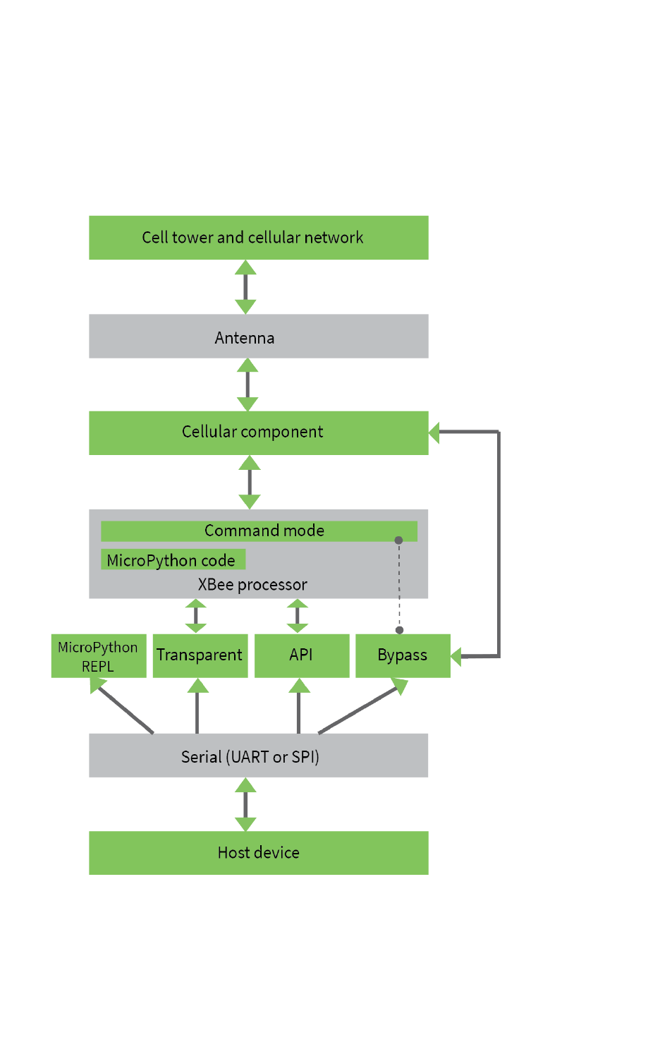
Modes Select an operating mode
Digi XBee3 Cellular LTE Cat 1 Smart Modem User Guide 81
Select an operating mode
The XBee Smart Modem interfaces to a host device such as a microcontroller or computer through a
logic-level asynchronous serial port. It uses a UART for serial communication with those devices.
The XBee Smart Modem supports three operating modes: Transparent operating mode, APIoperating
mode, and Bypass operating mode. The default mode is Transparent operating mode. Use the AP (API
Enable) command to select a different operating mode.
The following flowchart illustrates how the modes relate to each other.
Modes Transparent operating mode
Digi XBee3 Cellular LTE Cat 1 Smart Modem User Guide 82
Transparent operating mode
Devices operate in this mode by default. The device acts as a serial line replacement when it is in
Transparent operating mode. The device queues all serial data it receives through the DIN pin for RF
transmission. When a device receives RF data, it sends the data out through the DOUT pin. You can set
the configuration parameters using Command mode.
The IP (IP Protocol) command setting controls how Transparent operating mode works for the XBee
Smart Modem.
Note Transparent operation is not available when using SPI.
API operating mode
API operating mode is an alternative to Transparent operating mode. API mode is a frame-based
protocol that allows you to direct data on a packet basis. The device communicates UART or SPI data
in packets, also known as API frames. This mode allows for structured communications with
computers and microcontrollers.
The advantages of APIoperating mode include:
nIt is easier to send information to multiple destinations
nThe host receives the source address for each received data frame
nYou can change parameters without entering Command mode
Bypass operating mode
CAUTION! Bypass operating mode is an alternative to Transparent and API modes for
advanced users with special configuration needs. Changes made in this mode might
change or disable the device and we do not recommended it for most users.
In Bypass mode, the device acts as a serial line replacement to the cellular component. In this mode,
the XBee Smart Modem exposes all control of the cellular component's AT port through the UART. If
you use this mode, you must setup the cellular modem directly to establish connectivity. The modem
does not automatically connect to the network.
Note The cellular component can become unresponsive in Bypass mode. See Unresponsive cellular
component in Bypass mode for help in this situation.
When Bypass mode is active, most of the XBee Smart Modem's AT commands do not work. For
example, IM (IMEI)may never return a value, and DB does not update. In this configuration, the
firmware does not test communication with the cellular component (which it does by sending AT
commands). This is useful in case you have reconfigured the cellular component in a way that makes it
incompatible with the firmware. Bypass operating mode exists for users who wish to communicate
directly with the cellular component settings and do not intend to use XBee Smart Modem software
features such as API mode.
Command mode is available while in Bypass mode; see Enter Command mode for instructions.
Enter Bypass operating mode
To configure a device for Bypass operating mode:

Modes USB direct mode
Digi XBee3 Cellular LTE Cat 1 Smart Modem User Guide 83
1. Set the AP (API Enable) parameter value to 5.
2. Send WR (Write) to write the changes.
3. Send FR (Force Reset) to reboot the device.
4. After rebooting, enter Command mode and verify that Bypass operating mode is active by
querying AI (Association Indication) and confirming that it returns a value of 0x2F.
It may take a moment for Bypass operating mode to become active.
Leave Bypass operating mode
To configure a device to leave Bypass operating mode:
1. Set AP (API Enable) to something other than 5.
2. Send WR (Write) to write the changes.
3. Send FR (Force Reset) to reboot the device.
4. After rebooting, enter Command mode and verify that Bypass operating mode is not active by
querying AI (Association Indication) and confirming that it returns a value other than 0x2F.
Restore cellular settings to default in Bypass operating mode
Send AT&F1 to reset the cellular component to its factory profile.
USB direct mode
This mode allows you to replace the cellular component with the XBee Smart Modem such that the
USB lines are the same through a configuration option.
Enable USB direct mode
Set P1 (DIO11/PWM1 Configuration) to 7to enable USB direct mode. When set to 7DIO11/PWM1 (pin
7) brings out the USB D+ signal of the cellular component. The USB D- signal is available on pin 8. With
these pins connected to a USB host a direct connection is made to the cellular component which is not
mediated by the XBee processor.
When in USB direct mode AI (Association Indication) returns 0x2B.
Command mode
Command mode is a state in which the firmware interprets incoming characters as commands. It
allows you to modify the device’s configuration using parameters you can set using AT
commands.When you want to read or set any parameter of the XBee Smart Modem using this mode,
you have to send an AT command.Every AT command starts with the lettersATfollowed by the two
characters that identify the command and then by some optional configuration values.
The operating modes of the XBee Smart Modem are controlled by the AP (API Enable) setting,
butCommand mode is always available as a mode thedevice can enter while configured for any of the
operating modes.
Command mode is available on the UART interface for all operating modes. You cannot use the SPI
interface to enter Command mode.
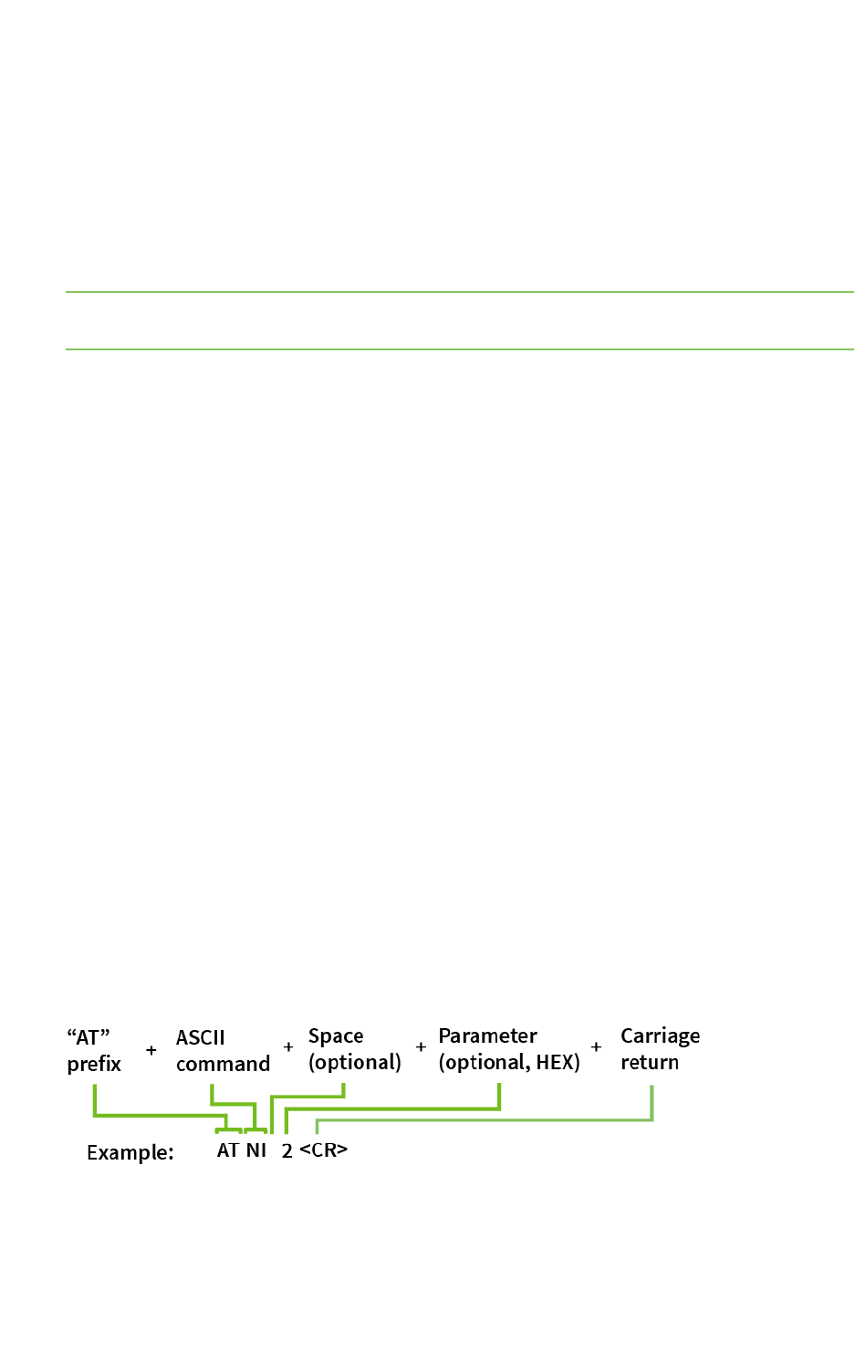
Modes Command mode
Digi XBee3 Cellular LTE Cat 1 Smart Modem User Guide 84
Enter Command mode
To get a device to switch into Command mode, you must issue the following sequence:+++within one
second. There must be at least one second preceding and following the+++sequence. Both the
command character (CC) and the silence before and after the sequence (GT) are configurable. When
the entrance criteria are met the device responds with OK\r on UART signifying that it has entered
Command mode successfully and is ready to start processing AT commands.
If configured to operate in Transparent operating mode, when entering Command mode the XBee
Smart Modem knows to stop sending data and start accepting commands locally.
Note Do not press Return or Enter after typing+++because it interrupts the guard time silence and
prevents you from entering Command mode.
When the device is in Command mode, it listens for user input and is able to receive AT commands on
the UART. IfCTtime (default is 10 seconds) passes without any user input, the device drops out of
Command mode and returns to the previous operating mode. You can force the device to leave
Command mode by sending CN (Exit Command mode).
You can customize the command character, the guard times and the timeout in the device’s
configuration settings. For more information, seeCC (Command Sequence Character),CT (Command
Mode Timeout)andGT (Guard Times).
Troubleshooting
Failure to enter Command mode is often due to baud rate mismatch. Ensure that the baud rate of the
connection matches the baud rate of the device. By default, BD (Baud Rate) =3(9600 b/s).
There are two alternative ways to enter Command mode:
nA serial break for six seconds enters Command mode. You can issue the "break" command
from a serial console, it is often a button or menu item.
nAsserting DIN (serial break) upon power up or reset enters Command mode. XCTU guides you
through a reset and automatically issues the break when needed.
Both of these methods temporarily set the device's baud rate to 9600 and return anOKon the UART
to indicate that Command mode is active. When Command mode exits, the device returns to normal
operation at the baud rate that BDis set to.
Send AT commands
Once the device enters Command mode, use the syntax in the following figure to send AT commands.
Every AT command starts with the lettersAT, which stands for "attention." TheATis followed by two
characters that indicate which command is being issued, then by some optional configuration values.
To read a parameter value stored in the device’s register, omit the parameter field.

Modes Command mode
Digi XBee3 Cellular LTE Cat 1 Smart Modem User Guide 85
Multiple AT commands
You can send multiple AT commands at a time when they are separated by a comma in Command
mode; for example,ATNIMy XBee,AC<cr>.
The preceding example changes theNI (Node Identifier) to My XBeeand makes the setting active
through AC (Apply Changes).
Parameter format
Refer to the list of AT commands for the format of individual AT command parameters. Valid formats
for hexidecimal values include with or without a leading0xfor exampleFFFFor0xFFFF.
Response to AT commands
When using AT commands to set parameters the XBee Smart Modem responds with OK<cr> if
successful and ERROR<cr> if not.
For devices with a file system:
ATAP1<cr>
OK<cr>
When reading parameters, the device returns the current parameter value instead of anOKmessage.
ATAP<cr>
1<cr>
Apply command changes
Any changes you make to the configuration command registers using AT commands do not take effect
until you apply the changes. For example, if you send theBDcommand to change the baud rate, the
actual baud rate does not change until you apply the changes. To apply changes:
1. Send AC (Apply Changes).
2. Send WR (Write).
or:
3. Exit Command mode.
Make command changes permanent
Send a WR (Write) command to save the changes. WR writes parameter values to non-volatile memory
so that parameter modifications persist through subsequent resets.
Send as RE command to wipe settings saved using WR back to their factory defaults.
Note You still have to use WR to save the changes enacted with RE.
Exit Command mode
1. Send CN (Exit Command mode) followed by a carriage return.
or:
2. If the device does not receive any valid AT commands within the time specified byCT
(Command Mode Timeout), it returns to Transparent or API mode. The default Command mode
timeout is10seconds.

Modes MicroPython mode
Digi XBee3 Cellular LTE Cat 1 Smart Modem User Guide 86
For an example of programming the device using AT Commands and descriptions of each configurable
parameter, see AT commands.
MicroPython mode
MicroPython mode (AP =4) allows you to communicate with the XBee Smart Modem using the
MicroPython programming language. You can use the MicroPython Terminal tool in XCTU to
communicate with the MicroPython stack of the XBee Smart Modem through the serial interface.
MicroPython mode connects the primary serial port to the stdin/stdout interface on MicroPython,
which is either the REPL or code launched at startup.
When code runs in MicroPython with AP set to a value other than 4, stdout goes to the bit bucket and
there is no input to read on stdin.


Sleep modes About sleep modes
Digi XBee3 Cellular LTE Cat 1 Smart Modem User Guide 88
About sleep modes
A number of low-power modes exist to enable devices to operate for extended periods of time on
battery power. Use SM (Sleep Mode) to enable these sleep modes.
Normal mode
Set SM to 0 to enter Normal mode.
Normal mode is the default sleep mode. If a device is in this mode, it does not sleep and is always
awake.
Devices in Normal mode are typically mains powered.
Pin sleep mode
Set SM to 1 to enter pin sleep mode.
Pin sleep allows the device to sleep and wake according to the state of the SLEEP_RQ pin (SLEEP_RQ).
When you assert SLEEP_RQ (high), the device finishes any transmit or receive operations, closes any
active connection, and enters a low-power state.
When you de-assert SLEEP_RQ (low), the device wakes from pin sleep.
Cyclic sleep mode
Set SM to 4 to enter Cyclic sleep mode.
Cyclic sleep allows the device to sleep for a specific time and wake for a short time to poll.
If you use the D7 command to enable hardware flow control, the CTS pin asserts (low) when the
device wakes and can receive serial data, and de-asserts (high) when the device sleeps.
Cyclic sleep with pin wake up mode
Set SM to 5 to enter Cyclic sleep with pin wake up mode.
This mode is a slight variation on Cyclic sleep mode (SM = 4) that allows you to wake a device
prematurely by de-asserting the SLEEP_RQ pin (SLEEP_RQ).
In this mode, you can wake the device after the sleep period expires, or if a high-to-low transition
occurs on the SLEEP_RQ pin.
Connected sleep mode
XBee Smart Modem hardware part number XB3-C-A1-UT-xxx can enter Connected sleep mode.
Set bit 0 of SO (Sleep Options) for connected sleep. When bit 0 is set and the XBee Smart Modem goes
to sleep, instead of the cellular component shutting down, it enters a lower power consumption mode
that maintains registration with the cellular network. This allows significantly faster resumption of
communications when coming out of sleep at the cost of additional power used.
Connected sleep mode draws 9 mA during sleep and 11 mA average over time (including periodically
waking up to maintain connection).

Sleep modes The sleep timer
Digi XBee3 Cellular LTE Cat 1 Smart Modem User Guide 89
The sleep timer
The sleep timer starts when the device wakes and resets on re-configuration. When the sleep timer
expires the device returns to sleep.
MicroPython sleep behavior
When the XBee Smart Modem enters Deep Sleep mode, any MicroPython code currently executing is
suspended until the device comes out of sleep. When the XBee Smart Modem comes out of sleep
mode, MicroPython execution continues where it left off.
Upon entering deep sleep mode, the XBee Smart Modem closes any active UDP connections and turns
off the cellular component. As a result, any sockets that were opened in MicroPython prior to sleep
report as no longer being connected. This behavior appears the same as a typical socket
disconnection event will:
nsocket.send raises OSError: ENOTCONN
nsocket.sendto raises OSError: ENOTCONN
nsocket.recv returns the empty string, the traditional end-of-file return value
nsocket.recvfrom returns an empty message, for example:
(b'', (<address from connect()>, <port from connect()>) )
The underlying UDP socket resources have been released at this point.


Power saving features Airplane mode
Digi XBee3 Cellular LTE Cat 1 Smart Modem User Guide 91
Airplane mode
While not technically a sleep mode, Airplane mode is another way of saving power. When set, the
cellular component of the XBee Smart Modem is fully turned off and no access to the cellular network
is performed or possible. Use AM (Airplane Mode) to configure this mode.

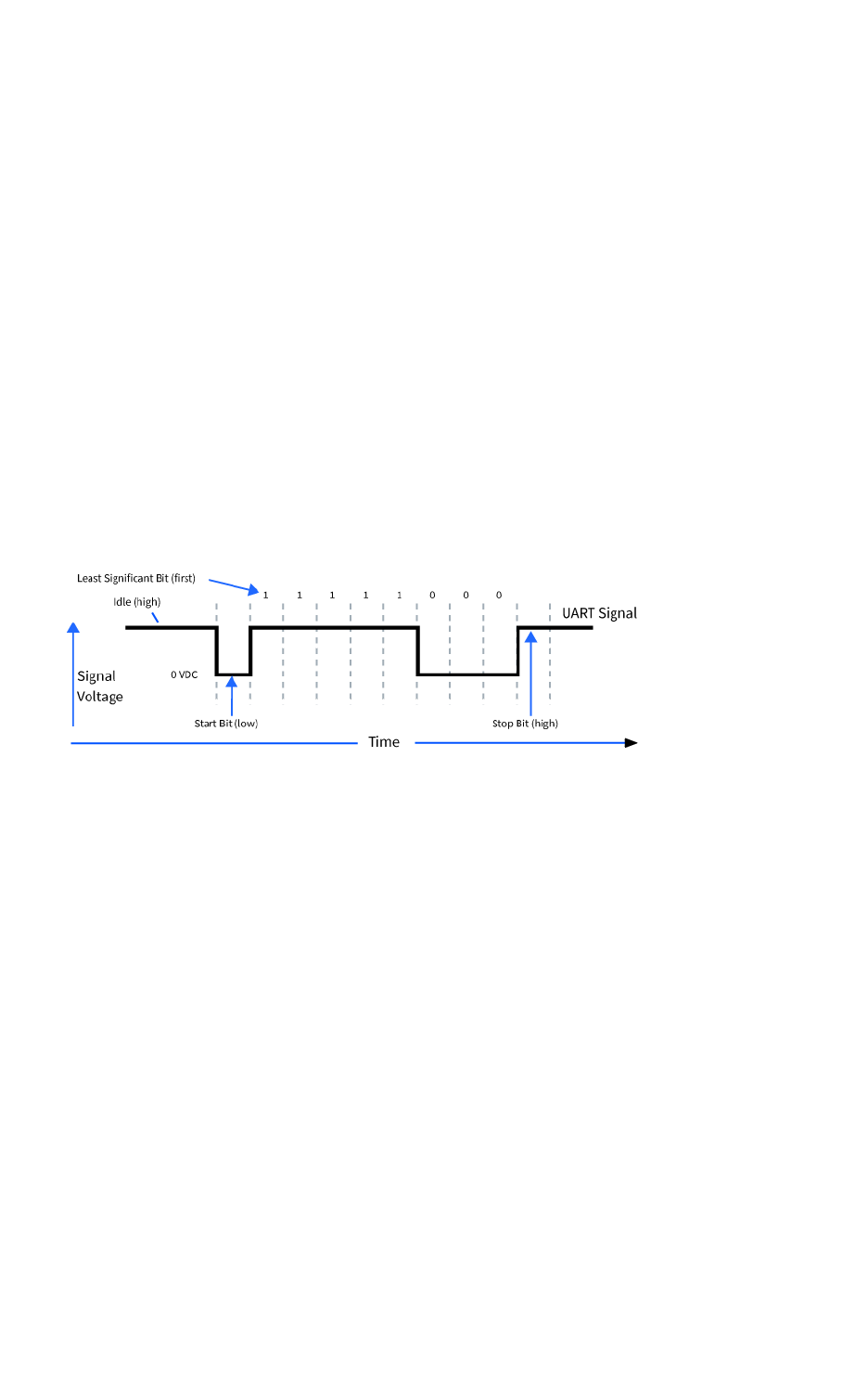
Serial communication Serial interface
Digi XBee3 Cellular LTE Cat 1 Smart Modem User Guide 93
Serial interface
The XBee Smart Modem interfaces to a host device through a serial port. The device's serial port can
communicate:
nThrough a logic and voltage compatible universal asynchronous receiver/transmitter (UART).
nThrough a level translator to any serial device, for example, through an RS-232 or USB
interface board.
nThrough a serial peripheral interface (SPI) port.
Serial data
A device sends data to the XBee Smart Modem's UART through pin 3 DIN as an asynchronous serial
signal. When the device is not transmitting data, the signals should idle high.
For serial communication to occur, you must configure the UART of both devices (the microcontroller
and the XBee Smart Modem) with compatible settings for the baud rate, parity, start bits, stop bits,
and data bits.
Each data byte consists of a start bit (low), 8 data bits (least significant bit first) and a stop bit (high).
The following diagram illustrates the serial bit pattern of data passing through the device. The
diagram shows UART data packet 0x1F (decimal number 31) as transmitted through the device.
You can configure the UART baud rate, parity, and stop bits settings on the device with the BD,NB,
and SB commands respectively. For more information, see Serial interfacing commands.
In the rare case that a device has been configured with the UART disabled, you can recover the device
to UART operation by holding DIN low at reset time. DIN forces a default configuration on the UART at
9600 baud and it brings the device up in Command mode on the UART port. You can then send the
appropriate commands to the device to configure it for UART operation. If those parameters are
written, the device comes up with the UART enabled on the next reset.
UART data flow
Devices that have a UART interface connect directly to the pins of the XBee Smart Modem as shown in
the following figure. The figure shows system data flow in a UART-interfaced environment. Low-
asserted signals have a horizontal line over the signal name.
Serial buffers
The XBee Smart Modem maintains internal buffers to collect serial and RF data that it receives. The
serial receive buffer collects incoming serial characters and holds them until the device can process
them. The serial transmit buffer collects the data it receives via the RF link until it transmits that data
out the serial or SPI port.

Serial communication CTS flow control
Digi XBee3 Cellular LTE Cat 1 Smart Modem User Guide 94
CTS flow control
We strongly encourage you to use flow control with the XBee Smart Modem to prevent buffer
overruns.
CTS flow control is enabled by default; you can disable it with D7 (DIO7/CTS). When the serial receive
buffer fills with the number of bytes specified by FT (Flow Control Threshold), the device de-asserts
CTS (sets it high) to signal the host device to stop sending serial data. The device re-asserts CTS when
less than FT-32 bytes are in the UART receive buffer.
Note Serial flow control is not possible when using the SPI port.
RTS flow control
If you set D6 (DIO6/RTS) to enable RTS flow control, the device does not send data in the serial
transmit buffer out the DOUT pin as long as RTS is de-asserted (set high). Do not de-assert RTS for
long periods of time or the serial transmit buffer will fill.
Enable UART or SPI ports
To enable the UART port, configure DIN and DOUT (P3 and P4 parameters) as peripherals. To enable
the SPI port, enable SPI_MISO, SPI_MOSI, SPI_SSEL , and SPI_CLK (P5 through P9) as peripherals. If
you enable both ports then output goes to the UART until the first input on SPI.
When both the UART and SPI ports are enabled on power-up, all serial data goes out the UART. As
soon as input occurs on either port, that port is selected as the active port and no input or output is
allowed on the other port until the next device reset.
If you change the configuration so that only one port is configured, then that port is the only one
enabled or used. If the parameters are written with only one port enabled, then the port that is not
enabled is not used even temporarily after the next reset.
If both ports are disabled on reset, the device uses the UART in spite of the wrong configuration so
that at least one serial port is operational.

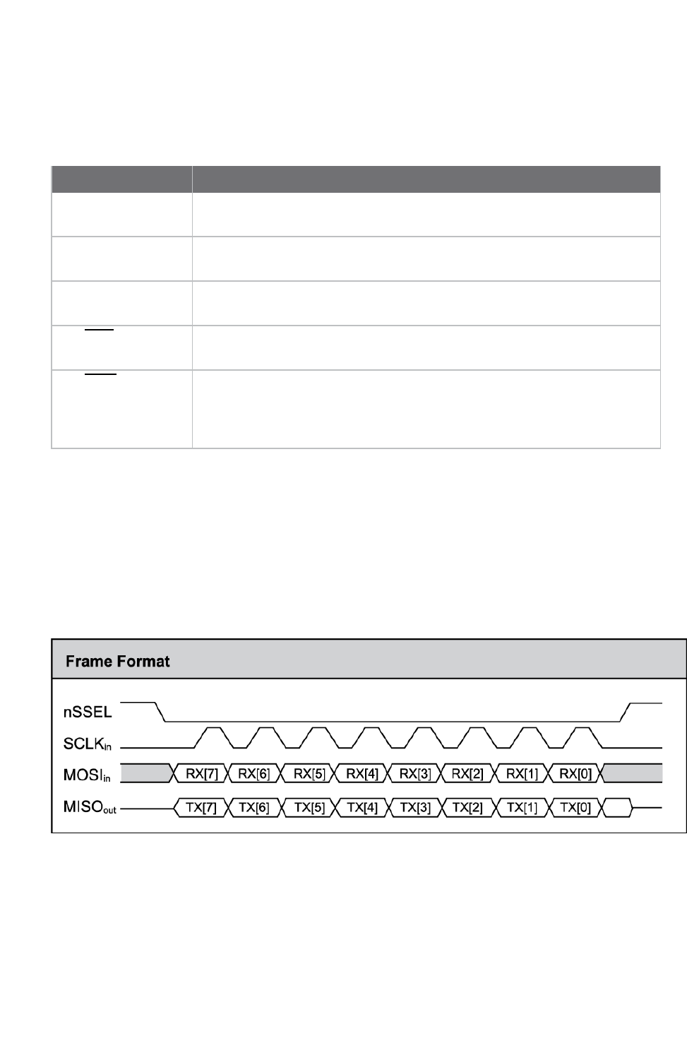
SPI operation SPI communications
Digi XBee3 Cellular LTE Cat 1 Smart Modem User Guide 96
SPI communications
The XBee Smart Modem supports SPI communications in slave mode. Slave mode receives the clock
signal and data from the master and returns data to the master. The following table shows the
signals that the SPI port uses on the device.
Signal Function
SPI_MOSI
(MasterOut,SlaveIn)
Inputs serial data from the master
SPI_MISO(Master
In,Slave Out)
Outputs serial data to the master
SPI_SCLK
(SerialClock)
Clocks data transfers on MOSI and MISO
SPI_SSEL
(SlaveSelect)
Enables serial communication with the slave
SPI_ATTN (Attention) Alerts the master that slave has data queued to send. The XBee Smart
Modem asserts this pin as soon as data is available to send to the SPI
master and it remains asserted until the SPI master has clocked out all
available data.
In this mode:
nSPI clock rates up to 4.8 MHz are possible.
nData is most significant bit (MSB) first; bit 7 is the first bit of a byte sent over the interface.
nFrame Format mode 0 is used. This means CPOL= 0 (idle clock is low) and CPHA = 0 (data is
sampled on the clock’s leading edge).
nThe SPI port only supports API Mode (AP =1).
The following diagram shows the frame format mode 0 for SPI communications.
SPI mode is chip to chip communication. We do not supply a SPI communication option on the device
development evaluation boards.
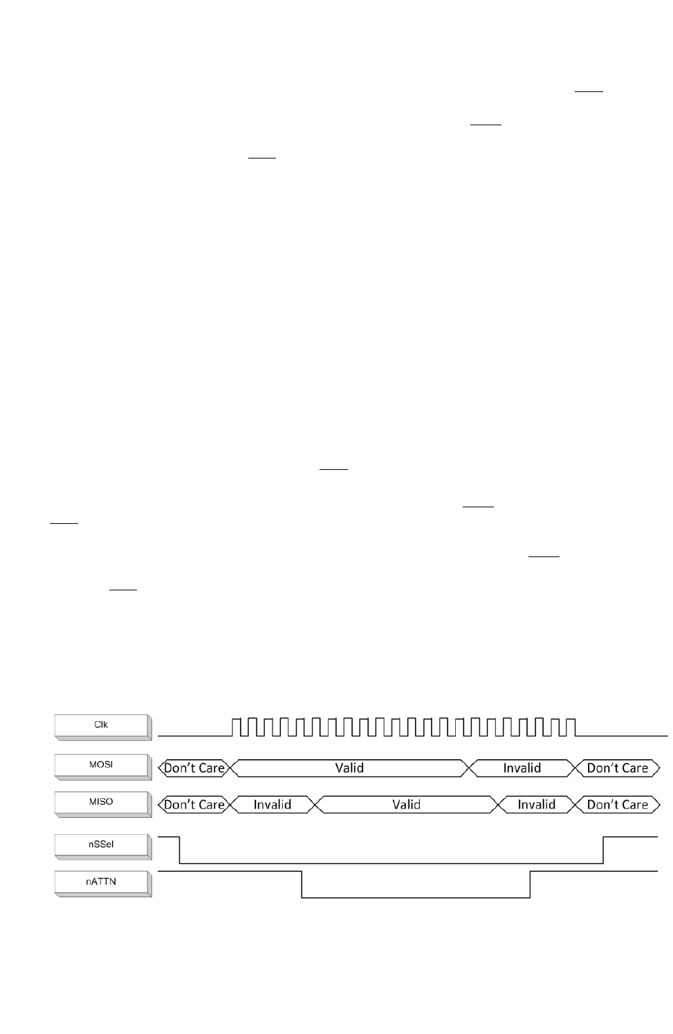
SPI operation Full duplex operation
Digi XBee3 Cellular LTE Cat 1 Smart Modem User Guide 97
Full duplex operation
The specification for SPI includes the four signals SPI_MISO, SPI_MOSI, SPI_CLK, and SPI_SSEL. Using
these four signals, the SPI master cannot know when the slave needs to send and the SPI slave
cannot transmit unless enabled by the master. For this reason, the SPI_ATTN signal is available in the
design. This allows the SPI slave to alert the SPI master that it has data to send. In turn, the SPI
master is expected to assert SPI_SSEL and start SPI_CLK, unless these signals are already asserted
and active respectively. This, in turn, allows the XBee Smart Modem SPI slave to send data to the
master.
SPI data is latched by the master and slave using the SPI_CLK signal. When data is being transferred
the MISO and MOSI signals change between each clock. If data is not available then these signals will
not change and will be either 0 or 1. This results in receiving either a repetitive 0 or 0xFF. The means
of determining whether or not received data is valid is by packetizing the data with API packets,
without escaping. Valid data to and from the XBee Smart Modem is delimited by 0x7E, a length, the
payload, and finally a checksum byte. Everything else in both directions should be ignored. The bytes
received between frames will be either 0xff or 0x00. This allows the SPI master to scan for a 0x7E
delimiter between frames.
SPI allows for valid data from the slave to begin before, at the same time, or after valid data begins
from the master. When the master is sending data to the slave and the slave has valid data to send in
the middle of receiving data from the master, it allows a true full duplex operation where data is valid
in both directions for a period of time. During this time, the master and slave must simultaneously
transmit valid data at the clock speed so that no invalid bytes appear within an API frame, causing the
whole frame to be discarded.
An example follows to more fully illustrate the SPI interface during the time valid data is being sent in
both directions. First, the master asserts SPI_SSEL and starts SPI_CLK to send a frame to the slave.
Initially, the slave does not have valid data to send the master. However, while it is still receiving data
from the master, it has its own data to send. Therefore, it asserts SPI_ATTN low. Seeing that SPI_
SSEL is already asserted and that SPI_CLK is active, it immediately begins sending valid data, even
while it is receiving valid data from the master. In this example, the master finishes its valid data
before the slave does. The master will have two indications of valid data: The SPI_ATTN line is
asserted and the API frame length is not yet expired. For both of these reasons, the master should
keep SPI_SSEL asserted and should keep SPI_CLK toggling in order to receive the end of the frame
from the slave, even though these signals were originally turned on by the master to send data.
During the time that the SPI master is sending invalid data to the SPI slave, it is important no 0x7E is
included in that invalid data because that would trigger the SPI slave to start receiving another valid
frame.
The following figure illustrates the SPI interface while valid data is being sent in both directions.

SPI operation Low power operation
Digi XBee3 Cellular LTE Cat 1 Smart Modem User Guide 98
Low power operation
Sleep modes generally work the same on SPI as they do on UART. However, due to the addition of SPI
mode, there is an option of another sleep pin, as described below.
By default, Digi configures DIO8 (SLEEP_REQUEST) as a peripheral and during pin sleep it wakes the
device and puts it to sleep. This applies to both the UART and SPI serial interfaces.
If SLEEP_REQUEST is not configured as a peripheral and SPI_SSEL is configured as a peripheral, then
pin sleep is controlled by SPI_SSEL rather than by SLEEP_REQUEST. Asserting SPI_SSEL (pin 17) by
driving it low either wakes the device or keeps it awake. Negating SPI_SSEL by driving it high puts the
device to sleep.
Using SPI_SSEL to control sleep and to indicate that the SPI master has selected a particular slave
device has the advantage of requiring one less physical pin connection to implement pin sleep on SPI.
It has the disadvantage of putting the device to sleep whenever the SPI master negates SPI_SSEL
(meaning time is lost waiting for the device to wake), even if that was not the intent.
If the user has full control of SPI_SSEL so that it can control pin sleep, whether or not data needs to be
transmitted, then sharing the pin may be a good option in order to make the SLEEP_REQUEST pin
available for another purpose.
If the device is one of multiple slaves on the SPI, then the device sleeps while the SPI master talks to
the other slave, but this is acceptable in most cases.
If you do not configure either pin as a peripheral, then the device stays awake, being unable to sleep in
SM1 mode.
Select the SPI port
nD1 (This parameter will only be changed if it is at a default of zero when the method is
invoked.)
nD2
nD3
nD4
nP2
As long as the host does not issue a WR command, these configuration values revert to previous
values after a power-on reset. If the host issues a WR command while in SPI mode, these same
parameters are written to flash. After a reset, parameters that were forced and then written to flash
become the mode of operation.
If the UART is disabled and the SPI is enabled in the written configuration, then the device comes up in
SPI mode without forcing it by holding DOUT low. If both the UART and the SPI are enabled at the time
of reset, then output goes to the UART until the host sends the first input. If that first input comes on
the SPI port, then all subsequent output goes to the SPI port and the UART is disabled. If the first
input comes on the UART, then all subsequent output goes to the UART and the SPI is disabled.
When the master asserts the slave select (SPI_SSEL) signal, SPI transmit data is driven to the output
pin SPI_MISO, and SPI data is received from the input pin SPI_MOSI. The SPI_SSEL pin has to be
asserted to enable the transmit serializer to drive data to the output signal SPI_MISO. A rising edge
on SPI_SSEL causes the SPI_MISO line to be tri-stated such that another slave device can drive it, if so
desired.

SPI operation Force UART operation
Digi XBee3 Cellular LTE Cat 1 Smart Modem User Guide 99
Force UART operation
If you configure a device with only the SPI enabled and no SPI master is available to access the SPI
slave port, you can recover the device to UART operation by holding DIN / CONFIG low at reset time.
DIN/CONFIG forces a default configuration on the UART at 9600 baud and brings up the device in
Command mode on the UART port. You can then send the appropriate commands to the device to
configure it for UART operation. If you write those parameters, the device comes up with the UART
enabled on the next reset.
Data format
SPI only operates in API mode 1. The XBee Smart Modem does not support Transparent mode or API
mode 2 (which escapes control characters). This means that the AP configuration only applies to the
UART, and the device ignores it while using SPI. The reason for this operation choice is that SPI is full
duplex. If data flows in one direction, it flows in the other. Since it is not always possible to have valid
data flowing in both directions at the same time, the receiver must have a way to parse out the valid
data and to ignore the invalid data.
The XBee Smart Modem sends 0XFF when there is no data to send to the host.


File system Overview of the file system
Digi XBee3 Cellular LTE Cat 1 Smart Modem User Guide 101
Overview of the file system
XBee Smart Modem firmware versions ending in 0B (for example, 1130B, 100B, 3100B) and later
include support for storing files on an internal 1 MB SPI flash.
CAUTION! You need to format the file system if upgrading a device that originally
shipped with older firmware. You can use XCTU, AT commands or MicroPython for that
initial format or to erase existing content at any time.
Note To use XCTU with file system, you need XCTU6.4.0 or newer.
See ATFSFORMAT confirm and ensure that the format is complete.
Directory structure
The SPI flash appears in the file system as /flash, the only entry at the root level of the file system. It
has a lib directory intended for MicroPython modules and a cert directory for files used for SSL/TLS
sockets.
Paths
The XBee Smart Modem stores all of its files in the top-level directory /flash. On startup, the ATFS
commands and MicroPython each use that as their current working directory. When specifying the
path to a file or directory, it is interpreted as follows:
nPaths starting with a forward slash are "absolute" and must start with /flash to be valid.
nAll other paths are relative to the current working directory.
nThe directory .. refers to the parent directory, so an operation on ../filename.txt that takes
place in the directory /flash/test accesses the file /flash/filename.txt.
nThe directory .refers to the current directory, so the command ATFS ls . lists files in the
current directory.
nNames are case-insensitive, so FILE.TXT,file.txt and FiLe.TxT all refer to the same file.
nFile and directory names are limited to 64 characters, and can only contain letters, numbers,
periods, dashes and underscores. A period at the end of the name is ignored.
nThe full, absolute path to a file or directory is limited to 255 characters.
Secure files
The file system includes support for secure files with the following properties:
nCreated via the ATFS XPUT command or in MicroPython using a mode of *with the open()
method.
nUnable to download via the ATFS GET command or MicroPython's open() method.
nSHA256 hash of file contents available from ATFS HASH command (to compare with a local
copy of a file).
nEncrypted on the SPI flash.

File system XCTU interface
Digi XBee3 Cellular LTE Cat 1 Smart Modem User Guide 102
nMicroPython can execute code in secure files.
nSockets can use secure files when creating SSL/TLS connections.
XCTU interface
XCTU releases starting with 6.4.0 include a File System Manager in the Tools menu. You can upload
files to and download files from the device, in addition to renaming and deleting existing files and
directories. See the File System manager tool section of the XCTU User Guide for details of its
functionality.
Encrypt files
You can encrypt files on the file system. This provides two things:
1. Protection of the client private key for SSL authentication while it is stored on the XBee Smart
Modem.
2. Protection for user's MicroPython applications.
Use ATFS XPUTfilename to place encrypted files on the file system. The XPUT operation is otherwise
identical to the PUT operation. Files placed in this way are indicated with a pound sign (#) following
the filename. The XBee Smart Modem does not allow an encrypted file to be read by normal use so it:
1. Cannot be retrieved with the GET operation.
2. Cannot be opened and read in MicroPython applications.
3. Cannot be created by a MicroPython application.
When ATFS HASHfilename is run with the filename of an encrypted file, it reports the SHA256 hash of
the file contents. In this way you can validate that the correct file has been placed on the XBee Smart
Modem.

Socket behavior
Supported sockets 104
Socket timeouts 104
Socket limits in API mode 104
Enable incoming TCP connections 104
API mode behavior for outgoing TCP and SSL connections 105
API mode behavior for outgoing UDP data 105
API mode behavior for incoming TCP connections 105
API mode behavior for incoming UDP data 106
Transparent mode behavior for outgoing TCP and SSL connections 106
Transparent mode behavior for outgoing UDP data 107
Transparent mode behavior for incoming TCP connections 107
Transparent mode behavior for incoming UDP connections 107
Digi XBee3 Cellular LTE Cat 1 Smart Modem User Guide 103

Socket behavior Supported sockets
Digi XBee3 Cellular LTE Cat 1 Smart Modem User Guide 104
Supported sockets
The XBee Smart Modem supports the following number of sockets:
n10 maximum: some combination of 6 TCP, 6 UDP, 6 SSL.1
Socket timeouts
The XBee Smart Modem implicitly opens the socket any time there is data to be sent, and closes it
according to the timeout settings. The TM (IP Client Connection Timeout) command controls the
timeout settings.
Socket limits in API mode
There are a fixed number of sockets that can be created which varies by device variant and protocol.
When a Transmit (TX) Request: IPv4 - 0x20 frame is sent to the XBee Smart Modem for a new
destination, it creates a new socket. The exception to this is when using the UDP protocol with the C0
source port, which allows unlimited destinations on the socket created by C0 (Source Port).
If no more sockets are available, the device sends back a Transmit (TX) Status - 0x89 frame with a
Resource Error.
The Resource Error resolves when an existing socket is closed.
An existing socket may be closed when the socket times out (see TM (IP Client Connection Timeout)
and TS (IP Server Connection Timeout)) or when the socket is closed via a TX request with the CLOSE
flag set.
Enable incoming TCP connections
TCP establishes virtual connections between the XBee Smart Modem and other devices. You can
enable the XBee Smart Modem to listen for incoming TCP connections. Listen means waiting for a
connection request from any remote TCP and port.2
The following devices support incoming TCP connections:
nPart number: XBC-V1-UT-001 (Digi XBee Cellular Verizon LTE Cat 1)
nPart number: XBC-M1-UT-001 (Digi XBee Cellular AT&T LTE Cat 1)
nPart number: XB3-C-A1-UT-xxx (Digi XBee3 Cellular AT&T LTE Cat 1)
The XBee Smart Modem only supports incoming TCP and UDPconnections as configured in IP (IP
Protocol), SSL is not supported.
To enable incoming connections in XCTU:
1. Set AP (API Enable) to Transparent Mode [0] or APIMode. You can use either API mode with
escapes or without escapes.
2. Set IP to TCP[1] or UDP [0].
3. Set C0 (Source Port) to the value of the TCP port that the device listens on.
4. Click the Write button .
11 UDPsocket is always reserved for DNS, so subtract 1 socket from the values above.
2See https://tools.ietf.org/html/rfc793.

Socket behavior API mode behavior for outgoing TCP and SSL connections
Digi XBee3 Cellular LTE Cat 1 Smart Modem User Guide 105
API mode behavior for outgoing TCP and SSL connections
To initiate an outgoing TCP or SSL connection to a remote host, send a Transmit (TX) Request: IPv4 -
0x20 frame to the XBee Smart Modem's serial port specifying the destination address and destination
port for the remote host; the data is optional and the source port is 0.
If the connection is disconnected at any time, send a Transmit TX Request frame to trigger a new
connection attempt.
To send data over this connection use the Transmit (TX) Request: IPv4 - 0x20.
The device sends a Transmit (TX) Status - 0x89 frame in reply to the Transmit TX Request indicating
the status of the request. A status of 0indicates the connection and/or data was successful and a
non-zero value indicates a failure.
Any data received on the connection is sent out the XBee Smart Modem's serial port as a Receive RX
frame.
A connection is closed when:
nThe remote end closes the connection.
nNo data is sent or received for longer than the socket timeout set by TM (IP Client Connection
Timeout).
nA Transmit TX Request is sent with the CLOSE flag set.
API mode behavior for outgoing UDP data
To send a UDP datagram to a remote host, send a Transmit (TX) Request: IPv4 - 0x20 frame to the
XBee Smart Modem's serial port specifying the destination address and destination port of the
remote host. If you use a source port of 0, the device creates a new socket for the purpose of sending
to the remote host. The XBee Smart Modem supports a finite number of sockets, so if you need to
send to many destinations:
1. The socket must be closed after use.
or
2. You must use the socket specified by the C0 (Source Port) setting.
To use the socket specified by the C0 setting, in the Transmit TX request frame use a source port that
matches the value configured for the C0 setting.
The device sends a Transmit (TX) Status - 0x89 frame in reply to the Transmit TX Request to indicate
the status of the request. A status of 0indicates the data was successfully sent out of the device and
a non-zero value indicates a failure.
Any data received on the UDP socket is sent out the XBee Smart Modem's serial port as a Receive (RX)
Packet: IPv4 - 0xB0 frame.
A UDP socket is closed when:
nNo data has been sent or received for longer than the socket timeout set by TM (IP Client
Connection Timeout).
nA transmit TX Request is sent with the CLOSE flag set.
API mode behavior for incoming TCP connections
For incoming connections and data in API mode, the XBee Smart Modem uses the C0 (Source Port)
and IP (IP Protocol) settings to specify the listening port and protocol used. The XBee Smart Modem
does not currently support the SSL protocol for incoming connections.

Socket behavior API mode behavior for incoming UDP data
Digi XBee3 Cellular LTE Cat 1 Smart Modem User Guide 106
When the IP setting is TCP the XBee Smart Modem allows multiple incoming TCP connections on the
port specified by the C0 setting. Any data received on the connection is sent out the XBee Smart
Modem's serial port as a Receive (RX) Packet: IPv4 - 0xB0 frame.
To send data from the device over the connection, use the Transmit (TX) Request: IPv4 - 0x20 frame
with the corresponding address fields received from the Receive RX frame. In other words:
nTake the source address, source port, and destination port fields from the Receive (RX) frame
and use those respectively as:
nThe destination address, destination port, and source port fields for the Transmit (TX) Request
frame.
A connection is closed when:
nThe remote end closes the connection.
nNo data has been sent or received for longer than the socket timeout set by TS (IP Server
Connection Timeout).
nA Transmit (TX) Request frame is sent with the CLOSE flag set.
API mode behavior for incoming UDP data
When the IP (IP Protocol) setting is UDP, any data sent from a remote host to the XBee Smart
Modem's network port specified by the C0 (Source Port) setting is sent out the XBee Smart Modem's
serial port as a Receive (RX) Packet: IPv4 - 0xB0 frame.
To send data from the XBee Smart Modem to the remote destination, use the Transmit (TX) Request:
IPv4 - 0x20 frame with the corresponding address fields received from the Receive RX frame. In other
words take the source address, source port, and destination port fields from the Receive (RX) frame
and use those respectively as the destination address, destination port, and source port fields for the
Transmit (TX) Request frame.
Transparent mode behavior for outgoing TCP and SSL
connections
For Transparent mode, the IP (IP Protocol) setting specifies the protocol and the DL (Destination
Address) and DE (Destination Port) settings specify the destination address used for outgoing data
(UDP) and outgoing connections (TCP and SSL).
To initiate an outgoing TCP or SSL connection to a remote host, send data to the XBee Smart
Modem's serial port. If CI (Protocol/Connection Indication) reports a value of 0, then the connection
was successfully established, otherwise the value of CI indicates why the connection attempt failed.
Any data received over the connection is sent out the XBee Smart Modem's serial port.
A connection is closed when:
nThe remote end closes the connection.
nNo data has been sent or received for longer than the socket timeout set by TM (IP Client
Connection Timeout).
nYou make and apply a change to the IP,DL, or DE.

Socket behavior Transparent mode behavior for outgoing UDP data
Digi XBee3 Cellular LTE Cat 1 Smart Modem User Guide 107
Transparent mode behavior for outgoing UDP data
To send outgoing UDP data to a remote host, send data to the XBee Smart Modem's serial port. If CI
(Protocol/Connection Indication) reports a value of 0, the data was successfully sent; otherwise, the
value of CI indicates why the data failed to be sent.
The RO (Packetization Timeout) setting provides some control in how the serial data gets packetized
before being sent to the remote host. The first send opens up a UDP socket used to send and receive
data. Any data received by this socket is sent out the XBee Smart Modem's serial port.
Note Set RO to FF for realtime typing by humans. Also, see TD (Text Delimiter).
Transparent mode behavior for incoming TCP connections
The C0 (Source Port) and IP (IP Protocol) settings specify the listening port and protocol used for
incoming connections (TCP) and incoming data (UDP) in Transparent mode. SSL is not currently
supported for incoming connections.
When the IP setting is TCP and there is no existing connection to or from the XBee Smart Modem, the
device accepts one incoming connection. Any data received on the connection is sent out the XBee
Smart Modem's serial port. Any data sent to the XBee Smart Modem's serial port is sent over the
connection. If the connection is disconnected, it discards pending data.
Transparent mode behavior for incoming UDP connections
When the IP (IP Protocol) setting is UDP any data sent from a remote host to the XBee Smart
Modem's network port specified by C0 (Source Port) is sent out the XBee Smart Modem's serial port.
Any data sent to the XBee Smart Modem's serial port is sent to the network destination specified by
the DL (Destination Address) and DE (Destination Port) settings. If the DL and DE settings are
unspecified or invalid, the XBee Smart Modem discards data sent to the serial port.

Transport Layer Security (TLS)
For detailed information about using MicroPython on the XBee Smart Modem refer to the Digi
MicroPython Programming Guide.
TLS AT commands 109
Transparent mode and TLS 110
API mode and TLS 110
Key formats 110
Certificate formats 110
Certificate limitations 110
Cipher suites 110
Server Name Indication (SNI) 111
Digi XBee3 Cellular LTE Cat 1 Smart Modem User Guide 108

Transport Layer Security (TLS) TLS AT commands
Digi XBee3 Cellular LTE Cat 1 Smart Modem User Guide 109
TLS AT commands
The AT commands ATFS (File System),TL (SSL/TLS Protocol Version),IP (IP Protocol),$0 (SSL/TLS
Profile 0),$1 (SSL/TLS Profile 1), and $2 (SSL/TLS Profile 2) support TLS. The format of the $
commands is:
AT$<num>[<ca_cert>];[<client_cert>];[<client_key>]
Where:
nnum: Profile index. Index zero is used for Transparent mode connections and TLS connections
using Transmit (TX) Request: IPv4 - 0x20.
nca_cert: (optional) Filename of a file in the certs/ directory. Indicates the certificate identifying
a trusted root certificate authority (CA) to use in validating servers. If ca_cert is empty the
server certificate is notauthenticated. This must be a single root CA certificate. The modules do
not allow a non-self signed certificate to work, so intermediate CAs are not enough.
nclient_cert: (optional) Filename of a file in the certs/ directory. Indicates the certificate
presented to servers when requested for client authentication. If client_cert is empty no
certificate is presented to the server should it request one. This may result in mutual
authentication failure.
nclient_key: (optional) Filename of a file in the certs/ directory. Indicates the private key
matching the public key contained in client_cert. This should be a secure file uploaded with
ATFS XPUTfilename. This should always be provided if client_cert is provided and match the
certificate or client authentication will fail.
The default value is ";;". This default value preserves the legacy behavior by allowing the creation of
encrypted connections that are confidential but not authenticated.
To specify a key stored outside of certs/, you can either use a relative path, for example ../server.pem
or an absolute path starting with /flash, for example /flash/server.pem. Both examples refer to the
same file.
It is not an error at configuration time to name a file that does not yet exist. An error is generated if
an attempt to create a TLS connection is made with improper settings.
nFiles specified should all be in PEM format, not DER.
nUpload private keys securely with ATFS XPUTfilename.
nCertificates can be uploaded with ATFS PUTfilename as they are not sensitive. It is not
possible to use ATFS GETfilename to GETthem if they have been securely uploaded.
To authenticate a server not participating in a public key infrastructure (PKI) using CAs, the server
must present a self-signed certificate. That certificate can be used in the ca_cert field to authenticate
that single server.
There are effectively three levels of authentication provided depending on the parameters provided
1. No authentication: None of the parameters are provided, this is the default value. With this
configuration identity is not validated and a man in the middle (MITM) attack is possible.
2. Server authentication: Only ca_cert is provided. Only the servers identity is checked
3. Mutual authentication: All items are provided and both sides are assured of the identity of their
peer
It is not possible to only have client authentication.

Transport Layer Security (TLS) Transparent mode and TLS
Digi XBee3 Cellular LTE Cat 1 Smart Modem User Guide 110
Transparent mode and TLS
Transparent mode connections made when IP (IP Protocol) =4(TLS) are made using the configuration
specified by $0 (SSL/TLS Profile 0).
API mode and TLS
On the Transmit (TX) Request: IPv4 - 0x20 frame, when you specify protocol 4(TLS), the profile
configuration specified by $0 (SSL/TLS Profile 0) is used to form the TLS connection. Tx Request with
TLS Profile - 0x23 lets you choose the IP setting for the serial data.
Key formats
The RSA PKCS#1 format is the only common format across XBee Cellular device variants. You can
identify a PKCS#1 key file by the presence of BEGIN RSA PRIVATE KEY in the file header.
Digi's implementation does not support encrypted keys, we use file system encryption to protect the
keys at rest in the system.
Certificate formats
The XBee3 Cellular LTE-M Global Smart Modem and the XBee Cellular 3G Global Embedded Modem do
not support X509 v3 certificates and extensions for the client certificate. However, v3 certificates are
fine for CA certificates used in server authentication.
Certificate limitations
The XBee Smart Modem only supports certificate files that contain a single certificate in them. The
implications of this are:
nFor client certificate files (for example when client authentication is required):
lSelf-signed certificates will work.
lCertificates signed by the root CA will work, because the root CA can be omitted per RFC
5246. The root certificate authority may be omitted from the chain, under the assumption
that the remote end must already possess it in order to validate it in any case.
lCertificate chains that include a intermediate CA are problematic. To work around this the
client's certificate chain has to be supplied to the server outside of the connection.
nFor server certificate files (when server authentication is required) this is not a problem unless
the client is expected to connect to multiple servers that are using different self signed
certificates or are using certificate chains that are signed by different root CA certificates. To
work around this you have to change the certificates before making the connection, or in the
case of API mode specify a different authentication profile.
Cipher suites
The only documented shared suites between the XBee3 Cellular LTE Cat 1 Smart Modem and the
XBee3 Cellular LTE-M Global Smart Modem are:

Transport Layer Security (TLS) Server Name Indication (SNI)
Digi XBee3 Cellular LTE Cat 1 Smart Modem User Guide 111
nTLS_RSA_WITH_AES_128_CBC_SHA
nTLS_RSA_WITH_AES_256_CBC_SHA
For the Telit LE866 cellular component:
nTLS_RSA_WITH_RC4_128_MD5
nTLS_RSA_WITH_RC4_128_SHA
nTLS_RSA_WITH_AES_128_CBC_SHA
nTLS_RSA_WITH_NULL_SHA
nTLS_RSA_WITH_AES_256_CBC_SHA
This list may be incomplete.
Server Name Indication (SNI)
We do not currently support SNI. Therefore servers which use SNI to present certificates based on
client provided host data may be unable to establish the expected connections.

AT commands
Special commands 113
Cellular commands 114
Network commands 117
Addressing commands 120
Serial interfacing commands 123
I/O settings commands 125
I/O sampling commands 133
Sleep commands 135
Command mode options 136
MicroPython commands 137
Firmware version/information commands 138
Diagnostic interface commands 140
Execution commands 143
File system commands 143
Digi XBee3 Cellular LTE Cat 1 Smart Modem User Guide 112

AT commands Special commands
Digi XBee3 Cellular LTE Cat 1 Smart Modem User Guide 113
Special commands
The following commands are special commands.
AC (Apply Changes)
Immediately applies new settings without exiting Command mode.
Applying changes means that the device re-initializes based on changes made to its parameter values.
Once changes are applied, the device immediately operates according to the new parameter values.
This behavior is in contrast to issuing the WR (Write) command. The WR command saves parameter
values to non-volatile memory, but the device still operates according to previously saved values until
the device is rebooted or you issue the CN (Exit AT Command Mode) or AC commands.
Parameter range
N/A
Default
N/A
FR (Force Reset)
Resets the device. The device responds immediately with an OK and performs a reset 100 ms later.
If you issue FR while the device is in Command Mode, the reset effectively exits Command mode.
Note We recommend entering Airplane mode before resetting or rebooting the device to allow the
cellular module to detach from the network.
Parameter range
N/A
Default
N/A
RE command
Restore device parameters to factory defaults.
The RE command does not write restored values to non-volatile (persistent) memory. Issue the WR
(Write) command after issuing the RE command to save restored parameter values to non-volatile
memory.
Parameter range
N/A
Default
N/A
WR (Write)
Writes parameter values to non-volatile memory so that parameter modifications persist through
subsequent resets.

AT commands Cellular commands
Digi XBee3 Cellular LTE Cat 1 Smart Modem User Guide 114
Note Once you issue a WR command, do not send any additional characters to the device until after
you receive the OK response.
Parameter range
N/A
Default
N/A
Cellular commands
The following AT commands are cellular configuration and data commands.
PH (Phone Number)
Reads the SIM card phone number.
If PH is blank, the XBee Smart Modem is not registered to the network.
Parameter range
N/A
Default
Set by the cellular carrier via the SIM card
S# (ICCID)
Reads the Integrated Circuit Card Identifier (ICCID) of the inserted SIM.
Parameter range
N/A
Default
Set by the SIMcard
IM (IMEI)
Reads the device's International Mobile Equipment Identity (IMEI).
Parameter range
N/A
Default
Set in the factory
MN (Operator)
Reads the network operator on which the device is registered.
Parameter range
N/A

AT commands Cellular commands
Digi XBee3 Cellular LTE Cat 1 Smart Modem User Guide 115
Default
AT&T
MV (Modem Firmware Version)
Read the firmware version string for cellular component communications. See the related VR
(Firmware Version) command.
Parameter range
N/A
Default
Set in the currently loaded firmware
DB (Cellular Signal Strength)
Reads the absolute value of the current signal strength to the cell tower in dB. If DB is blank, the XBee
Smart Modem has not received a signal strength from the cellular component.
Parameter range
0x71 - 0x33 (-113 dBm to -51 dBm) [read-only]
Default
N/A
AN (Access Point Name)
Specifies the packet data network that the modem uses for Internet connectivity. This information is
provided by your cellular network operator. After you set this value, applying changes with AC (Apply
Changes) or CN (Exit Command mode) triggers a network reset.
Parameter range
1 - 100 ASCII characters
Default
-
CP (Carrier Profile)
Configures the cellular component to select network operator settings (RF bands, packet data
configuration) for various networks.
The default setting of 0(autodetect) increases the boot time.
Changes to the value only take effect on boot so a reboot or power cycle is required for any changes
to become active.
Parameter range
0 - 3

AT commands Cellular commands
Digi XBee3 Cellular LTE Cat 1 Smart Modem User Guide 116
Value Description
0 Autodetect from inserted ICCID (SIM) [default]
1 Reserved
2 AT&T
3 Verizon
Default
0
OA (Operating APN)
Reads the APN value currently configured in the cellular component.
Parameter range
ASCII characters
Default
N/A
AM (Airplane Mode)
When set, the cellular component of the XBee Smart Modem is fully turned off and no access to the
cellular network is performed or possible.
Parameter range
0 - 1
0 = Normal operation
1 = Airplane mode
Default
0
DV (Antenna Diversity)
Set and read the antenna diversity setting of the cellular component. When enabled, the cellular
component uses both antennas to improve receive sensitivity.
This setting is applied only while the XBee Smart Modem is initializing the cellular component. After
changing this setting, you must:
1. Use WR (Write) to write all values to flash.
2. Use FR (Force Reset) to reset the device.
3. Wait for the cellular component to be initialized: AI (Association Indication) reaches 0x00.
4. Use FR to reset the device a second time.
5. Wait again for the cellular component to initialize:AI reaches 0x00.

AT commands Network commands
Digi XBee3 Cellular LTE Cat 1 Smart Modem User Guide 117
Parameter range
0 - 1
0 - diversity disabled
1 - diversity enabled
Default
1
Network commands
The following commands are network commands.
IP (IP Protocol)
Sets or displays the IP protocol used for client and server socket connections in IP socket mode.
Parameter range
0 - 4
Value Description
0x00 UDP
0x01 TCP
0x02 SMS
0x03 Reserved
0x04 SSL over TCPcommunication
Default
0x01
TL (SSL/TLS Protocol Version)
Sets the SSL/TLS protocol version used for the SSL socket. If you change the TL value, it does not
affect any currently open sockets. The value only applies to subsequently opened sockets.
Note Due to known vulnerabilities in prior protocol versions, we strongly recommend that you use the
latest TLS version whenever possible.
Range
Value Description
0x00 SSL v3
0x01 TLS v1.0

AT commands Network commands
Digi XBee3 Cellular LTE Cat 1 Smart Modem User Guide 118
Value Description
0x02 TLS v1.1
0x03 TLS v1.2
Default
0x03
$0 (SSL/TLS Profile 0)
Specifies the SSL/TLS certificate(s) to use in Transparent mode (when IP (IP Protocol) =4) or API
mode (Transmit (TX) Request: IPv4 - 0x20 or Tx Request with TLS Profile - 0x23 with profile set to 0).
Format
server_cert;client_cert;client_key
Parameter range
From 1 through 127 ASCII characters.
Default
N/A
$1 (SSL/TLS Profile 1)
Specifies the SSL/TLS certificate(s) to use for Tx Request with TLS Profile - 0x23 transmissions with
profile set to 1.
Format
server_cert;client_cert;client_key
Parameter range
From 1 through 127 ASCII characters.
Default
N/A
$2 (SSL/TLS Profile 2)
Specifies the SSL/TLS certificate(s) to use in Transparent mode (when IP (IP Protocol) =4) or API
mode (Transmit (TX) Request: IPv4 - 0x20 or Tx Request with TLS Profile - 0x23 with profile set to 0).
Format
server_cert;client_cert;client_key
Parameter range
From 1 through 127 ASCII characters.
Default
N/A

AT commands Network commands
Digi XBee3 Cellular LTE Cat 1 Smart Modem User Guide 119
TM (IP Client Connection Timeout)
The IP client connection timeout. If there is no activity for this timeout then the connection is closed. If
TMis 0, the connection is closed immediately after the device sends data.
If you change the TM value while in Transparent Mode, the current connection is immediately closed.
Upon the next transmission, the TM value applies to the newly created socket.
If you change the TM value while in API Mode, the value only applies to subsequently opened sockets.
Parameter range
0 - 0xFFFF [x 100 ms]
Default
0xBB8 (5 minutes)
TS (IP Server Connection Timeout)
The IP server connection timeout. If no activity for this timeout then the connection is closed. When
set to 0the connection is closed immediately after data is sent.]
Parameter Range
10 - 0xFFFF; (x 100 ms)
Default
3000
DO (Device Options)
Enables and disables special features on the XBee Smart Modem.
Bit 0 - Remote Manager support
If the XBee Smart Modem cannot establish a connection with Remote Manager, it waits 30 seconds
before trying again. On each successive connection failure, the wait time doubles (60 seconds, 120,
240, and so on) up to a maximum of 1 hour. This time resets to 30 seconds once the connection to
Remote Manager succeeds or if the device is reset.
Bits 1 - 7
Reserved
Range
0x00 - 0x07
Bitfield
Bit Description
0x00 Disable Remote Manager support
0x01 Enable Remote Manager support
Default
0x01

AT commands Addressing commands
Digi XBee3 Cellular LTE Cat 1 Smart Modem User Guide 120
EQ (Remote Manager FQDN)
Sets or display the fully qualified domain name of the Remote Manager server.
Range
From 0 through 63 ASCII characters.
Default
my.devicecloud.com
Addressing commands
The following AT commands are addressing commands.
SH (Serial Number High)
The upper digits of the unique International Mobile Equipment Identity (IMEI) assigned to this device.
Parameter range
0 - 0xFFFFFFFF [read-only]
Default
N/A
SL (Serial Number Low)
The lower digits of the unique International Mobile Equipment Identity (IMEI) assigned to this device.
Parameter range
0 - 0xFFFFFFFF [read-only]
Default
N/A
MY (Module IP Address)
Reads the device's IP address. This command is read-only because the IPaddress is assigned by the
mobile network.
In APImode, the address is represented as the binary four byte big-endian numeric value representing
the IPv4 address.
In Transparent or Command mode, the address is represented as a dotted-quad string notation.
Parameter range
0- 15 IPv4 characters
Default
0.0.0.0

AT commands Addressing commands
Digi XBee3 Cellular LTE Cat 1 Smart Modem User Guide 121
P# (Destination Phone Number)
Sets or displays the destination phone number used for SMS when IP (IP Protocol) =2. Phone numbers
must be fully numeric, 7 to 20 ASCIIdigits, for example:8889991234.
P# allows international numbers with or without the +prefix. If you omit +and are dialing
internationally, you need to include the proper International Dialing Prefix for your calling region, for
example, 011 for the United States.
Range
7 - 20 ASCII digits including an optional +prefix
Default
N/A
N1 (DNS Address)
Displays the IPv4 address of the primary domain name server.
Parameter Range
Read-only
Default
0.0.0.0 (waiting on cellular connection)
N2 (DNS Address)
Displays the IPv4 address of the secondary domain name server.
Parameter Range
Read-only
Default
0.0.0.0 (waiting on cellular connection)
DL (Destination Address)
The destination IPv4 address or fully qualified domain name.
To set the destination address to an IP address, the value must be a dotted quad, for example
XXX.XXX.XXX.XXX.
To set the destination address to a domain name, the value must be a legal Internet host name, for
example remotemanager.digi.com
Parameter range
0 - 128 ASCII characters
Default
0.0.0.0

AT commands Addressing commands
Digi XBee3 Cellular LTE Cat 1 Smart Modem User Guide 122
OD (Operating Destination Address)
Read the destination IPv4 address currently in use by Transparent mode. The value is 0.0.0.0 if no
Transparent IP connection is active.
In API mode, the address is represented as the binary four byte big-endian numeric value representing
the IPv4 address.
In Transparent or Command mode, the address is represented as a dotted-quad string notation.
Parameter range
-
Default
0.0.0.0
DE (Destination Port)
Sets or displays the destination IP port number.
Parameter range
0x0 - 0xFFFF
Default
0x2616
C0 (Source Port)
Set or get the port number used to provide the serial communication service. Data received by this
port on the network is transmitted on the XBee Smart Modem's serial port.
As long as a network connection is established to this port (for TCP) data received on the serial port is
transmitted on the established network connection.
IP (IP Protocol) sets the protocol used when UART is in Transparent or APImode.
For more information on using incoming connections, see Socket behavior.
Parameter range
0 - 0xFFFF
Value Description
0 Disabled
Non-0 Enabled on that port
Default
0
LA (Lookup IP Address of FQDN)
Performs a DNS lookup of the given fully qualified domain name (FQDN) and outputs its IP address.
When you issue the command in API mode, the IP address is formatted in binary four byte big-endian
numeric value. In all other cases (for example, Command mode) the format is dotted decimal notation.

AT commands Serial interfacing commands
Digi XBee3 Cellular LTE Cat 1 Smart Modem User Guide 123
Range
Valid FQDN
Default
-
Serial interfacing commands
The following AT commands are serial interfacing commands.
BD (Baud Rate)
Sets or displays the serial interface baud rate for communication between the device's serial port and
the host.
Modified interface baud rates do not take effect until the XBee Smart Modem exits Command mode or
you issue AC (Apply Changes). The baud rate resets to default unless you save it with WR (Write) or by
clicking the Write module settings button in XCTU.
Parameter range
Standard baud rates:0x1 - 0x8
Non-standard baud rates:0x5B9 to 0x3D090 (250,000 b/s)
Parameter Description
0x0 1200 b/s
0x1 2400 b/s
0x2 4800 b/s
0x3 9600 b/s
0x4 19200 b/s
0x5 38400 b/s
0x6 57600 b/s
0x7 115200 b/s
0x8 230400 b/s
Default
0x3 (9600 b/s)
NB (Parity)
Set or read the serial parity settings for UART communications.
Parameter range
0x00 - 0x02

AT commands Serial interfacing commands
Digi XBee3 Cellular LTE Cat 1 Smart Modem User Guide 124
Parameter Description
0x00 No parity
0x01 Even parity
0x02 Odd parity
Default
0x00
SB (Stop Bits)
Sets or displays the number of stop bits for UART communications.
Parameter range
0 - 1
Parameter Configuration
0 One stop bit
1 Two stop bits
Default
0
RO (Packetization Timeout)
Set or read the number of character times of inter-character silence required before transmission
begins when operating in Transparent mode.
RF transmission also starts after 100 bytes (maximum packet size) are received in the DI buffer.
Set RO to 0to transmit characters as they arrive instead of buffering them into one RF packet.
Parameter range
0 - 0xFF (x character times)
Default
3
TD (Text Delimiter)
The ASCII character used as a text delimiter for Transparent mode. When you select a character,
information received over the serial port in Transparent mode is not transmitted until that character
is received. To use a carriage return, set to 0xD. Set to zero to disable text delimiter checking.
Parameter range
0 - 0xFF
Default
0x0

AT commands I/O settings commands
Digi XBee3 Cellular LTE Cat 1 Smart Modem User Guide 125
FT (Flow Control Threshold)
Set or display the flow control threshold.
The device de-asserts CTS when FT bytes are in the UART receive buffer.
Parameter range
0x9D - 0x82D
Default
0x681
AP (API Enable)
The API mode setting. The device can format the RF packets it receives into API frames and send
them out the UART. When API is enabled the UART data must be formatted as API frames because
Transparent mode is disabled. See Modes for more information.
Parameter range
0x00 - 0x05
Parameter Description
0x00 API disabled (operate in Transparent mode)
0x01 API enabled
0x02 API enabled (with escaped control characters)
0x03 N/A
0x04 MicroPython REPL
0x05 Bypass mode
Default
0
I/O settings commands
The following AT commands are I/O settings commands.
D0 (DIO0/AD0)
Sets or displays the DIO0/AD0 configuration (pin 20).
Parameter range
0, 2 - 5

AT commands I/O settings commands
Digi XBee3 Cellular LTE Cat 1 Smart Modem User Guide 126
Parameter Description
0 Disabled
1 N/A
2 Analog input
3 Digital input
4 Digital output, default low
5 Digital output, default high
Default
0
D1 (DIO1/AD1)
Sets or displays the DIO1/AD1 configuration (pin 19).
Parameter range
0 - 6
Parameter Description
0 Disabled
1SPI_ATTN
2 ADC
3 Digital input
4 Digital output, low
5 Digital output, high
6 I2C SCL
Default
0
D2 (DIO2/AD2)
Sets or displays the DIO2/AD2 configuration (pin 18).
Parameter range
0 - 5
Description
0 Disabled

AT commands I/O settings commands
Digi XBee3 Cellular LTE Cat 1 Smart Modem User Guide 127
Description
1SPI_CLK
2 Analog input
3 Digital input
4 Digital output, default low
5 Digital output, default high
Default
0
D3 (DIO3/AD3)
Sets or displays the DIO3/AD3 configuration (pin 17).
Parameter range
0 - 5
Parameter Description
0 Disabled
1SPI_SSEL
2 Analog input
3 Digital input
4 Digital output, default low
5 Digital output, default high
Default
0
D4 (DIO4)
Sets or displays the DIO4 configuration (pin 11).
Parameter range
0, 1, 3 - 5
Parameter Description
0 Disabled
1 SPI_MOSI
2 N/A

AT commands I/O settings commands
Digi XBee3 Cellular LTE Cat 1 Smart Modem User Guide 128
Parameter Description
3 Digital input
4 Digital output, default low
5 Digital output, default high
Default
0
D5 (DIO5/ASSOCIATED_INDICATOR)
Sets or displays the DIO5/ASSOCIATED_INDICATOR configuration (pin 15).
Parameter range
0, 1, 3 - 5
Parameter Description
0 Disabled
1 Associated LED
2 N/A
3 Digital input
4 Digital output, default low
5 Digital output, default high
Default
1
D6 (DIO6/RTS)
Sets or displays the DIO6/RTS configuration (pin 16).
Parameter range
0, 1, 3 - 5
Parameter Description
0 Disabled
1RTS flow control
2 N/A
3 Digital input
4 Digital output, default low
5 Digital output, default high
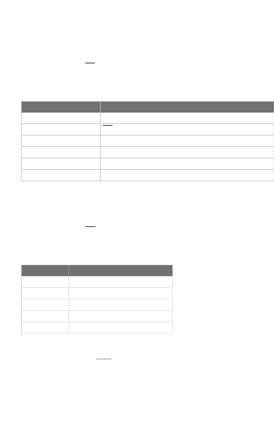
AT commands I/O settings commands
Digi XBee3 Cellular LTE Cat 1 Smart Modem User Guide 129
Default
0
D7 (DIO7/CTS)
Sets or displays the DIO7/CTS configuration (pin 12).
Parameter range
0, 1, 3 - 5
Parameter Description
0 Disabled
1CTSflow control
2 N/A
3 Digital input
4 Digital output, default low
5 Digital output, default high
Default
0x1
D8 (DIO8/SLEEP_REQUEST)
Sets or displays the DIO8/DTR/SLP_RQ configuration (pin 9).
Parameter range
0, 1, 3 - 5
Parameter Description
0 Disabled
1 SLEEP_REQUEST input
3 Digital input
4 Digital output, default low
5 Digital output, default high
Default
1
Sets or displays the DIO9/ON_SLEEP configuration (pin 13).
Parameter range
0, 1, 3 - 5

AT commands I/O settings commands
Digi XBee3 Cellular LTE Cat 1 Smart Modem User Guide 130
Parameter Description
0 Disabled
1ON/SLEEP output
3 Digital input
4 Digital output, default low
5 Digital output, default high
Default
1
P0 (DIO10/PWM0 Configuration)
Sets or displays the PWM/DIO10 configuration (pin 6).
This command enables the option of translating incoming data to a PWM so that the output can be
translated back into analog form.
Parameter range
0 - 5
Parameter Description
0 Disabled
1 RSSI PWM0 output
2 PWM0 output
3 Digital input
4 Digital output, low
5 Digital output, high
Default
0
P1 (DIO11/PWM1 Configuration)
Sets or displays the DIO11 configuration (pin 7).
Parameter range
0, 1, 3 - 6
Parameter Description
0 Disabled

AT commands I/O settings commands
Digi XBee3 Cellular LTE Cat 1 Smart Modem User Guide 131
Parameter Description
1 Fan enable. Output is low when the XBee Smart Modem is sleeping, turning an
attached fan off when the cellular component is in a power saving mode, and also
during Airplane Mode
3 Digital input
4 Digital output, default low
5 Digital output, default high
6 I2C SDA
7 USB direct
Default
0
P2 (DIO12 Configuration)
Sets or displays the DIO12 configuration (pin 4).
Parameter range
0, 1, 3 - 5
Parameter Description
0 Disabled
1 SPI_MISO
2 N/A
3 Digital input
4 Digital output, default low
5 Digital output, default high
Default
0
P3 (DIO13/DOUT)
Sets or displays the DIO13/DOUT configuration (pin 17).
Parameter range
0, 1
Parameter Description
0 Disabled
1 UART DOUT enabled

AT commands I/O settings commands
Digi XBee3 Cellular LTE Cat 1 Smart Modem User Guide 132
Default
1
P4 (DIO14/DIN)
Sets or displays the DIO14/DIN configuration (pin 3).
Parameter range
0 - 1
Parameter Description
0 Disabled
1UART DIN enabled
Default
1
PD (Pull Direction)
The resistor pull direction bit field (1= pull-up, 0= pull-down) for corresponding I/O lines that are set
by PR (Pull-up/down Resistor Enable).
If the bit is not set in PR, the device uses PD.
Note Resistors are not applied to disabled lines.
See PR (Pull-up/down Resistor Enable) for bit mappings, which are the same.
Parameter range
0x0 – 0x7FFF
Default
0 – 0x7FFF
PR (Pull-up/down Resistor Enable)
Sets or displays the bit field that configures the internal resistor status for the digital input lines.
Internal pull-up/down resistors are not available for digital output pins, analog input pins, or for
disabled pins.
Use the PD command to specify whether the resistor is pull-up or pull-down.
nIf you set a PR bit to 1, it enables the pull-up/down resistor.
nIf you set a PR bit to 0, it specifies no internal pull-up/down resistor.
The following table defines the bit-field map for both the PR and PD commands.
Bit I/O line Module pin
0 DIO4 pin 11

AT commands I/O sampling commands
Digi XBee3 Cellular LTE Cat 1 Smart Modem User Guide 133
Bit I/O line Module pin
1 DIO3/AD3 pin 17
2 DIO2/AD2 pin 18
3 DIO1/AD1 pin 19
4 DIO0/AD0 pin 20
5DIO6/RTS pin 16
6 DIO8/SLEEP_REQUEST pin 9
7DIO14/DIN pin 3
8 DIO5/ASSOCIATE pin 15
9DIO9/On/SLEEP pin 13
10 DIO12 pin 4
11 DIO10 pin 6
12 DIO11 pin 7
13 DIO7/CTS pin 12
14 DIO13/DOUT pin 17
Parameter range
0 - 0x7FFF (bit field)
Default
0x7FFF
M0 (PWM0 Duty Cycle)
Sets the duty cycle of PWM0 (pin 6) for P0 =2, where a value of 0x200 is a 50% duty cycle.
Before setting the line as an output:
1. Enable PWM0 output (P0 (DIO10/PWM0 Configuration) =2).
2. Apply the settings (use CN (Exit Command mode) or AC (Apply Changes)).
The PWM period is 42.62 µs and there are 0x03FF (1023 decimal) steps within this period. When M0 =0
(0% PWM), 0x01FF (50% PWM), 0x03FF (100% PWM), and so forth.
Parameter range
0 - 0x3FF
Default
0
I/O sampling commands
The following AT commands configure I/O sampling parameters.

AT commands I/O sampling commands
Digi XBee3 Cellular LTE Cat 1 Smart Modem User Guide 134
TP (Temperature)
Displays the temperature of the XBee Smart Modem in degrees Celsius. The temperature value is
displayed in 8-bit two’s complement format. For example, 0x1A = 26 °C, and 0xF6 = -10 °C.
Parameter range
0 - 0xFF which indicates degrees Celsius displayed in 8-bit two's complement format.
Default
N/A
IS (Force Sample)
When run, IS reports the values of all of the enabled digital and analog input lines. If no lines are
enabled for digital or analog input, the command returns an error.
Command mode
In Command mode, the response value is a multi-line format, individual lines are delimited with
carriage returns, and the entire response terminates with two carriage returns. Each line is a series of
ASCII characters representing a single number in hexadecimal notation. The interpretation of the lines
is:
nNumber of samples. For legacy reasons this field always returns 1.
nDigital channel mask. A bit-mask of all I/O capable pins in the system. The bits set to 1are
configured for digital I/O and are included in the digital data value below. Pins D0 - D9 are bits 0
- 9, and P0 - P2 are bits 10 - 12.
nAnalog channel mask. The bits set to 1are configured for analog I/O and have individual
readings following the digital data field.
nDigital data. The current digital value of all the pins set in the digital channel mask, only
present if at least one bit is set in the digital channel mask.
nAnalog data. Additional lines, one for each set pin in the analog channel mask. Each reading is a
10-bit ADC value for a 2.5 V voltage reference.
API operating mode
In API operating mode, ISimmediately returns an OK response.
The API response is ordered identical to the Command mode response with the same fields present.
Each field is a binary number of the size listed in the following table. Multi-byte fields are in big-endian
byte order.
Field Size
Number of samples 1 byte
Digital channel mask 2 bytes
Analog chanel mask 1 byte
Samples 2 bytes each

AT commands Sleep commands
Digi XBee3 Cellular LTE Cat 1 Smart Modem User Guide 135
Parameter range
N/A
Default
N/A
Sleep commands
The following AT commands are sleep commands.
SM (Sleep Mode)
Sets or displays the sleep mode of the device.
The sleep mode determines how the device enters and exits a power saving sleep.
Sleep mode is also affected by the SO command, option bit 6. See Sleep modes for more information
about sleep modes.
Parameter range
0, 1, 4, 5
Parameter Description
0 Normal. In this mode the device never sleeps.
1Pin Sleep. In this mode the device honors the SLEEP_RQ pin. Set D8 (DIO8/SLEEP_
REQUEST) to the sleep request function: 1.
4Cyclic Sleep. In this mode the device repeatedly sleeps for the value specified by SP and
spends ST time awake.
5 Cyclic Sleep with Pin Wake. In this mode the device acts as in Cyclic Sleep but does not
sleep if the SLEEP_RQ pin is inactive, allowing the device to be kept awake or woken by
the connected system.
Default
0
SP (Sleep Period)
Sets or displays the time to spend asleep in cyclic sleep modes. In Cyclic sleep mode, the node sleeps
with CTS disabled for the sleep time interval, then wakes for the wake time interval.
Parameter range
0x1 - 0x83D600 (x 10 ms)
Default
0x7530 (5 minutes)
ST (Wake Time)
Sets or displays the time to spend awake in cyclic sleep modes.

AT commands Command mode options
Digi XBee3 Cellular LTE Cat 1 Smart Modem User Guide 136
Parameter range
0x1 - 0x36EE80 (x 1 ms)
Default
0xEA60 (60 seconds)
SO (Sleep Options)
Set or read the sleep options bit field of a device. This command is a bitmask.
Parameter range
0x0 - 0xFFFF
Bit field:
Bit Setting Meaning Description
0x00 0 Connected
sleep
On compatible hardware, enters a lower power consumption mode
that maintains registration with the cellular network.
Set all other option bits to 0.
Default
0
Command mode options
The following commands are Command mode option commands.
CC (Command Sequence Character)
The character value the device uses to enter Command mode.
The default value (0x2B) is the ASCII code for the plus (+) character. You must enter it three times
within the guard time to enter Command mode. To enter Command mode, there is also a required
period of silence before and after the command sequence characters of the Command mode
sequence (GT +CC +GT). The period of silence prevents inadvertently entering Command mode.
Parameter range
0 - 0xFF
Default
0x2B (the ASCII plus character:+)
CT (Command Mode Timeout)
Sets or displays the Command mode timeout parameter. If a device does not receive any valid
commands within this time period, it returns to Idle mode from Command mode.
Parameter range
2 - 0x1770 (x 100 ms)

AT commands MicroPython commands
Digi XBee3 Cellular LTE Cat 1 Smart Modem User Guide 137
Default
0x64 (10 seconds)
CN (Exit Command mode)
Immediately exits Command Mode and applies pending changes.
Note Whether Command mode is exited using the CN command or by CT timing out, changes are
applied upon exit.
Parameter range
N/A
Default
N/A
GT (Guard Times)
Set the required period of silence before and after the command sequence characters of the
Command mode sequence (GT +CC +GT). The period of silence prevents inadvertently entering
Command mode.
Parameter range
0x2 - 0x6D3 (x 1 ms)
Default
0x3E8 (one second)
MicroPython commands
The following commands relate to using MicroPython on the XBee Smart Modem.
PS (Python Startup)
Sets whether or not the XBee Smart Modem runs the stored Python code at startup.
Range
0 - 1
Parameter Description
0 Do not run stored Python code at startup.
1 Run stored Python code at startup.
Default
0

AT commands Firmware version/information commands
Digi XBee3 Cellular LTE Cat 1 Smart Modem User Guide 138
PY (MicroPython Command)
Interact with the XBee Smart Modem using MicroPython. PY is a command with sub-commands.
These sub-commands are arguments to PY.
PYC(Code Report)
You can store compiled code in flash using the Ctrl-F command from the MicroPython REPL; refer to
the Digi MicroPython Programming Guide. The PYC sub-command reports details of the stored code. In
Command mode, it returns three lines of text, for example:
source: 1662 bytes (hash=0xC3B3A813)
bytecode: 619 bytes (hash=0x0900DBCE)
compiled: 2017-05-09T15:49:44
The messages are:
nsource: the size of the source code used to generate the bytecode and its 32-bit hash.
nbytecode:the size of bytecode stored in flash and its 32-bit hash. A size of 0indicates that
there is no stored code.
ncompiled:a compilation timestamp. A timestamp of 2000-01-01T00:00:00 indicates that the
clock was not set during compilation.
In API mode, PYC returns five 32-bit big-endian values:
nsource size
nsource hash
nbytecode size
nbytecode hash
ntimestamp as seconds since 2000-01-01T00:00:00
PYD (Delete Code)
PYDinterrupts any running code, erases any stored code and then does a soft-reboot on the
MicroPython subsystem.
PYV (Version Report)
Report the MicroPython version.
PY^ (Interrupt Program)
Sends KeyboardInterrupt to MicroPython. This is useful if there is a runaway MicroPython program
and you have filled the stdin buffer. You can enter Command mode (+++) and send ATPY^ to interrupt
the program.
Default
N/A
Firmware version/information commands
The following AT commands are firmware version/information commands.

AT commands Firmware version/information commands
Digi XBee3 Cellular LTE Cat 1 Smart Modem User Guide 139
VR (Firmware Version)
Reads the firmware version on a device.
Parameter range
0 - 0xFFFF [read-only]
Default
Set in firmware
VL (Verbose Firmware Version)
Shows detailed version information including the application build date and time.
Parameter range
N/A
Default
Set in firmware
HV (Hardware Version)
Display the hardware version number of the device.
Parameter range
0 - 0xFFFF [read-only]
Default
Set in firmware
AI (Association Indication)
Reads the Association status code to monitor association progress. The following table provides the
status codes and their meanings.
Statuscode Meaning
0x00 Connected to the Internet.
0x22 Registering to cellular network.
0x23 Connecting to the Internet.
0x24 The cellular component is missing, corrupt, or otherwise in error. The cellular
component requires a new firmware image.
0x25 Cellular network registration denied.
0x2A Airplane mode.
0x2B USB Direct active.

AT commands Diagnostic interface commands
Digi XBee3 Cellular LTE Cat 1 Smart Modem User Guide 140
Statuscode Meaning
0x2F Bypass mode active.
0xFF Initializing.
Parameter range
0 - 0xFF [read-only]
Default
N/A
HS (Hardware Series)
Read the device's hardware series number.
Parameter range
N/A
Default
Set in the firmware
CK (Configuration CRC)
Displays the cyclic redundancy check (CRC) of the current AT command configuration settings.
Parameter range
0 - 0xFFFFFFFF
Default
N/A
Diagnostic interface commands
The following AT commands are diagnostic interface commands.
DI (Remote Manager Indicator)
Displays the current Remote Manager status for the XBee.
Range
Value Description
0x00 Connected
0x01 Before connection to the Internet
0x02 Remote Manager connection in progress

AT commands Diagnostic interface commands
Digi XBee3 Cellular LTE Cat 1 Smart Modem User Guide 141
Value Description
0x03 Disconnecting from Remote Manager
0x04 Not configured for Remote Manager
Default
N/A
CI (Protocol/Connection Indication)
Displays information regarding the last IP connection (when the IP command = 0,1or 4) or SMS
transmission (when IP =2).
The value for this parameter resets to 0xFF when the device switches between IP (IP Protocol)
modes.
When IP is set to 0,1, or 4(UDP, TCP, over SSL over TCP), CI resets to 0xFF when you apply changes to
any of the following settings:
nDL (Destination Address)
nDE (Destination Port)
nTM (IP Client Connection Timeout)
When IP is set to 2(SMS), CI resets to 0xFF when P# (Destination Phone Number) is changed.
The following table provides the parameter's meaning when IP =0for UDP connections.
Parameter Description
0x00 The socket is open.
0x01 Tried to send but could not.
0x02 Invalid parameters (bad IP/host).
0x03 TCP not supported on this cellular component.
0x10 Not registered to the cell network.
0x11 Cellular component not identified yet.
0x12 DNS query lookup failure.
0x13 Socket leak
0x20 Bad handle.
0x21 User closed.
0x22 Unknown server - DNS lookup failed.
0x23 Connection lost.
0x24 Unknown.
0xFF No known status.
The following table provides the parameter's meaning when IP =1or 4for TCP connections.

AT commands Diagnostic interface commands
Digi XBee3 Cellular LTE Cat 1 Smart Modem User Guide 142
Parameter Description
0x00 The socket is open.
0x01 Tried to send but could not.
0x02 Invalid parameters (bad IP/host).
0x03 TCP not supported on this cellular component.
0x10 Not registered to the cell network.
0x11 Cellular component not identified yet.
0x12 DNS query lookup failure.
0x13 Socket leak
0x20 Bad handle.
0x21 User closed.
0x22 No network registration.
0x23 No internet connection.
0x24 No server - timed out on connection.
0x25 Unknown server - DNS lookup failed.
0x26 Connection refused.
0x27 Connection lost.
0x28 Unknown.
0xFF No known status.
The following table provides the parameter's meaning when IP =2for SMS connections.
Parameter Description
0x00 SMS successfully sent.
0x01 SMS failed to send.
0x02 Invalid SMS parameters - check P# (Destination Phone Number).
0x03 SMS not supported.
0x10 No network registration.
0x11 Cellular component stack error.
0x13 Socket leak
0xFF No SMS state to report (no SMS messages have been sent).
Parameter range
0 - 0xFF (read-only)
AT commands Execution commands
Digi XBee3 Cellular LTE Cat 1 Smart Modem User Guide 143
Default
-
Execution commands
The location where most AT commands set or query register values, execution commands execute an
action on the device. Execution commands are executed immediately and do not require changes to
be applied.
NR (Network Reset)
NR resets the network layer parameters.
The XBee Smart Modem responds immediately with an OK on the UART and then causes a network
restart.
If NR =0, the XBee Smart Modem tears down any TCP/UDP sockets and resets Internet connectivity.
You can also send NR, which acts like NR =0.
Parameter range
0
Default
N/A
!R (Modem Reset)
Forces the cellular component to reboot.
CAUTION! This command is for advanced users, and you should only use it if the cellular
component becomes completely stuck while in Bypass mode. Normal users should never
need to run this command. See the FR (Force Reset) command instead.
Range
N/A
Default
N/A
File system commands
To access the file system, Enter Command mode and use the following commands. All commands
block the AT command processor until completed and only work from Command mode; they are not
valid for API mode or MicroPython's xbee.atcmd() method. Commands are case-insensitive as are file
and directory names. Optional parameters are shown in square brackets ([]).
FS is a command with sub-commands. These sub-commands are arguments to FS.
For FS commands, you have to type AT before the command, for example ATFS PWD,ATFS LS and so
forth.

AT commands File system commands
Digi XBee3 Cellular LTE Cat 1 Smart Modem User Guide 144
Error responses
If a command succeeds it returns information such as the name of the current working directory or a
list of files, orOKif there is no information to report. If it fails, you see a detailed error message
instead of the typicalERROR response for a failing ATcommand.The response is a named error code
and a textual description of the error.
Note The exact content of error messages may change in the future. All errors start with a capital E,
followed by one or more uppercase letters and digits, a space, and an description of the error.
If writing your own AT command parsing code, you can determine if an FS command response is an
error by checking if the first letter of the response is capital E.
ATFS (File System)
When sent without any parameters, FS prints a list of supported commands.
ATFS PWD
Prints the current working directory, which always starts with/and defaults to/flashat startup.
ATFS CDdirectory
Changes the current working directory todirectory. Prints the current working directory or an error
if unable to change todirectory.
ATFS MDdirectory
Creates the directorydirectory. PrintsOKif successful or an error if unable to create the requested
directory.
ATFS LS [directory]
Lists files and directories in the specified directory. Thedirectoryparameter is optional and defaults
to a period(.), which represents the current directory. The list ends with a blank line.
Entries start with zero or more spaces, followed by filesize or the string<DIR>for directories, then a
single space character and the name of the entry. Directory names end with a forward slash (/) to
differentiate them from files. Secure files end with a hash mark (#) and you cannot download them.
<DIR> ./
<DIR> ../
<DIR> cert/
<DIR> lib/
32 test.txt
1234 secure.bin#
ATFS PUTfilename
Starts a YMODEM receive on the XBee Smart Modem, storing the received file tofilenameand ignoring
the filename that appears in block 0 of the YMODEM transfer. The XBee Smart Modem sends a
prompt (Receivingfile with YMODEM...)when it is ready to receive, at which point you should initiate
a YMODEM send in your terminal emulator.
If the command is incorrect, the reply will be an error as described in Error responses.

AT commands File system commands
Digi XBee3 Cellular LTE Cat 1 Smart Modem User Guide 145
ATFS XPUTfilename
Similar to thePUTcommand, but stores the file securely on the XBee Smart Modem. See Secure files
for details on what this means.
If the command is incorrect, the reply will be an error as described in Error responses.
ATFS HASHfilename
Print a sha256 hash of a secure file uploaded via the XPUTcommand to allow for verification against a
local copy of the file. On Windows, you can generate a SHA256 hash of a file with the
commandcertutil -hashfile test.txt SHA256.On Mac and Linux useshasum -b -a 256 test.txt.
ATFS GETfilename
Starts a YMODEM send offilenameon the XBee device.When it is ready to send, the XBee Smart
Modem sends a prompt:(Sendingfile with YMODEM...). When the prompt is sent, you should initiate
a YMODEM receive in your terminal emulator.
If the command is incorrect, the reply will be an error as described in Error responses.
ATFS MVsource_pathdest_path
Moves or renames the selected file or directorysource_pathto the new name or locationdest_
path.This commandfails with an error ifsource_pathdoes not exist, ordest_pathalready exists.
Note Unlike a computer's command prompt which moves a file into the dest_path if it is an existing
directory, you must specify the full name for dest_path.
ATFS RMfile_or_directory
Removes the file or empty directory specified byfile_or_directory.This command fails with an error
iffile_or_directorydoes not exist, is not empty, refers to the current working directory or one of its
parents.
ATFS INFO
Report on the size of the filesystem, showing bytes in use, available, marked bad and total.The report
ends with a blank line, as with most multi-line AT command output. Example output:
204800 used
695296 free
0 bad
900096 total
ATFSFORMAT confirm
Reformats the file system, leaving it with a default directory structure.Pass the word confirm as the
first parameter to confirm the format. The XBee Smart Modem responds withFormatting..., adds a
period every second until the format is complete and ends the response with a carriage return.


Operate in API mode API mode overview
Digi XBee3 Cellular LTE Cat 1 Smart Modem User Guide 147
API mode overview
As an alternative to Transparent operating mode, you can use API operating mode. API mode provides
a structured interface where data is communicated through the serial interface in organized packets
and in a determined order. This enables you to establish complex communication between devices
without having to define your own protocol. The API specifies how commands, command responses
and device status messages are sent and received from the device using the serial interface or the
SPIinterface.
We may add new frame types to future versions of firmware, so build the ability to filter out additional
API frames with unknown frame types into your software interface.
Use the AP command to set the operation mode
Use AP (API Enable) to specify the operation mode:
AP command
setting Description
AP = 0 Transparent operating mode, UARTserial line replacement with API modes
disabled. This is the default option.
AP = 1 API operation.
AP = 2 API operation with escaped characters (only possible on UART).
AP = 3 N/A
AP = 4 MicroPython REPL
AP = 5 Bypass mode. This mode is for direct communication with the underlying chip and
is only for advanced users.
The API data frame structure differs depending on what mode you choose.
API frame format
An API frame consists of the following:
nStart delimeter
nLength
nFrame data
nChecksum
API operation (AP parameter = 1)
This is the recommended API mode for most applications. The following table shows the data frame
structure when you enable this mode:

Operate in API mode API frame format
Digi XBee3 Cellular LTE Cat 1 Smart Modem User Guide 148
Frame fields Byte Description
Start delimiter 1 0x7E
Length 2 - 3 Most Significant Byte, Least Significant Byte
Frame data 4 - number (n) API-specific structure
Checksum n + 1 1 byte
Any data received prior to the start delimiter is silently discarded. If the frame is not received correctly
or if the checksum fails, the XBee replies with a radio status frame indicating the reason for the
failure.
API operation with escaped characters (AP parameter = 2)
Setting API to 2 allows escaped control characters in the API frame. Due to its increased complexity,
we only recommend this API mode in specific circumstances. API 2 may help improve reliability if the
serial interface to the device is unstable or malformed frames are frequently being generated.
When operating in API 2, if an unescaped 0x7E byte is observed, it is treated as the start of a new API
frame and all data received prior to this delimiter is silently discarded. For more information on using
this API mode, see the Escaped Characters and API Mode 2 in the Digi Knowledge base.
API escaped operating mode works similarly to API mode. The only difference is that when working in
API escaped mode, the software must escape any payload bytes that match API frame specific data,
such as the start-of-frame byte (0x7E). The following table shows the structure of an API frame with
escaped characters:
Frame fields Byte Description
Start delimiter 1 0x7E
Length 2 - 3 Most Significant Byte, Least Significant Byte Characters escaped if needed
Frame data 4 - n API-specific structure
Checksum n + 1 1 byte
Start delimiter field
This field indicates the beginning of a frame. It is always 0x7E. This allows the device to easily detect a
new incoming frame.
Escaped characters in API frames
If operating in API mode with escaped characters (AP parameter = 2), when sending or receiving a
serial data frame, specific data values must be escaped (flagged) so they do not interfere with the
data frame sequencing. To escape an interfering data byte, insert 0x7D and follow it with the byte to
be escaped (XORed with 0x20).
The following data bytes need to be escaped:
n0x7E: start delimiter
n0x7D: escape character
n0x11: XON
n0x13: XOFF

Operate in API mode API frame format
Digi XBee3 Cellular LTE Cat 1 Smart Modem User Guide 149
To escape a character:
1. Insert 0x7D (escape character).
2. Append it with the byte you want to escape, XORed with 0x20.
In API mode with escaped characters, the length field does not include any escape characters in the
frame and the firmware calculates the checksum with non-escaped data.
Example: escape an API frame
To express the following API non-escaped frame in API operating mode with escaped characters:
Start delimiter Length Frame type Frame Data Checksum
Data
7E 00 0F 17 01 00 13 A2 00 40 AD 14 2E FF FE 02 4E 49 6D
You must escape the 0x13 byte:
1. Insert a 0x7D.
2. XOR byte 0x13 with 0x20: 13 ⊕20 = 33
The following figure shows the resulting frame. Note that the length and checksum are the same as
the non-escaped frame.
Start delimiter Length Frame type Frame Data Checksum
Data
7E 00 0F 17 01 00 7D 33 A2 00 40 AD 14 2E FF FE 02 4E 49 6D
The length field has a two-byte value that specifies the number of bytes in the frame data field. It does
not include the checksum field.
Length field
The length field is a two-byte value that specifies the number of bytes contained in the frame data
field. It does not include the checksum field.
Frame data
This field contains the information that a device receives or will transmit. The structure of frame data
depends on the purpose of the API frame:
Length
Frame data
Data
1 2 3 4 5 6 7 8 9 ... n n+1
0x7E MSB LSB Data
nFrame type is the API frame type identifier. It determines the type of API frame and indicates
how the Data field organizes the information.
nData contains the data itself. This information and its order depend on the what type of frame
that the Frame type field defines.
Multi-byte values are sent big-endian.

Operate in API mode API frame format
Digi XBee3 Cellular LTE Cat 1 Smart Modem User Guide 150
Calculate and verify checksums
To calculate the checksum of an API frame:
1. Add all bytes of the packet, except the start delimiter 0x7E and the length (the second and
third bytes).
2. Keep only the lowest 8 bits from the result.
3. Subtract this quantity from 0xFF.
To verify the checksum of an API frame:
1. Add all bytes including the checksum; do not include the delimiter and length.
2. If the checksum is correct, the last two digits on the far right of the sum equal 0xFF.
Example
Consider the following sample data packet: 7E 00 0A 01 01 50 01 00 48 65 6C 6C 6F B8+
Byte(s) Description
7E Start delimiter
00 0A Length bytes
01 API identifier
01 API frame ID
50 01 Destination address low
00 Option byte
48 65 6C 6C 6F Data packet
B8 Checksum
To calculate the check sum you add all bytes of the packet, excluding the frame delimiter 7E and the
length (the second and third bytes):
7E 00 0A 01 01 50 01 00 48 65 6C 6C 6F B8
Add these hex bytes:
01 + 01 + 50 + 01 + 00 + 48 + 65 + 6C + 6C + 6F = 247
Now take the result of 0x247 and keep only the lowest 8 bits which in this example is 0xC4 (the two
far right digits). Subtract 0x47 from 0xFF and you get 0x3B (0xFF - 0xC4 = 0x3B). 0x3B is the checksum
for this data packet.
If an API data packet is composed with an incorrect checksum, the XBee Smart Modem will consider
the packet invalid and will ignore the data.
To verify the check sum of an API packet add all bytes including the checksum (do not include the
delimiter and length) and if correct, the last two far right digits of the sum will equal FF.
01 + 01 + 50 + 01 + 00 + 48 + 65 + 6C + 6C + 6F + B8 = 2FF

API frames
The following sections describe the API frames.
AT Command - 0x08 152
Transmit (TX) SMS - 0x1F 153
Transmit (TX) Request: IPv4 - 0x20 154
Tx Request with TLS Profile - 0x23 156
AT Command Response - 0x88 158
Transmit (TX) Status - 0x89 159
Modem Status - 0x8A 161
Receive (RX) Packet: SMS - 0x9F 162
Receive (RX) Packet: IPv4 - 0xB0 163
Digi XBee3 Cellular LTE Cat 1 Smart Modem User Guide 151

API frames AT Command - 0x08
Digi XBee3 Cellular LTE Cat 1 Smart Modem User Guide 152
AT Command - 0x08
Description
Use this frame to query or set parameters on the local device. Changes this frame makes to device
parameters take effect after executing the AT command.
Format
The following table provides the contents of the frame. For details on frame structure, see API frame
format.
Field
name
Field
value
Data
type Description
Frame
type
0x08 Byte
Frame ID Byte Identifies the data frame for the host to correlate with a subsequent
ACK. If set to 0, the device does not send a response.
AT
command
Byte Command name: two ASCII characters that identify the AT command.
Parameter
value
Byte If present, indicates the requested parameter value to set the given
register. If no characters are present, it queries the register.

API frames Transmit (TX) SMS - 0x1F
Digi XBee3 Cellular LTE Cat 1 Smart Modem User Guide 153
Transmit (TX) SMS - 0x1F
Description
Transmit an SMS message. The frame allows international numbers with or without the +prefix. If you
omit +and are dialing internationally, you need to include the proper International Dialing Prefix for
your calling region, for example, 011 for the United States.
Format
The following table provides the contents of the frame. For details on frame structure, see API frame
format.
Field
name Fieldvalue Data type Description
Frametype 0x1F Byte
Frame ID Byte Reference identifier used to match status responses. 0
disables the TX Status frame.
Options Byte Reserved for future use.
Phone
number
20 byte string String representation of phone number terminated
with a null (0x0) byte. Use numbers and the +symbol
only, no other symbols or letters.
Payload Variable
(160characters
maximum)
Data to send as the body of the SMS message.

API frames Transmit (TX) Request: IPv4 - 0x20
Digi XBee3 Cellular LTE Cat 1 Smart Modem User Guide 154
Transmit (TX) Request: IPv4 - 0x20
Description
A TX Request message causes the device to transmit data in IPv4 format. A TX request frame for a
new destination creates a network socket. After the network socket is established, data from the
network that is received on the socket is sent out the device's serial port in the form of a Receive (RX)
Packet frame.
Format
The following table provides the contents of the frame. For details on frame structure, see API frame
format.
Field name
Field
value Data type Description
Frame type 0x20 Byte
Frame ID Byte Reference identifier used to match status responses. 0
disables the TX Status frame.
Destination
address
32-bit big
endian
Destination port 16-bit
bigendian
Source port 16-bit
bigendian
If the source port is 0, the device attempts to send the frame
data using an existing open socket with a destination that
matches the destination address and destination port fields
of this frame. If there is no matching socket, then the device
attempts to open a new socket.
If the source port is non-zero, the device attempts to send
the frame data using an existing open socket with a source
and destination that matches the source port, destination
address, and destination port fields of this frame. If there is
no matching socket, it returns an error.
Protocol Byte 0 = UDP
1 = TCP
4 = SSL over TCP
Transmitoptions Byte
bitfield
Bit fields are offset 0
Bit field 0 - 7. Bits 0, and 2-7 are reserved, bit 1 is not.
BIT 1 =
1- Terminate the TCP socket after transmission is complete
0- Leave the socket open. Closed by timeout, see TM (IP
Client Connection Timeout).
Ignore this bit for UDP packets.
All other bits are reserved and should be 0.

API frames Transmit (TX) Request: IPv4 - 0x20
Digi XBee3 Cellular LTE Cat 1 Smart Modem User Guide 155
Field name
Field
value Data type Description
Payload Variable Data to be transferred to the destination, may be up to 1500
bytes.

API frames Tx Request with TLS Profile - 0x23
Digi XBee3 Cellular LTE Cat 1 Smart Modem User Guide 156
Tx Request with TLS Profile - 0x23
Description
The frame gives greater control to the application over the TLS settings used for a connection.
A TX Request with TLS Profile frame implies the use of TLS and behaves similar to the TX Request
(0x20) frame, with the protocol field replaced with a TLS Profile field to choose from the profiles
configured with the $0, $1, and $2 configuration commands.
Format
The following table provides the contents of the frame. For details on frame structure, see API frame
format.
Field name
Field
value Data type Description
Frame type 0x23 Byte
Frame ID Byte Reference identifier used to match status responses. 0
disables the TX Status frame.
Destination
address
32-bit big
endian
Destination port 16-bit
bigendian
Source port 16-bit
bigendian
If the source port is 0, the device attempts to send the frame
data using an existing open socket with a destination that
matches the destination address and destination port fields
of this frame. If there is no matching socket, then the device
attempts to open a new socket.
If the source port is non-zero, the device attempts to send
the frame data using an existing open socket with a source
and destination that matches the source port, destination
address, and destination port fields of this frame. If there is
no matching socket, the TX Status frame returns an error.
TLS profile Byte Zero-indexed number that indicates the profile as specified
by the corresponding $<num>command.
Transmitoptions Byte
bitfield
Bit fields are offset 0
Bit field 0 - 7. Bits 0, and 2-7 are reserved, bit 1 is not.
BIT 1 =
1- Terminate the TCP socket after transmission is complete
0- Leave the socket open. Closed by timeout, see TM (IP
Client Connection Timeout).
Ignore this bit for UDP packets.
All other bits are reserved and should be 0.

API frames Tx Request with TLS Profile - 0x23
Digi XBee3 Cellular LTE Cat 1 Smart Modem User Guide 157
Field name
Field
value Data type Description
Payload Variable Data to be transferred to the destination, may be up to 1500
bytes.

API frames AT Command Response - 0x88
Digi XBee3 Cellular LTE Cat 1 Smart Modem User Guide 158
AT Command Response - 0x88
Description
A device sends this frame in response to an AT Command (0x08) frame. Some commands send back
multiple frames.
Format
The following table provides the contents of the frame. For details on frame structure, see API frame
format.
Field
name
Field
value
Data
type Description
Frame
type
0x88 Byte
Frame ID Byte Identifies the data frame for the host to correlate with a subsequent
ACK. If set to 0, the device does not send a response.
AT
command
Byte Command name: two ASCII characters that identify the AT command.
Status ## Byte 0 = OK
1 = ERROR
2 = Invalid command
3 = Invalid parameter
Parameter
value
Byte Register data in binary format. If the register was set, then this field is
not returned.

API frames Transmit (TX) Status - 0x89
Digi XBee3 Cellular LTE Cat 1 Smart Modem User Guide 159
Transmit (TX) Status - 0x89
Description
Indicates the success or failure of a transmit operation.
Format
The following table provides the contents of the frame. For details on frame structure, see API frame
format.
Field name Field value Data type Description
Frametype 0x89 Byte
Frame ID Byte Refers to the frame ID specified in a previous transmit
frame
Status Byte Status code (see the table below)
The following table shows the status codes.
Code Description
0x0 Successful transmit
0x21 Failure to transmit to cell network
0x22 Not registered to cell network
0x2c Invalid frame values (check the phone number)
0x31 Internal error
0x32 Resource error (retry operation later)
0x74 Message too long
0x78 Invalid UDP port
0x79 Invalid TCP port
0x7A Invalid host address
0x7B Invalid data mode
0x80 Connection refused
0x81 Socket connection lost
0x82 No server
0x83 Socket closed

API frames Transmit (TX) Status - 0x89
Digi XBee3 Cellular LTE Cat 1 Smart Modem User Guide 160
Code Description
0x84 Unknown server
0x85 Unknown error
0x86 Invalid TLS configuration (missing file, and so forth)

API frames Modem Status - 0x8A
Digi XBee3 Cellular LTE Cat 1 Smart Modem User Guide 161
Modem Status - 0x8A
Description
Cellular component status messages are sent from the device in response to specific conditions.
Format
The following table provides the contents of the frame. For details on frame structure, see API frame
format.
Field name Field value Data type Description
Frame type 0x8A Byte
Status ## Byte 0 = Hardware reset or power up
1 = Watchdog timer reset
2 = Registered with cellular network
3 = Unregistered with cellular network
0x0E = Remote Manager connected
0x0F = Remote Manager disconnected

API frames Receive (RX) Packet: SMS - 0x9F
Digi XBee3 Cellular LTE Cat 1 Smart Modem User Guide 162
Receive (RX) Packet: SMS - 0x9F
Description
This XBee Smart Modem uses this frame when it receives an SMS message.
Format
The following table provides the contents of the frame. For details on frame structure, see API frame
format.
Field
name
Field
value Data type Description
Frame
Type
0x9F Byte
Phone
number
20 byte
string
String representation of the phone number, padded out with
null bytes (0x0).
Payload Variable Body of the received SMS message.

API frames Receive (RX) Packet: IPv4 - 0xB0
Digi XBee3 Cellular LTE Cat 1 Smart Modem User Guide 163
Receive (RX) Packet: IPv4 - 0xB0
Description
The XBee Smart Modem uses this frame when it receives RF data on a network socket that is created
by a TX request frame or configuring C0 (Source Port).
Format
The following table provides the contents of the frame. For details on frame structure, see API frame
format.
Framedatafields Offset Description
Frame type 3 0xB0
IPv4 32-bit source
address
MSB 4 The address in the example below is for a source address of
192.168.0.104.
32-bit big endian.
5
6
7
16-bit destination port MSB 8 The port that the packet was received on.
16-bit big endian.
LSB 9
16-bit source port MSB10 The port that the packet was sent from.
16-bit big endian.
LSB 11
Protocol MSB 12 0 = UDP
1 = TCP
4 = SSL over TCP
Status 13 Reserved
Payload 14 Data received from the source. The maximum size is 1500 bytes.
15
16
17
18

Configure the XBee Smart Modem using Digi Remote
Manager
Use Digi Remote Manager (https://remotemanager.digi.com/) to perform the operations in this
section. Each operation requires that you enable Remote Manager with the DO command and that
you connect the XBee Smart Modem to an access point that has an external Internet connection to
allow access to Digi Remote Manager.
Note Digi is consolidating our cloud services, Digi Device Cloud and Digi Remote Manager®, under the
Remote Manager name. This phased process does not affect device functionality or the functionality
of the web services and other features. However, customers will find that some user interface and
firmware functionality mention both Device Cloud and Digi Remote Manager.
Create a Remote Manager account 165
Get the XBee Smart Modem IMEI number 165
Add a XBee Smart Modem to Remote Manager 165
Update the firmware 166
Update the firmware using web services 166
Digi XBee3 Cellular LTE Cat 1 Smart Modem User Guide 164
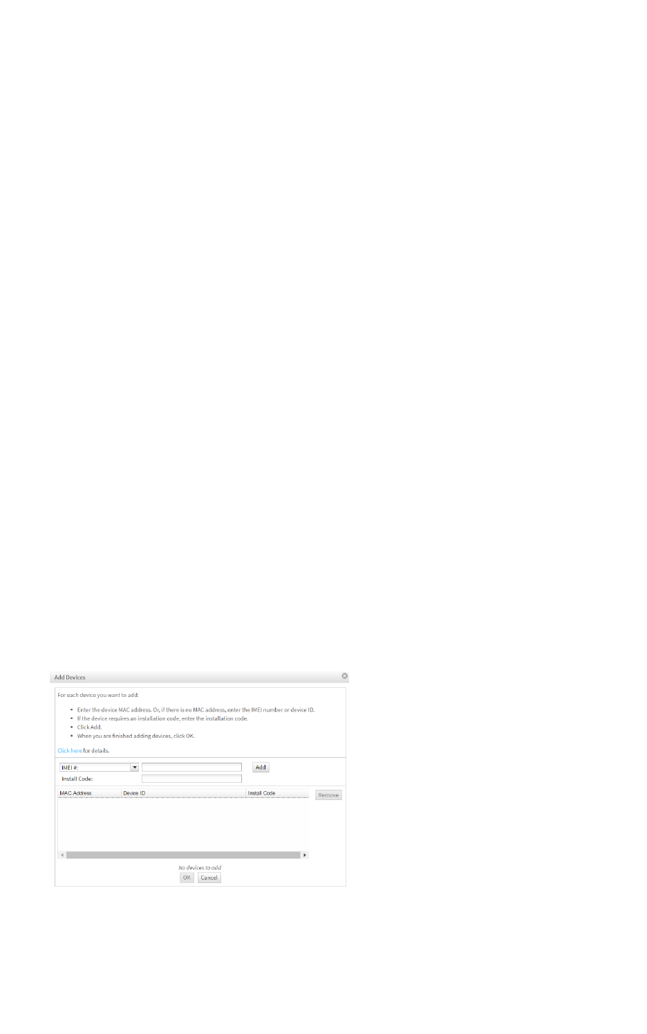
Configure the XBee Smart Modem using Digi Remote Manager Create a Remote Manager account
Digi XBee3 Cellular LTE Cat 1 Smart Modem User Guide 165
Create a Remote Manager account
Digi Remote Manager is an on-demand service with no infrastructure requirements. Remote devices
and enterprise business applications connect to Remote Manager through standards-based web
services. This section describes how to configure and manage an XBee using Remote Manager. For
detailed information on using Remote Manager, refer to the Remote Manager User Guide, available
via the Documentation tab in Remote Manager.
Before you can manage an XBee with Remote Manager, you must create a Remote Manager account.
To create a Remote Manager account:
1. Go to https://www.digi.com/products/cloud/digi-remote-manager.
2. Click 30 DAYFREETRIAL/LOGIN.
3. Follow the online instructions to complete account registration. You can upgrade your
Developer account to a paid account at any time.
When you are ready to deploy multiple XBee Smart Modems in the field, upgrade your account to
access additional Remote Manager features.
Get the XBee Smart Modem IMEI number
Before adding an XBee to your Remote Manager account inventory, you need to determine the
International Mobile Equipment Identity (IMEI) number for the device. Use XCTUto view the IMEI
number by querying the IM parameter.
Add a XBee Smart Modem to Remote Manager
To add an XBee to your Remote Manager account inventory, follow these steps:
Go to https://remotemanager.digi.com/.
1. Log in to your account.
2. Click Device Management >Devices.
3. Click Add Devices. The Add Devices dialog appears.
4. Select IMEI#, and type or paste the IMEI number of the XBee you want to add. The IM
(IMEI)command provides this number.
5. Click Add to add the device. The XBee is added to your inventory.
6. Click OK to close the Add Devices dialog and return to the Devices view.

Configure the XBee Smart Modem using Digi Remote Manager Update the firmware
Digi XBee3 Cellular LTE Cat 1 Smart Modem User Guide 166
Update the firmware
XBee Smart Modem supports Remote Manager firmware updates. To perform a firmware update:
1. Download the updated firmware file for your device from Digi's support site. This is a zip file
containing .ebin and .mxi files for import.
2. Unzip the file.
3. In your Remote Manager account, click Device Management > Devices.
4. Select the first device you want to update.
5. To select multiple devices (must be of the same type), press the Control key and select
additional devices.
6. Click More in the Devices toolbar and select Update Firmware from the Update category of
the More menu. The Update Firmware dialog appears.
7. Click Browse to select the .ebin file that you unzipped earlier.
8. Click Update Firmware. The updated devices automatically reboot when the updates are
complete.
Update the firmware using web services
Remote Manager supports both synchronous and asynchronous firmware update using web services.
The following examples show how to perform an asynchronous firmware update. See the Remote
Manager documentation for more details on firmware updates.
Note You must use XCTU to update the cellular component's firmware.
1. Download the updated firmware file for your device from Digi's support site. This is a zip file
containing .ebin and .mxi files for import.
2. Unzip the file and locate the .ebin inside the unzipped directory.
3. Send an HTTP SCI request to Remote Manager with the contents of the .ebin file converted to
base64 data; see the following example.
Example: update the XBee firmware synchronously with Python 3.0
import base64
import requests
# Location of firmware image
firmware_path = 'XBXC.ebin'
# Remote Manager device ID of the device being updated
device_id = '00010000-00000000-03526130-70153378'
# Remote Manager username and password
username = "my_Remote_manager_username"
password = "my_remote_manager_password"
url = 'https://remotemanager.digi.com/ws/sci'

Configure the XBee Smart Modem using Digi Remote Manager Update the firmware using web services
Digi XBee3 Cellular LTE Cat 1 Smart Modem User Guide 167
# Get firmware image
fw_file = open(firmware_path, 'rb')
fw_data = fw_file.read()
fw_data = base64.encodebytes(fw_data).decode('utf-8')
# Form update_firmware request
data = """
<sci_request version="1.0">
<update_firmware filename="firmware.ebin">
<targets>
<device id="{}"/>
</targets>
<data>{}</data>
</update_firmware>
</sci_request>
""".format(device_id, fw_data)
# Post request
r = requests.post(url, auth=(username, password), data=data)
if (r.status_code != 200) or ("error" in r.content.decode('utf-8')):
print("firmware update failed")
else:
print("firmware update success")
Example: use the device's firmware image to update the XBee
firmware synchronously
To update the XBee firmware synchronously with Python 3.0, but using the device firmware image
already uploaded to Remote Manager, upload the device's *.ebin firmware to Remote Manager:
1. Download the updated firmware file for your device from Digi's support site. This is a zip file
containing .ebin and .mxi files for import.
2. Unzip the file and locate the .ebin inside the unzipped directory.
3. Log in to Remote Manager.
4. Click the Data Services tab.
5. Click Data Files.
6. Click Upload Files; browse and select the *.ebin firmware file to upload it.
7. Send an HTTP SCI request to Remote manager with the path of the .ebin file; see the example
below.
import base64
import requests
# Location of firmware image on Remote Manager
firmware_path = '~/XBXC.ebin'
# Remote Manager device ID of the device being updated
device_id = '00010000-00000000-03526130-70153378'
# Remote Manager username and password
username = "my_remote_manager_username"
password = "my_remote_manager_password"

Configure the XBee Smart Modem using Digi Remote Manager Update the firmware using web services
Digi XBee3 Cellular LTE Cat 1 Smart Modem User Guide 168
url = 'https://remotemanager.digi.com/ws/sci'
# Form update_firmware request
data = """
<sci_request version="1.0">
<update_firmware filename="firmware.ebin">
<targets>
<device id="{}"/>
</targets>
<file>{}</file>
</update_firmware>
</sci_request>
""".format(device_id, firmware_path)
# Post request
r = requests.post(url, auth=(username, password), data=data)
if (r.status_code != 200) or ("error" in r.content.decode('utf-8')):
print("firmware update failed")
else:
print("firmware update success")

Troubleshooting
This section contains troubleshooting steps for the XBee Smart Modem.
Cannot find the serial port for the device 170
Correct a macOS Java error 172
Unresponsive cellular component in Bypass mode 173
Not on expected network after APN change 174
Syntax error at line 1 174
Error Failed to send SMS 174
Digi XBee3 Cellular LTE Cat 1 Smart Modem User Guide 169
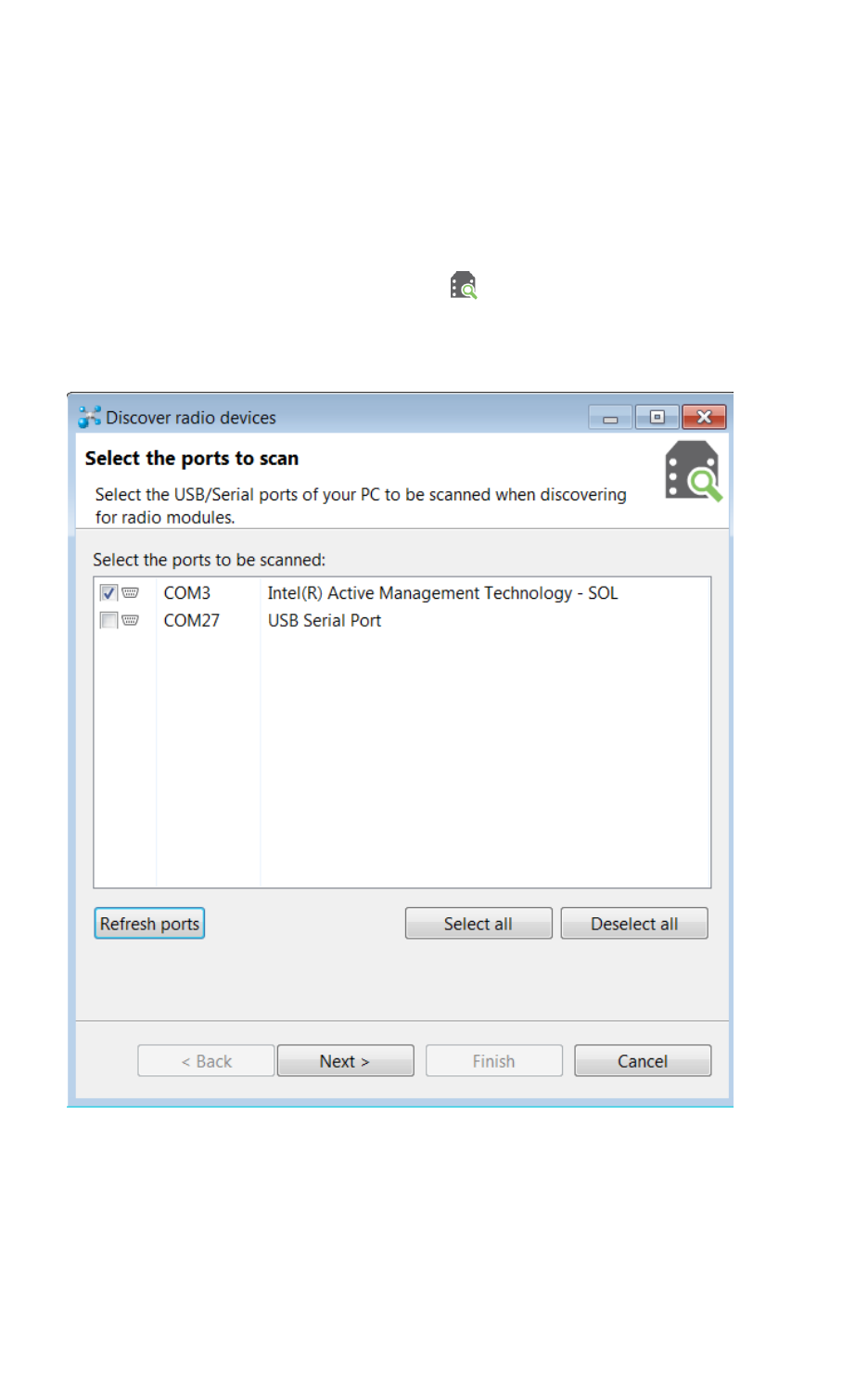
Troubleshooting Cannot find the serial port for the device
Digi XBee3 Cellular LTE Cat 1 Smart Modem User Guide 170
Cannot find the serial port for the device
Condition
In XCTU, the serial port that your device is connected to does not appear.
Solution
1. Click the Discover radio modules button .
2. Select all of the ports to be scanned.
3. Click Next and then Finish. A dialog notifies you of the devices discovered and their details.
4. Remove the development board from the USB port and view which port name no longer
appears in the Discover radio devices list of ports. The port name that no longer appears is
the correct port for the development board.

Troubleshooting Cannot find the serial port for the device
Digi XBee3 Cellular LTE Cat 1 Smart Modem User Guide 171
Other possible issues
Other reasons that the XBee Smart Modem is not discoverable include:
1. If you accidentally have the loopback pins jumpered.
2. You may not have a driver installed. If you do not have a driver installed, the item will have an
exclamation point icon next to it in the Windows Device Manager.
3. You may not be using an updated FTDI driver.
a. Click here to download the drivers for your operating system.
b. This may require you to reboot your computer.
c. Disconnect the power and USB from the XBIB-U-DEV board and reconnect it.
4. If you have a driver installed and updated but still have issues, on Windows 10 you may have to
enable VCP on the driver; see Enable Virtual COM port (VCP) on the driver.
Enable Virtual COM port (VCP) on the driver
On Windows 10 computers, if XCTU does not see the devices you have attached to a PC, you may need
to enable VCP on the USB driver.
To enable VCP:
1. Click the Search button.
2. Type Device Manager to search for it.
3. Click Universal Serial Bus controllers.
4. If it displays more than one USB controller, unplug the XBee Smart Modem and plug it back in
to make sure you choose the correct one.
5. Right-click the USB controller and select Properties; a dialog displays.
6. Select the Advanced tab.
7. Check Load VCP.
8. Click OK.
9. Unplug the board and plug it back in.
Troubleshooting Correct a macOS Java error
Digi XBee3 Cellular LTE Cat 1 Smart Modem User Guide 172
Correct a macOS Java error
When you use XCTU on macOS computer, you may encounter a Java error.
Condition
When opening XCTU for the first time on a macOS computer, you may see the following error:
Solution
1. Click More info to open a browser window.
2. Click Download to get the file javaforosx.dmg.
3. Double-click on the downloaded javaforosx.dmg.
4. In the dialog, double-click the JavaForOSX.pkg and follow the instructions to install Java.

Troubleshooting Unresponsive cellular component in Bypass mode
Digi XBee3 Cellular LTE Cat 1 Smart Modem User Guide 173
Unresponsive cellular component in Bypass mode
When in Bypass mode, the XBee Smart Modem does not automatically reset or reboot the cellular
component if it becomes unresponsive.
Condition
In Bypass mode, the XBee Smart Modem does not respond to commands.
Solution
1. Query the AI (Association Indication) parameter to determine whether the cellular component
is connected to the XBee Smart Modem software. If AIis 0x2F, Bypass mode should work. If
not, look at the status codes in AI (Association Indication) for guidance.
2. You can send the !R (Modem Reset) command to reset only the cellular component.

Troubleshooting Not on expected network after APN change
Digi XBee3 Cellular LTE Cat 1 Smart Modem User Guide 174
Not on expected network after APN change
Condition
The XBee Smart Modem is not on the expected network after a change to the AN (Access Point Name)
command.
Solution
Send ATNR0 to reset Internet connectivity. See NR (Network Reset) for more information.
Syntax error at line 1
You may get a syntax error at line 1 error after pasting example MicroPython code and pressing
Ctrl+D.
Solution
This commonly happens when you accidentally type a character at the beginning of line 1 before
pasting the code.
Error Failed to send SMS
In MicroPython, you consistently get Error Failed to send SMS messages.
Solution
Your device cannot connect to the cell network. The reason may be:
1. The antenna is improperly or loosely connected.
2. The device is at a location where cellular service cannot reach. If the device is connected to the
network, the red LED blinks about twice in a second. If it is not connected it does not blink; see
The Associate LED.
3. You SIMcard is out of SMS text quota.
4. The device is not getting enough current, for example if power is being supplied only by USB to
the XBIB development board, rather than using an additional external power supply.


Regulatory information Modification statement
Digi XBee3 Cellular LTE Cat 1 Smart Modem User Guide 176
Modification statement
Digi International has not approved any changes or modifications to this device by the user. Any
changes or modifications could void the user’s authority to operate the equipment.
Digi International n’approuve aucune modification apportée à l’appareil par l’utilisateur, quelle qu’en soit
la nature. Tout changement ou modification peuvent annuler le droit d’utilisation de l’appareil par
l’utilisateur.
Interference statement
This device complies with Part 15 of the FCC Rules and Industry Canada license-exempt RSS standard
(s). Operation is subject to the following two conditions: (1) this device may not cause interference,
and (2) this device must accept any interference, including interference that may cause undesired
operation of the device.
Le présent appareil est conforme aux CNR d'Industrie Canada applicables aux appareils radio exempts de
licence. L'exploitation est autorisée aux deux conditions suivantes : (1) l'appareil ne doit pas produire de
brouillage, et (2) l'utilisateur de l'appareil doit accepter tout brouillage radioélectrique subi, même si le
brouillage est susceptible d'en compromettre le fonctionnement.
FCC Class B digital device notice
This equipment has been tested and found to comply with the limits for a Class B digital device,
pursuant to part 15 of the FCC Rules. These limits are designed to provide reasonable protection
against harmful interference in a residential installation. This equipment generates, uses and can
radiate radio frequency energy and, if not installed and used in accordance with the instructions, may
cause harmful interference to radio communications. However, there is no guarantee that
interference will not occur in a particular installation. If this equipment does cause harmful
interference to radio or television reception, which can be determined by turning the equipment off
and on, the user is encouraged to try to correct the interference by one or more of the following
measures:
nReorient or relocate the receiving antenna.
nIncrease the separation between the equipment and receiver.
nConnect the equipment into an outlet on a circuit different from that to which the receiver is
connected.
nConsult the dealer or an experienced radio/TV technician for help.
IMPORTANT: The RF module has been certified for mobile and base radio applications. If the module
will be used for portable applications, the device must undergo SAR testing.
This equipment has been tested and found to comply with the limits for a Class B digital device,
pursuant to Part 15 of the FCC Rules. These limits are designed to provide reasonable protection
against harmful interference in a residential installation. This equipment generates, uses and can
radiate radio frequency energy and, if not installed and used in accordance with the instructions, may
cause harmful interference to radio communications. However, there is no guarantee that
interference will not occur in a particular installation.
If this equipment does cause harmful interference to radio or television reception, which can be
determined by turning the equipment off and on, the user is encouraged to try to correct the
interference by one or more of the following measures: Re-orient or relocate the receiving antenna,
Increase the separation between the equipment and receiver, Connect equipment and receiver to
outlets on different circuits, or Consult the dealer or an experienced radio/TV technician for help.
Regulatory information RF exposure
Digi XBee3 Cellular LTE Cat 1 Smart Modem User Guide 177
RF exposure
CAUTION! This equipment is approved for mobile and base station transmitting devices
only. Antenna(s) used for this transmitter must be installed to provide a separation
distance of at least 25 cm from all persons and must not be co-located or operating in
conjunction with any other antenna or transmitter.
ATTENTION! Cet équipement est approuvé pour la mobile et la station base dispositifs
d'émission seulement. Antenne(s) utilisé pour cet émetteur doit être installé pour fournir
une distance de séparation d'au moins 25 cm à partir de toutes les personnes et ne doit
pas être situé ou fonctionner en conjonction avec tout autre antenne ou émetteur.
FCC-approved antennas
The can be installed using antennas and cables constructed with non-standard connectors (RPSMA,
RPTNC, and so forth) An adapter cable may be necessary to attach the XBee connector to the antenna
connector.
The modules are FCC approved for fixed base station and mobile applications for the channels
indicated in the tables below. If the antenna is mounted at least 25 cm from nearby persons, the
application is considered a mobile application.
The antennas below have been approved for use with this module. Digi does not carry all of these
antenna variants. Contact Digi Sales for available antennas.
Bluetooth antennas
The following tables cover the antennas that are approved for use with the Bluetooth radio.
Integral antenna
Part number Type (description) Gain Application
31000020-01 Integral antenna -2.5 dBi Fixed/Mobile
Dipole antennas
Part number Type (description) Gain Application
A24-HASM-450 Dipole (Half-wave articulated RPSMA-4.5") 2.1 dBi Fixed/Mobile
A24-HABUF-P5I Dipole (Half-wave bulkhead mount U.FL w/ 5" pigtail) 2.0 dBi Fixed/Mobile
A24-HASM-525 Dipole (Half-wave articulated RPSMA-5.25") 2.0 dBi Fixed/Mobile
Flex PCB antennas
Part number Type (description) Gain Application
FXP74.07.0100A Flexible PCB, U.FL w/ 100mm pigtail 4.0 dBi Fixed/Mobile

Regulatory information Labeling requirements for the host device
Digi XBee3 Cellular LTE Cat 1 Smart Modem User Guide 178
Cellular antennas
Antenna gain must be below:
Frequency band Gain
Band 2 (1900 MHz) 9.70 dBi
Band 4 (1700 MHz) 6.00 dBi
Band 12 (700 MHz) 9.01 dBi
Bande de fréquence Gain
Band 2 (1900 MHz) 9.70 dBi
Band 4 (1700 MHz) 6.00 dBi
Band 12 (700 MHz) 9.01 dBi
Labeling requirements for the host device
The device shall be properly labeled to identify the product within the host device. The certification
labels of the module shall be clearly visible at all times when installed in the host device, otherwise the
host device must be labeled to display the FCC ID and IC of the module, preceded by the words
"Contains transmitter module", or the word "Contains", or similar wording expressing the same
meaning, as follows:
Contains FCC ID: MCQ-XB3C1
Contains IC: 1846A-XB3C1
Contains FCC ID:RI7XE866A1NA
Contains IC: 5131A-XE866A1NA
L'appareil hôte doit être étiqueté comme il faut pour permettre l'identification des modules qui s'y
trouvent. L'étiquettes de certification du module donné doit être posée sur l'appareil hôte à un endroit bien
en vue en tout temps. En l'absence d'étiquette, l'appareil hôte doit porter une étiquette donnant le FCC ID et
le IC du module, précédé des mots « Contient un module d'émission », du mot « Contient » ou d'une
formulation similaire exprimant le même sens, comme suit:
Contains FCC ID: MCQ-XB3C1
Contains IC: 1846A-XB3C1
Contains FCC ID:RI7XE866A1NA
Contains IC: 5131A-XE866A1NA
This Class B digital apparatus complies with Canadian ICES-003.
Cet appareil numérique de classe B est conforme à la norme canadienne ICES-003.
