Kinco FV100 5T VFD User Manual 20170803 L011619
User Manual: L011619 - FV100-5T VFD User Manual-20170803
Open the PDF directly: View PDF ![]() .
.
Page Count: 131 [warning: Documents this large are best viewed by clicking the View PDF Link!]

Preface
Thank you for using FV100 series Variable Frequency Drive made by Kinco Automation.
FV100 satisfies the high performance requirements by using a unique control method to achieve high torque, high
accuracy and wide speed-adjusting range. Its anti-tripping function and capabilities of adapting to severe power
network, temperature, humidity and dusty environment exceed those of similar product made by other companies,
which improves the product’s reliability noticeably;
FV100 use modularization design, in the premise of satisfying the demand of customer, we also can satisfy
customer’s personalized and industrization demand by expansion design, and this fit the trend of VFD development.
Built-in PG connector, strong speed control, flexible input/output terminal, pulse frequency setting, saving parameters
at power outage and stop, frequency setting channel, master and slave frequency control and so on, all these satisfy
various of high accuracy and complex drive command, at the same time we provide the OEM customer high
integration total solution, it values highly in system cost saving and system reliability improving.
FV100 can satisfy the customers’ requirements on low noise and EMI by using optimized PWM technology and
EMC design.
This manual provides information on installation, wiring, parameters setting, trouble-shooting, and daily
maintenance. To ensure the correct installation and operation of FV100, please read this manual carefully before
starting the drive and keep it in a proper place and to the right person.
Unpacking Inspection Note
Upon unpacking, please check for:
- Any damage occurred during transportation;
- Check whether the rated values on the nameplate of the drive are in accordance with your order.
Our product is manufactured and packed at factory with great care. If there is any error, please contact us or
distributors.
The user manual is subject to change without notifying the customers due to the continuous process of product
improvements
VFD model rule
FV
1 00 – 5 T– 0075G/0110L – U –000
VFD code
FV
:
FV Series
The first generation
0075G: 7.5KW
constant torque
0110L: 11KW
constant power
Power supply
2: 220V
4: 380V
5: 480V
00:Standard model
…… Custom model
S:Signal phase
T:Three-
p
hase
Hardware custom code
Software custom code
Content
Chapter 1 Safety .............................................................................................................................................................. 1
1.1 Safety ................................................................................................................................................................... 1
1.2 Notes for Installations.......................................................................................................................................... 1
1.3 Notes for Using FV100 ....................................................................................................................................... 1
1.3.1 About Motor and Load ............................................................................................................................. 1
1.3.2 About Variable Frequency Drive .............................................................................................................. 2
1.4 Disposing Unwanted Driver ................................................................................................................................ 3
Chapter 2 Product introduction ...................................................................................................................................... 4
2.1General specifications .......................................................................................................................................... 4
2.2 Introduction of product series .............................................................................................................................. 5
2.3 Structure of VFD ................................................................................................................................................. 6
2.4 External dimension and weight ........................................................................................................................... 7
2.4.1 External dimension and weight ................................................................................................................ 7
2.4.2 Operation panel and installation box ........................................................................................................ 9
2.4.3 Braking Resistor Selection ..................................................................................................................... 10
Chapter 3 Installation Environment .............................................................................................................................. 11
Chapter 4 Wiring Guide of VFD ................................................................................................................................... 12
4.1 Wiring and Configuration of Main circuit terminal ........................................................................................... 12
4.1.1 Terminal Type of Main Loop’s Input and Output ................................................................................... 12
4.1.2 Wiring of VFD for Basic Operation ....................................................................................................... 14
4.2 Wiring and configuration of control circuit ....................................................................................................... 14
4.2.1 Wiring of control circuit terminal. .......................................................................................................... 14
Chapter 5 Operation Instructions of Kinco VFD .......................................................................................................... 22
5.1Using Operation Panel ........................................................................................................................................ 22
5.1.1 Operation panel appearance and keys’ function description ................................................................... 22
5.1.2 Function Descriptions of LED and Indicators ........................................................................................ 23
5.1.3 Display status of operation panel ............................................................................................................ 23
5.1.4 Panel Operation ...................................................................................................................................... 24
5.2Operation mode of VFD ..................................................................................................................................... 26
5.2.1 Control mode of VFD ............................................................................................................................. 26
5.2.2 Operating Status ..................................................................................................................................... 26
5.2.3 Control mode and operation mode of Kinco VFD ................................................................................. 26
5.2.4 The channels to set the VFD frequency .................................................................................................. 27
5.3Power on the Drive for the first time .................................................................................................................. 28
5.3.1 Checking before power on ...................................................................................................................... 28
5.3.2 Operations when start up the first time ................................................................................................... 28
Chapter 6 Parameter Introductions ................................................................................................................................ 29
6.1 Group A0 ........................................................................................................................................................... 29
6.2 Group A1 ........................................................................................................................................................... 31
6.3 Group A2 ........................................................................................................................................................... 34
6.4 Group A3 ........................................................................................................................................................... 35
6.5 Group A4 ........................................................................................................................................................... 38
6.6 Group A5 ........................................................................................................................................................... 39
6.7 Group A6 ........................................................................................................................................................... 41
6.8 Group A7 ........................................................................................................................................................... 51
6.9 Group A8 ........................................................................................................................................................... 52
6.10 Group b0 .......................................................................................................................................................... 53
6.11 Group b1 .......................................................................................................................................................... 55
6.12 Group b2 .......................................................................................................................................................... 57
6.13 Group b3 .......................................................................................................................................................... 59
6.14 Group b4 .......................................................................................................................................................... 59
6.15 Group C0 ......................................................................................................................................................... 60
6.16 Group C1 ......................................................................................................................................................... 60
6.17 Group C2 ......................................................................................................................................................... 64
6.18 Group d0 .......................................................................................................................................................... 67
6.19 Group d1 .......................................................................................................................................................... 70
6.20 Group d2 .......................................................................................................................................................... 70
Chapter 7 Troubleshooting ............................................................................................................................................ 71
Chapter 8 Maintenance ................................................................................................................................................. 77
8.1 Daily Maintenance ........................................................................................................................................... 77
8.2 Periodical Maintenance ..................................................................................................................................... 77
8.3 Replacing Wearing Parts ................................................................................................................................... 78
8.4 Storage ............................................................................................................................................................... 79
Chapter 9 List of Parameters ......................................................................................................................................... 80
Communication Protocol ............................................................................................................................................... 118
1. Networking Mode .............................................................................................................................................. 118
2. Interfaces ........................................................................................................................................................... 118
3. Communication Modes ..................................................................................................................................... 118
4. Protocol Format ................................................................................................................................................. 119
1. RTU mode ................................................................................................................................................. 119
2.ASCII mode ............................................................................................................................................. 119
5.Protocol Function ............................................................................................................................................... 120
6.Control parameters and status parameters of VFD ............................................................................................. 121

1
1
Chapter 1 Safety
1.1 Safety
Danger
Operations without following instructions
can cause personal injury or death.
!Attention
Operations without following instructions
can cause moderate injury or damage the
products or other equipment
1.2 Notes for Installations
Danger
· Please install the drive on fire-retardant material like
metal, or it may cause fire.
· Keep the drive away from combustible material and
explosive gas, or it may cause fire.
· Only qualified personnel shall wire the drive, or it
may cause electric shock.
· Never wire the drive unless the input AC supply is
totally disconnected, or it may cause electric shock.
· The drive must be properly earthed to reduce
electrical accident
· Install the cover before switching on the drive, to
reduce the danger of electric shock and explosion.
· For drives that have been stored for longer than 2
years, increase its input voltage gradually before
supplying full rated input voltage to it, in order to
avoid electric shock and explosion
· Don't touch the live control terminals with bare
hands
· Don’t operate the drive with wet hands
· Perform the maintenance job after confirming that
the charging LED is off or the DC Bus voltage is
below 36V, or it may cause electric shock.,
· Only trained professionals can change the
components, it is prohibited to leave wires or metal
parts inside the drive so as to avoid the risk of fire.
· Parameter settings of the control panel that has been
changed must be revised, otherwise accidents may
occur.
· The bare portions of the power cables must be bound
with insulation tape
1.3 Notes for Using FV100
Pay attention to the following issues when using FV100.
1.3.1 About Motor and Load
Compared to the power frequency operation
!Attention
· Don’t carry the drive by its cover. The cover can not
support the weight of the drive and may drop.
· Please install the drive on a strong support, or the
drive may fall off.
· Don’t install the drive in places where water pipes
may leak onto it.
· Don't allow screws, washers and other metal foreign
matters to fall inside the drive, otherwise there is a
danger of fire or damage;
· Don't operate the drive if parts are damaged or not
complete, otherwise there is a danger of a fire or
human injury;
· Don't install the drive under direct sunshine,
otherwise it may be damaged;
· Don’t short circuit +//B1 and terminal (-), otherwise
there is a danger of fire or the drive may be damaged.
· Cable lugs must be connected to main terminals
firmly
· Don’t apply supply voltage (AC 220V or higher) to
control terminals except terminals R1a, R1b and R1c.
·B1 and B2 are used to connect the brake resistor, do
not shortcut them, or the brake unit may be damaged
2
2
FV100 series drives are voltage type variable frequency
drive. The output voltage is in PWM wave with some
harmonics. Therefore, temperature rise, noise and
vibration of motor are higher compared to the power
frequency.
Low Speed operation with Constant Torque
Driving a common motor at low speed for a long time,
the drive’s rated output torque will be reduced
considering the deterioration of heat dissipation effect,
so a special variable frequency motor is needed if
operation at low speed with constant torque for a long
term.
Motor’s over-temperature protecting threshold
When the motor and driver are matched, the drive can
protect the motor from over-temperature. If the rated
capacity of the driven motor is not in compliance with
the drive, be sure to adjust the protective threshold or
take other protective measures so that the motor is
properly protected.
Operation above 50Hz
When running the motor above 50Hz, there will be
increase in vibration and noise. The rate at which the
torque is available from the motor is inversely
proportional to its increase in running speed. Ensure that
the motor can still provide sufficient torque to the load.
Lubrication of mechanical devices
Over time, the lubricants in mechanical devices, such as
gear box, geared motor, etc. when running at low speed,
will deteriorate. Frequent maintenance is recommended.
Braking Torque
Braking torque is developed in the machine when the
drive is hoisting a load down. The drive will trip when it
can not cope with dissipating the regenerative energy of
the load. Therefore, a braking unit with proper
parameters setting in the drive is required.
The mechanical resonance point of load
The drive system may encounter mechanical resonance
with the load when operating within certain band of
output frequency. Skip frequencies have been set to
avoid it.
Start and stop frequently
The drive should be started and stopped via its control
terminals. It is prohibited to start and stop the drive
directly through input line contactors, which may
damage the drive with frequent operations.
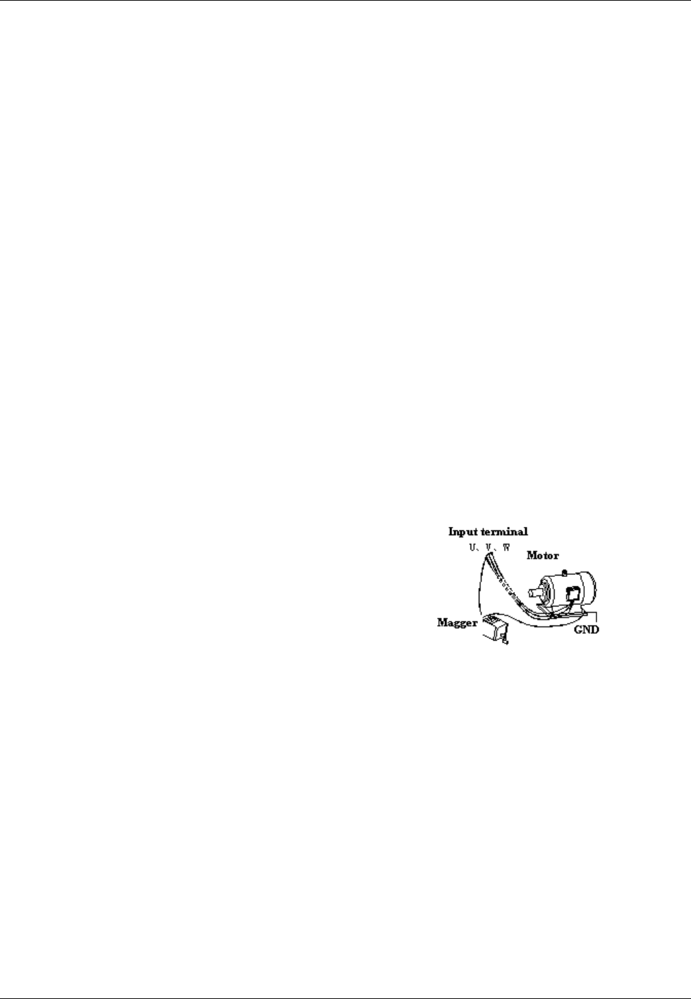
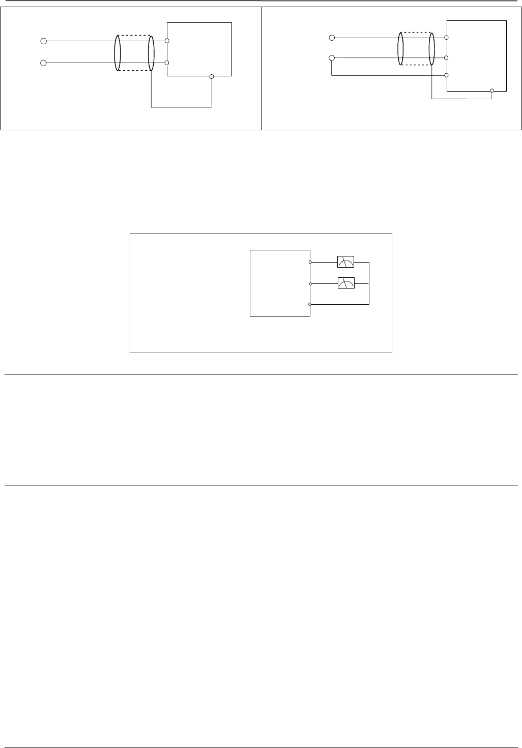
Insulation of Motors
Before using the drive, the insulation of the motors must
be checked, especially, if it is used for the first time or if
it has been stored for a long time. This is to reduce the
risk of the Drive from being damaged by the poor
insulation of the motor. Wiring diagram is shown in Fig.
1-1. Please use 500V insulation tester to measure the
insulating resistance. It should not be less than 5MΩ.
Fig. 1-1 checking the insulation of motor
1.3.2 About Variable Frequency Drive
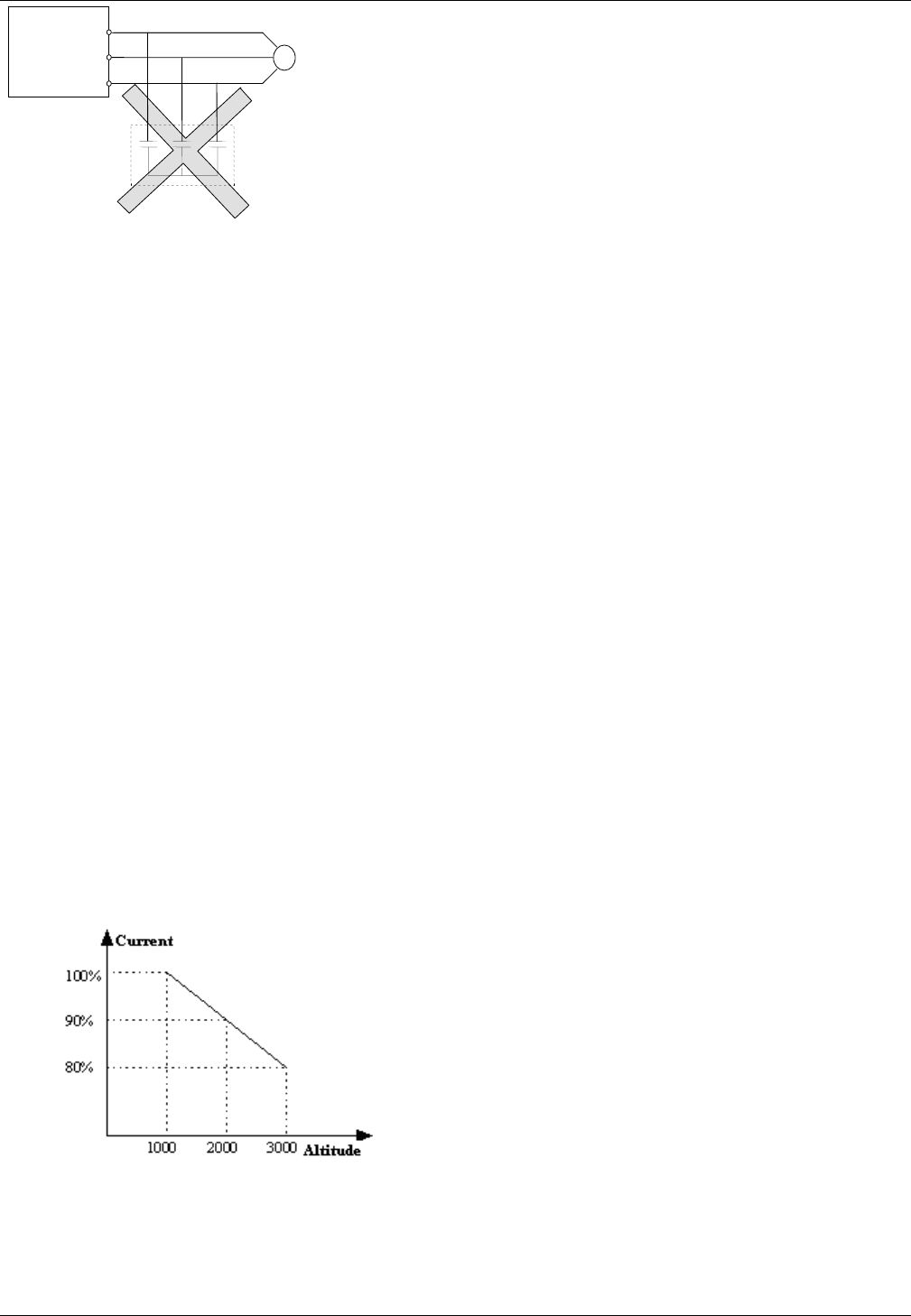
Varistors or Capacitors Used to Improve the Power
Factor
Considering the drive output PWM pulse wave, please
don't connect any varistor or capacitor to the output
terminals of the drive, otherwise tripping or damaging of
components may occur; as shown in fig 1.2
3
3
Fig. 1-2 Capacitors are prohibited to be used.
Circuit breakers connected to the output of VFD
If circuit breaker or contactor needs to be connected
between the drive and the motor, be sure to operate these
circuit breakers or contactor when the drive has no
output, to avoid damaging of the drive.
Using VFD beyond the range of rated voltage
The drive is not suitable to be used out of the
specified range of operation voltage. If needed, please
use suitable voltage regulation device.
Protection from lightning
There is lighting-strike over-current device inside
the Drive which protects it against lighting.
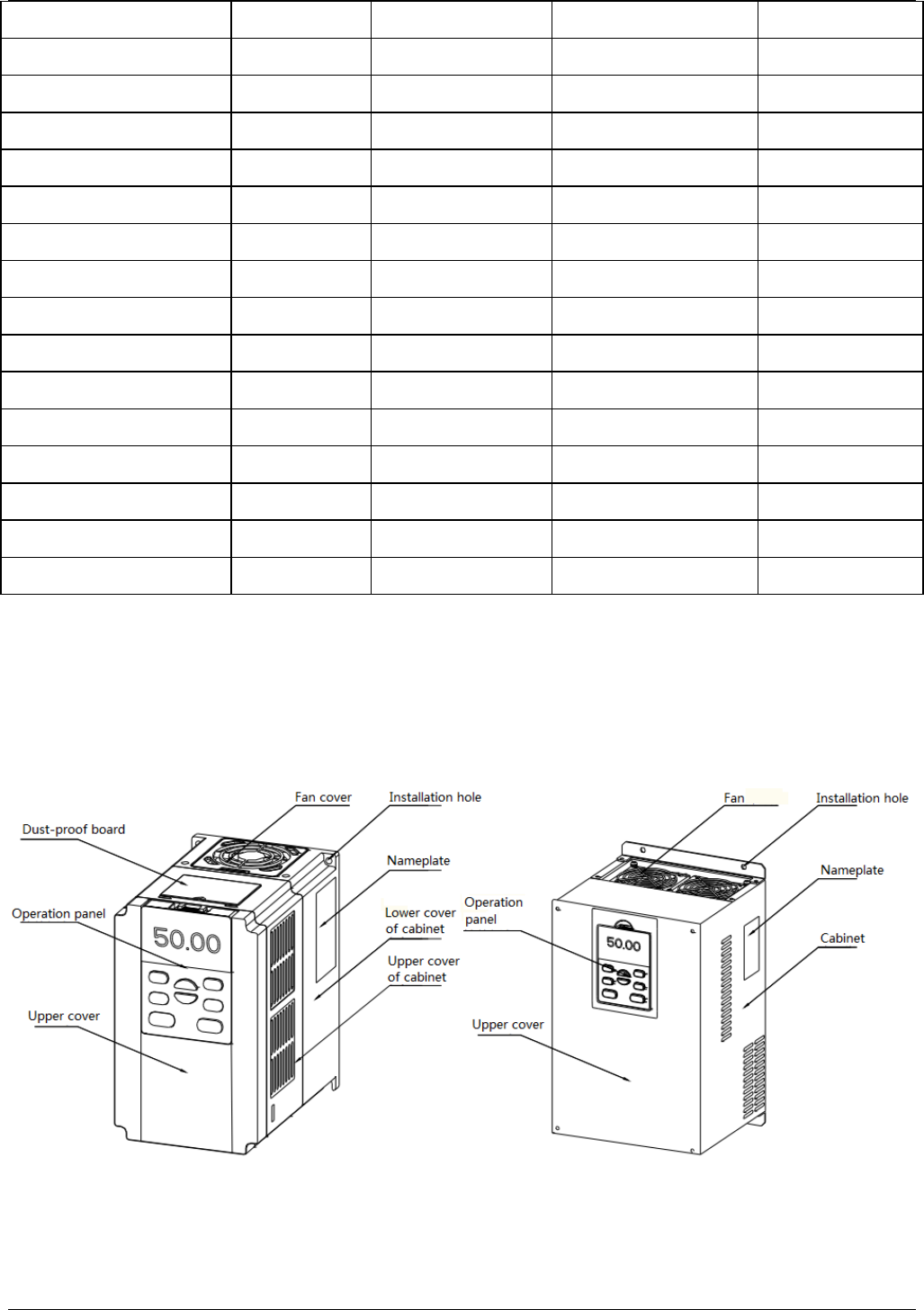
Derating due to altitude
Derating must be considered when the drive is
installed at high altitude, greater than 1000m. This is
because the cooling effect of drive is deteriorated due to
the thin air, as shown in Fig.1-3 that indicates the
relationship between the altitude and rated current of the
driver.
Fig. 1-3 Derating Drive's output current with altitude
1.4 Disposing Unwanted Driver
When disposing the VFD, pay attention to the following
issues:
The electrolytic capacitors in the driver may explode
when they are burnt.
Poisonous gas may be generated when the plastic parts
like front covers are burnt.
Please dispose the drive as industrial waste.
M
U
V
W
FV100

4
4
Chapter 2 Product introduction
In this chapter we introduce the basic product information of specifications, model, and structure and so on.
2.1 General specifications
Table 2-1 General specifications
Item Description
Input
Rated voltage and
frequency 5T:3-phase,480V~540V AC; 50Hz/60Hz;
Allowable voltage
range 5T: 420V~560V AC; Voltage tolerance<3%; Frequency: ±5%
Output
Rated voltage 0~Rated input voltage
Frequency 0Hz~300Hz(Customized 0Hz~3000Hz)
Overload capacity G type : 150% rated current for 1 minute, 180% rated current for 10 seconds;
L type :110% rated current for 1 minute, 150% rated current for 1 second
Control
Charact
eristics
Control mode Vector control without PG, Vector control with PG; V/F control
Modulation mode Space vector PWM modulation
Starting torque
0.5Hz 150%rated torque(Vector control without PG), 0Hz 200% rated torque
(Vector control with PG)
Frequency accuracy Digital setting:Max frequency ×±0.01%;Analog setting:Max. frequency ×±0.2%
Frequency
resolution Digital setting: 0.01Hz;Analog setting: Max frequency×0.05%
Torque boost Manual torque boost :0%~30.0%
V/F pattern 4 patterns: 1 kind of V/F curve mode set by user and 3 kinds of torque-derating
modes (2.0 order, 1.7 order, and 1.2 order)
Acc/Dec curve Linear acceleration/deceleration, Four kinds of acceleration/deceleration time are
optional
Auto current limit Limit current during the operation automatically to prevent frequent over-current trip
Customi
zed
function
Jog Range of jog frequency: 0.20Hz~50.00Hz; Acc/Dec time of Jog operation: 0.1~60.0s,
Interval of Jog operation is also settable.
Multiple speed
operation Implement multiple speed operation by digital inputs
Operatio
n
function
Operation command Keypad setting, terminal setting, communication setting
Frequency
command setting Digital setting, Analog voltage setting, Analog current setting, Pulse setting

5
5
Auxiliary frequency
setting Implement flexible auxiliary frequency trim and frequency synthesis.
Pulse output
terminal 0.1~100kHz pulse output. For example setting frequency, output frequency etc.
Analog output
terminal
2 channels analog output (0/4~20mA or 0/2~10V). For example setting frequency,
output frequency etc.
Operatio
n panel
LED Display Display frequency setting, frequency output, voltage output, current output and so on,
about 20 parameters.
Parameters copy Copy parameters by operation panel.
Keys lock and
function selection
Lock part of keys or all the keys. Define the function of part of keys, in case of
misoperation.
Protection function Open phase protection (optional), overcurrent protection, overvoltage protection,
undervoltage protection, overheat protection, and overload protection and so on.
Environ
ment
Operating site Indoor, installed in the environment free from direct sunlight, dust, corrosive gas,
combustible gas, oil mist, steam and drip.
Altitude Derated above 1000m, the rated output shall be decreased by 10% for every rise of
1000m
Ambient
temperature -10℃~40℃, derated at 40℃~ 50℃
Humidity 5%~95%RH, non-condensing
Vibration Less than 5.9m/s² (0.6g)
Storage temperature -40℃~+70℃
Structur
e
Protection class IP20
Cooling method Air cooling, with fan control.
Installation method Wall-mounted
Efficiency Power under 45kW≥93%;Power above 55kW≥95%
2.2 Introduction of product series
Table 2-1 Series of Kinco VFD
Model of VFD Rated capacity
(kVA)
Rated input current
(A)
Rated output current
(A) Motor power(kW)
FV100‐5T‐0075G/0110L11.0/17.020.5/26.017.0/25.07.5/11
FV100‐5T‐0110G/0150L17.0/21.026.0/35.025.0/32.011/15
FV100‐5T‐0150G/0185L21.0/24.035.0/38.532.0/37.015/18.5
FV100‐5T‐0185G/0220L24.0/30.038.5/46.537.0/45.018.5/22
FV100‐5T‐0220G/0300L30.0/40.046.5/62.045.0/60.022/30
FV100‐5T‐0300G/0370L40.0/50.062.0/76.060.0/75.030/37
6
6
FV100‐5T‐0370G/0450L50.0/60.076.0/92.075.0/90.037/45
FV100‐5T‐0450G/0550L60.0/72.092.0/113.090.0/110.045/55
FV100‐5T‐0550G/0750L72.0/100.0113.0/157.0110.0/152.055/75
FV100‐5T‐0750G/0900L100.0/116.0157.0/180.0152.0/176.075/90
FV100‐5T‐0900G/1100L116.0/138.0180.0/214.0176.0/210.090/110
FV100-4T-0075G/0110L 11.0/17.0 20.5/26.0 17.0/25.0 7.5/11
FV100-4T-0110G/0150L 17.0/21.0 26.0/35.0 25.0/32.0 11/15
FV100-4T-0150G/0185L 21.0/24.0 35.0/38.5 32.0/37.0 15/18.5
FV100-4T-0185G/0220L 24.0/30.0 38.5/46.5 37.0/45.0 18.5/22
FV100-4T-0220G/0300L 30.0/40.0 46.5/62.0 45.0/60.0 22/30
FV100-4T-0300G/0370L 40.0/50.0 62.0/76.0 60.0/75.0 30/37
FV100-4T-0370G/0450L 50.0/60.0 76.0/92.0 75.0/90.0 37/45
FV100-4T-0450G/0550L 60.0/72.0 92.0/113.0 90.0/110.0 45/55
FV100-4T-0550G/0750L 72.0/100.0 113.0/157.0 110.0/152.0 55/75
FV100-4T-0750G/0900L 100.0/116.0 157.0/180.0 152.0/176.0 75/90
FV100-4T-0900G/1100L 116.0/138.0 180.0/214.0 176.0/210.0 90/110
2.3 Structure of VFD
The structure of VFD is as following figure.
FV100-5T-0037G/0055L and below power FV100-5T-0055G/0075L and above power
Fig 2-1 Structure chart of VFD
7
7
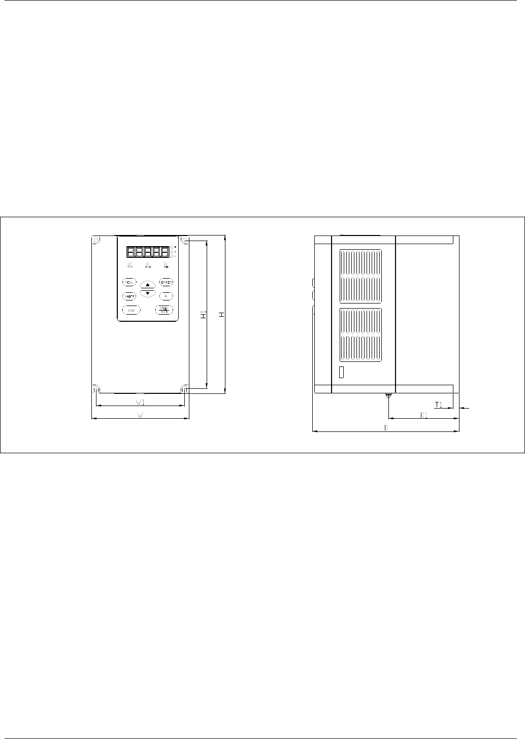
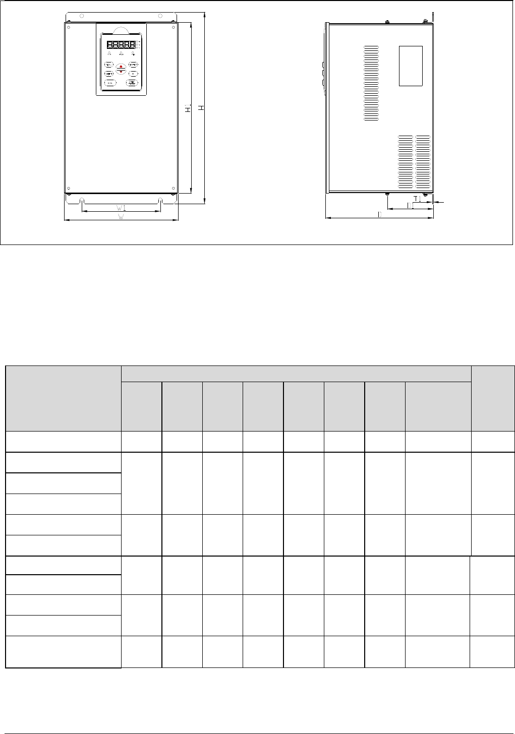
2.4 External dimension and weight
2.4.1 External dimension and weight
External dimension and weight is as following figure.
Fig 2-2 FV100-5T-0037G/0055L and lower power VFD
8
8
Fig 2-3 FV100-5T-0055G/0075L~FV100-5T-0900G/1100L
Table 2-2 Mechanical parameters
VFD model
(G:Constant torque load;
L: Draught fan and
water pump load)
External dimension and (mm)
Weight
(kg)
W H D W1 H1 D1 T1 Installation
hole(d)
FV100-5T-0075G/0110L 165274193110264‐ 266
FV100-5T-0110G/0150L
194324197120312‐ 268
FV100-5T-0150G/0185L
FV100-5T-0185G/0220L
FV100-5T-0220G/0300L
297 451 224 200 433 ‐ 3718
FV100-5T-0300G/0370L
FV100-5T-0370G/0450L
32053522422051288.531031
FV100-5T-0450G/0550L
FV100-5T-0550G/0750L
373649262240628102.5 31042
FV100-5T-0750G/0900L
FV100-5T-0900G/1100L 4407582853407371022.51173
9
9
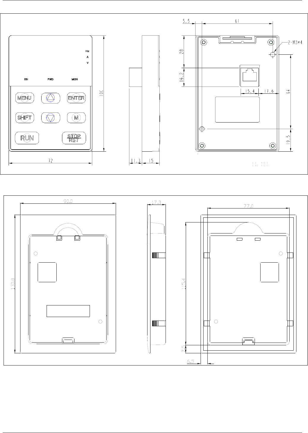
2.4.2 Operation panel and installation box
Fig 2-4 Operation panel dimension
Fig 2-5 Installation box dimension

10
10
2.4.3 Braking Resistor Selection
VFD Model Braking Unit
Braking resistor
Standard
resistance Qty. Min. resistance Standard power
FV100-5T-0075G/0110L
Built-in
50Ω125Ω1600W
FV100-5T-0110G/0150L
FV100-5T-0150G/0185L 40Ω125Ω2000W
FV100-5T-0185G/0220L 32Ω120Ω4800W
FV100-5T-0220G/0300L
Built-in
(optional)
27.2Ω120Ω4800W
FV100-5T-0300G/0370L 20Ω114Ω6000W
FV100-5T-0370G/0450L 16Ω114Ω9600W
FV100-5T-0450G/0550L 15Ω 113.6Ω 9600W
FV100-5T-0550G/0750L
External
20Ω213.6Ω6000W*2
FV100-5T-0750G/0900L 20Ω213.6Ω9600W*2
FV100-5T-0900G/1100L 18Ω 313.6Ω 9600W*3
11
11
Chapter 3 Installation Environment
In this chapter we introduce the installation environment of VFD
Please mount the drive vertically inside a well-ventilated location.
When considering mounting environment, the following issues should be taken into account:
- Ambient temperature should be within the range of-10℃~40℃. If the temperature is higher than 40 ℃, the drive
should be derated and forced ventilation is required;
- Humidity should be lower than 95%,non-condensing
- Install in the location where vibration is less than 5.9m/s² (0.6g);
- Install in the location free of direct sunlight.
- Install in the location free of dust, metal powder.
- Install in the location free of corrosive gas or combustible gas.
If there are any special requirements for installation, please contact us for clarifications.
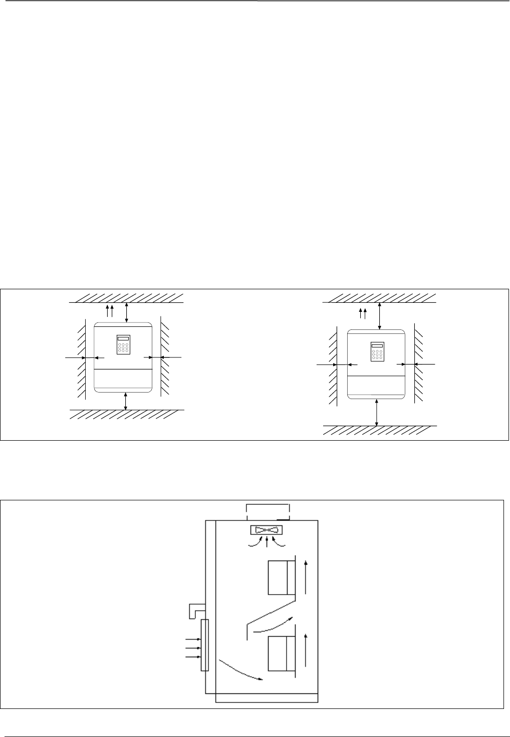
The requirements on mounting space and clearance are shown in Fig. 3-1 and Fig. 3-2.
Fig 3-1 Installation interval (Power below 45kW)Fig 3-2 Installation interval(Power above 55kW)
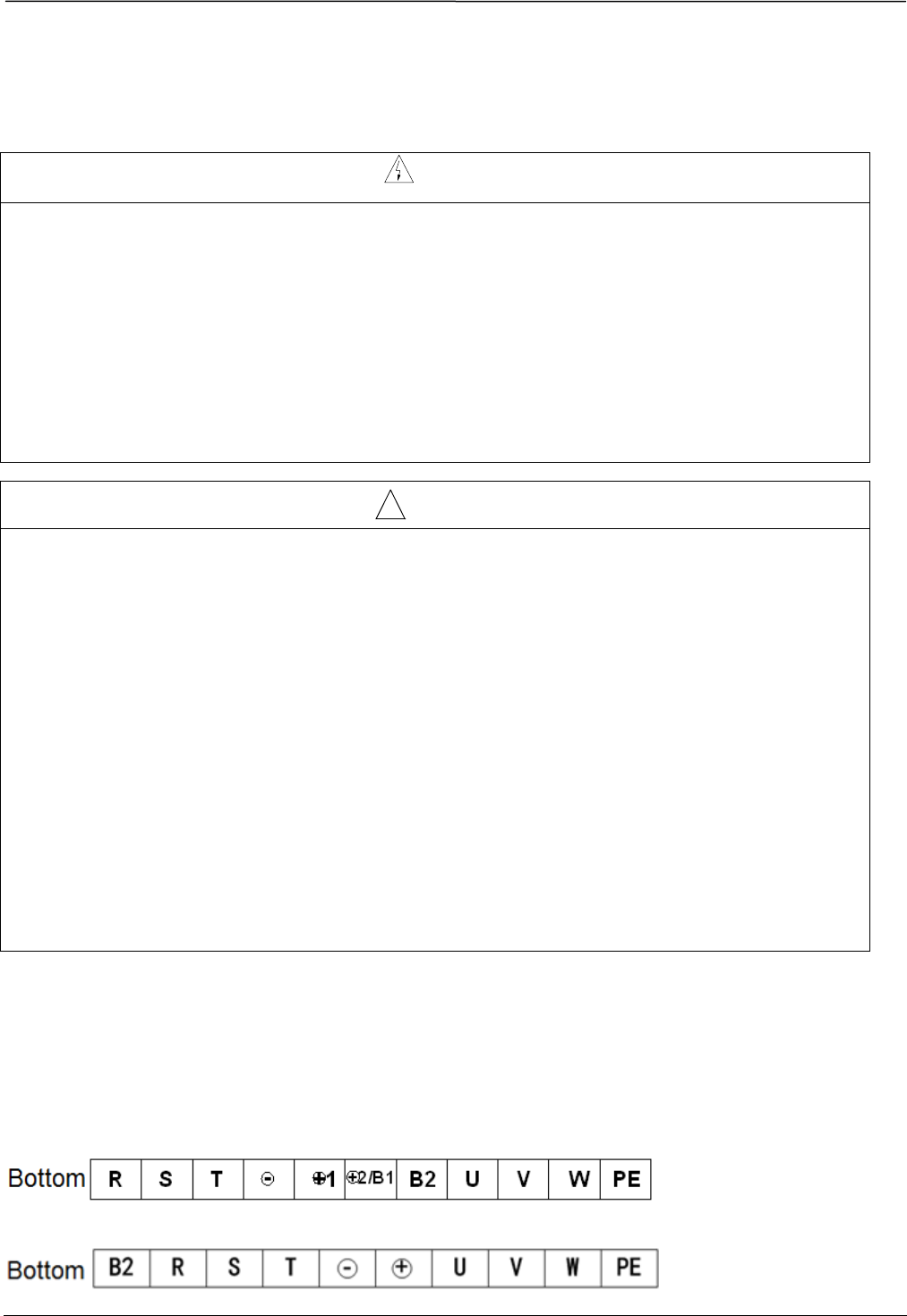
When two VFD are mounted and one is on the top of another, an air flow diverting plate should be fixed in between
them as shown in Fig. 3-3.
Fig 3-3 Installation of several VFD
>3 5c
m
>15 cm
Fan ariflow
>15c
m
>35 c
m
>5c m
>10cm
Fan airfl
ow
>5cm
>10c m
12
12
Chapter 4 Wiring Guide of VFD
In this chapter we introduce the wiring of VFD
Danger
·Wiring can only be done after the drive’s AC power is disconnected, all the LEDs on the operation panel are off
and waiting for at least 10 minutes. Then, you can remove the panel.
·Wiring job can only be done after confirming the charge indicator on the right bottom is off and the voltage
between main circuit power terminals + and - is below DC36V.
·Wire connections can only be done by trained and authorized person
·Check the wiring carefully before connecting emergency stop or safety circuits.
·Check the drive’s voltage level before supplying power to it, otherwise human injuries or equipment damage
may happen.
! Attention
·Check whether the Variable Speed Drive’s rated input voltage is in compliant with the AC supply voltage
before using.
·Dielectric strength test of the drive has been done in factory, so you need not do it again.
·Refer to chapter 2 on connected braking resistor or braking kit.
·It is prohibited to connect the AC supply cables to the drive’s terminals U, V and W.
·Grounding cables should be copper cables with section area bigger than 3.5mm², and the grounding resistance
should be less than 10Ω.
·There is leakage current inside the drive. The total leakage current is greater than 3.5mA, depending on the
usage conditions. To ensure safety, both the drive and the motor should be grounded, and a leakage current
protector (RCD) should be installed. It is recommended to choose B type RCD and set the leakage current at
300mA.
·The drive should be connected to the AC supply via a circuit breaker or fuse to provide convenience to input
over-current protection and maintainance.
4.1 Wiring and Configuration of Main circuit terminal
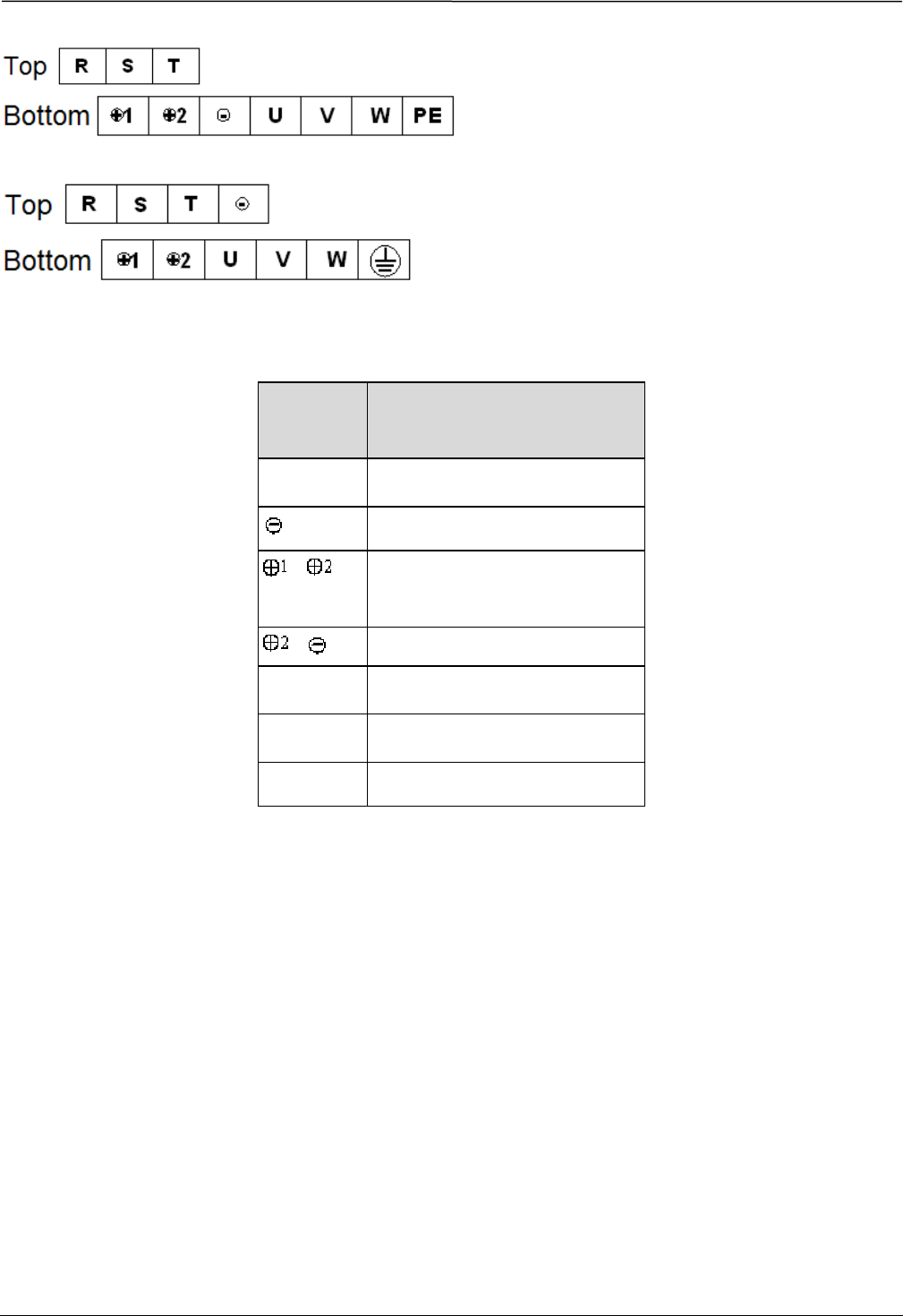
4.1.1 Terminal Type of Main Loop’s Input and Output
Terminal Type
Applicable models:FV100-5T-0075G/0110L~FV100-5T-0185G/0220L
Applicable models:FV100-5T-0220G/0300L~FV100-5T-0450G/0550L
13
13
Applicable models:FV100-4T-0550G/0750L~FV100-4T-0750G/0900L
Applicable models:FV100-4T-0900G/1100L
Table 4-1 Description of main loop terminal
Terminal
name Function description
R、S、T 3-phase 480V AC input terminal
DC negative bus output terminal
、 Reserved terminal for external DC
reactor
、 External braking unit
B1、B2 Braking resistor terminal
U、V、W 3-phase AC output terminal
PE Shield PE terminal
14
14
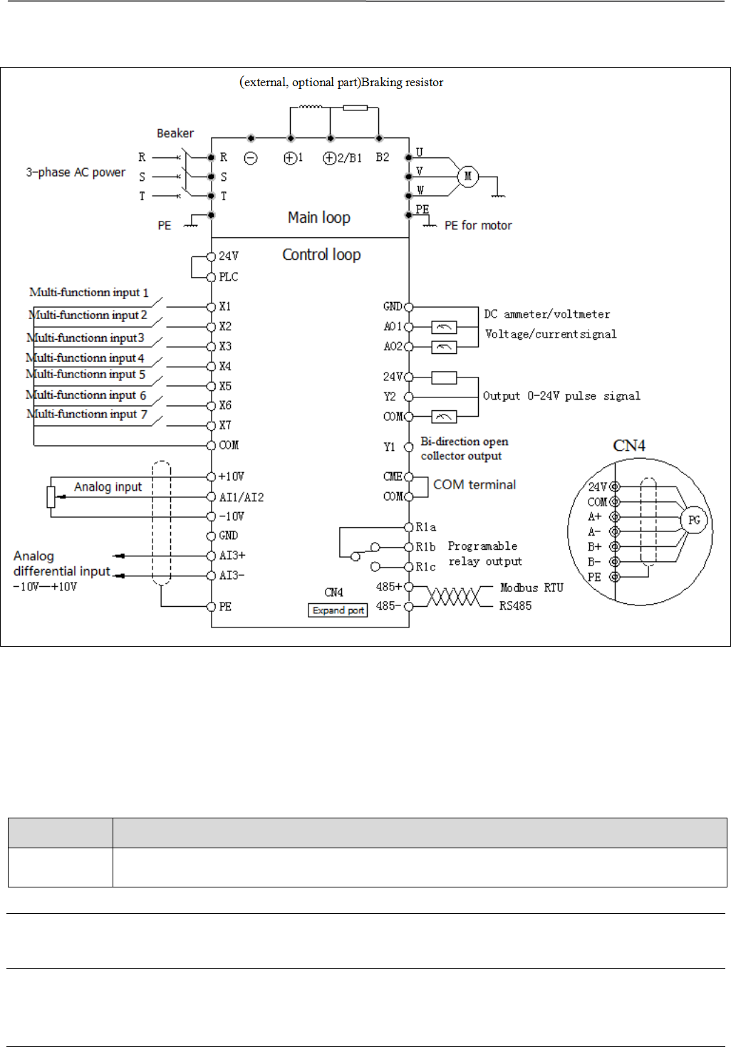
4.1.2 Wiring of VFD for Basic Operation
Applicable model: FV100-5T-0075G /0110L
Fig.4-1 Basic wiring chart
4.2 Wiring and configuration of control circuit
4.2.1 Wiring of control circuit terminal.
Wire the terminals correctly before using the Drive. Refer to the table 4-2 for control circuit terminal function
Table 4-2 Control circuit terminal function
Sequence No. Function
1 Analog input and output terminal, RS232 and RSRS485 communication port
Note
It is recommended to use cables bigger than 1mm2 to connect to the terminals.

15
15
Arrangement of control circuit terminals is as follows
AO1 AO2 AI3+ +10V 24V PLC X4 X5 X6 X7
AI1 AI2 AI3- GND X1 X2 X3 COM
485+
485-
R1a R1b R1c
CME Y1 Y2
Fig.4-2 Arrangement of control terminals
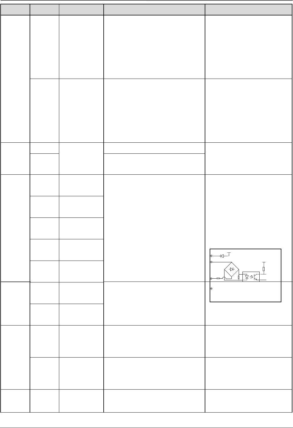
Refer to table 4-3 and 4-4 for description of each terminal
Table 4-3 function list of each list
Category Terminals Name Function description Specification
Shield Shielded PE
PE terminal connected to shielding
layer. 485 communication cable,
Analog signal cable, motor power cable
shield can be connected to this terminal
here
Connected to PE terminal of main
loop inside
Power
supply
+10 +10V Power
supply Provide +10V power supply Maximum current output is 5mA
GND +10V GND of
Power supply
GND for analog signal and 10V power
supply
Isolated from COM and CME
inside
Analog
input
AI1 Signal-ended
input AI1
Can accept analog voltage or current
input, jumper AI1 can select voltage or
current input mode. (Reference ground:
GND)
Input voltage range: -10V~10V
(Input impedance 45KΩ)
Resolution: 1/4000
Input current range : 0mA~20
mA, Resolution: 1/2000(Need
jumper)
AI2 Signal-ended
input AI2
Can accept analog voltage or current
input, jumper AI2 can select voltage or
current input mode. (Reference ground:
GND)
AI3+
Analog voltage
differential input
AI3+ or analog
voltage
single-ended
input
When connected to the analog voltage
differential input, AI3+ is the
same-phase input and AI3- is the
inverted phase input;
when connected to the analog voltage
single-ended input, AI3+ is signal
input,AI3- should connect to GND
(Reference ground: GND)
Input voltage range: -10V~+10V
(Input resistor: 15kΩ)
Resolution: 1/4000
AI3-
Analog voltage
differential input
AI3- or analog
voltage
single-ended
input
16
16
Category Terminals Name Function description Specification
Analog
output
AO1 Analog output 1
Providing analog voltage or current
output, they are selected by the jumper
AO1. The default setting is output
voltage, refer to the function code
A6.28 for detail.(Reference ground:
GND)
Voltage output range: 0V~10V
Current output range: 0/4~20mA
AO2 Analog output 2
Providing analog voltage or current
output, they are selected by the jumper
AO2. The default setting is output
voltage, refer to the function code
A6.29 for detail.(Reference ground:
GND)
Voltage output range: 0V~10V
Current output range: 0/4~20mA
Communi
cation
RS485+ RS485
communication
port
485+ Standard RS-485 communication
port, please use twisted-pair cable
or shielded cable.
RS485- 485-
Multi-fun
ction
input
terminal
X1 Multi-function
input terminal 1
Can be defined as multi-function digital
input terminal.(Refer to the A6 group,
form A6.00 to A6.06)
Optocoupler isolation input
Input resistor: R=3.3kΩ
Maximum frequency input of
X1~X6: 200Hz
Maximum input frequency of X7:
100kHz
Input voltage range:2~30v
X2 Multi-function
input terminal 2
X3 Multi-function
input terminal 3
X4 Multi-function
input terminal 4
X5 Multi-function
input terminal 5
X6 Multi-function
input terminal 6
X7 Multi-function
input terminal 7
Multi-fun
ction
output
terminal
Y1
Bi-direction
open-collector
output
Can be defined as multi-function digital
output terminal , refer to the A6.14 for
detail (Com port: CME)
Optocoupler isolation output
Maximum working voltage: 30v
Maximum output current: 50mA
Y2 Open collector
pulse terminal
Can be defined as multi-function pulse
signal output terminal , refer to the
A6.25 for detail(Com port: CME)
Maximum output frequency:
100kHz(Depend on the A6.26)
Power
supply 24V
+24V power
supply
Providing +24V power for others Maximum output current: 200mA
+24V
X1、。。。X7
PLC +3.3V
COM
24V
R
17
17
Category Terminals Name Function description Specification
Common
port
PLC
Common port of
multi-function
input
Common port of Multi-function input
(Short cut with 24V in default)
Common port of X1~X7, PLC is
isolated from 24V internally
COM
Common port of
24V power
supply
Three common ports in all, cooperate
with other terminals
COM is isolated from
CME and GND inside the drive
CME common port of
Y1output
Common port of multi-function output
terminal Y1
Relay
output
terminal 1
R1a
Relay output
Can be defined as multi-function relay
output terminal(Refer to the A6.16 for
detail)
R1a-R1b:Normally closed,
R1a-R1c:normally open
Contact capacity :
AC250V/2A(COSΦ=1)
AC250V/1A(COSΦ=0.4)
DC30V/1A
Input voltage for overvoltage
class of relay output terminal
is overvoltage class II
R1b
R1c
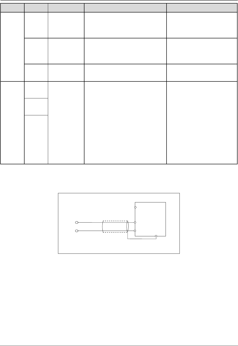
Wiring of analog input
1) AI1, AI2 can be connected to analog voltage or current single-ended input. Use a jumper can select AI1 as Voltage
model and AI2 as current mode. The wiring is as follows:
Fig 4-3 AI1,AI2 terminal wiring
2) AI3+,AI3- can be connected to the analog differential or single-ended input , the wiring is as follows:
Shield cable connec
t
to PE
AI1,AI2
G
N
D
+10
- 10 ~+ 1 0V
Or
0~20 mA
PE
FV100
18
18
Fig 4-4 AI+,AI- differential voltage input wiring Fig 4-5 AI+,AI- single-ended voltage input wiring
Wiring of analog output terminal
If the analog output terminals AO1 and AO2 are connected to analog meters, then various kinds of physical values can
be measured. The jumper can select current output (0/4~20mA) or voltage output (0/2~10V). The wiring is as follows:
Fig.4-6 Wiring of analog output
Notes:
1. When using analog input, a filter capacitor common mode inductor can be installed between signal input and GND
2. The analog input voltage is better under 15V.
3. Analog input and output signals are easily disturbed by noise, so shielded cables must be used to transmit these
signals and the cable length should be as short as possible.
4. The analog output terminal can stand the voltage under 15V
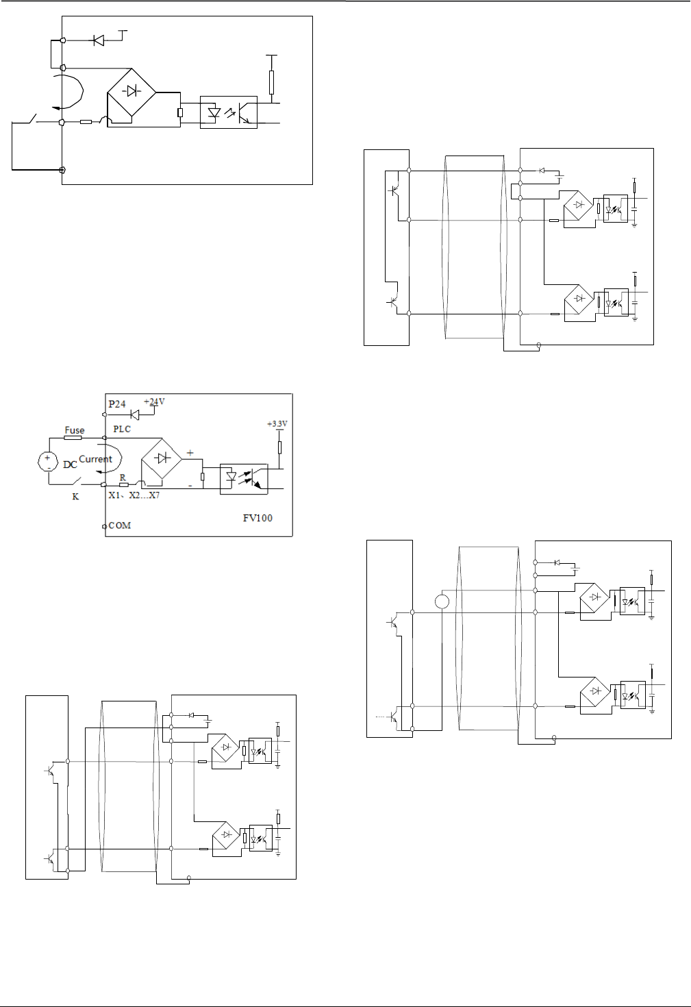
Wiring of multiple function input terminal and
operation terminal
FV100 multi-function input terminal uses a full-bridge
rectifying circuit as shown in Fig.4-7. PLC is the
common terminal of terminals X1~X7, The current
flows through terminal PLC can be pulling current and
the feeding current. Wiring of X1~X7 is flexible and the
typical wiring are as follows:
1. Dry contacts method
1) Use the internal 24V power supply of VFD, the
wiring is as in fig.4-7.
AO1
AO2
GND
FV100
PE
-10V~+10V
Shield cable connected to PE
G
N
D
AI3+/AI3-
AI3+/AI3-
FV100
AI +
AI- PE
FV100
- 0 V
~ + 10 V
Analog differential
voltage input
Shield cable
connected to PE
Analog meters
19
19
Fig.4-7 Wiring method of using the internal 24V power
supply
2) Use external power supply, (The power supply must
satisfy the UL CLASS 2 standard and a 4A fuse must be
added between the power supply and terminal), the
wiring is as Fig.4-8 (Make sure the PLC and 24V
terminal is disconnected)
Fig.4-8 Wiring of external power supply
2. Source/drain connection method
1) Use internal +24V power supply of VFD and the
external controller uses NPN transistors whose common
emitter are connected, as shown in the fig.4-9
Fig.4-9 Use internal power supply
for Source connection
2) Use internal +24V power supply and the external
controller uses PNP transistors whose common emitter
are connected, as shown in the fig 4-10(Make sure the
PLC and 24V terminal is disconnected). The wiring is as
shown in fig.4-10
Fig 4-10 Use internal power supply
for drain connection
3) Use external power supply for source connection
(Make sure the PLC and 24V terminal is disconnected).
As shown in the fig.4-11
Fig 4-11 Use external power supply
for source connection
4) Use external power supply for drain connection
(Make sure the PLC and 24V terminal is disconnected).
As shown in the fig 4-12
¡ñ
¡ñ
¡ñ
¡ñ
¡ñ
¡ñ
¡ñ
¡ñ ¡ñ
24V +
-
Shielded cable's end near the drive
should be connected to the PE
FV100
PE
1
PLC
X1
24V
COM 24V DC
D2
+
-
+3.3V
10 X7
+3.3V
¡ñ
¡ñ
¡ñ
¡ñ
¡ñ
¡ñ
¡ñ
¡ñ ¡ñ
COM
PE
1
PLC
X1
24V
COM
D2
+
-
+3.3V
10 X7
+3.3V
24V DC
Shielded cable's end near the drive
should be connected to the PE
COM
¡
FV100
PE
¡
1¡
PL
X1
¡
¡
24V
CO
¡
¡
24V
D2
+
-
+3.3
10 ¡
X7
¡
+3.3V
External controlle
r
+24V
X1
、
X2...X7
PLC
FV100
+3.3V
COM
24V
R
+
-
K
Current
Shielded cable's end near the drive
should be connected to the PE
20
20
Fig 4-12 Use external power supply
for drain connection
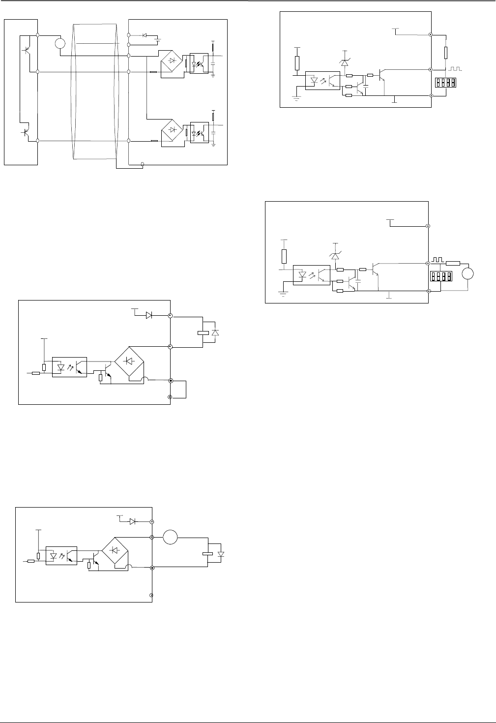
Multi-function output terminal wiring
1. Multi-function output terminal Y1 can use the internal
24 power supply, the wiring is as shown in Fig.4-13
Fig 4-13 Wiring method 1 of multi-function
output terminal Y1
2. Multi-function output terminal Y1can use the external
24 power supply too, the wiring is as shown in Fig.4-14.
Fig 4-14 Wiring method 2 of multi-function
output terminal Y1
3. Y2 can also be used as pulse frequency output, If Y2
uses the internal 24V power supply. The wiring is shown
in Fig.4-15.
Fig 4-15 Wiring method 1 of output terminal Y2
4. When Y2 is used as a digital pulse frequency output, it
can also use the external power supply. The wiring is
shown in Fig.4-16
Fig.4-16 Wiring method 2 of output terminal Y2
Wiring of relay output terminals R1a, R1b and R1c
If the drive drives an inductive load (such as
electromagnetic relays and contactor), then a surge
suppressing circuit should be added, such as RC
snubbing circuit (Notice that the leakage current must be
smaller than the holding current of the controlled relay
or contactor) and varistor or a free-wheeling diode (Used
in the DC electric-magnetic circuit and pay attention to
the polarity when installing). Snubbing components
should be as close to the coils of relay or contactor as
possible.
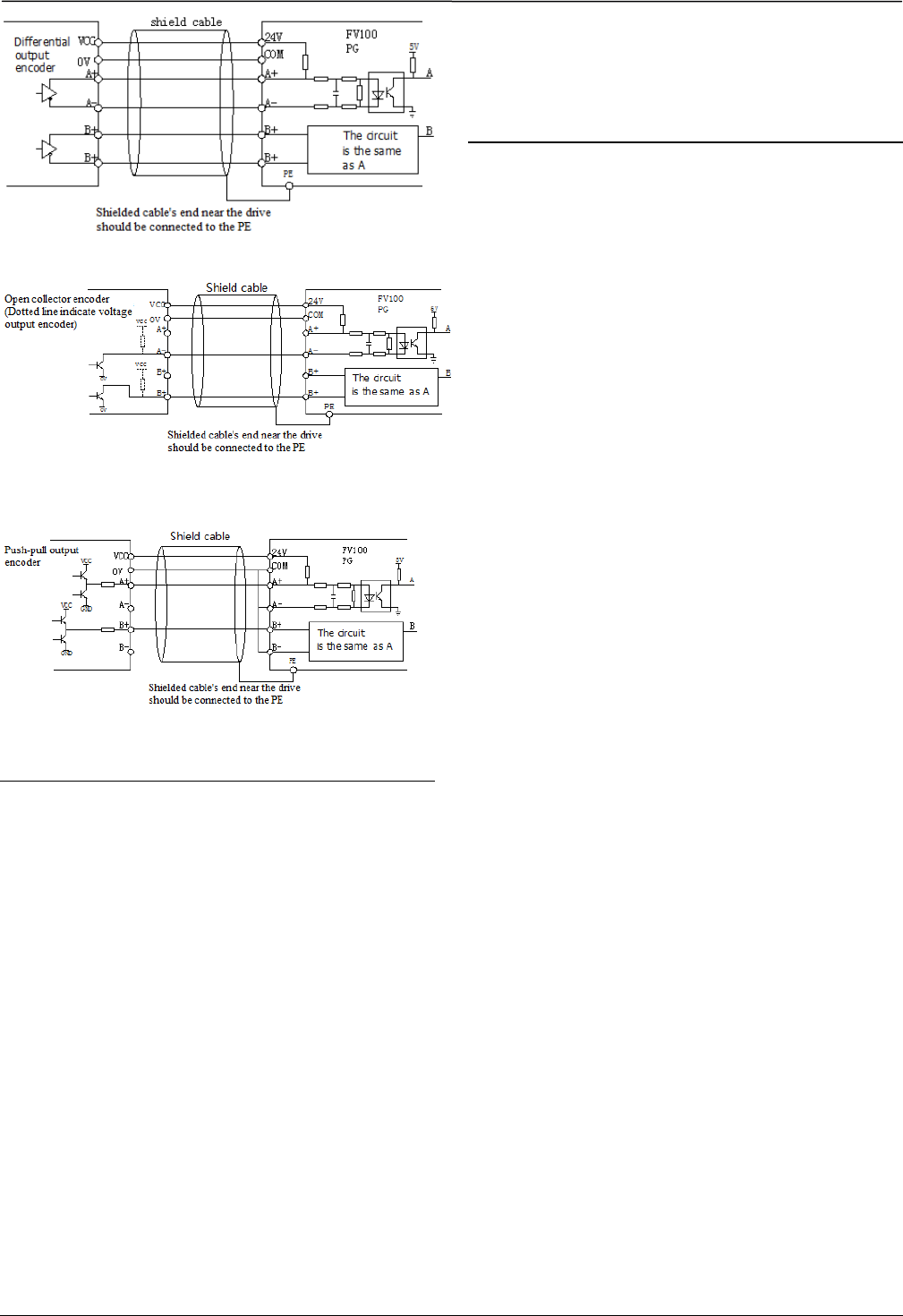
5. Attentions for encoder (PG) wiring
Connection method of PG signal must be corresponding
with PG model. Differential output, open collector
output and push-pull output encoder wirings are shown
in Fig.4-17, 4-18 and 4-19.
DC
FV100 COM
Y1
24V
+5V
+24V
+ -
Rela
y
DC
+24V 24V
4.7
k
Y2
COM
+5V +24V
+
-
FV100
+24V
FV100
24V
4.7k
Y2
COM
+5V +24V
FV100 COM
24V
+5V
+24V
CME
Y1
Relay
¡ñ
¡ñ
¡ñ
¡ñ
¡ñ
¡ñ
¡ñ
¡ñ ¡ñ
+
-
24V
FV100
PE
1
PLC
X1
24V
COM 24V DC
D2
+
-
+3.3V
10 X7
External controlle
r
+3.3V
Shielded cable's end near the drive
should be connected to the PE
Digital
frequency meter
CME
21
21
Fig 4-17 Wiring of differential output encoder
Fig.4-18 Wiring of open collector output encoder
Fig.4-19 Wiring of push-pull output encoder
Note
1. Don’t short circuit terminals 24V and COM,
otherwise the control board may be damaged.
2. Please use multi-core shielded cable or multi-stranded
cable (above 1mm²) to connect the control terminals.3.
When using a shielded cable, the shielded layer’s end
that is nearer to the drive should be connected to PE.
4. The control cables should be as far away(at least
20cm) from the main circuits and high voltage cables as
possible (including power supply cables, motor cables,
relay cables and contactor cables and so on). The cables
should be vertical to each other to reduce the disturbance
to minimum.
5. The resistors R in Fig. 4-13 and Fig.4-14 should be
removed for 24V input relays, and the resistance of R
should be selected according the parameters of relay for
non-24V relay.
6. Digital output terminal can not stand the voltage
higher than 30V
22
22
Chapter 5 Operation Instructions of Kinco VFD
In this chapter we introduce the necessary knowledge of Kinco VFD and related operations.
5.1 Using Operation Panel
5.1.1 Operation panel appearance and keys’ function description
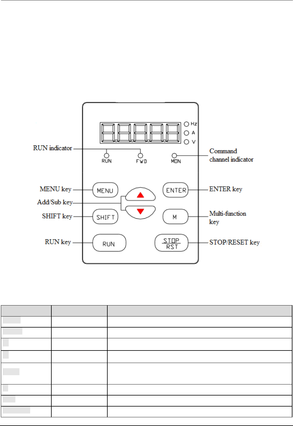
Operation panel is used to setup the drive and display parameters, it is LED display. As shown in Fig.5-1
Fig.5-1 Illustration of operation panel
There are 8 keys on the operation panel and functions of each key are shown in Table 5-1.
Table 5-1 Function list of operation panel
Key Name Function
MENU Program/exit key Enter or exit programming status
ENTER Function/data key Enter next level menu or confirm data
∧ Increase key Increase data or parameter
∨ Decrease key Decrease data or parameter
SHIFT Shift key In editing status, press this key to select the Bit to be modified. In other
status, this key is used to switch the parameters to display.
M Multi-function key Use the b4.01 to configure the function of this key
RUN Run key In panel control mode, press this key to run the drive.
STOP/RST Stop/reset key Press this key to stop or reset the drive.

23
23
5.1.2 Function Descriptions of LED and Indicators
The operation panel consists of a 5-digits eight segments LED display, 3 LED indicators for unit and 3 LED indicators
for status which is as shown in Fig.5-1. The LED display can display the status parameters, function codes and error
codes of the drive. The 3 unit indicators are corresponding to three units, the descriptions of three status indicator are
shown in table 5-2
Table 5-2
Indicator Status Current status of drive
Operating status
indicator(RUN)
Off Stop
On Run
Operating
direction
indicator(FWD)
Off Forwards
On Reverse
Operating mode
indicator(MON)
On Controlled by operation
panel
Off Controlled by terminals
Flashing Communicating
5.1.3 Display status of operation panel
FV100 operation panel can display the parameters in stopping, operating, editing and function code..
1. Parameters displayed in stopping status
When the drive is in stop status, the operation panel displays the stop status parameter. Pressing the SHIFT key can
display different stop status parameters in cycle (Defined by function code b4.05)
2. Parameters displayed in operation status
When the drive receives operating command, it starts running and its panel will display the operation status parameters,
the RUN indicator turns on. The status of FWD indicator depends on the operation direction. The unit indicator display
the unit of the parameter, by pressing the SHIFT key can display different operation parameters in cycle (Defined by
function code b4.05)
3. Parameters displayed in error status
When the drive detects a fault signal, the panel will display the flashing fault code..
Press the SHIFT key to display the stop status parameters and error code in cycle. By pressing the STOP/RST, control
terminal or communication command to reset the error. If the error exists still, then the panel keeps displaying the error
code.
4. Parameter edit status
When the drive is in stop, operation or error state, press MENU/ESC can enter edit status (If password needed, please
refer to description of A0.00),. Edit state displays in 2-level menu, they are: function code group or function code
number→function code parameter value. You can press ENTER to enter parameter displayed status. In function
parameter displayed status, press ENTER to save the settings, and press MENU to exit the menu.
24
24
5.1.4 Panel Operation
Various operations can be completed on the operation panel; the following are 5 common examples. Refer to function
code list in chapter 9 for detail function code description.
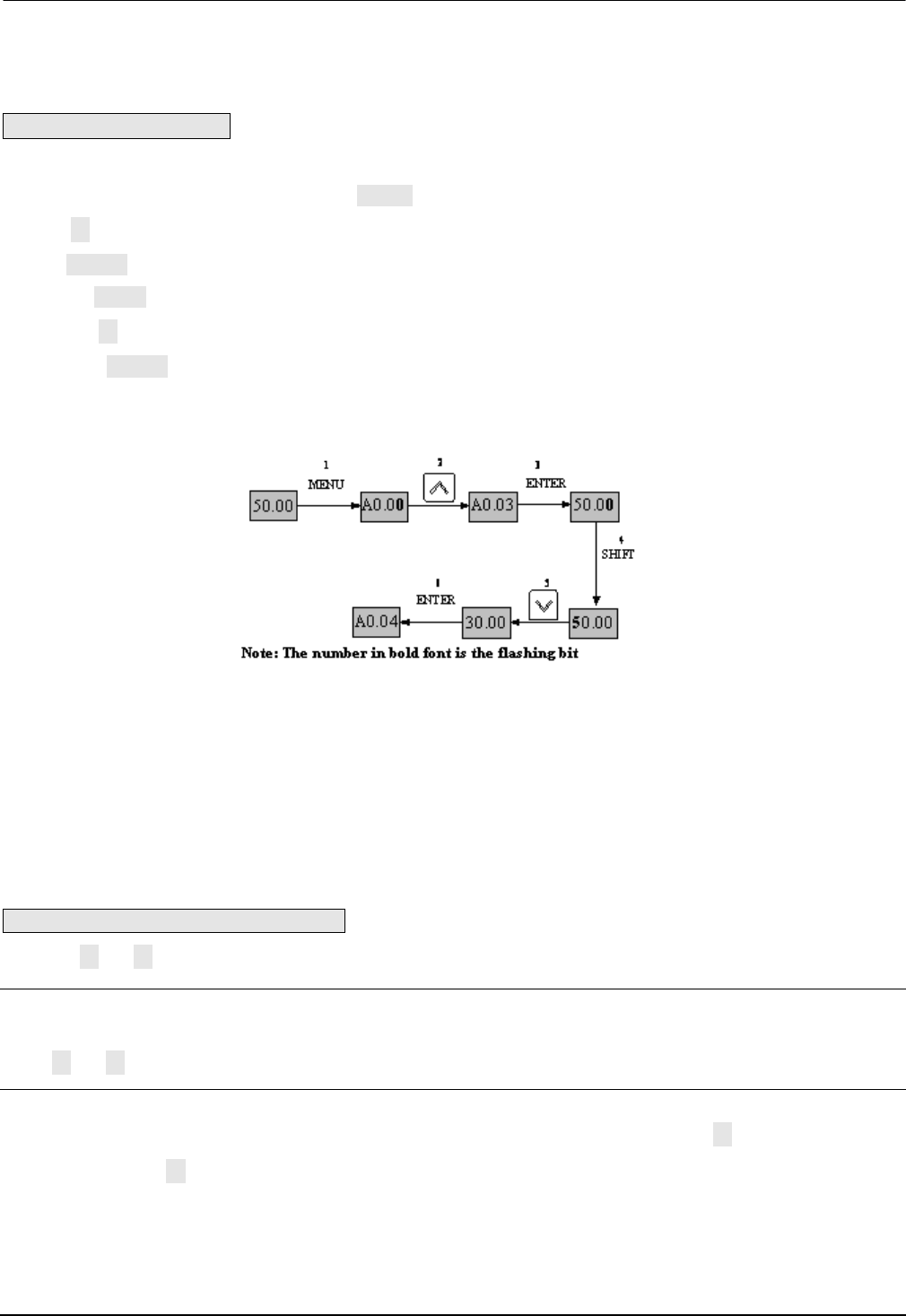
Example 1:Set parameters
Example: Change the value in A0.03 from 50.00Hz to 30Hz
1. In the stop parameter displaying state, press MENU to enter the first level A0.00;
2. Press ∧ to change A0.00 to A0.03;
3. Press ENTER to enter the second level menu
4. Press the SHIFT to change the marker to the highest bit
5. Press the ∨ to change the 50.00 to 30.00
6. Press the ENTER to confirm above change and back to the fist level menu. Then the parameter is changed
successfully.
The above operations are shown in following picture.
Fig 5-2 Example of setting parameter
In function parameter displaying status, if there is no bit flashing. It means that this function code can not be changed,
the possible reason are:
1. This function code is unchangeable parameter. Like actual detected parameter, operation log parameter and so on
2. This parameter can not be changed when running; you need stop the VFD to edit the parameter
3. The parameters are protected. When the b4.02 is 1, function code can not be changed. It is to protect the VFD from
wrong operation. If you want to edit this parameter, you need set function code b4.02 to 0.
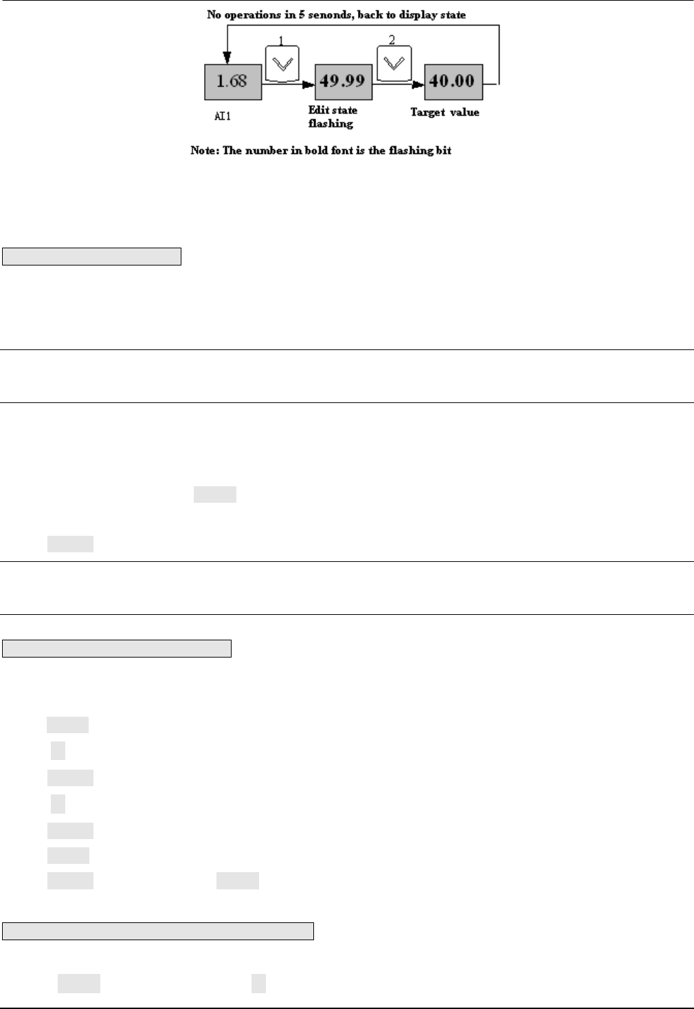
Example 2: Regulate the setting frequency
Press the ∧ or ∨ to change the setting frequency directly when power on VFD
Note:
When the Operating Speed, Setting Speed, Operating Line Speed, and Setting Line Speed is displayed on the panel.
Press ∧ or ∨ is to modify the value of Setting Speed or Setting Line Speed.
Example: changing the setting frequency from 50.00Hz to 40.00Hz.
After the VFD power on (in this example the LED is in voltage display status AI1), Press ∨ to modify the setting
frequency (Holding ∨ can speed up the modification) from 50.00Hz to 40.00Hz. So the setting frequency is
modified.
The above steps are as the following figure:
25
25
Fig 5-3 Modify the setting frequency
After modification, if there are no operations in 5 seconds, The LED will back to display the voltage, it means to
display the status before modification.
Example 3: Set the password
To protect parameters, the VFD provides password protection function. The user needs to input the right password to
edit the parameters if the VFD has been set password. For some manufacturer parameters, it also need to input correct
manufacturer password.
Note:
Do not try to change the manufacturer parameters. if they are not set properly, the VFD may not work or be damaged.
Function code A0.00 is to set user password. Refer to 6.1 A0 group for more information
Suppose the user’s password to be set as 8614, then the VFD is locked, and you can not do any operation to VFD.
Then you can follow the following steps to unlock the VFD.
1 when the VFD is locked, press MENU. The LED will display the password verification status: 0000;
2 Change 0000 to 8614;
3 Press ENTER to confirm. Then the LED will display A0.01. So the VFD is unlocked
Note:
After unlock the password, if there is no operation in 5 minutes, VFD will be locked again.
Example 4: Lock the operation panel
The b4.00 is used to lock the operation panel. Refer to 6.1 A0 group for more information
Example: Lock all the keys of the operation panel Under stop parameter displaying status.
1 press MENU to enter A.00
2 Press ∧ to choose the function code b4.00
3 Press ENTER to enter the second level menu
4 Press ∧ to change the hundreds place from 0 to 1
5 Press ENTER to confirm
6 Press MENU to back to the stop parameter displaying status;
7 Press ENTER and hold, then press MENU, so the key board is locked
Example 5: Unlock the keys of the operation panel
When the operation panel is locked, follow the follow operations to unlock it:
Press the MENU and hold , then press the ∨ once, so the key boar is unlocked

26
26
Note:
Whatever the setting is in b4.00, after the VFD power on, the operation board is in unlock status.
5.2 Operation mode of VFD
In the follow-up sections, you may encounter the terms describing the control, running and status of drive many times.
Please read this section carefully. It will help you to understand and use the functions discussed in the follow chapters
correctly.
5.2.1 Control mode of VFD
It defines the physical channels by which drive receives operating commands like START, STOP, JOG and others,
there are two channels:
1 Operation panel control: The drive is controlled by RUN, STOP and M keys on the operation panel;
2 Terminal control: The drive is controlled by terminals Xi、Xj and COM (2-wire mode), or by terminal Xki (3-wire
mode);
The control modes can be selected by function code A0.04, multi-function input terminal (Function No. 15~17 are
selected by A6.00~A6.06 ).
3 Modbus communication: by using host computer to control the VFD to start or stop.
Note:
Before you change the control mode, make sure that the mode suitable for the application. Wrong selection of control
mode may cause damage to equipment or human injury!
5.2.2 Operating Status
There are 3 operating status: stop, motor parameters auto-tuning, and operating.
1. Stop status: After the drive is switched on and initialized, if no operating command is accepted or the stop command
is executed, then the drive in stop status.
2. Operating status: The drive enters operating status after it receives the operating command.
3. Motor parameters auto-tuning status: If there is an operating command after b0.11 is set to 1 or 2, the drive then
enters motor parameters auto-tuning status, and then enters stopping status after auto-tuning process finishes.
5.2.3 Control mode and operation mode of Kinco VFD
Control mode
FV100 VFD has three control methods, it is set by A0.01:
1. Vector control without PG: it is vector control without speed sensor, need not to install the PG, at the same time it
has very high control performance, it can control the speed and torque of motor accurately. It has the characteristics
like low frequency with high torque and steady speed with high accuracy. It is often used in the applications that the
V/F control mode can not satisfy, but require high robustness.
2. Vector control with PG: The PG is needed, the PG is installed on the shaft of controlled motor to ensure the control
performance. It is used in the applications that require high torque response, and much higher accuracy of torque and
speed control.
27
27
3. V/F control: It is used in the applications that do not require very high performance, such as one VFD controls
multiple motors.
Operation mode
Speed control: Control the speed of motor accurately, related function codes in A5 group should be set.
Torque control: Control the torque of motor accurately, related function codes in A5 group should be set.
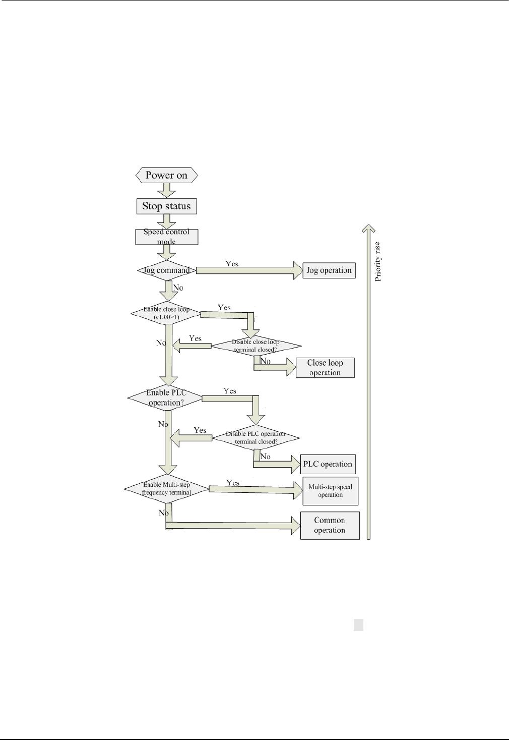
5.2.4 The channels to set the VFD frequency
FV100 supports 5 kinds of operating modes in speed control mode which can be sequenced according to the priority:
Jog>Close loop process operation>PLC operation>Multiple speed operation>simple operation. It is shown as follows:
Fig 5-4 Operating mode in speed control mode
The three operating modes provide three basic frequency source.Two of them can use the auxiliary frequency to
stacking and adjusting (except Jog mode), the descriptions of each mode are as follows:
1) JOG operation:
When the drive is in STOP state, and receives the JOG command (for example the M key on the panel is pressed), then
the drive jogs at the JOG frequency (refer to function code A2.04 and A2.05)
2) Close-loop process operation:
If the close-loop operating function is enabled (C1.00=1), the drive will select the close-loop operation mode, that is, it
will perform closed-loop regulation according to the given and feedback value (refer to function code C1 group). This
mode can be deactivated by the multi-function terminals, and switch to the lower priority mode.
28
28
3) PLC operation
This function is customized, description is omitted.
4) Multi-step (MS) speed operation:
Select Multiple frequency 1~15(C0.00~C0.14)to start Multiple speed operation by the ON/OFF combinations of the
multi-function terminals (No.27, 28, 29 and 30 function). If all the terminals are “OFF”,it is in simple operation.
Note:
About the frequency setting channel under speed mode, please refer to the chapter 6 for detail information
5.3 Power on the Drive for the first time
5.3.1 Checking before power on
Please wire the drive correctly according to chapter 4
5.3.2 Operations when start up the first time
After checking the wiring and AC supply, switch on the circuit breaker of the drive to supply AC power to it. The
drive’s panel will display “8.8.8.8.” at first, and then the contactor closes. If the LED displays the setting frequency,that
is to say the initialization of the drive is completed.
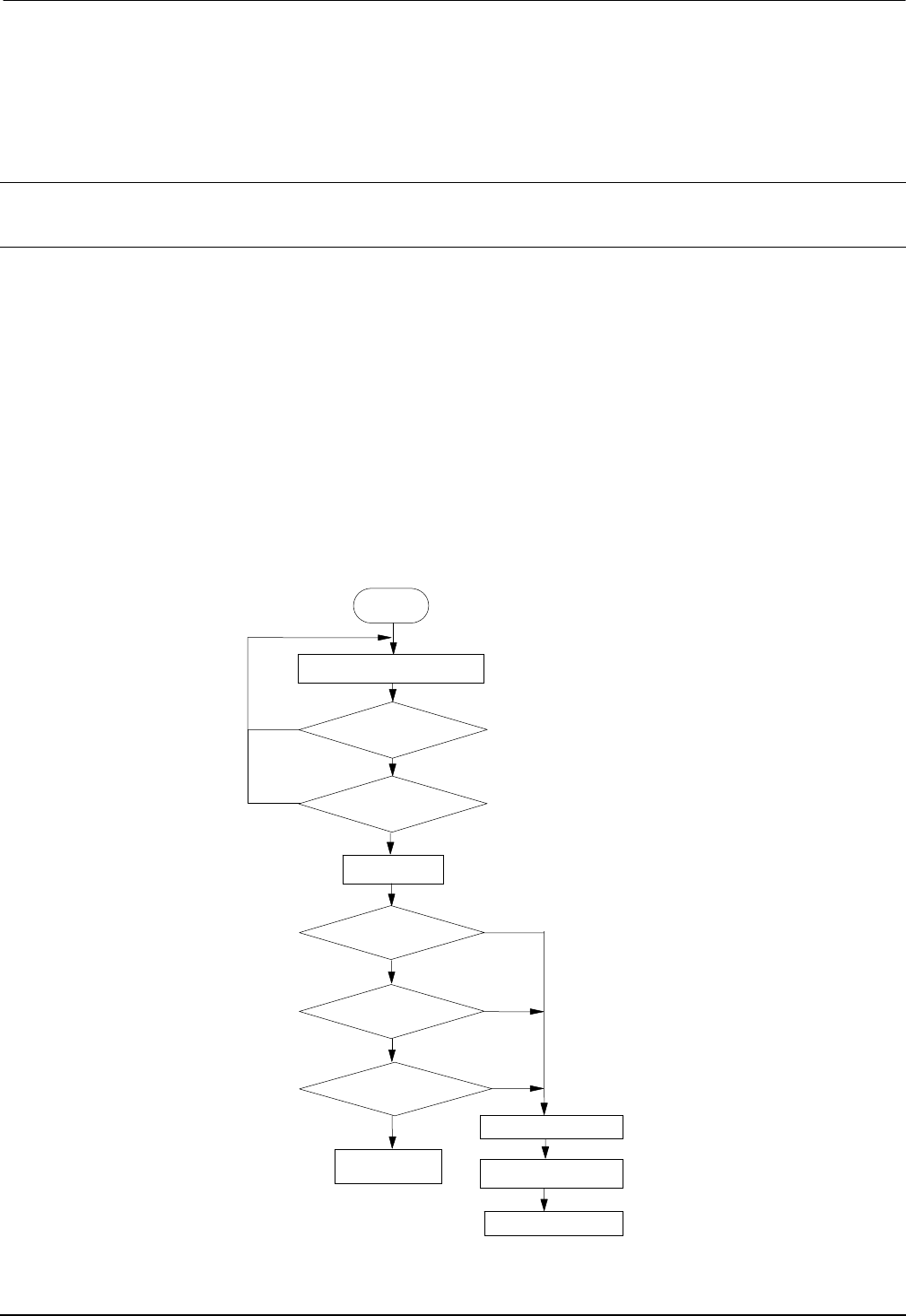
Procedures of first-time start-up are as follows:
Fig.5-5 Procedures of first-time start-up
N
Y
N
Y
N
Y
N
Y
N
Y
Properly wiring
Power on
Display
8.8.8.8?
.
Contactor closed?
Successful
Check the reason
Start
Check wiring
Check input
voltage
Display frequency?
Failed
Cut off the power

29
29
Chapter 6 Parameter Introductions
Note:
6.1 Group A0
A0.00 User password 00000~65535
【00000】
This function is used to prevent the irrelevant personnel
from inquiring and changing the parameter as to protect
the safety of the VFD parameters.
0000: No password protection.
Set password:
Input four digits as user password, and press ENTER
key for confirmation. After 5 minutes without any other
operation,the password will be effective automatically.
Change password:
Press MENU key to enter into the password verification
status. Input correct password, and it enters parameter
editing status. Select A0.00 (parameter A0.00 displayed
as 00000).Input new password and press ENTER key for
confirmation. After 5 minutes without any other
operation,the password will be effective automatically.
Note:
Please safekeeping the user password.
A0.01 Control mode 0~2【2】
0: Vector control without PG (Open loop vector control)
It is a vector control mode without speed sensor
feedback.It is applicable to most applications.
1: Vector control with PG (Closed loop vector control)
It is a vector control with speed sensor feedback.It is
applicable to applications with high accuracy
requirement of speed control precision,torque control
and simple servo control.
2:V/F control
It is used to make the voltage and frequency in a
constant ratio. It is applicable to most application,
especially for the application of one drive to drive
multiple motors.
A0.02 Main reference
frequency selector 0~4【0】
0: Digital setting.
The VFD will regard the value in A0.03 as the initial
reference frequency when power on.
It can be adjusted via ▲ and ▼ key on the panel(panel
control),or adjusted via setting the function of terminal
to be UP/DOWN function(set any two of Xi to be 13 and
14, terminal control )
X1~X7
choose any
two of them
13 Frequency ramp up (UP)
14 Frequency ramp down (DN)
1: Set via AI1 terminal.
The reference frequency is set by analog input via
terminal AI1 and the voltage range is -10V~10V. The
relationship between voltage and reference frequency
can be set in Group A3.
2: Set via AI2 terminal.
The reference frequency is set by analog input via
terminal AI2 and the voltage range is -10V~10V. The
relationship between voltage and reference frequency
can be set in Group A3.
3: Set via AI3 terminal.
The reference frequency is set by analog input via
terminal AI3 and the voltage range is -10V~10V. The
relationship between voltage and reference frequency
can be set in Group A3.
4: Set via X7/DI terminal (PULSE).
Set the reference frequency by the X7 terminal’s
frequency of pulse input .The relationship between pulse
frequency and reference frequency can be set in Group
A3.
5: Reserved.
XX. XX YYYYYY
N
1
~
N
2
【
D
】
Parameter
No. Parameter
Name Range
Default
value

30
30
A0.03 Set the operating
frequency in digital mode
Range: Lower limit of
frequency ~upper limit
of frequency
【50.00Hz】
When the main reference frequency is set in digital
mode(A0.02=0), this setting of A0.03 is the drive’s
initial frequency value.
A0.04 Methods of inputting
operating commands 0~2【0】
FV100 has two control modes.
0: Panel control:Input operating commands via panel
Start and stop the drive by pressing RUN, STOP and M
on the panel.
1: Terminal control: Input operating commands via
terminals.
Use external terminals Xi(Set function code
A6.00~A6.06 to 1 and 2),M Forward, M Reverse to start
and stop the drive.
2:Modbus communication.
A0.05 Set running direction 0~1【0】
This function is active in panel control mode , and
inactive in terminal control mode.
0: Forward
1: Reverse
A0.06 Acc time 1
0.0~6000.0s
【6.0s】
A0.07 Dec time 1
0.0~6000.0s
【6.0s】
Default value of Acc/Dec time 1:
2kW or below:6.0S
30kW~45kW:20.0S
45kW or above:30.0S
Acc time is the time taken for the motor to accelerate
from 0Hz to the maximum frequency (as set in A0.08).
Dec time is the time taken for the motor to decelerate
from maximum frequency (A0.08) to 0Hz.
FV100 series VFD has defined 4 kinds of Acc/Dec
time.(Here only Acc/Dec time 1 is defined, and Acc/Dec
time 2~4 will be defined in A4.01~A4.06),and the
Acc/Dec time 1~4 can be selected via the combination
of multiple function input terminals,please refer to
A6.00~A6.07.
A0.08 Max. output
Frequency
Max{50.00,A0.11 upper limit of
frequency}~300.00Hz【50.00】
A0.09 Max. output
Voltage 0~480V【VFD’s rating values】
A0.10 Upper limit
of frequency A0.11~A0.08【50.00】
A0.11 Lower limit
of frequency 0.00~A0.10【00.00】
A0.12 Basic
operating frequency 0.00~300【50.00】
Max output frequency is the highest permissible output
frequency of the drive, as shown in Fig. 6-1 as Fmax;
Max output voltage is the highest permissible output
voltage of the drive, as shown in Fig. 6-1 as Vmax
Upper limit of frequency is the highest permissible
operating frequency of the user setting, as shown in Fig.
6-1 as FH.
Lower limit of frequency is the lowest permissible
operating frequency of the user setting,as shown in
Fig.6-1 as FL.
Basic operating frequency is the Min. frequency when
the drive outputs the max voltage in V/F mode, as shown
in Fig. 6-1 as Fb
Fig.6-1 Characteristic parameters
FLFHFbFma x
Vmax
Output
Voltage
Output frequency

31
31
Note:
1.Please set Fmax, FH and FL carefully according to
motor parameters and operating states.
2.FH and FL is invalid for JOG mode and auto tuning
mode.
3.Besides the upper limit of frequency and lower limit
of frequency,the drive is limited by the setting value of
frequency of starting,starting frequency of DC braking
and hopping frequency.
4.The Max. output frequency,upper limit frequency and
lower limit frequency is as shown in Fig.6-1.
5.The upper/lower limit of frequency are used to limit
the actual output frequency.If the preset frequency is
higher than upper limit of frequency,then it will run in
upper limit of frequency.If the preset frequency is lower
than the lower limit of frequency,then it will run in lower
limit of frequency.If the preset frequency is lower than
starting frequency,then it will run in 0Hz.
A0.13 Torque boost of motor 1 0.0~30.0%【0.0%】
In order to compensate the torque drop at low frequency,
the drive can boost the voltage so as to boost the torque.
This function code is corresponding to maximum output
voltage.
If A0.13 is set to 0, auto torque boost is enabled and if
A0.13 is set non-zero, manual torque boost is enabled,
as shown in Fig. 6-2.
Fig.6-2 Torque boost(shadow area is the boostedvalue)
Note:
1. Wrong parameter setting can cause overheat or
over-current protection of the motor.
2. Refer to b1.07 for definition of fz.
6.2 Group A1
A1.00 Starting mode 0、1、2【0】
0.Start from the starting frequency
Start at the preset starting frequency (A1.01) within the
holding time of starting frequency (A1.02).
1.Brake first and then start
Brake first(refer to A1.03 and A1.04), and then start in
mode 0.
2.Speed tracking
Notes:
Starting mode 1 is suitable for starting the motor that is
running forward or reverse with small inertia load when
the drive stops. For the motor with big inertial load, it is
not recommended to use starting mode 1.
A1.01 Starting frequency
0.00~60.00Hz
【0.00Hz】
A1.02 Holding time of starting
Frequency 0.00~10.00s【0.00s】
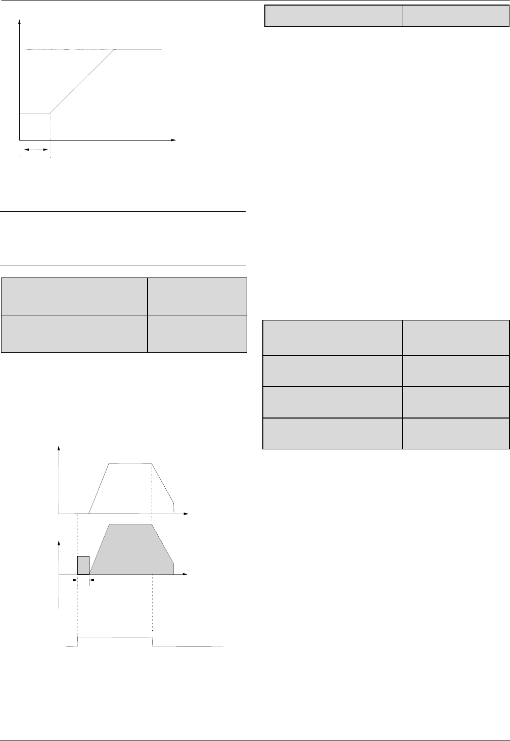
Starting frequency is the initial frequency when the drive
starts, as shown in Fig. 6-3 as FS; Holding time of
starting frequency is the time during which the drive
operates at the starting frequency, as shown in Fig. 6-3
as t1
Vb:Manual torque boost Vmax: Max. output voltage
Fz:Cut-off frequency for torque boost Fb:Basic operating frequency
Output
voltage
Fb
Vb
Vmax
Output frequency
F
z
32
32
Fig.6-3 Starting frequency and starting time
Note:
Starting frequency is not restricted by the lower limit of
frequency.
A1.03 DC injection braking
current at start 0.0~100.0%【0.0%】
A1.04 DC injection braking
time at start 0.00~30.00s【0.00s】
A1.03 and A1.04 are only active when A1.00 is set to 1
(starting mode 1 is selected), as shown in Fig. 6-4.
DC injection braking current at start is a percentage
value of drive’s rated current. There is no DC injection
braking when the braking time is 0.0s.
Fig.6-4 Starting mode 1
A1.05 Stopping mode 0、1、2【0】
0: Dec-to-stop
After receiving the stopping command, the drive reduces
its output frequency according to the Dec time, and stops
when the frequency decreases to 0.
1: Coast-to-stop
After receiving the stopping command, the drive stops
outputting power immediately and the motor stops under
the effects of mechanical inertia.
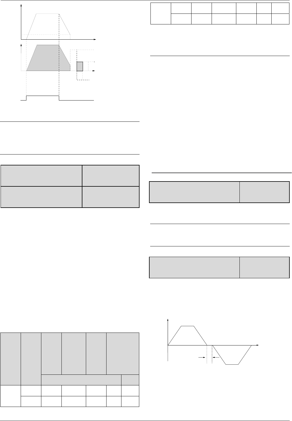
2: Dec-to-stop+DC injection braking
After receiving the stop command, the drive reduces its
output frequency according to the Dec time and starts
DC injection braking when its output frequency reaches
the initial frequency of braking process.
Refer to the introductions of A1.06~A1.09 for the
functions of DC injection braking.
A1.06 DC injection braking
initial frequency at stop
0.00~60.00Hz
【0.00Hz】
A1.07 Injection braking
waiting time at stop 0.00~10.00s【0.00s】
A1.08 DC injection braking
current at stop 0.0~100.0%【0.0%】
A1.09 DC injection braking
time at stop 0.00~30.00s【0.00s】
DC injection braking waiting time at stop: The duration
from the time when operating frequency reaches the DC
injection braking initial frequency(A1.06) to the time
when the DC injection braking is applied.
The drive has no output during the waiting time. By
setting waiting time, the current overshoot in the initial
stage of braking can be reduced when the drive drives a
high power motor.
DC injection braking current at stop is a percentage of
drive’s rated current. There is no DC injection braking
when the braking time is 0.0s.
Output
Frequency
DC Braking
energy
DC injection
Braking time
Running
command
Time
Time
Output
Voltage
(effective
Value)
Time( t)
Fs
maxF
Frequency(Hz)
1
t
33
33
Fig.6-5 Dec-to-stop + DC injection braking
Note:
DC injection braking current at stop(A1.08) is a
percentage value of drive’s rated current.
A1.10 Restart after power
failure 0、1【0】
A1.11 Delay time for restart
after power failure 0.0~10.0s【0.0s】
A1.10 and A1.11 decide whether the drive starts
automatically and the delay time for restart when the
drive is switched off and then switched on in different
control modes.
If A1.10 is set to 0, the drive will not run automatically
after restarted.
If A1.10 is set to 1, when the drive is powered on after
power failure, it will wait certain time defined by A1.11
and then start automatically depending on the current
control mode, the drive’s status before power failure and
the command state when power on. See Table 6-1.
Table 6-1 Restarting conditions
Settin
g of
A1.10
Status
before
power
off
Panel Serial
port
3-wire
modes
1 and
2
2-wire
modes 1
and 2
Without control command With
0 Stop 0 0 0 0 0
Run 0 0 0 0 0
1 Stop 0 0 0 0 1
Run 1 1 1 0 1
Table 6-1 shows the drive’s action under different
conditions. “0” means the drive enter ready status and
“1” means the drive start operation automatically.
Note:
1. A1.10 is only enable in 2-wire mode.
2. If there is a stopping command, the drive will stop
first.
3. When the function of restart after power failure is
enabled, the drive will start in the way of speed tracking
mode after power on if it is not switched off totally (that
is, the motor still runs and drive’s LED displays
“P.OFF”). It will start in the starting mode defined in
A1.00 after power on if it is switched off totally (LED
turns off).
A1.12 Anti-reverse running
function 0、1【0】
0: Disabled
1: Enabled
Note:
This function is effective in all control modes.
A1.13 Delay time of run reverse/
forward 0~3600s【0.0s】
The delay time is the transition time at zero frequency
when the drive switching its running direction as shown
in Fig. 6-6 as t1.
Fig.6-6 Delay time from reverse running to forward
running or from forward running to reverse running
Output
Freqency
Initial Frequency
of braking
Braking
energy
Braking time
Operating
command
Waiting time
Time
t1
Output
frequency
Output
Voltage
(RMS value)

34
34
A1.14 Switch mode of run
reverse/forward 0、1【0】
0:Switch when pass 0Hz
1:Switch when pass starting frequency
A1.15 Detecting frequency of
stop 0.00~150.00Hz
A1.16 Action voltage of
braking unit
4T: 650~750【720】
2S: 320~380【380】
A1.17 Dynamic braking 0、1【0】
0:Dynamic braking is disabled
1:Dynamic braking is enabled
Note:
This parameter must be set correctly according to the
actual conditions, otherwise the control performance
may be affected.
A1.18 Ratio of working time
of braking unit to drive’s total
working time
0.0~100.0%【80.0%】
This function is effective for the drive with built-in
braking resistor.
Note:
Resistance and power of the braking resistor must be
taken into consideration when setting this parameters.
A1.19 Restart mode selection
for power failure 0, 1, 2【0】
0: Current search mode
It is only valid in V/F control. If it is not V/F control, it will
run mode 1.
1: Vector tracing mode
It starts in vector control mode.
2: Define by A1.00
It will start according to starting mode set in A1.00.
6.3 Group A2
A2.00 Auxiliary reference
frequency selector 0~5【0】
0:No auxiliary reference frequency
Preset frequency only determined by main reference
frequency,auxiliary reference frequency is 0Hz by
default.
1:Set by AI1 terminal
The auxiliary frequency is set by AI1 terminal.
2:Set by AI2 terminal
The auxiliary frequency is set by AI2 terminal.
3:Set by AI3 terminal
The auxiliary frequency is set by AI3 terminal.
4:Set by DI (PULSE)terminal
The auxiliary frequency determined by the frequency of
input pulse and can be set only by X7 terminal.
5:Set by output frequency of process PID.
A2.01 Main and auxiliary
reference frequency
calculation
0~3【0】
0:”+”
Preset frequency=Main+auxiliary.
Set preset frequency as 0Hz when the polarity of preset
frequency is opposite to main frequency.
1:”-”
Preset frequency=Main-auxiliary.
Set preset frequency as 0Hz when the polarity of preset
frequency is opposite to main frequency.
2: MAX
Set the max. absolute value between Main and auxiliary
reference frequency as preset frequency.
Set Main reference frequency as preset frequency when
the polarity of auxiliary frequency is opposite to main
frequency.
3: MIN
Set the min. absolute value between Main and auxiliary
reference frequency as preset frequency.
Set preset frequency as 0Hz when the polarity of
auxiliary frequency is opposite to main frequency.
A2.02 UP/DN rate 0.01~99.99Hz/s【1.00】
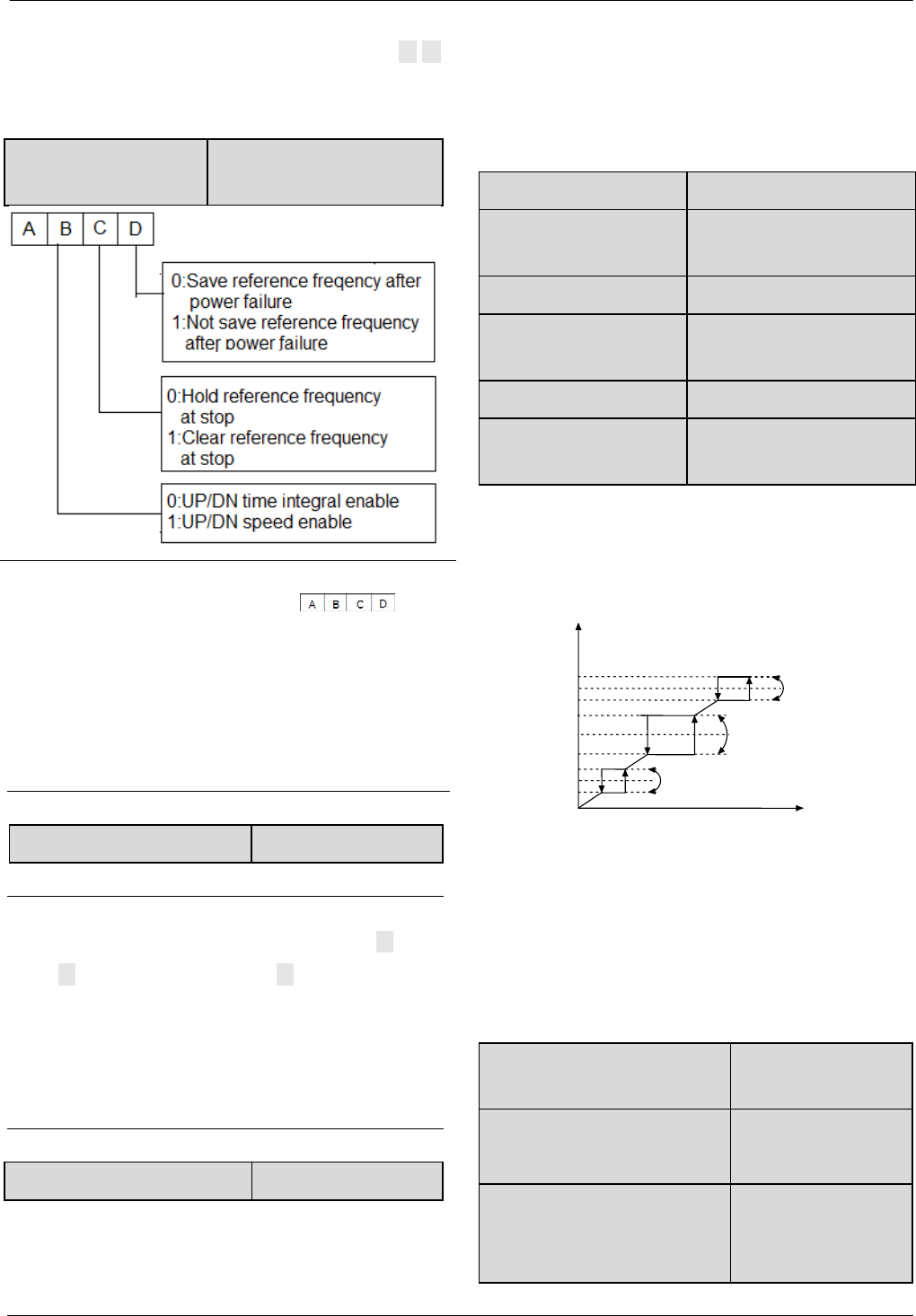
35
35
A2.02 is used to define the change rate of reference
frequency that is changed by terminal UP/DN or ▲/▼
key.
A2.03 UP/DN regulating
control 000~111H【000】
Note:
In this manual,there are many .Their
meanings are as following:
A means the thousand’s place of LED display.
B means the hundred’s place of LED display.
C means the ten’s place of LED display.
D means the unit’s place of LED display.
A2.04 Jog operatin frequency 0.01~50.00【5.00Hz】
A2.04 is used to set the jog operating frequency.
Note:
1. Jog operation can be controlled by panel(M key).
Press M key to run and release M to stop with stop
method (A1.05).
2. Jog operation can also be controlled by terminals. Set
jog forward and jog reserve function for DI to make jog
operation.
A2.05 Interval of Jog operation 0.0~100.0s【0.0】
Interval of Jog operation (A2.05) is the interval from the
time when the last Jog operation command is ended to
the time when the next Jog operation command is
executed.
The jog command sent during the interval will not be
executed. If this command exists, until the end of the
interval, will it be executed.
A2.06 Skip frequency 1 0.00~300.0Hz【0.00Hz】
A2.07 Range of skip
frequency 1 0.00~30.00Hz【0.00Hz】
A2.08 Skip frequency 2 0.00~300.0Hz【0.00Hz】
A2.09 Range of skip
frequency 2 0.00~30.00Hz【0.00Hz】
A2.10 Skip frequency 3 0.00~300.0Hz【0.00Hz】
A2.11 Range of skip
frequency 3 0.00~30.00Hz【0.00Hz】
A2.06~A2.11 define the output frequency that will
cause resonant with the load, which should be avoided.
Therefore, the drive will skip the above frequency as
shown in Fig. 6-7. Up to 3 skip frequencies can be set.
Fig.6-7 Skip frequency and skip range
After setting the parameter of skip frequency, the
outputfrequency of VFD will be adjusted automatically
to avoid resonant frequency.
6.4 Group A3
A3.00 Reference frequency
curve selection 0000~3333H【0000】
A3.01 Max reference of curve1
A3.03~110.0%
【100.0%】
A3.02 Actual value
corresponding to the Max
reference of curve 1
0.0%~100.0%
【100.0%】
Skip
Frequency 1
Skip
Frequency 2
Skip
frequency 3
A
djusted preset
frequency
Skip range 1
Skip range 2
Skip range 3
Preset
frequenc
y
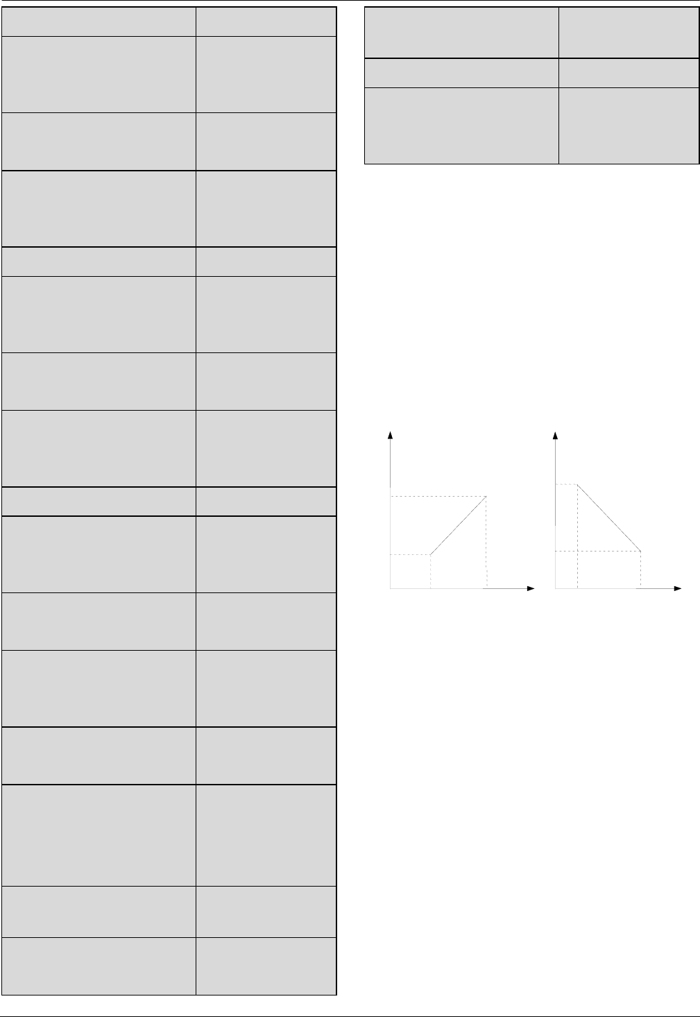
36
36
A3.03 Min reference of curve 1 0.0%~A3.01【0.0%】
A3.04 Actual value
corresponding to the Min
reference of curve 1
0.0%~100.0%
【0.0%】
A3.05 Max reference of curve
2
A3.07~110.0%
【100.0%】
A3.06 Actual value
corresponding to the Max
reference of curve 2
0.0%~100.0%
【100.0%】
A3.07 Min reference of curve 2 0.0%~A3. 05【0.0%】
A3.08 Actual value
corresponding to the Min
reference of curve 2
0.0%~100.0%
【0.0%】
A3.09 Max reference of curve3
A3.11~110.0%
【100.0%】
A3.10 Actual value
corresponding to the Max
reference of curve 3
0.0%~100.0%
【100.0%】
A3.11 Min reference of curve 3 0.0%~A3. 09【0.0%】
A3.12 Actual value
corresponding to the Min
reference of curve 3
0.0%~100.0%
【0.0%】
A3.13 Max reference of curve4
A3.15~110.0%
【100.0%】
A3.14 Actual value
corresponding to the Max
reference of curve 4
0.0%~100.0%
【100.0%】
A3.15 Reference of inflection
point 2 of curve 4
A3.17~A3.13
【100.0%】
A3.16 Actual value
corresponding to the Min
reference of inflection point 2
of curve 4
0.0%~100.0%
【100.0%】
A3.17 Reference of inflection
point 1 of curve 4 A3.19~A3.15【0.0%】
A3.18 Actual value
corresponding to the Min
0.0%~100.0%
【0.0%】
reference of inflection point 1
of curve 4
A3.19 Min reference of curve 4 0.0%~A3. 17【0.0%】
A3.20 Actual value
corresponding to the Min
reference of curve 4
0.0%~100.0%
【0.0%】
Reference frequency signal is filtered and amplified, and
then its relationship with the preset frequency is
determined by Curve 1,2,3 or 4. Curve 1 is defined by
A3.01 ~A3.04.Curve 2 is defined by A3.05 ~
A3.08.Curve 3 is defined by A3.09~A3.12.Curve 4 is
defined by A3.13~A3.20. Take preset frequency as
example,positive and negative characteristics are shown
in Fig.6-8.In Fig.6-8,the inflection points are set the
same as the corresponding relationship of Min. or Max
reference.
Fig.6-8 Freq. corresponding to Min. frequency
Analog input value (A) is a percentage without unit, and
100% corresponds to 0V or 20mA. Pulse frequency (P)
is also a percentage without unit, and 100% corresponds
to the Max pulse frequency defined by A6.10.
The time constant of the filter used by the reference
selector is defined in Group A6.
A3.00 is used to select the analog input curve and pulse
input curve, as show in Fig.6-9.
Preset frequency Preset frequency
Positive Negative
P
Fmax
Fmin
Pmin
Amin Amax
(1) ( 2 )
Pmax P m i n
A m i n
Pmax
Amax
P
A A
F
mi n
F
ma x
P:Pulse terminal input
Pmin、Amin:Min. reference
P m a x 、 A m a x : Max. reference
Fmin:Freq. coreesponding
To Min. frequency
F m a x :
Freq. corresponding
To Max. frequency
A :AI1~AI3 terminal input
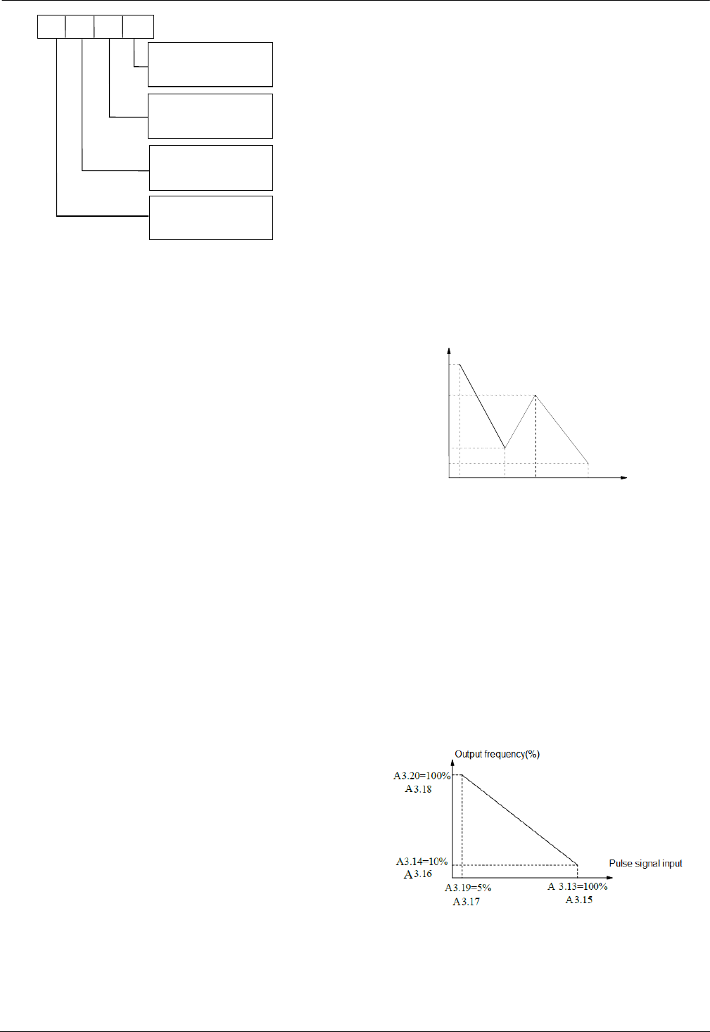
37
37
Fig.6-9 Frequency curve selection
For example, the requirements are:
1.Use the pulse signal input via terminal to set the
reference frequency;
2.Range of input signal frequency:1kHz~20kHz;
3.1kHz input signal corresponds to 50Hz reference
frequency, and 8kHz input signal corresponds to 10Hz
reference frequency, 12kHz input signal corresponds to
40Hz reference frequency,20kHz input signal
corresponds to 5Hz reference frequency.
According to the above requirements, the parameter
settings are:
1)A0.02=4,select pulse input to set the reference
frequency.
3)A3.00=3000,select curve 4.
4)A6.10=20.0kHz,set the Max. input pulse frequency
to 20kHz.
5)A3.13 =20÷20×100 %=100.0 %,the maximum
reference of curve 4 is actually the percentage of 20kHz
to 20kHz(A6.10).
6)A3.14=5.00Hz÷A0.08*100%, set the percentage of
frequency that corresponds to the Max. reference
(20kHz pulse signal).
7)A3.15=12÷20×100%=60.0%,the reference of
inflection 2 of curve 4 is actually the percentage of
12kHz to 20kHz(A6.10).
8)A3.16=40.00Hz÷A0.08*100%,set the percentage of
frequency that corresponds to the reference of inflection
2 of curve 4 (12kHz pulse signal).
9)A3.17=8÷20×100%=40.0%,the reference of
inflection 1 of curve 4 is actually the percentage of 8kHz
to 20kHz(A6.10).
10)A3.18=10.00Hz÷A0.08*100%,set the percentage
of frequency that corresponds to the reference of
inflection 1 of curve 4 (8kHz).
11)A3.19=1÷20×100%=5.0%,the Min. reference of
curve 4 is actually the percentage of 1kHz to
20khz(A6.10)
12)A3.20=50.00Hz÷A0.08*100%,set the percentage
of frequency that corresponds to the Min. reference
(1kHz pulse signal).
Fig.6-10 Pulse signal input 1
If there is no setting of inflection point in the 3rd
requirement,means to change the requirement as 1kHz
input signal corresponds to 50Hz reference frequency,
and 20kHz input signal corresponds to 5Hz reference
frequency.Then we can set the inflection point 1 the
same as Min. reference(A3.17=A3.19,A3.18=A3.20)
and inflection point 2 the same as Max. reference(A3.13
=A3.15,A3.14=A3.16).As shown in Fig.6-11.
Fig.6-11 Pulse signal input 2
A3.13
A3.15 A3.17 A3.19
Pulse signal input
Output frequency (%)
.
A3.14=10%
5% 40%6
0 %1 0 0 %
A3.16=80%
A3.18=20%
A3.20=100%
AI1
Curve selection
0:Curve 1 1:Curve 2
AI2
Curve selection
AI3 Curve selection
PULSE Curve selection
A
B
C
D
2:Curve 3 3:Curve 4
0:Curve 1 1:Curve 2
2:Curve 3 3:Curve 4
0:Curve 1 1:Curve 2
2:Curve 3 3:Curve 4
0:Curve 1 1:Curve 2
2:Curve 3 3:Curve 4
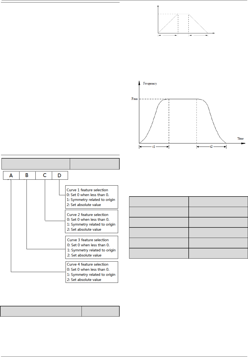
38
38
Note:
1.If user set the reference of inflection point 2 of curve
4the same as Max. reference(A3.15=A3.13),then the
drive will force A3.16=A3.14,means the setting of
inflection point 2 is invalid.If reference of inflection
point 2 is the same as reference of inflection point
1(A3.17=A3.15),then the drive will force
A3.18=A3.16,means the setting of inflection point is
invalid.If reference of inflection point 1 is the same as
Min. reference(A3.19=A3.17),then the drive will force
A3.20=A3.18,means the setting of Min. reference is
invalid.The setting of curve 1 is in the same manner.
2.The range of the actual value that corresponds to the
reference of curve 1,2,3 and 4 is 0.0%~100.0%,
corresponds to torque is 0.0%~300.0%,and
corresponds to frequency, its range is 0.0%~100.0%.
A3.21 Curve features selection 0000~2222H【0000】
6.5 Group A4
A4.00 Acc/Dec mode 0~1【0】
0: Linear Acc/Dec mode
Output frequency increases or decreases according to a
constant rate, as shown in Fig. 6-12.
Fig.6-12 Linear Acc/Dec
1: S curve Acc/Dec mode.
The output frequency accelerates and decelerates
according to S curve,as shown in Fig.6-13.
Fig.6-13 S curve Acc/Dec
S curve Acc/Dec mode can smooth acceleration and
deceleration, suitable for application like lift, conveyer
belt.
A4.01 Acc time 2 0.1~6000.0s【6.0s】
A4.02 Dec time 2 0.1~6000.0s【6.0s】
A4.03 Acc time 3 0.1~6000.0s【6.0s】
A4.04 Dec time 3 0.1~6000.0s【6.0s】
A4.05 Acc time 4 0.1~6000.0s【6.0s】
A4.06 Dec time 4 0.1~6000.0s【6.0s】
Acc time is the time taken for the motor to accelerate
from 0Hz to the maximum frequency (as set in A0.08),
see t2 in Fig.6-12. Dec time is the time taken for the
motor to decelerate from maximum frequency (A0.08)
to 0Hz, see t2 in Fig.6-12.
CV100 define three kinds of Acc/Dec time,and the
drive’s Acc/Dec time 1~4 can be selected by different
combinations of control terminals, refer to the
introductions of A6.00~A6.04 for the definitions of
terminals used to select Acc/Dec time.
Frequency
Time
Fmax
t1t 2
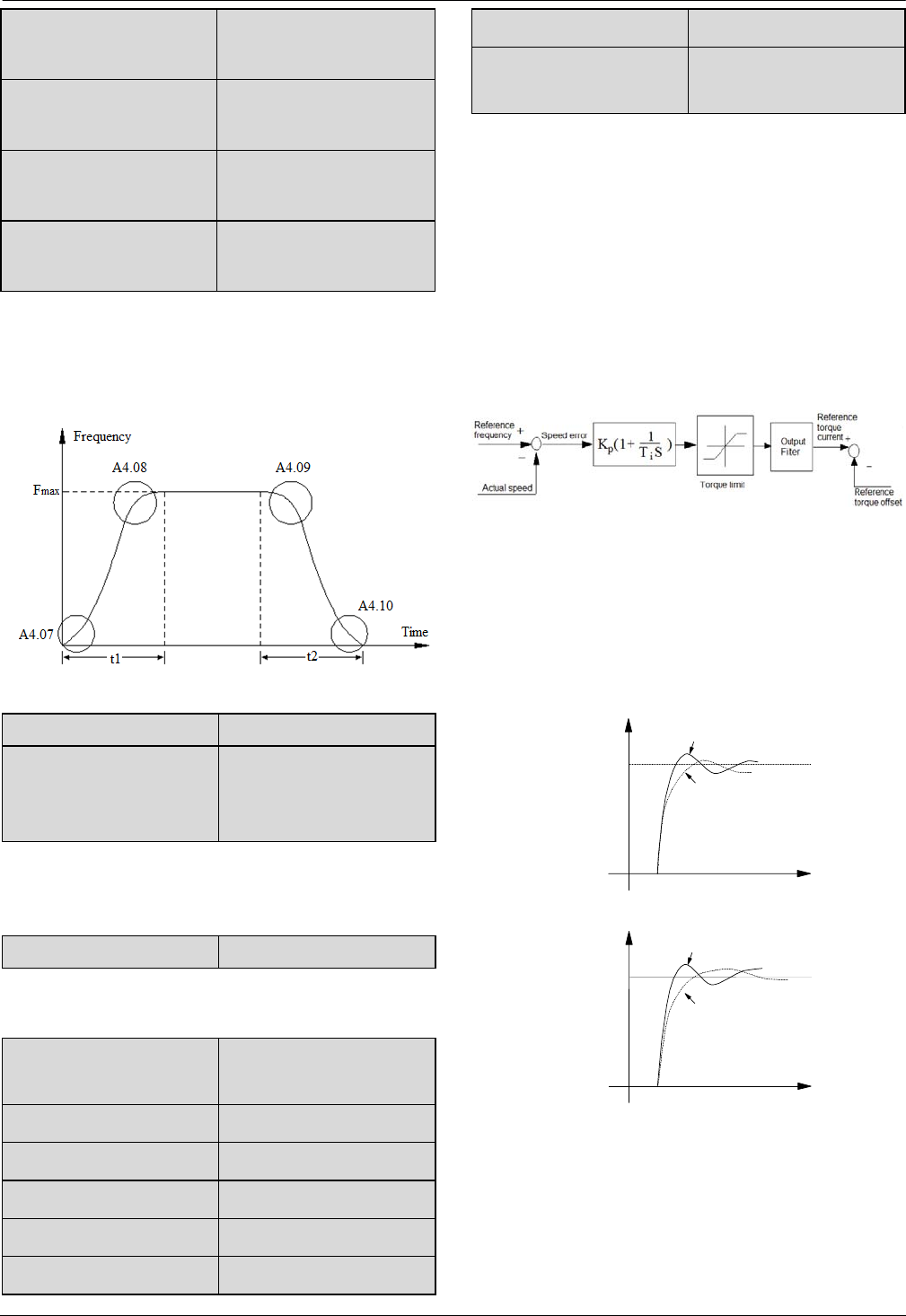
39
39
A4.07 S curve acceleration
starting time
10.0%~50.0% (Acc time)
A4.07+ A4.08≤90【20.0%】
A4.08 S curve acceleration
ending time
10.0%~70.0% (Acc time)
A4.07+ A4.08≤90【20.0%】
A4.09 S curve deceleration
starting time
10.0%~50.0% (Dec time)
A4.09+ A4.10≤90【20.0%】
A4.10 S curve deceleration
ending time
10.0%~70.0% (Dec time)
A4.09+ A4.10≤90【20.0%】
A4.07~A4.10 is only valid when A4.00 is set as 1 (S
curve Acc/Dec mode),and it must make sure
A4.07+A4.08≤90%, A4.09+ A4.10≤90%,as shown in
Fig.6-14.
Fig.6-14 Acc/Dec starting time and ending time
A4.11~ A4.21 Reserved Reserved
A4.22 Switch frequency for
Acc/Dec time 1 and
Acc/Dec time 2.
0.00~300.00Hz 【000.00】
It will use Acc/Dec time 2 when output frequency is lower
than A4.22.
A4.23~ A4.25 Reserved Reserved
6.6 Group A5
A5.00 Speed/Torque
control mode
0:Speed control mode
1:Torque control mode
A5.01 ASR1-P 0.1~200.0【20.0】
A5.02 ASR1-I 0.000~10.000s【0.200s】
A5.03 ASR1 output filter 0~8【0】
A5.04 ASR2-P 0.1~200.0【20】
A5.05 ASR2-I 0.000~10.000s【0.200s】
A5.06 ASR2 output filter 0~8【0】
A5.07 ASR1/2 switching
frequency 0~100.0%【10.0%】
The parameters A5.00~A5.07 are only valid for vector
control mode.
Under vector control mode,it can change the speed
response character of vector control through adjusting
the proportional gain P and integral time I for speed
regulator.
1.The structure of speed regulator (ASR) is shown in
Fig.6-13.In the figure, KP is proportional gain P. TI is
integral time I.
Fig.6-13 Speed regulator
When integral time is set to 0 (A5.02=0,A5.05=
0),then the integral is invalid and the speed loop is just a
proportional regulator.
2. Tuning of proportional gain P and integral time I for
speed regulator(ASR).
Fig.6-14 The relationship between step response and PI
parameters of speed regulator(ASR)
Speed
command
Proportional gain
is bigger
Proportional gain
is smaller
Speed
command
Integral time is smaller
Integral time is bigge
r
(a)
(b)
A6.10
,
A6.11
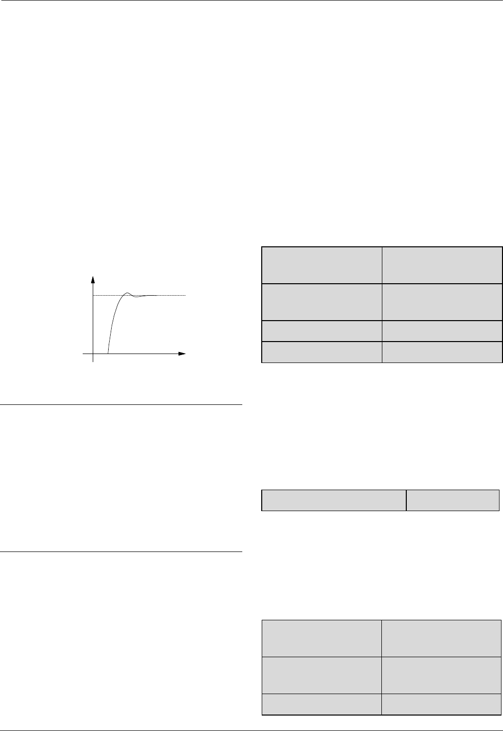
40
40
When increasing proportional gain P,it can speed up the
system’s dynamic response.But if P is too big,the system
will become oscillating.
When decreasing integral time I,it can speed up the
system’s dynamic response.But if I is too small,the
system will become overshoot and easily oscillating.
Generally, to adjust proportional gain P firstly.The value
of P can be increased as big as possible if the system
don’t become oscillating.Then adjust integral time to
make the system with fast response but small
overshoot.The speed step response curve of speed,when
set a better value to P and I parameters,is shown in
Fig.6-15.(The speed response curve can be observed by
analog output terminal AO1 and AO2,please refer to
Group A6)
Fig.6-15 The step response with better dynamic
performance
Note:
If the PI parameters are set incorrectly,it will cause
over-voltage fault when the system is accelerated to high
speed quickly(If the system doesn’t connect external
braking resistor or braking unit),that is because the
energy return under the system’s regenerative braking
when the system is dropping after speed overshoot.It can
be avoided by adjusting PI parameters
3. The PI parameters’ adjustment for speed
regulator(ASR) in the high/low speed running occasion
To set the switching frequency of ASR (A5.07) if the
system requires fast response in high and low speed
running with load.Generally when the system is running
at a low frequency,user can increase proportional gain P
and decrease integral time I if user wants to enhance the
dynamic response.The sequence for adjusting the
parameters of speed regulator is as following:
1)Select a suitable switching frequency( A5.07).
2)Adjust the proportional gain (A5.01) and integral
time(A5.02) when running at high speed,ensure the
system doesn’t become oscillating and the dynamic
response is good.
3)Adjust the proportional gain (A5.04) and integral
time(A5.05) when running at low speed, ensure the
system doesn’t become oscillating and the dynamic
response is good.
4. Get the reference torque current through a delay filter
for the output of speed regulator.A5.03 and A5.06 are
the time constant of output filter for ASR1 and ASR2.
A5.08 Forward speed limit
in torque control mode 0.0%~+100.0%【100.0%】
A5.09 Reverse speed limit
in torque control mode 0.0%~+100.0%【100.0%】
A5.10 Driving torque limit 0.0%~+300.0%【180.0%】
A5.11 Braking torque limit 0.0%~+300.0%【180.0%】
Driving torque limit is the torque limit in motoring
condition.
Braking torque limit is the torque limit in generating
condition.
In setting value,100% is corresponding to drive’s rated
torque.
A5.12 Reference torque selector 0~4 【0】
0: Digital torque setting
1:AI1
2: AI2
3: AI3
4: Terminal DI (Pulse) setting
A5.13 Digital torque
setting -300.0%~+300.0%【0%】
A5.14 Switch point from
speed to torque 0%~+300.0%【100%】
A5.15 Delay for switch 0~1000mS【0】
Speed
Command

41
41
speed and torque
A5.16 Filter for torque
setting 0~65535mS【0】
A5.17 ACR-P 1~5000【1000】
A5.18 ACR-I 0.5~100.0mS【8.0ms】
A5.17 and A5.18 are the parameters for PI regulator of
current loop.Increasing P or decreasing I of current loop
can speed up the dynamic response of torque.Decreasing
P or increasing I can enhance the system’s stability.
Note:
For most applications, there is no need to adjust the PI
parameters of current loop,so the users are suggested to
change these parameters carefully.
6.7 Group A6
A6.00 Multi-function terminal X1 0~41【01】
A6.01 Multi-function terminal X2 0~41【02】
A6.02 Multi-function terminal X3 0~41【06】
A6.03 Multi-function terminal X4 0~41【27】
A6.04 Multi-function terminal X5 0~41【28】
A6.05 Multi-function terminal X6 0~41【29】
A6.06 Multi-function terminal X7 0~41【00】
A6.07: Reserved
The functions of multi-function input terminal X1~X7
are extensive. You can select functions of X1~X7
according to your application by setting A6.00~FA.06.
Refer to Table 6-1.
Note:
Can not set the same function for different terminals. For
example, if X1 is set as forward function【01】, then the
others terminals can not be set as the same function.
Table 6-1 Multi-function selection
Setting Function Setting Function
0 No function 1 Forward
Setting Function Setting Function
2 Reverse 3 Forward jog
operation
4 Reverse jog
operation 5 3-wire operation
control
6 External RESET
signal input 7 External fault
signal input
8 External interrupt
signal input 9 Drive operation
prohibit
10 External stop
command 11 DC injection
braking command
12 Coast to stop 13 Frequency ramp
up (UP)
14 Frequency ramp
down (DN) 15 Switch to panel
control
16 Switch to terminal
control 17 Reserved
18
Main reference
frequency via AI1 19 Main reference
frequency via AI2
20 Reserved 21
Main reference
frequency via DI
22
Auxiliary reference
frequency invalid 23 Reserved
24 Reserved 25 Reserved
26 Reserved 27 Preset frequency 1
28 Preset frequency 2 29 Preset frequency 3
30 Preset frequency 4 31 Acc/Dec time 1
32 Acc/Dec time 2 33 Multi-closed loop
reference 1
34
Multi-closed loop
reference 2 35 Multi-closed loop
reference 3
36
Multi-closed loop
reference 4 37 Forward prohibit
38 Reverse prohibit 39 Acc/Dec prohibit
40
Process closed loop
prohibit 41
Switch speed
control and torque
control

42
42
Setting Function Setting Function
42
Main frequency
switch to digital
setting
43 PLC pause
44 PLC prohibit 45 PLC stop memory
clear
46 Reserved 47 Reserved
Introductions to functions listed in Table 6-1:
1: Forward.
2: Reverse.
3~4: Forward/reverse jog operation.
They are used jog control of terminal control mode.The
jog operation frequency,jog interval and jog Acc/Dec
time are defined by A2.04~A2.05,A4.05~A4.06.
5: 3-wire operation control.
They are used in operation control of terminal control
mode.Refer to A6.09.
6: External RESET signal input.
The drive can be reset via this terminal when the drive
has a fault. The function of this terminal is the same with
that of RST on the panel.
7: External fault signal input.
If the setting is 7, the fault signal of external equipment
can be input via the terminal, which is convenient for the
drive to monitor the external equipment. Once the drive
receives the fault signal, it will display “E015”.
8: External interrupt signal input
If the setting is 8, the terminal is used to cut off the
output and the drive operates at zero frequency when the
terminal is enabled. If the terminal is disabled, the drive
will start on automatically and continue the operation.
9: Drive operation prohibit.
If terminal is enabled, the drive that is operating will
coast to stop and is prohibited to restart. This function is
mainly used in application with requirements of safety
protection.
10: External stop command.
This stopping command is active in all control
modes.When terminal 35 is enabled, the drive will stop
in the mode defined in A1.05.
11: DC injection braking command.
If the setting is 11, the terminal can be used to perform
DC injection braking to the motor that is running so as to
realize the emergent stop and accurate location of the
motor. Initial braking frequency, braking delay time and
braking current are defined by A1.06~A1.08. Braking
time is the greater value between A1.09 and the effective
continuous time defined by this control terminal.
12: Coast to stop.
If the setting is 12, the function of the terminal is the
same with that defined by A1.05. It is convenient for
remote control.
13~14: Frequency ramp UP/DN.
If the setting is 13~14, the terminal can be used to
increase or decrease frequency. Its function is the same
with ▲ and ▼ keys on the panel, which enables remote
control. This terminal is enabled when A0.02=0 and
A0.04=1. Increase or decrease rate is determined by
A2.02 and A2.03.
15: Switch to panel control.
It is used to set the control mode as panel control.
16: Switch to terminal control
It is used to set the control mode as terminal control.
17: Reserved.
18: Main reference frequency via AI1
19: Main reference frequency via AI2
20: Main reference frequency via AI3
21: Main reference frequency via DI
Main reference frequency will switch to set via
AI1,AI2,AI3 or DI when the terminal activate.
22: Auxiliary reference frequency invalid.
Auxiliary reference frequency is invalid when the
terminal activate.
23~26: Reserved.
27~30: Preset frequency selection.
Up to 15 speed references can be set through different
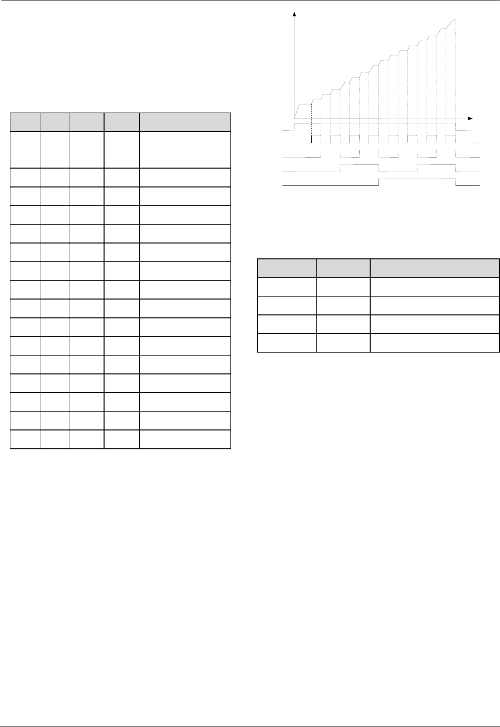
43
43
ON/OFF combinations of these terminals K4,K3,K2 and
K1. Refer to Group C0 to set the value of Preset
frequency. Switch Acc/Dec time along with multi-step
speed(Terminal of Preset frequency 1 is closed, terminal
of Acc/Dec time selection is closed).
Table 6-2 On/Off combinations of terminals
K4 K3 K2 K1 Frequency setting
OFF OFF OFF OFF Common operating
frequency
OFF OFF OFF ON Preset frequency1
OFF OFF ON OFF Preset frequency 2
OFF OFF ON ON Preset frequency 3
OFF ON OFF OFF Preset frequency 4
OFF ON OFF ON Preset frequency 5
OFF ON ON OFF Preset frequency 6
OFF ON ON ON Preset frequency 7
ON OFF OFF OFF Preset frequency 8
ON OFF OFF ON Preset frequency 9
ON OFF ON OFF Preset frequency 10
ON OFF ON ON Preset frequency 11
ON ON OFF OFF Preset frequency 12
ON ON OFF ON Preset frequency 13
ON ON ON OFF Preset frequency 14
ON ON ON ON Preset frequency 15
The frequency references will be used in multiple speed
operation. Following is an example:
Definitions of terminals X1, X2,X3 and X4 as
following:
After setting A6.00 to 27, A6.01 to 28 and A6.03 to 30,
terminals X1~X4 can be used in multiple speed
operation, as shown in Fig. 6-16.
Fig.6-16 Multi-step speed operation
31~32: Acc/Dec time selection
Table 6-3 Acc/Dec time selection
Terminal 2 Terminal1 Acc/Dec time selection
OFF OFF Acc time 1/Dec time 1
OFF ON Acc time 2/Dec time 2
ON OFF Acc time 3/Dec time 3
ON ON Acc time 4/Dec time 4
Through the On/Off combinations of terminal 1and 2,
Acc/Dec time 1~4 can be selected.
33~36: Multi-voltage setting in closed loop
K4
K
K2
K3
Speed 1
Output frequency
Time
Common
command
Speed 15
Common
Operating
frequency

44
44
Table 6-4 On/Off combinations for voltage selection
Refer to C1.19~C1.33 to set the value of Preset
close-loop reference.
37: Forward prohibit.
The drive will coast to stop if the terminal activate when
running forward.If the terminal activate before the drive
run forward,the drive will run in 0Hz.
38: Reverse prohibit.
The drive will coast to stop if the terminal activate when
running reverse.If the terminal activate before the drive
run reverse,the drive will run in 0Hz.
39: Acc/Dec prohibit
If the setting is 15, the terminal can make the motor
operate at present speed without being influenced by
external signal (except stopping command).
40: Process closed loop prohibit
Forbid process closed loop control.
41: Switch speed control and torque control
Switch speed control mode and torque control mode.
42: Main frequency switch to digital setting
Switch the main frequency selector to digital setting.
43: PLC pause
Pause PLC function control.
44: PLC prohibit
Forbid PLC function running.
45: PLC stop memory clear
Clear the memory which store the steps before PLC
function stop.
46~47: Reserved.
A6.08 Terminal filter 0~500ms【10ms】
A6.08 is used to set the time of filter for input
terminals.When the state of input terminals change, it
must keep the state for the filter time,or the new state
won’t be valid.
A6.09 Terminal control mode
selection 0~4【0】
This parameter defines four operating modes controlled
by external terminals.
0: 2-wire operating mode 1
K4 K3 K2 K1 Voltage setting
OFF OFF OFF OFF Determined by
C1.01
OFF OFF OFF ON Preset close-loop
reference 1
OFF OFF ON OFF Preset close-loop
reference 2
OFF OFF ON ON Preset close-loop
reference 3
OFF ON OFF OFF Preset close-loop
reference 4
OFF ON OFF ON Preset close-loop
reference 5
OFF ON ON OFF Preset close-loop
reference 6
OFF ON ON ON Preset close-loop
reference 7
ON OFF OFF OFF Preset close-loop
reference 8
ON OFF OFF ON Preset close-loop
reference 9
ON OFF ON OFF Preset close-loop
reference 10
ON OFF ON ON Preset close-loop
reference 11
ON ON OFF OFF Preset close-loop
reference 12
ON ON OFF ON Preset close-loop
reference 13
ON ON ON OFF Preset close-loop
reference 14
ON ON ON ON Preset close-loop
reference 15
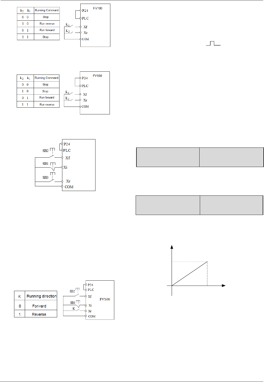
45
45
Fig.6-17 2-wire operating mode 1
1: 2-wire operating mode 2
Fig.6-18 2-wire operating mode 2
2: 3-wire operating mode 1
Fig.6-19 3-wire operating mode 1
Where:
SB1: Stop button
SB2: Run forward button
SB3: Run reverse button
Terminal Xi is the multi-function input terminal of
X1~X7.At this time, the function of this terminal should
be defined as No.5 function of “3-wire operation”.
3: 3-wire operation mode 2
Fig.6-20 3-wire operation mode 2
Where:
SB1: Stop button
SB2: Run button
Terminal Xf, Xr, Xi is the multi-function input terminal
of X1~X7. At this time, the function of this terminal
should be defined as No.1 (Forward) No.2 (Reverse)
No.5 function (3-wire operation). First, set the key SB1
in normal close status to make this function(3-wire
operation mode 2) enable. Second, press the key SB2
once to give Xf a pulse signal ( ) then the running
direction is forward, at this moment, the key K is in
normal open status. Last but not least, make the key K in
normal close status, then the running direction will be
reverse. Just need to switch the status of key K, will the
direction be changed.
4: 2-wires operation mode 3
In this mode, if drive has been already set as start by
terminal control, and the terminal is already enable, then
when drive power on, it will start immediately. Please be
carefully to use this function.
A6.10 Max. frequency of
input pulse 0.1~100.0kHz【10kHz】
This parameter is used to set the max. frequency of input
pulse when X7 is defined as pulse input.
A6.11 Center point of pulse
setting selection 0~2【0】
This parameter defines different modes of center point
when X7 is defined as pulse input.
0: No center point.As shown in Fig.6-21.
Fig.6-21 No center point mode
All the corresponding values of pulse input frequency
are positive.
1: Center point mode 1.
A 6 . 1 0
0Frequency
FV100
Corresponding
value

46
46
Fig.6-22 Center point mode 1
There is a center point in pulse input.The value of the
center point is a half of max.frequency of input
pulse(A6.10).The corresponding value is positive when
the input pulse frequency is less than center point.
2: Center point mode 2.
There is a center point in pulse input.The value of the
center point is a half of max.frequency of input
pulse(A6.10).The corresponding value is positive when
the input pulse frequency is greater than center point.
Fig.6-23 Center point mode 2
A6.12 Filter of pulse input 0.00~10.00s【0.05s】
This parameter defines the filter time of pulse input. The
bigger of the filter time,the slower of the frequency
changing rate of pulse input.
A6.13 Input terminal’s
positive and negative logic 00~FFH【00H】
Fig.6-24 terminal’s positive and negative logic
A6.13 defines the input terminal’s positive and negative
logic
Positive logic: Terminal Xi is enabled if it is connected
to the common terminal;
Negative logic: Terminal Xi is disabled if it is connected
to the common terminal;
If the bit is set at 0, it means positive logic; if set at 1, it
means negative logic. For example:
If X1~X4 are required to be positive logic, X5~X7 are
required to be negative logic, settings are as following:
Logic status of X4~X1 is 0000, and the hex value is 0.
Logic status of X7~X5 is 111, and the hex value is 7.
So A6.13 should be set as 70. Refer to Table 6-5.
Table 6-5 Conversion of binary code and hex value
Binary settings Hex value
(Displaying of LED)
BIT3 BIT2 BIT1 BIT0
0 0 0 0 0
0 0 0 1 1
0 0 1 0 2
0 0 1 1 3
0 1 0 0 4
0 1 0 1 5
0 1 1 0 6
0 1 1 1 7
1 0 0 0 8
1 0 0 1 9
1 0 1 0 A
1 0 1 1 B
1 1 0 0 C
1 1 0 1 D
1 1 1 0 E
1 1 1 1 F
Note:
Factory setting of all the terminals is positive logic.
A6.14 Bi-direction open-collector
output terminal Y1 0~20【0】
A6
. 10
0
2
10 . 6
A Frequency
A6 . 10
0
2
10 .
6
A
Corresponding
value
Frequency
Corresponding
value

47
47
A6.15 Reserved
A6.16 Output functions of relay R1 Same as A6.14
A6.17 Reserved
Refer to chapter 3 for the output characteristics of Y1
that are bi-direction open-collector output terminal and
the relay’s output terminal. Table 6-6 shows the
functions of the above 2 terminals. One function can be
selected repeatedly.
Table 6-6 Functions of output terminals
Setting Function Setting Function
0 Drive running
signal (RUN) 1 Frequency arriving
signal (FAR)
2
Frequency
detection
threshold
(FDT1)
3 Frequency detection
threshold (FDT2)
4 Reserved 5 Low voltage
lock-up signal (LU)
6
External
stopping
command
(EXT)
7 High limit of
frequency (FHL)
8
Lower limit of
frequency
(FLL)
9 Zero-speed running
10 Reserved 11 Reserved
12
PLC running
step finish
signal
13 PLC running cycle
finish signal
14 Reserved 15 Drive ready (RDY)
16 Drive fails 17 Reserved
18 Reserved 19 Torque limiting
20 Drive running
forward/reverse
The instructions of the functions in Table 6-6 as
following:
0: Drive running signal (RUN)
When the drive is in operating status, there will be
running indication signal output by this terminal.
1: Frequency arriving signal (FAR)
See A6.19.
2: Frequency detection threshold (FDT1)
See A6.20~A6.21.
3: Frequency detection threshold (FDT2)
See A6.22~A6.23.
4: Reserved.
5: Low voltage lock-up signal (LU)
The terminal outputs the indicating signal if the DC bus
voltage is lower than the low voltage limit, and the LED
displays “P.oFF”.
6: External stopping command (EXT)
The terminal outputs the indicating signal if the drive
outputs tripping signal caused by external fault (E015).
7: High limit of frequency (FHL)
The terminal outputs the indicating signal if the preset
frequency is higher than upper limit of frequency and the
operating frequency reaches the upper limit of
frequency.
8: Lower limit of frequency (FLL)
The terminal outputs the indicating signal if the preset
frequency is higher than lower limit of frequency and the
operating frequency reaches the lower limit of frequency
9: Zero-speed running
The terminal outputs the indicating signal if the drive’s
output frequency is 0 and the drive is in operating status.
10~11:Reserved.
12: PLC running step finish signal
In PLC running mode,when it finishes the current step,it
will output signal(Single pulse with width 500ms).
13: PLC running cycle finish signal
In PLC running mode,when it finishes one cycle, it will
output signal(Single pulse with width 500ms).
14. Reserved
15: drive ready (RDY)
If RDY signal is output, it means the drive has no fault,
its DC bus voltage is normal and it can receive starting
command.
16: Drive fails
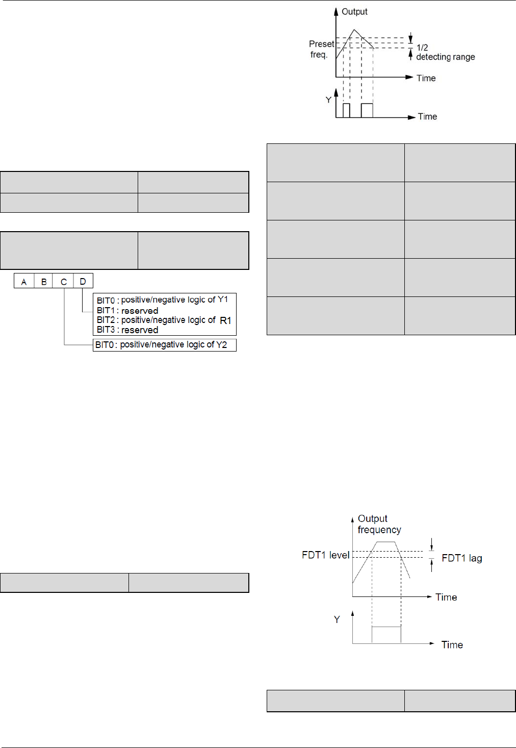
48
48
The terminal outputs the indicating signal if the drive
has faults.
17~18: Reserved.
19:Torque limiting
The terminal outputs the indicating signal if the torque
reach drive torque limit or brake torque limit.
20:Drive running forward/reverse
The terminal outputs the indicating signal according to
the drive’s current running direction.
A6.18 Delay of relay R1 0.1~10S【0.1S】
A6.19 Reserved
A6.20 Output terminal’s
positive and negative logic 00~1FH【00H】
Fig.6-25 Output terminal’s positive and negative logic
A6.18 defines the output terminal’s positive and
negative logic .
Positive logic: Terminal is enabled if it is connected to
the common terminal;
Negative logic: Terminal is disabled if it is connected
to the common terminal;
If the bit is set at 0, it means positive logic; if set at 1, it
means negative logic.
Note: A6.18 is only valid when the function of terminal R1
is activated.
A6.19 Reserved Reserved
As shown in Fig. 6-26, if the drive’s output frequency is
within the detecting range of preset frequency, a pulse
signal will be output.
Fig.6-26 Frequency arriving signal
A6.21 Frequency arriving
signal (FAR)
0.00~300.00Hz
【002.50】
A6.22 FDT1 level
0.00~300.00Hz
【050.00】
A6.23 FDT1 lag
0.00~300.00Hz
【001.00】
A6.24 FDT1 lag
0.00~300.00Hz
【050.00】
A6.25 FDT2 lag
0.00~300.00Hz
【001.00】
A6.22~A6.23 is a complement to the No.2 function in
Table 6-6. A6.24~A6.25 is a complement to the No.3
function in Table 6-6. Their functions are the same.Take
A6.22~A6.23 for example:
When the drive’s output frequency reaches a certain
preset frequency (FDT1 level), it outputs an indicating
signal until its output frequency drops below a certain
frequency of FDT1 level (FDT1 level-FDT1 lag), as
shown in Fig. 6-27.
Fig.6-27 FDT level
A6.26 Virtual terminal setting 0~007FH【00h】
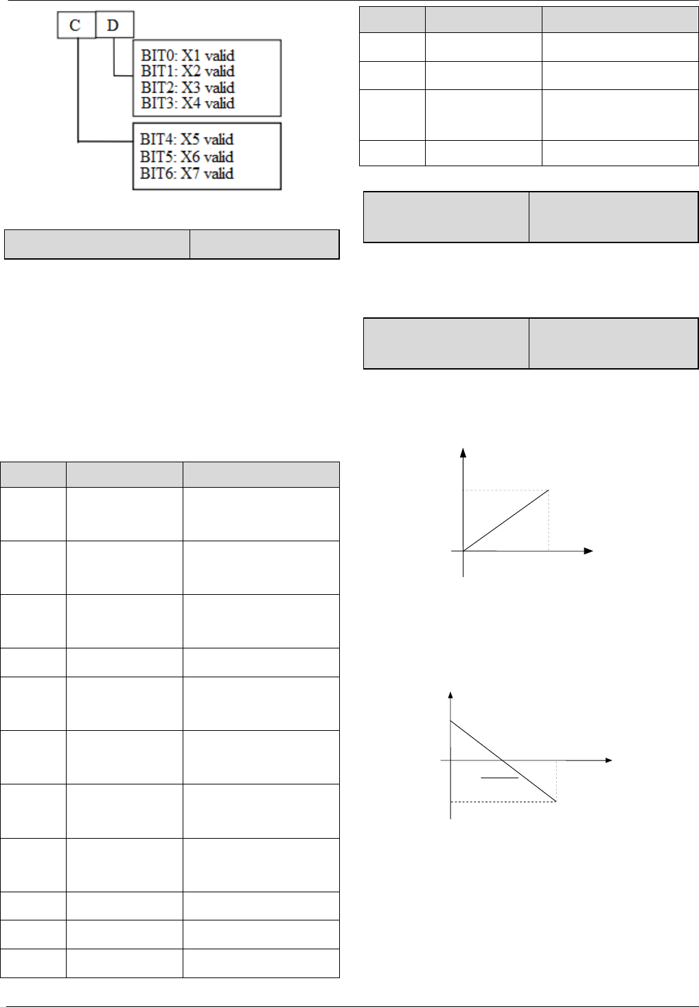
49
49
A6.27 Y2 terminal output 0~100【000】
0~50: Y2 is used as Y terminal output, its function is the
same as Table 6-6.
51~88: Y2 function.
Pulse frequency frequency of Y2:0~Max. pulse output
frequency(Defined in A6.26).
The linear relationship between the displaying range and
the output values of Y2 is shown as Table 6-7.
Table 6-7 Displaying range of Y2 terminal
Setting Function Range
51 Output frequency
0~Max. Output
frequency
52 Preset frequency
0~Max. output
frequency
53 Preset frequency
(After Acc/Dec)
0~Max. output
frequency
54 Motor speed
0~Max. speed
55 Output current
Iei
0~2 times of motor’s
rated current
56 Output current
Iem
0~3 times of motor’s
rated current
57 Output torque
0~3 times of motor’s
rated torque
58 Output voltage
0~1.2 times of drive’s
rated voltage
60 Bus voltage
0~800V
61 AI1 Voltage
-10V~10V
62 AI2 Voltage
-10V~10V
Setting Function Range
63 AI3 Voltage
-10V~10V
64 DI pulse input
0~100KHz
65 Percentage of
host computer 0~4095
66~88 Reserved Reserved
A6.28 Max. output pulse
frequency 0.1~100kHz【10.0】
This parameter defines the permissible maximum pulse
frequency of Y2.
A6.29 Center point of
pulse output selection 0~2【0】
This parameter defines different center point mode of Y2
pulse output.
0:No center point. Shown as following figure:
Fig.6-28 No center point mode
All the corresponding value of pulse output
Frequency are positive.
1:Center point mode 1.Shown as following figure.
Fig.6-29 Center point mode 1
There is a center point in pulse output.The value of the
cent point is a half of max. output pulse frequency
(A6.28).The corresponding value is positive when the
output pulse frequency is less than center point.
2: Center point mode 2
A 6 . 2 6
0
Corresponding
value
2
26.6
A
A 6 . 2 6
0
Corresponding
value
Frequency
Frequency
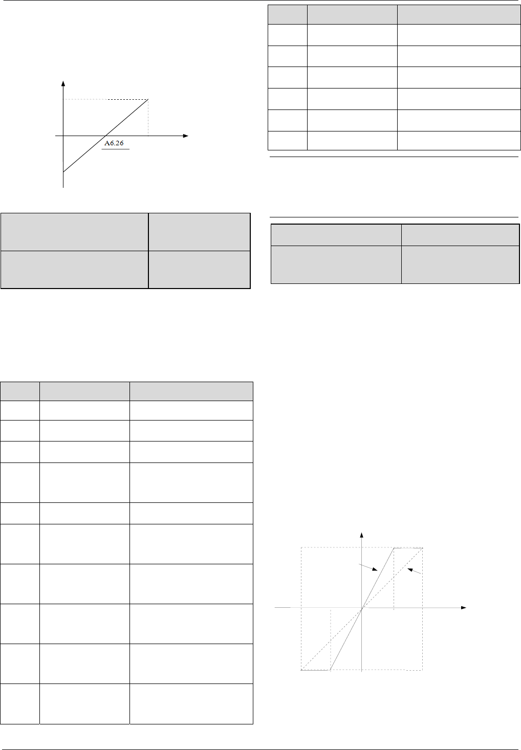
50
50
There is a center point in pulse output.The value of the
center point is a half of max. output pulse frequency
(A6.28).The corresponding value is positive when the
input pulse frequency is greater than center point.
Fig.6-30 Center point mode 2
A6.30 Functions of terminal
AO1 0~36【0】
A6.31 Functions of terminal
AO2 0~36【0】
Refer to section 4.2 for the output characteristics of AO1
and AO2.
The relationship between the displaying range and the
output values of AO1 and AO2 is shown as Table 6-8
Table 6-8 Displaying range of Analog output
Setting Function Range
0 No function No function
1 Output frequency
0~Max. output frequency
2 Preset frequency
0~Max. output frequency
3
Preset frequency
(After Acc/Dec) 0~Max. output frequency
4 Motor speed 0~Max. speed
5 Output current
0~2 times of drive’s
rated current
6 Output current
0~2 times of motor’s
rated current
7 Output torque
0~3 times of motor’s
rated torque
8 Output torque
current
0~3 times of motor’s
rated torque
9 Output voltage
0~1.2 times of drive’s
rated voltage
Setting Function Range
10 Bus voltage 0~800V
11 AI1 0~Max. analog input
12 AI2 0~Max. analog input
13 AI3 0~10V
14 DI pulse input 0~Max. pulse input
Others Reserved Reserved
Note:
The external resistor is advised to be lower than 400Ω
when AO output current signal.
A6.32 Gain of AO1 0.0~200.0%【100.0%】
A6.33 Zero offset calibration
of AO1
-100.0~100.0%【0.0%】
For the analog output AO1 and AO2, adjust the gain if
user need to change the display range or calibrate the
gauge outfit error.
100% of zero offset of analog output is corresponding to
the maximum output (10V or 20mA).Take output
voltage for example,the relationship between the value
before adjustment and with after adjustment is as
following:
AO output value=(Gain of AO)×(value before
adjustment)+(Zero offset calibration)×10V
The relationship curve between analog output and gain
and between analog output and zero offset calibration
are as Fig.6-31 and Fig.6-32.
Fig.6-31 Relationship curve between analog
output and gain
A
6 . 3 0 = 1 0 0 %
A 6.30=200%
Value before adjustment(V)
Value after adjustment(V)
1 0 -10
10
-10
5
-5
0
A6. 26
0
2
26 .6 A
Corresponding
value
Frequency

51
51
Fig.6-32 The relationship curve between analog
output and zero offset
Note:
The parameters of gain and zero offset calibration affect
the
analog output all the time when it is changing.
A6.34 Gain of AO2 0.0~200.0%【100.0%】
A6.35 Zero offset
calibration of AO2
-100.0~100.0%【0.0%】
The functions of analog output AO2 are totally the same
as AO1.
A6.36 AI1 filter 0.01~10.00s【0.05】
A6.37 AI2 filter 0.01~10.00s【0.05】
A6.38 AI3 filter 0.01~10.00s【0.05】
A6.36~A6.38 define the time constant of AI filter.The
longer the filter time,the stronger the anti-interference
ability,but the response will become slower.The shorter
the filter time,the faster the response,but the
anti-interference ability will become weaker.
A6.39 Analog input zero offset
calibration
0~1【0】
0: Disable
1: Enable
Note:
Before the analog input zero offset calibration is
enable,it needs to make sure there is no wiring in analog
input terminal or the analog input terminal is connected
to GND.
A6.40 AI1 gain 0.00~200.00%
【110.00%】
A6.41 AI2 gain 0.00~200.00%
【110.00%】
A6.42 AI3 gain 0.00~200.00%
【110.00%】
AI gain is used for the relationship between analog input
and internal value.When increasing the AI gain, then the
corresponding internal value will be increased.When
decreasing the AI gain, then the corresponding internal
value will be decreased. Take AI1 for example, if the
input AI1 is 10V but detecting value of AI1 is 8V,
increasing the AI1 gain can make it to 10V.
A6.43~A6.56 Reserved
6.8 Group A7
A7.00 PG type 0~3【0】
This parameter defines the type of encoder.
0:ABZ incremental type
1:UVW incremental type
2~3:Reserved.
A7.01 Number of pulses per
revolution of PG 0~10000【2048】
A7.01 is used to set the number of pulses per revolution
of PG(PPR).
Note:
A7.01 must be set correctly when the drive run with
speed sensor,or the motor can’t run normally.
A7.02 Direction of PG 0~1【0】
0:A phase lead B phase 1:B phase lead A phase
A phase lead B phase when motor run forward.B phase
lead A phase when motor run reverse.If the direction
which decided by the wiring sequence between interface
Value before adjustment(V)
Value after adjustment(V)
1 0 -1 0
1 0
-1 0
5
5
A 6 . 3 1 = 0
A 6 . 3 1 = 5 0 %
0
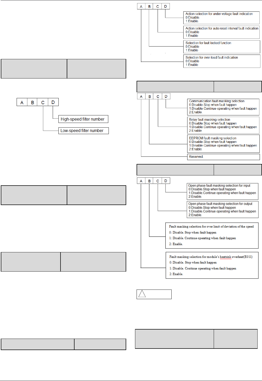
52
52
board and PG is the same as the direction which decided
by the wiring sequence between drive and motor,then set
this parameter as 0 (Forwards),or set it as 1 (Reverse).
By changing this parameter,the user can change the
direction without re-wiring.
A7.03 Encoder signal filter
number 0~99H【30H】
This parameter defines the filter number of feedback
speed.
Increase the low-speed filter number if there is current
noise when running at low speed,or decrease the
low-speed filter number to enhance the system’s
response.
A7.04 PG disconnection
detecting time 0~10s【0】
This parameter defines the continuous detecting time for
disconnection fault of PG.
When set A7.04 to 0, then the drive doesn’t detect the
PG disconnection and the fault E025 is masking.
A7.05 Reduction rate of
motor and encoder 0.001~65.535【1.000】
This parameter should be set to 1 when the encoder is
connected to the motor axis directly.Or if there is
reduction rate between motor axis and encoder,then
please set this parameter according to the actual
situation.
6.9 Group A8
A8.00 Protective action of relay 0~1111H【0000】
A8.01 Fault masking selection 1 0~2222H【2000】
A8.02 Fault masking selection 2 0~2222H【0000】
Please set the fault masking selection
function carefully, or it may cause worse accident,bodily
injury and property damage.
A8.03 Motor overload protection
mode selection 0、1、2【1】
0: Disabled
Attention!
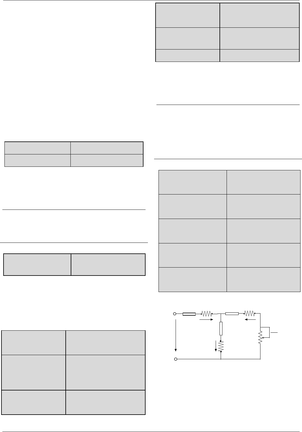
53
53
The overload protection is disabled. Be careful to use
this function because the drive will not protect the motor
when overload occurs.
1: Common motor (with low speed compensation)
Since the cooling effects of common motor deteriorates
at low speed (below 30Hz), the motor’s overheat
protecting threshold should be lowered, which is called
low speed compensation.
2: Variable frequency motor (without low speed
compensation) The cooling effects of variable frequency
motor is not affected by the motor’s speed, so low speed
compensation is not necessary.
A8.04 Auto reset times 0~100【0】
A8.05 Reset interval 2.0~20.0s【5.0s】
Auto reset function can reset the fault in preset times and
interval. When A8.04 is set to 0, it means “auto reset” is
disabled and the protective device will be activated in
case of fault.
Note:
The IGBT protection (E010) and external equipment
fault (E015) cannot be reset automatically.
A8.06 Fault locking
function selection. 0~1【0】
0:Disable.
1:Enable.
6.10 Group b0
b0.00 Rated power
0.4~999.9kW【dependent on
drive’s model】
b0.01Rated voltage
0~rated voltage of drive
【dependent on drive’s
model】
b0.02 Rated current
0.1~999.9A【dependent on
drive’s model】
b0.03 Rated frequency
1.00 ~300.00Hz 【dependent
on drive’s model】
b0.04 Number of
polarities of motor 2~24【4】
b0.05 Rated speed 0~60000RPM【1440RPM】
These parameters are used to set the motor’s parameters.
In order to ensure the control performance, please set
b0.00~b0.05 with reference to the values on the motor’s
nameplate.
Note:
The motor’s power should match that of the
drive.Generally the motor’s power is allowed to be
lower than that of the drive by 20% or bigger by 10%,
otherwise the control performance cannot be ensured.
b0.06 Resistance of
stator %R1
0.00~50.00%【dependent
on drive’s model】
b0.07 Leakage
inductance %Xl
0.00~50.00%【dependent
on drive’s model】
b0.08 Resistance of
rotor %R2
0.00~50.00%【dependent
on drive’s model】
b0.09 Exciting
inductance %Xm
0.0~2000.0%【dependent
on drive’s model】
b0.10 Current without
load I0
0.1~999.9A【dependent
on drive’s model】
See Fig. 6-33 for the above parameters.
R
1
jX
11
R
2
jX
21
I
1
I
2
I
0
X
m
U
1
1-S
S R
2
Fig. 6-33 Motor’s equivalent circuit
In Fig. 6-33, R1, X1l, R2, X2l, Xm and I0 represent
stator’s resistance, stator’s leakage inductance, rotor’s
resistance, rotor’s leakage inductance, exciting
inductance and current without load respectively. The

54
54
setting of b0.07 is the sum of stator’s leakage inductance
and rotor’s inductance.
The settings of b0.06 ~b0.09 are all percentage values
calculated by the formula below:
%% 100
)3/(
IV
R
R
(1)
R: Stator’s resistance or rotor’s resistance that is
converted to the rotor’s side;
V: Rated voltage;
I: Motor’s rated current
Formula used for calculating inductance (leakage
inductance or exciting inductance):
%% 100
)3/(
IV
X
X
(2)
X: sum of rotor’s leakage inductance and stator’s
leakage inductance (converted to stator’s side) or the
exciting inductance based on base frequency.
V: Rated voltage;
I: Motor’s rated current
If motor’s parameters are available, please set
b0.06~b0.09 to the values calculated according to the
above formula. b0.10 is the motor current without
load,the user can set this parameter directly.
If the drive performs auto-tuning of motor’s
parameters,the results will be written to b0.06~b0.10
automatically.After motor power (b0.00) is changed, the
drive will change b0.02~b0.10 accordingly(b0.01 is the
rated voltage of motor,user need to set this parameter by
manual according to the value on the motor’s
nameplate.)
b0.11 Auto-tuning 0~3【0】
0: Auto-tuning is disabled
1: Stationary auto-tuning (Start auto-tuning to a
standstill motor)
Values on the motor’s nameplate must be input correctly
before starting auto-tuning (b0.00 ~b0.05 ).When
starting auto-tuning to a standstill motor, the stator’s
resistance (%R1), rotor’s resistance (%R2) and the
leakage inductance (%X1) will be detected and written
into b0.06、b0.07 and b0.08 automatically.
2: Rotating auto-tuning
Values on the motor’s nameplate must be input correctly
before starting auto-tuning (b0.00 ~b0.05 ).When
starting a rotating auto-tuning, the motor is in standstill
status at first, and the stator’s resistance (%R1), rotor’s
resistance (%R2) and the leakage inductance (%X1) will
be detected, and then the motor will start rotating,
exciting inductance (%Xm and I0 will be detected. All
the above parameters will be saved in b0.06、b0.07、
b0.08、b0.09 and b0.10 automatically.After auto-tuning,
b0.05 will be set to 0 automatically.
Auto-tuning procedures:
1). A0.13 (Torque boost of motor 1) is suggested to set
as 0.
2). Set the parameters b0.00 (Rated power), b0.01
(Rated voltage), b0.02 (Rated current), b0.03 (Rated
frequency), b0.04 (Number of polarities of motor ) and
b0.05 (Rated speed) correctly;
3). Set the parameter A0.10 correctly.The setting value
of A0.10 can’t be lower than rated frequency.
4). Remove the load from the motor and check the
Safety when set the parameter b0.11 as 2.
5). Set b0.11 to 1 or 2, press ENTER, and then press
RUN to start auto-tuning;
6). When the operating LED turns off, that means the
auto-tuning is over.
3:Reserved.
Note:
1.When setting b0.11 to 2, Acc/Dec time can be
increased if over-current or over-voltage fault occurs in
the auto-tuning process;
2.When setting b0.11 to 2, the motor’s load must be
removed first before starting rotating auto-tuning;
3. The motor must be in standstill status before starting
the auto-tuning, otherwise the auto-tuning cannot be
executed normally;
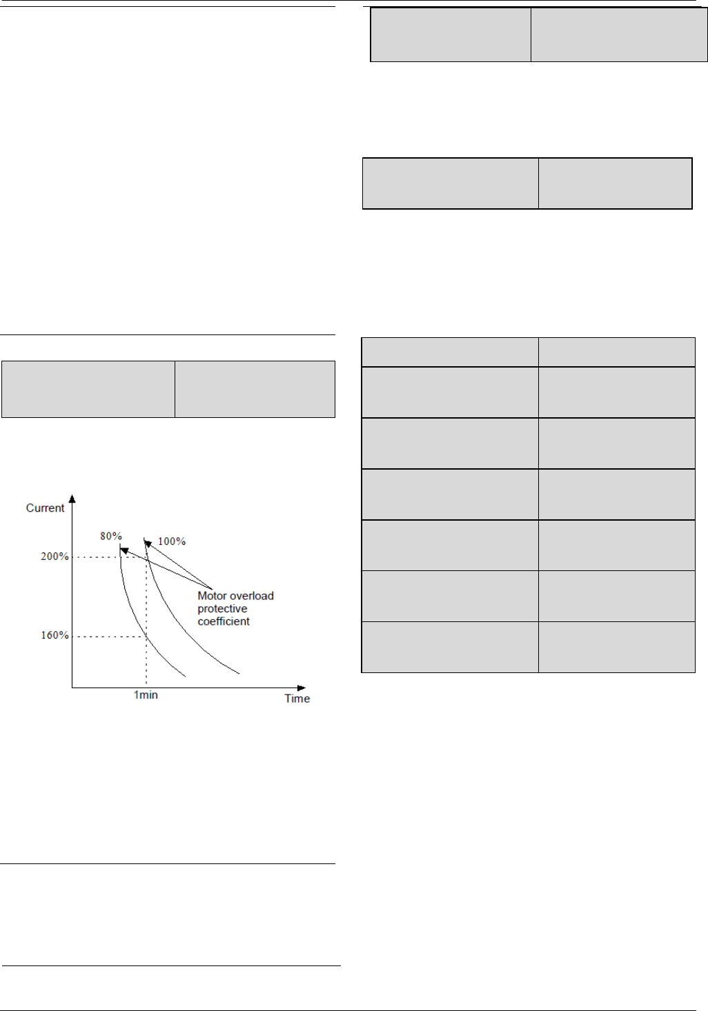
55
55
4. In some applications, for example, the motor cannot
break away from the load or if you have no special
requirement on motor’s control performance, you can
select stationary auto-tuning. You can also give up the
auto-tuning. At this time, please input the values on the
motor’s nameplate correctly .
5. If the auto-tuning cannot be applied and the correct
motor’s parameters are available, the user should input
the values on the motor’s nameplate correctly
(b0.00~b0.05), and then input the calculated values
(b0.06~b0.10). Be sure to set the parameters correctly.
6. If auto-tuning is not successful, the drive will alarm
and display fault code E024.
b0.12 Motor’s overload
protection coefficient
20.0%~110.0%
【100.0%】
In order to apply effective overload protection to
different kinds of motors, the Max. output current of the
drive should be adjusted as shown in Fig. 6-34.
Fig.6-34 Motor’s overload protection coefficient
This parameter can be set according to the user’s
requirement. In the same condition, set b0.12 to a lower
value if the user need fast protection for overload of
motor, otherwise set it to a bigger value.
Note:
If the motor’s rated current does not match that of the
drive, motor’s overload protection can be realized by
setting b0.12.
b0.13 Motor’s overload
protection time
0.0~6000.0s【0.0】
When b0.13 is not set as 0 and drive outputs current
which is higher than motor rated current for more than the
time set in b0.13,then drive will activate overload
protection for motor and ignore setting in b0.12.
b0.14 Oscillation inhibition
coefficient 0~255【10】
Adjust this parameter can prevent motor oscillation
when drive using V/F control.
6.11 Group b1
b1.00 V/F curve setting 0~3【0】
b
1.01 V/F frequency value
F3 of motor 1 b1.03~A0.08【0.00Hz】
b
1.02 V/F voltage value V3
of motor 1 b1.04~100.0%【0.0%】
b
1.03 V/F frequency value
F2 of motor 1 b1.05~b1.01【0.00Hz】
b
1.04 V/F voltage value V2
of motor 1 b1.06~b1.02【0.0%】
b
1.05 V/F frequency value
F1 of motor 1 0.00~b1.03【0.00Hz】
b
1.06 V/F voltage value V1
of motor 1 0.0~b1.04【0.0%】
This group of parameters define the V/F setting modes
of FV100 so as to satisfy the requirements of different
loads. 3 preset curves and one user-defined curve can
be selected according to the setting of b1.00.
If b1.00 is set to 1, a 2-order curve is selected, as shown
in Fig. 6-35 as curve 1;
If b1.00 is set to 2, a 1.7-order curve is selected, as
shown in Fig. 6-35 as curve 2;
If b1.00 is set to 3, a 1.2-order curve is selected, as
shown in Fig. 6-35 as curve 3;
The above curves are suitable for the variable-torque
loads such as fan & pumps. You can select the curves
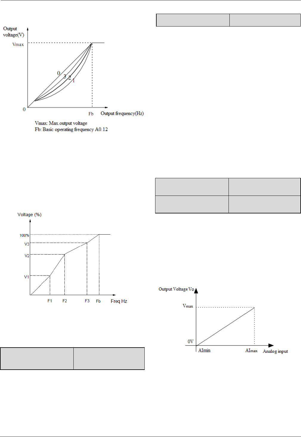
56
56
according to the actual load so as to achieve best
energy-saving effects.
Fig.6-35 Torque-reducing curve
If b1.00 is set to 0, you can define V/F curve via
b1.01~b1.06, as shown in Fig. 6-36. The V/F curve can
be defined by connecting 3 points of (V1,F1), (V2,F2)
and (V3, F3), to adapt to special load characteristics.
Default V/F curve set by factory is a direct line as show
in Fig. 6-35 as curve 0.
Fig.6-36V/F curve defined by user
b1.07 Cut-off point used
for manual torque boost 0.0%~50.0%【10.0%】
b1.07 defines the ratio of the cut-off frequency used for
manual torque boost to the basic operating frequency
(defined by A0.12), as shown in Fig. 6-36 as Fz.This
cut-off frequency adapts to any V/F curve defined by
b1.00.
b1.08 AVR function 0~2【1】
0: Disable
1: Enable all the time
2: Disabled in Dec process
AVR means automatic voltage regulation.
The function can regulate the output voltage and make it
constant. Therefore, generally AVR function should be
enabled, especially when the input voltage is higher than
the rated voltage.
In Dec-to-stop process, if AVR function is disabled, the
Dec time is short but the operating current is big. If AVR
function is enabled all the time, the motor decelerates
steadily, the operating current is small but the Dec time
is prolonged.
b1.09 VF Output Voltage
Selection 0~3
b1.10 VF Output Voltage
Offset Selection 0~3
Example 1:The output voltage in V/F mode is controlled
by AI.
Set a value (not zero) to b1.09 to select an analog input
to control voltage output.This function is only valid in
V/F control mode.The output frequency and output
voltage VO is completely independent of each other.The
output voltage is controlled by analog input signal,not by
the V/F curve in Group b1,as shown in Fig.6-37.
Fig.6-37 Curve of Output voltage
Example 2:The offset of output voltage in V/F mode is
controlled by AI.
Set a value (not zero) to b1.10 to select an analog input
to control the offset of voltage output.As shown in
Fig.6-38.
V1~V3: Voltage of sections 1~3
F1~F3: Freq of sections 1~3
Fb:Basic operating frequency of A0.12
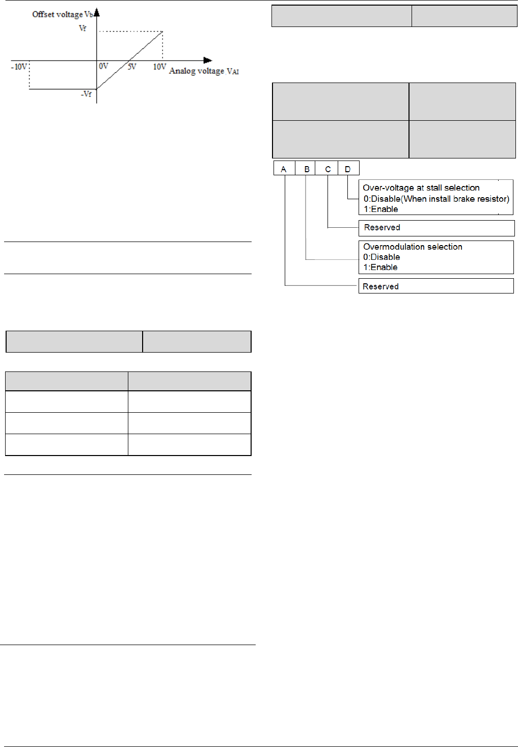
57
57
Fig.6-38 Offset of output voltage
The output voltage corresponding to the setting
frequency in the V/F curve is V/F, then the relationship
between analog input and offset voltage is as follows:
If analog input VAI is -10V~0V or 4mA, then the
corresponding offset voltage is –V or F. If analog input
VAI is 10V or 20mA, then the corresponding offset
voltage is V or F.
The output voltage is VO=V/F+Vb
Note
AI offset is only valid in V/F control mode.
6.12 Group b2
b2.00 Carrier wave frequency 2.0~15.0kHz【6kHz】
Drive’s type and carrier wave frequency (CWF)
Drives power Default CWF value
2.2~5.5 kW 10kHz
7.5~55 kW 6kHz
55~250 kW 2kHz
Note:
1. The carrier wave frequency will affect the noise when
motor running, generally the carrier wave frequency is
supposed to set as 3~5kHz. For some special situation
where require operating mutely, the carrier wave
frequency is supposed to set as 6~8kHz.
2.When set the carrier wave frequency larger than
default value, then the power of drive need to derate 5%
by every increase of 1kHz.
b2.01Auto adjusting of CWF 0~1【1】
0: Disable
1: Enable
b2.02 Voltage adjustment
selection 000~111H【001H】
b2.03 Overvoltage point at
stall 120~150%【140.0%】
During deceleration, the motor’s decelerate rate may be
lower than that of drive’s output frequency due to the
load inertia. At this time, the motor will feed the energy
back to the drive, resulting in the voltage rise on the
drive's DC bus. If no measures taken, the drive will trip
due to over voltage.
During the deceleration, the drive detects the bus voltage
and compares it with the over voltage point at stall
defined by b2.03. If the bus voltage exceeds the stall
overvoltage point, the drive will stop reducing its output
frequency. When the bus voltage becomes lower than the
point, the deceleration continues. As shown in Fig.6-39.
The hundred’s place is used to set overmodulation
function of V/F control. For vector control, the
overmodulation function will be always enable.
Overmodulation means when the voltage of power grid
is low for long term (Lower than 15% of rated voltage),
or is overload working for long term, then the drives will
increase the use ratio of its own bus voltage to increase
output voltage.
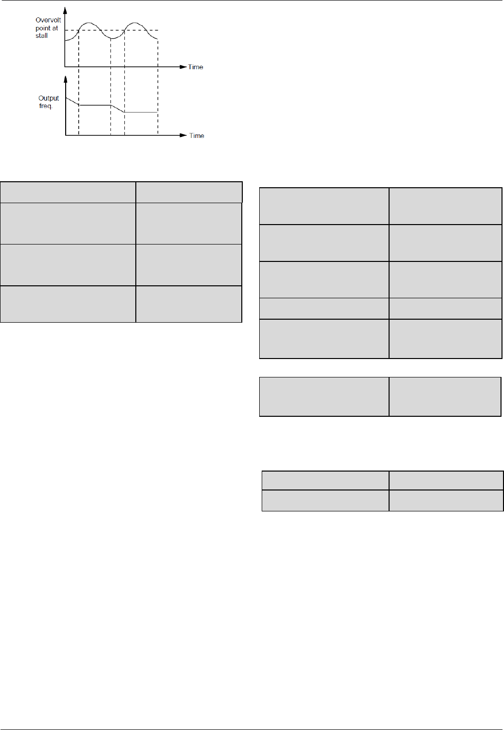
58
58
Fig.6-39 Over-voltage at stall
b2.04: Droop control 0.00~10.00Hz【0.00Hz】
b2.05 Auto current limiting
threshold
20.0~200.0%
【150.0%】
b
2.06 Frequency decrease rate
when current limiting
0.00~99.99Hz/s
【1.00Hz/s】
b2.07 Auto current limiting
selection 0~1【1】
Droop control is used to distribute the load automatically
by adjusting the output frequency when several VFDs
drive the same load.
Auto current limiting function is used to limit the load
current smaller than the value defined by b2.05 in real
time. Therefore the drive will not trip due to surge
over-current. This function is especially useful for the
applications with big load inertia or big change of load.
b2.05 defines the threshold of auto current limiting. It is
a percentage of the drive’s rated current.
b2.06 defines the decrease rate of output frequency when
the drive is in auto current limiting status.
If b2.06 is set too small, overload fault may occur. If it is
set too big, the frequency will change too sharply and
therefore, the drive may be in generating status for long
time, which may result in overvoltage protection.
Auto current limiting function is always active in Acc or
Dec process. Whether the function is active in constant
speed operating process is decided by b2.07.
b2.07=0, Auto current limiting function is disabled in
constant speed operating process;
b2.07=1, Auto current limiting function is enabled in
constant speed operating process;
In auto current limiting process, the drive’s output
frequency may change; therefore, it is recommended not
to enable the function when the drive’s output frequency
is required stable.
When the auto current limiting function is enabled, if
b2.05 is set too low, the output overload capacity will be
impaired.
b2.08 Gain of slip
compensation 0.0~300.0%【100%】
b2.09 Limit of slip
compensation 0.0~250.0%【200%】
b2.10 Slip compensation
time constant 0.1~25.0s【2】
b2.11 Energy-saving function 0:Disable. 1:Enable. 【0】
b2.12 Frequency decrease
rate at voltage compensation
0.00~99.99Hz
【10.00 Hz/s】
b2.13Threshold of
zero-frequency operation
0.00~300.00Hz
【0.50 Hz/s】
This parameter is used together with No.9 function of
digital output terminal.
b2.14 Reserved
b2.15 Fan control 0~1【0】
0: Auto operating mode.
The fan runs all the time when the drive is operating.
After the drive stops, its internal temperature detecting
program will be activated to stop the fan or let the fan
continue to run according to the IGBT’s temperature.
The drive will activate the internal temperature detecting
program automatically when it is operating,and run or
stop the fan according to the IGBT’s temperature.If the
fan is still running before the drive stop,then the fan will
continue running for three minutes after the drive stops
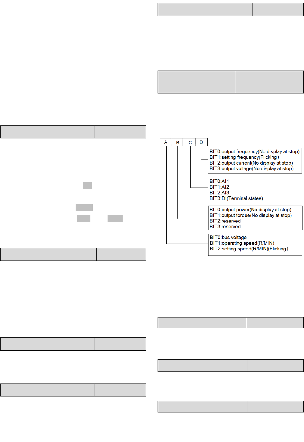
59
59
and then activate the internal temperature detecting
program.
1: The fan operates continuously when the power is on.
6.13 Group b3
Details please refer to the Group b3 of function list in
chapter 9.
6.14 Group b4
b4.00 Key-lock function selection 0~4【0】
0: The keys on the operation panel are not locked, and
all the keys are usable.
1: The keys on the operation panel are locked, and all the
keys are unusable.
2: All the keys except for the M (Multi-function)key
are unusable.
3: All the keys except for the SHIFT key are unusable.
4: All the keys except for the RUN AND STOP keys are
unusable.
b4.01 Multi-functional key function 0~5【4】
0: Jog
1: Coast to stop
2: Quick stop
3: Operating commands switchover
4: Switch forward/reverse.(Save after power failure)
5: Switch forward/reverse.(Not save after power failure)
b4.02 Parameter protection 0~2【0】
0: All parameters are allowed modifying;
1: Only A0.03 and b4.02 can be modified;
2: Only b4.02 can be modified.
b4.03 Parameter initialization 0~2【0】
0: Parameter adjustable
1: Clear fault information in memory
2: Restore to factory settings
b4.04 Parameter copy 0~3【0】
0: No action
1: parameters upload
2: parameters download
3: parameters download (except the parameters related
to drive type)
b4.05 Display parameters
selection 0~7FFFH【1007H】
b4.05 define the parameters that can be displayed by
LED in operating status.
If Bit is 0, the parameter will not be displayed;
If Bit is 1, the parameter will be displayed.
Note:
If all the BITs are 0, the drive will display setting
frequency at stop and display output frequency at
operating
b4.06 Line speed coefficient 0.00~99.99
It is used to multiply the operating frequency and the
ratio as the final value to display in the panel.
Displayed value=operating frequency*b4.06
b4.07 Rotary speed coefficient 0.000~30.000
It is used to calculate the display value of rotary speed in
LED.
Display value=Operating speed*b4.07
b4.08~b4.15 Reserved Reserved
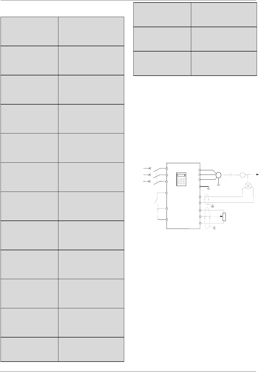
60
60
6.15 Group C0
C0.00 Preset frequency 1
Lower limit of frequency~
upper limit of frequency
【5.00Hz】
C0.01 Preset frequency 2
Lower limit of frequency~
upper limit of frequency
【10.00Hz】
C0.02 Preset frequency 3
Lower limit of frequency~
upper limit of frequency
【15.00Hz】
C0.03 Preset frequency 4
Lower limit of frequency~
upper limit of frequency
【20.00Hz】
C0.04 Preset frequency 5
Lower limit of frequency~
upper limit of frequency
【25.00Hz】
C0.05 Preset frequency 6
Lower limit of frequency~
upper limit of frequency
【30.00Hz】
C0.06 Preset frequency 7
Lower limit of frequency~
upper limit of frequency
【35.00Hz】
C0.07 Preset frequency 8
Lower limit of frequency~
upper limit of frequency
【40.00Hz】
C0.08 Preset frequency 9
Lower limit of frequency~
upper limit of frequency
【45.00Hz】
C0.09 Preset frequency
10
Lower limit of frequency~
upper limit of frequency
【50.00Hz】
C0.10 Preset frequency
11
Lower limit of frequency~
upper limit of frequency
【10.00Hz】
C0.11 Preset frequency
12
Lower limit of frequency~
upper limit of frequency
【20.00Hz】
C0.12 Preset frequency
13
Lower limit of frequency~
upper limit of frequency
【30.00Hz】
C0.13 Preset frequency
14
Lower limit of frequency~
upper limit of frequency
【40.00Hz】
C0.14 Preset frequency
15
Lower limit of frequency~
upper limit of frequency
【50.00Hz】
These frequencies will be used in multi-step speed
operation, refer to the introductions of No.27,28,29 and
30 function of A6.00~A6.07.
6.16 Group C1
Process close-loop control
The process closed-loop control type of FV100 is analog
close-loop control. Fig.6-40 shows the typical wiring of
analog close-loop control.
Fig.6-40 Analog feedback control system with
internal process close-loop
Analog feedback control system:
An analog feedback control system uses a pressure
transmitter as the feedback sensor of the internal
close-loop.
As shown in Fig. 6-40, pressure reference (voltage
signal) is input via terminal AI2, while the feedback
pressure value is input into terminal AI1 in the form of
4~20mA current signal. The reference signal and
feedback signal are detected by the analog channel.The
start and stop of the drive can be controlled by terminal
Xi.
The above system can also use a TG (speed measuring
generator) in close speed-loop control.
FV100
U
M
QF
+10V
+10V
AI1
Xi
COM
P
AC
input
Pressure
transmitter
Out
p
ut
V
W
PE
-10V
AI2
R
S
T
GND
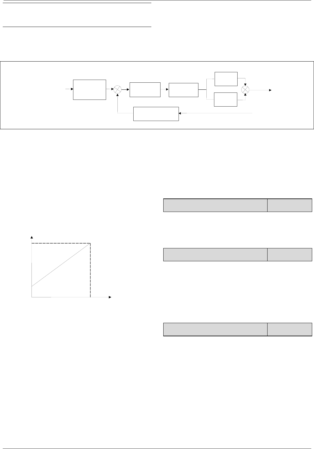
61
61
Note:
The reference can also be input via panel or serial port.
Operating principles of internal process close-loop of
FV100 is shown in the Fig. 6-41
In the Fig。, KP: proportional gain; Ki: integral gain
In Fig. 6-41, refer to C1.00~C1.14 for the definitions of
close-loop reference, feedback, error limit and
proportional and Integral parameters.
Fig.6-41 Principle diagram of process close-loop control
There are two features of internal close-loop of FV100:
The relationship between reference and feedback can be
defined by C1.05~C1.08
For example: In Fig.6-40, if the reference is analog
signal of -10~10V, the controlled value is 0~1MP, and
the signal of pressure sensor is 4~20mA, then the
relationship between reference and feedback is shown
in Fig. 6-42.
Fig.6-42 Reference and feedback
After the control type is determined, follow the
procedures below to set close loop parameters.
1) Determine the close-loop reference and feedback
channel (C1.01 and C1.02);
2) The relationship between close-loop reference and
feedback value (C1.05~C1.08) should be defined for
analog close-loop control;
3) Determine the close-loop regulation characteristic, if
the relationship between motor speed and the reference
is opposite,then set the close-loop regulation
characteristic as negative characteristic(C1.15=1).
4) Set up the integral regulation function and close-loop
frequency presetting function (C1.16~C1.18);
5) Adjust the close-loop filtering time, sampling cycle,
error limit and gain(C1.09~C1.14).
C1.00 Close-loop control function 0、1【0】
0:Disable.
1:Enable.
C1.01 Reference channel selection 0~3【1】
0: digital input
Take the value of C1.03 .
1: AI1 analog input.
2: AI2 analog input
3:AI3 analog voltage input.
C1.02 Feedback channel selection 0~5【1】
0: AI1 analog input
1: AI2 analog input
2: AI1+ AI2
3: AI1-AI2
4: Min{ AI1,AI2}
5: Max{ AI1,AI2}
6: Pulse DI
Settings of AI are the same as above.
10V- 10V Referenc
4mA
20mA
Feedbac
Reference
Reference
regulation
(C1.05、 C 1 . 0 7
)
εError limit
(C1.14 )
+
-
Feedback
KP×
(C1.09)
Ki×
(C1.10)
Regulation
(C1.15)
ε
ε
∑
+
+
Output
Feedback regulation
(C1.06、C1.08)
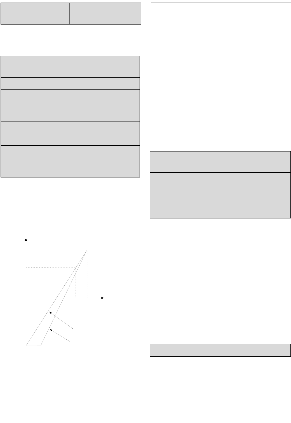
62
62
C1.03 Digital setting of
reference
-10.00~10.00V【0.00】
This function can realize digital setting of reference via
panel or serial port.
C1.04 Close-loop speed
reference 0~39000rpm
C1.05 Min reference 0.0%~C1.08【0.0%】
C1.06 Feedback value
corresponding to the Min
reference
0.0~100.0%【0.0%】
C1.07 Max reference
C1.06~100.0%
【100.0%】
C1.08 Feedback value
corresponding to the Max
reference
0.0~100.0%【100.0%】
The regulation relationship between C1.05,C1.07(in
Fig.6-41) and reference is shown in Fig.6-43.When the
analog input 6V,if C1.05=0% and C1.07=100%,then
adjusted value is 60%.If C1.05=25% and C1.07=
100%,then the adjusted value is 46.6%.
Fig.6-43 Regulation curve of reference
Note:
1.Fig.6-43,0%~100% in X axis is corresponding to
analog input -10V ~10V,10V of analog input is
corresponding to 100%,and-10V is corresponding to
0%,6V is corresponding to 80%.
2.If the analog type is current input,because of the
currentinput range is 4~20mA,then the range of X axis
is 50%~100%.
3.The adjusted value can be observed in d0.24.
The regulation relationship between C1.06, C1.08(in
Fig.6-41) and feedback is similar to reference
regulation.Its adjusted value can be observed in d0.25.
C1.09 Proportional gain
KP 0.000~10.000【2.000】
C1.10 Integral gain Ki 0.000~10.000【0.100】
C1.11 Differential gain
Kd 0.000~10.000【0.100】
C1.12 Sampling cycle T 0.01~50.00s【0.50s】
The bigger the proportional gain of KP, the faster the
response, but oscillation may easily occur.
If only proportional gain KP is used in regulation, the
error cannot be eliminated completely. To eliminate the
error, please use the integral gain Ki to form a PI control
system. The bigger the Ki, the faster the response, but
oscillation may easily occur if Ki is too big.
The sampling cycle T refers to the sampling cycle of
feedback value. The PI regulator calculates once in each
sampling cycle. The bigger the sampling cycle the
slower the response.
C1.13 Output filter 0.01~10.00【0.05】
This parameter defines the filter time of the close-loop
output (Frequency or torque).The bigger the output
filter,the slower the response.
- 10 0%
10 0 %
Analog input
Adjusted value
0 %100 %
5 0%
2 5%
C1.05= 2 5%
C1 .07 = 10 0%
C1.05 = 0%
C1
.07= 1 00 %
80%
( 6V)
6 0 %
46 . 6 %
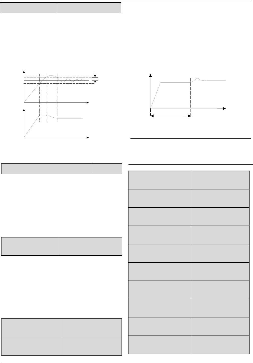
63
63
C1.14 Error limit 0.0~20%【2.0%】
This parameter defines the max. deviation of the output
from the reference, as shown in Fig. 6-44. Close-loop
regulator stops operation when the feedback value is
within this range.Setting this parameter correctly is
helpful to improve the system output accuracy and
stability.
Fig.6-44 Error limit
C1.15 Close-loop regulation characteristic 0、1【0】
0: Positive
Set C1.15 to 0 if the motor speed is required to be
increased with the increase of the reference.
1: Negative
Set C1.15 to 1 if the motor speed is required to decrease
with the increase of the reference.
C1.16 Integral regulation
selection 0、1【0】
0: Stop integral regulation when the frequency reaches
the upper and lower limits
1: Continue the integral regulation when the frequency
reaches the upper and lower limits
It is recommended to disable the integral regulation for
the system that requires fast response.
C1.17 Preset close-loop
frequency 0.00~1000.0Hz【0.00Hz】
C1.18 Holding time of
Preset close-loop frequency 0.0~3600.0s【0.0s】
This function can make the close-loop regulation enter
stable status quickly.
When the close-loop function is enabled, the frequency
will ramp up to the preset close-loop frequency (C1.17)
within the Acc time, and then the drive will start
close-loop operation after operating at the preset
frequency for certain time(defined by C1.18).
Fig.6-45 Preset frequency of close-loop operation
Note:
You can disable the function by set both C1.17 and
C1.18 to 0.
C1.19 Preset close-loop
reference 1
-10.00~10.00V【0.00V】
C1.20 Preset close-loop
reference 2
-10.00~10.00V【0.00V】
C1.21 Preset close-loop
reference 3
-10.00~10.00V【0.00V】
C1.22 Preset close-loop
reference 4
-10.00~10.00V【0.00V】
C1.23 Preset close-loop
reference 5
-10.00~10.00V【0.00V】
C1.24 Preset close-loop
reference 6
-10.00~10.00V【0.00V】
C1.25 Preset close-loop
reference 7
-10.00~10.00V【0.00V】
C1.26 Preset close-loop
reference 8
-10.00~10.00V【0.00V】
C1.27 Preset close-loop
reference 9
-10.00~10.00V【0.00V】
C1.28 Preset close-loop
reference 10
-10.00~10.00V【0.00V】
Error limit
Feedback value
Output
frequency
Time
Time
Holding time of
Preset frequency
Output frequency
Preset frequency
T(time)
Reference
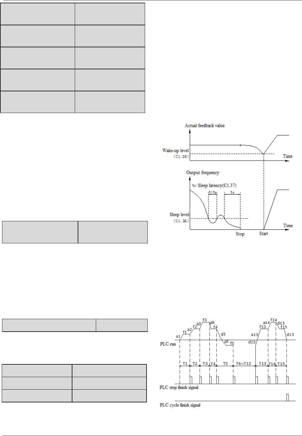
64
64
C1.29 Preset close-loop
reference 11
-10.00~10.00V【0.00V】
C1.30 Preset close-loop
reference 12
-10.00~10.00V【0.00V】
C1.31 Preset close-loop
reference 13
-10.00~10.00V【0.00V】
C1.32 Preset close-loop
reference 14
-10.00~10.00V【0.00V】
C1.33 Preset close-loop
reference 15
-10.00~10.00V【0.00V】
Among the close-loop reference selectors, besides the 3
selectors defined by C1.01, the voltage value defined by
C1.19~C1.33 can also be used as the close-loop
reference.
Voltage of preset close-loop reference 1~15 can be
selected by terminals, refer to introductions to
A6.00~A6.06 for details.
The priority preset close-loop reference control is higher
than the reference selectors defined by C1.01
C1.34 Close-loop output
reversal selection 0、1【0】
0: The close-loop output is negative,the drive will
operate at zero frequency.
1: The close-loop output is negative,and the drive
operate reverse.If the anti-reverse function is
activated,then the drive will operate at zero
frequency.Refer to the instructions of A1.12.
C1.35 Sleep function selection 0,1【0】
0:Disable
1:Enable.
C1.36 Sleep level 0.0~100.0%【50.0%】
C1.37 Sleep latency 0.0~600.0s【30.0s】
C1.38 Wake-up level 0.0~100%【50.0%】
As shown in Fig.6-46,when the output frequency is
lower than the sleep level(C1.36),timer for sleep latency
will start.When the output frequency is larger than the
sleep level,the timer for sleep latency will stop and
clear.If the time of the situation that the output frequency
is lower than the sleep level is longer than sleep
latency(C1.37),then the driver will stop.When the actual
feedback value is higher than wake-up level(C1.38),the
driver will start again.
In Sleep level (C1.36), 100% is corresponding to the
frequency in A0.08.
In Wake-up level (C1.38), 100% is corresponding to
10V or 20mA.
Fig.6-46 Sleep Function
6.17 Group C2
Simple PLC function
Simple PLC function is used to run different frequency
and direction in different time automatically,as shown in
Fig.6-46
Fig.6-46 Simple PLC function
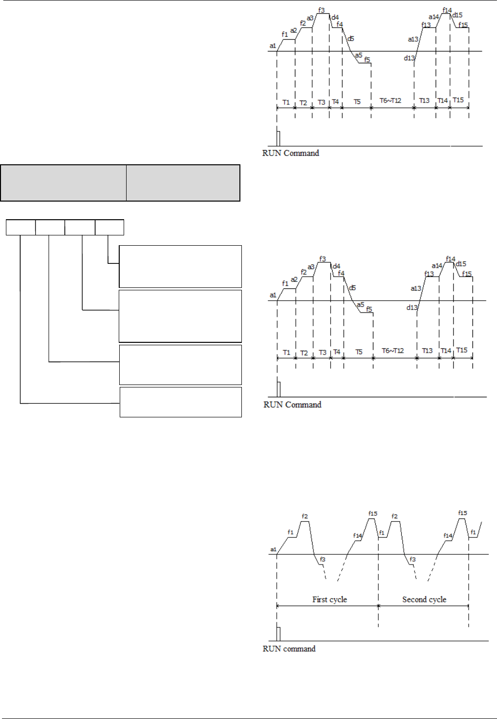
65
65
In Fig.6-46, a1~a15 and d1~d15 are the acceleration and
deceleration of the steps.f1~f15 and T1~T15 are the
setting frequency and operating time of the steps.There
parameters are defined in group C2.
PLC step finish signal and PLC cycle finish signal can
be output with pulse signal which last 500ms by
bi-direction open collector output Y1, open collector
output Y2 or relay. Set function code as 12 and 13 for
parameters A6.14, A6.16 or A6.25.
C2.00 Simple PLC operation
mode selector 0~1123H【0000】
The unit’s place of LED: PLC function running mode
0: No function.
Simple PLC function is invalid.
1: Stop after single cycle.
As shown in Fig.6-47, the drive will stop automatically
after finishing one cycle running,the wait for another
start signal to startup.
Fig.6-47 Stop after single cycle
2. Keep final states after single cycle
As shown in Fig.6-48, the drive will keep running at the
frequency and direction in last step after finishing single
cycle.
Fig.6-48 Keep final states after single cycle
3. Continuous cycle
As shown in Fig.6-49, the drive will continue next cycle
after finishing one cycle, and stop when there is stop
command.
Fig.6-49 Continuous cycle
A BCD
0:
N
o function
1: Stop after single cycle
2: Keep final states after single cycle
3: Continuous cycle
0: Start from first step
1: Start from the step before stop
(or alarm).
2:
before stop(or alarm)
Start from the step and frequency
Storage after power of
f
0: Disable
1: Save the segment,frequency when
p
ower of
f
Time unit selector for each step
0: Second
1: Minute
Start mode
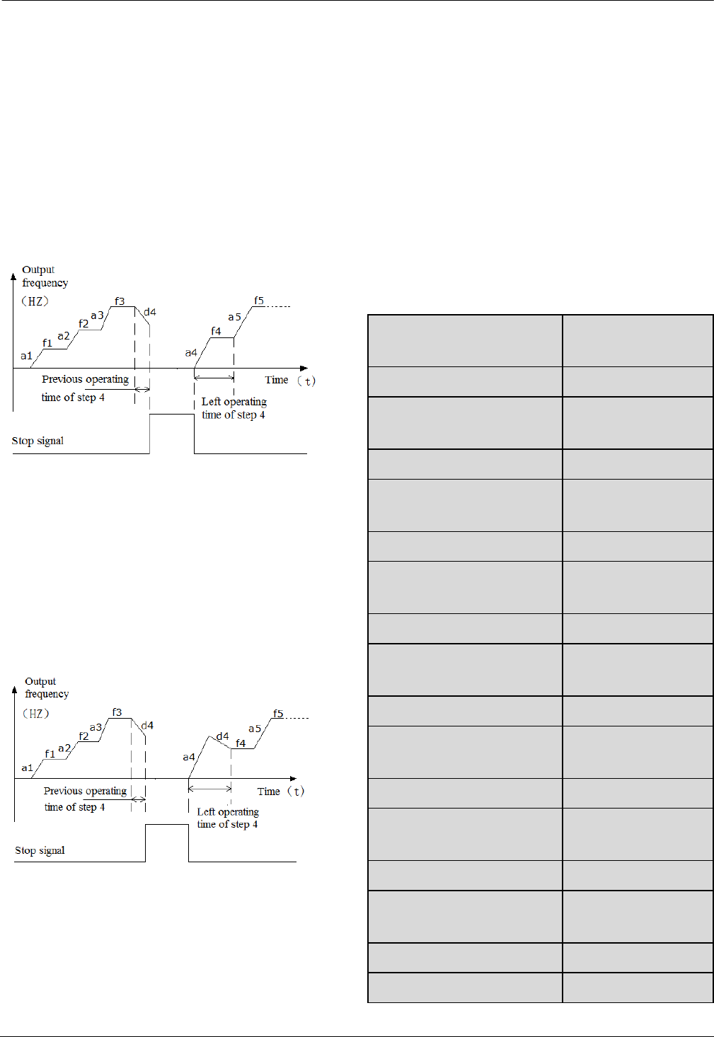
66
66
The ten’s place of LED: Start modes
0: Start from first step
If the drive stop while it was running (Caused by stop
command, fault or power failure), then it will start from
first step when it restart.
1: Start from the step before stop (or alarm)
If the drive stop while it was running(Caused by stop
command or fault), then it will record the operating time
of current step,and start from this step and continue the
left operating time when it restart,as shown in Fig.6-50.
Fig.6-50 Start mode 1 of PLC function
2. Start from the step, frequency before stop(or alarm)
If the drive stop while it was running(Caused by stop
command or fault),it will record the operating time of
current step and also record the operating frequency,then
when it restart,it will return to the operating frequency
before stop and continue the left operating time,as
shown in Fig.6-51.
Fig.6-51 Start mode 2 of PLC function
Hundred’s place of LED: Save after power off
0: Not save
The drive will not save the PLC operating status after
power off.It will start from first step after power on
again.
1: Save the segment frequency after power off
It will save the PLC operating status including
step,operating frequency and operating time,then it will
restart according the the setting in ten’s place of LED
when power on again.
Thousand’s place of LED: Time unit selector of each
step
0: Second
Each steps will use second as the unit of operating time.
1: Minute
Each steps will use minute as the unit of operating time.
This unit selector is only valid for PLC operating time.
C2.01 Step 1 setting mode
selector 0~323H【0000】
C2.02 Step 1 operating time 0.0~6500.0【20.0】
C2.03 Step 2 setting mode
selector 0~323H【0000】
C2.04 Step 2 operating time 0.0~6500.0【20.0】
C2.05 Step 3 setting mode
selector 0~323H【0000】
C2.06 Step 3 operating time 0.0~6500.0【20.0】
C2.07 Step 4 setting mode
selector 0~323H【0000】
C2.08 Step 4 operating time 0.0~6500.0【20.0】
C2.09 Step 5 setting mode
selector 0~323H【0000】
C2.10 Step 5 operating time 0.0~6500.0【20.0】
C2.11 Step 6 setting mode
selector 0~323H【0000】
C2.12 Step 6 operating time 0.0~6500.0【20.0】
C2.13 Step 7 setting mode
selector 0~323H【0000】
C2.14 Step 7 operating time 0.0~6500.0【20.0】
C2.15 Step 8 setting mode
selector 0~323H【0000】
C2.16 Step 8 operating time 0.0~6500.0【20.0】
C2.17 Step 9 setting mode 0~323H【0000】
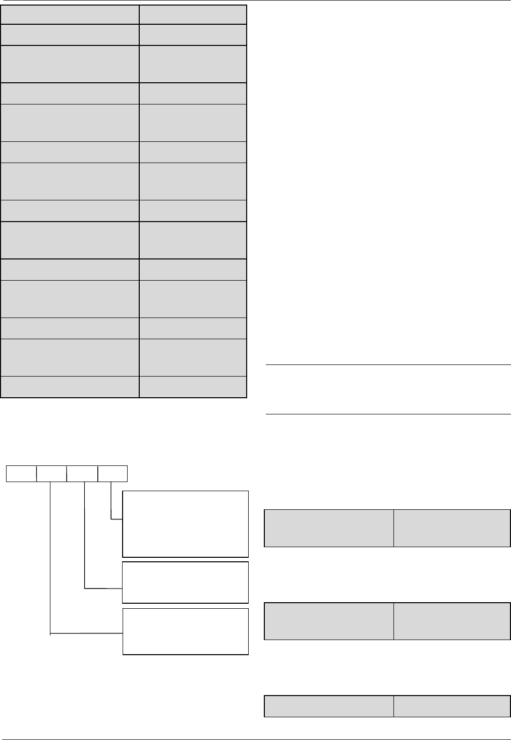
67
67
selector
C2.18 Step 9 operating time 0.0~6500.0【20.0】
C2.19 Step 10 setting mode
selector 0~323H【0000】
C2.20 Step 10 operating time 0.0~6500.0【20.0】
C2.21 Step 11 setting mode
selector 0~323H【0000】
C2.22 Step 11 operating time 0.0~6500.0【20.0】
C2.23 Step 12 setting mode
selector 0~323H【0000】
C2.24 Step 12 operating time 0.0~6500.0【20.0】
C2.25 Step 13 setting mode
selector 0~323H【0000】
C2.26 Step 13 operating time 0.0~6500.0【20.0】
C2.27 Step 14 setting mode
selector 0~323H【0000】
C2.28 Step 14 operating time 0.0~6500.0【20.0】
C2.29 Step 15 setting mode
selector 0~323H【0000】
C2.30 Step 15 operating time 0.0~6500.0【20.0】
C2.01~C2.30 are used to set the operating frequency,
direction, Acc/Dec time and operating time for PLC
function.Here takes C2.01 as example,as shown in
Fig.6-52.
Fig.6-52 PLC steps setting
The unit’s place of LED:
0: Multiple frequency N(N:corresponding to current
step)The frequency of current step depends on the
multiple frequency N.About the details of multiple
frequency setting,please refer to Group C0.
1: Defined by A0.02.
Use A0.02 to set the frequency of current step.
2: Multiple closed loop reference N(N:corresponding to
current step)The frequency of current step depends on
the multiple closed loop reference N.About multiple
closed loop setting,please refer to C1.19~C1.33.
3: Defined by C1.01.
PLC runs in process closed loop mode,the closed loop
reference is defined by C1.01.
Ten’s place of LED:
0: Forward
Set the direction of current step as forward
1: Reverse
Set the direction of current step as reverse
2: Defined by operation command
The direction of current step is defined by the operation
command of terminals.
Note:
If the operation direction of current step can not be
confirmed,then it will continue the previous direction.
6.18 Group d0
The parameters of Group d0 are used to monitor some
states of drives and motors.
d0.00 Main reference
frequency
-300.0~300.0Hz【0.00】
This parameter is used to monitor main reference
frequency at normal operation mode.
d0.01 Auxiliary reference
frequency
-300.0~300.0Hz【0.00】
This parameter is used to monitor the auxiliary reference
frequency at normal operation mode.
d0.02 Preset frequency -300.0~300.0Hz【0.00】
A BCD
0: Multiple frequency N(N:
1:
corresponding to current step)
2: Multiple closed-loop reference N
3:
Defined by A0.02cycle
0: Forward
1: Reverse
2: Defined by operation comman
d
0: Acc/Dec time 1
(N:corresponding to current step)
Defined by C1.01
Acc/Dec time 2
1:
Acc/Dec time 3
2:
Acc/Dec time 4
3:
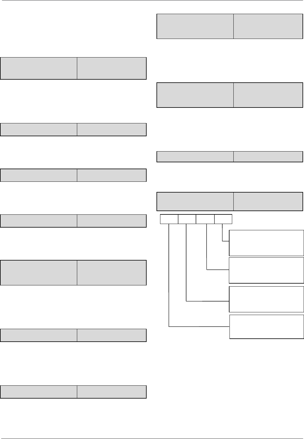
68
68
This parameter is used to monitor the frequency
combined by main reference frequency and auxiliary
reference frequency.Positive indicates running forwards,
negative indicates running reverse.
d0.03 Frequency after
Acc/Dec
-300.0~300.0Hz【0.00】
This parameter is used to monitor the drive’s output
frequency (include direction) after the drive accelerating
or decelerating.
d0.04 Output frequency -300.0~300.0Hz【0.00】
This parameter is used to monitor the drive’s output
frequency (include direction).
d0.05 Output voltage 0~480V【0】
This parameter is used to monitor the drive’s output
voltage.
d0.06 Output current 0.0~3Ie【0】
This parameter is used to monitor the drive’s output
current.
d0.07 Torque current
-300.0%~300.0%
【0.0%】
This parameter is used to monitor the percentage of
drive’s torque current that corresponding to the motor’s
rated current.
d0.08 Magnetic flux current 0.0%~100.0%【0.0】
This parameter is used to monitor the percentage of
drive’s magnetic flux current that corresponding to the
motor’s rated current.
d0.09 Motor power 0.0%~200.0%【0.0】
This parameter is used to monitor the percentage of
drive’s output power that corresponding to the motor’s
rated power.
d0.10 Motor estimated
frequency
-300.00~300.00Hz
【0.00】
This parameters is used to monitor the estimated motor
rotor frequency under the condition of open-loop vector
control.
d0.11 Motor actual
frequency
-300.00~300.00Hz
【0.00】
This parameter is used to monitor the actual motor rotor
frequency measured by encoder under the condition of
close-loop vector control.
d0.12 Bus voltage 0~800V【0】
This parameter is used to monitor the drive’s bus
voltage.
d0.13 Drive operation
status 0000~FFFFH【0000】
Fig.6-47 The drive’s operation status
A BCD
BIT0
: 0:Stop. 1:Run
BIT1
: 0:Forward. 1:Reverse
BIT2
:Operating at zero frequecy
BIT3
:Accelerating
BIT0
:Decelerating
BIT1
:Operating at constant speed
BIT2
:Pre-commutation
BIT3
:Tuning
BIT0
:Over-current limiting
BIT1
:DC over-voltage limiting
BIT2
:Torque limiting
BIT 3 Reversed
BIT0
:Drive fault
BIT1
:Speed control
BIT2
:Reserved
BIT 3
:Reserved
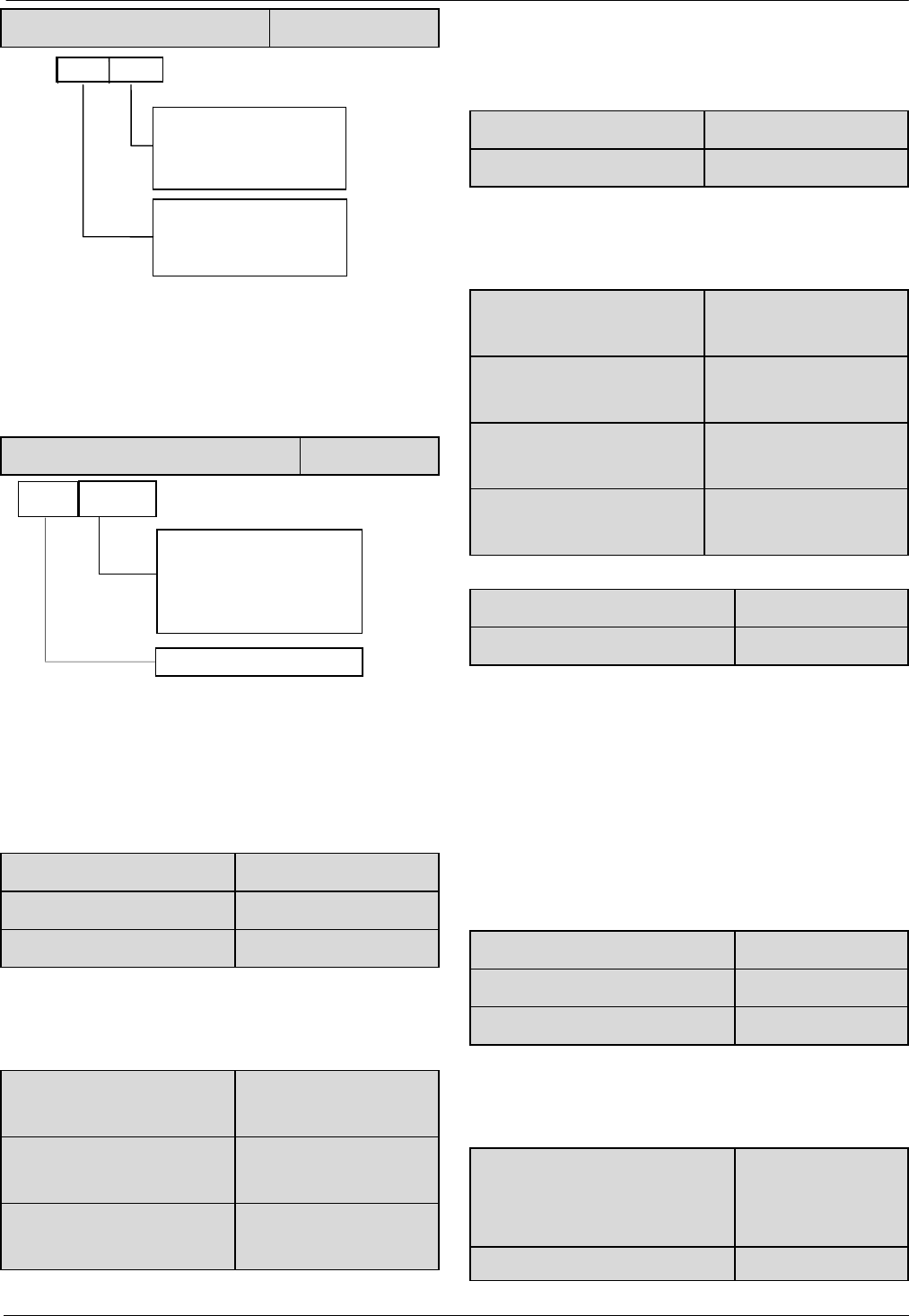
69
69
d0.14 Input terminals status 00~FFH【00】
Fig.6-48 Input terminals status
This parameter is used to display the status of X1~X7.
0 indicates OFF status,1 indicates ON status.
d0.15 Output terminals status 0~1FH【0】
Fig.6-49 Output terminal status
This parameter is used to display the status of output
terminals.When there is signal output,the corresponding
bit will be set as 1.
d0.16 AI1 input -10.00~10.00V【0.00】
d0.17 AI2 input -10.00~10.00V【0.00】
d0.18 AI3 input -10.00~10.00V【0.00】
d0.16~d0.18 are used to display the analog input value
before regulation.
d0.19 Percentage of AI1 after
regulation -100.0%~100.0%【0.0】
d0.20 Percentage of AI2 after
regulation -100.0%~100.0%【0.0】
d0.21 Percentage of AI3 after
regulation -100.0%~100.0%【0.0】
d0.19~d0.21 are used to display the percentage of
analog input after regulation.
d0.22 AO1 output 0.0%~100.0%【0.0】
d0.23 AO2 output 0.0%~100.0%【0.0】
d0.22、d0.23 are used to display the percentage of analog
output that corresponding to the full range.
d0.24 Process close-loop
reference -100.0%~100.0%【0.0】
d0.25 Process close-loop
feedback -100.0%~100.0%【0.0】
d0.26 Process close-loop
error -100.0%~100.0%【0.0】
d0.27 Process close-loop
output -100.0%~100.0%【0.0】
d0.28 Temperature of heatsink 1 0.0~150.0℃【0.0】
d0.29 Temperature of heatsink 2 0.0~150.0℃【0.0】
Temperature of heatsink 1 is the temperature of IGBT
modules. Different IGBT modules have different
over-temperature threshold.
Temperature of heatsink 2 is the temperature of rectifier.
The drive of 30kW or below does not detect this
temperature.
Temperature display range:0~100℃.Accuracy: 5%
d0.30 Total conduction time 0~65535 hours【0】
d0.31 Total operating time 0~65535 hours【0】
d0.32 Total fan’s operating time 0~65535 hours【0】
d0.30~d0.32 define the drive’s total conduction time,
operating time and fan’s operating time after production.
d0.33 ASR controller output -300.0~300.0%
(Corresponding to
rated torque of motor
d0.34 Reference torque -300.0~300.0%
D
BIT0
:
Y1 terminal status
BIT1
:Reserved
BIT2
:
R01 relay status
BIT3
:
Reserved
BIT4:Y2 terminal status
CD
BIT0:
X1terminal status
BIT1:
X2terminal status
BIT2:
X3terminal status
BIT3
:
X4terminal status
BIT0:
X5terminal status
BIT1:
X6terminal status
BIT2:
X7terminal status
BIT3
:
Reserved
C D
BIT1: Y2 terminal status

70
70
(Corresponding to
rated torque of motor
d0.35 Zero offset of AI1 0~65535
d0.36 Zero offset of AI2 0~65535
d0.37 Zero offset of AI3 0~65535
d0.38~d0.45 Reserved Reserved
d0.35~d0.45 is read only.
6.19 Group d1
d1.00 Fault record 1 0~50【0】
d1.01 Bus voltage of the latest
failure 0~999V【0】
d1.02 Actual current of the latest
failure 0.0~999.9A【0】
d1.03 Operation frequency of the
latest failure 0.00~300.0Hz【0.00】
d1.04 Operation status of the
latest failure 0~FFFFH【0000】
d1.05 Fault record 2 0~50【0】
d1.06 Fault record 3 0~50【0】
FV100 support 50 kinds of protection alarm and can
record the latest three fault code (d1.00,d1.05,d1.06) and
bus voltage, current, operation frequency and operation
status of the latest fault.
Fault record 1 is the latest fault record.
See Chapter 7 of failure and alarm information during
failures recently occurred for the ease of Trouble
Shooting and repair.
6.20 Group d2
d2.00 Serial number 0~FFFF【100】
d2.01 Software version 0.00~99.99【1.00】
number
d2.02 Custom-made version
number 0~9999【0】
This group of parameters can’t be changed by user.
d2.03 Load type selection 0~9【0】
0: Heavy load G.
1: Light load L, such as fan.
2: Serging type B, such as lift.
3: 2-phase output type S.
4~9: Reserved.
d2.04 Rated capacity
Output power
0~999.9KVA
(Factory setting)
d2.05 Rated voltage 0~999V
(Factory setting)
d2.06 Rated current 0~999.9A
(Factory setting)

71
71
Chapter 7 Troubleshooting
Table 7-1 list the possible faults of FV100, the fault code varies from E001 to E050. Once a fault occurs, you may
check it against the table and record the detailed phenomena before seeking service from your supplier.
Table 7-1 Faults and actions
Fault code Fault categories Possible reasons for fault Actions
E001
Over-current
during
acceleration
Acc time is too short Prolong the Acc time
Parameters of motor are wrong Auto-tune the parameters of
motor
Coded disc breaks down, when PG is running Check the coded disc and the
connection
Drive power is too small Select a higher power drive
V/F curve is not suitable Check and adjust V/F curve,
adjust torque boost
E002
Over-current
during
deceleration
Deceleration time is too short Prolong the Dec time
The load generates energy or the load inertial is too big Connect suitable braking kit
Coded disc breaks down, when PG is running Check the coded disc and the
connection
Drive power is too small Select a higher power drive
E003
Over-current in
constant speed
operation
Acceleration /Deceleration time is too short Prolong Acceleration/
Deceleration time
Sudden change of load or Abnormal load Check the load
Low AC supply voltage Check the AC supply voltage
Coded disc breaks down, when PG is running Check the coded disc and the
connection
Drive power is too small Select a higher power drive
E004
Over voltage
during
acceleration
Abnormal AC supply voltage Check the power supply
Too short acceleration time Prolong accerlation time
E005
Over voltage
during
deceleration
Too short Deceleration time (with reference to
generated energy)
Prolong the deceleration time
The load generates energy or the load inertial
is too big
Connect suitable braking kit
E006
Over voltage in
constant-speed
operating
process
Wrong ASR parameters, when drive run in the vector
control mode
Refer to A5. ASR parameter
seting
Acceleration /Deceleration time is too short Prolong Acceleration/
Deceleration time
Abnormal AC supply voltage Check the power supply
Abnormal change of input voltage Install input reactor
Too big load inertia Connect suitable braking kit

72
72
Fault code Fault categories Possible reasons for fault Actions
E007
Drive’s control
power supply
over voltage
Abnormal AC supply voltage Check the AC supply voltage
or seek service
E008 Input phase
loss
Any of phase R, S and T cannot be detected Check the wiring and
installation
Check the AC supply voltage
E009 Output phase
loss Any of Phase U, V and W cannot be detected
Check the drive’s output
wiring
Check the cable and the
motor
E010 Protections of
IGBT act
Short-circuit among 3-phase output or
line-to-ground short circuit
Rewiring, please make sure
the insulation of motor is
good
Instantaneous over-current Refer to E001~E003
Vent is obstructed or fan does not work Clean the vent or replace the
fan
Over-temperature Lower the ambient
temperature
Wires or connectors of control board are loose Check and rewiring
Current waveform distorted due to output
phase loss Check the wiring
Auxiliary power supply is damaged or IGBT
driving voltage is too low Seek service
Short-circuit of IGBT bridge Seek service
Control board is abnormal Seek service
E011
IGBT module’s
heatsink
overheat
Ambient over-temperature Lower the ambient
temperature
Vent is obstructed Clean the vent
Fan does not work Replace the fan
IGBT module is abnormal Seek service
E012
Rectifier’s
heatsink
overheat
Ambient over-temperature Lower the ambient
temperature
Vent is obstructed Clean the vent
Fan does not work Replace the fan
E013 Drive overload
Parameters of motor are wrong Auto-tune the parameters of
motor
Too heavy load Select the drive with bigger
power
DC injection braking current is too big Reduce the DC injection
braking current and prolong

73
73
Fault code Fault categories Possible reasons for fault Actions
the braking time
Too short acceleration time Prolong acceleration time
Low AC supply voltage Check the AC supply voltage
Improper V/F curve Adjust V/F curve or torque
boost value
E014 Motor
over-load
Improper motor’s overload protection threshold Modify the motor’s overload
protection threshold.
Motor is locked or load suddenly become too big Check the load
Common motor has operated with heavy load
at low speed for a long time.
Use a special motor if the
motor is required to operate
for a long time.
Low AC supply voltage Check the AC supply voltage
Improper V/F curve Set V/F curve and torque
boost value correctly
E015 external
equipment fails
Terminal used for stopping the drive in
emergent status is closed
Disconnect the terminal if the
external fault is cleared
E016 EEPROM R/W
fault R/W fault of control parameters Press STOP/RST to reset,
seek service
E017 reserved reserved reserved
E018 Contactor not
closed
Low AC supply voltage Check the AC supply voltage
Contactor damaged Replace the contactor in main
circuit and seek service
Soft start resistor is damaged Replace the soft start resistor
and seek service
Control circuit is damaged Seek service
Input phase loss Check the wiring of R, S, T.
E019
Current
detection
circuit
fails
Wires or connectors of control board are loose Check and re-wire
Auxiliary power supply is damaged Seek service
Hall sensor is damaged Seek service
Amplifying circuit is abnormal Seek service
E020 System
interference
Terrible interference
Press STOP/RST key to reset
or add a power filter in front of
power supply input
DSP in control board read/write by mistake Press STOP/RST key or seek
service.
E023 Parameter copy
error
Panel’s parameters are not complete or the
version of the parameters are not the same
as that of the main control board
Update the panel’s
parameters and version again.
First set b4.04 to 1 to upload
the parameters and then set
b4.04 to 2 or 3 to download

74
74
the parameters.
Panel’s EEPROM is damaged Seek service
E024 Auto-tuning
fault
Improper settings of parameters on the
nameplate
Set the parameters correctly
according to the nameplate
Prohibiting contrarotation Auto-tuning during rollback Cancel prohibiting rollback
Overtime of auto-tuning
Check the motor’s wiring
Check the set value of
A0.10(upper limiting
frequency), make sure if it is
lower than the rated
frequency or not
E025 PG fails With PG vector control, the signal of encoder is lost Check the wiring of the
encoder, and re-wiring
E026 The load of
drive is lost The load is lost or reduced Check the situation of the
load
E027 Brake unit fault Brake tube is broken Seek service
E028~E0
32 Reserved
E033 Short circuit to
the ground
Output terminal of VFD is short circuit to the ground Check the reason
Poor insulation of the motor
The motor insulation check
whether meet requirements.
Improving the performance
of the motor insulation.
The cable is too long between motor and VFD Add a reactor or a filter at
output terminal of VFD
E034
The speed is
over the limit
of deviation
Without auto-tuning the parameters of motor when
using vector control auto-tuning the parameters
The VFD does not match the power of this motor Change the VFD or motor
Inappropriate parameters setting for ASR Change the parameter code in
Group A5
E035~E0
39 Reserved
E040 SPI-IO error Circuit of the Input terminal is broken Seek service
Note:
The short circuit of the brake resistance can lead to the damage of brake unit fault.

75
75
Table 7-2 Abnormal phenomena and handling methods
Phenomena Conditions Possible reasons of fault Actions
No response
of operation
panel
Part of the keys or
all the keys are
disabled
Panel is locked up
In stopping status, first press ENTER and
hold on, then press ∨ 3 times
continuously to unlock the panel
Power-on the drive after it shuts down
completely
Panel’s cables are not well
connected. Check the wiring
Panel’s keys are damaged. Replace operation panel or seek service
Settings of
parameters
cannot be
changed
Operating status
cannot be changed
Parameters are not allowed
changing during
operation
Change the parameters at STOP status
Part of parameters
Can not be
changed
b4.02 is set to 1 or 2 Set b4.02 to 0
Parameters are actually detected,
not allowed changing
Do not try to change these parameters,
users are not allowed to changed these
MENU is disabled Panel is locked up See “No response of operation panel”
Parameter not
displayed when
pressing MENU.
Instead, “0.0.0.0.”
is displayed
User’s password is required
Input correct user’s password
Seek service
The drive
stops during
operating
process
The drive stops
and its “RUN”
LED is off, while
there is no
“STOP” command
Fault alarm occurs Find the fault reason and reset the drive
AC supply is interrupted Check the AC supply condition
Control mode is changed Check the setting of relevant
parameters
Logic of control terminal changes Check the settings of A6.13
Motor stops when
there is no
stopping
command, while
the drive’s “RUN”
LED illuminates
and operates at
zero frequency
Auto-reset upon a fault Check the setting of auto-reset
Stopping command is input from
external terminal
Check the setting of this external
terminal
Preset frequency is 0 Check the frequency setting
Start frequency is larger than
preset frequency Check the start frequency
Skip frequency is set incorrectly Check the setting of skip frequency
Enable “ Ban forwarding” when
run forward Check the set of terminal function
Enable “Ban reversing” when run
reversely Check the set of terminal function
The drive
does not work
The drive does not
work and its
“RUN” LED is off
Terminal used for coasting to stop
is enabled
Check the terminal used for coasting to
stop
Terminal used for prohibiting Check the terminal used for prohibiting

76
76
Phenomena Conditions Possible reasons of fault Actions
when the “RUN”
key is pressed.
running
of the drive is enabled.
running of the drive is enabled.
Terminal used for stopping the
drive is enabled
Check the terminal used for stopping the
drive
In 3-wire control mode, the
terminal used to control the 3-wire
operation is not closed.
Set and close the terminal
Fault alarm occurs C Clear the fault
Positive and negative logic of
input
terminal are not set correctly
Check the setting of A6.13
“P.oFF”
is reported
when the drive
begin to run
immediately
after
power-on.
Transistor or
contactor
disconnected and
overload
Since the transistor or contactor is
disconnected, the bus voltage
drops at heavy load, therefore, the
drive displays P.Off, not E018
message
Run the drive until the transistor or
contactor is connected.

77
77
Chapter 8 Maintenance
Many factors such as ambient temperature, humidity, dust, vibration, internal component aging, wear and tear will give
rise to the occurrence of potential faults. Therefore, it is necessary to conduct routine maintenance to the drives.
Notes:
As safety precautions, before carrying out check and maintenance of the drive, please ensure that :
The drive has been switched off;
The charging LED lamp inside the drive is off.
Use a volt-meter to test the voltage between terminals (+) and (-) and the voltage should be below 36V.
8.1 Daily Maintenance
The drive must be operated in the environment specified in the Section 2.1. Besides, some unexpected accidents may
occur during operation. You should maintain the drive conditions according to the table below, record the operation
data, and find out problems in the early stage.
Table 8-1 Daily checking items
Items Instructions Criterion
Items Cycle Checking methods
Operating
environment
Temperature and
humidity
Any time
Thermometer and
hygrometer -10℃~+40℃,
derating at 40℃
~50℃
Dust and water dripping Visual inspection
Gas olfactometry
Drive Vibration and heating Any time Touch the case
Stable vibration and
proper
temperature
Noise Listen No abnormal sound
Motor
Heating
Any time
Touch by hand No overheat
Noise Listen
Low and regular
noise
Operating
status
parameters
Output current
Any time
Current meter Within rated range
Output voltage Volt-meter Within rated range
Internal temperature Thermometer Temperature rise is
less than 35℃
8.2 Periodical Maintenance
Customer should check the drive every 3 months or 6 months according to the actual environment.
Notes:
1. Only trained personnel can dismantle the drive to replace or repair components;
2. Don't leave metal parts like screws or pads inside the drive; otherwise the equipment may be damaged.

78
78
General Inspection:
1. Check whether the screws of control terminals are loose. If so, tighten them with a screwdriver;
2. Check whether the main circuit terminals are properly connected; whether the mains cables are over heated;
3. Check whether the power cables and control cables are damaged, check especially for any wear on the cable tube;
4. Check whether the insulating tapes around the cable lugs are stripped;
5. Clean the dust on PCBs and air ducts with a vacuum cleaner;
6. For drives that have been stored for a long time, it must be powered on every 2 years. When supplying AC
power to the drive, use a voltage regulator to raise the input voltage to rated input voltage gradually. The drive
should be powered for 5 hours without load.
7. Before performing insulation tests, all main circuit input/output terminals should be short-circuited with conductors.
Then proceed insulation test to the ground. Insulation test of single main circuit terminal to ground is forbidden;
otherwise the drive might be damaged.
Please use a 500V Mega-Ohm-Meter.
8. Before the insulation test of the motor, disconnect the motor from the drive to avoid damaging it.
Note:
Dielectric Strength test of the drive has already been conducted in the factory. Do not do the test again, otherwise, the
internal components might be damaged.
Using different component to substitute the original component may damage the driver.
8.3 Replacing Wearing Parts
The components that are easily damaged are: cooling fan and electrolytic capacitors of filters. Their lifetime depends
largely on their application environment and preservation. Normally, lifetime is shown in following table.
Table 8-2 Lifetime of components
Components Lifetime
Fan 3~40,000 hours
electrolytic capacitor 4~50,000 hours
Relay About 100,000 times
You can decide the time when the components should be replaced according to their service time.
1.Cooling fan
Possible cause of damages: wear of the bearing, aging of the fan vanes.
Criteria:After the drive is switched off, check whether abnormal conditions such as crack exists on fan vanes and other
parts. When the drive is switched on, check whether drive running is normal, and check whether there is any abnormal
vibration.
2. Electrolytic capacitors
Possible cause of damages: high ambient temperature, aging of electrolyte and large pulse current caused by rapid
changing loads.
Criteria: Check if there is any leakage of liquids. Check if the safety valve protrudes. Measure static capacitance and
insulation resistance.
3.Relay
Possible cause of damages: corrosion, frequent-switching.
Criteria: Check whether the relay has open and shut failure.

79
79
8.4 Storage
The following points must be followed for the temporary and long-term storage of drive:
1. Store in locations free of high temperature, humidity, dust, metal powder, and with good ventilation.
2. Long-term storage will cause the deterioration of electrolytic capacitors. Therefore, the drive must be switched on
for a test within 2 years at least for 5 hours. The input voltage must be boosted gradually by the voltage regulator to the
rated value.

80
80
Chapter 9 List of Parameters
FV100 series VFD’s parameters are organized in groups. Each group has several parameters that are identified by
“Group No.+ Function Code. There are AX,YZ letters in other content in this manual,it indicate the YZ function code
in group X.For example,“A6.08” belongs to group A6 and its function code is 8.
The parameter descriptions are listed in the tables below.
Table 9-1 Descriptions of Function Code Parameter Structure Table
No. Name Description
1 Function code The number of function code
2 Name The name of function code
3 Setting range The setting range of parameters.
4 Unit The minimum unit of the setting value of parameters.
5 Factory setting The setting value of parameters after the product is delivered
6 Modification
The “modification” column in the parameter table means whether the parameter can be
modified.
“○”Denotes the parameters can be modified during operation or at STOP state;
“×”:Denotes the parameters cannot be modified during operating;
“* ”:Denotes the parameters are actually detected and cannot be revised;
“—”:Denotes the parameters are defaulted by factory and cannot be modified ;
(When you try to modify some parameters, the system will check their modification
property automatically to avoid mis-modification.)
Note:
1.Parameter settings are expressed in decimal (DEC) and hexadecimal (HEX). If the parameter is expressed in
hexadecimal, the bits are independent to each other.The value of the bits can be 0~F.
2.“Factory settings” means the default value of the parameter. When the parameters are initialized, they will resume
to the factory settings. But the actual detected or recorded parameters cannot be initialized;
Table 9-2 List of Parameters
Function
code Name Descriptions Unit Factory
setting Modif. Setting
range
Group A0:Basic operating parameters
A0.00 User password 0:No password protection.
Others:Password protection.
1 0 ○ 0~FFFF
A0.01 Control mode 0:Vector control without PG
1:Vector control with PG
2: V/F control
1 2 × 0~2

81
81
Function
code Name Descriptions Unit Factory
setting Modif. Setting
range
A0.02 Main reference
frequency selector
0:Digital setting
1:AI1
2:AI2
3:AI3
4:Set via DI terminal(PULSE)
5:Reserved
1 0 ○ 0~5
A0.03 Set the operating
frequency in
digital mode
A0.11~A0.10 0.01Hz 50.00 ○ 0~30000
A0.04 Methods of
inputting operating
commands
0:Panel control
1:Terminal control
2:Communication control
1 1 ○ 0~2
A0.05 Set running
direction
0:Forward 1:Reverse 1 0 ○ 0~1
A0.06 Acc time 1 0.0~6000.0 0.1S 22KW or
below:6.0S
30KW~45K
W:20.0S
45KW or
above:30.0S
○ 0~60000
A0.07 Dec time 1 0.0~6000.0 0.1S 22KW or
below:6.0S
30KW~45K
W:20.0S
45KW or
above:30.0S
○ 0~60000
A0.08 Max. output
frequency
upper limit of frequency A0.11~
300.00Hz
0.01Hz 50.00 × 0~30000
A0.09 Max. output
voltage
0~480 1V VFD’s rated
values
× 0~480
A0.10 Upper limit of
frequency
A0.11~A0.10 0.01Hz 50.00 ○ 0~30000
A0.11 Lower limit of
frequency
0.00~A0.11 0.01Hz 0.00 ○ 0~30000
A0.12 Basic operating
frequency
0.00~Max.output frequency
A0.08
0.01Hz 50.00 ○ 0~30000

82
82
Function
code Name Descriptions Unit Factory
setting Modif. Setting
range
A0.13 Torque boost 0.0%(Auto),0.1%~30.0% 0.1% 0.0% ○ 0~300
Group A1:Start and stop parameters
A1.00 Starting mode 0 Start from the starting
frequency
1 Brake first and then start
2 Start on the fly(including
direction judgement), start at
starting frequency
1 0 × 0~2
A1.01 Starting frequency 0.00~60.00Hz 0.01Hz 0.00Hz ○ 0~6000
A1.02 Holding time of
starting frequency
0.00~10.00s 0.01s 0.00s ○ 0~1000
A1.03 DC injection
braking current at
start
0.0%~100.0% drive’s rated
current
0.1% 0.0% ○ 0~1000
A1.04 DC injection
braking time at
start
0.00(No action)
0.01~30.00s
0.01s 0.00s ○ 0~3000
A1.05 Stopping mode 0:Dec-to-stop
1:Coast-to-stop
2:Dec-to-stop+DC injection
braking
1 0 × 0~2
A1.06 DC injection
braking initial
frequency at stop
0.00~60.00Hz 0.01Hz 0.00Hz ○ 0~6000
A1.07 Injection braking
waiting time at
stop
0.00~10.00s 0.01s 0.00s ○ 0~1000
A1.08 DC injection
braking current at
stop
0.0%~100.0% drive’s rated
current
0.1% 0.0% ○ 0~1000
A1.09 DC injection
braking time at
stop
0.0(No action)
0.01~30.00s
0.01s 0.00s ○ 0~3000
A1.10 Restart after power
failure
0:Disable
1:Enable
1 0 × 0~1
A1.11 Delay time for 0.0~10.0s 0.1s 0.0s ○ 0~100

83
83
Function
code Name Descriptions Unit Factory
setting Modif. Setting
range
restart after power
failure
A1.12 Anti-reverse
running function
0:Disabled
1:Enabled (It will operate at zero
frequency when input a reverse
command)
1 0 × 0~1
A1.13 Delay time of run
reverse/forward
0.00~360.00s 0.01s 0.00s ○ 0~36000
A1.14 Switch mode of
run reverse/
forwar(Reserved)
0: Switch when pass 0Hz
1: Switch when pass starting
frequency
1 0 × 0~1
A1.15 Detecting
frequency of stop
0.00~150.00Hz 0.01Hz 0.10Hz × 0~15000
A1.16 Action voltage of
braking unit
650~750V 1 720 × 650~750
A1.17 Dynamic braking
0:Disable
1:Enable
1 0 × 0~1
A1.18 Ratio of working
time of braking
unit to drive’s total
working time
0.0~100.0% 0.1% 80.0% ○ 0~1000
A1.19 Restart mode
selection for power
failure
0: Current finding mode
1: Vector tracking mode
2: Depend on the parameter
A1.00
1 0 × 0~2
Group A2:Frequency setting
A2.00 Auxiliary
reference
frequency selector
0: No auxiliary reference
frequency
1: AI1
2: AI2
3: AI3
4: Set by DI (PULSE)terminal
5: output by PID process
1 0 ○ 0~5
A2.01 Main and auxiliary
reference
frequency
0: +
1:-
2:MAX (Main reference ,
1 0 ○ 0~3

84
84
Function
code Name Descriptions Unit Factory
setting Modif. Setting
range
calculation Auxiliary reference)
3:MIN (Main reference ,
Auxiliary reference)
A2.02 UP/DN rate 0.01~99.99Hz/s 0.01 1.00 ○ 1~9999
A2.03 UP/DN regulating
control
Unit’s place of LED:
0: Save reference frequency upon
power outage
1: Not save reference frequency
upon power outage.
Ten’s place of LED:
0: Hold reference frequency at
stop
1: Clear reference frequency at
stop
Hundred’s place of LED:
0: UP/DN integral time valid
1: UP/DN speed value
1 000 ○ 0~111H
A2.04 Jog operating
frequency
0.10~50.00Hz 0.01Hz 5.00 ○ 10~5000
A2.05 Interval of Jog
operation
0.0~100.0s 0.1s 0.0 ○ 0~1000
A2.06 Skip frequency 1 0.00~300.00Hz 0.01Hz 0.00 × 0~30000
A2.07 Range of skip
frequency 1
0.00~30.00Hz 0.01Hz 0.00 × 0~3000
A2.08 Skip frequency 2 0.00~300.00Hz 0.01Hz 0.00 × 0~30000
A2.09 Range of skip
frequency
0.00~30.00Hz 0.01Hz 0.00 × 0~3000
A2.10 Skip frequency 3 0.00~300.00Hz 0.01Hz 0.00 × 0~30000
A2.11 Range of skip
frequency 3
0.00~30.00Hz 0.01Hz 0.00 × 0~3000
Group A3:Setting curve
A3.00 Reference
frequency
curve selection
LED unit’s place: AI1 curve
selection
0: Curve 1
1:Curve 2
2:Curve 3
1 0000 ○ 0~3333H

85
85
Function
code Name Descriptions Unit Factory
setting Modif. Setting
range
3:Curve 4
LED ten’s place: AI2 curve
selection
0:Curve 1
1:Curve 2
2:Curve 3
3:Curve 4
LED hundred’s place: AI3 curve
selection
0:Curve 1
1:Curve 2
2:Curve 3
3:Curve 4
LED thousand’s place:Pulse input
curve selection
0:Curve 1
1:Curve 2
2:Curve 3
3:Curve 4
A3.01 Max reference of
curve 1
A3.03~110.00% 0.01% 100.00% ○ 0~11000
A3.02 Actual value
corresponding to
the Max reference
of curve 1
Reference frequency:
0.0~100.00%Fmax
Torque:0.0~300.00%Te
0.01% 100.00% ○ 0~10000
A3.03 Min reference of
curve 1
0.0%~A3.01 0.01% 0.00% ○ 0~11000
A3.04 Actual value
corresponding to
the Min reference
of curve 1
The same as A3.02 0.01% 0.00% ○ 0~10000
A3.05 Max reference of
curve 2
A3.07~110.00% 0.01% 100.00% ○ 0~11000
A3.06 Actual value
corresponding to
The same as A3.02 0.01% 100.00% ○ 0~10000

86
86
Function
code Name Descriptions Unit Factory
setting Modif. Setting
range
the Max reference
of curve 2
A3.07 Min reference of
curve 2
0.0%~A3.05 0.01% 0.00% ○ 0~11000
A3.08 Actual value
corresponding to
the Min reference
of curve 2
The same as A3.02 0.01% 0.00% ○ 0~10000
A3.09 Max reference of
curve 3
A3.11~110.00% 0.01% 100.00% ○ 0~11000
A3.10 Actual value
corresponding to
the Max reference
of curve 3
The same as A3.02 0.01% 100.00% ○ 0~10000
A3.11 Min reference of
curve 3
0.0%~A3.09 0.01% 0.00% ○ 0~11000
A3.12 Actual value
corresponding to
the Min reference
of curve 3
The same as A3.02 0.01% 0.00% ○ 0~10000
A3.13 Max reference of
curve 4
A3.15~110.00% 0.01% 100.00% ○ 0~11000
A3.14 Actual value
corresponding to
the Max reference
of curve 4
The same as A3.02 0.01% 100.00% ○ 0~10000
A3.15 Reference of
inflection point 2
of curve 4
A3.17~A3.13 0.01% 100.00% ○ 0~11000
A3.16 Actual value
corresponding to
the Min reference
of inflection point
2 of curve 4
The same as A3.02 0.01% 100.00% ○ 0~10000
A3.17 Reference of
Inflection point 1
of curve 4
A3.19~A3.15 0.01% 0.00% ○ 0~11000

87
87
Function
code Name Descriptions Unit Factory
setting Modif. Setting
range
A3.18 Actual value
Corresponding to
the Min reference
of inflection point
1 of curve 4
The same as A3.02 0.01% 0.00% ○ 0~10000
A3.19 Min reference of
curve 4
0.0%~A3.17 0.01% 0.00% ○ 0~11000
A3.20 Actual value
Corresponding to
the Min reference
of curve 4
The same as A3.02 0.01% 0.00% ○ 0~10000
A3.21 Characteristic
selection of curve
LED unit’s place: Characteristic
choice of curve 1
0: set 0 Hz when frequency < 0
Hz
1: symmetrical about origin
2 :absolute value
LED unit’s place: Characteristic
choice of curve 2
0: set 0 Hz when frequency < 0
Hz
1: symmetrical about origin
2: absolute value
LED hundred’s place:
Characteristic choice of curve 3
0: set 0 Hz when frequency < 0
Hz
1: symmetrical about origin
2: absolute value
LED thousand’s place:
Characteristic choice of curve 4
0: set 0 Hz when frequency < 0
Hz
1: symmetrical about origin
2 :absolute value
1 0000 ○ 0000~
2222H
【0000】
Group A4:Acc/Dec parameters
A4.00 Acc/Dec mode 0:Linear Acc/Dec 1 0 × 0~1

88
88
Function
code Name Descriptions Unit Factory
setting Modif. Setting
range
1:S curve
A4.01 Acc time 2 0.0~6000.0 0.1S 20.0S ○ 0~60000
A4.02 Dec time 2 0.0~6000.0 0.1S 20.0S ○ 0~60000
A4.03 Acc time 3 0.0~6000.0 0.1S 20.0S ○ 0~60000
A4.04 Dec time 3 0.0~6000.0 0.1S 20.0S ○ 0~60000
A4.05 Acc time 4 0.0~6000.0 0.1S 20.0S ○ 0~60000
A4.06 Dec time 4 0.0~6000.0 0.1S 20.0S ○ 0~60000
A4.07 S curve
acceleration
starting time
10.0%~50.0%(Acc time)
A4.07+ A4.08≤90%
0.1% 20.0% ○ 100~500
A4.08 S curve
acceleration
ending time
10.0%~70.0%(Acc time)
A4.07+ A4.08≤90%
0.1% 20.0% ○ 100~700
A4.09 S curve
deceleration
starting time
10.0%~50.0%(Dec time)
A4.09+ A4.10≤90%
0.1% 20.0% ○ 100~500
A4.10 S curvede
celeration ending
time
10.0%~70.0%(Dec time)
A4.09+ A4.10≤90%
0.1% 20.0% ○ 100~700
A4.11~A4.
21
Reserved‐ ‐‐ ‐‐
A4.22A4.22 Switch
frequency for
Acc/Dec time 1 and
Acc/Dec time 2.
0.00~300.00Hz 【000.00】
Acc/Dec time 2 is selected when
output frequency is less than A4.22
0.01Hz 0.00Hz×0~30000
A4.23~A4.
25
Reserved‐ ‐‐ ‐‐
Group A5:Control parameters
A5.00 Speed/torque
control mode
0:Speed control mode
1:Torque control mode
1 0 × 0~1
A5.01 ASR1-P 0.1~200.0 0.1 20.0 ○ 1~2000
A5.02 ASR1-I 0.000~10.000S 0.001S 0.200s ○ 0~10000
A5.03 ASR1 output filter 0~8(Corresponding to
0~2^8/10ms)
1 0 ○ 0~8
A5.04 ASR2-P 0.1~200.0 0.1 20.0 ○ 1~2000
A5.05 ASR2-I 0.000~10.000S 0.001S 0.200s ○ 0~10000

89
89
Function
code Name Descriptions Unit Factory
setting Modif. Setting
range
A5.06 ASR2 output filter 0~8(Corresponding to
0~2^8/12.5ms)
1 0 ○ 0~8
A5.07 ASR1/2 switching
frequency
0.0%~100.0% 0.1
10.0% ○ 0~1000
A5.08 Maximum speed
limit for forward
running when
torque control
0.0%~+100.0% 0.1% 100.0% ○ 0~1000
A5.09 Maximum speed
limit for reverse
running when
torque control
0.0%~+100.0% 0.1% 100.0% ○ 0~1000
A5.10 Driving torque
limit
0.0%~+300.0% 0.1% 180.0% ○ 0~3000
A5.11 Braking torque
limit
0.0%~+300.0% 0.1% 180.0% ○ 0~3000
A5.12 Reference torque
selection
0:Digital setting
1:AI1
2:AI2
3:AI3
4:Pulse DI terminal setting
1 0 × 0~4
A5.13 Digital reference
torque
-300.0%~+300.0% 0.1% 0.0% ○ 0~6000
A5.14 Speed→Torque
switching point
0%~+300.0% Initial torque 0.1% 100.0% × 0~3000
A5.15 Speed/torque
switching delay
time
0~1000mS 1 0 × 0~1000
A5.16 Reference torque
filtering time
0~65535mS 1mS 0 × 0~65535
A5.17 ACR-P 1~5000 1 1000 ○ 1~5000
A5.18 ACR-I 0.5~100.0mS 0.1 8.0 ○ 5~1000
Group A6:Control terminals parameters
A6.00~A
A6.06
Multi-function
terminal X1~X7
0:No function
1:Forward
1 0 × 0~47

90
90
Function
code Name Descriptions Unit Factory
setting Modif. Setting
range
2:Reverse
3:Forward jog operation
4:Reverse jog operation
5:3-wire operation control
6:External RESET signal input
7:External fault signal input
8:External interrupt signal input
9:Drive operation prohibit
10:External stop command
11:DC injection braking
command
12:Coast to stop
13:Frequency ramp up (UP)
14:Frequency ramp down (DN)
15:Switch to panel control
16:Switch to terminal control
17:Switch to communication
control mode
18:Main reference frequency via
AI1
19:Main reference frequency via
AI2
20:Main reference frequency via
AI3
21:Main reference frequency via
DI
22:Auxiliary reference frequency
invalid
23:Auxiliary reference frequency
via AI1 (Reserved)
24:Auxiliary reference frequency
via AI2 (Reserved)
25:Auxiliary reference frequency
via AI3 (Reserved)

91
91
Function
code Name Descriptions Unit Factory
setting Modif. Setting
range
26:Auxiliary reference frequency
via DI (Reserved)
27:Preset frequency 1
28:Preset frequency 2
29:Preset frequency 3
30:Preset frequency 4
31:Acc/Dec time 1
32:Acc/Dec time 2
33:Multiple close-loop reference
selection 1
34:Multiple close-loop reference
selection 2
35:Multiple close-loop reference
selection 3
36:Multiple close-loop reference
selection 4
37:Forward prohibit
38:Reverse prohibit
39:Acc/Dec prohibit
40:Process close-loop prohibit
41:Speed/torque control
switching terminal
42:Main frequency switch to
digital setting
43:PLC pause
44:PLC prohibit
45:PLC stop memory clear
46:Reserved
47:Reserved
Others:Reserved
A6.08 Terminal filter 0~500ms 1 10 ○ 0~500
A6.09 Terminal control
mode selection
0:2-wire operating mode 1
1:2-wire operating mode 2
2:3-wire operating mode 1
1 0 × 0~3

92
92
Function
code Name Descriptions Unit Factory
setting Modif. Setting
range
3:3-wire operation mode 2
A6.10 Max. frequency of
input pulse
0.1~100.0(Max.100k)
Only valid when X7 is defined as
pulse input.
0.1kHz 10.0 ○ 1~1000
A6.11 Center point of
pulse setting
selection
0:No center point
1:Center point mode 1,the center
point is(A6.10)/2.It is positive
when frequency less than center
point.
2:Center point mode 2.The center
point is (A6.10)/2.It is negative
when frequency less then center
point.
1 0 ○ 0~2
A6.12 Filter of pulse
input
0.00~10.00s 0.01s 0.05 ○ 0~1000
A6.13 Input terminal’s
positive and
negative logic
Binary setting
0:Positive logic: Terminal Xi is
enabled if it is connected to
corresponding common terminal,
and disabled if it is disconnected.
1:Negative logic: Terminal Xi is
disabled if it is connected to
corresponding common terminal,
and enabled is it is disconnected.
Unit’s place of LED:
BIT0~BIT3:X1~X4
Ten’s place of LED:
BIT0~BIT2:X5~X7
1 00 ○ 0~FFH
A6.14 Bi-direction
pen-collector
output terminal Y1
0: Running signal(RUN)
1:Frequency arriving signal(FAR)
2: Frequency detection threshold
(FDT1)
3: Frequency detection threshold
(FDT2)
4: Overload detection signal(OL)
5: Low voltage signal(LU)
1 0 × 0~20

93
93
Function
code Name Descriptions Unit Factory
setting Modif. Setting
range
6: External fault stop signal(EXT)
7: Frequency high limit(FHL)
8: Frequency low limit(FLL)
9: Zero-speed running
10: Terminal X1 (Reserved)
11: Terminal X2(Reserved)
12: PLC running step complete
signal
13: PLC running cycle complete
signal
14: Reserved
15: Drive ready (RDY)
16: Drive fault
17: Switching signal of host
18: Reserved
19: Torque limiting
20:Drive running forward/reverse
Others: Reserved
A6.15 Reserved 1 1 × 0~20
A6.16 Output functions
of relay R1
The same as A6.14 1 16 × 0~20
A6.17 Reserved - - ‐ -
A6.18 Delay of relay R1 0.1~10.0S 0.1S 0.1 × 0~20
A6.19 Reserved - - - -
A6.20 Output terminal’s
positive and
negative logic
Binary setting:
0: Terminal is enabled if it is
connected to Corresponding
common terminal, and disabled if
it is disconnected.
1: Terminal is disabled if it is
connected to corresponding
common terminal, and enabled is
it is disconnected.
Unit’s place of LED:
BIT0~BIT3:Y1、R1
Ten’s place of LED:
1 0 ○ 0~1FH

94
94
Function
code Name Descriptions Unit Factory
setting Modif. Setting
range
BIT0:Y2
A6.21 Frequency arriving
signal (FAR)
0.00~300.00Hz 0.01Hz 2.50Hz ○ 0~30000
A6.22 FDT1 level 0.00~300.00Hz 0.01Hz 50.00Hz ○ 0~30000
A6.23 FDT1 lag 0.00~300.00Hz 0.01Hz 1.00Hz ○ 0~30000
A6.24 FDT2 level 0.00~300.00Hz 0.01Hz 25.00Hz ○ 0~30000
A6.25 FDT2 lag 0.00~300.00Hz 0.01Hz 1.00Hz ○ 0~30000
A6.26 Virtual terminal
setting
Binary setting
0:Disable
1:Enable
Unit’s place of LED:
BIT0~BIT3:X1~X4
Ten’s place of LED:
BIT0~BIT2:X5~X7
1 00 ○ 0~FFH
A6.27 Y2 terminal output 0~50:Y2 is used as Y terminal
output.
51~88:Y2 function
0:Running signal(RUN)
1:frequency arriving signal(FAR)
2:frequency detection threshold
(FDT1)
3:frequency detection threshold
(FDT2)
4:overload signal(OL)
5:low voltage signal(LU)
6:external fault signal(EXT)
7:frequency high limit(FHL)
8:frequency low limit(FLL)
9:zero-speed running
10:Terminal X1(Reserved)
11:Terminal X2(Reserved)
12:PLC running step complete
signal
13:PLC running cycle complete
signal
1 0 ○ 0~88

95
95
Function
code Name Descriptions Unit Factory
setting Modif. Setting
range
14:Reserved
15:Drive ready (RDY)
16:Drive fault
17:Switching signal of host
18:Reserved
19:Torque limiting
20:Drive running forward/reverse
21~50:Reserved
51:Output frequency(0~ Max.
output frequency)
52:Preset frequency(0~ Max.
output frequency)
53:Preset frequency (After
Acc/Dec)(0~ Max. output
frequency)
54:Motor speed(0~ Max. speed)
55:Output current(0~2*Iei)
56:Output current(0~2*Iem)
57:Output torque(0~3*Tem)
58:Output power(0~2*Pe)
59:Output voltage(0~1.2*Ve)
60:Bus voltage(0~800V)
61:AI1
62:AI2
63:AI3
64:DI pulse input
65:Percentage of host(0~4095)
66~88:Reserved
A6.28 Max. output pulse
frequency
0.1~100.0(Max.100.0k) 0.1kHz 10.0 ○ 1~1000
A6.29 Center point of
pulse output
selection
0:No center point
1:Center point mode 1,the center
point is(A6.26)/2.It is positive
1 0 ○ 0~2

96
96
Function
code Name Descriptions Unit Factory
setting Modif. Setting
range
when frequency less than center
point.
2:Center point mode 2.The center
point is (A6.26)/2.It is negative
when frequency less then center
point.
A6.30 Functions of
terminal AO1
0:No function
1:Output frequency(0~ Max.
output frequency)
2:Preset frequency(0~ Max.
output frequency)
3:Preset frequency(After
Acc/Dec)(0~ Max. output
frequency)
4:Motor speed(0~ Max. speed)
5:Output current(0~2*Iei)
6:Output current(0~2*Iem)
7:Output torque(0~3*Tem)
8:Output power(0~2*Pe)
9:Output voltage(0~1.2*Ve)
10:Bus voltage(0~800V)
11:AI1
12:AI2
13:AI3
14:DI pulse input
15:Percentage of host(0~4095)
16~36:Reserved
1 0 ○ 0~36
A6.31 Functions of
terminal AO2
Same as above. 1 0 ○ 0~36
A6.32 Gain of AO1 0.0%~200.0% 0.1% 100.0% ○ 0~2000
A6.33 Zero offset
calibration of AO1
-100.0%~100.0% 0.1% 0.0 ○ 0~2000
A6.34 Gain of AO2 0.0%~200.0% 0.1% 100.0% ○ 0~2000
A6.35 Zero offset -100.0%~100.0% 0.1% 0.0 ○ 0~2000

97
97
Function
code Name Descriptions Unit Factory
setting Modif. Setting
range
calibration of AO2
A6.36 AI1 filter 0.01~10.00s 0.01s 0.05 ○ 1~1000
A6.37 AI2 filter 0.01~10.00s 0.01s 0.05 ○ 1~1000
A6.38 AI3 filter 0.01~10.00s 0.01s 0.05 ○ 1~1000
A6.39 Analog input zero
offset calibration
0~1 1 0 ○ 0~1
A6.40 AI1 gain 0.00%~200% 0.01% 110% ○ 1~11000
A6.41 AI2 gain 0.00%~200% 0.01% 110% ○ 1~11000
A6.42 AI3 gain 0.00%~200% 0.01% 110% ○ 1~11000
A6.43~A
6.56
Reserved - ‐‐ ‐‐
Group A7:PG Parameters
A7.00 PG type 0:ABZ incremental type
1:UVW incremental type
2~3:Reserved.
1 0 ○ 0~3
A7.01 Number of pulses
per revolution of
PG
1~10000 1 2048 ○ 1~10000
A7.02 Direction of PG
0:A phase lead B phase
1:B phase lead A phase
1 0 × 0~1
A7.03 Encoder signal
filter number
Unit’s place of LED:
0~9 high-speed filter
Ten’s place of LED:
0~9 low-speed filter
1 30H ○ 0~99H
A7.04 PG disconnection
detecting time
0.0:Disable
0.1~10.0
0.1s 0.0 ○ 0~100
A7.05 Reduction rate of
motor and encoder
0.001~65.535 0.001 1 ○ 0~65535
Group A8:Fault parameters
A8.00 Protective action
of relay
Unit’s place of LED:
Action selection for
under-voltage fault indication.
0:Disable
1:Enable
Ten’s place of LED:
Action selection for auto reset
1 0000 × 0~1111H

98
98
Function
code Name Descriptions Unit Factory
setting Modif. Setting
range
interval fault indication.
0:Disable
1:Enable
Hundred’s place of LED:
Selection for fault locked
function
0:Disable
1:Enable
Thousand’s place of LED:
Reserved
A8.01 Fault masking
selection 1
Unit’s place of LED:
Communication fault masking
selection
Ten’s place of LED:
Relay fault masking selection
Hundred’s place of LED:
EEPROM fault masking selection
Thousand’s place of LED:
Reserved
0:Disable.Stop when fault happen
1:Disable.Continue operating
when fault happen
2:Enable
1 2000 × 0~2222H
A8.02 Fault masking
selection 2
Unit’s place of LED:
Open phase fault masking
selection for input
Ten’s place of LED:
Open phase fault masking
selection for output
hundred’s place of LED:
fault masking selection for over
limit of deviation of speed
thousand’s place of LED:
fault masking selection for
module’s heatsink overheat
0:Disable.Stop when fault happen
1:Disable.Continue operating
1 00 × 0~22H

99
99
Function
code Name Descriptions Unit Factory
setting Modif. Setting
range
when fault happen
2:Enable
A8.03 Motor overload
protection mode
selection
0: Disabled
1:Common mode (with low speed
compensation)
2: Variable frequency motor
(without low speed
compensation)
1 1 × 0~2
A8.04 Auto reset times
0:No function
1~100:Auto reset times
Note: The IGBT protection
(E010) and external equipment
fault (E015) cannot be reset
automatically.
1 0 × 0~100
A8.05 Reset interval 2.0~20.0s/time 0.1s 5.0s × 20~200
A8.06 Fault locking
function selection.
0:Disable.
1:Enable.
1 0 × 0~1
Group b0:Motor parameters
b0.00 Rated power 0.4~999.9KW 0.1 0 × 4~9999
b0.01 Rated voltage 0~ rated voltage of drive 1 0 × 0~999
b0.02 Rated current 0.1~999.9A 0.1A Dependent
on drive’s
model
× 1~9999
b0.03 Rated frequency 1.00~300.00Hz 0.01Hz Dependent
on drive’s
model
× 100~3000
0
b0.04 Number of
polarities of motor
2~24 2 4 × 2~24
b0.05 Rated speed 0~60000RPM 1RPM 1440RPM × 0~60000
b0.06 Resistance of
stator %R1
0.00%~50.00% 0.01% Dependent
on drive’s
model
× 0~5000
b0.07 Leakage
inductance %Xl
0.00%~50.00% 0.01% Dependent
on drive’s
model
× 0~5000
b0.08 Resistance of rotor
%R2
0.00%~50.00% 0.01% Dependent
on drive’s
× 0~5000

100
100
Function
code Name Descriptions Unit Factory
setting Modif. Setting
range
model
b0.09 Exciting
inductance %Xm
0.0%~2000.0% 0.1% Dependent
on drive’s
model
× 0~20000
b0.10 Current
without load I0
0.1~999.9A 0.1A Dependent
on drive’s
model
× 1~9999
b0.11 Auto-tuning 0: Auto-tuning is disabled
1: Stationary auto-tuning (Start
auto-tuning to a standstill motor)
2: Rotating auto-tuning
3:Reserved.
1 0 × 0~3
b0.12 Motor’s overload
protection
coefficient
20.0%~110.0% 0.1% 100.0% × 200~1100
b0.13 Motor’s overload
protection time
0~6000.0 0.1s 0.0s × 0~60000
b0.14 Oscillation
inhibition
coefficient
0~255 1 10 ○ 0~255
Group b1:V/F parameters
b1.00 V/F curve setting 0:V/F curve is defined by user
1:2-order curve
2:1.7-order curve
3:1.2-order curve
1 0 × 0~3
b1.01 V/F frequency
value F3
b1.03~A0.08 0.01Hz 0.00Hz × 0~30000
b1.02 V/F voltage value
V3
b1.04~100.0% 0.1% 0.0% × 0~1000
b1.03 V/F frequency
value F2
b1.05 ~b1.01 0.01Hz 0.00Hz × 0~30000
b1.04 V/F voltage value
V2
b1.06~b1.02 0.1% 0.0% × 0~1000
b1.05 V/F frequency
value F1
0.00~b1.03 0.01Hz 0.00Hz × 0~30000
b1.06 V/F voltage value 0~b1.04 0.1% 0.0% × 0~1000

101
101
Function
code Name Descriptions Unit Factory
setting Modif. Setting
range
V1
b1.07 Cut-off point used
for manual torque
boost
0.0%~50.0%( Corresponding to
A0.12)
0.1% 10.0% ○ 0~500
b1.08 AVR function 0:Disable
1:Enable all the time
2:Disabled in Dec process
1 2 × 0~2
b1.09 VF Output Voltage
Selection
0:None
1:AI1
2:AI2
3:Reserved
1 0 × 0~3
b1.10 VF Output Voltage
Offset Selection
0:None
1:AI1
2:AI2
3:Reserved
1 0 × 0~3
Group b2:Enhanced parameters
b2.00 Carrier wave
frequency
2.0~15.0KHz 0.1 8.0 ○ 20~150
b2.01 Auto adjusting of
CWF
0:Disable
1:Enable
1 1 ○ 0~1
b2.02 Voltage adjustment
selection
Unit’s place of LED:
Over-voltage at stall Selection
0:Disable(When install brake
resistor)
1:Enable
Ten’s place of LED:
Not stop when instantaneous stop
function selection
0:Disable
1:Enable(Low voltage
compensation)
Hundred’s place of LED:
Overmodulation selection
0:Disable
1:Enable
1 001 × 0~111H

102
102
Function
code Name Descriptions Unit Factory
setting Modif. Setting
range
b2.03 Overvoltage point
at stall
120.0%~150.0%Udce 0.1% 140.0% × 1200~150
0
b2.04 Droop control 0.00~10.00Hz 0.00 0.00Hz ○ 0~1000
b2.05 Auto current
limiting threshold
20.0%~200.0%Ie 0.1% 150.0% × 200~2000
b2.06 Frequency
decrease rate when
current limiting
0.00~99.99Hz/s 0.01Hz
/S
1.00
Hz/s
○ 0~9999
b2.07 Auto current
limiting selection
0:Invalid at constant speed
1:Valid at constant speed
Note:It is valid all the time at
Acc/Dec
1 1 × 0~1
b2.08 Gain of Slip
compensation
0.0~300.0% 0.1% 100.0% ○ 0~3000
b2.09 Slip compensation
limit
0.0~250.0% 0.1% 200.0% ○ 0~2500
b2.10 Slip compensation
time constant
0.1~25.0s 0.1s 2.0s ○ 0~250
b2.11 auto energy-saving
function
0:Disable
1:Enable
1 0 × 0~1
b2.12 Frequency
decrease
rate at voltage
compensation
0.00~99.99Hz/s 0.01Hz
/S
10.00
Hz/s
○ 0~9999
b2.13 Zero-frequency
Operation
threshold
0.00~300.00Hz 0.01Hz 0.50Hz ○ 0~30000
b2.14 Zero-frequency
Hysteresis
(Reserved)
0.00~300.00Hz 0.01Hz 0.00Hz ○ 0~30000
b2.15 Fan control 0:Auto operation mode
1:Fan operate continuously when
power is on
Note: 1.Continue to operate for 3
minutes after power off.
2.This parameter is only valid for
1 0 × 0~1

103
103
Function
code Name Descriptions Unit Factory
setting Modif. Setting
range
drive of power above 7.5KW.
Group b3:Communication parameter
b3.00 Communication
configuration
Unit’s place of LED:
Baud rate selection
0:4800BPS
1:9600BPS
2:19200BPS
3:38400BPS
4:115200BPS
5:125000BPS
Ten’s place of LED:
Data format
0:1-8-2-N format,RTU
1:1-8-1-E format,RTU
2:1-8-1-O format, RTU
3:1-7-2-N format,ASCII
4:1-7-1-E format,ASCII
5:1-7-1-O format,ASCII
Hundred’s place of LED:
wiring mode
0:Direct connection via cable
(RS232/485)
1: MODEM (RS232)
1 001 × 0~155H
b3.01 Local address 0~127,0 is the broadcasting
address
1 5 × 0~127
b3.02 Time threshold for
judging the
communication
status
0.0~1000.0S 0.1 0.0S × 0~10000
b3.03 Delay for
responding to
control PC
0~1000mS 1 5mS × 0~1000
b3.04~b3.
11
Reserved - - - - -
Group b4:Keyboard parameters
b4.00 Key-lock function 0:The keys on the operation panel 1 0 ○ 0~4

104
104
Function
code Name Descriptions Unit Factory
setting Modif. Setting
range
selection are not locked, and all the keys
are usable.
1:The keys on the operation panel
are locked, and all the keys are
unusable.
2:All the keys except for the
multi-functional key are unusable.
3:All the keys except for the
SHIFT key are unusable.
4:All the keys except for the RUN
AND STOP keys are unusable.
b4.01 Multi-function key
definition
0: Jog function
1: Coast-to-stop
2: Stop in shortest time
3: Switch of input method of
operating command
4:Switch forward/reverse.(Save
after power failure)
5: Switch forward/reverse.(Not
save after power failure)
1 0 ○ 0~3
b4.02 Parameter
protection
0: All parameters are allowed
modifying;
1: Only A0.03 and b4.02 can be
modified;
2: Only b4.02 can be modified.
1 1 ○ 0~2
b4.03 Parameter
initialization
0: parameter adjustable
1: Clear fault information in
memory
2: Restore to factory settings
1 0 × 0~2
b4.04 Parameter copy 0: No action
1: parameters upload
2: parameters download
3:parameters download (except
the parameters related to drive
type)
Note:Not to upload/download
drive’s parameters.
1 0 × 0~3

105
105
Function
code Name Descriptions Unit Factory
setting Modif. Setting
range
b4.05 Display
parameters
selection
Binary setting:
BIT1:Operating
0:No display;1:Display
Unit’s place of LED:
BIT0:Output frequency(No
display at stop.Display power
frequency at energy feedback
mode)
BIT1:Setting frequency
(Flicking.No display at energy
feedback mode)
BIT2:Output current(No display
at stop.Display power frequency
at energy feedback mode)
BIT3:Output voltage(No display
at stop.Display power frequency
at energy feedback mode)
Ten’s place of LED:
BIT0:AI1
BIT1:AI2
BIT2:AI3
BIT3:DI(Terminal status)
Hundred’s place of LED:
BIT0:Output power(No display
at stop and energy feedback
mode)
BIT1:Output torque(No display
at stop and energy feedback
mode)
BIT2:Analog close-loop feedback
(%)(No display at feedback
mode)
BIT3:Analog close-loop setting
(%)(Flicking, no display at
feedback mode)
Thousand’s place of LED:
1 1007H ○ 0~7FFFH

106
106
Function
code Name Descriptions Unit Factory
setting Modif. Setting
range
BIT0:Bus voltage
BIT1:Speed(R/MIN)(No display
at feedback mode)
BIT2:Setting speed(R/MIN)
(Flicking, no display at feedback
mode)
Note:If all the BITs are 0,the
drive will display setting
frequency at stop,display output
frequency at operating and
display bus voltage at energy
feedback mode.
b4.06 Operating
frequency ratio
0.00~99.99 0.01 1.00 ○ 0~9999
b4.07 Operating speed
ratio
0.000~30.000 0.001 1.000 ○ 0~30000
b4.08~b4.
15
Reserved - - - - -
Group C0:Multi-section parameters
C0.00 Preset frequency 1 A0.12(Lower limit of frequency)
~A0.11(upper limit of frequency)
0.01Hz 5.00Hz ○ 0~30000
C0.01 Preset frequency 2 Same as above 0.01Hz 10.00Hz ○ 0~30000
C0.02 Preset frequency 3 Same as above 0.01Hz 15.00Hz ○ 0~30000
C0.03 Preset frequency 4 Same as above 0.01Hz 20.00Hz ○ 0~30000
C0.04 Preset frequency 5 Same as above 0.01Hz 25.00Hz ○ 0~30000
C0.05 Preset frequency 6 Same as above 0.01Hz 30.00Hz ○ 0~30000
C0.06 Preset frequency 7 Same as above 0.01Hz 35.00Hz ○ 0~30000
C0.07 Preset frequency 8 Same as above 0.01Hz 40.00Hz ○ 0~30000
C0.08 Preset frequency 9 Same as above 0.01Hz 45.00Hz ○ 0~30000
C0.09 Preset frequency10 Same as above 0.01Hz 50.00Hz ○ 0~30000
C0.10 Preset frequency11 Same as above 0.01Hz 10.00Hz ○ 0~30000
C0.11 Preset frequency12 Same as above 0.01Hz 20.00Hz ○ 0~30000
C0.12 Preset frequency13 Same as above 0.01Hz 30.00Hz ○ 0~30000
C0.13 Preset frequency14 Same as above 0.01Hz 40.00Hz ○ 0~30000
C0.14 Preset frequency15 Same as above 0.01Hz 50.00Hz ○ 0~30000
Group C1:Process PID parameters

107
107
Function
code Name Descriptions Unit Factory
setting Modif. Setting
range
C1.00 Close-loop control
function
0:Disable
1:Enable
1 0 × 0~1
C1.01 Reference channel
selection
0:Digital input
1:AI1;
2:AI2;
3:AI3;
1 1 ○ 0~3
C1.02 Feedback channel
selection
0:AI1;
1:AI2;
2:AI1+AI2;
3:AI1-AI2;
4:MIN(AI1,AI2);
5:MAX(AI1,AI2);
6: DI
1 1 ○ 0~6
C1.03 Digital setting of
reference
-10.00V~10.00V 0.01 0.00 ○ 0~2000
C1.04 Close-loop speed
reference
0~39000rpm 1rpm 0 ○ 0~39000
C1.05 Min reference 0.0%~(C1.07)
(Ratio of Min reference to base
value of 10V/20mA))
0.1% 0.0% ○ 0~1000
C1.06 Feedback value
corresponding to
the Min reference
0.0~100.0%
(Ratio of Min reference to base
value of 10V/20mA)
0.1% 0.0% ○ 0~1000
C1.07 Max reference (C1.05)~100.0%
(Ratio of Max reference to base
value of 10V/20mA)
0.1% 100.0% ○ 0~1000
C1.08 Feedback value
corresponding to
the Max reference
0.0~100%
(Ratio of Max reference to base
value of 10V/20mA)
0.1% 100.0% ○ 0~1000
C1.09 Proportional gain
KP
0.000~10.000 0.001 2.000 ○ 0~10000
C1.10 Integral gain Ki 0.000~10.000 0.001 0.100 ○ 0~10000
C1.11 Differential gain
Kd
0.000~10.000 0.001 0.100 ○ 0~10000
C1.12 Sampling cycle T 0.01~50.00s 0.01s 0.50s ○ 1~5000

108
108
Function
code Name Descriptions Unit Factory
setting Modif. Setting
range
C1.13 Output filter 0.01~10.00s 0.01s 0.05 ○ 1~1000
C1.14 Error limit 0.0~20.0%
(Corresponding to close-loop
reference)
0.1% 2.0% ○ 0~200
C1.15 Close-loop
regulation
characteristic
0:Positive
1:Negative
1 0 × 0~1
C1.16 Integral regulation
selection
0: Stop integral regulation when
the frequency reaches the upper
and lower limits
1: Continue the integral
regulation when the frequency
reaches the upper and lower
limits
1 0 × 0~1
C1.17 Preset close-loop
frequency
0.00~300.00Hz 0.01Hz 0.00Hz ○ 0~30000
C1.18 Holding time of
preset close-loop
frequency
0.0~3600.0S 0.1S 0.0S × 0~36000
C1.19 Preset close-loop
reference 1
-10.00V ~10.00V 0.01V 0.00V ○ 0~2000
C1.20 Preset close-loop
reference 2
-10.00V ~10.00V 0.01V 0.00V ○ 0~2000
C1.21 Preset close-loop
reference 3
-10.00V ~10.00V 0.01V 0.00V ○ 0~2000
C1.22 Preset close-loop
reference 4
-10.00V ~10.00V 0.01V 0.00V ○ 0~2000
C1.23 Preset close-loop
reference 5
-10.00V ~10.00V 0.01V 0.00V ○ 0~2000
C1.24 Preset close-loop
reference 6
-10.00V ~10.00V 0.01V 0.00V ○ 0~2000
C1.25 Preset close-loop
reference 7
-10.00V ~10.00V 0.01V 0.00V ○ 0~2000
C1.26 Preset close-loop
reference 8
-10.00V ~10.00V 0.01V 0.00V ○ 0~2000
C1.27 Preset close-loop
reference 9
-10.00V ~10.00V 0.01V 0.00V ○ 0~2000

109
109
Function
code Name Descriptions Unit Factory
setting Modif. Setting
range
C1.28 Preset close-loop
reference 10
-10.00V ~10.00V 0.01V 0.00V ○ 0~2000
C1.29 Preset close-loop
reference 11
-10.00V ~10.00V 0.01V 0.00V ○ 0~2000
C1.30 Preset close-loop
reference 12
-10.00V ~10.00V 0.01V 0.00V ○ 0~2000
C1.31 Preset close-loop
reference 13
-10.00V ~10.00V 0.01V 0.00V ○ 0~2000
C1.32 Preset close-loop
reference 14
-10.00V ~10.00V 0.01V 0.00V ○ 0~2000
C1.33 Preset close-loop
reference 15
-10.00V ~10.00V 0.01V 0.00V ○ 0~2000
C1.34 Close-loop output
reversal selection
0:The close-loop output is
negative,the drive will operate at
zero frequency.
1:The close-loop output is
negative,and the drive operate
reverse.
1 0 ○ 0~1
C1.35 Sleep function
selection
0:Disable
1:Enable.
1 0 ○ 0~1
C1.36 Sleep level 0.0~100.0% 0.1% 50.0% ○ 0~1000
C1.37 Sleep latency 0.0~600.0s 0.1s 30.0s ○ 0~60000
C1.38 Wake-up level 0.0~100.0% 0.1% 50.0% ○ 0~1000
C2:Simple PLC
C2.00
Simple PLC
operation mode
selector
Unit’s place of LED:
PLC operation mode
0: No function
1: Stop after single cycle
2: Keep final states after single
cycle
3: Continuous cycle
Ten’s place of LED:
Start mode
0: Start from first step
1: Start from the step before
stop(or alarm).
1
0000
× 0~1123H

110
110
Function
code Name Descriptions Unit Factory
setting Modif. Setting
range
2: Start from the step and
frequency before stop(or alarm)
Hundred’s place of LED:
Storage after power off
0: Disable
1:Save the segment frequency
when power off
Thousand’s place of LED:
Time unit selector for each step
0: Second
1: Minute
C2.01 Step 1 setting Unit’s of LED:
0: Multiple frequency N
(N:corresponding to current step)
1: Defined by A0.02
2: Multiple closed-loop reference
N(N:corresponding to current
step)
3: Defined by C1.01
Ten’s place of LED:
0: Forward
1: Reverse
2: Defined by operation command
Hundred’s place of LED:
0: Acc/Dec time 1
1: Acc/Dec time 2
2: Acc/Dec time 3
3: Acc/Dec time 4
1 000 ○ 0~323H
C2.02 Step 1 operating
time 0.0~6500.0 0.1 20.0 ○ 0~65000
C2.03 Step 2 setting Same as C2.01 1 000 ○ 0~323H
C2.04 Step 2 operating
time 0.0~6500.0 0.1 20.0 ○ 0~65000
C2.05 Step 3 setting Same as C2.01 1 000 ○ 0~323H
C2.06 Step 3 operating
time 0.0~6500.0 0.1 20.0 ○ 0~65000
C2.07 Step 4setting Same as C2.01 1 000 ○ 0~323H

111
111
Function
code Name Descriptions Unit Factory
setting Modif. Setting
range
C2.08 Step 4 operating
time 0.0~6500.0 0.1 20.0 ○ 0~65000
C2.09 Step 5 setting Same as C2.01 1 000 ○ 0~323H
C2.10 Step 5 operating
time 0.0~6500.0 0.1 20.0 ○ 0~65000
C2.11 Step 6 setting Same as C2.01 1 000 ○ 0~323H
C2.12 Step 6 operating
time 0.0~6500.0 0.1 20.0 ○ 0~65000
C2.13 Step 7 setting Same as C2.01 1 000 ○ 0~323H
C2.14 Step 7 operating
time 0.0~6500.0 0.1 20.0 ○ 0~65000
C2.15 Step 8 setting Same as C2.01 1 000 ○ 0~323H
C2.16 Step 8 operating
time 0.0~6500.0 0.1 20.0 ○ 0~65000
C2.17 Step 9 setting Same as C2.01 1 000 ○ 0~323H
C2.18 Step 9 operating
time 0.0~6500.0 0.1 20.0 ○ 0~65000
C2.19 Step 10 setting Same as C2.01 1 000 ○ 0~323H
C2.20 Step 10 operating
time 0.0~6500.0 0.1 20.0 ○ 0~65000
C2.21 Step 11 setting Same as C2.01 1 000 ○ 0~323H
C2.22 Step 11 operating
time 0.0~6500.0 0.1 20.0 ○ 0~65000
C2.23 Step 12 setting Same as C2.01 1 000 ○ 0~323H
C2.24 Step 12 operating
time 0.0~6500.0 0.1 20.0 ○ 0~65000
C2.25 Step 13 setting Same as C2.01 1 000 ○ 0~323H
C2.26 Step 13 operating
time 0.0~6500.0 0.1 20.0 ○ 0~65000
C2.27 Step 14 setting Same as C2.01 1 000 ○ 0~323H
C2.28 Step 14 operating
time 0.0~6500.0 0.1 20.0 ○ 0~65000
C2.29 Step 15 setting Same as C2.01 1 000 ○ 0~323H
C2.30 Step 15 operating
time 0.0~6500.0 0.1 20.0 ○ 0~65000
Group C3:Reserved

112
112
Function
code Name Descriptions Unit Factory
setting Modif. Setting
range
C3.00~C3
.07
Reserved - - - - -
Group d0:Status display
d0.00 Main reference
frequency
-300.00~300.00Hz 0.01Hz 0.00 * 0~60000
d0.01 Auxiliary
reference
frequency
-300.00~300.00Hz
0.01Hz 0.00 * 0~60000
d0.02 Preset frequency -300.00~300.00Hz 0.01Hz 0.00 * 0~60000
d0.03 Frequency after
Acc/Dec
-300.00~300.00Hz 0.01Hz 0.00 * 0~60000
d0.04 Output frequency -300.00~300.00Hz 0.01Hz 0.00 * 0~60000
d0.05 Output voltage 0~480V 1V 0 * 0~480
d0.06 Output current 0.0~3Ie 0.1A 0.0 * 0~65535
d0.07 Torque current -300.0~+300.0% 0.1% 0.0% * 0~6000
d0.08 Magnetic flux
current
0~+100.0% 0.1% 0.0% * 0~1000
d0.09 Motor power 0.0~200.0% (Corresponding to
the motor’s rated power)
0.1% 0.0% * 0~2000
d0.10 Motor estimated
frequency
-300.00~300.00Hz 0.01 0.00 * 0~60000
d0.11 Motor actual
frequency
-300.00~300.00Hz 0.01 0.00 * 0~60000
d0.12 Bus voltage 0~800V 1V 0 * 0~800
d0.13 Drive operation
status
0~FFFH
bit0:Run/Stop
bit1:Reverse/Forward
bit2:Operating at zero
frequency
bit3:Accelerating
bit4:Decelerating
bit5:Operating at constant speed
bit6:Pre-commutation
bit7:Tuning
bit8:Over-current limiting
1 0 * 0~FFFFH

113
113
Function
code Name Descriptions Unit Factory
setting Modif. Setting
range
bit9:DC over-voltage limiting
bit10:Torque limiting
bit11:Speed limiting
bit12:Drive fault
bit13:Speed control
bit14:Torque control
bit15:Position control
(Reserved)
d0.14 Input terminals
status
0~FFH,0:OFF;1:ON 1 00 * 0~FFH
d0.15 Output terminals
status
0~1FH,0:OFF;1:ON 1 0 * 0~1FH
d0.16 AI1 input -10.00~10.00V 0.01V 0.00 * 0~2000
d0.17 AI2 input -10.00~10.00V 0.01V 0.00 * 0~2000
d0.18 AI3 input -10.00~10.00V 0.01V 0.00 * 0~2000
d0.19 Percentage of AI1
after regulation
-100.00%~110.00% 0.01% 0.00 * 0~20000
d0.20 Percentage of AI2
after regulation
-100.00%~110.00% 0.01% 0.00 * 0~20000
d0.21 Percentage of AI3
after regulation
-100.00%~110.00% 0.01% 0.00 * 0~20000
d0.22 AO1 output 0.0~100.0% (Ratio of the full
range)
0.1% 0.0% * 0~1000
d0.23 AO2 output 0.0~100.0% (Ratio of the full
range)
0.1% 0.0% * 0~1000
d0.24 Process close-loop
reference
-100.0~100.0% (Ratio of the full
range)
0.1% 0.0% * 0~2000
d0.25 Process close-loop
feedback
-100.0~100.0% (Ratio of the full
range)
0.1% 0.05% * 0~2000
d0.26 Process close-loop
error
-100.0~100.0% (Ratio of the full
range)
0.1% 0.0% * 0~2000
d0.27 Process close-loop -100.0~100.0% (Ratio of the full
range)
0.1% 0.0% * 0~2000
d0.28 Temperature of
heatsink 1
0.0~150.0℃ 0.1℃ 0.0 * 0~1500
d0.29 Temperature of
0.0~150.0℃ 0.1℃ 0.0 * 0~1500

114
114
Function
code Name Descriptions Unit Factory
setting Modif. Setting
range
heatsink 2
d0.30 Total conduction
time
0~65535 hours 1 hours 0 * 0~65535
d0.31 Total operating
time
0~65535 hours 1 hours 0 * 0~65535
d0.32 Total fan’s
operating time
0~ 65535 hours 1 hours 0 * 0~65535
d0.33 ASR controller
output
-300.0~300.0% (Corresponding to
drive’s rated torque)
0.1% 0.0% * 0~6000
d0.34 Reference torque
-300.0~300.0%(Corresponding to
drive’s rated torque)
0.1% 0.0% * 0~6000
d0.35 Zero offset of AI1 0~65535 1 0 * 0~65535
d0.36 Zero offset of AI2 0~65535 1 0 * 0~65535
d0.37 Zero offset of AI3 0~65535 1 0 * 0~65535
d0.38~d0.
45
Reserved - - - - -
Group d1:Fault record
d1.00 Fault record 1 0:No fault records
1:Over-current during
acceleration (E001)
2:Over-current during
deceleration (E002)
3:Over-current in constant speed
operation (E003)
4:Over voltage during
acceleration (E004)
5:Over voltage during
deceleration (E005)
6:Over voltage in constant-speed
operating process (E006)
7:Drive’s control power supply
over voltage (E007)
8:Input phase loss (E008)
9:Output phase failure (E009)
10:Protections of IGBT act
1 0 * 0~50

115
115
Function
code Name Descriptions Unit Factory
setting Modif. Setting
range
(E010)
11:IGBT module’s heatsink
overheat (E011)
12:Rectifier’s heatsink overheat
(E012)
13:Drive overload (E013)
14:Motor over-load (E014)
15:External equipment fails
(E015)
16:EEPROM R/W fault (E016)
17:RS232/RS485 communication
failure (E017)
18:Contactor not closed (E018)
19:Current detection circuit has
fault,Hall sensor or amplifying
circuit(E019 )
20:Reserved
21:Reserved
22:Reserved
23:Parameter copy error(E023)
24:Auto-tuning fails(E024)
25:PG failure(E025)
26:Reserved
27:Brake unit failure(E027)
Note:
① E007 is not detected if the
the model is 18.5G/22G or
blow.
② Fault E010 can’t be reset
until delaying 10 seconds.
③ The over-current fault can’t
be reset until delaying 6
seconds.
④ The keypad will display fault
A××× when fault warning

116
116
Function
code Name Descriptions Unit Factory
setting Modif. Setting
range
appears.(For example,when
contactor failure,the keypad
will display E018 if it is
action protection,and the
keypad will display A018 if
it is warning and continue to
run).
d1.01 Bus voltage of the
latest failure
0~999V 1V 0V * 0~999
d1.02 Actual current of
the latest failure
0.0~999.9A 0.1A 0.0A * 0~9999
d1.03 Operation
frequency of the
latest failure
0.00Hz~300.00Hz 0.01Hz 0.00Hz * 0~30000
d1.04 Operation status of
the latest failure
0~FFFFH
1 0000 * 0~FFFFH
d1.05 Fault record 2 0~55 1 0 * 0~50
d1.06 Fault record 3 0~55 1 0 * 0~50
Group d2: Product Identity Parameters
d2.00 Serial number 0~FFFF 1 100 * 0~65535
d2.01 Software version
number
0.00~99.99 1 1.00 * 0~9999
d2.02 Custom-made
version number
0~9999 1 0 * 0~9999
d2.03 Load type
selection
0: Heavy load G;
1: Light load L;
2: Serging type load B;
3: 2-phase type load;
4~9: Reserved
1 0 - 0~9
d2.04 Rated capacity
Output power ,0~999.9KVA
(Dependent on drive’s model)
0.1KVA Factory
setting
* 0~9999
d2.05 Rated voltage 0~999V (Dependent on drive’s
model)
1V Factory
setting
* 0~999
d2.06 Rated current 0~999.9A (Dependent on drive’s
model)
0.1A Factory
setting
* 0~9999
Group U0:Factory parameters

117
117
Function
code Name Descriptions Unit Factory
setting Modif. Setting
range
U0.00 Factory password ****
Note:Other parameters in this
group
can’t display until entering the
right
password.
1 Factory
setting
- 0~FFFF
Note:○: Can be modified during operation;
×: Cannot be modified during operating;
*: Actually detected and cannot be revised;
-: Defaulted by factory and cannot be modified.
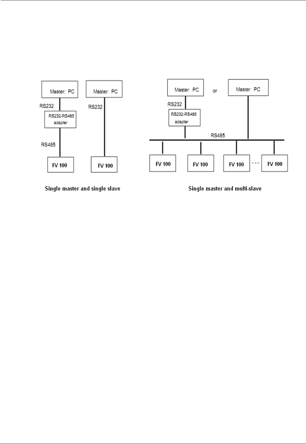
118
118
Communication Protocol
1. Networking Mode
According to the following pic 10-1, there are two networking modes: Single master and multi-slave, Single master
and single slave.
Pic 10-1
2. Interfaces
RS485 or RS232: asynchronous, semi-duplex
Default: 8-N-1, 9600bps, RTU. See Group b3 for parameter settings.
3. Communication Modes
1. The communication protocol for the drive is Modbus. It support normal reading and writing of the registers, also
supports managing the function code.
2. The drive is a slave in the network. It communicates in “point to point” mode.
3. When there is multi-station communication or the communication distance is long, please connect a 100~200 ohm
resistance to the positive and minus terminal of the master’s signal wire in parallel.
4.FV 100 normally provides RS485 interface, if you need RS232, please choose to add a RS232/RS485 conversion
equipment.
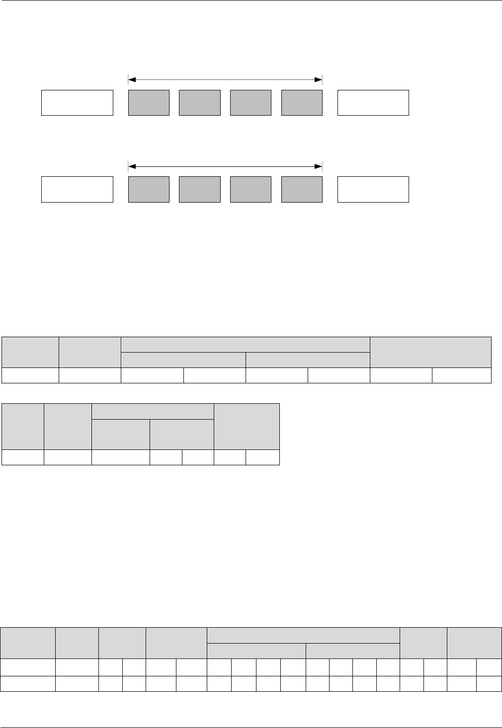
119
119
4. Protocol Format
FV100 support Modbus RTU and ASCII, its frame format is shown in Fig.10-2.
Fig.10-2 Modbus protocol format
Modbus use “Big Endian” of encoder mode,which means sending data with high byte in front and low byte behind.
1. RTU mode
In RTU mode,there must be a idle of at least 3.5 characters between two frames.It use CRC-16 for data check.
Following is an example for read the parameter of internal register 0101(A1.01) from No.5 slave.
Request frame:
Slave
address
Function
code
Data Checksum
Register address Length
0x05 0x03 0x01 0x01 0x00 0x01 0xD5 0xB2
Response frame:
Slave
address
Function
code
Data
Checksum
Response
length
Register
content
0x05 0x03 0x02 0x13 0x88 0x44 0xD2
Therein, checksum is CRC value.
2.ASCII mode
In ASCII mode, characters are used to start and end a frame. The colon “0x3A” is used to flag the start of a message
and each message is ended with a “0x0D,0x0D” combination. Except frame header and end of frame,all other
messages are coded in hexadecimal values, represented with readable ASCII characters. Only the characters 0...9 and
A...F are used for coding. Herein the data use LRC as error checksum.
Following is an example for writing value 4000(0x0FA0) into the parameter of internal register 0201(A2.01) from
No.5 slave.
Request frame:
Frame
header
Slave
address
Function
code
Data Check
code Frame trail
Register address Setting value
Character : 0 5 0 6 0 2 0 1 0 F A 0 4 3 CR LF
ASCII 3A 30 31 30 36 30 32 30 31 30 46 41 30 34 33 0D 0A
Therein,the check code is LRC checksum,which value is equal to the complement of (05+06+02+01+0x0F+0xA0).
Start(The space of
the frame is 3.5
characters at least)
Slave
address
Function
code Data Check sum
End(The space of
frame is 3.5
characters at least)
Modbus Mode
RTU Format
Start
(
0x3A
)
Slave
address
Function
code Data Check sum End
(0x0D,ETX bytes)
Modbus Frame
ASCII Mode
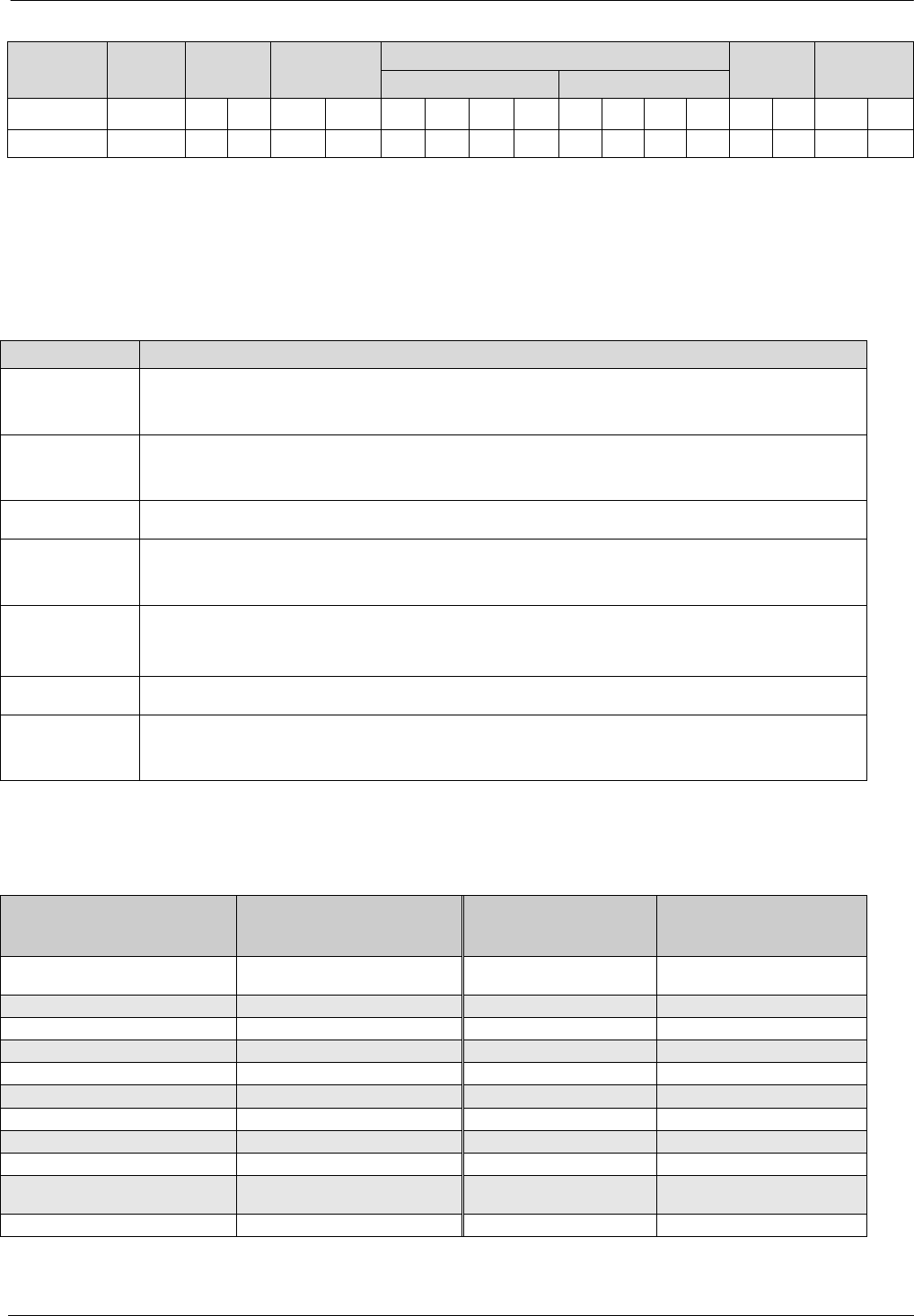
120
120
Response frame:
Frame
header
Slave
address
Function
code
Data Check
code Frame trail
Register address Setting value
Character : 0 5 0 6 0 2 0 1 0 F A 0 4 3 CR LF
ASCII 3A 30 31 30 36 30 32 30 31 30 46 41 30 34 33 0D 0A
VFD can set different delay time for response according to different application.For RTU mode,the actual delay time
for response is 3.5 characters interval at least.For ASCII mode,the actual delay time for response is 1 ms at least.
5. Protocol Function
The main functions of Modbus are read and write parameters.Different function codes need different operation
request.The modbus protocol of VFD support the operations in the following table.
Function code Meaning
0x03 Read parameters of VFD,including function code parameters,control parameters and status
parameters.
0x06 Rewrite single function code or control parameter with 16bit length,the value of the
parameter can’t be saved after VFD power off.
0x08 Diagnosis.
0x10 Rewrite multiple function code or control parameters,the value of the parameters can’t be
saved after VFD power off.
0x41 Rewrite single function code or control parameter with 16bit length,the value
can be saved after VFD power off.
0x42 Manage function code of VFD.
0x43 Rewrite multiple function code or control parameters,the value of the parameters can be
saved after VFD power off.
All the function code, control parameters and status parameters of VFD are mapping to the read/write register of
Modbus.The group number of function code is mapping to the high byte of register address and the index address in
the group is mapping to the low byte of register address.The corresponding relationship between group number and
register address is shown in following table.
Group No. High bye of mapping
address
Group No. High bye of mapping
address
Group A0 0x00 Group B2 0x0C
Group A1 0x01 Group B3 0x0D
Group A2 0x02 Group B4 0x0E
Group A3 0x03 Group C0 0x14
Group A4 0x04 Group C1 0x15
Group A5 0x05 Group D0 0x1E
Group A6 0x06 Group D1 0x1F
Group A7 0x07 Group D2 0x20
Group A8 0x08 Group U0 0x5A
Group B0 0x0A Control parameter 0x32
Group B1 0x0B Status parameter 0x33
For example,the register address of function code A3.02 is 0x0302,and the register address of the first control
parameter(Control command 1) is 0x3200.

121
121
6.Control parameters and status parameters of VFD
The control parameters of VFD can achieve the function such as startup,stop,setting operating frequency and so
on.Retrieving the status parameters of VFD can obtain the parameters such as operating frequency,output
current,output torque and so on.
1.Control parameter
The control parameters of VFD are shown in following table.
Register Parameter Name Saved after powered off Note
0X3200 Control word 1 No
0x3201 Main setting No The main setting
frequency: In the common
operation mode, the
channel of main setting is
serial communication, it
tack effects if the bit8 of
control word 1 is set on.
Whether it saves or not
depends on the setting in
A2.03
0x3202 Operation frequency setting No Same as above
0x3203 Digital closed loop setting yes Takes effects after the
closed loop is enabled
0x3204 Pulse closed loop setting / Do not support
0x3205 Analog output AO1 setting No Enable when A6.28=15
0x3206 Analog output AO2 setting No Enable when A6.29=15
0x3207 Digital output DO setting No Enable when A6.25=65
0x3208 Frequency Proportion
setting
Do not support
0x3209 Virtual terminal control
setting
No Bit~bit6:X1~X7.
Corresponding to the ON
state of the bits in A6.24
Bit10~bit13:
Y1/Y2/RO1/RO2,
They are enabled when
A6.14~A6.17=17
0x320A Set the acceleration time Yes
0x320B Set the deceleration time Yes
0x320D Torque Setting No In the torque mode, the
torque setting channel is
serial port
Ox3212 Control command word 2 No
Note:
(1)When read control parameters,it will return the value which is rewrote in the previous communication.

122
122
(2)In control parameters,the preset value,range of input/output setting value and decimal point scaling should
refer to the corresponding function code.
The bits for the control command word 1 are defined as follows:
Bit Va l ue Function Note
bit2~bit0
111B Running command Start VFD(enable when jog is disable)
110B Stop mode 0 Stop according to the preset deceleration
time(enable when jog is disable)
101B Stop mode 1 Coast to stop
100B Stop by external fault Coast to stop and VFD display external
fault
011B Stop mode 2 Not support
Others Reserved
bit3 1 Reverse Set the operating direction when run
command is enable
0 Forward
bit4 1 Jog forward No action when bits for jog forward and
reverse are enable at the same time,and jog
stop when both are disable at the same time.
0 Jog forward disable
bit5 1 Jog reverse
0 Jog reverse disable
bit6 1 Enable Acc/Dec The bit5~bit0 of control word 1 are enable
when this bit is enable.
0 Disable Acc/Dec
bit7 1 Host computer control word 1
enable Selection bit of host computer control word
1
0 Host computer control word 1
disable
bit8 1 Main reference enable Selection bit of main reference
0 Main reference disable
bit9 1 Fault reset enable Selection bit of fault reset
0 Fault reset disable
bit15~bit10 000000B Reserved
Note:
(1)The host computer control word(control word1 and control word 2) is enable when set “Methods of inputting
operating commands” to “communication control”.The control word 1 is enable when the bit7 of control word 1 is
enable.And bit5~bit0 are enable when the bit6 of control word 1 is enable.
(2)Processing of fault and alarm in host computer:when VFD is failure,all the command of control word 1 and
control word 2,except fault reset command,are disable,it need to reset fault firstly before sending other
commands.When the alarm happens,the control words is still enabled.

123
123
The bits definitions of control word 2 are shown as follows:
Bit Va lue Function Note
bit0 1 VFD operation disable Selection bit for VFD operation
enable/disable
0 VFD operation enable
bit1 1 Running(The direction refer to
function code) Running direction
0 Other operation status(Refer to
control word 1)
bit2 1 Auxiliary reference enable
The selection bit for auxiliary
reference frequency.
0 Auxiliary reference disable
bit3 1 The control word 2 enable The selection bit for control word2.
0 The control word 2 disable
bit15~bit4 Reserved
Note: control word 2 is enabling when the bit3 of control word 2 is enable.
2.Status parameters
Register address Parameters name Note
0x3300 VFD operation status word 1
0x3301 Current main reference value Current operating
frequency
0x3302 Slave model
0x3303 VFD model
0x3304 Software version
0x3305 Current operating frequency
0x3306 Output current
0x3307 Output voltage
0x3308 Output power
0x3309 Operating rotary speed
0x330A Operating line speed
0x330B Analog close-loop feedback
0x330C Bus voltage
0x330D External counter Not support
0x330E Output torque
0x330F Digital input/output terminal status bit0~bit6:
X1~X7;
bit10~bit12:
Y1/Y2/RO1。
0x3310 Actual length Not support
0x3311 Operating frequency after compensation Not support
0x3312 The first operating fault
0x3313 The second operating fault
0x3314 The latest operating fault
0x3315 Operating frequency setting
0x3316 Rotary speed setting
0x3317 Analog close-loop setting
0x3318 Line speed setting
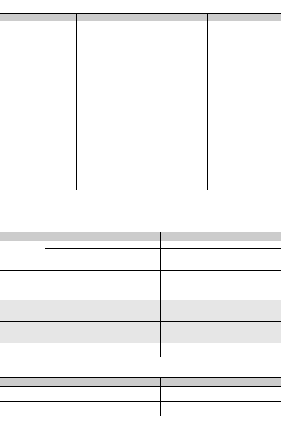
124
124
Register address Parameters name Note
0x3319 AI1
0x331A AI2
0x331B Length setting Not support
0x331C Acceleration time 1 setting
0x331D Deceleration time 1 setting
0x331E Methods of inputting
operating commands
0:Panel control
1:Terminal control
2:Communication control
0x331F VFD operating status word 2
0x3320 Main reference frequency selector
0:Digital setting 1(Keypad ∧∨ setting)
1:Digital setting 2(Terminal UP/DN setting)
2:Digital setting 3 (Serial port)
3:AI analog setting
4:DI pulse setting
5:Expansion card.
0x3321 Accumulated length Not support
Note:
(1)Status parameters don’t support write operation.
(2)The encoding rules of slave model is as follows:the range of slave model is 0~999.
The bit definitions of VFD operating status word 1 are shown in following table:
Bit Va l ue Function Note
bit0 1 VFD running
0 VFD stop
bit1 1 VFD reverse rotation
0 VFD forward rotation
bit2 1 Reach main reference
0 Not reach main reference
bit3 1 Serial port control enable
0 Serial port control disable
bit4 1 Serial port setting enable
0 Serial port setting disable
bit5~bit6 Reserved
bit7 1 Alarm When this bit is 0,the bit15~8 of control word
1show the status.If bit15~8 are 0,means
normal.If not,means failure.
0 Fault or normal
bit15~ bit8 0x00~0xFF Fault/alarm code 0: normal.
Not 0: fault/alarm.
The bit definitions of VFD operating status word 2 are shown in following table:
Bit Va lue Function Note
bit0 1 Jog running
0 Non-jog running
bit1 1 Close loop running
0 Non-close loop running
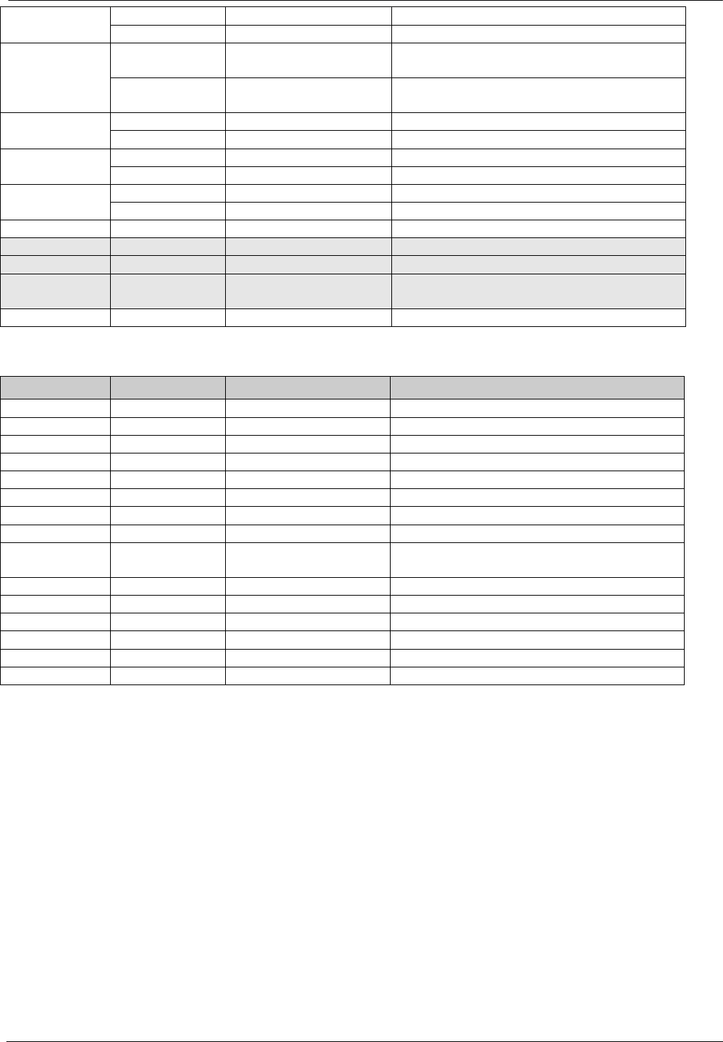
125
125
bit2 1 PLC running
0 Non-PLC running
bit3 1 Multi-section frequency
operation
0 Non multi-section
frequency operation.
bit4 1 Common operation
0 Non-common operation
bit5 1 Swing frequency
0 Non-swing frequency
bit6 1 Under voltage
0 Normal voltage
bit7 Reserved
bit8 Servo operation
bit9 Customized operation
bit10 Synchronous speed
operation
Others Reserved
The bit definitions of VFD operating status word 3 are shown as following table:
Bit Va lue Function Note
bit0~bit1 Reserved
bit2 Zero speed operation
bit3 Accelerating
bit4 Decelerating
bit5 Constant speed running
bit6 Pre-excitation
bit7 Tuning
bit8 Over-current limiting
bit9 DC over-voltage
limiting
bit10 Torque limiting
bit11 Speed limiting
bit12 VFD failure
bit13 Speed control
bit14 Torque control
bit15 Position control
1. Some instructions
1.For function code 0x10 and 0x43,when rewrite multiple continous function codes,if any one of the function
codes is invalid for write operation,then it will return error information and all of the parameters can’t be
rewritten.When rewrite multiple continuous control parameters,if any one of the parameters is invalid for write
operation, then it will return error information and this parameter and others behind can’t be rewritten,but other
parameters before this parameter can be rewritten normally.
2.For some special function code,Using 0x06 and 0x41 or 0x10 and 0x43 are the same function,in write
operation,the parameters can be saved after power failure.

126
126
Function code Description
B4.02 Parameters protection setting
A6.00~A6.07 Selection of input terminal X1~X7
A2.03 Main reference frequency control
A2.03 Auxiliary reference frequency control
C2.00 PLC operation mode
C3.00 Swing frequency operation mode
B0.00 Motor rated power
U0.01 Machine model setting(Factory parameter)
U0.09 VFD series selection(Factory parameter)
3.Some control parameters can’t save in EEPROM,so for these parameters,using function code 0x41 and 0x06 or
0x43and 0x10 are the same,mean parameters can be saved after power failure.
4.Some internal parameters of VFD are reserved and can’t be changed via communication,refer to following
table:
Function code Description
B4.04 Parameters copy
B0.11 Motor parameters auto-tuning
5.The operation of user password and factory password in host computer
(1)User password
1)Protection of user password:read/write function code,function code management(except “read address of
displaydata” and”switch display data”)
2)If you set user password(A0.00!=0),then you must enter the right password to A0.00 when you want to visit
function code,but control parameters and status parameters are not protected by user password.
3)User password can’t be set,change or cancel by host computer,it can only operated by keypad. To A0.00 of
write operation, only effective in two situations: one is in the password decryption; Second,write 0 is in the situation of
no password.It will return invalid operation information in other situations.
4)The operation of host computer and keypad to user password is independent. Even if the keyboard complete
decryption, but host computer still need to decrypt when it want to access function codes, and vice versa.
5)After host computer acquire the access right of parameters,when reading user password,it will return “0000”
instead of actual user password.
6)The host computer will acquire the access right of function code after decryption,if there is no communication
for 5minutes,then the access right will disable.And if it want to access function code,it need to enter user password
again.
7)When host computer has acquired access right(no user password or has decryption),if the user password is
rewritten by keypad at this moment,the host computer has still the current access right and no need to decryption
again.
(2)Factory password
1)Protection range of factory password:read/write parameters of Group U0,function code management of Group
U0.

127
127
2)Host computer can only access function code of Group U0 after decryption(write correct factory password into
U0.00).If there is no communication for 5 minutes after acquiring access right,the right will disable automatically,and
it need to enter password again to access Group U0.
3)After acquiring the access right of Group U0,if host computer read U0.00,it will return 0000 instead of actual
factory password.
4)The operation of host computer and keypad to user password is independent. They need to enter the correct
password separately to acquire the access right.
5)Host computer has no right to modify factory password.When host computer write data into U0.00, it will
return invalid operation unless the data is correct password.
2. Application example
FV100 only support 16bit access.
Start No.5 VFD to perform forward rotation.
Data frame Address Function code Register address Register content Checksum
Request 0x05 0x06 0x3200 0x00C7 0xC764
Response 0x05 0x06 0x3200 0x00C7 0xC764
No.5 VFD stops in mode 0.
Data frame Address Function code Register address Register content Checksum
Request 0x05 0x06 0x3200 0x00C6 0x06A4
Response 0x05 0x06 0x3200 0x00C6 0x06A4
No.5 VFD jogs forward.
Data frame Address Function code Register address Register content Checksum
Request 0x05 0x06 0x3200 0x00D0 0x876A
Response 0x05 0x06 0x3200 0x00D0 0x876A
No.5 VFD stop jogging.
Data frame Address Function code Register address Register content Checksum
Request 0x05 0x06 0x3200 0x00C0 0x86A6
Response 0x05 0x06 0x3200 0x00C0 0x86A6
No.5 VFD reset fault:
Data frame Address Function code Register address Register content Checksum
Request 0x05 0x06 0x3200 0x0280 0x8636
Response 0x05 0x06 0x3200 0x0280 0x8636
Read the operating frequency of No.5 VFD and the response operating frequency of the VFD is 50.00Hz:
Data frame Address Function code Register
address
Number of
registers or
bytes
Register
content
Checksum
Request 0x05 0x03 0x3301 0x0001 None 0xDB0A
Response 0x05 0x03 None 0x02 0x1388 0x44D2
Rewrite the acceleration time 1(Function code A0.06) of No.5 VFD to 10.0s and can’t save after power failure.

128
128
Data frame Address Function code Register address Register content Checksum
Request 0x05 0x06 0x0006 0x0064 0x69A4
Response 0x05 0x06 0x0006 0x0064 0x69A4
Read the output current of No.5 VFD and the response output current of the VFD is 30.0A.
Data frame Address Function code Register
address
Number of
registers or
bytes
Register
content
Checksum
Request 0x05 0x03 0x3306 0x0001 None 0x6ACB
Response 0x05 0x03 None 0x02 0x012C 0x49C9
Read the deceleration time 1(Function code A0.07) of No.5 VFD and the response deceleration time of the VFD
is 6.0s.
Data frame Address Function code Register
address
Number of
registers or
bytes
Register
content
Checksum
Request 0x05 0x03 0x0007 0x0001 None 0x344F
Response 0x05 0x03 None 0x02 0x003C 0x344F
Scaling relationship of VFD:
A)Scaling of frequency C is 1:100.
If you want to make the VFD run at 50Hz,then the main reference should be set as 0x1388(5000).
B)Scaling of time is 1:10
If you want to set the acceleration time of the VFD as 30s,then the function code should be set as 0x012C(300).
C)Scaling of current is 1:10
If the response current of VFD is 0x012C (300), then current of the VFD is 30A.
D)Output power is the absolute value.
E)Other (such as the input and output terminals, etc.) please reference inverter user manual
