UAM_Manual_C6100003_3_en UAM Manual C6100003 3 En
User Manual:
Open the PDF directly: View PDF ![]() .
.
Page Count: 155 [warning: Documents this large are best viewed by clicking the View PDF Link!]
- 1. Introduction
- 2. Safety precautions
- 3. Product overview
- 3.1 Features of UAM-05LP
- 3.2 Components of UAM-05LP
- 3.3 Operation principle
- 3.4 Scanning area
- 3.5 Area switching
- 3.6 Incremental encoder
- 3.7 OSSD
- 3.8 External device monitoring (EDM) function
- 3.9 Muting function
- 3.10 Reference monitoring function
- 3.11 Area sequence function
- 3.12 Response time
- 3.13 Other outputs
- 3.14 Information indicator
- 3.15 Ethernet communication
- 3.16 Function to configure UAM by SD card
- 3.17 Master-Slave Function
- 3.18 Laser Off Mode
- 3.19 Scan Skip Function
- 3.20 Optical Window Contamination Warning Function
- 4. Application examples of UAM
- 4.1 Access protection (Horizontal application Stationary Protection zone 1)
- 4.2 Access protection (Stationary Horizontal application with Dual Protection zone)
- 4.3 Access protection (Vertical application- whole body detection)
- 4.4 Access protection (Vertical application Stationary)
- 4.5 Area protection (Horizontal application Mobile) Fixed area
- 4.6 Area protection (Mobile, Horizontal, Single Protection, Variable Area)
- 4.7 Area protection (Mobile, Horizontal, Single Protection, Encoder Input)
- 4.8 Area protection (Mobile, Horizontal, 2 Units Interconnected, Variable Area)
- 4.9 Area protection (Mobile, Horizontal, 4 Units Interconnected, Variable Area)
- 4.10 Area protection (Mobile, Horizontal, Autonomous Navigation)
- 4.11 Default Values
- 5. Installation
- 6. Wiring
- 7. Function configuration of UAM
- 7.1 About UAM Project Designer application
- 7.2 System requirements
- 7.3 Installatiion of UAM Project Designer
- 7.4 Device driver installation
- 7.5 Starting the UAM Project Designer
- 7.6 Components of UAM Project Designer
- 7.7 Menu bar
- 7.8 Tool bar
- 7.9 Subpanel
- 7.10 Status bar
- 7.11 Connecting UAM with PC
- 7.12 Password
- 7.13 Configuration mode
- 7.14 Function configuration
- 7.15 Area configuration
- 7.16 Transmit configurations to UAM
- 7.17 Save project file
- 7.18 Read configuration from UAM
- 7.19 Open project file
- 7.20 Recording the UAM data
- 7.21 Replay the log data
- 7.22 Save settings to SD card
- 7.23 UAM configuration through SD card
- 8. Inspection and maintenance
- 9. Troubleshooting
- 10. Specification
- 11. Package contents
- 12. Options
- 12.1 Base mounting bracket (Model: UAM-BK03)
- 12.2 Rear mounting bracket (Model: UAM-BK04)
- 12.3 USB cable (Model: UAM-MUSB)
- 12.4 Ethernet cable (Model: UAM-ENET)
- 12.5 Configuration CD (Model: UAM-CD03)
- 12.6 Optical window for replacement (Model: UAM-W002)
- 12.7 Cover Bracket (Type: UAM-BK05)
- 12.8 Connector Cable (UAM-05LP-T301C Only)
- 13. External dimension
- 14. EC Declaration of conformity
- 15. Revision history
- 16. Representative contacts
Safety Laser Scanner
UAM-05LP
User’s Manual
Document No: C-61-00003-3

1
Document No: C-61-00003-3
Table of contents
1. Introduction ................................................................................................................................................. 6
1.1 About this manual ................................................................................................................................. 6
1.2 Applicable products ............................................................................................................................... 6
1.3 Abbreviations ......................................................................................................................................... 6
1.4 Special markings and symbols ............................................................................................................. 6
1.5 Applicable directives and standards .................................................................................................... 7
1.6 Registered trademarks .......................................................................................................................... 7
2. Safety precautions ....................................................................................................................................... 8
2.1 General precautions .............................................................................................................................. 8
2.2 Operating environment ......................................................................................................................... 9
2.3 Installation of UAM............................................................................................................................... 9
2.4 Wiring ..................................................................................................................................................... 9
2.5 Configuration ....................................................................................................................................... 10
2.6 Inspection and maintenance ............................................................................................................... 10
3. Product overview ....................................................................................................................................... 12
3.1 Features of UAM-05LP ....................................................................................................................... 12
3.2 Components of UAM-05LP ................................................................................................................ 13
3.3 Operation principle ............................................................................................................................. 15
3.4 Scanning area ....................................................................................................................................... 16
3.4.1 Protection zone ............................................................................................................................... 16
3.4.2 Warning zone ................................................................................................................................. 18
3.5 Area switching ...................................................................................................................................... 19
3.6 Incremental encoder ............................................................................................................................ 23
3.6.1 Pulse per cm travel generated by incremental encoders ............................................................ 24
3.6.2 Recommend incremental encoder specification .......................................................................... 25
3.6.3 Tolerances allowed for encoder .................................................................................................... 25
3.6.4 Area switching by encoder input .................................................................................................. 26
3.7 OSSD .................................................................................................................................................... 27
3.7.1 Self-diagnostic function of OSSD ................................................................................................. 28
3.7.2 Lockout state .................................................................................................................................. 28
3.7.3 Interlock function .......................................................................................................................... 29
3.8 External device monitoring (EDM) function .................................................................................... 31
3.9 Muting function ................................................................................................................................... 32
3.9.1 Muting start condition................................................................................................................... 32
3.9.2 Muting stop condition ................................................................................................................... 33
3.9.3 Muting override function .............................................................................................................. 34
3.10 Reference monitoring function ......................................................................................................... 35
3.10.1 Area protection............................................................................................................................. 35

Document No: C-61-00003-3
2
3.10.2 Access protection .......................................................................................................................... 36
3.11 Area sequence function...................................................................................................................... 38
3.12 Response time .................................................................................................................................... 38
3.13 Other outputs ..................................................................................................................................... 39
3. 13.1 Warning output 1 (WARNING 1) .............................................................................................. 39
3. 13.2 Warning output 2 (WARNING 2) .............................................................................................. 39
3. 13.3 Muting output 1 (MUT_OUT 1) ................................................................................................ 39
3. 13.4 Muting output 2 (MUT_OUT 2) ................................................................................................ 39
3. 13.5 Reset Request 1 (RES _ REQ1) ................................................................................................. 40
3.13.6 Reset Request 2 (RES _ REQ2) .................................................................................................. 40
3.14 Information indicator ........................................................................................................................ 40
3.14.1 LED ............................................................................................................................................... 41
3.14.2 7-Segment display ........................................................................................................................ 41
3.15 Ethernet communication................................................................................................................... 42
3.15.1 Ethernet Setting ........................................................................................................................... 42
3.16 Function to configure UAM by SD card .......................................................................................... 43
3.17 Master-Slave Function ...................................................................................................................... 43
3.18 Laser Off Mode .................................................................................................................................. 45
3.19 Scan Skip Function ............................................................................................................................ 45
3.20 Optical Window Contamination Warning Function ...................................................................... 46
4. Application examples of UAM .................................................................................................................. 47
4.1 Access protection (Horizontal application Stationary Protection zone 1) ...................................... 47
4.2 Access protection (Stationary Horizontal application with Dual Protection zone) ........................ 49
4.3 Access protection (Vertical application- whole body detection) ...................................................... 50
4.4 Access protection (Vertical application Stationary) .......................................................................... 52
4.5 Area protection (Horizontal application Mobile) Fixed area .......................................................... 54
4.6 Area protection (Mobile, Horizontal, Single Protection, Variable Area) ........................................ 57
4.7 Area protection (Mobile, Horizontal, Single Protection, Encoder Input) ....................................... 58
4.8 Area protection (Mobile, Horizontal, 2 Units Interconnected, Variable ......................................... 58
4.9 Area protection (Mobile, Horizontal, 4 Units Interconnected, Variable Area) .............................. 59
4.10 Area protection (Mobile, Horizontal, Autonomous Navigation) ................................................... 60
4.11 Default Values .................................................................................................................................... 60
5. Installation ................................................................................................................................................. 62
5.1 Light interference ................................................................................................................................ 62
5.2 Mutual interference ............................................................................................................................. 63
5.3 High reflective background ................................................................................................................ 65
5.4 Limited detection capability zone ...................................................................................................... 66
6. Wiring ......................................................................................................................................................... 67

3
Document No: C-61-00003-3
6.1 Precautions ........................................................................................................................................... 67
6.2 Power supply ........................................................................................................................................ 67
6.3 Wire color and function ...................................................................................................................... 67
6.4 Wiring example .................................................................................................................................... 68
6.5 Input/ Output circuit ........................................................................................................................... 73
6.5.1 OSSD/ Warning Output circuit .................................................................................................... 73
6.5.2 Other output circuits ..................................................................................................................... 73
6.5.3 Input circuit.................................................................................................................................... 74
7. Function configuration of UAM ............................................................................................................... 75
7.1 About UAM Project Designer application ......................................................................................... 75
7.2 System requirements ........................................................................................................................... 75
7.3 Installatiion of UAM Project Designer .............................................................................................. 76
7.3.1 Uninstallation UAM Project Designer ......................................................................................... 76
7.4 Device driver installation .................................................................................................................... 77
7.4.1 Installing the driver in Windows 8 ............................................................................................... 77
7.4.2 Installing the driver in Windows 7 ............................................................................................... 79
7.4.3 Installing the driver in Windows XP ............................................................................................ 84
7.4.4 Installing the driver in Windows 10 ............................................................................................. 84
7.5 Starting the UAM Project Designer ................................................................................................... 85
7.5.1 Startup Main window .................................................................................................................... 85
7.5.2 Create new configuration .............................................................................................................. 86
7.5.3 Open configuration file ................................................................................................................. 87
7.5.4 Connect to UAM ............................................................................................................................ 87
7.6 Components of UAM Project Designer ............................................................................................. 88
7.7 Menu bar .............................................................................................................................................. 89
7.7.1 File ................................................................................................................................................... 89
7.7.2 Edit .................................................................................................................................................. 89
7.7.3 Mode ............................................................................................................................................... 90
7.7.4 Connection...................................................................................................................................... 90
7.7.5 Option ............................................................................................................................................. 91
7.7.6 Language ........................................................................................................................................ 91
7.7.7 Help ................................................................................................................................................. 92
7.8 Tool bar................................................................................................................................................. 93
7.9 Subpanel ............................................................................................................................................... 94
7.9.1 Configuration tab .......................................................................................................................... 94
7.9.2 Monitor tab .................................................................................................................................. 105
7.9.3 Report tab..................................................................................................................................... 105
7.10 Status bar ......................................................................................................................................... 108
7.11 Connecting UAM with PC .............................................................................................................. 108

Document No: C-61-00003-3
4
7.12 Password .......................................................................................................................................... 109
7.12.1 Changing the password ............................................................................................................. 109
7.12.2 Reclaim the forgotten password ............................................................................................... 110
7.13 Configuration mode ........................................................................................................................ 110
7.14 Function configuration .................................................................................................................... 111
7.15 Area configuration ........................................................................................................................... 112
7.15.1 Area configuration by drawing tools ........................................................................................ 113
7.15.2 Area configuration by teaching function ................................................................................. 115
7.15.3 Muting configuration ................................................................................................................ 117
7.15.4 Reference region configuration ................................................................................................ 118
7.16 Transmit configurations to UAM ................................................................................................... 119
7.17 Save project file ............................................................................................................................... 120
7.18 Read configuration from UAM ...................................................................................................... 122
7.19 Open project file .............................................................................................................................. 122
7.20 Recording the UAM data ................................................................................................................ 123
7.21 Replay the log data .......................................................................................................................... 124
7.22 Save settings to SD card .................................................................................................................. 126
7.23 UAM configuration through SD card ............................................................................................ 127
8. Inspection and maintenance ................................................................................................................... 128
8.1 Pre-operation inspection ................................................................................................................... 128
8.2 Operation inspection ......................................................................................................................... 129
8.3 Daily inspection ................................................................................................................................. 130
8.4 Periodical inspection ......................................................................................................................... 131
8.5 Cleaning the optical window............................................................................................................. 133
8.6 Replacing the optical window ........................................................................................................... 134
8.6.1 Method of replacing the optical window.................................................................................... 134
8.6.2 Adjustment of the optical window .............................................................................................. 135
9. Troubleshooting ....................................................................................................................................... 137
10. Specification ........................................................................................................................................... 141
10.1 UAM-05LP ....................................................................................................................................... 141
11. Package contents .................................................................................................................................... 144
12. Options ................................................................................................................................................... 145
12.1 Base mounting bracket (Model: UAM-BK03) .............................................................................. 145
12.2 Rear mounting bracket (Model: UAM-BK04) .............................................................................. 145
12.3 USB cable (Model: UAM-MUSB) .................................................................................................. 145
12.4 Ethernet cable (Model: UAM-ENET) ........................................................................................... 145
12.5 Configuration CD (Model: UAM-CD03) ....................................................................................... 145
12.6 Optical window for replacement (Model: UAM-W002) .............................................................. 146

5
Document No: C-61-00003-3
12.7 Cover Bracket (Type: UAM-BK05) ............................................................................................... 146
12.8 Connector Cable (UAM-05LP-T301C Only) ................................................................................ 146
13. External dimension................................................................................................................................ 147
13.1 UAM-05LP ....................................................................................................................................... 147
13.2 Base mounting bracket ................................................................................................................... 148
13.3 Rear mounting bracket ................................................................................................................... 149
13.4 Cover Protection Bracket ............................................................................................................... 150
14. EC Declaration of conformity .............................................................................................................. 151
15. Revision history ..................................................................................................................................... 153
16. Representative contacts......................................................................................................................... 154
Document No: C-61-00003-3
6
1. Introduction
This user’s manual is designed with the purpose of providing guidelines and instructions for the machine
user or system designer while operating, installing, wiring and servicing the UAM-05LP.
1.1 About this manual
UAM’s features, installation and handling method are described in this document.
Read this document carefully before installation, wiring, operation, inspection and maintenance.
User should have a copy of this document at an easy-to-access place for quick reference.
Information provided in this document is subject to change without prior notice. For the latest
information visit the company’s website http://www.hokuyo-aut.jp
Actual product may differ from the illustrations and figures in this document as they are used for
explanatory purpose only.
1.2 Applicable products
This document is for the following sensor model.
UAM-05LP-T301
UAM-05LP-T301C
1.3 Abbreviations
The list below shows abbreviations used in this document.
Table 1-1 Abbreviations
Abbreviation Meaning
AGV Automated guided vehicle
AOPDDR Active optoelectronic protective device responsive to diffuse reflection
AWG American wire gage
EDM External device monitoring
EMC Electromagnetic compatibility
MSCE Machine secondary control element
OSSD Output signal switching device
SELV Safety extra low voltage
1.4 Special markings and symbols
Markings and symbols are used in this document to alert the user about safety-related issues. Follow the
instructions of these special markings and symbols to ensure safety during the operation.
7
Document No: C-61-00003-3
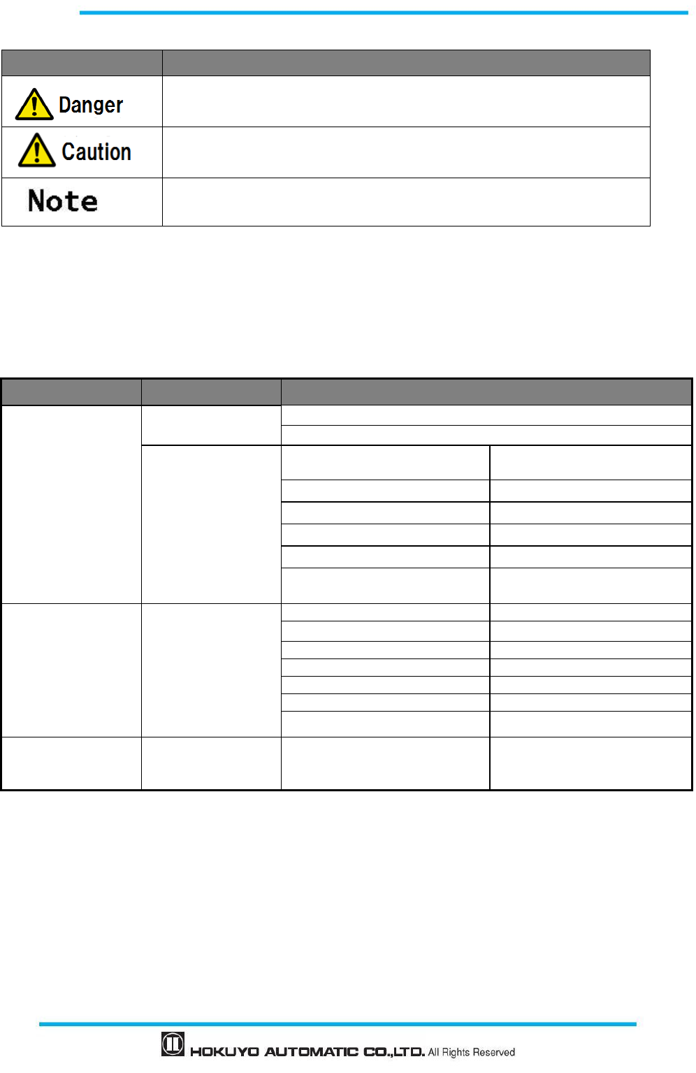
Table 1-2 Special markings and symbols
Mark Meaning
Procedures that could lead to dangerous situation, critical injury or death if not
carried out properly
Procedures that could lead to dangerous situation, serious injury or physical
damage if not carried out properly
Points that should be considered for the proper operation
1.5 Applicable directives and standards
UAM is certified by TUV SUD Product Service GmbH and UL/c-UL, FDA (CDRH) as a safety sensor
defined in EU Machine Directive (2006/42/EC).
Table 1-3 Applicable directives and standards
Certified authority Directives/Standard
Details
TUV SUD
EU directives Machinery Directive: Directive 2006/42/EC
EMC Directive: Directive 2014/30/EU
EN standards
IEC standards
ISO standards
IEC61496-1:2012
EN 61496
-
1:2013
Type 3
IEC 61496-3:2008 Type 3
IEC 61508 Part1-7:2010 SIL2
EN 62061:2005/A2: :2015 SIL2
EN ISO13849-1:2015 Category 3, PLd
IEC60825-1:2014 Safety of laser products
Class 1
UL/c-UL
UL standards
IEC standards
ISO standards
CSA standards
UL 508:2010
ANSI/UL 1998:2013
IEC 61496
-
1:2012
Type 3
IEC 61496
-
3:2008
Type 3
IEC 61508 Part1
-
7:2010
SIL2
ISO13849
-
1:2006
Category 3, PLd
CSA C22.2 No.14-13 :2013
FDA (CDRH) 21 CFR Part 1040.10
and 1040.11 Safety of laser products Class 1
1.6 Registered trademarks
Microsoft
Ⓡ
, Windows
Ⓡ
are the registered trademarks of Microsoft Corporation USA.
Pentium
Ⓡ
is the registered trademark of Intel Corporation.
Other products mentioned in the document are trademarks or registered trademarks of the respective
companies.
Document No: C-61-00003-3
8
2. Safety precautions
2.1 General precautions
UAM is designed to protect human begins or systems by monitoring the hazardous area. It is not
designed for the protection from high speed objects or the electromagnetic radiation.
Perform pre-operation tests in order to verify the performance of UAM.
Do not modify or disassemble UAM. Such modifications will affect the detection capability leading to
injuries or death.
Do not modify or disassemble UAM to maintain its housing rating. Such modifications will void the
warranty.
The person-in-charge should be qualified to operate UAM. The person must be trained, on safety
requirements with necessary cautions for handling the device.
The person-in-charge should train the user with correct installation, operation, inspection and
maintenance procedures.
The person-in-charge is responsible to ensure the proper working environment for UAM.
The person-in-charge is responsible for the compliance with the local safety requirements, standards,
rules and regulations, laws of respective nations, states or districts when UAM is used in a
safety-related system.
UAM has been manufactured and shipped under the strict quality control. If you find any defect in the
product contact the nearest distributor or sales representative. (Last page)
Hokuyo cannot be held responsible for the damages or failure due to misuse of the product.
User should prepare test pieces for detection capability verification. The test piece should emulate the
smallest object that is intended to be detected during the operation.
Maximum level of homogeneous pollution for UAM to operate normally is under 30%. UAM will
report error if the pollution exceeds the stated limit. Always keep the optical window in clean condition
to avoid the error.
Before resetting the interlock of UAM, user must ensure the surrounding is safe especially the protected
area.
Apply sufficient measures to ensure safety of the protected area when decommissioning UAM.
Protective materials such as guards or light curtain should be used to prevent the passage to the
hazardous area.
UAM including its accessories are subject to change without prior notice for the improvement.
UAM should be disposed as industrial waste or in accordance with the local disposal directives.
Read the following guidelines
for correct use of the UAM. Proper handling and
usage will ensure the UAM to operate accordingly.

9
Document No: C-61-00003-3
2.2 Operating environment
Make sure that UAM’s operating environment is within the stated specification (temperature, humidity,
vibration, ambient light, etc.)
Do not use or mount UAM near devices that could generate strong electromagnetic waves as it could
affect the operation of UAM.
Do not use or mount UAM in dusty, smoky, or misty environments, or where corrosive substances are
present. Operating under such environments may decrease the detection capacity of UAM.
This product is for indoor use only.
2.3 Installation of UAM
Install UAM on a firm surface or structure to avoid displacement.
UAM should be firmly mounted using the screws (recommended torque for screws is 3N.m.). Shock
and vibration should not loosen the mounting. Detection may fail if actual protection zone differs from
the intended zone due to displacement of UAM.
Safety distance should be determined before installing UAM. User must verify the function of UAM
after installation by placing a test piece at all the positions of protection zone (refer to chapter 4 for the
details on the safety distance calculation for various applications).
When installing the UAM, protective materials such as guards or light curtain should be used to prevent
any passage into the hazardous area.
Reset switch used for interlock, muting and override function should be mounted at a location away
from the protection zone.
Mutual interference can occur when identical UAMs are mounted at the same detection plane. Refer to
chapter 5 for countermeasures to avoid mutual interference.
UAM should be mounted at the location which has sufficient space for maintenance.
Do not add any protective materials such as, glass and transparent cover, in front of the optical window.
This could lead to loss of detection capability of the UAM.
Minimum detectable width varies with the distance. Refer to chapter 10 for details.
2.4 Wiring
Switch off all the power supplies during wiring.
When a converter is used for supplying the power, make sure it fulfills the following requirements.
A rated output voltage within the range of DC 24V±10% (SELV circuit, Category II).
Reinforced insulation or double insulation for the primary and secondary circuit.
Holding time of the output should be above 20ms.
The power supply complies with the requirements of electromagnetic compatibility
regulations (EMC) of the respective country, state and district.
All the input/output signal cables should be installed away from machines power lines and high-
voltage cables.

Document No: C-61-00003-3
10
Use the OSSD signal of UAM to control safety-related machines or control system. Do not use warning
signals to control safety related machine as these are non safety signals.
Both the OSSD1 and OSSD2 outputs should be connected to the safety-related machines or control
system. If OSSD3 and OSSD4 are used they must be connected in the same manner.
Use shield cable for the connection between OSSD signals and safety-related machines or systems.
Cable length should not exceed the specification.
2.5 Configuration
Configuration of safety functions are password protected. Only authorized users with password are
allowed to configure UAM.
UAM does not operate without initial configuration.
Pre-operation tests should be performed to verify the configurations before operating the UAM.
Increasing the response time of OSSD will increase the stability of UAM. However, this will reduce the
detection capability towards moving objects. User must perform risk assessment before using this
function.
Changes made during the configuration must be recorded and saved. Use the report function in the
UAM Project Designer for this purpose. (page 100)
2.6 Inspection and maintenance
User must perform inspection and maintenance by referring to the checklists provided in this document
(Chapter 8, page 123)
・ Pre-operation inspection
・ Operation inspection
・ Daily inspection
・ Periodic inspection
The checklists in this document are provided as basic guidelines while performing the test and
maintenance. User must perform additional inspection and maintenance tasks deemed necessary for the
respective application.
Stop the machine and system if faults are detected during these tests.
Clean the optical window when it gets contaminated. If the optical window is damaged it should be
replaced by a new one.
For the repair of UAM, contact the nearest distributor or sales representative.
User should not repair or disassemble UAM.
11
Document No: C-61-00003-3
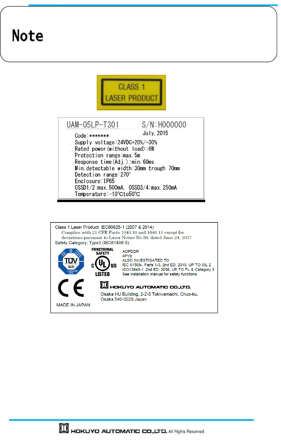
Figure 2-1 Example of product labels
Safety Standard Class 1 Laser of UAM-05LP: It is guaranteed as safety class
laser. Additional measures are not necessary to maintain the laser safety.
Caution - Use of controls or adjustments or performance of procedures other
than those specified herein may result in hazardous radiation exposure.
Document No: C-61-00003-3
12
3. Product overview
UAM emits pulsed laser beam which is reflected on a rotating mirror within the configured protection
zone. When the emitted laser beams are reflected back from an object its distance is measured. This chapter
describes the features and properties of UAM.
3.1 Features of UAM-05LP
Protection range: Maximum 5m (page 136)
Warning range: Maximum 20m (page 136)
Detection angle: 270°(page 15)
Minimum response time of 60ms (Configurable) ( page 39)
32 set of areas (Configurable) *1 (page 20)
2 modes of scanning area setting (page 20)
Dual Protection Mode (Configurable) (page 17)
Scanning area switch through incremental encoder input (Configurable) (page 24)
Interlock function (Configurable) ( page 30)
EDM function (Configurable) ( page 32)
Muting /Override function (Configurable) ( page 33)
Reference monitor function (Configurable) ( page 36)
Area sequence function (Configurable) (page 39)
LED indicator for UAMs status (page 41)
7-segment display (page 42)
Ethernet communication (page 43)
A maximum of 4 sensors for master/slave operation (page 44)
Configuration with SD card (page 44)
Easy configuration with UAM configuration application software installed in PC (page 73)
*1: Depending on the used functions, maximum area varies from 2 to 32 sets of area.
13
Document No: C-61-00003-3
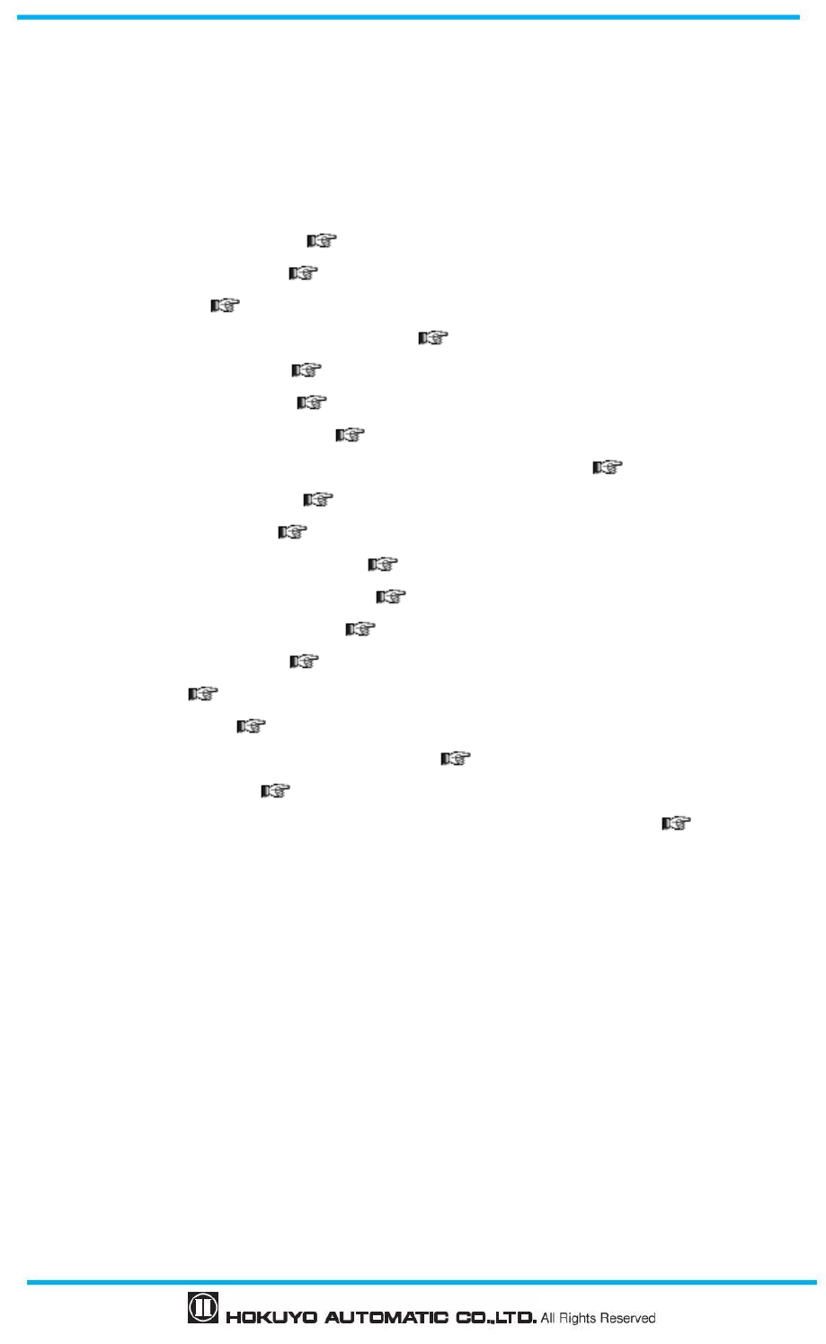
3.2 Components of UAM-05LP
Figure 3-1 UAM-05LP components
Housing
7-segment display Connector Cable
Ethernet Connector
SD card slot
Optical window
USB Connector
Document No: C-61-00003-3
14
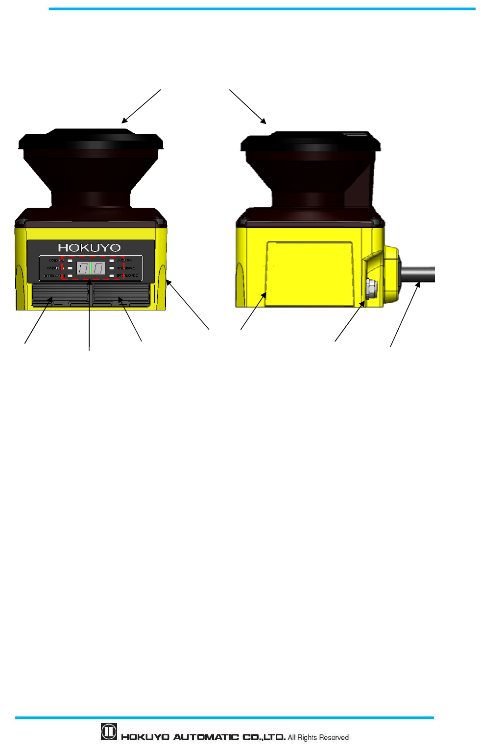
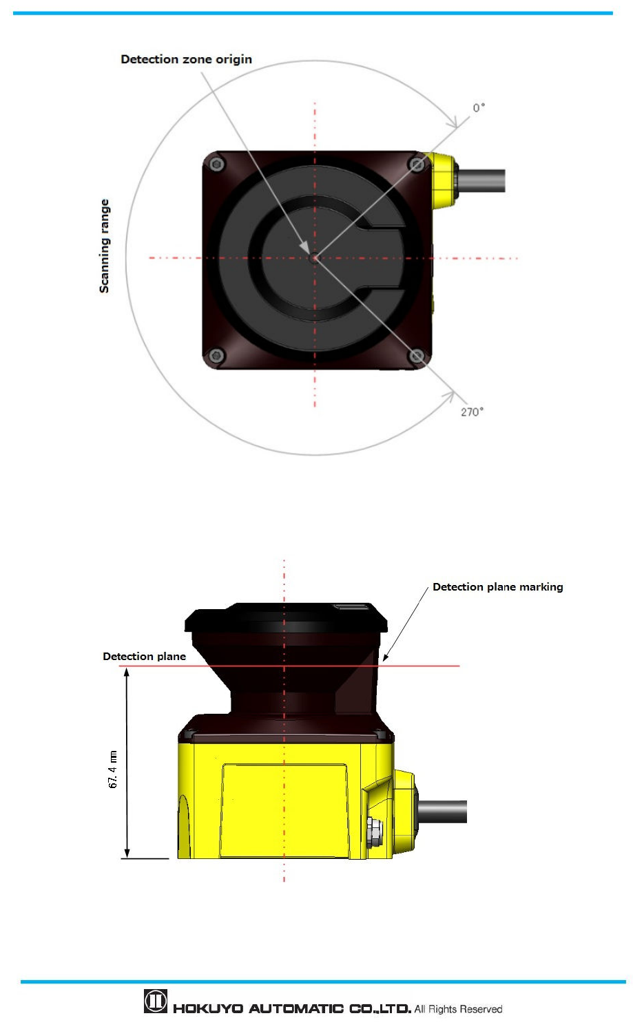
Figure 3-2 Scanning range and detection zone origin (Top view)
Figure 3-3 Detection plane of UAM-05LP (Side view)
15
Document No: C-61-00003-3
3.3 Operation principle
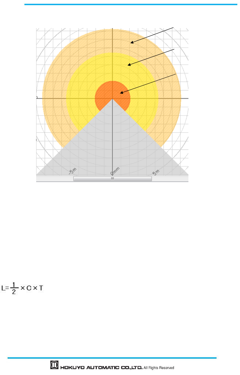
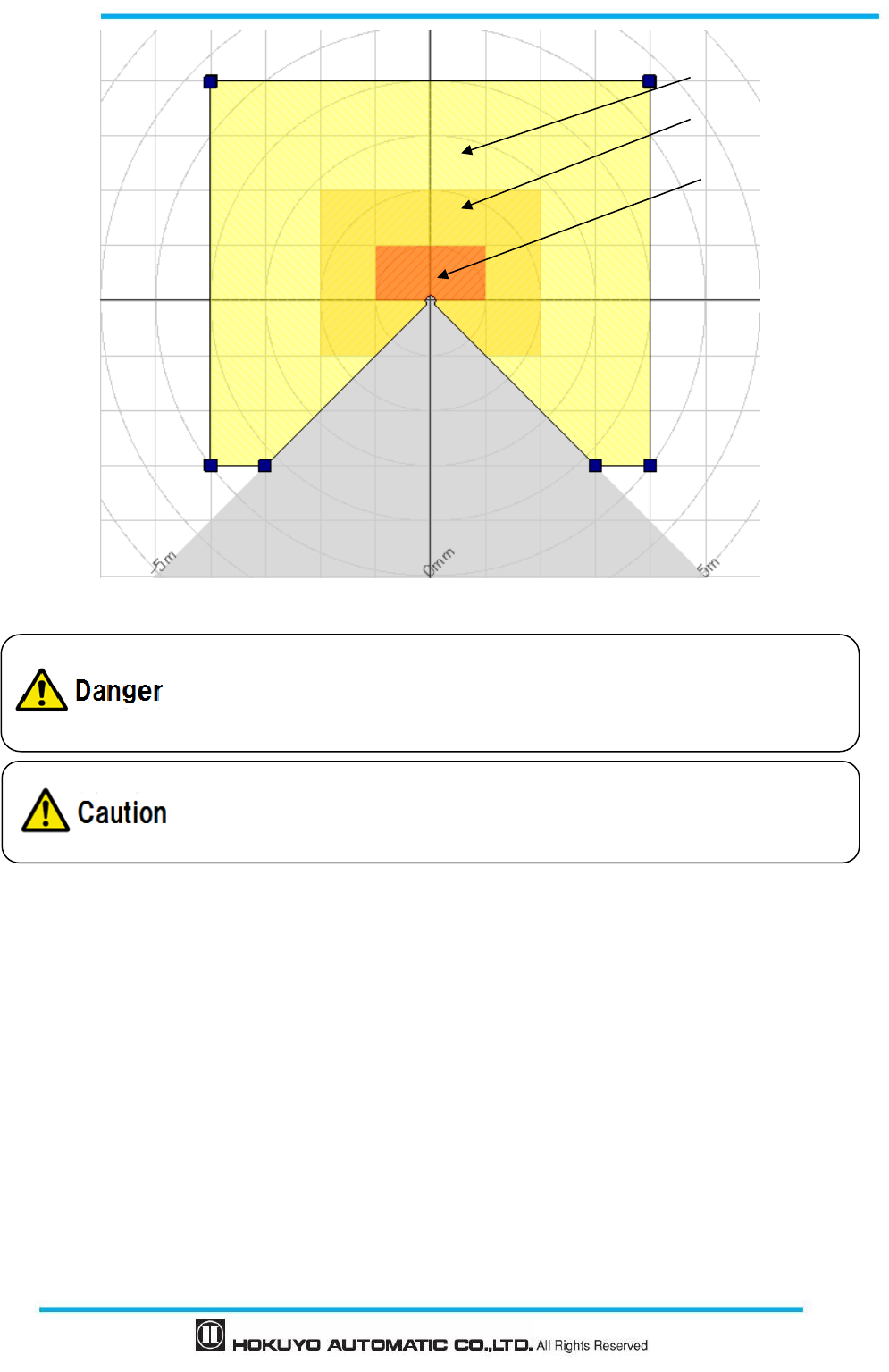
Figure 3-4 Scanning range
Figure 3-4 shows the scanning range of UAM. Protection zone and warning zones are configured using
the UAM Project Designer application software. Any object or human beings entering the protection zone
will lead the OSSD signal to change from ON-state to OFF-state. Similarly, an object detected in the warning
zones will lead the warning signals to change to OFF-state.
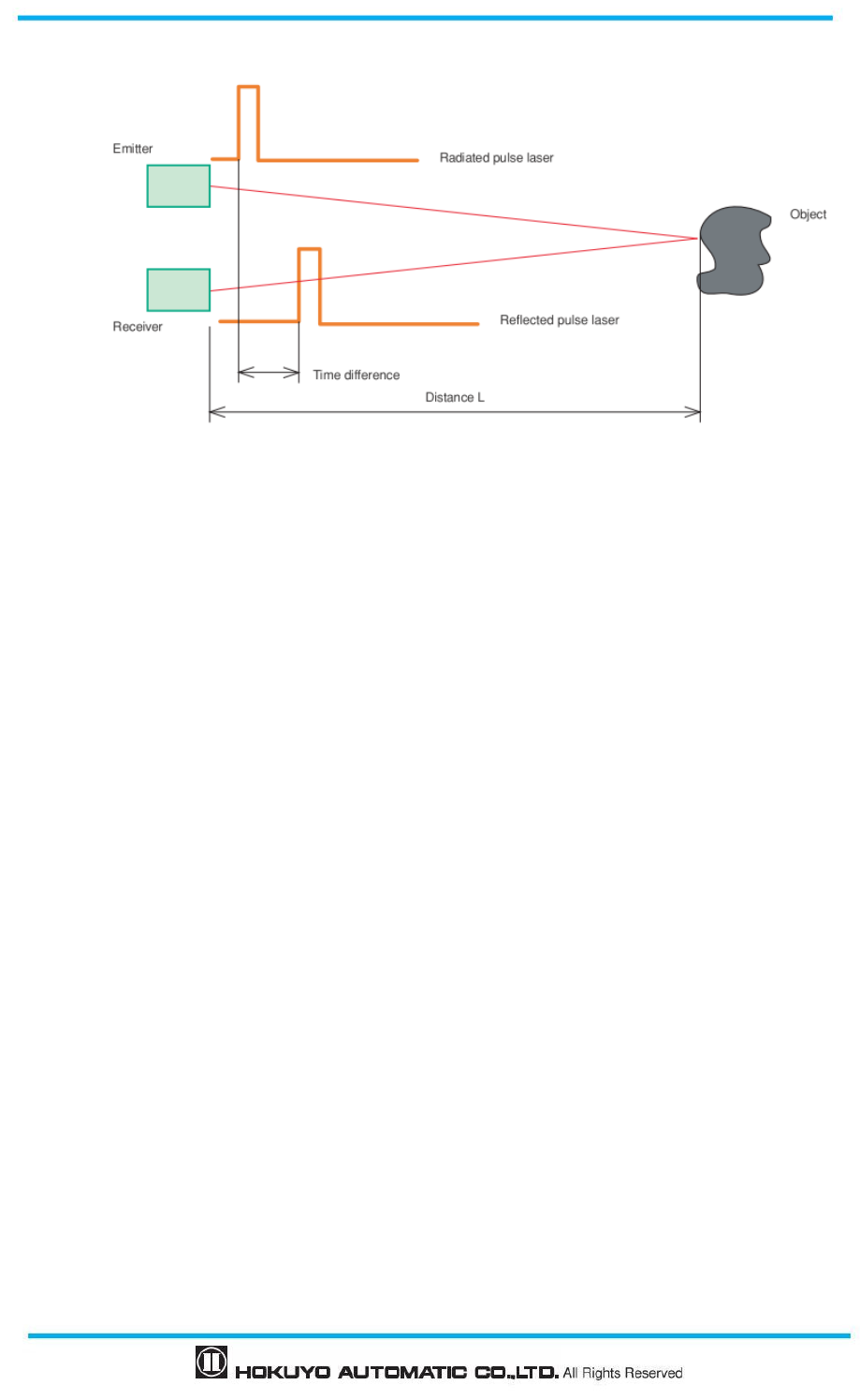
Distance to the object is measured using the Time of Flight (TOF) principle. Pulsed laser beams are
radiated into the scanning range of 270º by the rotating motor. These pulsed laser beams are reflected back
by objects inside the scanning range. The duration of reflected beams are used for distance calculation as
shown below:
Where, L=Distance of the object
C=Speed of the light
T=Time difference
The operating principle of TOF is schematically shown in Figure 3-5. The angular resolution of UAM is
0.125°.
Protection zone
Warning zone 1
Warning zone 2
Document No: C-61-00003-3
16
Figure 3-5 TOF operation principle
3.4 Scanning area
Scanning area of UAM consists of protection zone and warning zones. Maximum 32 sets of area can be
configured. Further, two combinations for protection and warning zones can be selected for the operation.
Combination 1: Protection zone, Warning zone 1 and Warning zone 2
Combination 2: 2 Protection zones (Dual Protection)
In dual protection mode, two protection areas can be configured but it is not possible to configure the
warning zones Protection and warning zones can be configured by using UAM Project Designer. Refer to
Chapter 7 for configuration details.
3.4.1 Protection zone
Protection zone is safety-critical and directly connected to the OSSD signal. When an obstacle is
detected in the protection zone, UAM will switch the OSSD to OFF-state (which should trigger a switch to
stop a machine or AGV). For mobile applications, the OSSD signal can be used as the emergency stop signal.
Figure 3-6 and 3-7 show the examples of protection zone configured using manual mode and teaching mode
respectively. User can configure these zones accordingly to ensure hazardous area is completely protected.
17
Document No: C-61-00003-3
Figure 3-6 Protection zone configured using manual mode
Figure 3-7 Protection zone configured using teaching mode
Figure 3-7 Protection zone configured using teaching mode
User should verify the detection capability using an actual object.
User should verify the configuration before actual operation.
The configured zone should be of minimum safety distance or more.
Minimum possible detectable width changes according to the distance.
Additional distance must be taken into account while configuring the
protection
zone.
Document No: C-61-00003-3
18
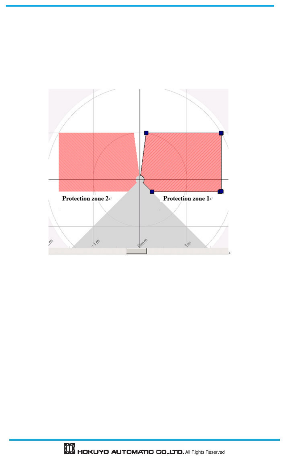
In dual protection mode, two protection zones can be configured independently. UAM will monitor these
zones simultaneously. OSSD1 and OSSD2 are dedicated to protection zone1 and OSSD3 and OSSD4 are
dedicated to protection zone2.
Figure 3-8 shows an example of the dual protection zone configuration. Warning zones cannot be
configured in dual protection mode.
Figure 3-8 Example of Dual protection zone configuration
3.4.2 Warning zone
Warning zones are non-safety zones and are connected to Warning1 and Warning2 outputs. When the
obstacle is detected in the warning zones, UAM will switch the respective warning signal from ON-state to
OFF-state.
Warning signals can be used as an alert signal to avoid human beings or objects from approaching near
the protection zone. For mobile applications, warning signals can be used for reducing the speed of
automatic guided vehicle (AGV) to avoid collision. Figure 3-9 shows an example of warning zone
configuration.
19
Document No: C-61-00003-3
Figure 3-9 Warning zones
3.5 Area switching
A maximum of 32 sets of area can be configured in UAM. However the maximum configurable area
number differs depending on the selected function such as, muting and dual protection. Table 3-1 shows the
maximum configurable area number according to the used mode.
External input signals are provided in UAM for switching the area. Each signal has a pair of normal and
inverted signal. For example, it is necessary to provide both input signal IN_A and inverse IN_A signal to
switch the area. Error will occur if IN_A and inverse IN_A signals do not complement each other. Table 3-2
below shows the combination of input signal to switch the area. Area in use will be displayed in the 7
segment LED of UAM.
It is also possible to configure area input delay. Configure the necessary delay required for the system to
provide stable input signals to UAM. The default value is 30ms.
There are maximum 5 input pairs (a pair is combination of normal and inverted signal) in UAM therefore,
Warning zones are non-safety zones.
Warning signals should not be used for controlling any machine or vehicle for
the
safety-related purposes.
Protection zone
Warning zone 1
Warning zone 2
Warning signals are non safety-signal.
Warning signals and OSSD signal is not inter-related.

Document No: C-61-00003-3
20
it can operate with maximum 32 sets of area. Further, it is also possible to switch the area through the speed
monitoring of incremental encoder signal connected to UAM (page 24).
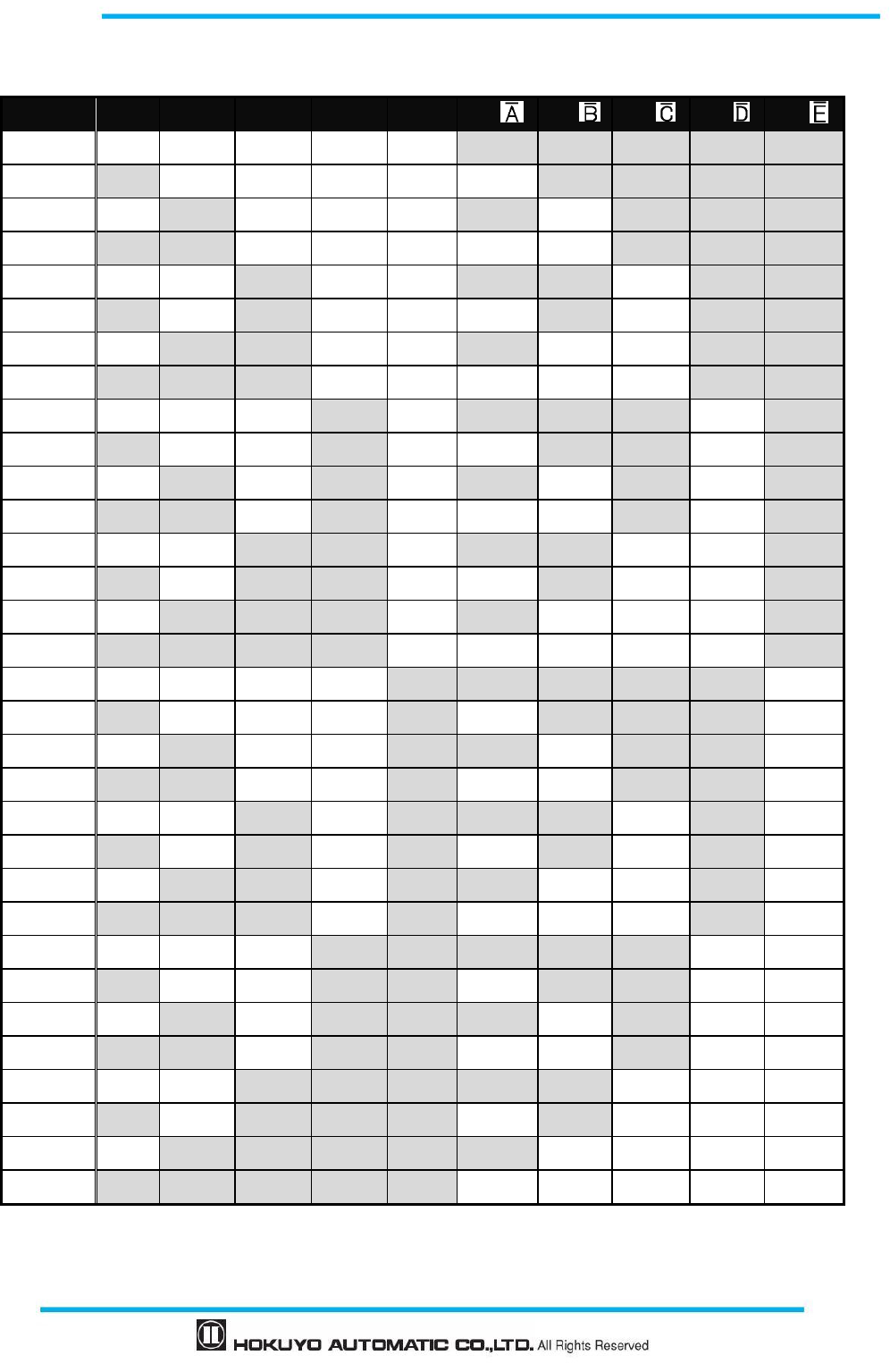
Table 3-1 Input combination for area switching
Mode Protection Max internal input Max Area Max encoder area
Standard 1 5 32 -
2 5 32 -
EDM 1 4 16 -
2 4 16 -
MUTING / EDM
1 2 4 -
2 1 2 -
Encoder *
1
1 2 3 32*2
*
1
: Muting function and dual protection mode cannot be used if encoder input mode is selected.
*2: Among the 4 input patters, at least one pattern must be used for encoder input. Other 3 remaining patterns
can be selected to be used as static input or not in use. A pattern with encoder input mode can have
maximum 32 sets of area (for detail, refer to section 3.6.4).
21
Document No: C-61-00003-3
Table 3-2 Input combination for area switching
a) In the case of 5 input signals
Area IN_A
IN_B IN_C IN_D IN_E
IN_
IN_
IN_
IN_
IN_
Area 1 ON ON ON ON ON OFF OFF OFF OFF OFF
Area 2 OFF
ON ON ON ON ON OFF OFF OFF OFF
Area 3 ON OFF ON ON ON OFF ON OFF OFF OFF
Area 4 OFF
OFF ON ON ON ON ON OFF OFF OFF
Area5 ON ON OFF ON ON OFF OFF ON OFF OFF
Area6 OFF
ON OFF ON ON ON OFF ON OFF OFF
Area7 ON OFF OFF ON ON OFF ON ON OFF OFF
Area8 OFF
OFF OFF ON ON ON ON ON OFF OFF
Area9 ON ON ON OFF ON OFF OFF OFF ON OFF
Area10 OFF
ON ON OFF ON ON OFF OFF ON OFF
Area11 ON OFF ON OFF ON OFF ON OFF ON OFF
Area12 OFF
OFF ON OFF ON ON ON OFF ON OFF
Area13 ON ON OFF OFF ON OFF OFF ON ON OFF
Area14 OFF
ON OFF OFF ON ON OFF ON ON OFF
Area15 ON OFF OFF OFF ON OFF ON ON ON OFF
Area16 OFF
OFF OFF OFF ON ON ON ON ON OFF
Area17 ON ON ON ON OFF OFF OFF OFF OFF ON
Area18 OFF
ON ON ON OFF ON OFF OFF OFF ON
Area19 ON OFF ON ON OFF OFF ON OFF OFF ON
Area20 OFF
OFF ON ON OFF ON ON OFF OFF ON
Area21 ON ON OFF ON OFF OFF OFF ON OFF ON
Area22 OFF
ON OFF ON OFF ON OFF ON OFF ON
Area23 ON OFF OFF ON OFF OFF ON ON OFF ON
Area24 OFF
OFF OFF ON OFF ON ON ON OFF ON
Area25 ON ON ON OFF OFF OFF OFF OFF ON ON
Area26 OFF
ON ON OFF OFF ON OFF OFF ON ON
Area27 ON OFF ON OFF OFF OFF ON OFF ON ON
Area28 OFF
OFF ON OFF OFF ON ON OFF ON ON
Area29 ON ON OFF OFF OFF OFF OFF ON ON ON
Area30 OFF
ON OFF OFF OFF ON OFF ON ON ON
Area31 ON OFF OFF OFF OFF OFF ON ON ON ON
Area32 OFF
OFF OFF OFF OFF ON ON ON ON ON
Document No: C-61-00003-3
22
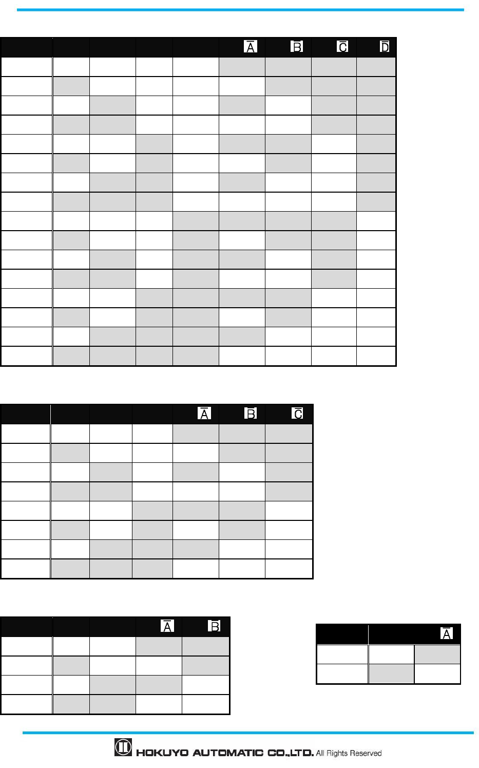
b) In the case of 4 input signals
Area IN_A
IN_B IN_C
IN_D IN_
IN_
IN_
IN_
Area 1 ON ON ON ON OFF OFF OFF OFF
Area 2 OFF
ON ON ON ON OFF OFF OFF
Area 3 ON OFF ON ON OFF ON OFF OFF
Area 4 OFF
OFF ON ON ON ON OFF OFF
Area5 ON ON OFF
ON OFF OFF ON OFF
Area6 OFF
ON OFF
ON ON OFF ON OFF
Area7 ON OFF OFF
ON OFF ON ON OFF
Area8 OFF
OFF OFF
ON ON ON ON OFF
Area9 ON ON ON OFF OFF OFF OFF ON
Area10 OFF
ON ON OFF ON OFF OFF ON
Area11 ON OFF ON OFF OFF ON OFF ON
Area12 OFF
OFF ON OFF ON ON OFF ON
Area13 ON ON OFF
OFF OFF OFF ON ON
Area14 OFF
ON OFF
OFF ON OFF ON ON
Area15 ON OFF OFF
OFF OFF ON ON ON
Area16 OFF
OFF OFF
OFF ON ON ON ON
c) In the case of 3 input signals
Area IN_A
IN_B IN_C
IN_
IN_
IN_
Area 1 ON ON ON OFF OFF OFF
Area 2 OFF ON ON ON OFF OFF
Area 3 ON OFF ON OFF ON OFF
Area 4 OFF OFF ON ON ON OFF
Area5 ON ON OFF OFF OFF ON
Area6 OFF ON OFF ON OFF ON
Area7 ON OFF OFF OFF ON ON
Area8 OFF OFF OFF ON ON ON
d) In the case of 2 input signals
Area IN_A
IN_B IN_
IN_
Area 1
ON ON OFF OFF
Area 2
OFF
ON ON OFF
Area 3 ON OFF OFF ON
Area 4
OFF
OFF ON ON
e) In the case of 1 input signal
Area
IN_A IN_
Area 1 ON OFF
Area 2 OFF ON
23
Document No: C-61-00003-3
3.6 Incremental encoder
In UAM there are 2 pairs of encoder input terminals for connecting 2 units of dual channel incremental
encoder signals. Area will be switched depending on the encoder speed. Direction of travel is detected by
encoder's phase A and phase B signals having the phase difference of 90°. Speed and rotating direction of
both encoders are constantly monitored to detect abnormal travel and stop the AGV.
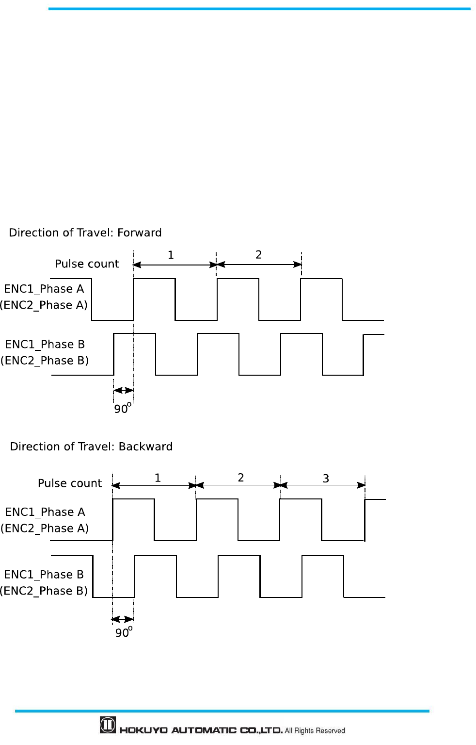
Incremental encoder output signals should be connected to the respective input terminals of UAM. There
are two patterns of signals generated by the combination of Phase A and Phase B of encoders depending on
the direction of travel (Figure 3-10). In the first pattern, Phase B is 90 degrees ahead of Phase A wherein, at
the rising edge of Phase A, state of Phase B is “H”. This pattern is considered as positive direction (forward
motion). In the second pattern, Phase B lags behind Phase A by 90 degrees and the state of Phase B at the
rising edge of Phase A is “L”. This is considered as negative direction (backward motion).
Figure 3-10 Input signals from incremental encoder
Document No: C-61-00003-3
24
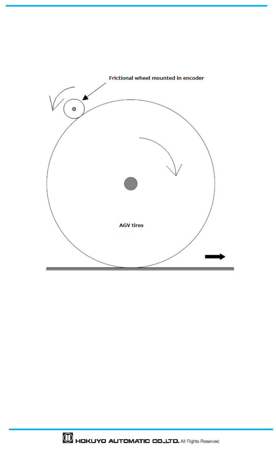
3.6.1 Pulse per cm travel generated by incremental encoders
When AGV travels, incremental encoder generates pulses due to the transmission ratio between AVG tires
and incremental encoder frictional wheel. Pulse count per cm depends on AGV's speed.
Figure 3-11 Calculation of pulse count per centimeter travel
AGV tire diameter: 40 cm
Frictional wheel diameter mounted in incremental encoder: 5 cm
Incremental encoder pulse number per revolution: 1000 pulse
AGV tire circumference = Diameter × Circumference ratio = 40 cm × 3.14 = 125.6 cm
AGV tire's one rotation is equivalent to 8 rotations of frictional wheel. This equals to the 8,000 pulses of
incremental encoder.
From above, incremental encoder pulse count per cm is obtained as
8,000/125.6 = 63.7
While setting encoder parameters (Encoder Pulse1 and Encoder Pulse2) in UAM project Designer, set
the encoder pulse count after rounding the calculated value to nearest whole number (64 in this case)
25
Document No: C-61-00003-3
In the explanation above, the transfer method of the rotation was based on the frictional wheel. Same
method can be applied for other cases to estimate the pulse count generated for one rotation of the
wheel.
3.6.2 Recommend incremental encoder specification
・ Phase setting 90° dual channel rotary encoder
・ Power supply: DC 24V
・ Output : Complementary output
・ Protective class : IP 54 or more
・ Output cable : Twist pair/ shield cable
・ Maximum pulse frequency : 100 kHz
・
Minimum pulse frequency : 50 pulse/cm
3.6.3 Tolerances allowed for encoder
When AGV travels in a forward direction, speed input through the two incremental encoders will be same
as the original pulse frequency. However, there are cases when two speed input values may differ, such as
while cornering and due to AGV tire exhaustion. The difference between two input speeds should not exceed
the error tolerance for more than a fixed period of time. Set the error tolerance in the range of 0 to 80%.
Of the two speeds, the larger value will be considered for vehicles speed calculation. When permitted error
tolerance exceeds the fixed period OSSD will go to OFF state. Tolerance period differs according to the
vehicle speed as shown in table 3-3.
User should verify the proper area switching through encoder inputs.
Always use 2 units of incremental encoder. It is not possible to detect
the failure of
incremental encoder or abnormal travel of the vehicle with single unit.
・
Use separate sets of cable to connect outputs from incremental encoder 1 and 2 to the
respective encoder input terminals of UAM.
Separate the power supply cables and power source of each incremental encoder.
Output
pairs of Encoder connection should match the input pair of UAM.
Do not wire other power lines parallel to encoder and UAM or wire in the same duct. There
is a possibility of noise disturbance.
Document No: C-61-00003-3
26
Table 3-3 Relation between AVG speed and tolerance
AGV speed v (cm/s) Tolerance
-9≦ v ≦+9 Infinity
-30<v<-9 or 9<v<30 60s
v≦-30 or +30≦v 20s
v<-9 or +9<v
(T
wo
encoders with different rotati
n
g
direction)
0.3s
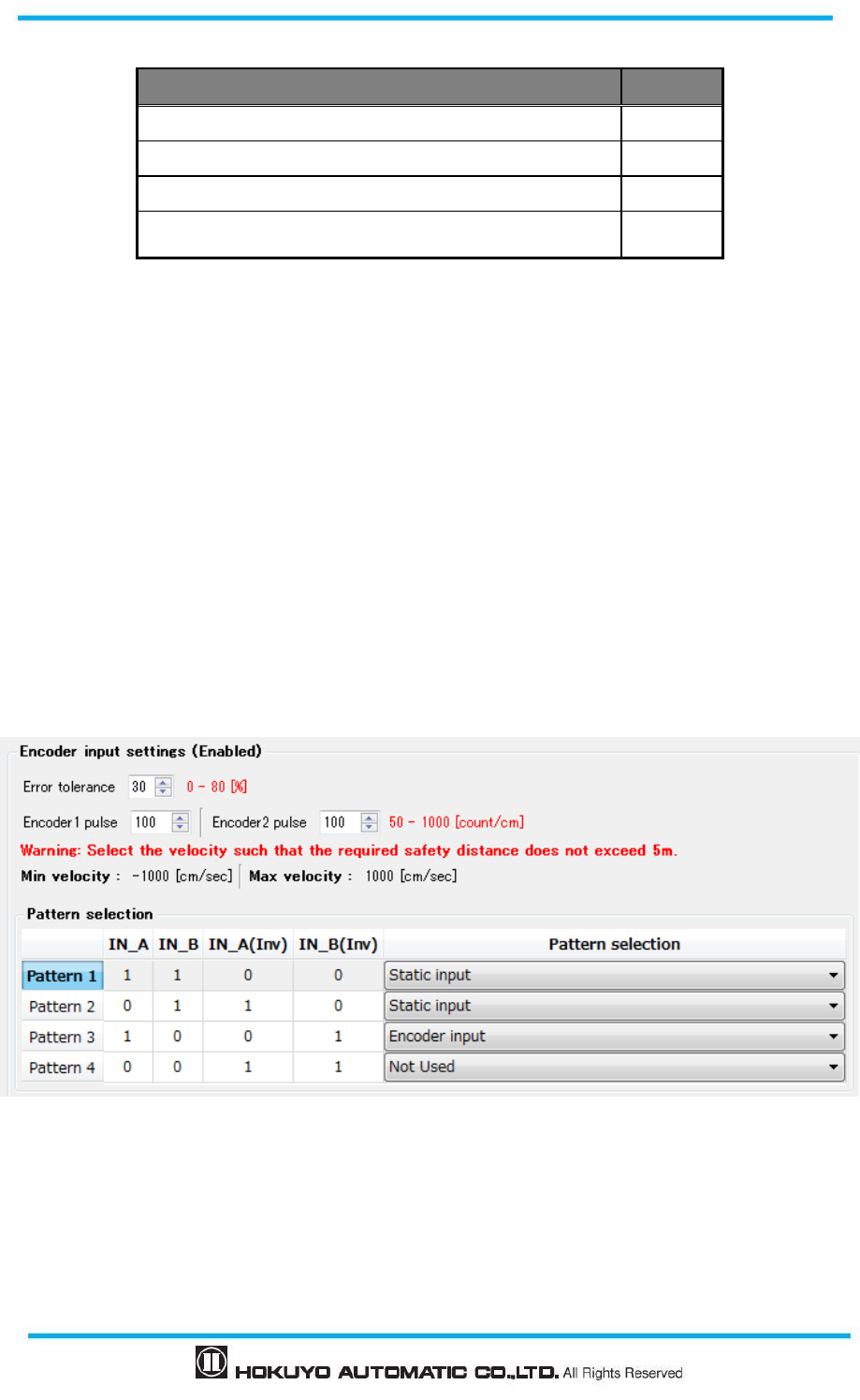
3.6.4 Area switching by encoder input
When encoder setting is enabled, four patterns can be selected from two available external inputs. For
each pattern, select either to use as static input or the encoder input or not in use. It is necessary to select at
least one pattern for encoder input.
For encoder input pattern maximum 32 sets of area switching can be performed for the range of speed.
Encoder setting is enabled by the of UAM project designer, as shown in Figure 3-12. For using the UAM
Project Designer refer to chapter 7.
Set the error tolerance and encoder pulse count for per cm travel.
The minimum and maximum speed is automatically calculated from the pulse count and maximum pulse
frequency (100 kHz). Next, select the input patterns to use as static input or for the encoder input or not used.
Figure 3-12 shows an example of encoder input setting. In this example, pattern 1 and pattern 2 are used as
static input, pattern 3 is used as encoder input and pattern 4 is not used.
Figure 3-12 Example of pattern switching through encoder input
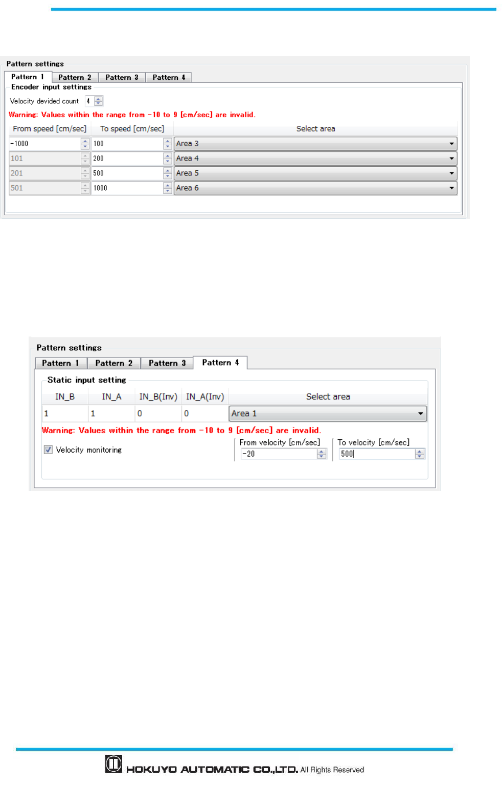
Next, divide the speed into number of ranges and specify the area number for each range. An example is
shown below (maximum 32 sets of area can be set). Same area cannot be specified for different speed within
a pattern. However it is possible to select same area for a different pattern.
Figure 3-13(a) shows the example of encoder input setting.
27
Document No: C-61-00003-3
In this example, speed is divided into 4 ranges and each speed range is assigned Area 3 to Area 6.
Figure 3-13 (a) Example of encoder input setting
When the pattern is set for static input, area number and encoder speed monitoring are configured. Speed
monitoring monitors the speed of the encoder and if it exceeds the limit OSSD will be switched to OFF state.
Figure 3-13(b) shows the example of static input setting. In this example, Area1 is assigned to the input
pattern and speed monitoring is enabled with the monitoring speed range -20 to 500cm/sec.
Figure 3-13 (b) Example of static input setting
3.7 OSSD
OSSD is safety-related signal. When humans or objects are detected in the protection zone, the OSSD
signal will switch to OFF state from ON-state. OSSD signal has the self- diagnostic function which tests the
signal periodically by switching it to OFF state for a brief period. Signal is continuously switched to
OFF-state when an error is detected during the diagnostic.
Output states of OSSD1 and OSSD2 signal are identical. Both signals should be connected to the safety
related machines or control system to fulfill the required safety level. If OSSD3 and OSSD4 are used they
must be connected in the same manner.
Document No: C-61-00003-3
28
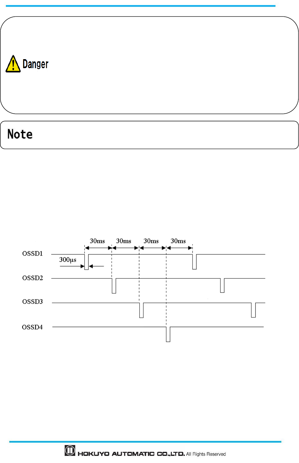
3.7.1 Self-diagnostic function of OSSD
Self-diagnostic is a function to detect the malfunction in the output circuit by switching OFF the OSSD1
to OSSD4 for an interval of 300µs. Therefore, safety-relay or power converter used must not response to this
diagnostic function. Figure 3-14 below shows the timing chart of the self diagnostic function of the OSSD
during dual protection mode.
Figure 3-14 Timing chart of the OSSD’s self-diagnostic function
In single protection mode, self-diagnostic function is done for OSSD1 and OSSD2 signals only.
3.7.2 Lockout state
When an error is detected by the self-diagnostic function and UAM cannot operate normally it will
switch to lockout state. During the lockout state, OSSD1/2, OSSD3/4, WARNING1, WARNING2 will
switch to OFF-state. After removing the error, UAM can be reset by restoring the power to release from the
lockout state.
When OSSD is at ON state, the signal is 24V and the signal is 0V during OFF state.
OSSD is a safety related signal and should be connected directly to the relay or
device that switches the machine or vehicle under control.
Sufficient time for the machine or vehicle must be allocated to stop
when configuring
the response time of OSSD.
Both the OSSD1 and OSSD2 outputs should be connected to the safety related
machines or control system. If OSSD3 and OSSD4 are used they must be connected
similarly.
User must verify the configuration before actual operation.
29
Document No: C-61-00003-3
3.7.3 Interlock function
Interlock is a function to prevent automatic restart of the OSSD signal switching from OFF-state to
ON-state. Automatic restart, manual restart and manual start interlock functions are configurable using the
UAM Project Designer.
3.7.3.1 Automatic restart
UAM will restart automatically when interlock function is disabled or only the start interlock function is
enabled. When obstacle from the protection zone is removed, OSSD signals switch from OFF-state to
ON-state automatically. OSSD response times for ON and OFF states are configurable (See section 3.12).
However, if UAM is in the lockout state due to error, OSSDs will remain in OFF-state even if the interlock
function is disabled.
Figure 3-15 Timing chart of automatic restart
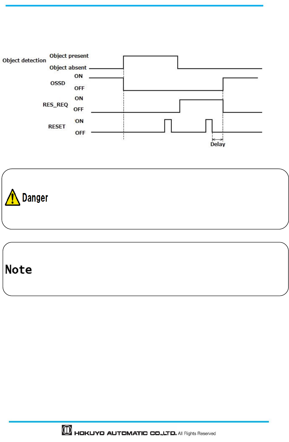
3.7.3.2 Manual restart (Interlock enabled)
UAM operates in manual restart mode when interlock function is set to manual mode. The OSSD signal
switches from ON-state to OFF-state, if UAM detects any obstacle within the protection zone or detects any
system error. In this mode, even if the detected obstacles or system error is removed, OSSD signals will
remain in OFF-state. An external reset input signal is required to release the interlock which allows the UAM
to switch to normal operation.
UAM will resume normal operation only after confirming the reset signal (RESET). The duration of the
reset signal should be more than 500ms. Figure 3-16 shows the timing chart of the manual restart. After reset
signal is confirmed, the OSSD signal will switch to ON-state after the lapse of the configured delay time. . If
In automatic restart configuration OSSD will automatically switch
to ON state after the
object is removed. Confirm the safety while removing the object.
Configured response time should be sufficient for the machine or AGV to stop safely.
Document No: C-61-00003-3
30
OSSD's OFF-state is due to an internal fault, it will remain in OFF-state even when reset signal is provided.
Reset delay is configurable in the range of 1s to 6s.
Figure 3-16Timing chart of manual restart
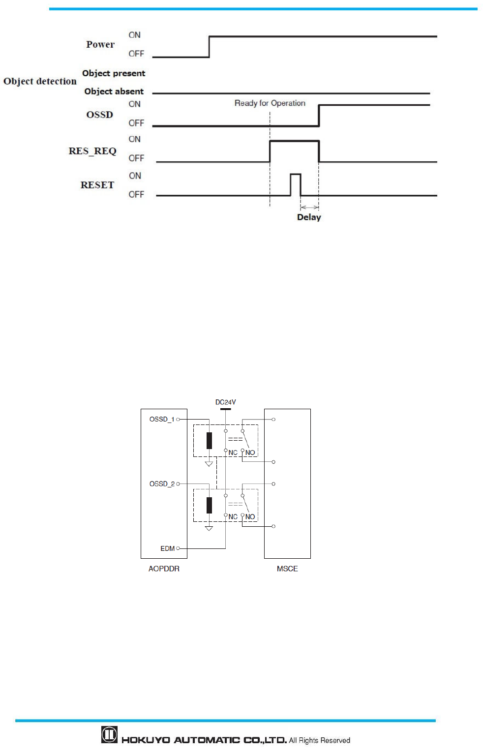
3.7.3.3 Manual start (Interlock enabled)
Start interlock is a function which keeps the OSSD in OFF-state during the start-up until an external
reset input is applied. Start interlock setting has only manual mode. The RES_REQ signal switches to
ON-state after the UAM completes initial routines and ready to accept the RESET input. When RESET input
is applied, OSSD will switch to ON state if no object is detected in the protection zone. The duration of the
reset input should be more than 500ms. Figure 3-17 shows the sequence of start interlock. Delay can be
configured in the range of 1s to 6s.
User should verify that the detected obstacle is safely removed
before resetting the
UAM.
If restart interlock function is used to restart the machine, the reset switch should
be
mounted away from the protection zone.
Falling to comply with the above could lead to critical injury or death.
Even after the object is removed from the protection zone, if the OSSD still
remains in
OFF-state, check the error code and suggested solution (Refer to Chapter 9)
Duration of
reset input should not exceed 30s; otherwise it will be detected as hardware
malfunction.
31
Document No: C-61-00003-3
Figure 3-17 Manual start sequence
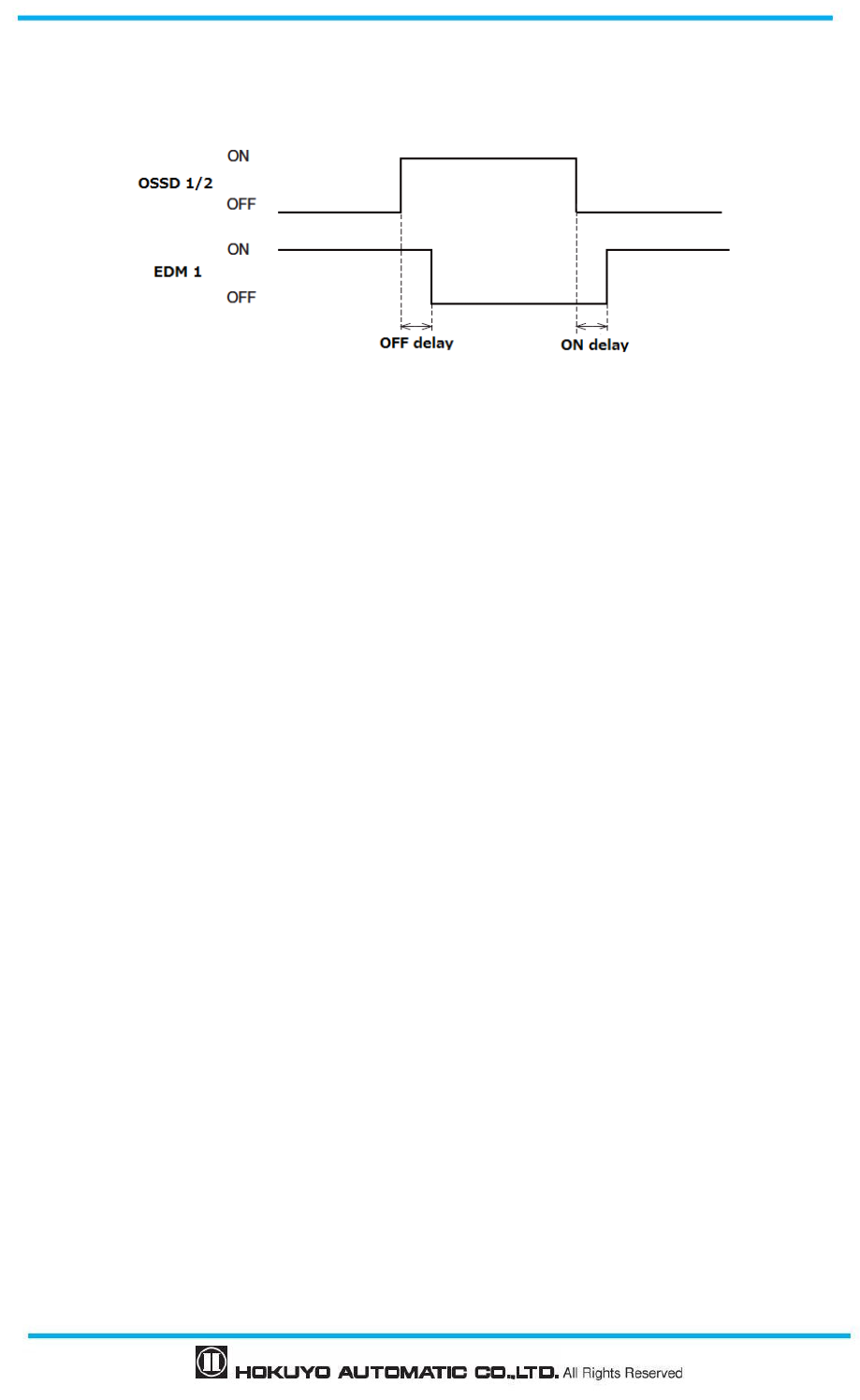
3.8 External device monitoring (EDM) function
EDM is a function that monitors the state of the input signal from the controlled machine or automated
guided vehicle (AGV). EDM is configured using the UAM project designer. When EDM function is enabled,
any fault detected in EDM signal will switch the OSSD signal to OFF-state. Logic of EDM signal should be
always inverse of the OSSD signal. EDM input signal ON/OFF delay is configurable to match the user’s
system. Figure 3-18 and 3-19 below shows the EDM circuit and EDM timing chart respectively.
Figure 3-18 EDM circuit
Document No: C-61-00003-3
32
Figure 3-19 EDM timing chart
In dual protection mode, EDM2 circuit and timing chart for OSSD3 and OSSD4 are same as above.
3.9 Muting function
Muting function temporarily suspends the safety function in the configured zone of UAM when the
specified conditions are fulfilled. In the muting state OSSD remains in the ON-state even when an object is
detected in the configured muting zone. Two independent hard wired input signals are provided to start and
end the muting function. Muting zone is configured using the UAM project designer (Refer to section 7.9.1).
When muting inputs fulfill the muting start conditions, UAM will suspend the safety function within 60ms
and resume the safety function if they fulfill the muting stop conditions.
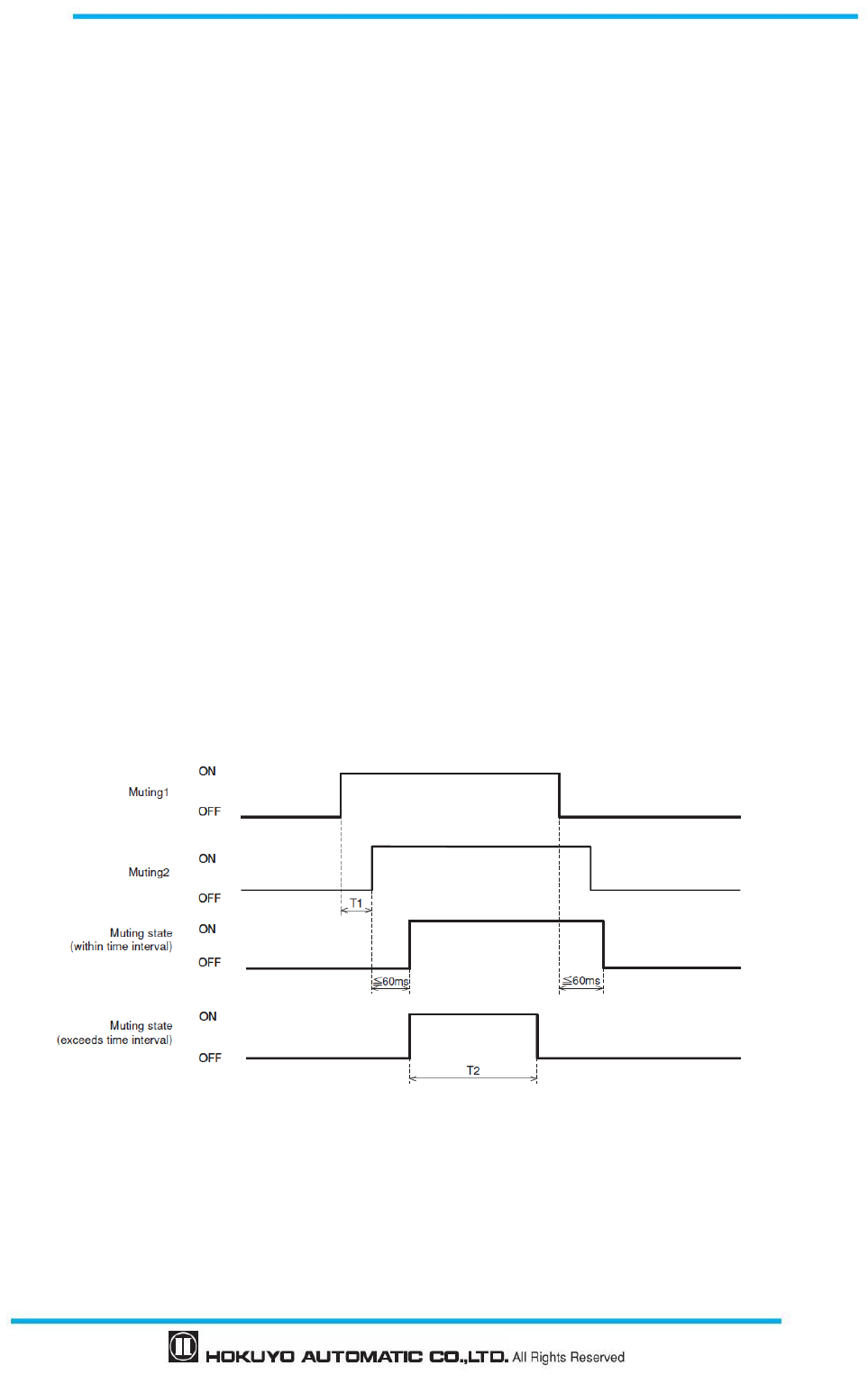
3.9.1 Muting start condition
Muting function will start when the following conditions are fulfilled:
a) There are no objects in the protection zone and the OSSD is in ON-state.
b) The two independent hard wired muting input signals are switched to ON state in the predefined
sequence within the pre-set time interval. However, the switching interval between two input signals
should not be 0 (Refer to figure 3-20).
The following configurations are necessary for the muting function. User can configure these by using the
UAM project designer.
Muting inputs sequence
▶ Muting 1 Muting 2
▶ Muting 2 Muting 1
Time interval between two inputs (T1)
▶ 1second
▶ 3seconds
▶ 5seconds
33
Document No: C-61-00003-3
▶ 10seconds
When using muting function in dual protection mode, Muting 3 and Muting 4 are configured in the similar
way.
3.9.2 Muting stop condition
Muting function will stop when any one of the condition below is fulfilled:
a) One of the muting inputs switches to OFF-state.
b) When the predefined (preset) maximum muting time T2 exceeds (1 minute and above) (Figure 3-20).
c) Objects are detected in the protection zone which is not covered by the muting zone.
d) Error is detected by the self-diagnostics function.
e) During muting state when the area is switched to other area.
Figure 3-20 shows the muting sequence.
Maximum muting period (T2)
Maximum muting period can be selected from one of these values
▶ 1 minute
▶ 6 minutes
▶ 12 minutes
▶ Unlimited
When using the muting function in dual protection mode, Muting 3 and Muting 4 are configured in the
similar way. Same applies for muting input sequence, time interval between inputs and maximum muting
period.
Figure 3-20 Muting sequence
Document No: C-61-00003-3
34
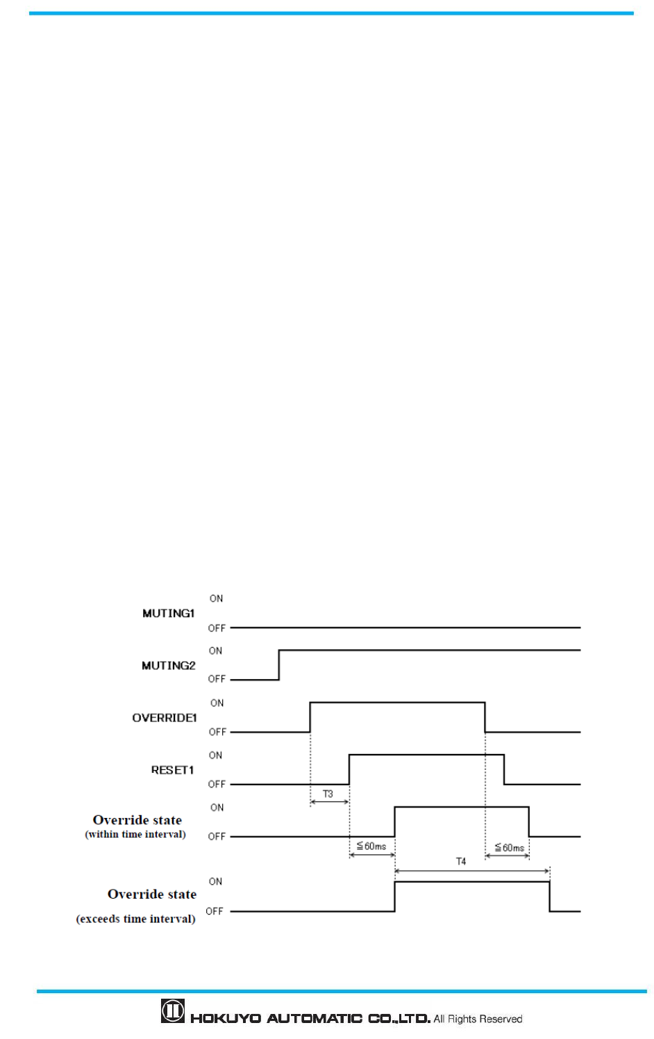
3.9.3 Muting override function
Muting override is a function to recover UAM when the OSSD is switched to OFF state due to muting
related errors by temporarily suspending the safety function. Override function is active when the override
input (OVERRIDE 1/2) and the reset input (RESET 1/2) are switched in a sequence. Figure 3-21 shows the
override sequence.
Override start conditions
▶ At least one of the muting inputs is in ON-state.
▶ Object is present in the protection zone.
▶ Time interval between override input and reset input is within 0.03s to 1s (T3).
Override stop conditions
▶ Both muting inputs are in OFF-state.
▶ Override input or reset input is in OFF-state.
▶ When predefined maximum override time T4 exceeds.
▶ Error is detected by self-diagnostic function of the UAM.
▶ During override state when area is switched to the other area.
Maximum override period (T4)
Maximum override period can be selected from one of these values
▶ 1 minute
▶ 6 minutes
▶ 12 minutes
Figure 3-21 Override Sequence
35
Document No: C-61-00003-3
When using muting override in dual protection mode, Muting 3, Muting 4, Override input 2 and Reset
input 2 are configured in the similar way.
3.10 Reference monitoring function
Reference monitoring is a function to monitor the displacement of the UAM or the structure used as
reference boundary.
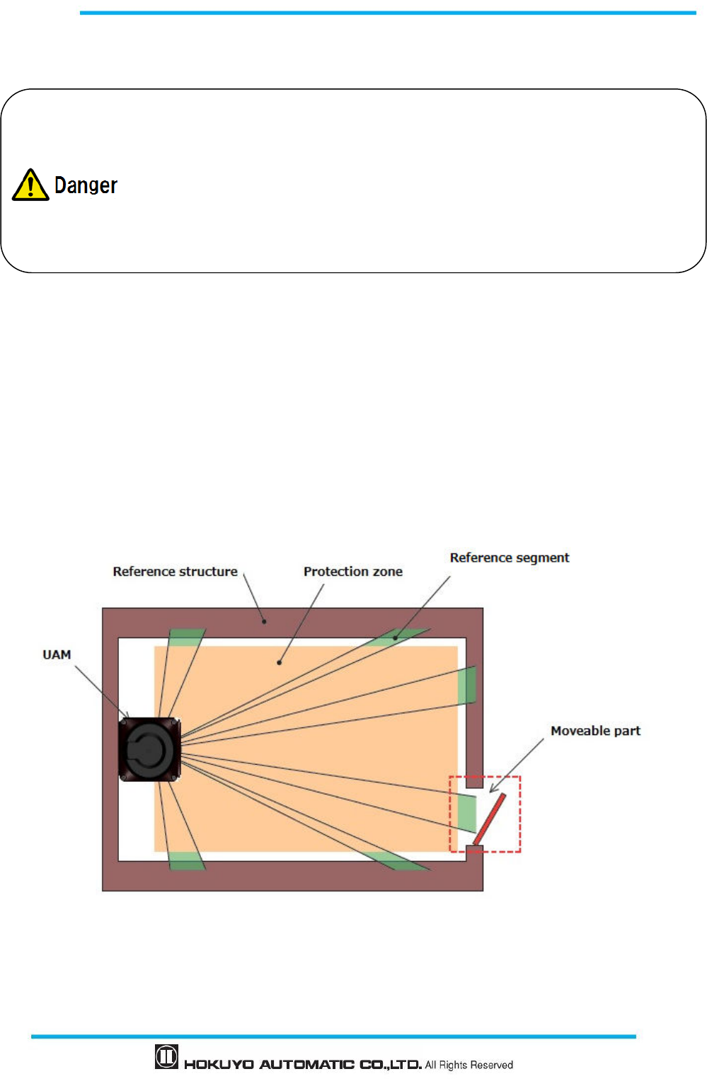
3.10.1 Area protection
An example of reference monitor function used for area protection is shown in figure 3-22. If reference
segments are configured on moveable objects (example: door) the OSSD will switch to OFF-state when the
door position is changed.
Figure 3-22 Top view of the area protection using reference monitor function
When muting function is enabled, user must ensure the safety of the protection zone.
Before using the muting function, user must perform risk assessment.
A qualified person should configure the
appropriate muting period according to the
requirement of the application. It is the user’
s responsibility to properly perform the risk
assessment when configuring muting period to unlimited.
Failing to comply with the above could lead to critical injury or death.
Document No: C-61-00003-3
36
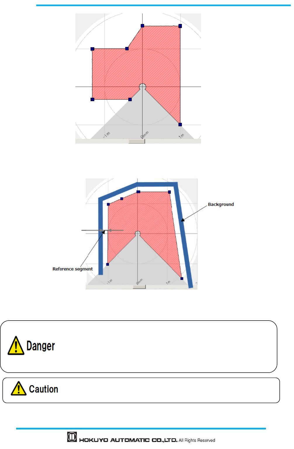
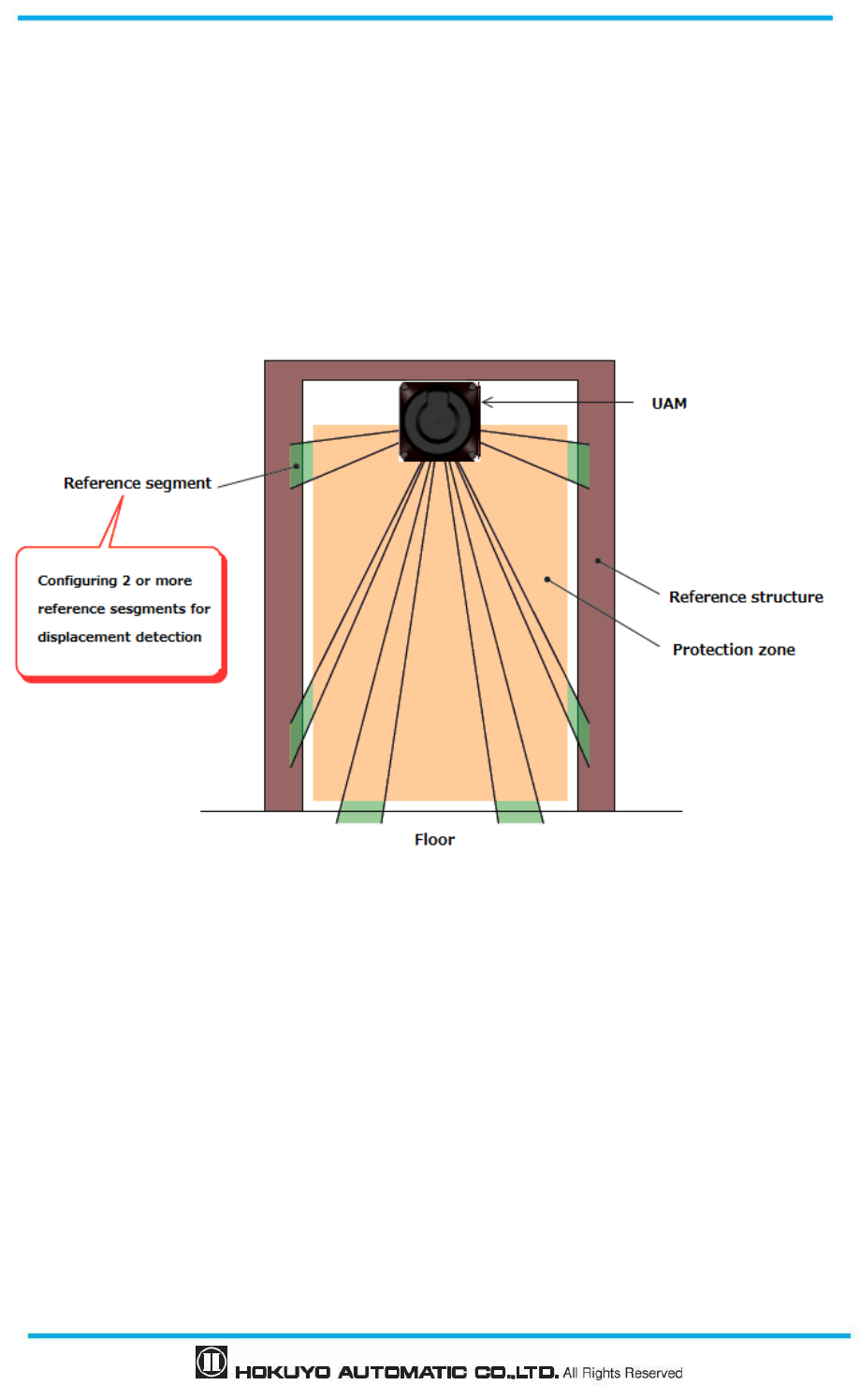
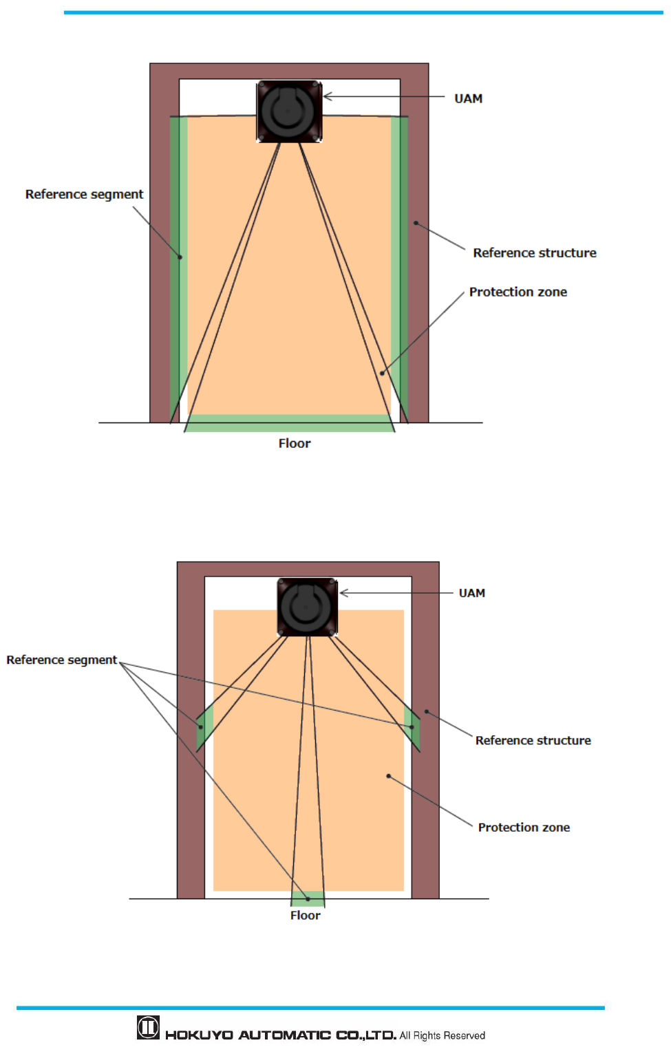
3.10.2 Access protection
An example of reference monitor function used for access protection is shown in figure 3-23(a), (b).
Reference segments should be configured on each surface for displacement detection. Reference segments
should be configured such that displacement can be easily detected. The OSSD will switch to OFF-state
when access penetration is detected, and also if the distance between UAM and the reference structure
changes. This function is compulsory for vertical applications.
Figure 3-23 (a) Front view of the access detection using reference monitor function
37
Document No: C-61-00003-3
Figure 3-23 (b) Front view of the access detection using reference monitor function
Figure 3-23(c) Incorrect configuration of reference segment
Document No: C-61-00003-3
38
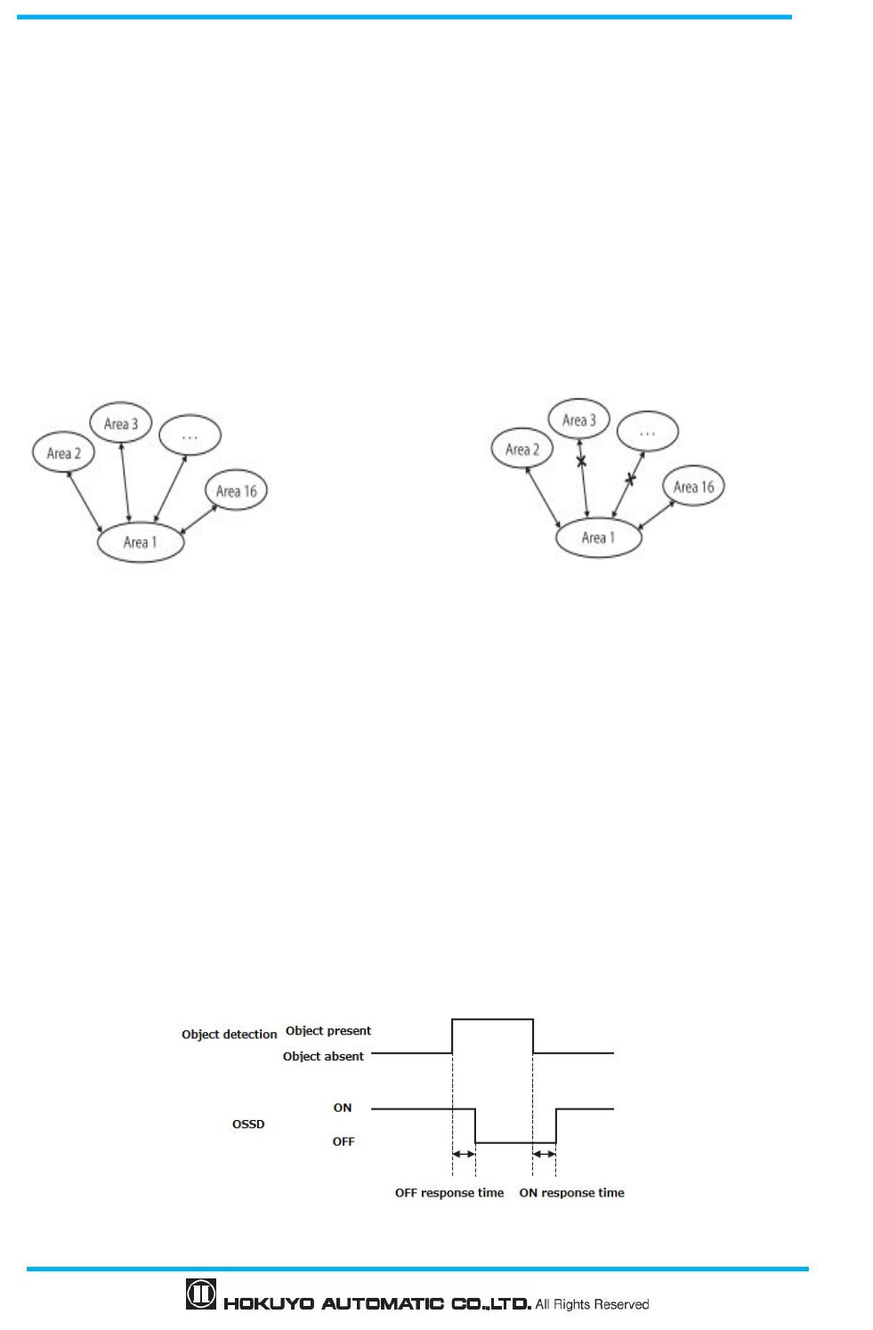
3.11 Area sequence function
Area sequence is a function to monitor sequences of area switching. When this function is activated,
OSSD signal will switch to OFF-state if the switching pattern is other than the configured sequence. This
function prevents the machine to operate with random protection zone.
From each area, switching selection to maximum 31 other areas is possible when configuring the area
sequence. And, it is necessary to specify 1 or more areas to avoid error.
<Area switching sequence>
When area sequence is disabled, UAM can switch from an area to any other areas (Figure 3-24(a) whereas
it can only switch to specified areas if area sequence is enabled. (Figure 3-24(b)).
Area sequence function is recommended for control systems where switching area sequences can be
configured.
Figure 3-24(a) Operation without area sequence Figure 3-24(b) Operation with area sequence
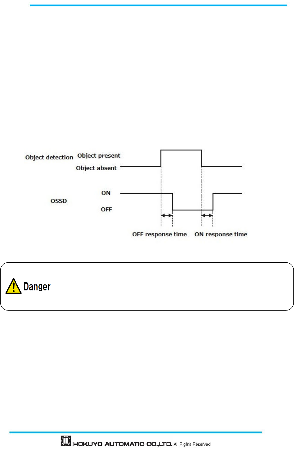
3.12 Response time
Response times of OSSD signal (Figure 3-25), OFF response time and ON response time (default
270ms) are configurable individually for each area using the UAM project designer. Response time of the
Warning 1 and Warning 2 will be same as the OSSD response time. Table 3-4 shows the possible
configurable values. In the dual protection mode, it is possible to set a separate response time for each
protection area.
When longer response time is configured, the stability of UAM can be increased. However, longer
response time requires longer safety distance. (Refer to chapter 4). User must perform risk assessment before
configuring the response time. Addition of maximum 1 cycle (30ms) has to be taken into account for the area
switching.
Figure 3-25 Response time
39
Document No: C-61-00003-3
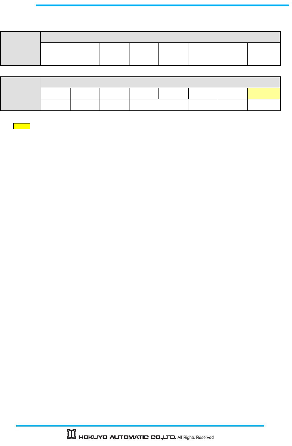
Table 3-4 Response time of UAM
OFF
Response time (ms)
60 90 120 150 180 210 240 270
300 330 360 390 420 450 480 510
ON
Response time (ms)
270
300 330 360 390 420 450 480 510
* Default value
* Default value of OFF response time varies depending on the selected application when creating a “New”
project. See Table 4-11 for the details.
* Minimum configurable response time in Master/Slave mode is 120ms for OFF and 300ms for ON.
3.13 Other outputs
UAM consist of 6 non-safety outputs, WARNING1, WARNING2, MUT_OUT1, MUT_OUT2 and
RES_REQ1 and RES_REQ2. WARNING1/OSSD3, WARNING2/OSSD4, RES_REQ1/ MUT_OUT1 and
RES_REQ2/ MUT_OUT2
are configurable outputs that share the same terminal. When the functions are
selected using UAM project designer, outputs are configured automatically.
3. 13.1 Warning output 1 (WARNING 1)
This signal will switch to OFF-state when an obstacle is detected in the configured warning zone 1.
3. 13.2 Warning output 2 (WARNING 2)
This signal will switch to OFF-state when an obstacle is detected in the configured warning zone 2.
3. 13.3 Muting output 1 (MUT_OUT 1)
MUT_OUT1 indicates the muting/override status of the protection zone 1. When the muting function is
activated, MUT_OUT1 will switch to ON-state. At the same time, number 37 is displayed on the 7-segment
LED. This signal should be used to indicate that protection zone 1 is in muting state or override state.
3. 13.4 Muting output 2 (MUT_OUT 2)
MUT_OUT2 indicates the muting/override status of the protection zone 2.When the muting function is
activated, MUT_OU2 will switch to ON-state. At the same time, number 38 is displayed on the 7-segment
LED. This signal should be used to indicate that protection zone 2 is in muting state or override state.
When both protection zone 1 and protection zone 2 are in muting or override state, number 39 is displayed
on the 7-segment LED.
Document No: C-61-00003-3
40
3. 13.5 Reset Request 1 (RES _ REQ1)
This signal will switch to ON-state when the protection zone 1 of the UAM is ready to receive reset
signal.
3.13.6 Reset Request 2 (RES _ REQ2)
This signal will switch to ON-state when the protection zone 2 of the UAM is ready to receive reset
signal.
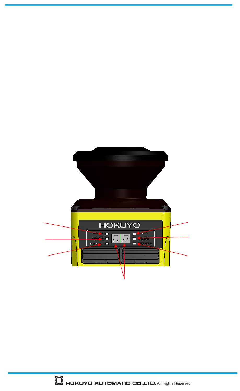
3.14 Information indicator
LEDs and 7-segment display indicate the UAM status. These indicators are located in front of UAM.
Figure 3-26 shows the information indicators of the UAM.
Figure 3-26 Indicator lamp
7-Segment display
OSSD 1/2 indicator
Warning 1 indicator
Interlock 1 indicator
OSSD 3/4 indicator
Warning 2 indicator
Interlock 2 indicator
41
Document No: C-61-00003-3
3.14.1 LED
LED indicators and their descriptions are shown in Table 3-5.
Table 3-5 Description of indicator LEDs
LED Color Description
OSSD 1/2 Green/Red
Green LED when OSSD 1/2 signal is in ON state,
Red LED when OSSD 1/2 signal OFF state
OSSD 3/4 Green/Red
Green LED when OSSD 3/4 signal is in ON state,
Red LED when OSSD 3/4 signal OFF state
Green LED when OSSD 3/4 signal is not in use
WARNING 1 Orange
LED ON when Warning 1 signal is in OFF state
LED OFF when Warning 1 signal is not in use
WARNING 2 Orange
LED ON when Warning 2 signal is in OFF state
LED OFF when Warning 2 signal is not in use
Interlock 1
Orange
LED ON when OSSD 1/ 2 is in interlock state
Interlock
2
Orange
LED ON when OSSD 3/ 4 is in interlock state
3.14.2 7-Segment display
Table 3-6 shows the descriptions of the numbers shown 7 segment display of UAM.
Numbers can be displayed upside-down by enabling the 7-segment display function on the configuration
software “UAM Project Designer”. This will help to read the numbers with ease when the device has to be
inverted for the mounting. Dots on the 7-segment will illuminate when the upside-down display function is
active.
Table 3-6 Description of numbers displayed on 7-segment
Display number Details
00 Sensor is initializing
01 – 32 Selected Area 1 to 32
33 Setting mode
34 Interlock state (Protection zone 1)
35 Interlock state (Protection zone 2)
36 Interlock state (Both protection zone 1and 2)
37 Muting or Override state (Protection zone 1)
38 Muting or Override state (Protection zone 2)
39 Muting or Override state (Both protection zone 1 and 2)
40 Laser Off mode
F2 SD card is detected with correct configuration file
F3 Configuring the sensor from the SD card information
F4 Configuring from the SD card is successful. Remove the SD
card to complete the process.
F5 SD card process is complete. Sensor is going to restart.
Fb Reset of IP address is complete. Sensor is going to restart.
Note: Display numbers other than the above are error state. For details refer to table 9-2 for details ( page 133)
.

Document No: C-61-00003-3
42
3.15 Ethernet communication
Measurement data of UAM can be obtained from the Ethernet communication. Water proof Ethernet
connector is located at the back of UAM. To connect sensor with PC use an Optional Ethernet cable
(UAM-ENET).
UAM is compatible with SCIP2.2 communication protocol standard. Refer to UAM-05LP communication
specification (C-64-00012).
3.15.1 Ethernet Setting
● Default setting
Factory default value is shown below.
IP address : 192.168.0.10
Default gateway : 192.168.0.1
Subnet mask : 255.255.255.0
Port number : 10940
● Changing the IP address
IP address can be changed by using UAM project Designer. Refer to section 7.13 and 7.9.1 for details.
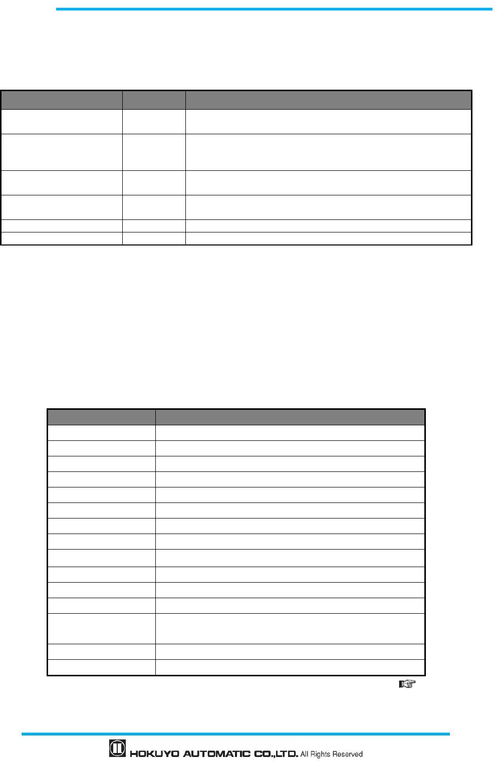
● IP address initialization
Ethernet settings can be set to factory default by using IP initialization switch.
<Initialization steps>
a) Prepare a thin strong pin for IP initialization process. IP initialization switch is located exactly below the
SD card Slot (Refer to figure 3-27)
b) When UAM is operating in normal state, press and hold the IP initialization switch for more than 3
seconds. After initialization process is complete 7-segment display status changes to “Fb”.
c) Sensor restarts with 7-segment display showing the status “00”.
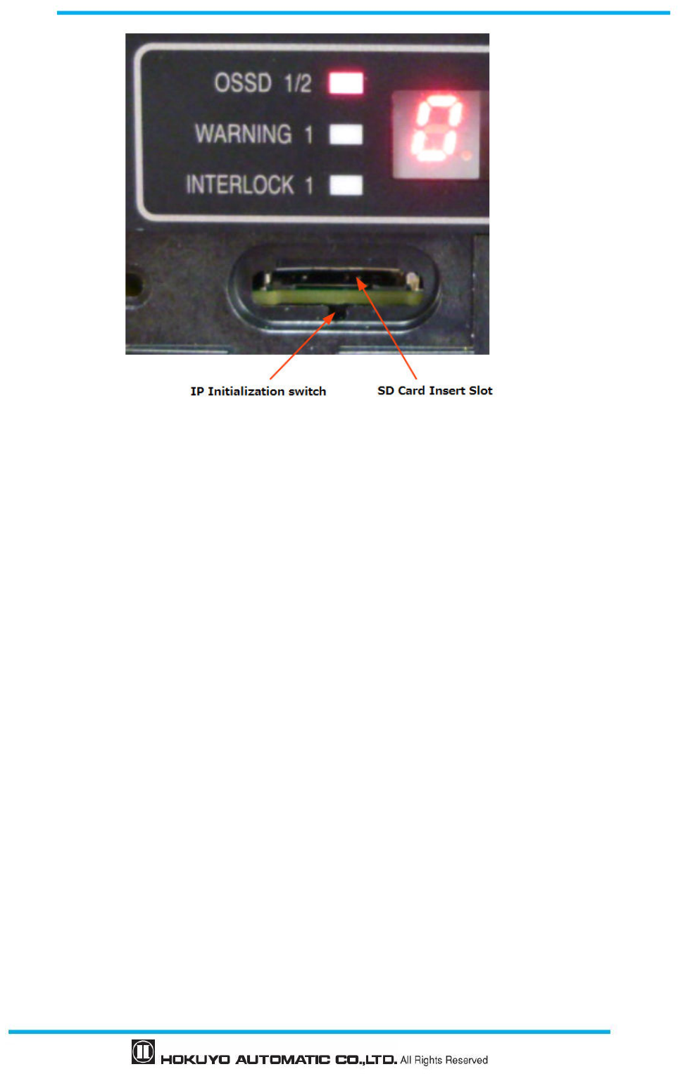
43
Document No: C-61-00003-3
Figure 3-27 IP initialization switch
3.16 Function to configure UAM by SD card
Configuration generated by UAM Project Designer can be saved in the SD card. It is possible to transfer
the setting directly from the SD Card to UAM without connecting to a PC. Recommended specification of
SD card is given below.
Create a project file with set the serial number and password of the UAM and save it on the SD card using
UAM Project Designer. When the SD card is inserted to the specified UAM, settings are automatically
transferred. It is possible to register multiple serial number and password in the SD card to simultaneously
configure multiple devices. Setting will not be transferred to the unspecified UAM or if the password
verification fails.
Specification of SD card
Type: Micro SD card, Micro SDHC card
Capacity: 16GB or less
3.17 Master-Slave Function
Maximum 4 units of UAM can be interconnected using RS-485 for Master/slave operation. One unit will
function as a master unit communicating with up to 3 units that function as slaves via safety communication
channel. Use the UAM Project Designer to configure the devices. UAM will report error if the number of
master and slave units is different than the configured settings.
Area switching of the slave unit is linked with the master unit while the slave units transmit the object
detection information to the master which controls the OSSD. It is also possible to use each slave unit’s
OSSD. Figure 3-28 shows the connection example.
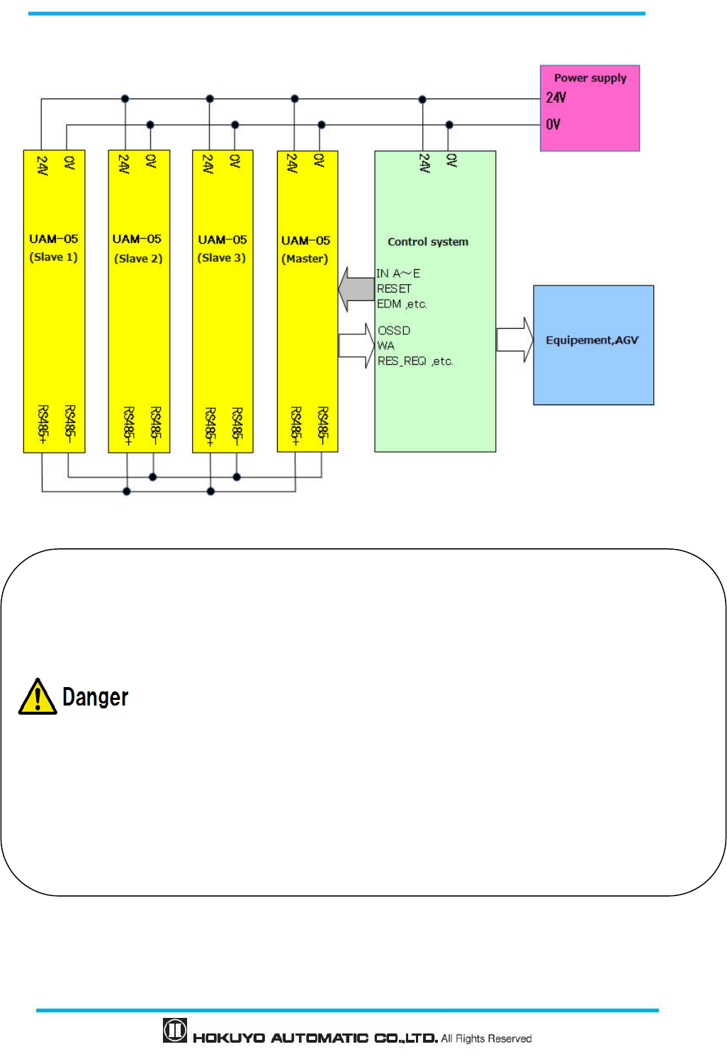
Document No: C-61-00003-3
44
Figure 3-28 Connection example (When OSSD of slaves are not in use)
Perform the risk assessment before using the master-slave function.
User should comply with all the following conditions when using the master-slave function.
1. There should be one device configured as master in the system.
2. Number of slave units connected in the system should not exceed the slave cont configured
in
the master unit..
3. Configuration of slave identity number should be in the order starting from 1 without being
overlapped.
4. Verify that each device is mounted at their intended location.
5. Verify that each device matches the intended configuration.
Interlock function is mandatory when using the master-slave function for safety operation.
Connecting RS485 lines to devices other than UAM, such as actuators, is not possible.
Do not exceed the cable length between the master and each slaves beyond 20m.
Failing to comply with the above could lead to critical injury or death.
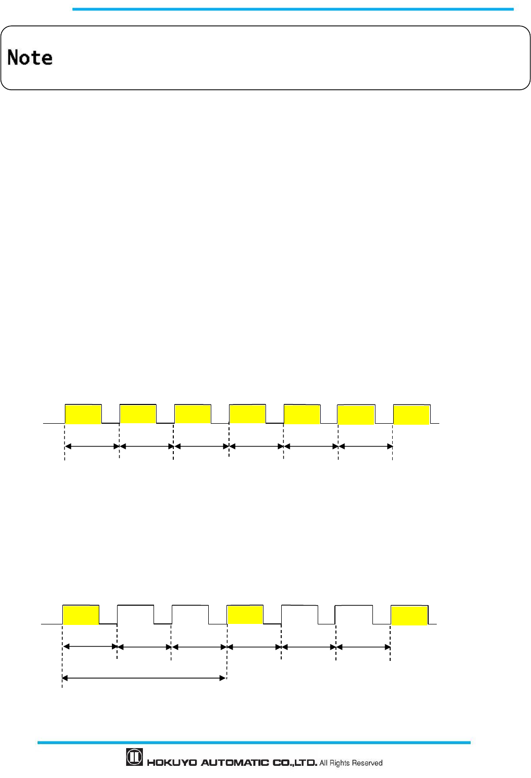
45
Document No: C-61-00003-3
3.18 Laser Off Mode
Laser off mode is a function to completely stop the laser emission in the measurement region in order to
prevent the interference to the surrounding equipment.
When this mode is enabled, Area1 is automatically assigned for laser off function. During the operation,
UAM will stop the laser emission and switch the OSSD to OFF state whenever the area is switched to Area1.
3.19 Scan Skip Function
Scan skip is a function to stop the laser emission for a specified number of scan cycles in the
measurement region in order to reduce the interference to the surrounding equipment.
When this function is enabled by specifying the skip count, UAM will operate by skipping the scan for
the number of cycles. During the skipping cycle the laser is switched off in the measurement region.
Configurable value for skip cycle is 0 ~ 3 count. Response time of UAM for the different settings is shown
in Table 3-7.
Figure 3-29 shows the operating concept when the scan skip is 0. In this configuration the scan skip
function is disabled and sensor operates normally.
Figure 3-29 Operation of UAM when scan skip count is 0
Figure 3-30 shows the operating concept when the scan skip is set to 2. In this configuration UAM will
skip the measurement for every 2 cycles in between the normal measurement cycles. Outputs states just
before the skipping cycle are retained during the skipping cycle.
Figure 3-30 Operation of UAM when scan skip count is 2
Configured active area count in master and slave units should be
the same except when using the
encoder input function.
Scanning area operation mode in master and slave units should be the same.
30ms
30ms
30ms 30ms 30ms 30ms
Scan 1
Scan 2
Scan 3
Scan 4
Scan 5
Scan 6
* Laser emitted cycle is shown in yellow
30ms 30ms 30ms 30ms 30ms
Scan 1
Scan 2
Scan 3
Scan 4
Scan 5
Scan 6
*Laser emitted cycle is shown in yellow
30ms
90ms
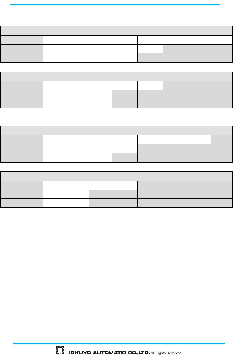
Document No: C-61-00003-3
46
Table 3-7 Response time for different scan skip settings
Master-Slave function disabled
Scan skip count
Off Response time (ms)
1 90 150 210 270 330 390 450 510
2 120 210 300 390 480
3 150 270 390 510
Scan skip count
On Response time (ms)
1 270 330 390 450 510
2 300 390 480
3 270 390 510
Master-Slave function enabled
Scan skip count
Off Response time (ms)
1 150 210 270 330 390 450 510
2 180 270 360 450
3 210 330 450
Scan skip count
On Response time (ms)
1 330 390 450 510
2 360 450
3 330 450
3.20 Optical Window Contamination Warning Function
This is a function to warn the optical window contamination by blinking the 7-segment display number
before contamination level reaches the maximum limit causing the OSSD signals to switch to OFF state.
Cleaning the optical window at the blinking stage will prevent the unnecessary stop due to contamination
error. No specific configuration is necessary to activate this function.
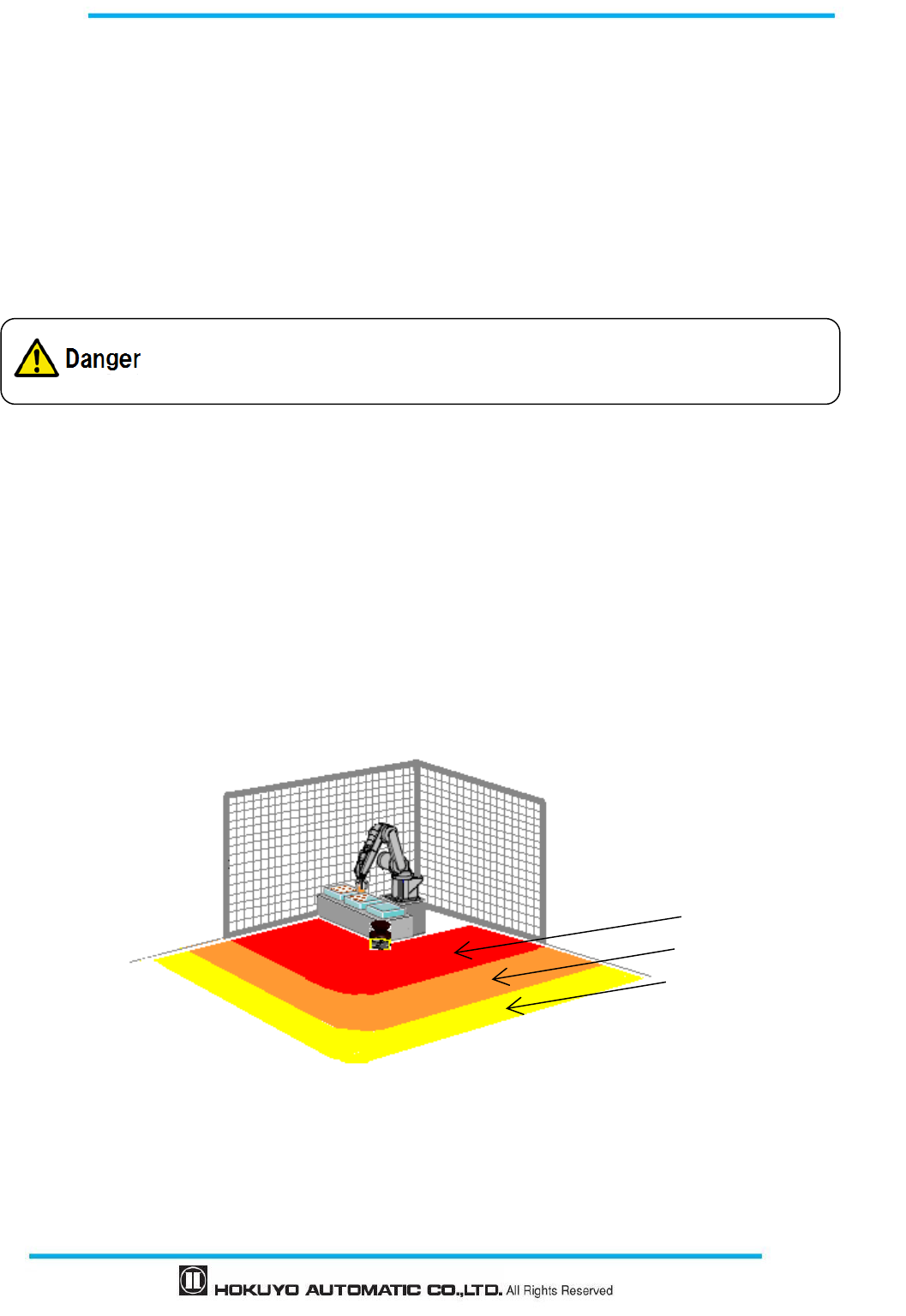
47
Document No: C-61-00003-3
4. Application examples of UAM
The section describes some application examples of UAM and safety distance calculation in the
respective application. When using the UAM as protective equipment, guidelines below should be taken into
account.
Hazard should be identified and risk assessment should be carried out.
UAM should not be used for finger protection.
Working environment should be within the specification of UAM.
Safety distance must be determined in accordance to ISO 13855 and IEC 61496-3.
4.1 Access protection (Horizontal application Stationary Protection zone 1)
In this kind of application, UAM is mounted horizontally to protect the hazardous area (Figure 4-1).
The protection zone is configured around the hazardous area to prevent the entry of human beings or object.
Warning zone 1 and Warning zone 2 are configured surrounding the protection zone. Warning zones are used
for alerting human beings or object from approaching the protection zone and preventing unnecessary stops
of the protected machine. Any objects or human beings detected in the protection zone will cause the OSSD
signal to switch to OFF-state from ON-state. Any objects and/or human beings detected in the warning zones
will cause the warning signal to switch from ON-state to OFF-state. The safety distance for this application
is shown in figure 4-2 and 4-3.
Figure 4-1 Example of access protection
Protection zone 1
Warning zone 1
Warning zone 2
Operating the UAM beyond its specification could lead to critical injury and death.
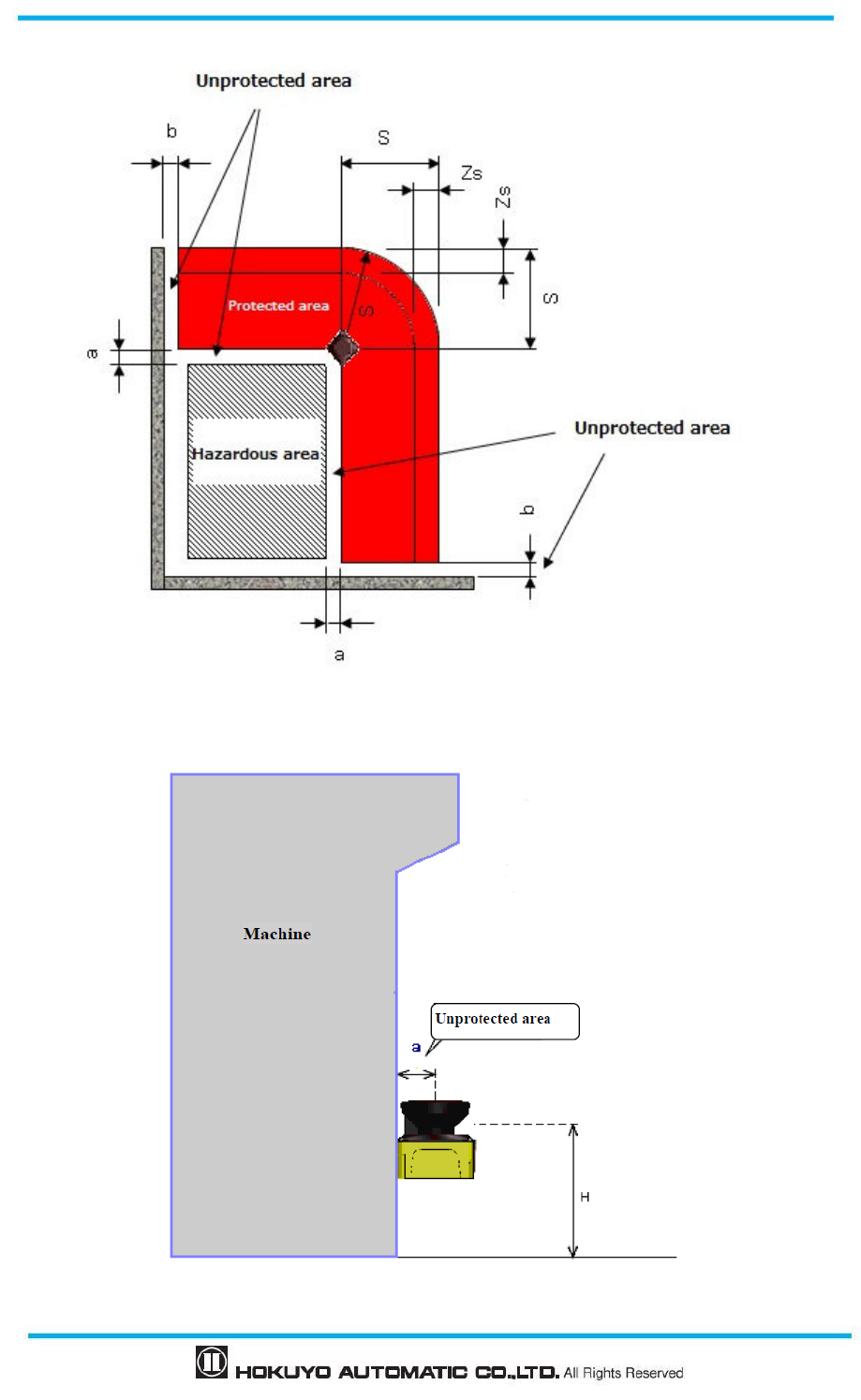
Document No: C-61-00003-3
48
Figure 4-2 Top view of the horizontal application
Figure 4-3 Side view of the application
49
Document No: C-61-00003-3
For safety distance calculation:
(
)
(
)
ssm
ZCTTKS +++×=
where:
S =
Safety distance (mm)
K =
Approach speed 1600 (mm/s)
T
m
=
Maximum stopping/run-down time of the machine or system (s)
T
s
=
Response time of UAM (s)
C =
1200-0.4×H
≧
850
H =
the height at which the protective field is mounted (mm)
1000
≧
H
≧
15× (d−50)
d =
Minimum detectable object width (mm)
Z
s
=
UAM tolerance distance (mm)
4.2 Access protection (Stationary Horizontal application with Dual
Protection zone)
In this kind of application, UAM is mounted horizontally to simultaneously protect two hazardous areas
(Figure 4-4). Protection zones are configured around the hazardous area to prevent the entry of human
beings or object. Warning zone cannot be configuration in dual protection mode. Any objects or human
beings detected in the protection zones will switch the respective OSSD signal to OFF state from ON-state.
In this configuration it is possible to protect two equipment using a single UAM.
User must ensure the distance
between the hazard zone edge and origin of the
protection zone “a” must be less than the minimum detectable width.
In application
where the value of “a” is greater than the minimum detectable width, additional
protective measures should be taken to preven
t penetration through this unprotected
area.
UAM should not be mounted higher than 300mm to prevent the possibility of
crawling beneath the detection plane.
For applications which require the UAM to be mounted higher tha
n 300mm,
additional measures should be taken to prevent intrusion beneath the detection plane.
If UAM is mounted in a public area, the height of the
detection plane should be
reduced to 200mm or to the height required by regulations of the local authority.
It is recommended to mark the floor of the protection zone.
Distance tolerance should be taken into account when configuring the safety distance.
Additional tolerance should be applied when UAM is used in the presence of
high reflective
background.
User should ensure that boundary or protective measures used are not included inside
the
protected zone. They will be detected as obstacles causing the OSSD to remain in OFF-state.
User should ensure the gap of 100mm between the
protection zone and the distance of the wall
“b” to prevent the detection by the sensor.
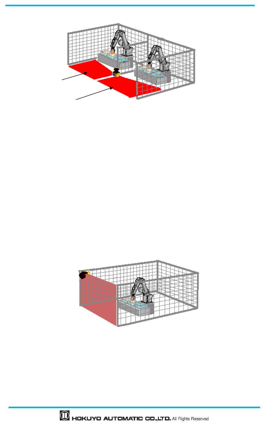
Document No: C-61-00003-3
50
The safety distance for this application is shown in figure 4-1.
Figure 4-4 Example Horizontal application of access protection (Dual protection zone)
4.3 Access protection (Vertical application- whole body detection)
UAM can be used as a protective shield by mounting it vertically (Figure 4-5). Application shown in the
figure is generally used in preventing the access to hazardous area. When an object or human enter the
passage, OSSD signal will switch from ON-state to OFF-state.
In this configuration, UAM detects objects or human beings in vertical plane. It is not possible to detect an
object or human being at the front or back side of the detection plane. Therefore, caution should be taken
while setting the distance between the detection plane and hazardous area. Configure the shortest response
time of UAM not exceeding 90ms. Always use reference monitoring function in such applications to detect
the displacement of fences and UAM which may expose the hazardous area. OSSD signal will switch to
OFF state when the position of reference is changed. The safety distance for this application is shown in
figure 4-6 and 4-7.
Figure 4-5 Example of access protection (Whole body detection)
Protection zone 1
Protection zone 2
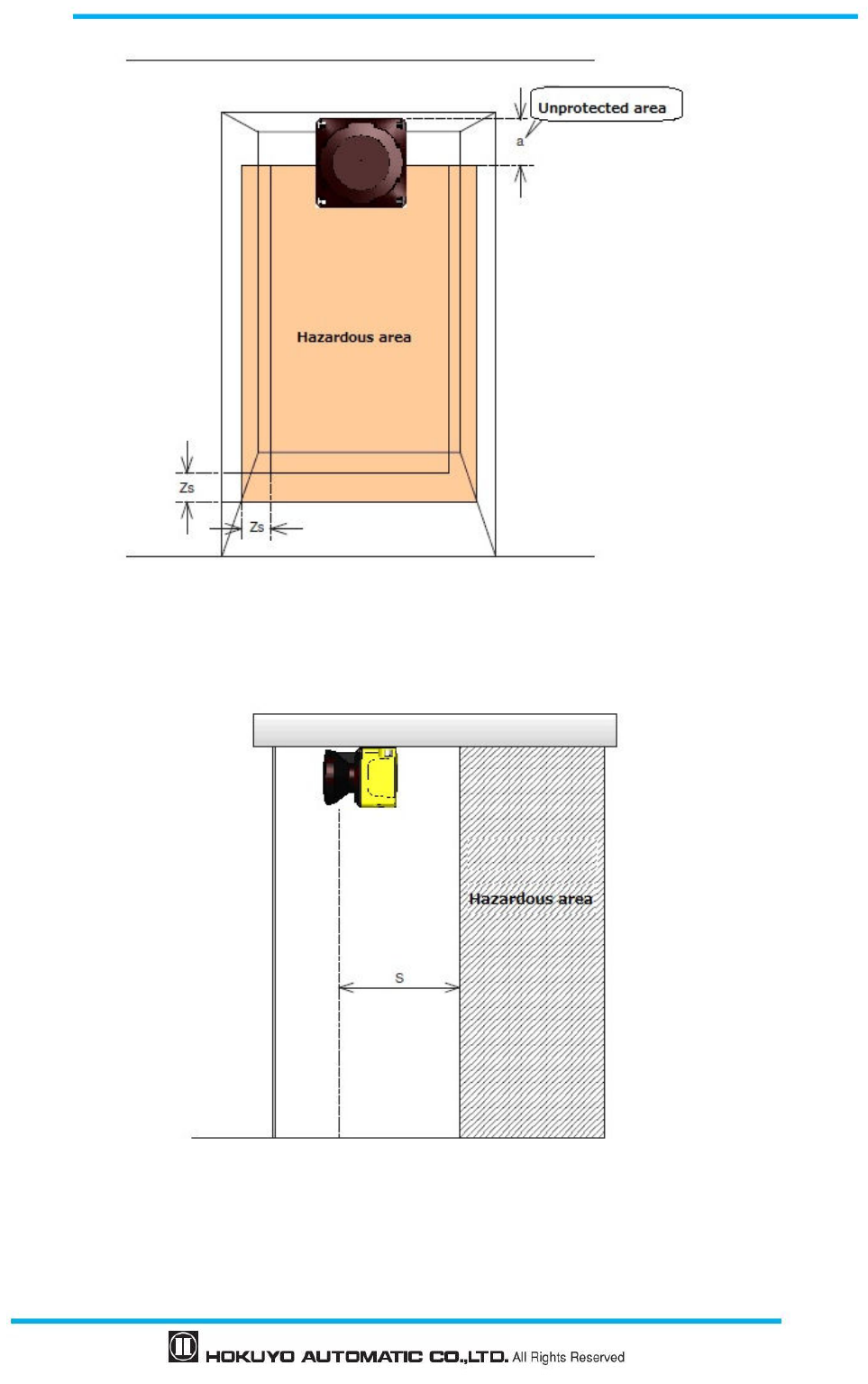
51
Document No: C-61-00003-3
Figure 4-6 Top view of access protection (Whole body detection)
Figure 4-7 Side view of access protection (Whole body detection)
For Safety distance calculation:
S=
==
=(K× ( Tm+
++
+Ts))+
++
+C
where:
Document No: C-61-00003-3
52
S = Safety distance (mm)
K = Approach speed 1600 (mm/s)
Tm = Maximum stopping/run-down time of the machine or system (s)
Ts = Response time of UAM (s)
C = Additional distance of 850mm by considering arm intrusion (mm)
4.4 Access protection (Vertical application Stationary)
Figure 4-8 shows an example to prevent the access when part of the body is approached near the
hazardous area. If objects or part of body enters such area, OSSD signal switches to OFF state from ON-state.
UAM detects an object or human being in vertical plane in such configuration. It is not possible to detect an
object or human being at the front or back side of the detection plane. Therefore, caution should be taken
while deciding the distance between approaching point and hazardous area. The width of protection zone
should be sufficient to protect the hazardous area. Always use reference monitor function in such
applications to detect the displacement of fences and UAM which may expose the hazardous area. OSSD
signal will switch to OFF state when the position of reference is changed. The safety distance for this
application is shown in figure 4-8 and 4-9. Refer to section 7 for configuring the protection zone.
User should ensure that the width of unprotected zone “a” is smaller than the
minimum detectable width. If the value of “a” is greater than minimum detectable
width, additional protective measures should be taken to prevent the penetration
through this unprotected zone.
In the access protection application where the angle of approach exceeds ±30º,
“Reference monitoring” function should be used with 100mm tolerance range for the
reference zone. Response time should be configured below 90ms in such application.
Reference segments should be configured on each sides of reference boundary.
UAM should be mounted in such a way that accessibility towards hazardous point is
impossible. Use additional protective measures if necessary.
Tolerance should be taken in account when configuring the reference segments.
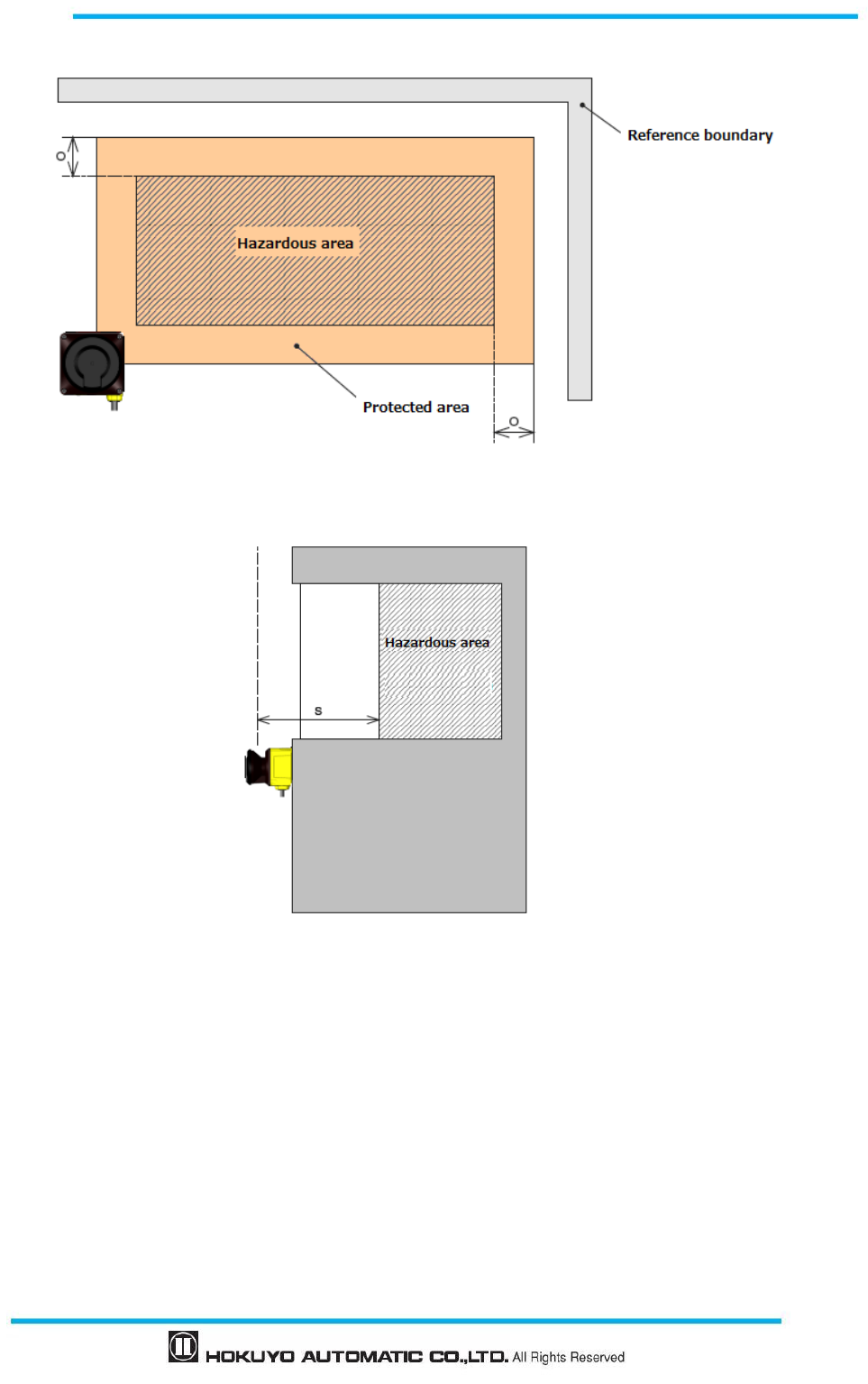
53
Document No: C-61-00003-3
Figure 4-8 Front view of access
Figure 4-9 Side view of access protection (For detection of body parts)
For Safety distance calculation
S= (K×(Tm+Ts)) + C
where
:
S = Safety distance (mm)
K = Approach speed 2000mm/s
Tm = Maximum stopping/run-down time of the machine or system (s)
Ts = Response time of UAM (s)
C = Additional distance
=
(
)
148
−
×
d
d = Minimum detectable object width (mm)
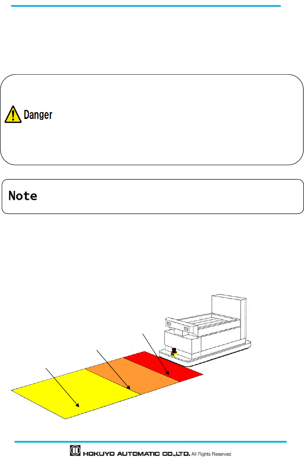
Document No: C-61-00003-3
54
O = Additional width from edge of hazard source
(
)
dZ
s
−×≥ 2
d = Minimum detectable object width (mm)
Zs= UAM’s tolerance distance (mm)
4.5 Area protection (Horizontal application Mobile) Fixed area
UAM can be used for mobile applications such as AGV (Figure 4-10). It is installed on an AGV to
detect objects while travelling along a fixed route. Warning signals in such application can be used for
reducing the speed and stop the AGV. A maximum 32 area sets can be used to match the travel route of the
AGV. Confirm the time and distance required for the AGV to stop completely when configuring the
protection and warning zones. The safety distance for this application is shown in figure 4-11 and 4-12.
Figure 4-10 Example of area protection (Mobile)
In the access protection application, where the angle of the approach exceeds ±30º,
“Reference boundary monitoring” function should be used.
Reference segments should be configured on each sides of reference boundary.
Tolerance of the reference segment should be less than 100mm.
For detection of body parts, minimum detectable width should be configured as 30mm
.
UAM should be mounted in such a way that it is impossible to access the hazardous
point. Use additional protective measures if necessary.
When the S > 500mm, value for K can be replace with 1600mm/s instead of 2000mm/s.
However, minimum value of S will be 500mm in such cases.
Protection zone
Warning zone 1
Warning zone 2
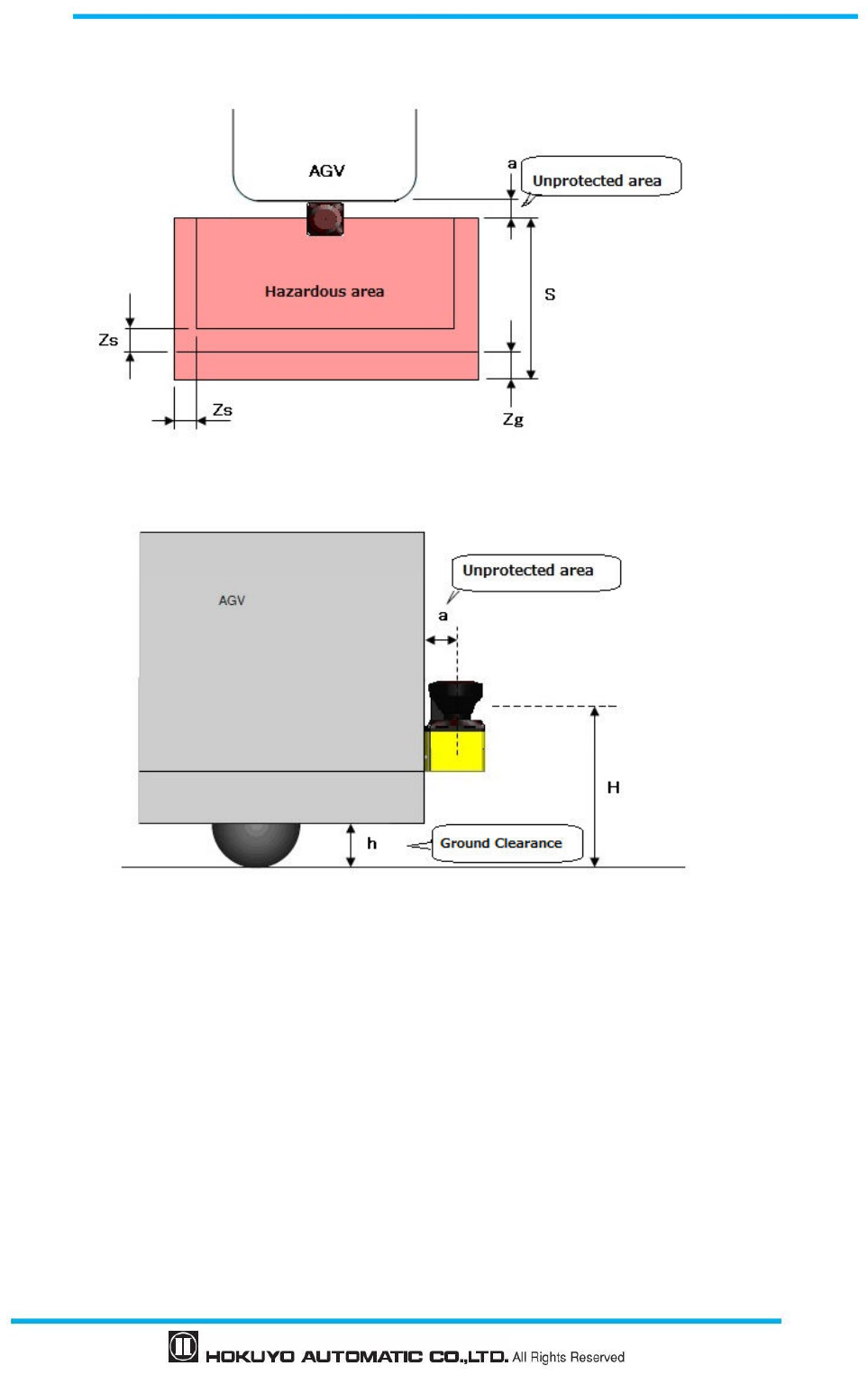
55
Document No: C-61-00003-3
Figure 4-11 Top view of area protection (Mobile)
Figure 4-12 Side view of area protection (Mobile)
For Safety distance calculation:
(
)
gsbsm ZZLZTTVS
+
+
×
+
+
×
=
where:
S = Safety distance (mm)
V = Maximum approaching speed of AGV (mm/s)
Tm = Maximum stopping/run-down time of the machine or system (s)
Ts = Response time of UAM (s)
Zb = Distance required for AGV to stop (mm)
L= Brake wear coefficient
Zs = UAM tolerance distance (mm)
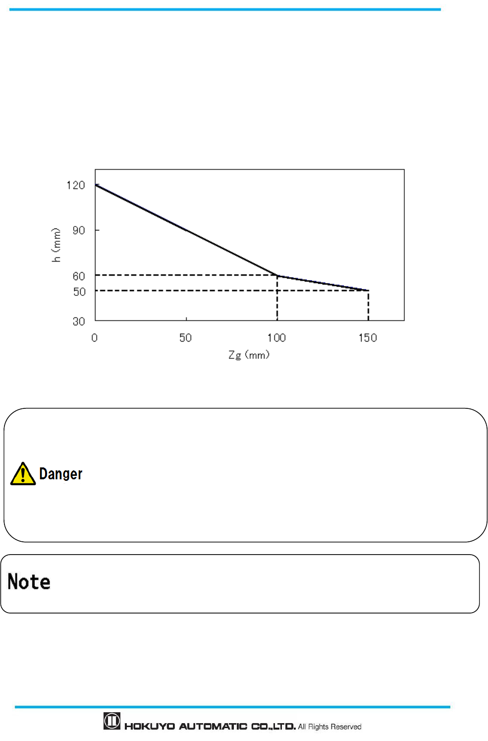
Document No: C-61-00003-3
56
Zg = Additional of distance with the lack of ground clearance (mm)
h = Ground clearance (mm)
When using the UAM on an AGV, user should confirm the time and distance required for the AGV to
stop completely as it will move forward during the response time of UAM. It is important to note that
distance required to stop is not proportional to the speed, but proportional to the square of the speed.
Further, sufficient ground clearance should be provided to prevent injuries, such as, hitting the toes.
Figure 4-13 shows the relationship between ground clearance h and Zg.
Figure 4-13 The relationship between Zg and h
User should ensure that the width of unprotected area “a” is
smaller than the minimum
detectable width. When the distance
“a” is greater than minimum detectable width,
additional protective measures should be t
aken to prevent the penetration through this
unprotected area.
UAM should not be mounted higher than 200mm to prevent the possibility of crawling
beneath the detection plane.
Detection plane should not be inclined as this could lead to the failure of UAM
to detect
an object with a diameter of 200mm.
User should ensure that boundary or protective measures used are not inside the configured
protected zone. It will be detected as obstacles causing the OSSD to remain in OFF-state.
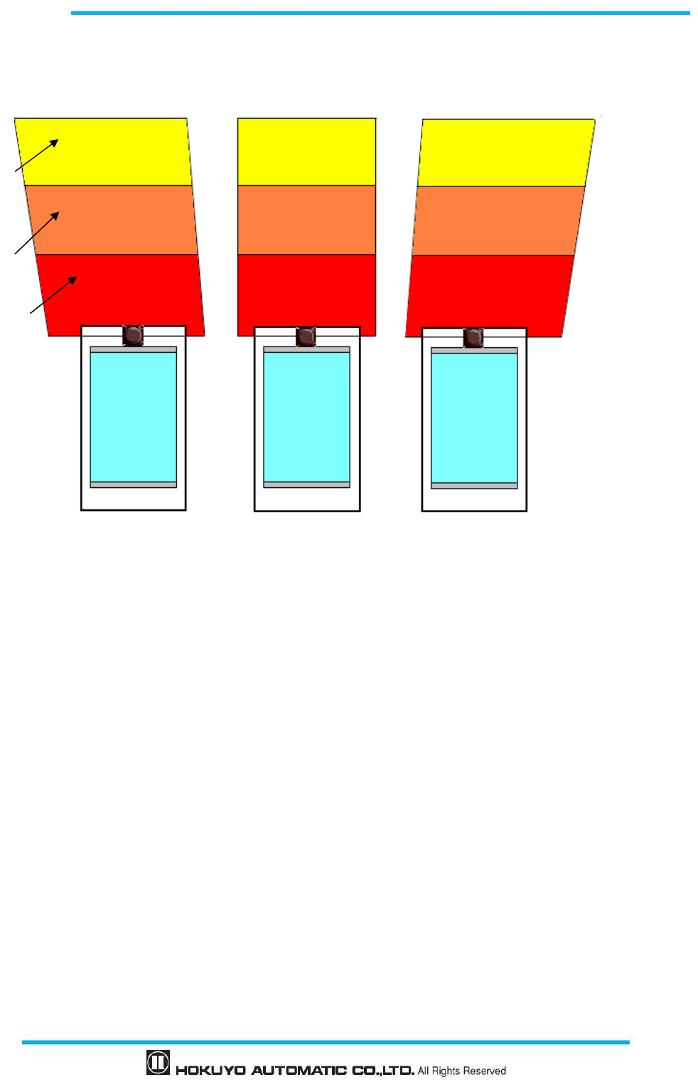
57
Document No: C-61-00003-3
4.6 Area protection (Mobile, Horizontal, Single Protection, Variable Area)
For applications where AGV travels in a single direction, it is possible to switch to different areas at
corners for effectively monitoring the obstacles at front (Figure 4-14).
Left turn Straight Right turn
Figure 4-14 one example of AGV scanning area at curve (Top view)
Protection zone
Warning zone1
Warning zone 2
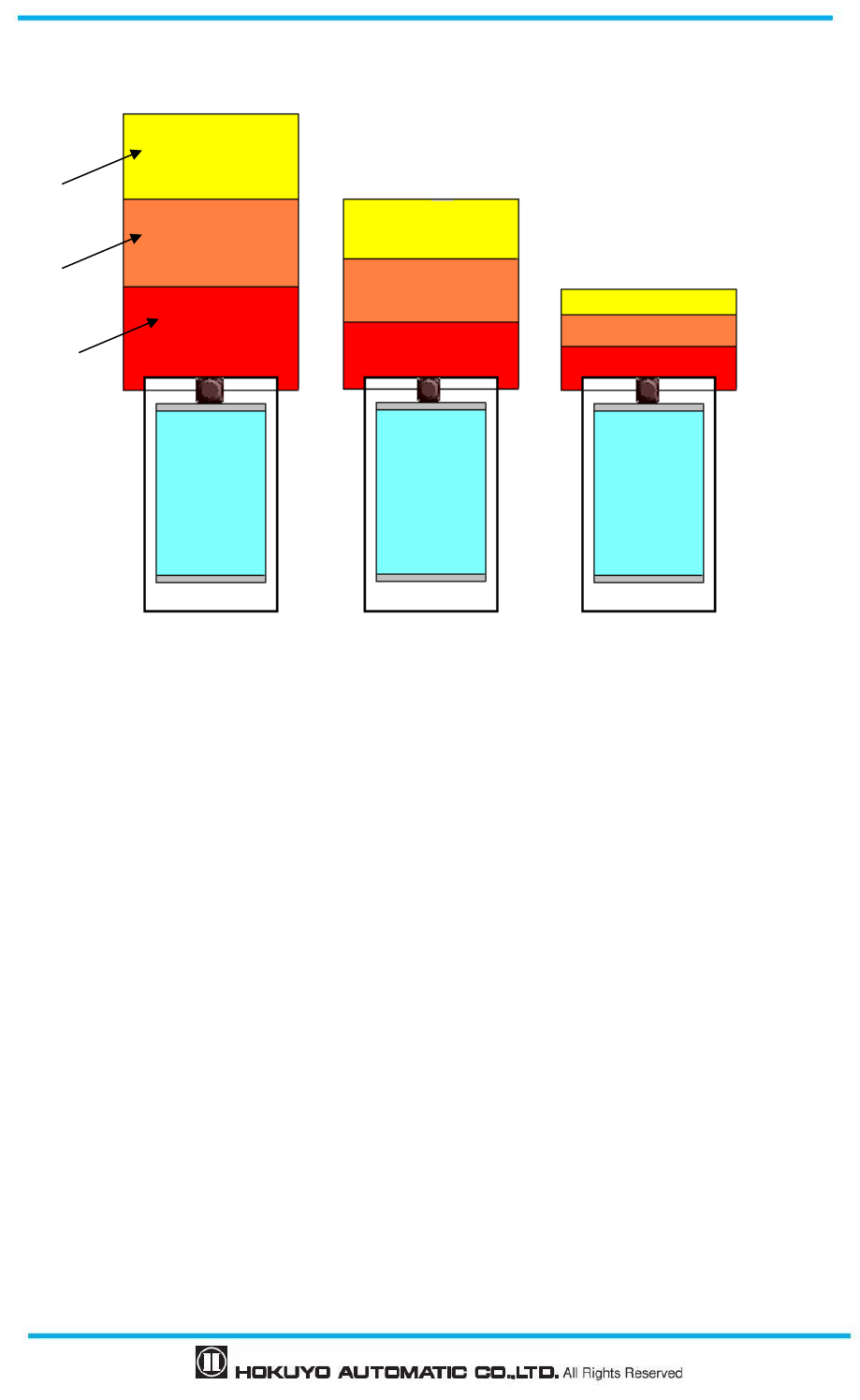
Document No: C-61-00003-3
58
4.7 Area protection (Mobile, Horizontal, Single Protection, Encoder Input)
When incremental encoder is used, area can be switched depending on the speed of AGV (Figure 4-15).
High speed Medium speed Low speed
Figure 4-15 Example of AGV’s scanning area depending on the speed (Top view)
4.8 Area protection (Mobile, Horizontal, 2 Units Interconnected, Variable
Area)
For AGVs travelling in both directions, it is possible to use 2 interconnected units of UAM, each
mounted at front and back. Safety can be improved by switching each unit to monitor the area with
appropriate size and shape based on the speed and direction of travel. Further, it is also possible to use
incremental encoder in such systems for area switching.
Protection zone
Warning zone 1
Warning zone 2
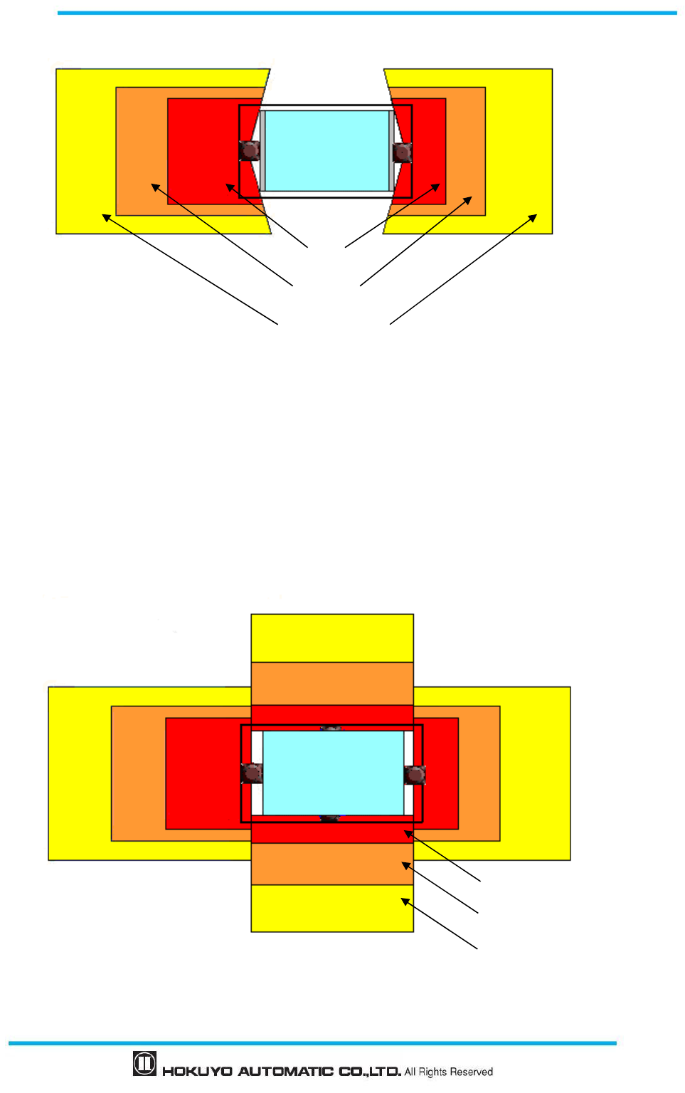
59
Document No: C-61-00003-3
Figure 4-16 Example of AGV’s scanning area which can travel in both the direction (Top view)
4.9 Area protection (Mobile, Horizontal, 4 Units Interconnected, Variable
Area)
For AGVs travelling in all directions it is possible to use 4 interconnected units of UAMs mounted on
each side of AGV. Safety can be improved by switching each unit to the area with appropriate size and shape
based on the speed and direction of travel. Further, it is also possible to use incremental encoder in such
systems for area switching.
Figure 4-17 Example of AGV’s scanning area which can travel in all the direction (Top view)
Protection zone
Warning zone 1
Warning zone2
Protection zone
Warning zone 1
Warning zone 2
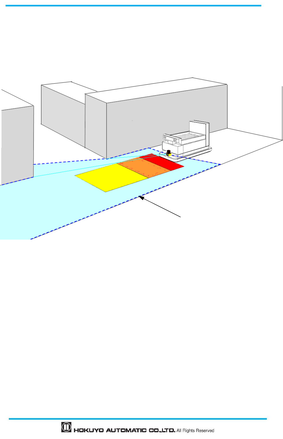
Document No: C-61-00003-3
60
4.10 Area protection (Mobile, Horizontal, Autonomous Navigation)
UAM monitors both protection and warning zones and simultaneously transfers the measured data of
the surrounding through the Ethernet to the main control unit of AGV. Supplied data can be used for
autonomous route selection. For such systems, there is no need to install guidance means such as optical
beacons or electromagnetic tapes on the floor. Refer to UAM-05LP communication protocol (C-64-00012)
for the Ethernet communication protocol.
Figure 4-18 Image of automatically operated AGV
4.11 Default Values
When configuring the device, default settings will be set is depending on the type of application selected
on the configuration software, UAM Project Designer. Table 4-1 shows the selected values.
Area will not be configured to any default value when selecting the applications. Configure the
appropriate area by calculating the safety distance or based on the risk assessment performed on the system.
Perform pre-operation tests on UAM to verify the correctness of the selected parameters.
Surrounding outline data

61
Document No: C-61-00003-3
Table 4-1 Default values for selected applications
Applications
Sensing Interlock Reference
Monitoring
(Tolerance)
Off response time
(Common to all areas)
Minimum
detection width
Active
areas
Start/Restart
Setting Delay
General 70mm 1 - - - 150ms
Access protection
(Horizontal application Stationary) 70mm 1 Manual/Auto
1s - 150ms
Access protection
(Vertical application- whole body detection) 70mm 1 Manual/Auto
1s Used
(100mm) 90ms
Access protection
(Vertical application Stationary) 30mm 1 Manual/Auto
1s Used
(100mm) 90ms
AGV 70mm 32 - - - 120ms
*Check the settings for each function and verify that they match the system requirements. Modify the values
if necessary.
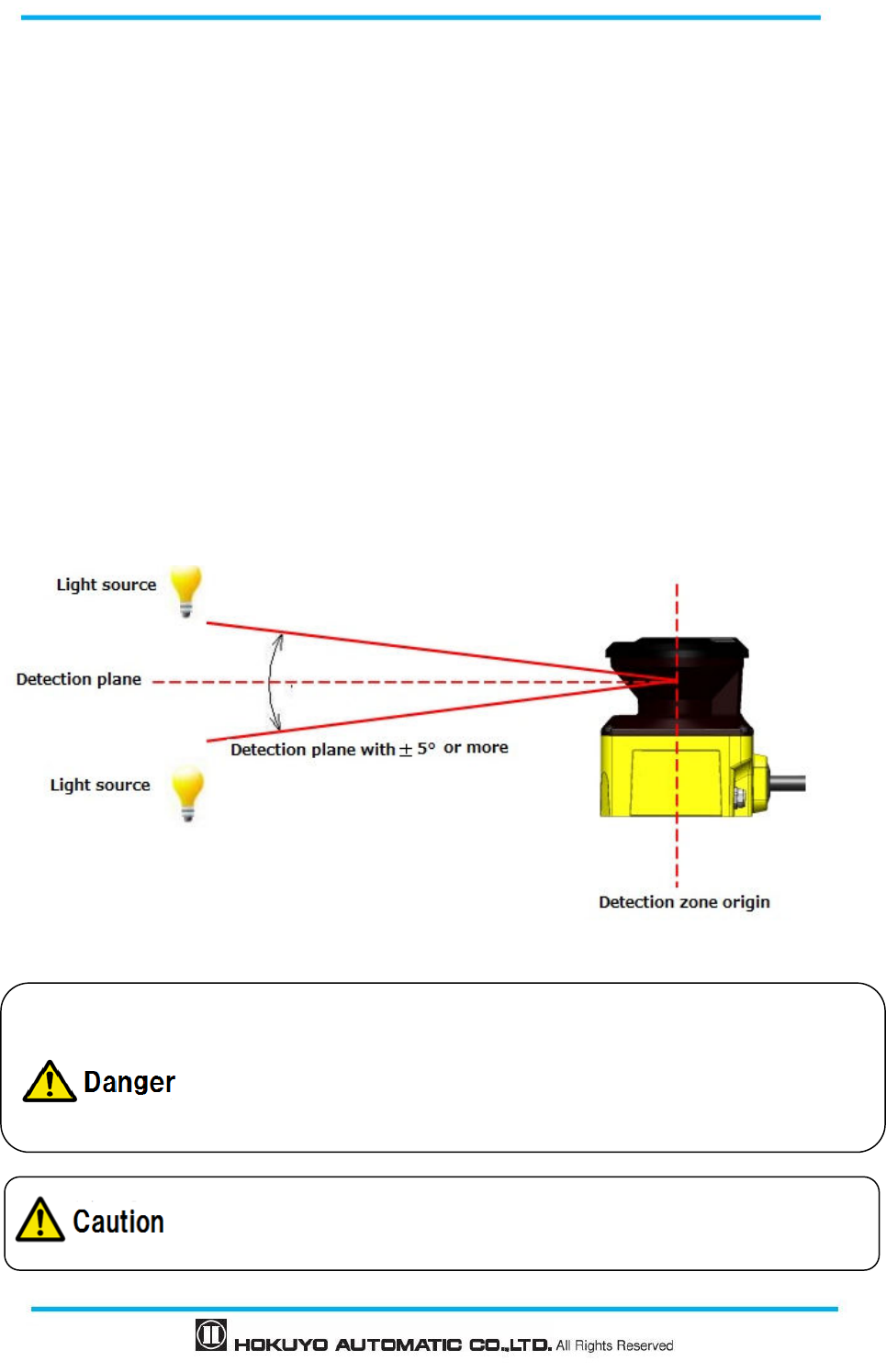
Document No: C-61-00003-3
62
5. Installation
Cautions during the installation of UAM are explained in this chapter.
5.1 Light interference
UAM uses pulsed laser for object detection. Light sources in the surrounding could interfere with its
operation leading to false detection. User should examine the surroundings environments before installing
the UAM. Some of the light sources that could interfere with UAM are as below.
Incandescent light
Fluorescent light
Stroboscopic light
Flashing beacon
Sunlight
Infrared light sources
In case the light source cannot be avoided during the operation, UAM should be installed with the light
source located at ±5 degrees or more from the detection plane to prevent the interference (Figure 5.1).
Figure 5-1 Installation to avoid light interference
User should perform risk assessment for light interference in the working
environment before the installation.
Avoid direct light such as stroboscopic, flashing beacon, fluorescent.
Failing to comply with the above could lead to critical injury or death.
User should verify detection capability before actual operation.
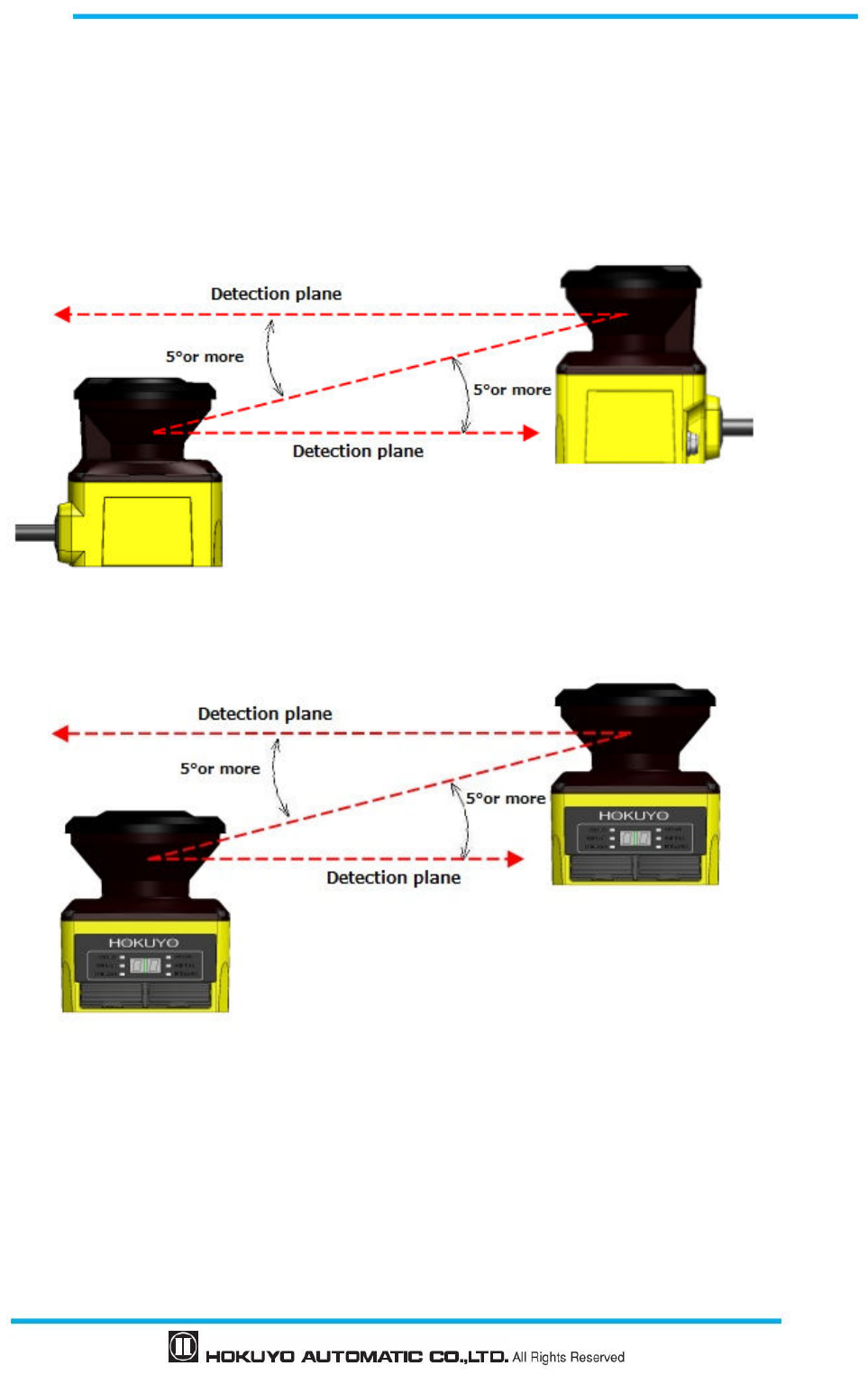
63
Document No: C-61-00003-3
5.2 Mutual interference
Cautions are required while using two or more units of UAM or identical products as pulsed laser signal
from one another could lead to false detection. Figures below show the installation method for avoiding the
mutual interference.
a) Changing the height of installation
Install at different heights to separate the mutual detection plane by 5 degrees or more.
Figure 5-2 Opposite facing installation
Figure 5-3 Parallel installation
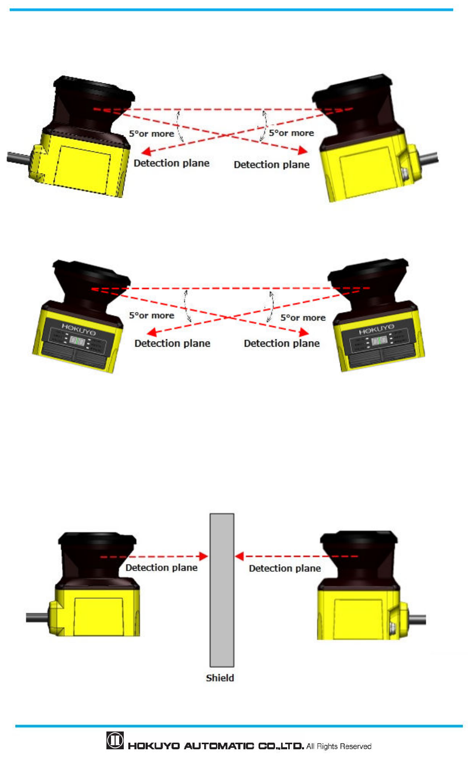
Document No: C-61-00003-3
64
b) Changing the angle of installation
Change the installation angle of UAM by 5 degrees or more from the mutual detection plane.
Figure 5-4 Opposite facing installation
Figure 5-5 Parallel installation
C) Adding a shield between UAMs
Add a shield between UAMs such that laser beam of one unit cannot reach the other to avoid the possible
mutual interference.
Figure 5-6 Opposite facing installation
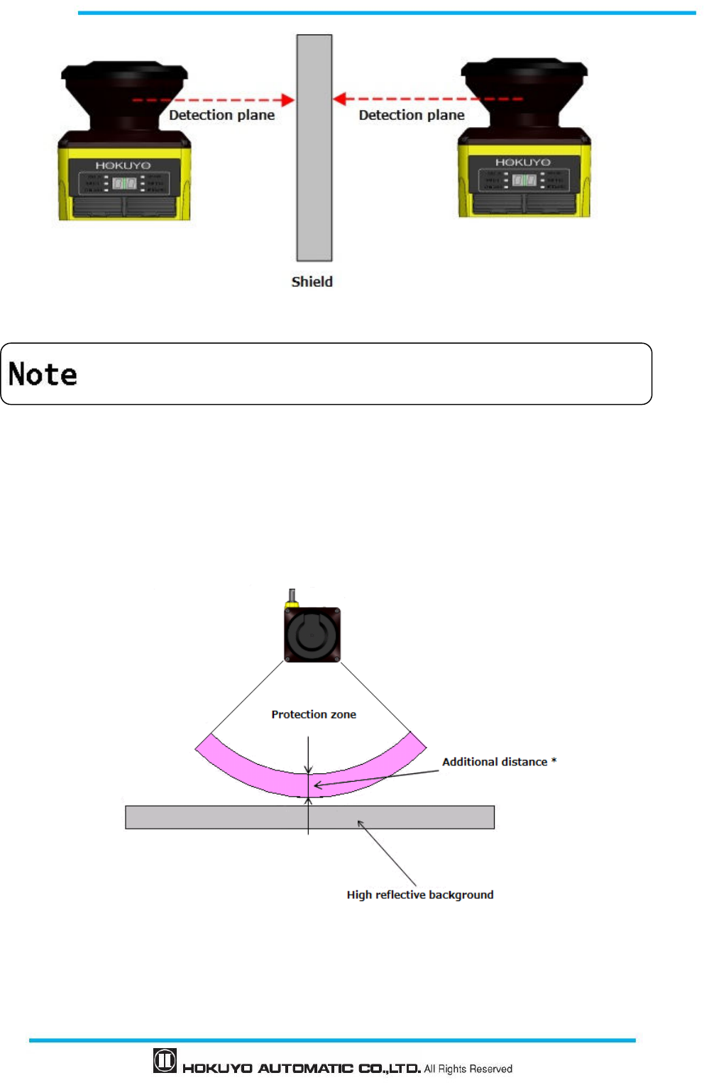
65
Document No: C-61-00003-3
Figure 5-7 Parallel installation
5.3 High reflective background
Measured value will be longer than the actual distance of the object due to high reflective background
leading to wrong OSSD output. When high reflective background cannot be avoided in the working
environment, additional distance of 200mm is necessary while configuring the protection and warning zones
(Figure 5-8). Refer to UAM’s specification for the required distance tolerance.
* Additional distance : Required additional distance when operating UAM under high reflective background
Figure 5-8 Additional distance in high reflective background
Shielding material should be opaque.
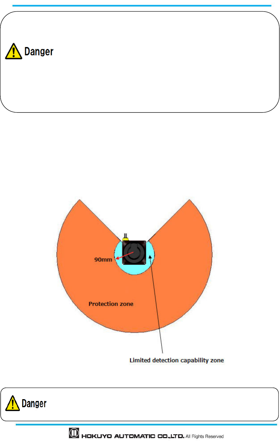
Document No: C-61-00003-3
66
5.4 Limited detection capability zone
The limited detection capability zone is defined as a region between the optical window and start of the
detection zone. The limited detection capability zone of the UAM is 90mm from the origin of UAM (Figure
5-9). Presence of object with low reflectance may not be detected in this zone.
Figure 5-9 Limited detection capability zone
Measured value will be longer than actual distance of the object if the
background is highly reflective. Additional distance should be included when
configuring the protection zone.
High reflective background (Ex.: Mirror, corner cube reflector, reflective safety
jacket, road reflector) should be avoided. Reflectance caused by these materials
could lead to false detection in the protection zone.
Verify the configured areas before actual operation.
Failing to comply with the above could lead to critical injury or death.
User should perform risk assessment for possibility of object penetration into
the limited detection capability zone.
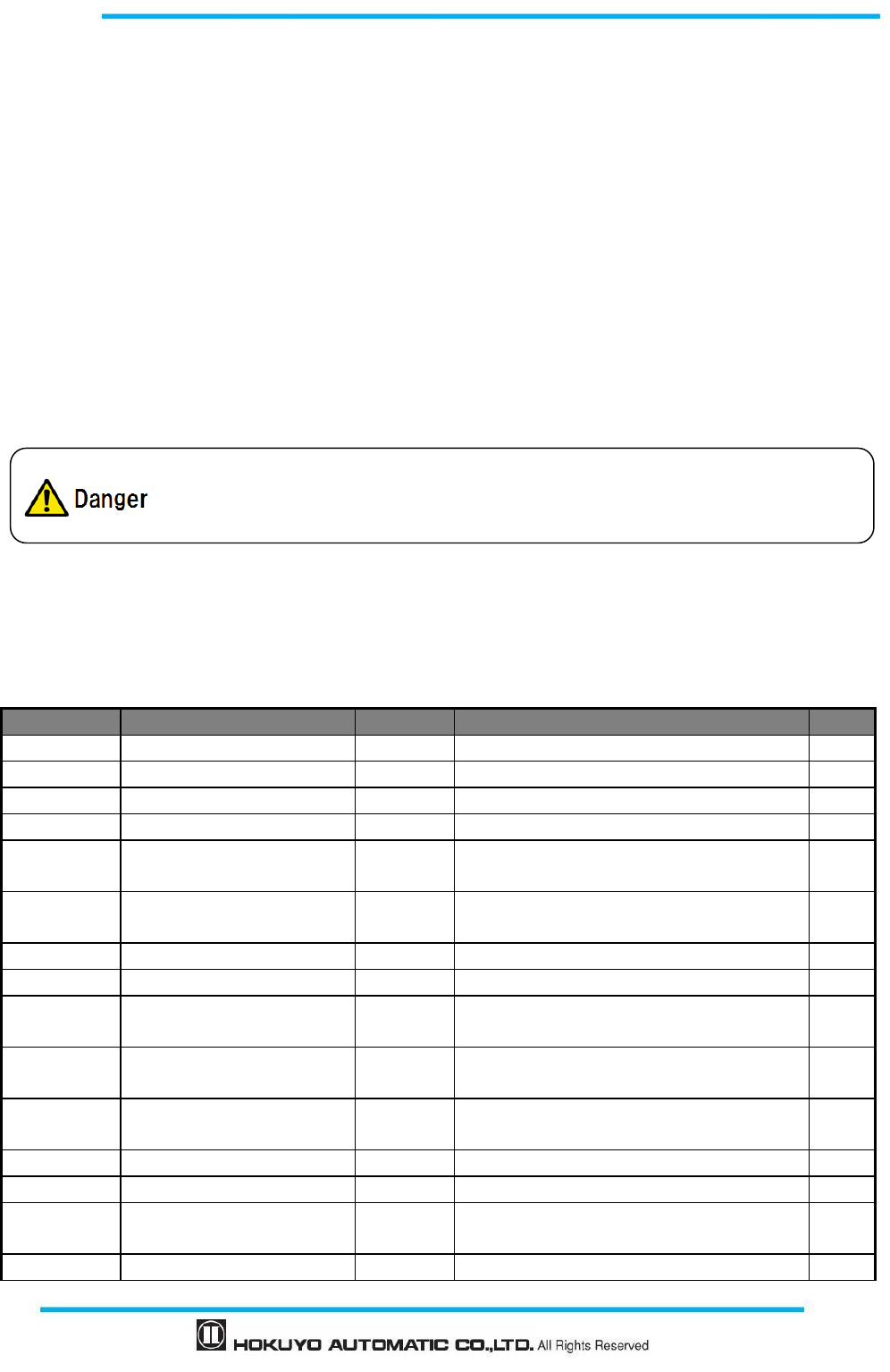
67
Document No: C-61-00003-3
6. Wiring
This chapter describes safety precaution when wiring the UAM.
6.1 Precautions
During electric wiring make sure that all devices are disconnected from power supply. Switch off all the
power supply during wiring. Confirm that power supply is OFF.
Do not exceed cable length stated in the specification of UAM.
6.2 Power supply
Make sure that power supply is within the range of DC 24V±10%. For battery operation, power supply
should be within the range of DC 24V -30% / +20%. UAM could be damaged if rated output voltage
exceeds this range.
6.3 Wire color and function
Table 6-1 shows the color of each lead wire, signal name and function. It is recommended to use the
shielded cable for wiring.
Table 6-1 Wire color and function
Color Signal Function Description AWG
Brown + 24 DC Power Power Supply: DC 24V
22
Blue 0V DC Power Power Supply: DC 0V
22
Red OSSD1 Output Protection zone output 1
26
Yellow OSSD2 Output Protection zone output 2
26
Red/Black WARNING 1/ OSSD3 Output Warning zone output 1/Protection zone output
3
28
Yellow/Black
WARNING 2/ OSSD4 Output Warning zone output 2/Protection zone output
4
28
Purple IN_A Input Area switching Input A
28
Gray IN_B/ MUTING 3 Input Area switching Input B / Muting input 3
28
White IN_C/OVERRIDE1/
ENC1_A Input Area switching Input C/Override input 1/
Encoder input 1_A
28
Pink IN_D/ MUTING 1/ENC1_B
Input Area switching Input D / Muting input 1/
Encoder input 1_B
28
Green IN_E/EDM1 Input Area switching Input E /External device
monitoring 1
28
Purple/Black
IN_A Input Area switching Input A invert
28
Gray/Black IN_B/ MUTING4 Input Area switching Input B invert / Muting input 4
28
White/Black
IN_C/OVERRIDE2/ENC2_A
Input Area switching Input C invert / Override input
2/Encoder input 2 A
28
Pink/Black IN_D/ MUTING2/ENC2_B
Input Area switching Input D invert / Muting input
28
For safety, switch OFF the power supply during electrical wiring.
Do not use cables longer than those mentioned in the specification of UAM.
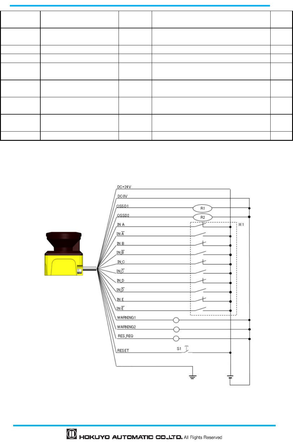
Document No: C-61-00003-3
68
2 /
Encoder input 2 B
Green/Black
IN_E/EDM2 Input Area switching Input E invert / External
device monitoring 2
28
Yellow/Green
RESET 1 Input Reset input 1
28
Yellow/Blue
RESET 2 Input Reset input 2
28
Orange RES_REQ1/MUT_OUT1 Output RES_REQ1: Request output 1
MUT_OUT1:Muting state output 1
28
Orange/Black
RES_REQ 2/MUT_OUT 2 Output RES_REQ2: Request output2
MUT_OUT2:Muting state output2
28
White/Blue
(TP)
RS485+ Communic
ation
Communication protocol RS485
28
White/Red
(TP)
RS485- Communic
ation
Communication protocol RS485
28
Shield wire FG -
--
- Frame ground
-
--
-
6.4 Wiring example
a) Standard (With maximum 32 sets of area)
Figure 6-1 Wiring Example 1
Frame ground
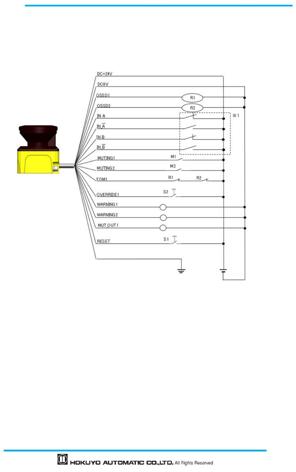
69
Document No: C-61-00003-3
R1 and R2: External equipment (Safety relay, Electromagnetic contactor)
S1: Interlock reset switch
*1: Refer to section 3.5 for the detail on area switching.
b) During EDM, muting and override function
Figure 6-2 Wiring Example 2
R1 and R2: External equipment (Safety relay, Electromagnetic contactor)
S1:Interlock reset switch
S2:Override switch
M1 and M2:Muting switch 1 and 2
*1: Refer to section 3.5 for the detail on area switching.
Frame ground
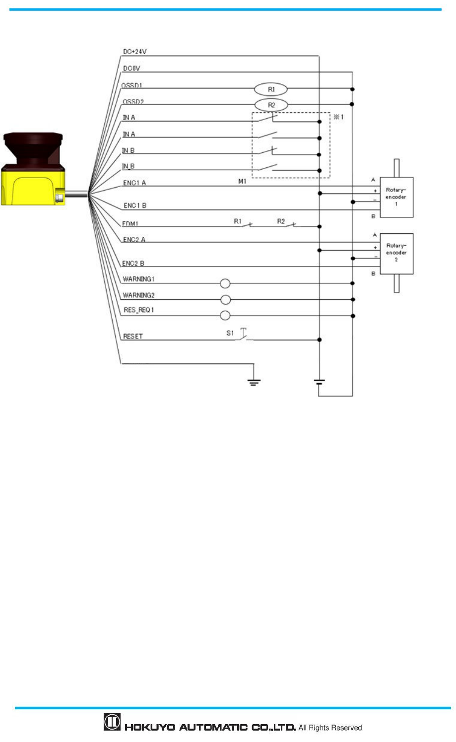
Document No: C-61-00003-3
70
c) During area switching during encoder input
Figure 6-3 Wiring Example 3
R1 and R2: External equipment (Safety relay, Electromagnetic contactor)
S1:Interlock reset switch
*1: Refer to section 3.5 for the detail on area switching and section 3.6.4 for encoder input.
Frame ground
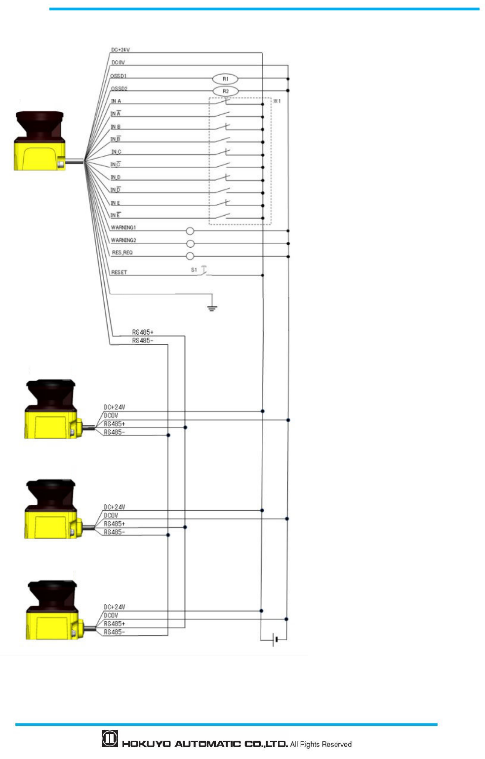
71
Document No: C-61-00003-3
d) During Master slave function when not using OSSD of slave
Figure 6-4 Wiring Example 4
R1 and R2: External equipment
(Safety relay, Electromagnetic contactor)
S1:Interlock reset switch
*1: Refer to section 3.5 for the detail
on area switching.
Frame ground
Master
Slave1
Slave2
Slave3
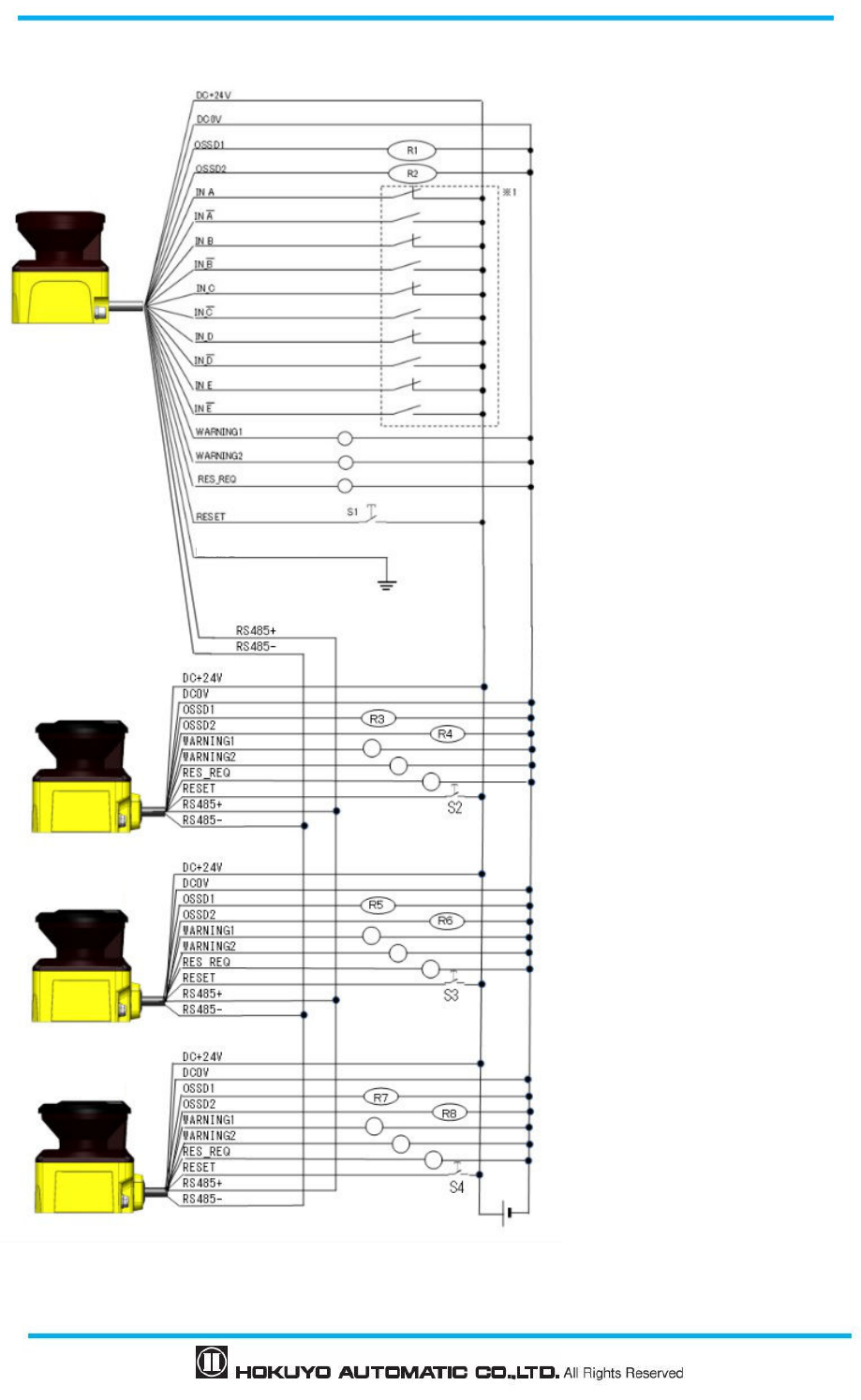
Document No: C-61-00003-3
72
e) During Master slave function when using OSSD of slave
Figure 6-5 Wiring Example 5
R1 – R8: External equipment
(Safety relay, Electromagnetic contactor)
S1-S4:Interlock reset switch
*1: Refer to section 3.5 for the detail
on area switching.
Frame ground
Master
Slave1
Slave2
Slave3
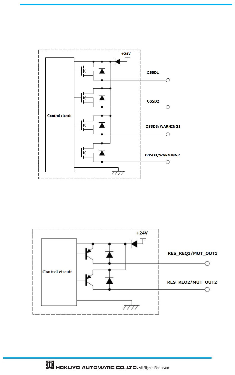
73
Document No: C-61-00003-3
6.5 Input/ Output circuit
6.5.1 OSSD/ Warning Output circuit
OSSD/Warning output is output source type
Figure 6-6 OSSD/WARNING Output circuit
6.5.2 Other output circuits
RES_REQ1, RES_REQ2, MUT_OUT1, MUT_OUT2 outputs are PNP type.
Figure 6-7 Output circuit
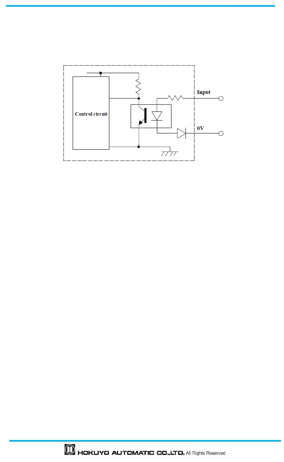
Document No: C-61-00003-3
74
6.5.3 Input circuit
Figure 6-8 shows input circuit for Area input, EDM1, EDM2, RESET1, RESET2, MUTING 1, MUTING
2, MUTING 3, MUTING 4, OVERRIDE 1, and OVERRIDE 2 signals.
Figure 6-8 Input circuit
75
Document No: C-61-00003-3
7. Function configuration of UAM
7.1 About UAM Project Designer application
UAM project designer is application software for UAM that is developed for the following functions.
Protection and warning zone configuration
Function configuration
Displaying the measurement data
Record and playback of measurement data
Project data management (saving and opening the project data).
7.2 System requirements
Table 7-1 Minimum system required for UAM Project Designer
Item Explanation
Interface USB 1.1/2.0
PC
CPU Pentium
®
IV processor of 800MHz or above
RAM 256MB or more
Hard disk 100MB minimum free space
Media Drive CD-ROM driver
Compatible OS
Microsoft
®
Windows
®
XP 32bit (SP3 or above)
Microsoft
®
Windows
®
7 32/64bit
Microsoft
®
Windows
®
8 32/64bit
Microsoft
®
Windows
®
8.1 32/64bit
Microsoft
®
Windows
®
10 32/64bit
Display High color (16bit color) or above , 800×600 dot or above
Operation cannot be guaranteed for the following system environment.
OS other than mentioned above.
NEC PC98 series and its compatible device.
Self-assembled PC
Multi boot environment
Multi monitor environment
Upgraded OS from the standard OS
Fi
gures, illustrations, display
s
and indications in this manual may differ depending
on user’s
system or environment settings.

Document No: C-61-00003-3
76
7.3 Installatiion of UAM Project Designer
a) Insert the CD into the CD-ROM drive.
b) Click “UAM Project Designer_*.*_installer.exe.
c) Follow the instructions to complete the installation.
7.3.1 Uninstallation UAM Project Designer
Process to uninstall the UAM Project Designer is as shown below.
a) Select all programs from the start menu.
b) Select “Uninstall UAM Project Designer” in the “UAM Project Designer” folder.
c) When “Are you sure you want to completely remove UAM Project Designer and all of its related
components?” message appears, click [Yes] to uninstall the program from the PC.
d) Click [OK] when uninstalling process is complete. Restarting the PC is recommended.
Following is the alternative method to uninstall the application,
a) Select the “Control Panel” in the start menu.
b) Click the “Uninstall Programs”.
c)
Select “UAM Project Designer” and click [Delete].
d)
When “Ready to uninstall
UAM Project Designer”
appears, click [Yes] to uninstall the program from the
PC.
Even if the system requirements are fulfilled, operation is not guaranteed in all
PCs.
Read the UAM user’s manual before configuration. User’s manual can be opened
from the help menu of UAM Project Designer.
Cover the USB connector and SD card slot with protective cap when UAM is
operating. Make sure that mist or dust does not enter the device.
Do not use the USB cable of mobile chargers. It is recommended to use a standard
USB cable and avoid the winding type.
Log in as “Administrator” to authorize the installation of the UAM Project
Designer.
Installation cannot proceed if PC is not running in “Administrator” mode.
UAM project designer is installed at “C:╲Program Files Hokuyo╲UAM Project
Designer” by default. To install in different folder, change this location during the
installation process.
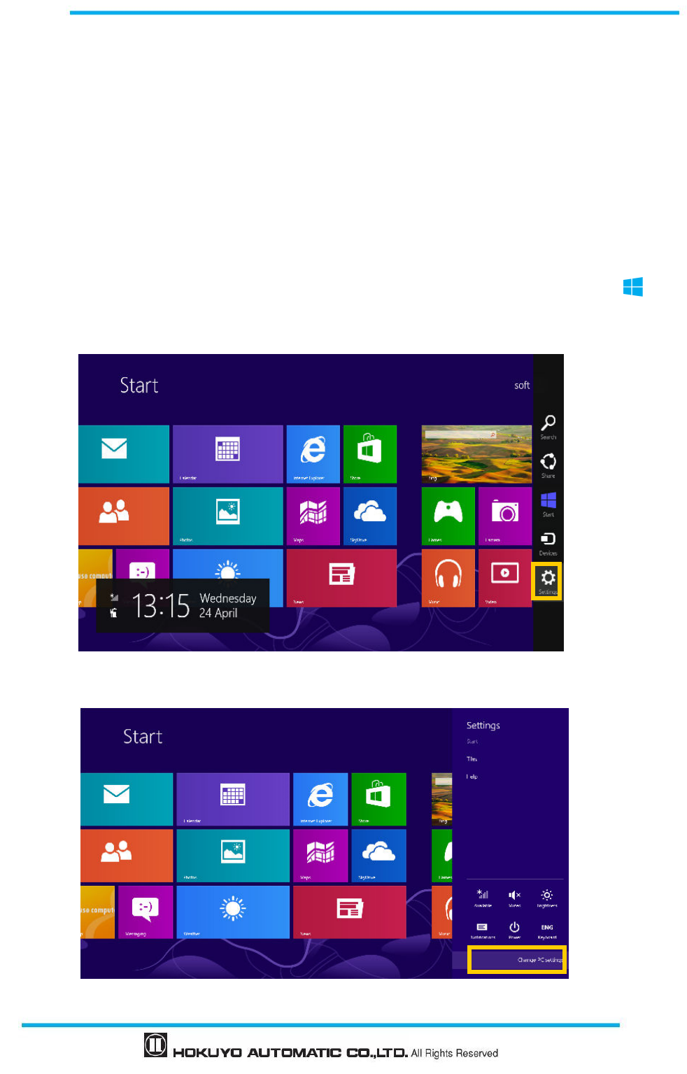
77
Document No: C-61-00003-3
e)
Click [OK] when uninstalling process is complete. Restarting the PC is recommended.
7.4 Device driver installation
7.4.1 Installing the driver in Windows 8
In Windows 8, permission setup is required before installing the USB driver.
Caution:
This step is not required for Windows 7. Proceed to section 7.4.2 for such OS.
This step is not required for Windows XP. Proceed to section 7.4.3 for such OS.
This step is not required for Windows 10. Proceed to step 7.4.4 for such OS.
a) Display the side menu by moving the mouse cursor to the top right or bottom right corner or click
Start Menu + “C key” and click on the “Setting”. When using a tablet, swipe from the right edge of the
screen towards the center.
Figure 7-1 Windows 8 Start screen
b) On the setting screen click the “Change PC setting” located at the bottom.
Figure 7-2 Sub menu of start screen
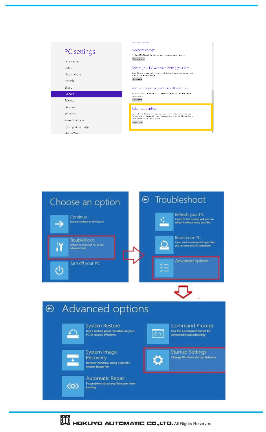
Document No: C-61-00003-3
78
c) On the PC setting screen, click the “General” and then “Restart Now” of “Advanced start-up” on the
list.
Figure 7-3 PC Setting screen
d) Wait for the system to restart.
e) On the option selection screen, click the “Troubleshooting” → “Detailed Options” → “Startup setting”
in order
.
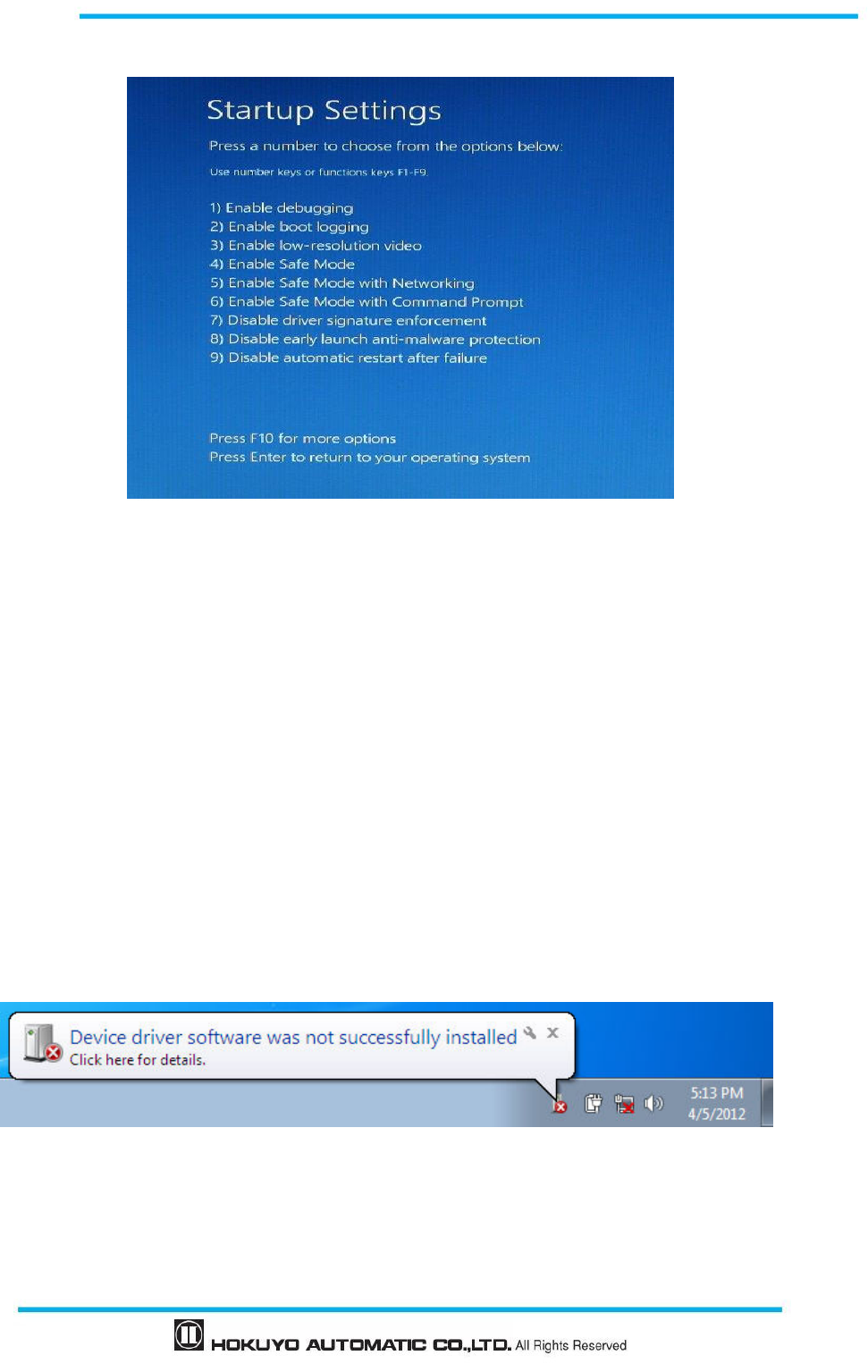
79
Document No: C-61-00003-3
Figure 7-4 Option selection screen
Figure 7-5 Startup setting screen
f) Click restart and wait for a while.
g) When startup setting is displayed, press F7 or 7.
After completing the setup, follow the process described in section 7.4.2 to install the driver. To view the
device manager used in the process, right click the mouse button on the empty start window panel and click
on the “all applications” and click on the “device manager”. Start from Step 4 (page 78) of installation
process for Windows7 described in section 7.4.2 to complete the driver installation.
7.4.2 Installing the driver in Windows 7
It is required to install USB driver when UAM is connected first time to USB port of a PC. Follow the steps
described below to complete the driver installation before running UAM Configurator application on
Windows7 operating system.
Step 1: Connect UAM to USB port of the PC. Following error message will appear on the screen.
Figure 7-6
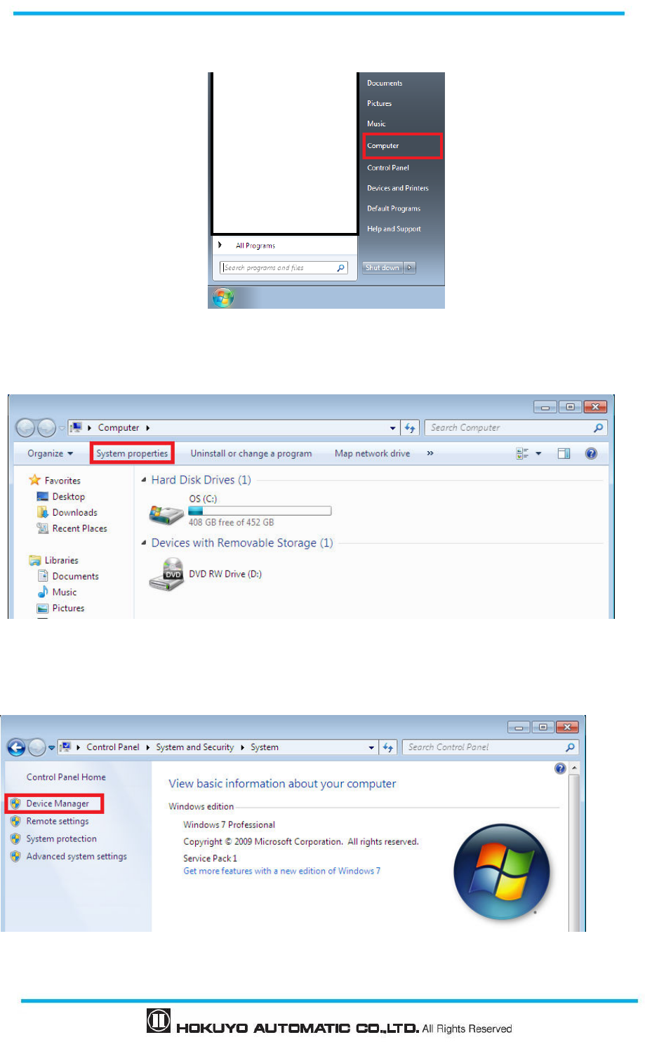
Document No: C-61-00003-3
80
Step 2: From windows start menu click [Computer].
Figure 7-7
Step 3: Click [System properties] on the menu.
Figure 7-8
Step 4: Click [Device Manager] button.
Figure 7-9
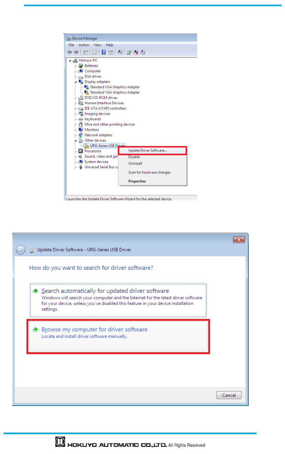
81
Document No: C-61-00003-3
Step 5: [URG-Series USB Driver] will be listed on [Other devices]. Right click on the [URG-Series USB
Driver] and click [Update Driver Software].
Figure 7-10
Step 6: Select [Browse my computer for driver software] when following message appears.
Figure 7-11
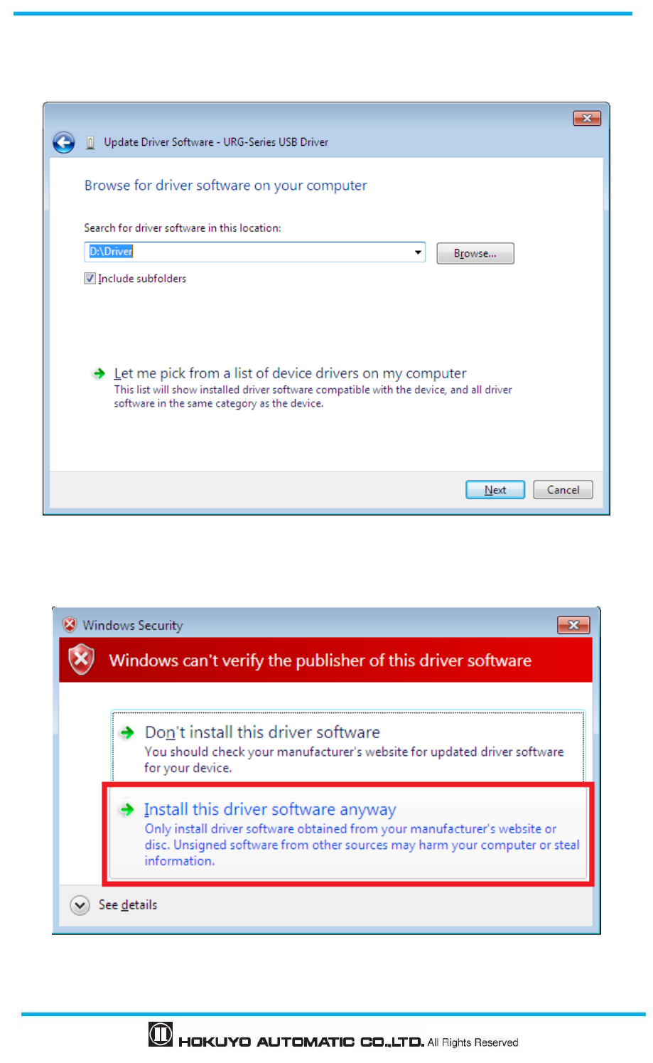
Document No: C-61-00003-3
82
Step 7: Insert installation CD on the PC. Click [Browse] button to select “Driver” folder in the CD and click
[Next] button
.
Figure 7-12
Step 8: Select [Install this driver software anyway] if following security message appears during installation.
Figure 7-13
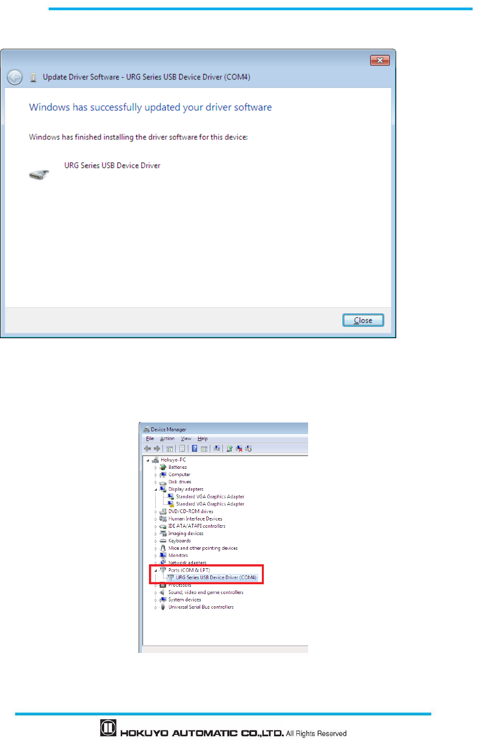
83
Document No: C-61-00003-3
Step 9: Installation is complete when following message appears on the screen
Figure 7-14
Step 10: Open device manager and confirm the presence of [URG Series USB Device Driver] listed under
[Ports (Com & LPT)]
Figure 7-15

Document No: C-61-00003-3
84
7.4.3 Installing the driver in Windows XP
This section explains the USB driver installation method in Windows XP. URG series USB driver is used by
UAM. Follow the steps below to install the driver.
a) Connect the UAM to PC’s USB port. When PC detects the new hardware open the “Found
New Hardware Wizard”
b) Select “Install from a list or specific location (Advanced)”. Insert the CD and click [Next>]
c) Select “Search for the best driver in these locations”. Select “Include this location in the search”, and
click [Browse]
d) Select the “Driver” folder and click [OK]
e) Click [Next>]
f) The Wizard starts searching for the driver and dialogue box is shown.
g) Windows starts installing the UAM driver.
h) After clicking [Finish], the dialogue appears indicating new hardware is successfully installed.
To confirm the successful installation go to computer’s device manager and expand the “Ports (COM and
LPT)” list. “URG Series USB Device Driver” should appear as one of the COM ports.
7.4.4 Installing the driver in Windows 10
This section explains the USB driver installation method in Windows 10. UAM can be connected with the
pre installed USB serial device driver in Windows 10. Therefore, installing the driver provided in the
package (URG Series USB Device Driver) is not necessary. Follow the steps before to install the windows
USB serial device driver.
Switch on the power supply to UAM and connect it with USB cable to Windows 10 PC. OS will
automatically detect the device and install the USB serial device driver. To verify the installation, open the
device manager, open the lists on “Ports (Com & LPT)” and look for “USB Serial Device (ComXX)”
(Figure 7-16). Use this com port number when connecting with UAM Project Designer.
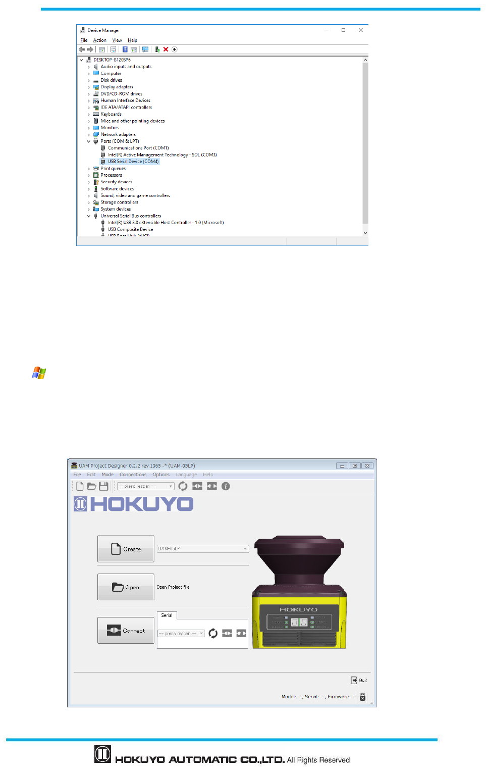
85
Document No: C-61-00003-3
Figure 7-16 USB Driver in Windows 10
7.5 Starting the UAM Project Designer
* Explanation of this section is based on Microsoft Windows XP. Although the display may differ slightly in
the other OS, same operation can be performed.
a)
Supply the Power to the sensor. Connect USB cable of the sensor to the computer.
b) Click “ Start Menu” → “All Programs” → and click “UAM Project Designer”.
c) “UAM Project Designer” application will be activated.
7.5.1 Startup Main window
a) Main window as shown in figure 7-17 will be displayed when UAM project designer starts.
Figure 7-17 Main window
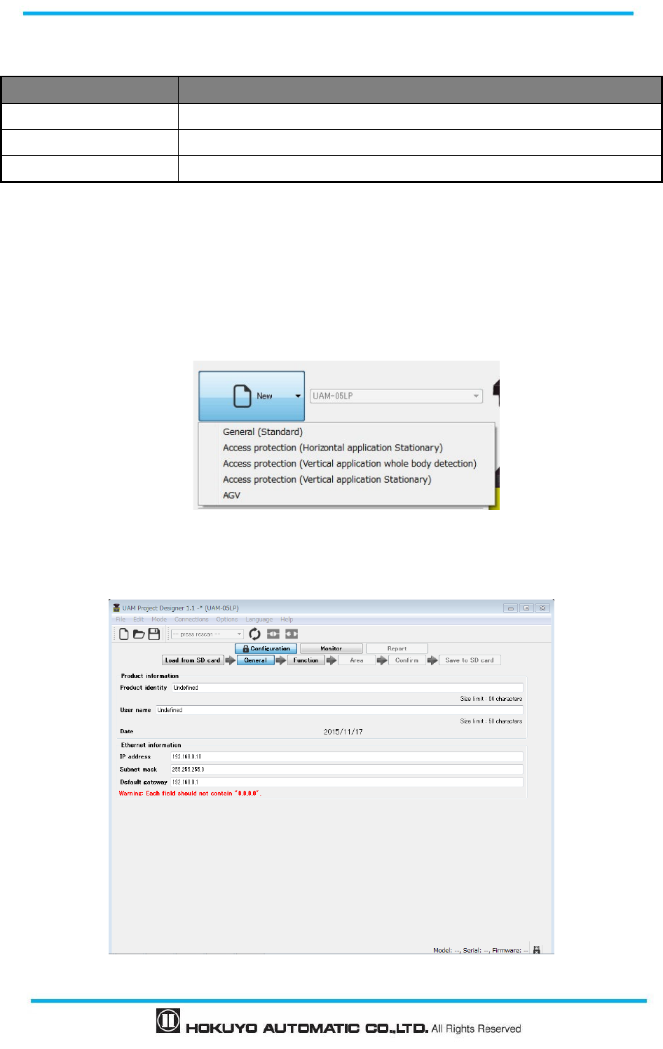
Document No: C-61-00003-3
86
b) Select the method to operate UAM.
Table 7-2 Operating Method
Method Description
Create Checks the firmware version and creates a new project file for UAM.
Open Opens an existing project file.
Connect Establish communication between PC and sensor.
7.5.2 Create new configuration
When new is selected, a list of application examples as shown in Figure 7-18 will be displayed. Refer to
section 4 for the details on these applications and section 4.11 for the default setting values selected by the
application. Window as shown in Figure 7-19 will appear when any one of these applications are selected.
Enter the necessary information such as product identity, user name and click function to continue the
setting.
Figure 7-18 Application selection window
To change the IP address of UAM, enter the value in the Ethernet information.
Figure 7-19 New configuration window
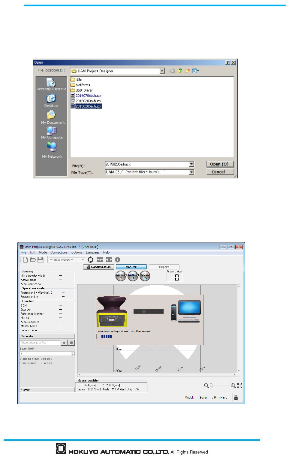
87
Document No: C-61-00003-3
7.5.3 Open configuration file
When the open is selected, a window as shown in figure 7-20 will be displayed. Select the previously
saved project, click open to read the settings. Modify the settings if required. Confirm all the settings and
proceed to transmit to transfer the configuration to UAM.
Figure 7-20 Selection of project file
7.5.4 Connect to UAM
When Connect button is selected, a window as shown in figure7-21 is displayed indicating the information
are being read from UAM. When the settings are successfully read, UAM project designer will switch to
monitor mode.
Figure 7-21 Connecting with UAM
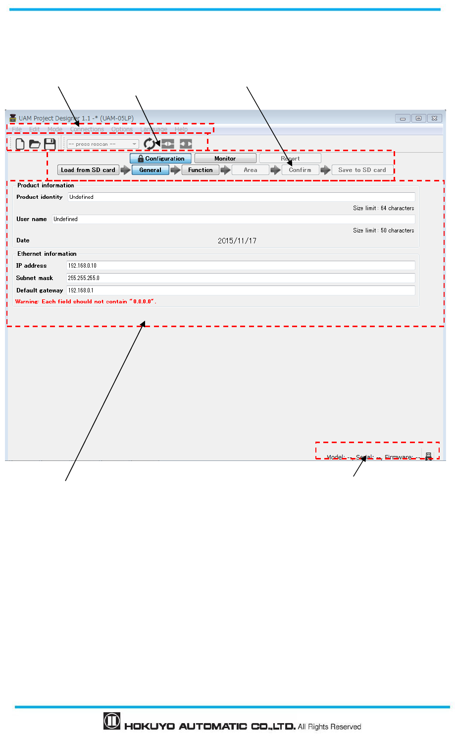
Document No: C-61-00003-3
88
7.6 Components of UAM Project Designer
Figure 7-22 shows the name of each component on the main window.
Figure 7-22 UAM Project Designer components
Menu bar Tool bar Sub panel
Main window Status bar
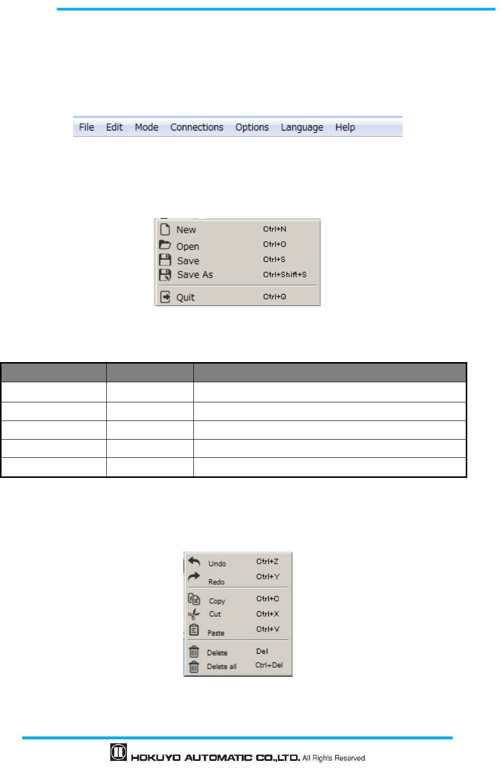
89
Document No: C-61-00003-3
7.7 Menu bar
This section explains the functions of all items in the menu bar. Function can be executed by either clicking
the respective items or by the short-cut key. When UAM is not connected, some items are in gray and cannot
be clicked
7.7.1 File
This menu is used for creating and saving the project file and closing the application. When file is clicked,
items as shown in the figure 7-23 will be displayed. Table 7-3 displays the details of each item.
Figure 7-23 File menu
Table 7-3 File menu
Item Short-cut Key
Function
New
Ctrl+
N
Create a new configuration file for UAM
Open
Ctrl+O
Open an existing configurations file
Save
Ctrl+S
Save the current project file
Save As
Ctrl+Shift+S
Save the current project file after naming
Quit
Ctrl+Q
Close the UAM Project Designer
7.7.2 Edit
This menu is used for editing the area. When edit is clicked, items as shown in the Figure 7-24 will be
displayed. Table 7-4 displays the details of each item.
Figure 7-24 Edit
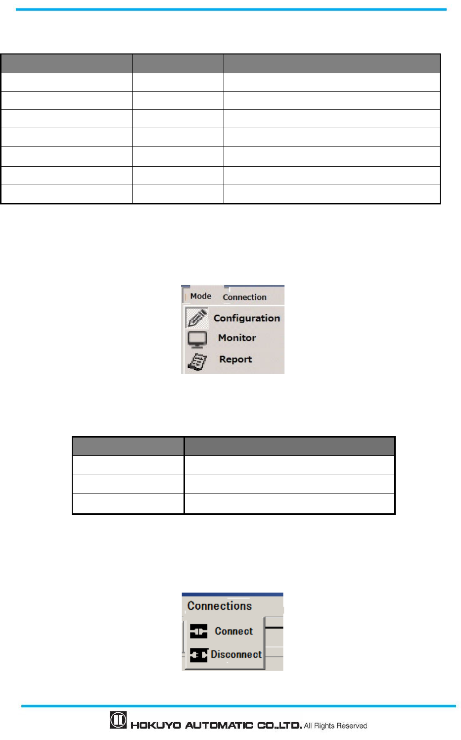
Document No: C-61-00003-3
90
Table 7-4 Edit
Item Short-cut Key Function
Undo
Ctrl+Z
It will undo the previous operation.
Redo
Ctrl+Y
It will redo the last operation.
Copy
Ctrl+
C
Copy single area.
Cut
Ctrl+
X
Cut single selected area. Delete the original area.
Paste
Ctrl+
V
Paste the selected area in other area.
Delete
D
el
Delete the single selected zone.
Delete all
Ctrl+
Del
Delete all the selected area.
7.7.3 Mode
This menu is used for changing the mode of the UAM. Items in the menu are shown in Figure 7-25. Function
of each mode as shown in the Table 7-5.
Figure 7-25 Mode
Table 7-5 Mode
Item Function
Configuration mode Configure the UAM settings
Monitor mode Monitor the UAM operation.
Report View UAM setting and error information
7.7.4 Connection
When connection is clicked, items as shown in the Figure 7-26 will be displayed. Table 7-6 shows the
details of each item. When UAM is not connected these items are in gray and cannot be selected.
Figure 7-26 Connection
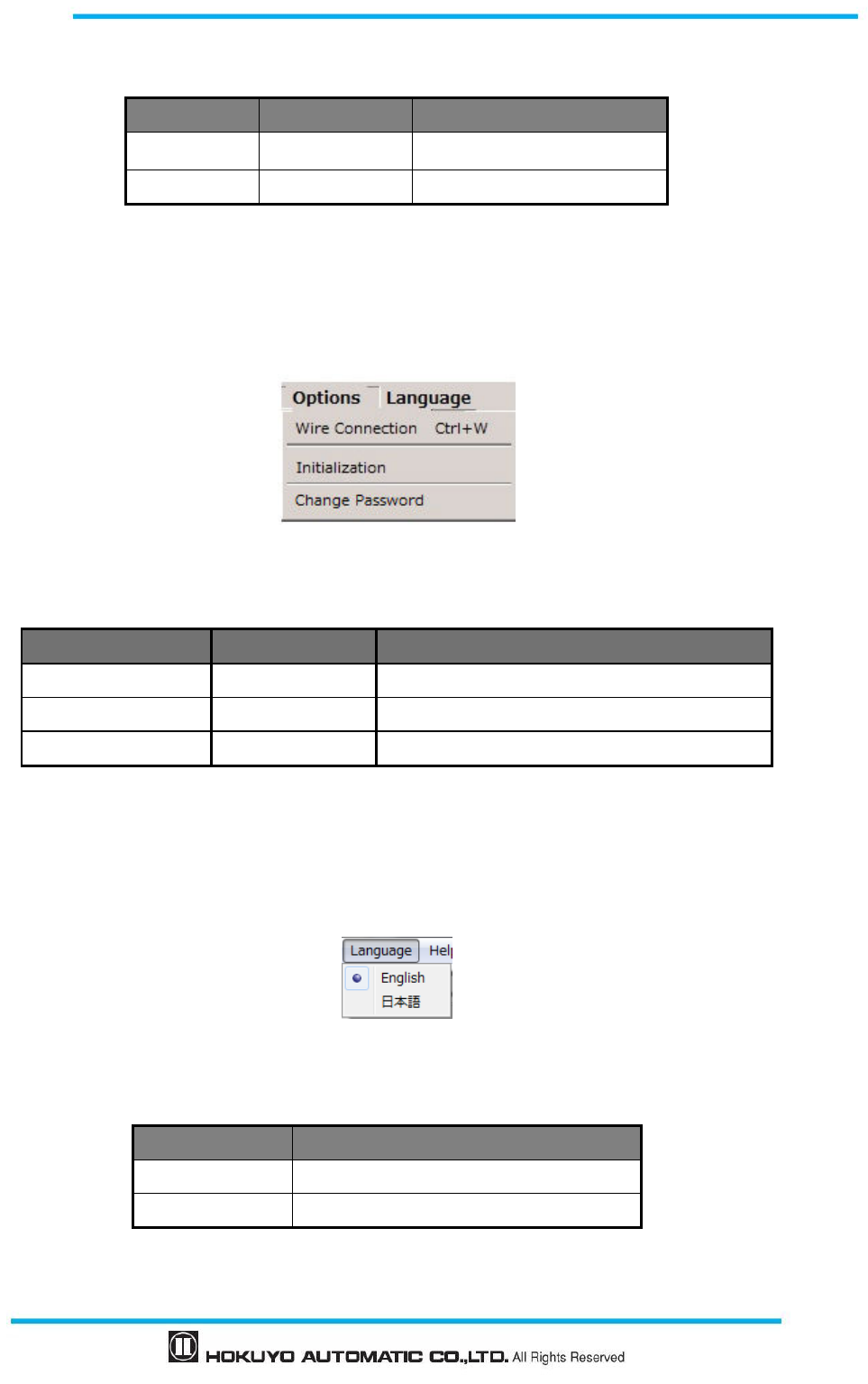
91
Document No: C-61-00003-3
Table 7-6 Connection
Item Short-cut key Function
Connect ― Connects to UAM
Disconnect ― Disconnects UAM
7.7.5 Option
When option is clicked, items as shown in the Figure 7-27 will be displayed. Table 7-7 shows the details of
each item. When UAM is not connected some items are in gray and cannot be selected.
Figure 7-27 Option
Table 7-7 Option
Item Short-cut key Function
Wire Connection
Ctrl+W
Wire color and function assignment
Initialization ―
Clear UAM’S configurations to default
Change Password ― Change to new 8-digit numeric password
7.7.6 Language
This menu is used for changing the application language to English or Japanese. Items in the menu are
shown in the Figure 7-28. Table 7-8 shows the details of each item.
Figure 7-28 Language
Table 7-8 Language
Item Function
日本語 Displays in Japanese language
English Displays in English language
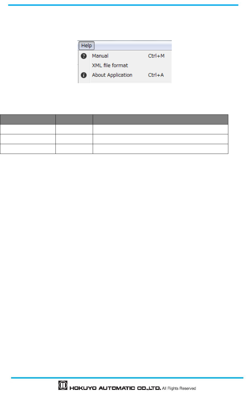
Document No: C-61-00003-3
92
7.7.7 Help
When help is clicked, items as shown in the Figure 7-29 will be displayed. Table 7-9 shows the details of
each item.
Figure 7-29 Help
Table 7-9 Help
Item Short-cut key
Function
Manual Ctrl+M Displays the user manual
XML file format - Displays format details of XML file
About the application
Ctrl+A Displays the version details of UAM Project Designer
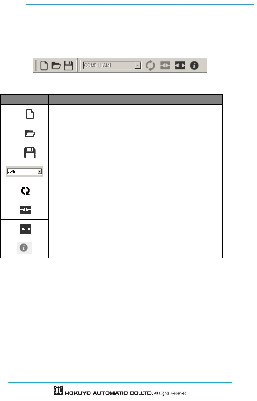
93
Document No: C-61-00003-3
7.8 Tool bar
Frequently used functions are listed on the tool bar. Details of the item are shown in table 7-10. When
UAM is not connected some items are displayed in gray and cannot be selected
Table 7-10 Tool bar
Icon Function
Creates a new configuration file for UAM
Opens a saved file.
Saves the project file.
Displays the port number connected to UAM.
Rescan the USB port
Establish connection between the sensor and UAM Project Designer.
Disconnect sensor with UAM Project Designer.
Sensor information
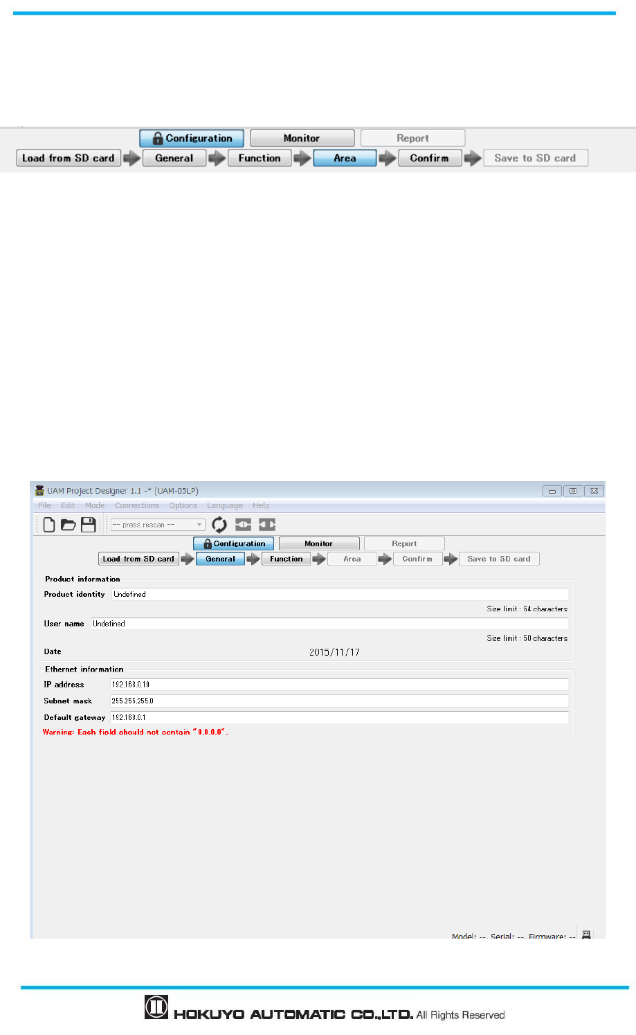
Document No: C-61-00003-3
94
7.9 Subpanel
This subpanel is used for switching the UAM modes (Configuration, Monitor and Report). When items
cannot be used they are displayed in gray.
7.9.1 Configuration tab
There are 6 tabs under the configuration main tab (Load from SD card, General, Function, Area, Confirm
and Save to SD card). Users can configure UAM by sequentially selecting these tabs.
A) Load settings
User can read the settings from UAM or SD card. Loading the settings from UAM is possible only if it is
connected with the application. If it is not connected SD card selection window will appear. Select the SD
card location to load the settings.
B) General
User can set the product identity, user name and IP address of UAM.
Figure 7-30 General
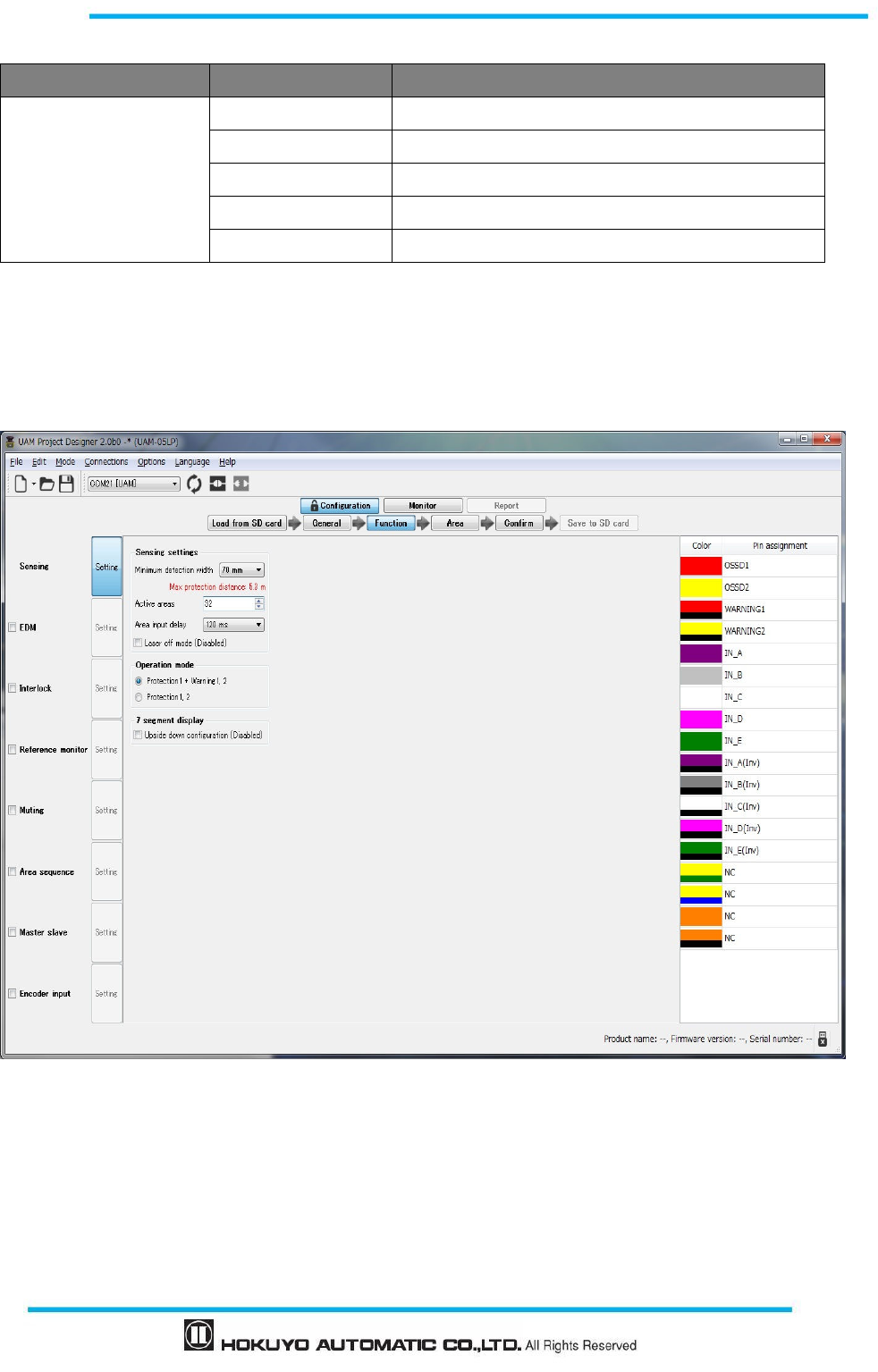
95
Document No: C-61-00003-3
Table 7-11 General
Tab Item Description
General
Product identity Enter ID for UAM (Size limit : 64 characters)
User name Enter User name (Size limit : 50 characters)
IP address Set the IP address
Subnet mask Set subnet mask address
Default gateway Set the default gateway address
C) Functions
UAM functions and related parameters can be selected for configuration. See Table 7-12 for details. Setting
becomes valid when the function is checked displaying the configurable parameters. Sensing is the basic
setting of the sensor therefore it has no check box.
Figure 7-31 Function
Depending on the selected function, active area count and cable pin assignment are automatically
changed. For functions that cannot be used simultaneously, selection of one will disable the other changing
its color to gray. If selecting a function affects the other, its background is changed to yellow. Confirm the
setting of these functions and make corrections if necessary.
Table 7-12 Function

Document No: C-61-00003-3
96
Tab
Item Description
Function
Sensing
Check to enable the sensing function
Min detection width
*
1
(mm) 30, 40, 50, 70, 150
Active areas
*
2
: Area 1 to Area 32
Area input delay :30ms (Default), 120ms, 270ms, 1s, 2s
Operation mode : Protection 1 + Warning 1/2, Protection 1, 2
Laser off mode: Disable (Default), Enable
7-Segment display upside down configuration: Disable (Default),
Enable
EDM
Check to enable the EDM function
On delay(ms): 90 (Default), 120, 300
Off delay(ms): 300 (Default), 330, 360
* In dual protection mode, EDM1 and EDM2 can be configured
independently.
Interlock
Check to enable the Interlock function
Start/Restart mode: Manual/Automatic, Manual/Manual
Delay(s): 1(Default) to 6
* In dual protection mode, interlock can be independently configured
for protection zone 1 and protection zone 2.
Reference monitor
Check to enable the Reference monitor function
Tolerance(mm): 100 (Default) to 10000
Response time : 1s or Operating area response time
Muting
Check to enable the Muting function
Muting input sequence:
Protection zone 1:
Muting 1 Muting 2 (Default),
Muting 2 Muting 1
Protection zone 2:
Muting 3 Muting 4 (Default),
Muting 4 Muting 3Time interval between inputs(s): 1(Default),
3, 5, 10
Max. muting period(min): 1(Default), 6, 12 and Unlimited
Max. override period(min): 1(Default), 6,12
* In dual protection mode, muting can be independently configured for
protection zone 1 and protection zone 2.
Area sequence*
3
Check to enable the Area sequence function
The check box of the area sequence possible area will be valid
The check box for all area will be valid
Master Slave
Check to enable Master Slave function
Current device*
4
: Master, (Default) Slave1, Slave2, Slave3
Slave count: 1 (Default) to 3 (For Master only)
Use own OSSD outputs (For slave only)
Encoder Input
Check to enable the Encoder Input function
Error tolerance: 0 to 80 %
Encoder pulse 1: 50 to 1000 (count/cm)
Encoder pulse 2: 50 to 1000 (count/cm)
Select patterns: Each pattern can be selected from Not Use, Use as
Static input and Use as Encoder input.

97
Document No: C-61-00003-3
Detailed area setting for each pattern.
For the encoder input set speed division count and area for each speed
range. It is not possible to select same area for two different speeds.
For static input, select the area and enable or disable speed monitoring.
If speed monitoring is enabled it is necessary to provide the speed
range.
*
1:
The minimum width of detectable objects. Detection is not possible if configured width is more than the
object intended to be detected.
Default value of minimum width changes depending on the type of selected application. Refer to section
4.11 for the selected values.
*
2:
Set the number of areas to be used. Area count depends on the selected function and adjusted
automatically.
Default value of active areas changes depending on the type of selected application. Refer to section 4.11
for the selected values.
*
3:
For each area, specify one or more area during area sequence.
*4: An error will occur if the UAM with same ID is connected to the currently operating master slave
system.
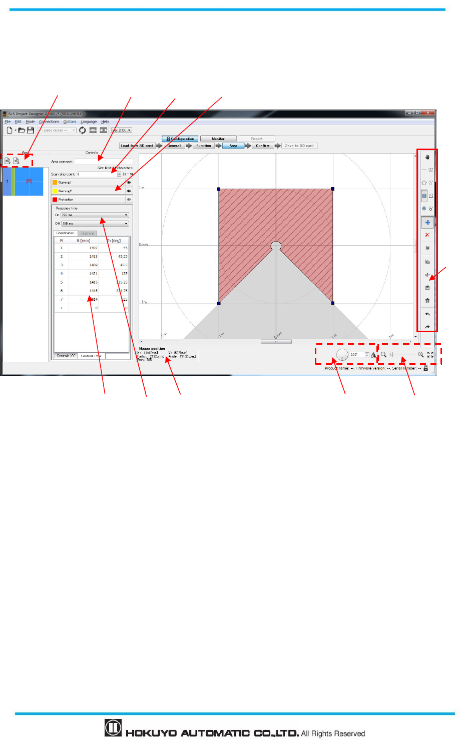
Document No: C-61-00003-3
98
D) Area
User can configure and edit area shapes. Details of each component are explained below.
Figure 7-32 Area configuration tab
<Area>
○
1Area Preview
It displays the shape of each area. It is possible to edit the area when the background of the area preview is
green. The area which is possible to edit is displayed in the area screen. Number on the left of area preview
represents the area number. While changing area setting, the line color will change to green.
<Control>
②Area Comment
Brief explanation of each area can be entered (size limit is 64 characters).
③Response Time (ON/OFF)
Response time of each area can be set.
○
4 Zone Selection
Configuration of respective zone is possible when it is selected.
○
5 Point coordinate
Displays the coordinates of configured points in the zone. They can be also edited directly.
○
6 Area Display
⑧
⑨
⑦
⑤
⑥
②
①
③
④
⑩
⑪
⑫
99
Document No: C-61-00003-3
Shapes of all the areas are displayed.
○
7 Mouse position
If the cursor is placed on the configured area, sensor coordinate represented by the mouse pointer is
displayed. Table 7-13 explains in detail.
○
8 Zoom In, Zoom Out tool
Adjust the area display screen ratio. Table 7-14 explains each icon.
○
9 Drawing tools bar
Tool icons for configuring the area shape. Table 7-15 explains each icon.
⑩ Tool for rotating and reversing the display
Tool icon to rotate and reverse the area and measurement data
⑪ Scan skip count
Scan skip count can be individually set for each area. (Refer to section 3.19 Scan Skip Function)
⑫ XML File Tool
There is an icon to import and export the XML file containing the area information. Icon details are
explained in Table 7-17.
Table 7-13 Display of mouse information
Display Description
X (mm)
Displays the mouse position of x
-
coordinates.
Y (mm)
Displays the mouse position of y
-
coordinates.
Radius (mm)
Displays the d
istan
ce from the origin to the po
sition of the mouse
.
Angle (deg
)
Displays the d
istance from the smallest angle to th
e position of mouse
.
Step
Display
s
the step value of mouse position.
Table 7-14 Display adjust icons
Icon Function
Zoom out the main view screen. Same operation can be done by scrolling mouse down.
Move the cursor left for zoom out and right for zoom in.
Zoom in the main view screen. Same operation can be done by scrolling mouse up.
Reset the view to fit the window.
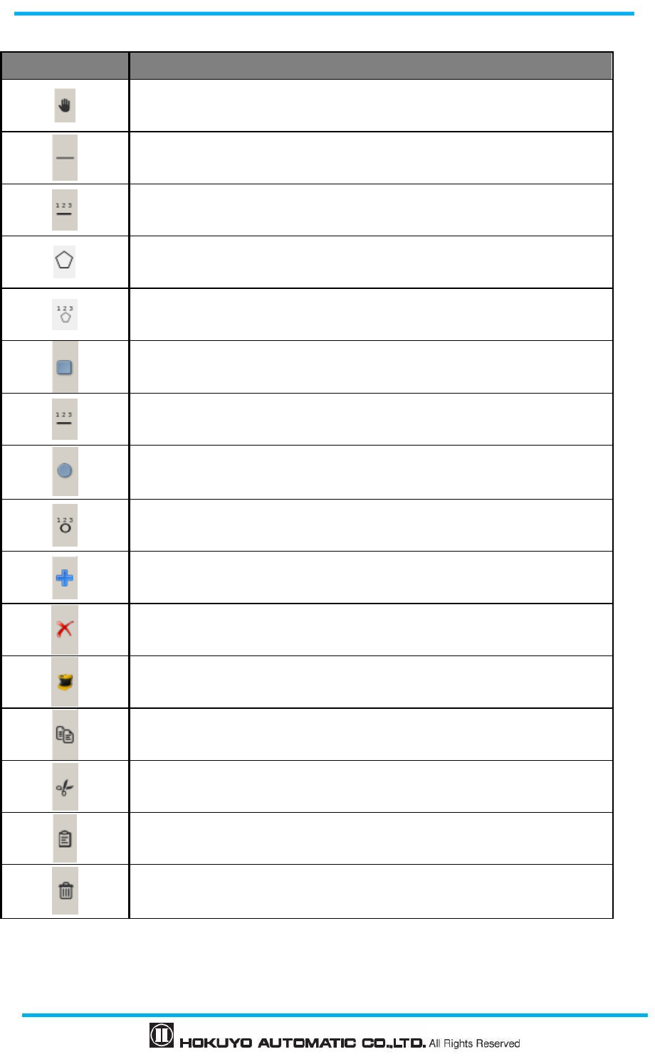
Document No: C-61-00003-3
100
Table 7-15 Drawing assistance icons
Icon Function
Move the configured area
When line segment is drawn by moving the mouse, a triangular shape is
drawn by connecting the two points of the line and the origin.
When coordinates of start and end points of a line are specified numerically, a
triangular shape is drawn by connecting these points with the origin.
When multiple points are selected with mouse click, a polygon is generated
by connecting these lines and the origin
When coordinates of multiple points are specified, a polygon is generated by
connecting these lines and the origin.
When square shape is drawn by moving the mouse, a shape connecting its
four edges and the origin is drawn.
When four coordinates of square shape are numerically specified, a shape
connecting these points and the origin is drawn
When circular shape is drawn by moving the mouse, a shape connecting the
arc of the circle with the origin is drawn.
When center, radius and starting and end point of the arc are numerically
specified, a shape connecting the arc of the circle with the origin is drawn.
Specified shape is added to the area.
Specified shape is removed from the area.
Configure the zone by automatic teaching function
Copy the selected area
Cut the selected area
Paste the area previously copied or cut.
Delete the selected area.
101
Document No: C-61-00003-3
Table 7-16 Rotate and reverse icon
Icon Function
It will undo the previous operation
It will redo the last operation
Rotate the area and measurement data display window
Reverse the area and measurement data display (left to right or right to left)
Table 7-17 XML file icon
Icon Function
Imports area details from XML file (Check the help menu for details on XML file
format)
Exports area details to XML file.
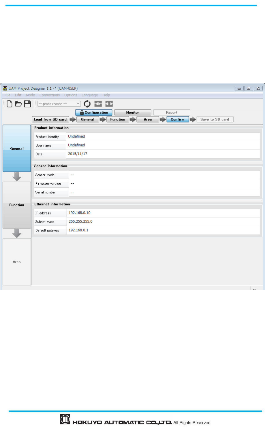
Document No: C-61-00003-3
102
E) Confirm
After completing all the configurations, they can be reviewed by clicking the confirm button followed by
the steps shown in Figure 7-33(a) to (c). Return back to the respective tab if correction is necessary.
Click the “Transmit to sensor” button if configuration has no error to write it into UAM if it is connected or
“Save to SD card” button to save the setting file into the SD card memory when UAM is not connected.
Figure 7-33(a) General
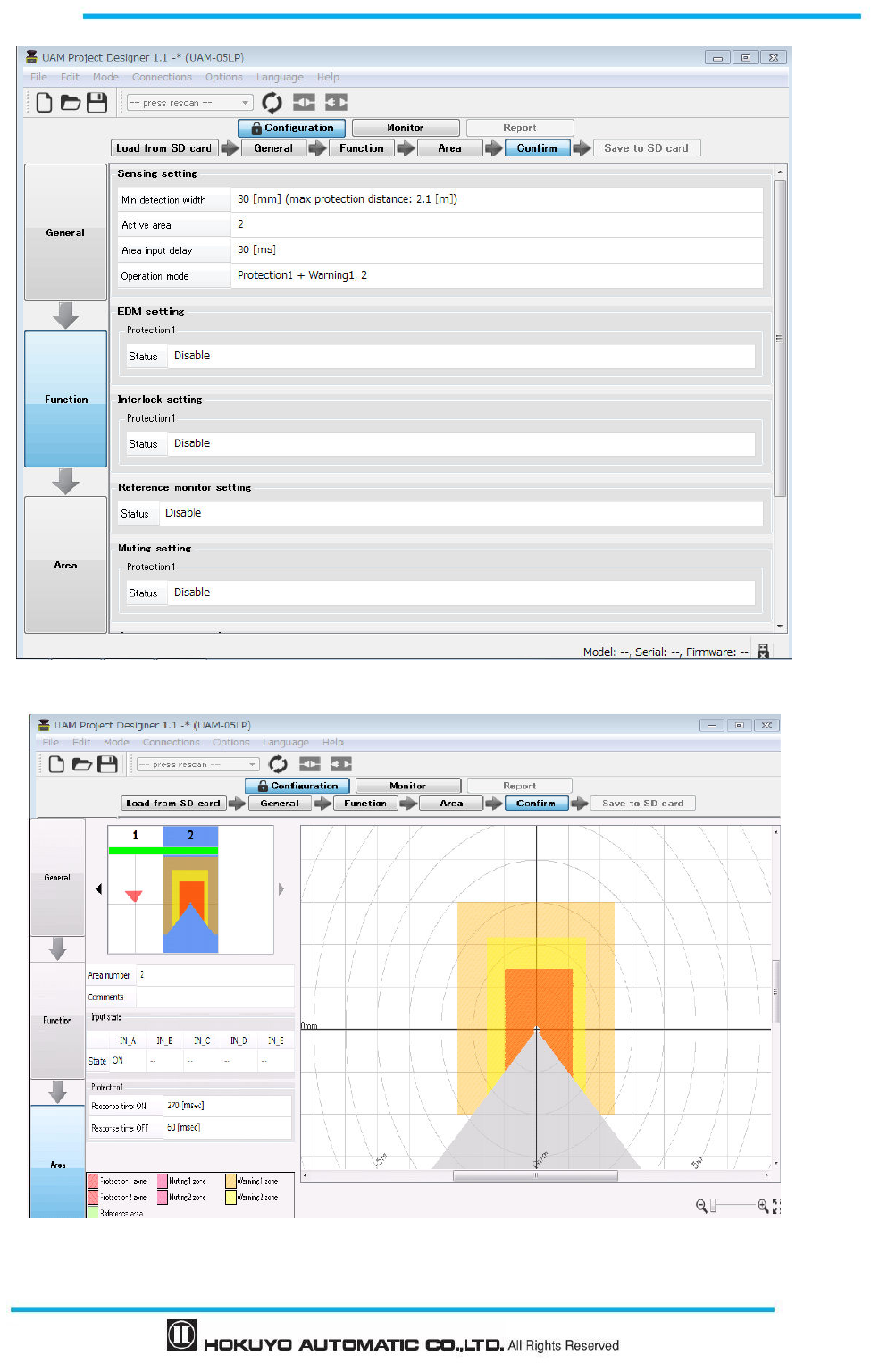
103
Document No: C-61-00003-3
Figure 7-33(b) Function
Figure7- 33(c) Area
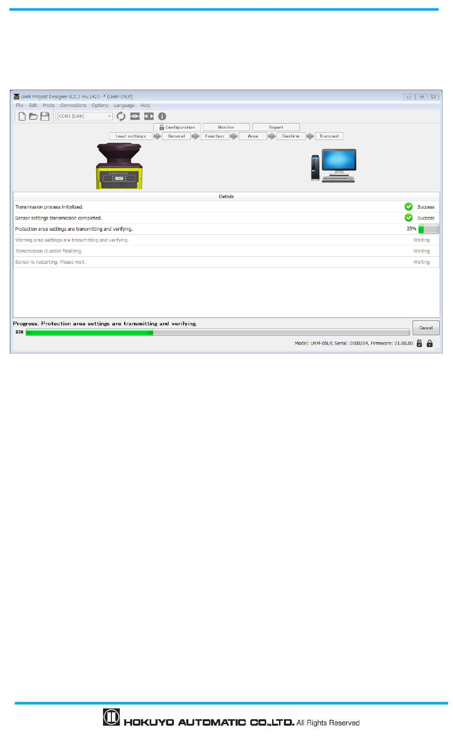
Document No: C-61-00003-3
104
F) Transmit to sensor/ Save to SD card
Click “Transmit to sensor” button if error is not found during confirmation to transmit the configuration to
the UAM. If device is not connected, click “Save to SD card” button to save the setting file into the SD card
memory.
Figure 7-34 Transmit window
Depending upon the computer’s performance it may take few minutes to transfer the configuration. When
transferring process is completed, UAM will restart automatically.
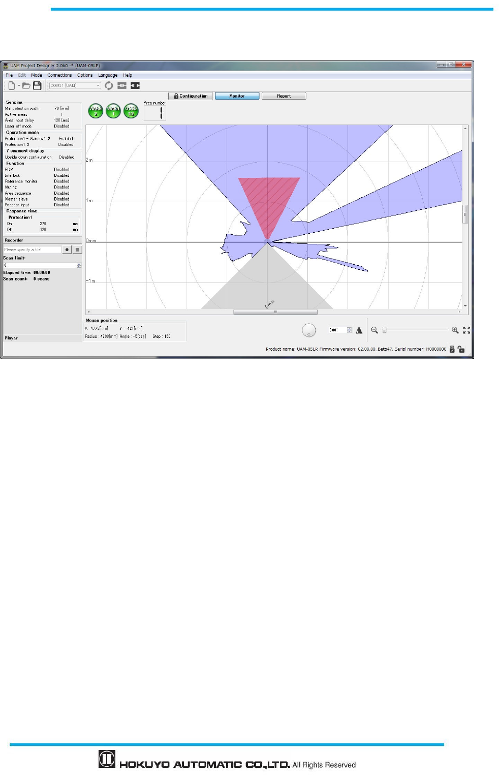
105
Document No: C-61-00003-3
7.9.2 Monitor tab
User can monitor the detection state of the UAM by selecting the monitor tab.
Figure 7-35. Monitor tab
7.9.3 Report tab
Report tab is only functional when the UAM is connected to the application. There are 3 types of reports:
Project report, Error report and Detection Log report. Project report includes the UAM’s configurations.
Error report includes error recorded during the operation and past errors. Detection Log reports displays the
history of object detected in the protection zone. For detail on report tab items refer to Table 7-18. User can
save reports in PDF format by clicking the [Output PDF] button. When clear button is clicked all the records
are deleted from the sensor. When refresh button is clicked latest information are updated from the sensor.
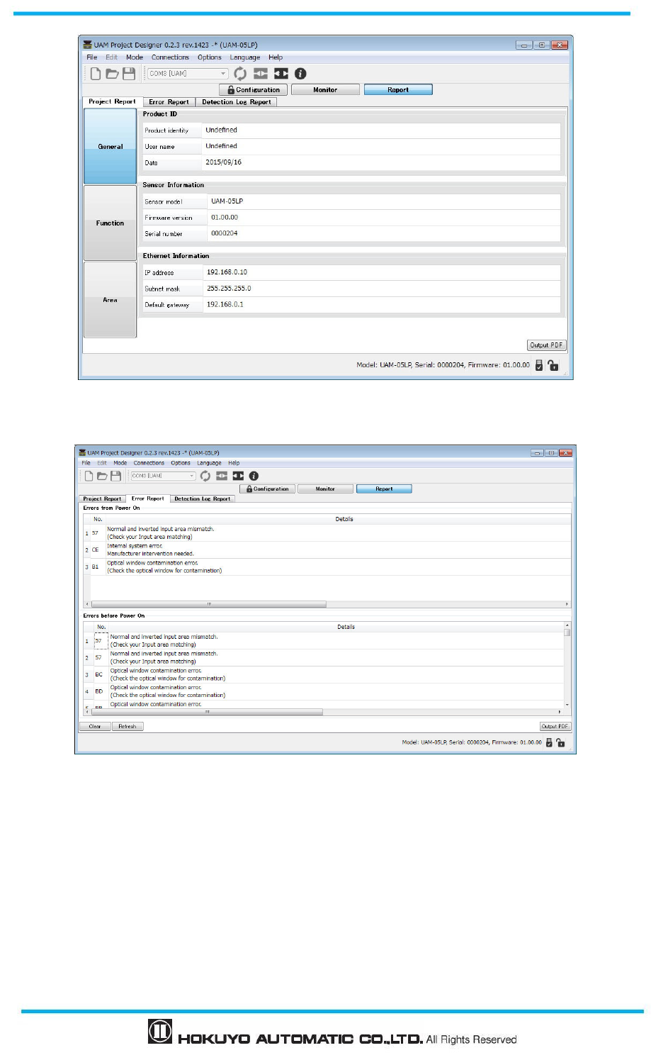
Document No: C-61-00003-3
106
Figure 7-36(a) Project report tab
Figure 7-36(b) Error report tab
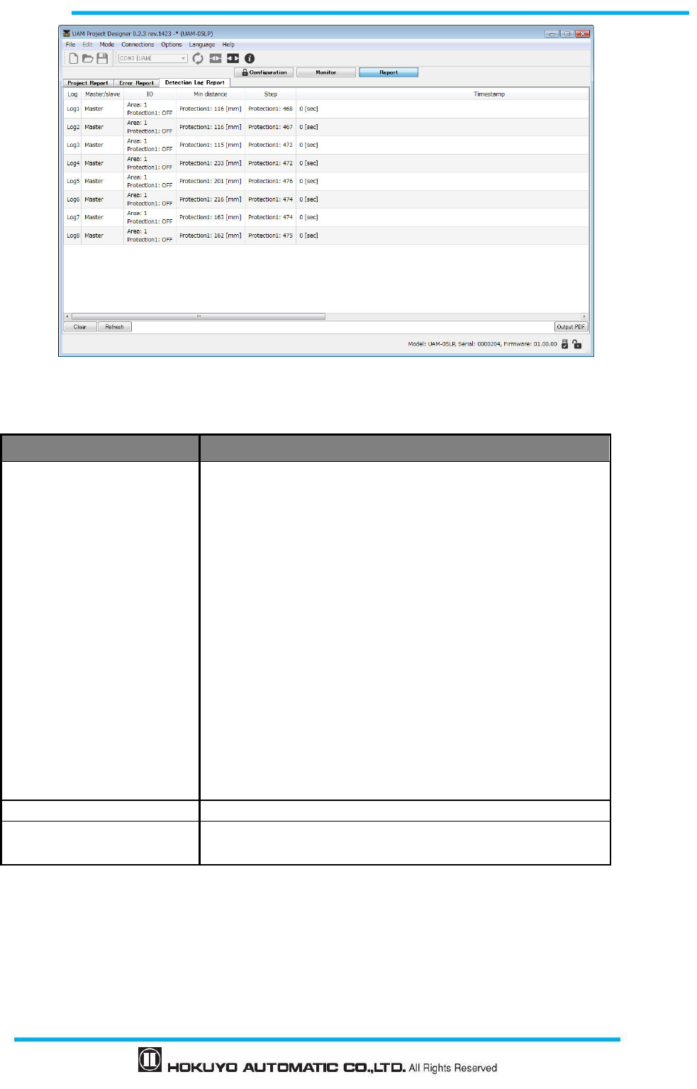
107
Document No: C-61-00003-3
Figure 7-36(c) Detection log report tab
Table 7-18 Report display items
Report Items show in report
Project
Product identity
User name
Date
Sensor information
Ethernet information
Sensing
Operation mode
EDM
Interlock
Reference monitor
Muting
Area sequence
Encoder input
Static area input
Encoder area input
Master salve
Area information
Error Error report includes error recorded during operation.
Detection log Detection status during the operation (Area, Minimum distance,
steps, time stamp)
* Report is in PDF format. To view the report, Adobe Reader
®
or any equivalent application software is
required. Free version of Adobe Reader
®
can be downloaded from the website:
http://www.adobe.com.
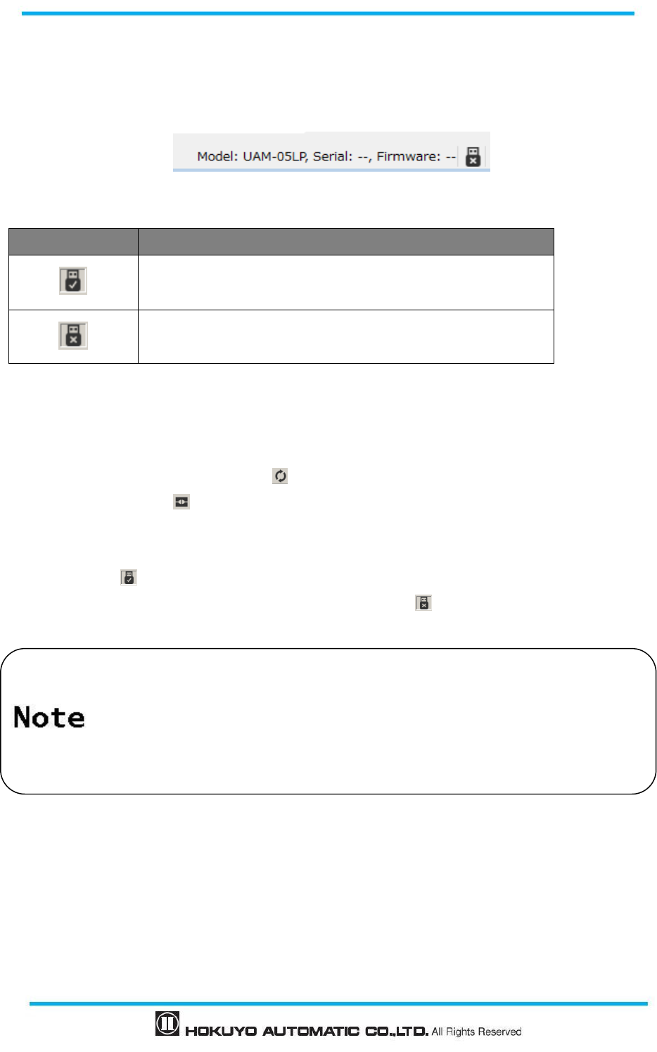
Document No: C-61-00003-3
108
7.10 Status bar
This section displays the model, serial number, firmware version of the connected sensor. Icons on the right
show connection state. Table 7-19 explains the meaning of each icon.
Table 7-19 Status bar icon
Icon Description
Indicates the connected state with UAM.
Indicates the disconnected state with UAM.
7.11 Connecting UAM with PC
a) Supply the power to UAM and connect with PC through USB cable.
b) When connection is established application will automatically detect the UAM and displays its COM
port. If it is not displayed, click rescan icon on the toolbar to refresh the COM port.
c) Click connect device icon on the tool bar and enter the password when dialog appears (refer to
section 7.12).
d) Connection status is shown on the information tab. When UAM is successfully connected, icon changes
to connected
state.
e) When the UAM is disconnected, icon changes to disconnected state.
Do not use the USB hub.
When UAM is not detected even if it is connected to the PC, click the port refresh
button.
When an additional UAM is connected on the same PC, click the port refresh
button.
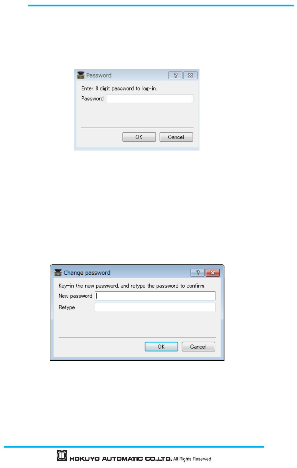
109
Document No: C-61-00003-3
7.12 Password
Configuration of UAM is password protected for preventing unauthorized access. User should enter the
password before proceeding to configuration screen. When the window as shown in the figure 7-37 is
displayed, enter the password and click ok. Default password is 12345678.
Figure 7-37 Password
7.12.1 Changing the password
User can change the password by performing the following steps:
Click the Options on the menu bar.
Click the Change Password.
Window as shown in figure 7-38 will be displayed.
Enter the new password and retype the new password for confirmation. The new password should
consist of 8 numerical digits.
Figure 7-38 Password change
Click OK to complete the process of changing the password.
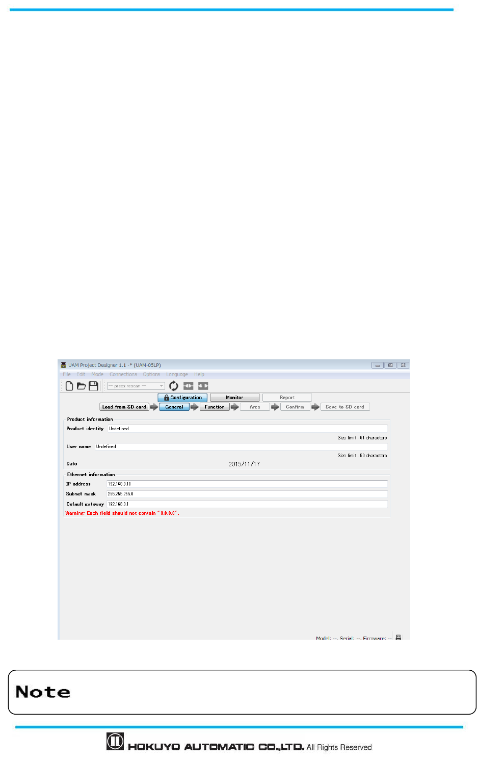
Document No: C-61-00003-3
110
7.12.2 Reclaim the forgotten password
When the password is forgotten, follow the steps below to reclaim the password.
a) Click the File of the menu bar.
b) Click the Save As or press Ctrl + S and save the project at a preferred location. Project will be saved in the
file [*****.huc].
c) Send this file [****.huc] file to the nearest office or representative listed on this manual to reclaim the
forgotten password.
7.13 Configuration mode
Click on the configuration tab to configure the setting of UAM. The configuration of UAM is password
protected to prevent the unauthorized access. User is required to log-in with the password to proceed with
the configuration. Refer to chapter 7.12 for details on password. Follow the steps below for configuration.
a) Confirm that UAM and PC is connected (refer to section 7.11). Connect it if it is not. Even if UAM is not
connected, user can configure the settings but cannot the transfer them to UAM.
b) Click the “Configuration” tab or on the menu click “Mode” and select “Configuration”
c) Enter the product identity and user name in the General configuration tab, Enter the value in the Ethernet
information to change the IP setting. This information is also shown on UAM Project Designer’s report.
Refer to chapter 7.9.3 for details on report display.
Figure 7-39 General
OSSD remains in OFF state when UAM is in configuration mode
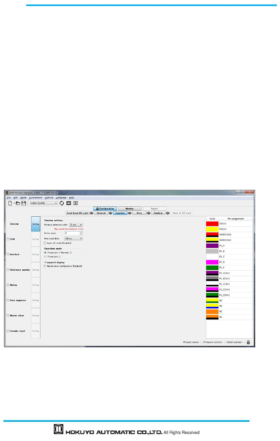
111
Document No: C-61-00003-3
7.14 Function configuration
User can configure various functions of the UAM through UAM project designer. Click on the [Function]
tab to display the list of configurable functions (Figure 7-40). Put a check mark to activate the corresponding
function (refer to section 7.9.1 for detail). List of configurable functions are shown below. There are some
functions which cannot be used simultaneously *1. In such case, if one function is selected the other will be
displayed in gray and cannot be selected. Also, maximum configurable area will change depending on the
selected function. Confirm the pin assignment setting as it automatically changes according to the selected
function.
Sensing *2
EDM
Interlock
Reference Monitor
Muting
Area Sequence
Master Slave
Encoder Input
Figure 7-40 Function information
*
1
:
Muting and encoder, Muting and Interlock, Muting and Master slave functions cannot be configured simultaneously.
Encoder input cannot be configured when dual protection mode is selected.
*
2:
Sensing is the basic setting of the sensor therefore there is no check box.
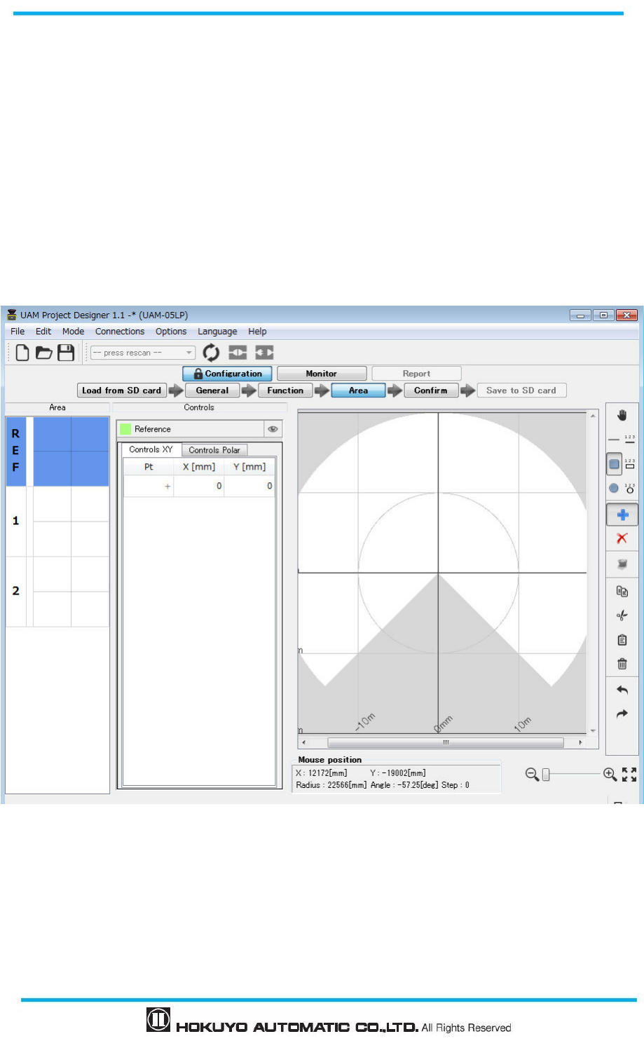
Document No: C-61-00003-3
112
7.15 Area configuration
When Area tab is clicked, area configuration screen will be displayed as shown in figure 7-41.
There exist two types of regions, one where configuration of protection and warning zones are possible and
the other where it is not. Range shown in the white represents the region where it is possible to configure the
protection zone. Range shown in the light gray is the region where configuration of warning zone is possible.
Range shown in the dark gray (beyond 20m from the origin) shows the region where both protection and
warning zones cannot be configured. It is possible to configure warning zone inside the protection zone
configurable region. Range of protection zone depends on the minimum detection width and changes
automatically when it is selected on the sensing setting panel. Configure the number of protection and
warning zones activated in the sensing panel.
Click “Area” button to switch to area configuration panel.
Figure 7-41 Area configuration widow
Select the area number from area preview panel and click the indented zone among Warning1,
Warnign2 and Protection for configuration. Buttons for configuring the Muting and Reference
monitoring zone will be displayed when the corresponding functions are enabled. Reference area
preview marked by “REF” is visible when reference function is enabled.
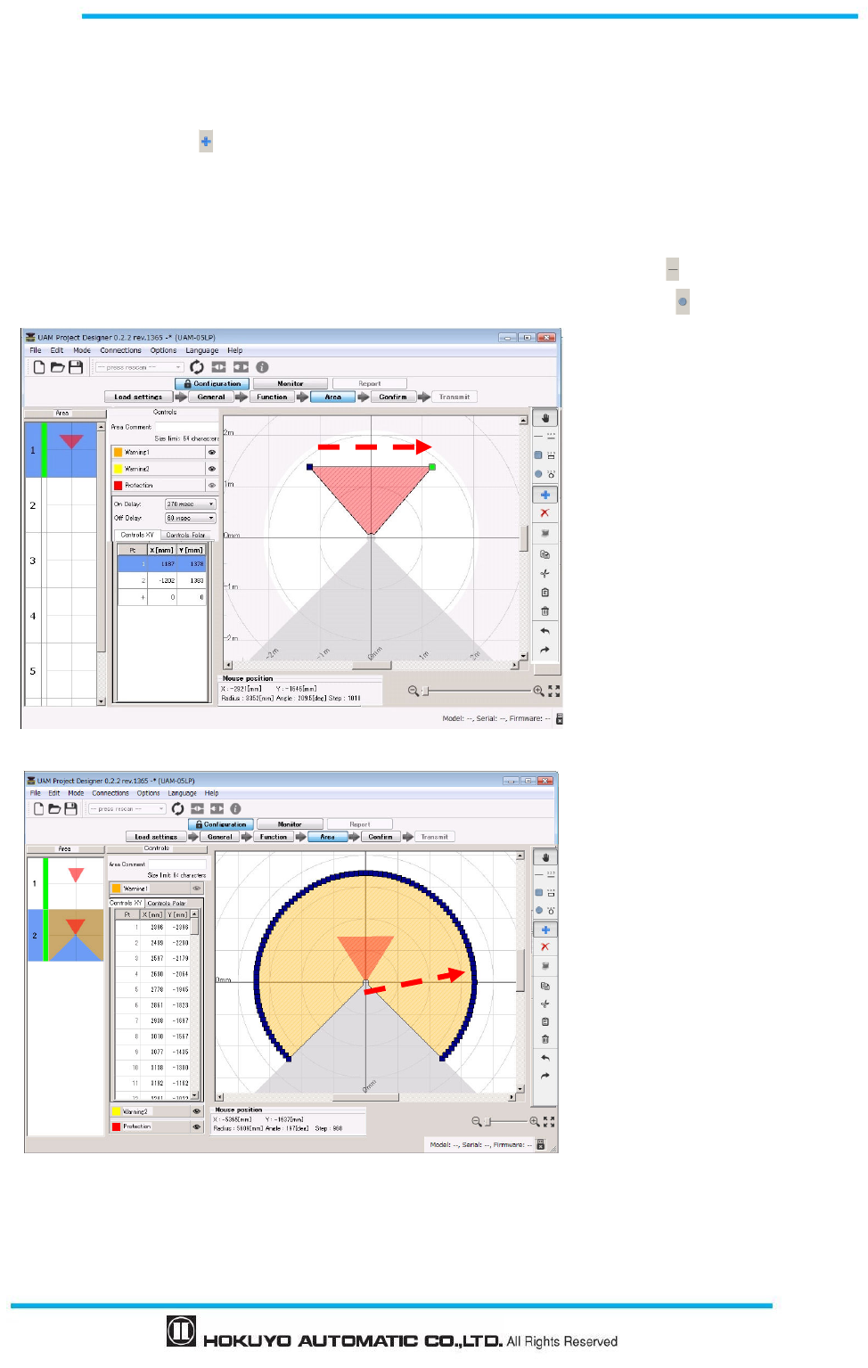
113
Document No: C-61-00003-3
7.15.1 Area configuration by drawing tools
Zones can be configured using the drawing tools on the UAM project designer. Refer to Table 7-15 for the
details.
Click on the Add button.
Select the drawing shape.
Move the cursor inside the setting possible region and draw the shape by drag and drop operation.
While drawing it is possible to switch the shapes to draw areas with combination of shapes.
Figure 7-42 (a) shows an example of protection zone set by the selecting the line
Figure 7-42 (b) shows an example of warning zone1 set by the selecting the circle
Figure 7-42 (a) Zone configuration example 1
Figure 7-42 (b) Zone configuration example 2
1
11
1
2
22
2
When a straight line is drawn
from point 1→ point 2, a
triangular shape is formed by
connecting these two lines with
origin. Coordinates of point 1
and point 2 are also displayed.
When mouse is dragged from
point 1 → point 2, a circular shape
with origin at point1 is generated.
Circular shape cannot be formed
if point is dragged beyond the
allowed region. Coordinates of
each point are also displayed on
the coordinate panel. Points are
displayed at every 2.5°.
1
11
1
2
22
2
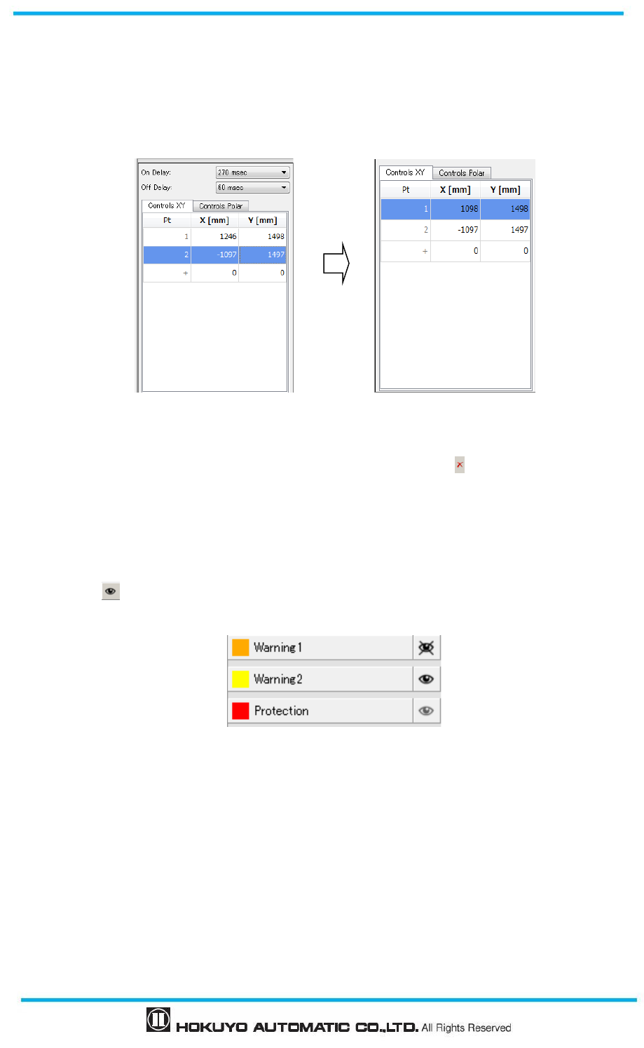
Document No: C-61-00003-3
114
Coordinates of configured points where the numeric values are shown can be edited directly by double
clicking on the cell. It is also possible to switch between XY coordinates and polar coordinates. Further,
a new point can be added by clicking on the + button on the Pt. column.
* Use backspace key to delete a single coordinate point on the display panel.
.
Figure 7-43 Coordinate example
To delete the parts of the configured zone, click the delete button , then drag-drop the cursor to
specify the zone to delete.
For configuring the other zones, select the respective zone and repeat the above steps.
Confirm that each zone is configured correctly.
If overlapping of shapes disturbs in creating or confirming the zone, visibility can be toggled by
clicking the button.
Figure 7-44 Switching between visible and invisible mode
← Invisible
← Visible
← Visible
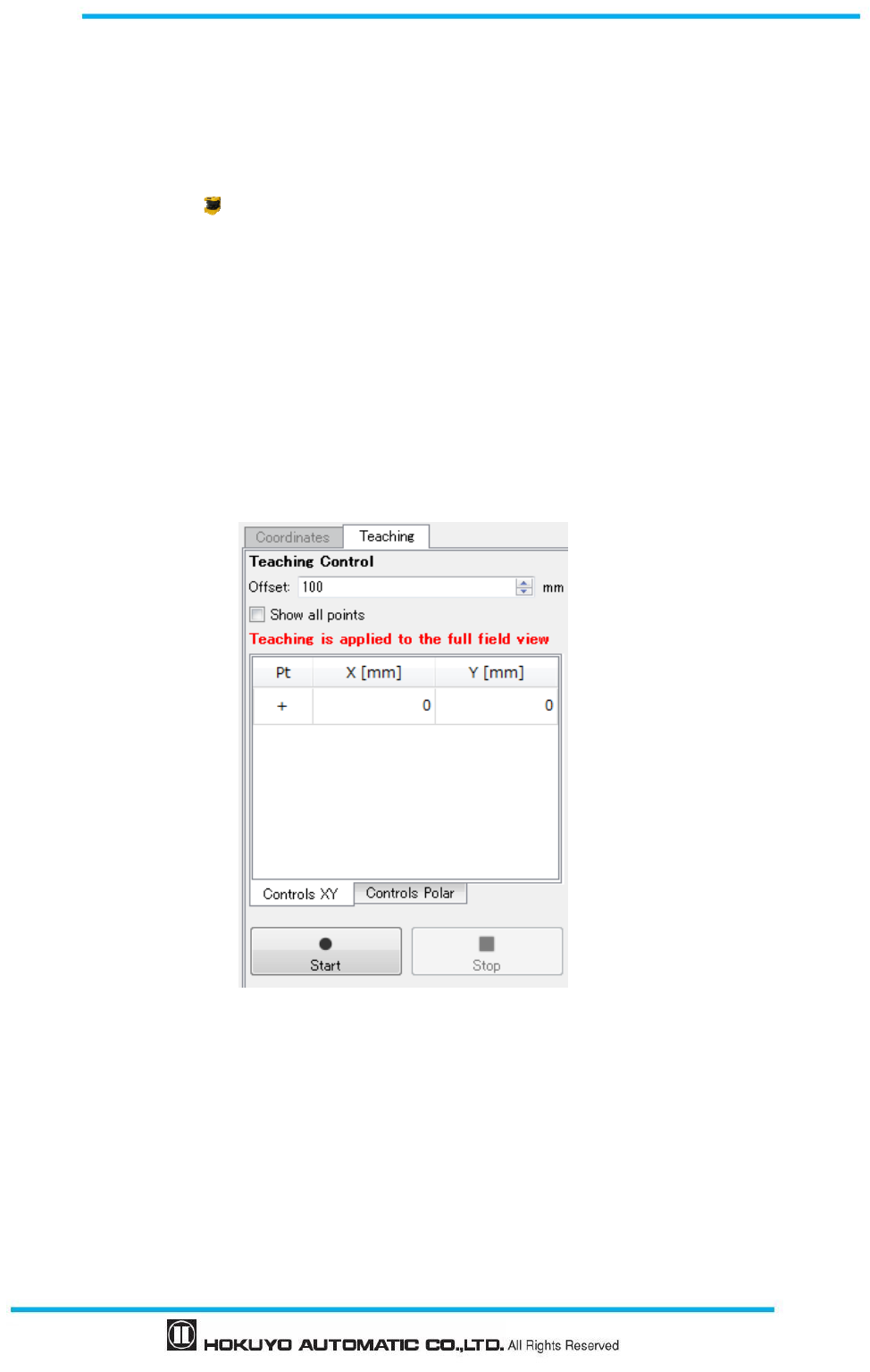
115
Document No: C-61-00003-3
7.15.2 Area configuration by teaching function
Automatic zone configuration by referring the boundary can be done by using the UAM’s Teaching
function. This function is useful when user needs to configure complex zone or would like to reduce the time
for zone configuration. Steps below show the configuration procedures using the teaching function.
Ensure the UAM is connected with the PC.
Click on the Teaching button.
Enter the offset to be applied between the zone and the background (Max offset can be up to maximum
measurement distance).
Click the “Start” button (Figure 7-45) to start recording the background data. Recording will continue
until the stop button is clicked
Further, to use all sensor measurement points for the teaching function, check the [Show all points] and
press [Start] button.
Figure 7-45 Teaching setting
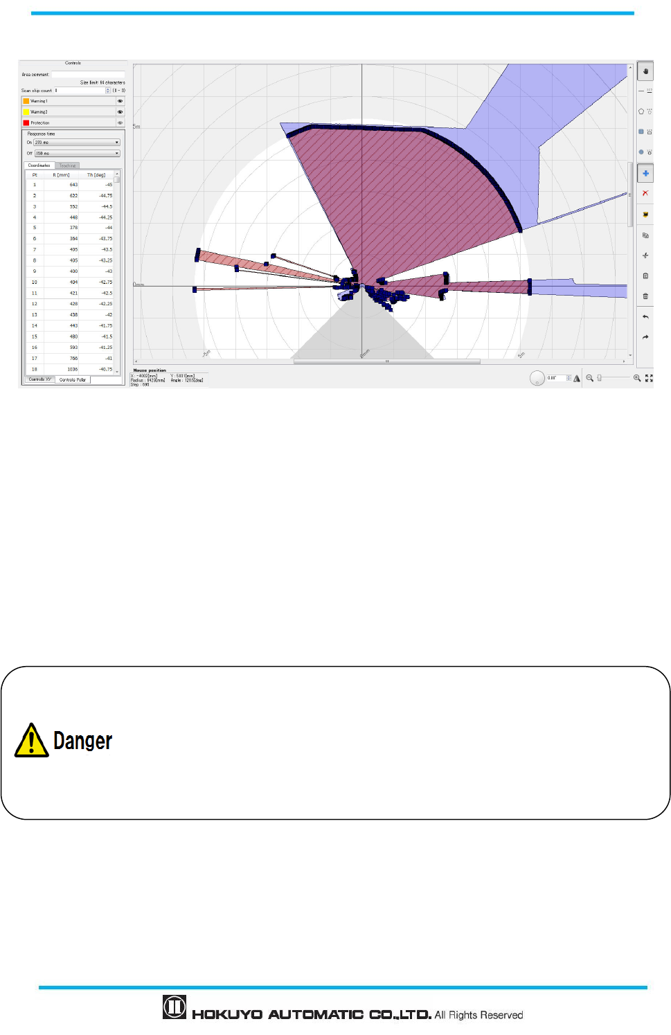
Document No: C-61-00003-3
116
Figure 7-46 Area configured by teaching
When the stop button is clicked, an area is generated by the smallest data recorded. Configured area
will resemble the UAM’s background. (Figure 7-46). When configuring the protection zone, if the
background is not within the maximum detection distance it is set to maximum detection distance of
UAM. In case of warning area, if there is no background within 20m from UAM it will be set to 20m.
After the area is created automatically it can be edited using the drawing tools.
It is also possible to specify the region for generating the area by teaching function. Use the area tools
for this purpose. If specified region does not have any background, area will be generated at the
maximum distance of the specified region.
While using the teaching function, user should confirm that
the configured zone
meets the safety requirement.
Distance from area to the background should be in the range of 100mm to 700mm.
If the distance exceeds the above mentioned range, there may be unprotected
hazardous area that could lead to critical injury or death.
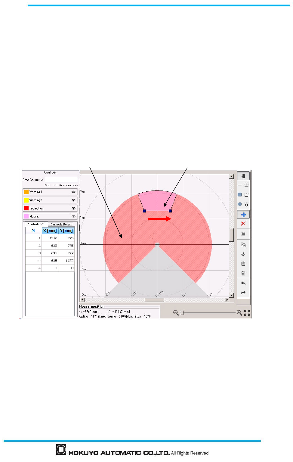
117
Document No: C-61-00003-3
7.15.3 Muting configuration
Muting function temporary suspends the safety functions of UAM when required conditions are fulfilled.
Follow the steps below to configure muting function.
Confirm that muting function is enabled in the function tab.
Before configuring the muting zone it is necessary to configure the protection zone. Configure the
protection zone if it is not yet configured.
When muting button is clicked, muting configuration screen is displayed. Drag and drop the mouse
over the protection zone to configure the muting region inside it. Protection zone is displayed in red
and the muting region is displayed in pink.
Figure 7-47 and 7-48 shows an example of the muting zone configuration. Region in pink
represents the muting zone.
Confirm that the muting configuration is correct.
Figure 7-47 Muting zone configuration example 1
Muting zone configuration example as straight line is drawn from point 1 to point 2
Protection zone Muting zone
1
11
1
2
22
2
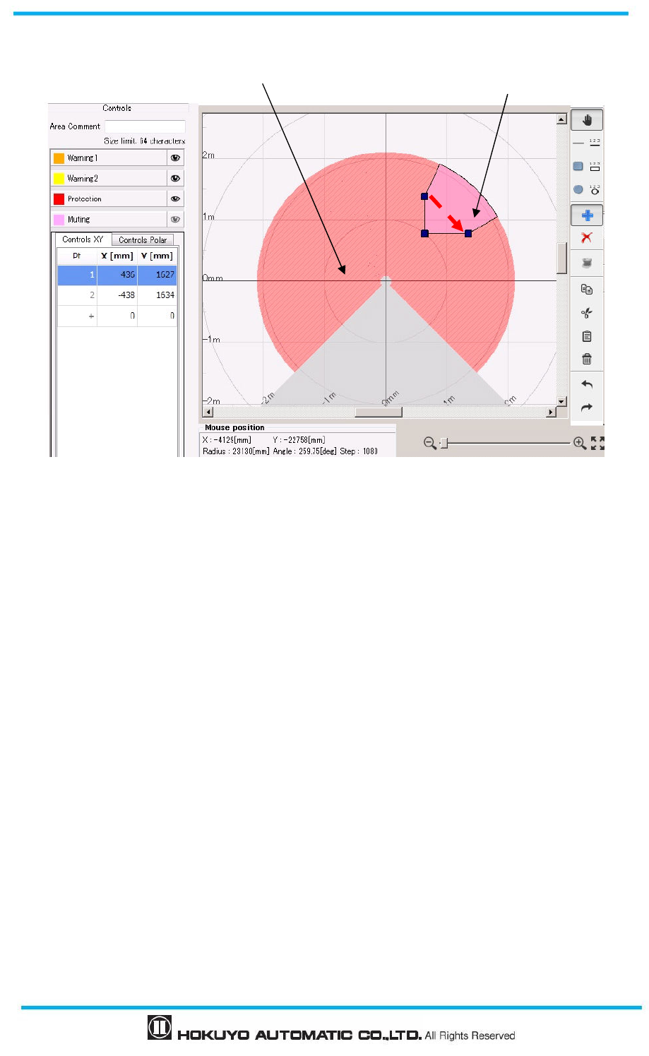
Document No: C-61-00003-3
118
Figure 7-48 Muting zone configuration example 2
Muting zone configuration example as square is drawn from point 1 to point 2
7.15.4 Reference region configuration
Follow the steps below to configure reference region.
Ensure the UAM is firmly mounted at its location.
Ensure the connection between the UAM and PC.
Click the Function tab and enable the Reference Monitor function and enter the required tolerance
distance (default 100mm).
Click the Area tab.
Main screen displays the configuration for reference region (Figure 7-49). First area on the preview
indicated by “REF” represents the reference area.
Configure the reference region by using the drawing tools. Move the cursor on the drawing panel
and drag and drop to configure the reference. Monitoring region is displayed in green
Protection zone
Muting zone
1
11
1
2
22
2
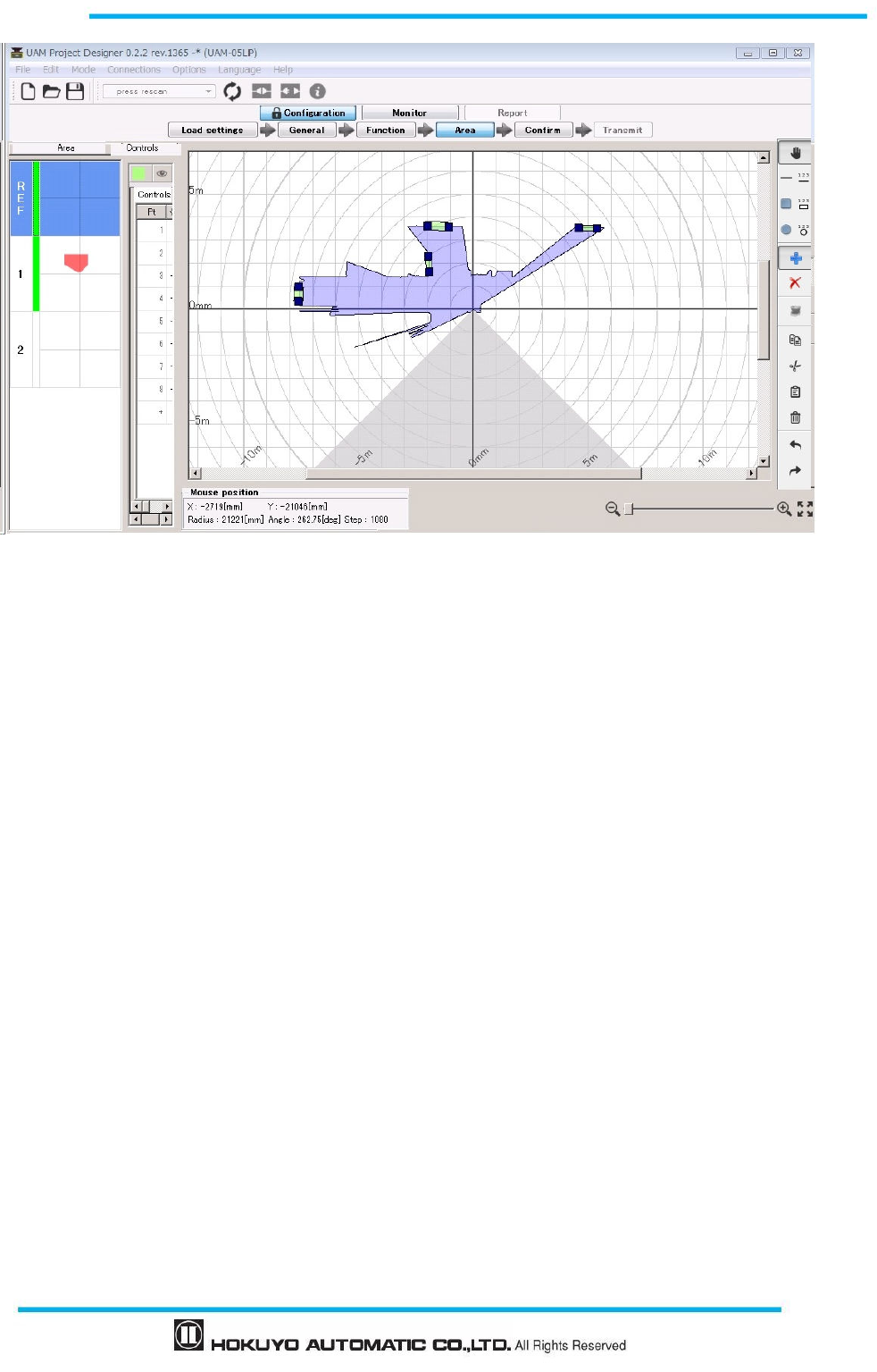
119
Document No: C-61-00003-3
Figure 7-49 Reference region configuration example
For example, to monitor the sensor’s displacement by referring the background, choose the line drawing
tool and draw a line segment over the background by mouse drag and drop. Reference region with the
±tolerance is generated on that location (Figure 7-49).
7.16 Transmit configurations to UAM
When all the configurations are complete, click “Confirm” button to verify the configuration. On the
confirm screen, check general, function and area settings in order. If any correction is required, return to
related tab and reconfigure the setting. On the area confirm screen, click each area preview to confirm all
areas. Transmission is prevented until the green line appears on all the area preview items. When
confirmation is complete, connect the application with UAM if it is not connected and click “Transmit to
sensor” to transmit the configuration. In the disconnected state the configuration can be saved into SD card
memory by clicking on the “Save to SD card” button.
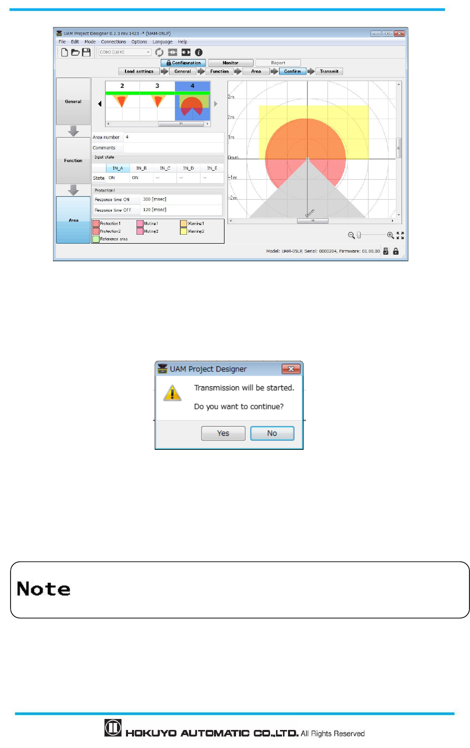
Document No: C-61-00003-3
120
Figure 7-50 Confirm monitor example
When transmit button is clicked verification window appears (Figure 7-51). Click yes to transfer the
configuration to UAM
Figure 7-51 Reference monitor configuration example
It may take few minutes to transfer the settings to UAM. When transfer is completed UAM will restart
automatically. UAM Project Designer will return to start up panel. Click connect button to run the UAM in
monitor mode and verify the operation.
Do not insert SD card while writing the
configuration to UAM through USB
connection. It may cause configuration failure.
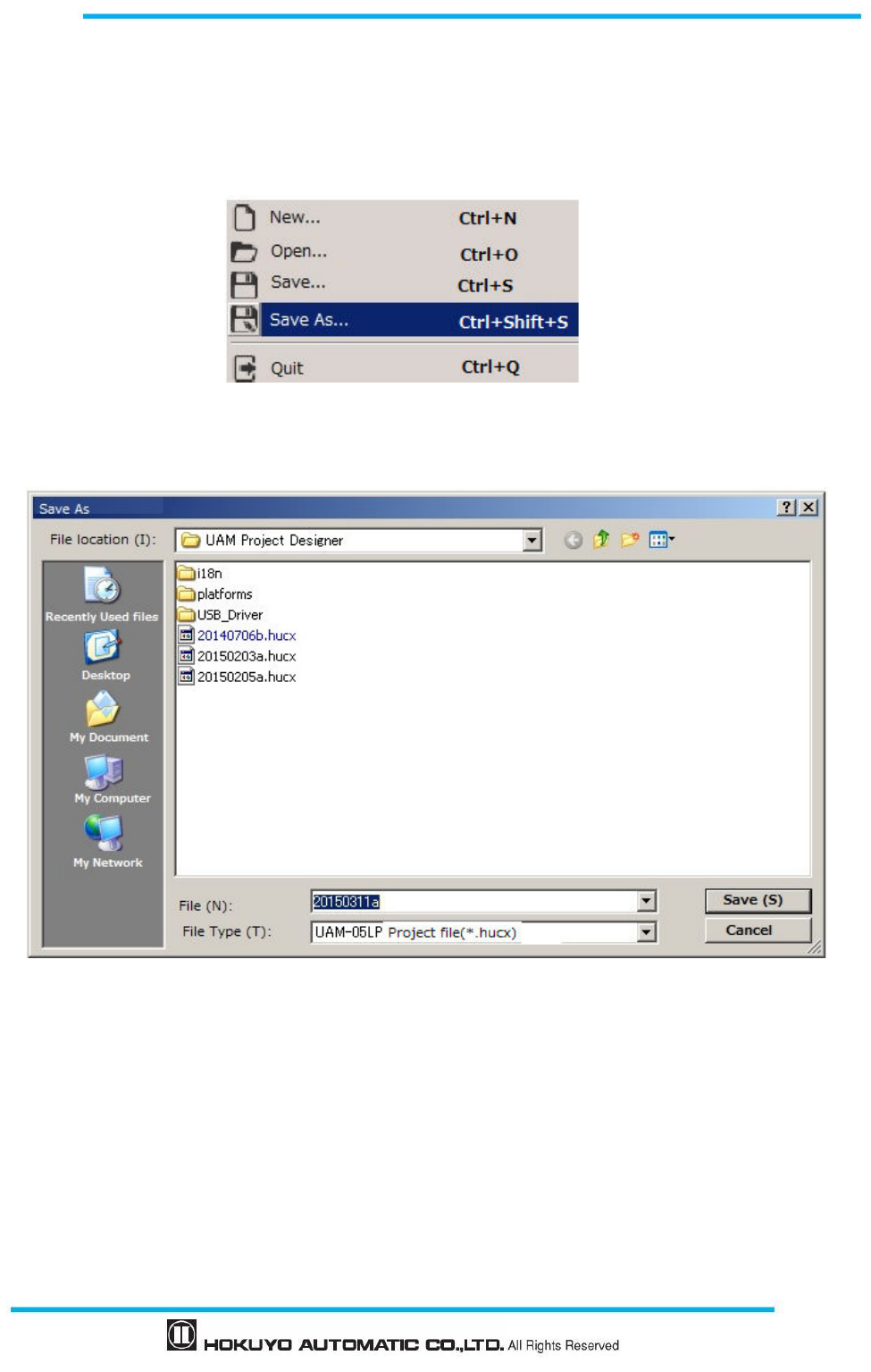
121
Document No: C-61-00003-3
7.17 Save project file
Configured functions and area can be saved into a file as a project. Follow the steps below to save the
project file.
a) Click File from the menu bar.
b) Click Save As. (Figure 7-52)
Figure 7-52 Save project file
c) Enter a file name and click Save button. Change the location of the file if necessary
.
(Figure 7-53)
Figure 7-53 Save project file
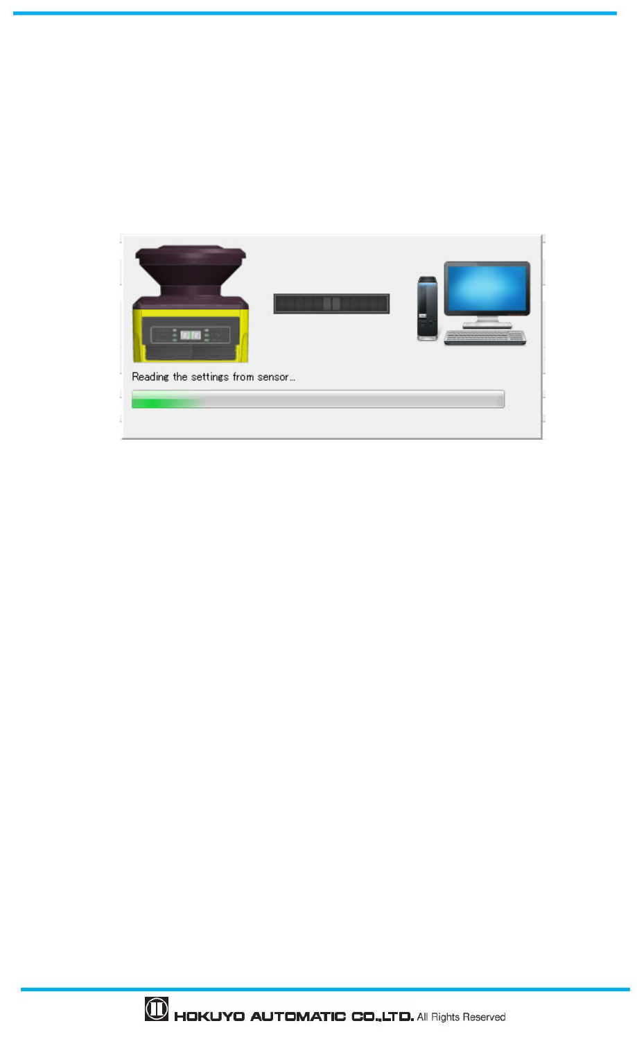
Document No: C-61-00003-3
122
7.18 Read configuration from UAM
User can check the current settings or confirm the configurations of the UAM by performing the following
steps.
a) Confirm the UAM and UAM Project Designer is connected.
b) Select Load settings on the sub panel window. Progress panel will appear (Figure 7-54) showing the
state. If this button is clicked without connecting the UAM a dialog box will appear to read settings
from the SD card (refer to section 7.9.1).
Figure7-54 Reading the configuration of UAM
c) When reading is complete panel will disappear.
d) Confirm the General, Function and Area settings. Modify the settings if necessary and click transmit to
write the configuration to UAM.
7.19 Open project file
User can open UAM project file by performing the following steps.
a) Click File from the menu bar.
b) Click Open
c) Dialog box will appear (Figure 7-55). Select the project file [*****.hucx] to open.
d) Application reads the contents of project. Confirm the General, Function and Area settings. Modify the
settings if necessary and click transmit button to write the configuration to UAM.
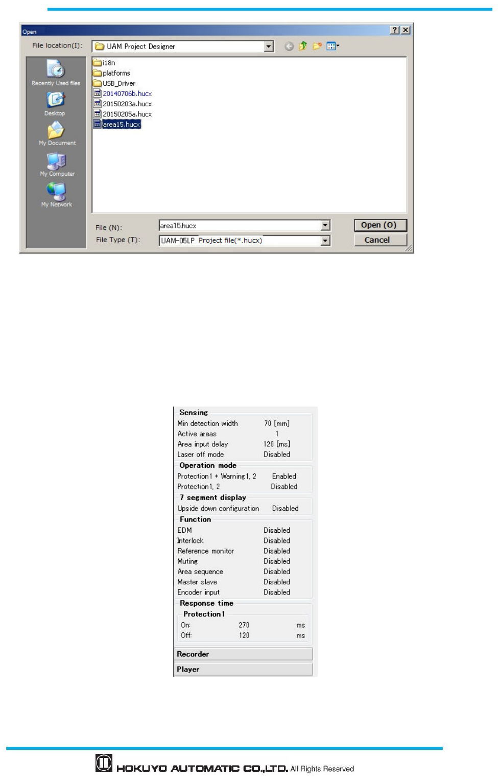
123
Document No: C-61-00003-3
Figure 7-55 Save project file
7.20 Recording the UAM data
Follow the steps below for data recording.
a) Connect UAM with UAM Project Designer.
b) Click the monitor button on sub panel. Application will switch to monitor mode.
c) Click the recorder button.
Figure 7-56 Recorder button
d) Data recording window will appear.
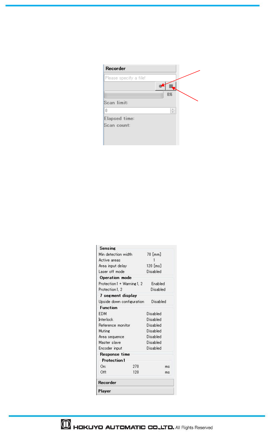
Document No: C-61-00003-3
124
Enter the number of scans in the scan limit field (Figure 7-57) and click the record button. Application
will automatically create the file click save. Change the file name and folder if necessary. Data recording
will start and stops automatically when the specified scan count is completed. Click the stop button to
terminate the recording before reaching the scan count.
Figure 7-57 Data logging window
7.21 Replay the log data
Follow the steps below for re-playing the log data.
1 Confirm that UAM is disconnected with UAM Project Designer. Check disconnect button if is
connected.
2 Click “Monitor” button of sub panel and switch to monitor mode.
3 Click player button.
Figure 7-58 Log player window 1
Record button
Stop button
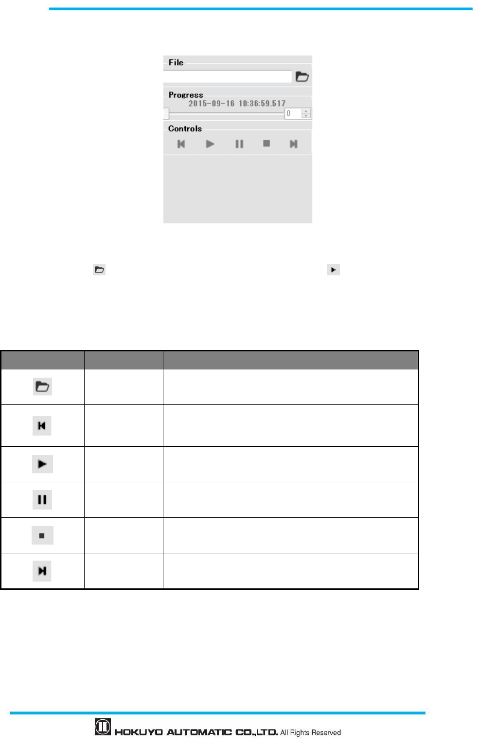
125
Document No: C-61-00003-3
4 Select the log data file for re-playing (Figure 7-59).
Figure 7-59 Log player window 2
Click the open icon to choose the file for re-playing and click the play icon to start viewing the
log data. Move the slider bar to the desired position to view the specific scan data.
Control icons are explained in Table 7-20.
Table 7-20 Control button
Icon Name Description
Open Open and select the log data which you want to play.
First Moves to the initial position of log data.
Play Starts playing the log data.
Pause Pause/ Stops the log data for a while.
Stop Stops the log data.
Last Moves to the end of log data.
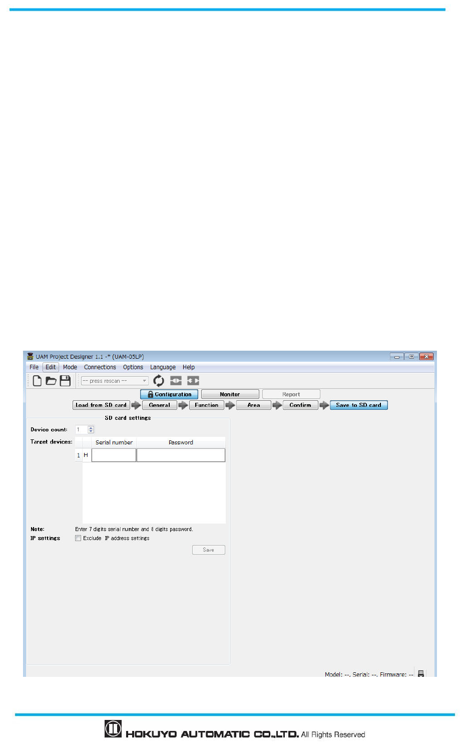
Document No: C-61-00003-3
126
7.22 Save settings to SD card
Configuration data can be saved in the SD card which in turn can be used for directly configuring the
UAM without connecting it to the PC.
<Steps to save>
a) Configure a project in the UAM Project Designer and click confirm button when it is complete.
b) In the confirmation tab, check the general, function and area settings in order.
c) Disconnect UAM if it is connected with the application
d) Click the “Save to SD card” button to switch to the SD card setting tab.
e) In the SD card setting tab (Figure 7-60), enter the 7 digit serial number and the passwords of all the UAMs
intended to be configured with the settings on the SD card. To prevent the change of IP address of the UAM,
check the “Exclude IP address setting” on the tab. This will retain the original IP address of all the UAM.
* It is possible to copy and paste the serial numbers with n-rows and 2 columns from a text file.
f) Verify that SD card is inserted into the PC slot and click “Save” button. Save dialog box as shown in
Figure 7-61 will appear.
g) Select the SD card and click on the “Select Folder” button.
h) Dialog box as shown in Figure 7-62 will appear. Click OK to complete the save.
i) Remove the SD card from its slot.
Figure 7-60 SD Card setting screen
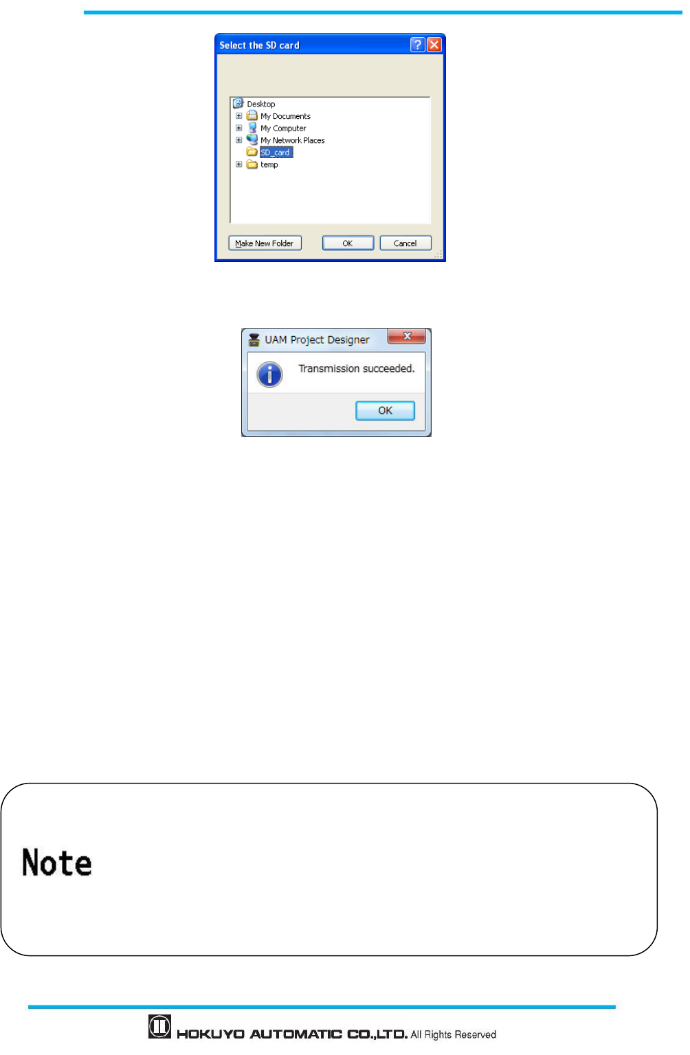
127
Document No: C-61-00003-3
Figure 7-61 SD Card selection screen
Figure 7-62 Transmission complete window
7.23
UAM configuration through SD card
Configuration from the SD card is possible for the devices whose serial number and password are
registered in the SD card. Devices whose serial number or password does not match cannot be configured.
Enter the SD card containing the setting file into the UAM’s SD card slot. Seven segment display will
show the status “F2” to indicate the SD card detection.
If the serial number and password of the device matches with the registered serial number and password
in the file, configuration will start. Seven segment display will show the status “F3”.
At the end of the configuration seven segment display will show the status “F4”. Remove the SD card
from its slot to finish the configuration.
Seven segment display will show the status “F5” briefly and device will restart showing the status “00”.
On successful completion area number will be visible on the display.
Do not switch OFF the UAM or remove the
SD card during the configuration. It
may lead to configuration failure.
Do not connect UAM with the UAM Project Designer by USB cable
during the
configuration from the SD card.
Do not switch off the UAM without removin
g the SD card when the display is
showing the status “F4”. Configuration will be incomplete in such case.
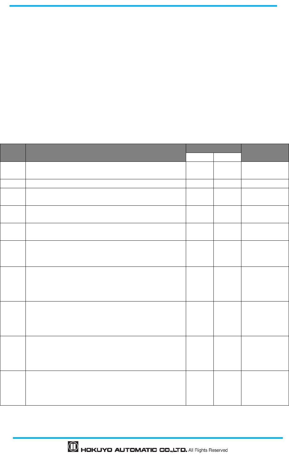
Document No: C-61-00003-3
128
8. Inspection and maintenance
Inspection and maintenance are necessary for safety operation. User must ensure the inspection and
maintenance are carried out as specified in the user’s manual.
Before performing inspection and maintenance, confirm the following items.
The machine or AGV monitored by UAM is switched OFF.
The surrounding of working environment is safe.
8.1 Pre-operation inspection
After configuring the UAM the authorized user should perform pre-operation inspection using a test piece.
It should be performed without connecting the sensor to the system.
Table 8-1 Pre-operation inspection list example
No. Check item Condition Remark
Yes No
1 UAM is correctly mounted at the intended location and
screws are firmly fastened
2 All the wirings are correct
3 The OSSD signal switches from ON state to OFF state
when the test piece is placed inside the protection zone
4 The OSSD signal remains in the OFF state when the test
piece is moved inside the protection zone
5 The OSSD signal switches from OFF state to ON state
when the test piece is removed from the protection zone
6
Area is switched and correctly displayed on UAM when
the input signals are changed according to the area
switching table
7
If UAM is in automatic restart mode, OSSD signal
switches from ON-state to OFF-state when the test piece is
placed inside the protection zone and switches from
OFF-state to ON-state when the test piece is removed
8
If UAM is in manual restart mode, OSSD signal switches
from ON-state to OFF-state when the test piece is placed
inside the protection zone and remains in OFF-state when
the test piece is removed
9
If the start interlock function is configured, starting the
UAM without placing the test piece in protection zone
causes the OSSD signal to remain in OFF-state until the
RESET signal is provided
10
If the muting function is configured, UAM terminates the
muting (OSSD switches to OFF-state) when the test piece
is placed inside the protection zone other than the muting
area even though the muting conditions are fulfilled.
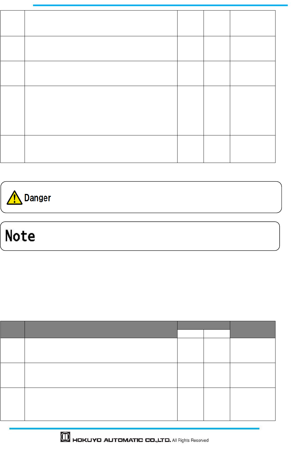
129
Document No: C-61-00003-3
11
If the muting function is configured, UAM does not switch
to mute state when the muting input sequence is different
than the specified sequence.
12
If the muting function is configured, UAM does not switch
to mute state when the time interval between two muting
inputs exceeded the specified time interval
13
If the muting function is configured, the override function
is terminated when the override period exceeds the
specified override period
14
If the reference monitoring function is configured,
displacement of the reference boundary structures or UAM
should cause the OSSD to switch to OFF-state when
displacement exceeds the allowable tolerance. This is
applicable especially if the angle of approach exceeds ±30º
from the detection plane
15
If the area sequence function is configured, OSSD switches
to OFF-state if area switching sequence is different than
the configured sequence.
Note: Stop using the UAM when any check item is marked NO.
8.2 Operation inspection
This test should be performed after completing the pre-operation inspection. It must be performed by taking
the sufficient safety measures. Performing this inspection before pre-operation inspection may damage the
system leading to critical injury or death.
Table 8-2 Operation inspection list example
No. Check item Condition Remark
Yes No
1
The OSSD signal switches from ON-state to OFF-state and
the machine or vehicle stops when the test piece is placed
inside the protection zone
2
The OSSD signal remains in OFF-state and the machine or
vehicle stops when the test piece is moved inside the
protection zone especially at the border
3
If the UAM is in manual restart mode, OSSD signal
switches from ON-state to OFF-state and the machine or
vehicle stops when the test piece is placed inside the
protection zone and remains in OFF-state when the test
Do not modify or dissemble UAM during inspection as this will affect its
detection
capability leading to critical injury or death.
For the traceability, it is recommended to retain
and store the maintenance and
inspection records.
Document No: C-61-00003-3
130
piece is removed
4 If the UAM is in manual restart mode, OSSD remains in
OFF-state when UAM is restarted
5
If the UAM is in automatic restart mode, OSSD signal
switches from ON-state to OFF-state when the test piece is
placed inside the protection zone and switches from
OFF state to ON state when the test piece is removed
6
If the UAM is in automatic restart mode, OSSD remains in
OFF-state when UAM is restarted with obstacle inside the
protection zone
7
If the start interlock function is configured, starting the
UAM without placing the test piece in protection zone
causes the OSSD signal to remain in OFF-state until the
RESET signal is provided
8
If the muting function is configured, UAM terminates the
muting (OSSD switches to OFF-state) when the test piece
is placed inside the protection zone other than the muting
area even though the muting conditions are fulfilled.
9
If the muting function is configured, UAM does not switch
to mute state when the muting input sequence is different
than the specified sequence.
10
If the muting function is configured, UAM does not switch
to mute state when the time interval between two muting
inputs exceeds the specified time interval
11
If the muting function is configured, the override function
is terminated when the override period exceeds the
specified override period
12
If the reference monitoring function is configured,
displacement of the reference boundary structures or UAM
should cause the OSSD to switch to OFF-state when
displacement exceeds the allowable tolerance. This is
applicable especially if the angle of approach exceeds ±30º
from the detection plane
13
If the area sequence function is configured, OSSD switches
to OFF-state if area switching sequence is different than
the configured sequence.
Note: Stop using the UAM when any check item is marked NO.
8.3 Daily inspection
Table 8-3 shows an example of items that should be checked during daily inspection.
Table 8-3 Daily inspection list example
No. Check item Condition Remark
Yes No
1 The OSSD signal switches from ON state to OFF state
when test piece is placed inside the protection zone
2 The OSSD signal remains in OFF state when the test piece

131
Document No: C-61-00003-3
is moved inside the protection zone
3 The OSSD signal switches from OFF state to ON state
when the test piece is removed from the protection zone
4
If the UAM is in automatic restart mode, OSSD signal
switches from ON-state to OFF-state when the test piece is
placed inside the protection zone and switches from
OFF-state to ON-state when the test piece is removed
5
If the UAM is in manual restart mode, OSSD signal
switches from ON-state to OFF-state when the test piece is
placed inside the protection zone and remains in OFF-state
when the test piece is removed
6
If the start interlock function is configured, starting the
UAM without placing the test piece in protection zone
causes the OSSD signal to remain in OFF-state until the
RESET signal is provided
7
If the muting function is configured, UAM terminates the
muting (OSSD switches to OFF-state) when the test piece
is placed inside the protection zone other than the muting
area even though the muting conditions are fulfilled.
8
If the muting function is configured, UAM does not switch
to mute state when the muting input sequence is different
than the specified sequence.
9
If the muting function is configured, UAM does not switch
to mute state when the time interval between two muting
inputs exceeds the specified time interval
10
If the muting function is configured, the override function
is terminated when the override period exceeds the
specified override period
11
If the reference monitoring function is configured,
displacement of the reference boundary structures or UAM
should cause the OSSD to switch to OFF-state when
displacement exceeds the allowable tolerance. This is
applicable especially if the angle of approach exceeds ±30º
from the detection plane
12
If the muting function is configured, UAM terminates the
muting if muting period exceeds the specified maximum
period
13
If the area sequence function is configured, OSSD switches
to OFF-state if area switching sequence is different than
the configured sequence.
8.4 Periodical inspection
Periodical inspection should be performed to ensure the detection capability of UAM. Table 8-4 below
Contamination on the optical window switches the OSSD signal to OFF state.
Document No: C-61-00003-3
132
shows an example of periodical inspection items. It is recommended to perform this inspection at every six
months interval. This inspection should be performed together with the daily inspection.
Table 8-4 Periodical inspection list example
No. Check item Condition Remark
Yes No
1 Screws are tightly fastened
2 No displacement from the original mounting position
3 No scratch or crack on the optical window
4 Screws of the optical window are tightly fastened
5 No oil, grease or dirt on the optical window
6 No visible damage on UAM
7 Cable connector is in good condition and tightly fastened
8
Area is switched and correctly displayed on UAM when
the input signals are changed according to the area
switching table
9 The OSSD signal switches from ON state to OFF state
when the test piece is placed inside the protection zone
10 The OSSD signal remains in OFF state when the test piece
is moved inside the protection zone
11 The OSSD signal switches from OFF state to ON state
when the test piece is removed from the protection zone
12
If the UAM is in automatic restart mode, OSSD signal
switches from ON-state to OFF-state when the test piece is
placed inside the protection zone and switches from
OFF-state to ON-state when the test piece is removed
13
If UAM is in manual restart mode, OSSD signal switches
from ON-state to OFF-state when the test piece is placed
inside the protection zone and remains in OFF-state when
the test piece is removed
14
If the start interlock function is configured, starting the
UAM without placing the test piece in protection zone
causes the OSSD signal to remain in OFF-state until the
RESET signal is provided
15
If the muting function is configured, UAM terminates the
muting (OSSD switches to OFF-state) when the test piece
is placed inside the protection zone other than the muting
area even though the muting conditions are fulfilled.
16
If the muting function is configured, UAM does not switch
to mute state when the muting input sequence is different
than the specified sequence
17
If the muting function is configured, UAM does not switch
to mute state when the time interval between two muting
inputs exceeded the specified time interval
18
If the muting function is configured, the override function
is terminated when the override period exceeds the
specified override period
133
Document No: C-61-00003-3
19
If the muting function is configured, the muting is
terminated when muting period exceeds the specified
maximum muting period
20
If the reference monitoring function is configured,
displacement of the reference boundary structures or UAM
should cause the OSSD to switch to OFF-state when
displacement exceeds the allowable tolerance. This is
applicable especially if the angle of approach exceeds ±30º
from the detection plane
21 Safety relay life span is still valid
22
If the area sequence function is configured, OSSD switches
to OFF-state if area switching sequence is different than
the configured sequence.
8.5 Cleaning the optical window
Dust covering the optical window could affect the UAM’s detection capability If UAM is installed in
dusty environment, regular cleaning of optical window is necessary.
Depending on the level of contamination follow the cleaning method mentioned below.
Wipe the optical window with a clean soft cloth.
Clean the optical window with a soft brush.
Blow off the dust on optical window using an air-blower.
Clean the optical window with mild detergent if it is contaminated with oil or grease particles.
Disconnect the system when cleaning the optical window.
Falling to comply with above could damage the machine leading to
critical injury
or death.
Do not use organic solvents, such as,
thinner, benzene and acetone for cleaning
the UAM. Plastics parts and paint might be affected.
Do not use abrasive cleaner. It might scratch the optical window resulting in t
he
loss of detection capability.
This manual only suggests the basic steps for the inspection and maintenance.
User should perform additional inspection and maintenance if necessary.
User should follow necessary steps in accordance to the working environment.
Perform all the inspections mentioned in this manual when
using the UAM for the first
time.
Contamination on the optical window switches the OSSD signal to OFF state.
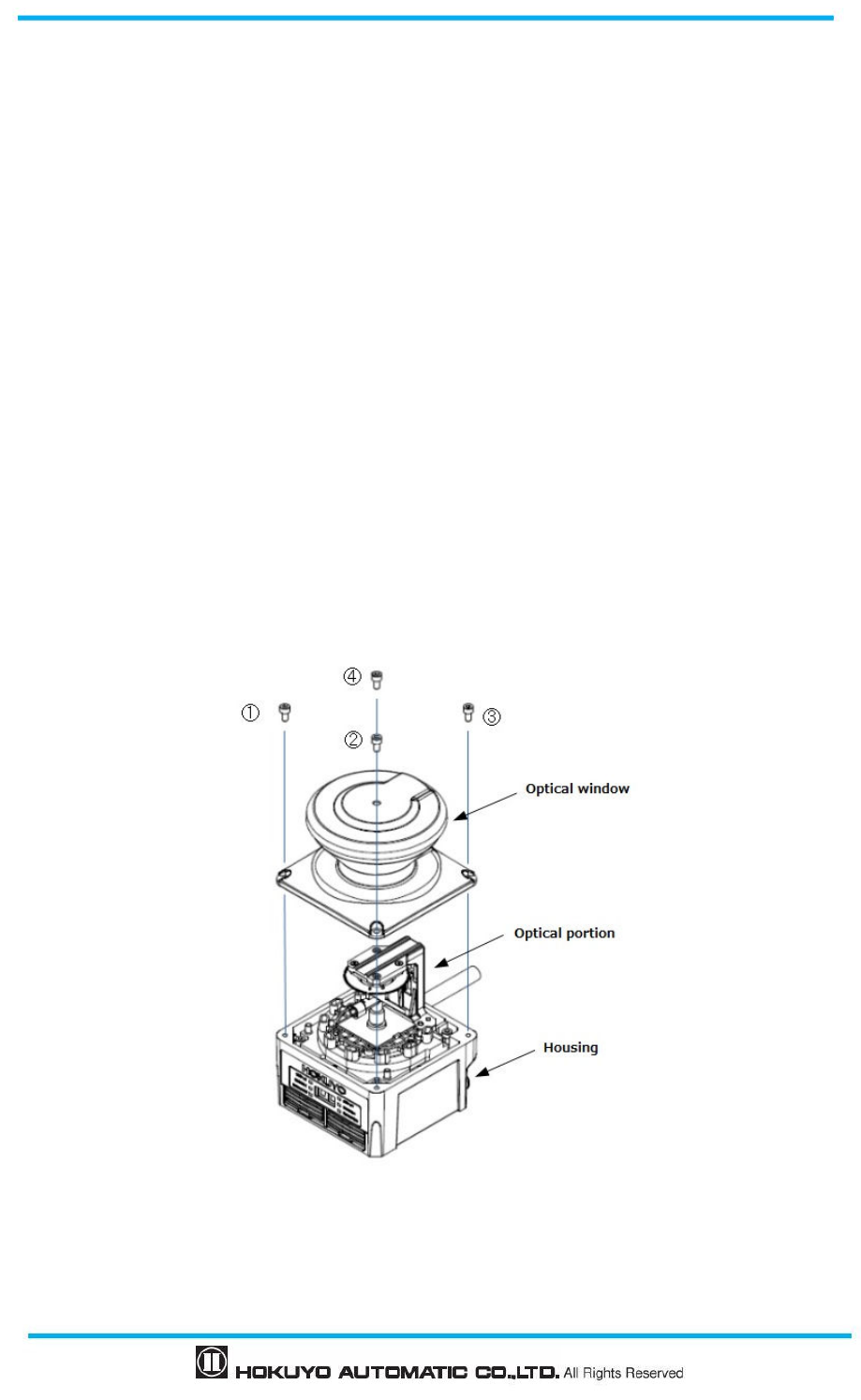
Document No: C-61-00003-3
134
8.6 Replacing the optical window
Replacement of the optical window is needed in the following circumstances:
Crack or scratch on the optical window.
The surface of optical window remains contaminated even after cleaning.
Deterioration of the optical window.
Order the replacement optical window at the nearest distributor or to UAM sales representative.
8.6.1 Method of replacing the optical window
Necessary tools
・Hexagonal wrench
・Torque wrench
Stop using the system and disconnect the UAM. Remove the UAM from its mounting location.
Take the UAM to dust free environment. Remove the dust on UAM if it is present. During the
replacement of optical window, take sufficient measure to prevent the dust from entering inside the
device as this could affect the detection capability of UAM.
Use wrench to remove screws 1 to 4 fixing the optical window.
Figure 8-1 Remove the optical window
To remove the optical window, lift it slowly. Refrain from touching the optical components of UAM.
Avoid applying the force while removing as it could damage the optical component affecting the
135
Document No: C-61-00003-3
detection capability of UAM.
If there is contamination around the case, remove it with a clean cloth without touching the optical part.
If there is contamination on the optical mirror remove it with an air blower.
Set a torque wrench to 0.63Nm.
Do not touch the new optical window with bare hands. It is recommended to wear clean thin gloves to
unpack the new optical window.
Check if seal is attached on the surface of the optical window.
Check the direction to insert the optical window and cover slowly from above. Avoid shaking the
optical components.
Confirm that optical window is correctly attached to the body without any inclination.
Use torque wrench to tight the 4 screws 1 to 4.
Confirm that appearance of the UAM is not abnormal before installing it back to original system.
After installing in the system, adjust the optical window as explained in section 8.6.2.
8.6.2 Adjustment of the optical window
During the operation UAM constantly monitors the transmittance of optical window. When it decreases
due to contamination UAM reports an error. Therefore, it is necessary to measure the initial transmittance of
the new optical window and save it into the device. Contamination should not be present while performing
this adjustment.
<Adjustment steps>
a) Use adjustment software “Optical Window Adjuster” included in the CD. Create a local folder and save
the application into it. Log file generated during the process (format “serial_number_time.log”) and the
adjustment data (format “serial_number_time.csv”) are saved in the same folder where the application is
saved. Retain these files for reference and troubleshooting.
b) Supply the power to UAM and connect with the PC through USB cable.
c) Start Optical Window Adjuster. Window as shown in figure 8-2 will appear.
Optical window is a critical part of UAM therefore it should
not be contaminated or
scratched during the replacement.
Replace the optical window at clean environment to avoid dust particles
from entering
the device affecting the detection capability.
Avoid touching the internal parts of UAM as it may contaminate them decreasing
the
detection capability.
After replacing the optical window it is necessary to apply the
adjustment UAM is
ready to use only after completing the adjustment.
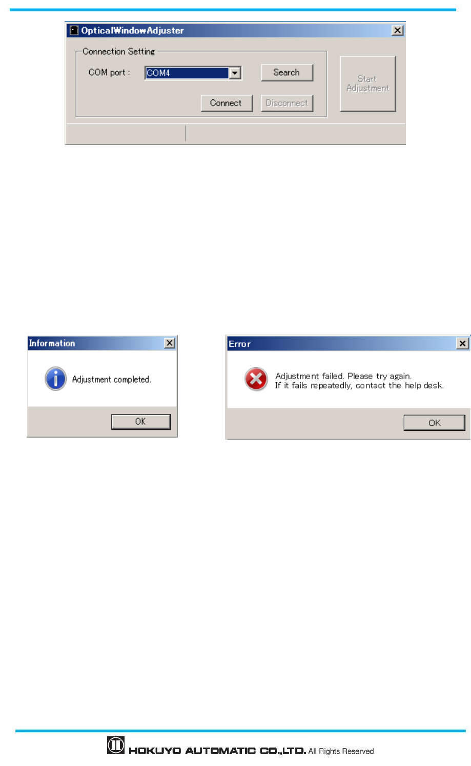
Document No: C-61-00003-3
136
Figure 8-2 Optical Window Adjuster
d) Click connect button after UAM is detected and COM port number is displayed. Click search, if COM
port number is not displayed.
e) Click Start Adjustment button when it is enabled.
f) When application is ready, password window will appear. Enter the password of the device and click
“OK” button. UAM will restart once and start the calibration. It will take approximately 6 minutes to
complete the calibration of 8 contamination channels. 7-segment display on UAM will show the code “CE”
during the process.
Figure 8-3 Adjustment completed display Figure 8-4 Error display
g) When adjustment is complete, dialog box as shown in Figure 8-3 will appear. Click the OK button and
then click disconnect button (Figure 8-2). Remove the USB cable. UAM will switch to normal operation.
Retry the adjustment after checking the optical window and USB connection if an error dialog as shown in
Figure 8-4 is displayed. If adjustment fails even after repeated trial contact the nearest distributor or sales
representative for support. Send the log file and calibration data file for investigating the cause of failure
in such case.
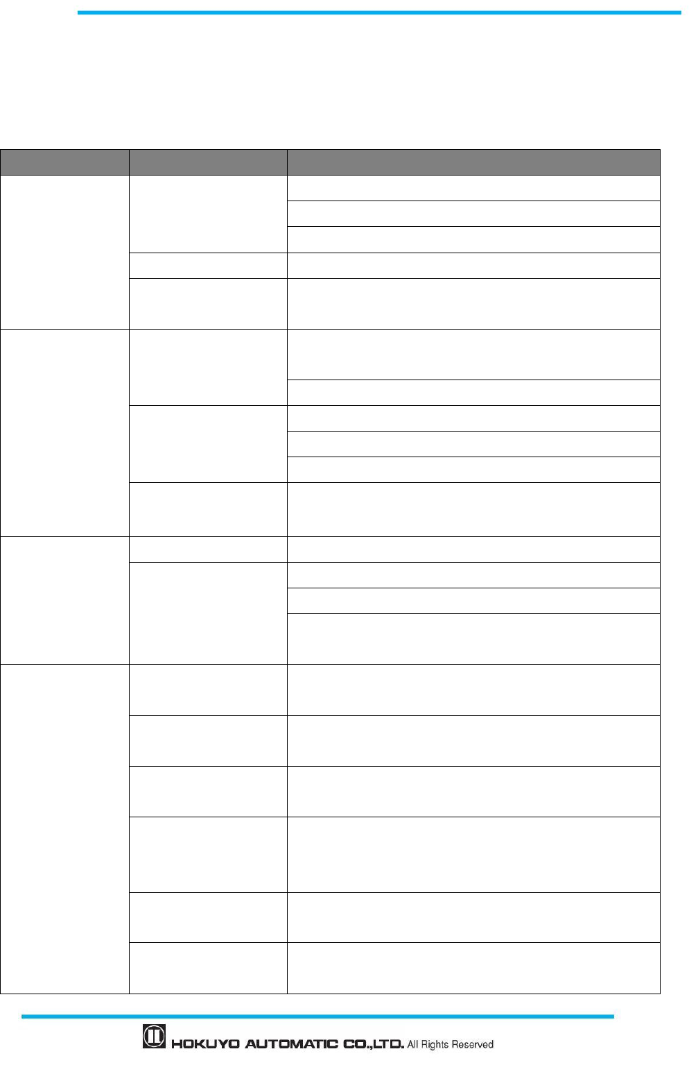
137
Document No: C-61-00003-3
9. Troubleshooting
This chapter describes troubleshooting methods while operating the UAM. Table 9-1 below shows the
troubleshooting list.
Table 9-1 Troubleshooting list
Situation Possible reason Solution suggestion
UAM is not operating
Power supply is
OFF /Over voltage/
Under voltage
Make sure power supply is ON
Check the supplied voltage.
Check the condition of the power supply cable.
Cable is damaged Replace with a new cable
Configuration is
incomplete
Reconfigure UAM
UAM can not
connect with the
UAM Project
Designer
PC trouble
Check the PC’s specification. Make sure the specification is
compatible.
Close the other unrelated applications and reconnect
Power supply is OFF
Make sure the power supply is ON
Check the supplied voltage.
Check the condition of the power supply cable.
USB cable is not
connected to USB port
Make sure the USB is connected to both PC and UAM
Measurement data
is not displayed
Power supply is OFF Make sure the power supply is ON
UAM is in error/lockout
state
Check the supplied voltage.
Check the condition of the power supply cable.
Check the error number in the 7-segment table
Restart UAM if it is blinking
OSSD remains OFF
even though the
protection
zone is free from
obstacle
Light interference Mount UAM at a location free from light interference
Refer to chapter 5.1 for light interference counter measures
Mutual interference Refer to chapter 5.2 for mutual interference counter
measures
Contaminated optical
window
Check for any contamination or damage on the optical
window
Floor is detected
Change the mounting position such that the floor is not
detected.
Reconfigure the detection area.
Background is detected Reconfigure the detection area such that background is not
detected.
Lockout state due to
self-diagnostic function
Check the description of the error number and perform the
possible solution as suggested

Document No: C-61-00003-3
138
UAM is interlocked Check the configuration of the interlock function. If
RES_REQ is ON, supply UAM with RESET signal
Table 9-2 shows the error number of the UAM. These numbers are displayed on the 7-segment display of
UAM. If UAM is unable to resume the normal operation, contact the nearest distributor or sales
representative (included in last page of the manual) for support.
Table 9-2 Error number list
Error number
Details Possible reason Solution suggestion
45 Setting error/Incomplete
setting
Reconfigure UAM Automatic recovery or Input
reset (During Interlock
setting)
56 Invalid area error Confirm the input status during
area switching.
Automatic recovery or Input
reset (During Interlock
setting)
57 Area input connection
error
Confirm the input status during
area switching.
Automatic recovery or Input
reset (During Interlock
setting)
59 Area sequence error Confirm area switching
sequence.
Automatic recovery or Input
reset (During Interlock
setting)
5B Encoder speed error Make sure the encoder speed is
correctly configured
Automatic recovery or Input
reset (During Interlock
setting)
5C Encoder error Confirm the encoder input
status.
Automatic recovery or Input
reset (During Interlock
setting)
5D Encoder speed error Make sure the encoder speed is
correctly configured
Automatic recovery or Input
reset (During Interlock
setting)
5E Invalid area error
(During Encoder is valid)
Confirm the input status during
area switching.
Automatic recovery or Input
reset (During Interlock
setting)
5F Encoder speed error Make sure the encoder speed is
correctly configured
Automatic recovery or Input
reset (During Interlock
setting)
60-63
Motor error
Mount the sensor in a way that
the vibration, bump stated in
the specification does not
exceed.
Automatic recovery or Input
reset (During Interlock
setting)
64 Master-Slave
communication error
Confirm the connection
between master and slave.
Automatic recovery or Input
reset (During Interlock
setting)

139
Document No: C-61-00003-3
70 Optical interference/High
reflective background
Mount UAM at a location free
from light interference. Refer to
chapter 5.1 for light
interference counter measures.
Automatic recovery or Input
reset (During Interlock
setting)
72 Operating temperature
error
Make sure that operating
temperature is within
specification.
Restart the power supply
74-79 Power supply error Make sure that voltage is within
the specification.
Restart the power supply
7C OSSD excess current error
Make sure the OSSD load is
within the specification.
Restart the power supply
7D Slave unit 1 error Check the error code on slave
unit 1
Automatic recovery or Input
reset (During Interlock
setting)
7E Slave unit 2 error Check the error code on slave
unit 2
Automatic recovery or Input
reset (During Interlock
setting)
7F Slave unit 3 error Check the error code on slave
unit 3
Automatic recovery or Input
reset (During Interlock
setting)
80 Master unit error Check the error code on master
unit
Automatic recovery or Input
reset (During Interlock
setting)
84,85
Object in limited detection
zone or contamination on
the optical window.
Clean the optical window (refer
to chapter 8.5 for cleaning the
optical window).
Further, remove any objects
present inside the zone with
limited detection capability
(refer to chapter 5.4) of UAM.
Automatic recovery or Input
reset (During Interlock
setting)
86 Mutual interference error Mount UAM at a location free
from mutual interference.
Refer to chapter 5.2 mutual
interference for counter
measures.
Automatic recovery or Input
reset (During Interlock
setting)
8F SD card detection error Check SD card file or check the
specification of the SD card.
Automatic recovery or Input
reset (During Interlock
setting)
95-9A,
A8, AC
OSSD diagnostic error Check the OSSD connection. Restart the power supply
A6 EDM1 input connection
error
Check the EDM1 connection. Restart the power supply
A7 EDM2 input connection
error
Check the EDM 2 connection. Restart the power supply
A9 Reset input error Check the RESET connection. Restart the power supply
AA Reference monitor error Check for the displacement of
reference structure or UAM
position
Automatic recovery or Input
reset (During Interlock
setting)

Document No: C-61-00003-3
140
B1-C0 Optical window is
contaminated
Refer to chapter 8.5 for
cleaning the optical window
Automatic recovery or Input
reset (During Interlock
setting)
C1 Optical window is
removed or contaminated
Replace or clean the optical
window
Restart the power supply
CE Adjustment of the optical
window is incomplete after
replacement. (Displays CE
during the adjustment of
the optical window.)
Adjust the optical window Automatic recovery or Input
reset (During Interlock
setting)
CF UAM is not configured Configure UAM Automatic recovery or Input
reset (During Interlock
setting)
D3-E6 Configuration is
incomplete
Reconfigure UAM Automatic recovery or Input
reset (During Interlock
setting)
F0 SD card initialization error
Remove the card and try again Automatic recovery or Input
reset (During Interlock
setting)
F1 SD card file content error Check the setting file in the SD
card
Automatic recovery or Input
reset (During Interlock
setting)
Other Error
(41-F5)
Device Error
Make sure that FG wire is
correctly to the ground.
Also check the surrounding
disturbance of the operating
environment.
Mount the sensor within the
stated vibration, bump in the
specification.
Replace UAM if it does not
recover even after restoring the
power supply.
Contact the nearest distributor
or sales representative for the
repair.
Restart the power supply
*
In 7 segment display B and D will display as b and d.
* Error numbers are represented by: 0, 1, 2, 3, 4, 5, 6, 7, 8, 9, A, B, C, D, E, and F.
When adjusting the optical window using “Optical Window Adjuster”, code CE
will be displayed on the 7-segment of UAM. On successful completion of the
adjustment, UAM will resume to normal operation displaying the area number.
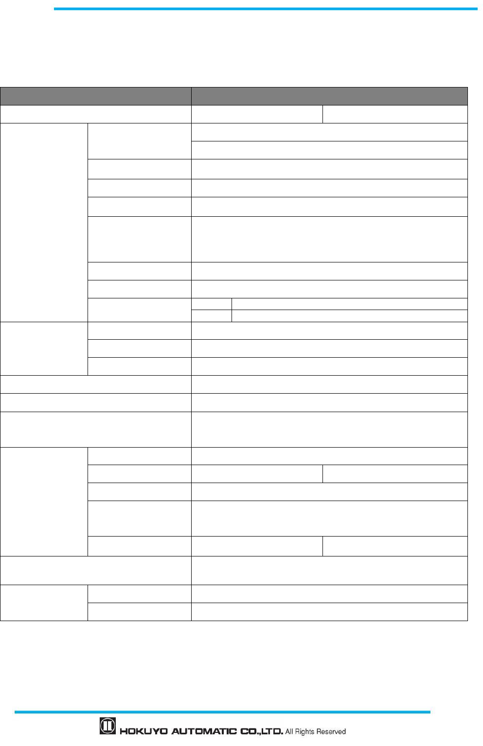
141
Document No: C-61-00003-3
10. Specification
10.1 UAM-05LP
Table 10-1 UAM-05LP specification
Subject
Specifications
Model UAM-05LP-T301 UAM-05LP-T301C
Detection property
Protection Range
Warning Range
Max: 5m
Max: 20m (Non-safety) *1
Distance tolerance*2 +100 mm
Detection capability From Black-Reflector Sheet(1.8%)to Retro-Reflector Sheet
Angular Range 270 º
Minimum Detectable
Width
φ30 mm (Max: 1.8m)
φ40 mm (Max: 2.5m)
φ50 mm (Max: 3.0 m)
φ70 mm/φ 150 mm (Max: 5.0 m)
Scan Frequency 30ms (Rotational Speed: 2000 rpm)
Area pattern Max 32 patterns
Response time
OFF
60 ms~510 ms
ON
270 ms~510 ms
Optics
Element Pulsed Laser Diode
Wave Length 905 nm
Safety Class Laser Class 1
Type Type 3 (IEC61496-1, IEC61496-3)
Functional Safety SIL 2 (Type B, HFT=1) (IEC61508)
PFHd
7.8×10
-8
(T1=20 year): When master slave function is not in use.
1.6×10
-7
(T1=20 year): When master slave function is in use.
Housing
Size 80mm (W)
×
80mm (D)
×
95mm (H) (without cable)
Weight
0.8Kg
0.5Kg
Protection IP65
Case Material Body: Aluminum
Optical Window: Polycarbonate
Connection Cable Flying lead cable length: 3m Waterproof connector: 0.3m
Power supply
DC 24V ±10%: when operation using converter power supply
DC 24V -30%/+20%: when operation using battery
Supply current Normal (without load)
6W
Max. (with load)
50W
*1. Distance when reflectance of the object is 90% or above.
*2. Additional distance of 200mm is needed when the UAM is working under high reflective background.
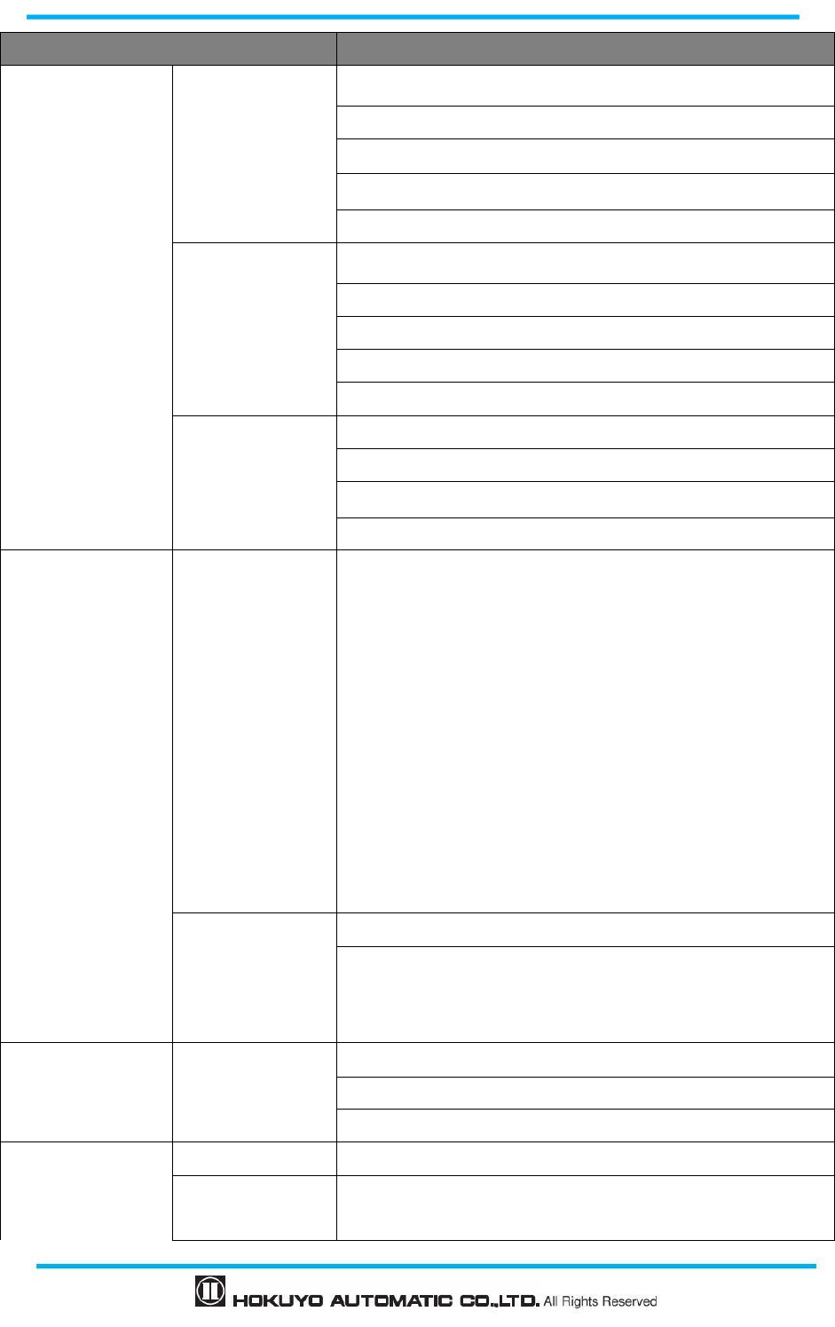
Document No: C-61-00003-3
142
Subject Specifications
Output
OSSD 1/2 (Safety)
Output type (High side SW)
Output current:(Max:500mA) *3
Leak current (Max:1mA)
AWG 26
Load tolerance (L/R=25ms, C=1µF)
OSSD3/4 (Safety)/
WARNING 1/ 2
(Non-Safety)
Output type (High side SW)
Output current:(Max:250mA) *3
Leak current (Max:1mA)
AWG 28
Load tolerance (L/R=25ms, C=1µF)
RES_REQ 1,
RES_REQ 2,
MUT_OUT 1,
MUT _OUT 2
Output types (PNP Transistor)
Output current (Max: 200mA)
Leak current (Max: 1mA)
AWG 28
Input
Area pattern 32
(5 Inputs x 2 Channels)
EDM1,
EDM2,
MUTING1,
MUTING2,
MUTING3,
MUTING4,
OVERRIDE1,
OVERRIDE2,
RESET1,
RESET2
Input Impedance 4.7 kΩ
AWG 28
ENC_A1,
ENC_A2,
ENC_B1,
ENC_B2
Input Impedance 4.7 kΩ
AWG 28
Interface Configuration USB2.0 (USB micro type-B connector)
RS-485
Ethernet 100BASE-TX (Water proof connector)
Environmental
resistance
Temperature -10ºC to +50ºC (No freezing)
Storage
Temperature
-25ºC to +70ºC (No freezing)

143
Document No: C-61-00003-3
Humidity 95% RH with no condensation
Storage Humidity 95% RH with no condensation
Surrounding
Intensity*4
Less than 1500 lx
Vibration
Frequency range: 10~55 Hz Sweep rate: 1 octave/min
Amplitude: 0.35 mm ±0.05 mm
Bump Acceleration: 98m/s 2 (10G) Pulse duration: 16 ms
Outdoor Operation
Not permitted
Altitude Below 2000m
*3. Total current supply of OSSD output and Warning output should be below 1.0A.
*4. When the light sources are located at ≥5º from the detection plane of UAM.
Document No: C-61-00003-3
144
11. Package contents
The following items are included in the package.
a)
UAM ×1
b) Quick Reference ×1
c)
Configuration CD ×1
145
Document No: C-61-00003-3
12. Options
12.1 Base mounting bracket (Model: UAM-BK03)
This base bracket can be used to change the horizontal alignment of the UAM during installation. This
bracket is useful especially in preventing the mutual interference when two or more UAMs are used. (Refer
to external dimension)
12.2 Rear mounting bracket (Model: UAM-BK04)
This rear bracket can be used to change the vertical and horizontal alignment of the UAM during
installation. This bracket is useful especially in preventing the mutual interference when two or more UAMs
are used. (Refer to external dimension)
12.3 USB cable (Model: UAM-MUSB)
This cable is used to connect the UAM and PC. Length of the USB cable is 1m.This cable is used during
the configuration of the UAM.
12.4 Ethernet cable (Model: UAM-ENET)
This cable is used for connecting the UAM and PC for the measurement data output. Cable Length is 3m.
12.5 Configuration CD (Model: UAM-CD03)
This CD contains the configuration software, UAM Project Designer, USB driver and other related
documents.
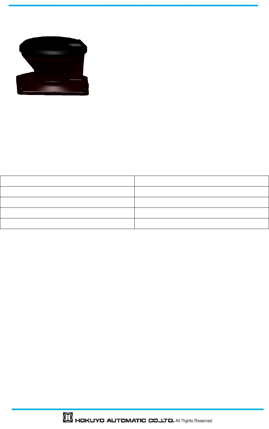
Document No: C-61-00003-3
146
12.6 Optical window for replacement (Model: UAM-W002)
Replacement part when optical window is scratched or damaged.
12.7 Cover Bracket (Type: UAM-BK05)
Cover brackets for optical window protection that can be used in combination with mounting brackets. (See
the dimension)
12.8 Connector Cable (UAM-05LP-T301C Only)
Model Cable Length (m)
UAM-5C02C 2
UAM-5C05C 5
UAM-5C10C 10
UAM-5C20C 20
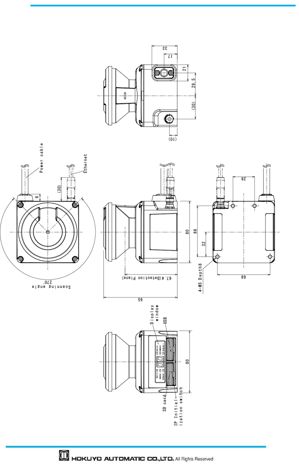
147
Document No: C-61-00003-3
13. External dimension
13.1 UAM-05LP
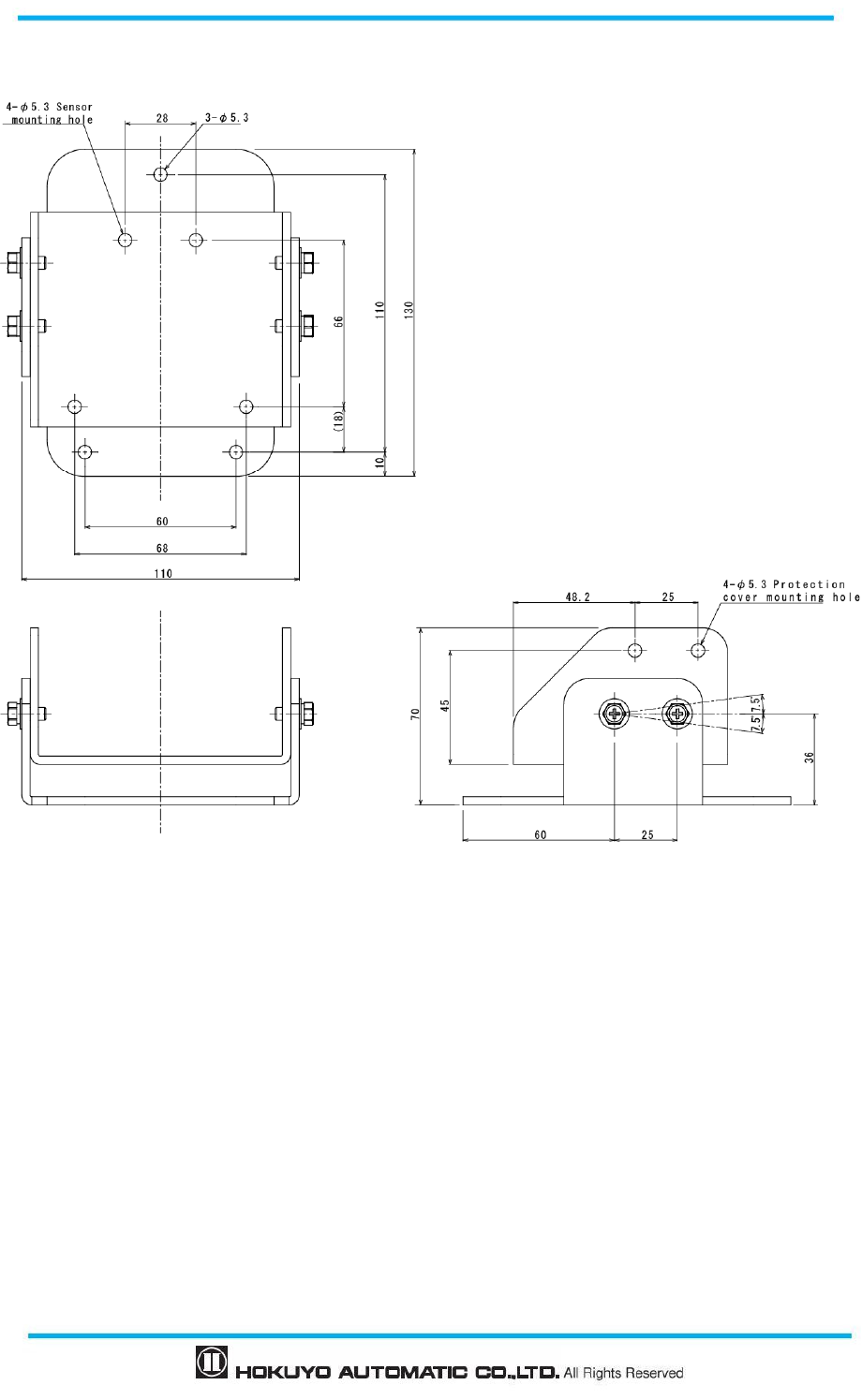
Document No: C-61-00003-3
148
13.2 Base mounting bracket
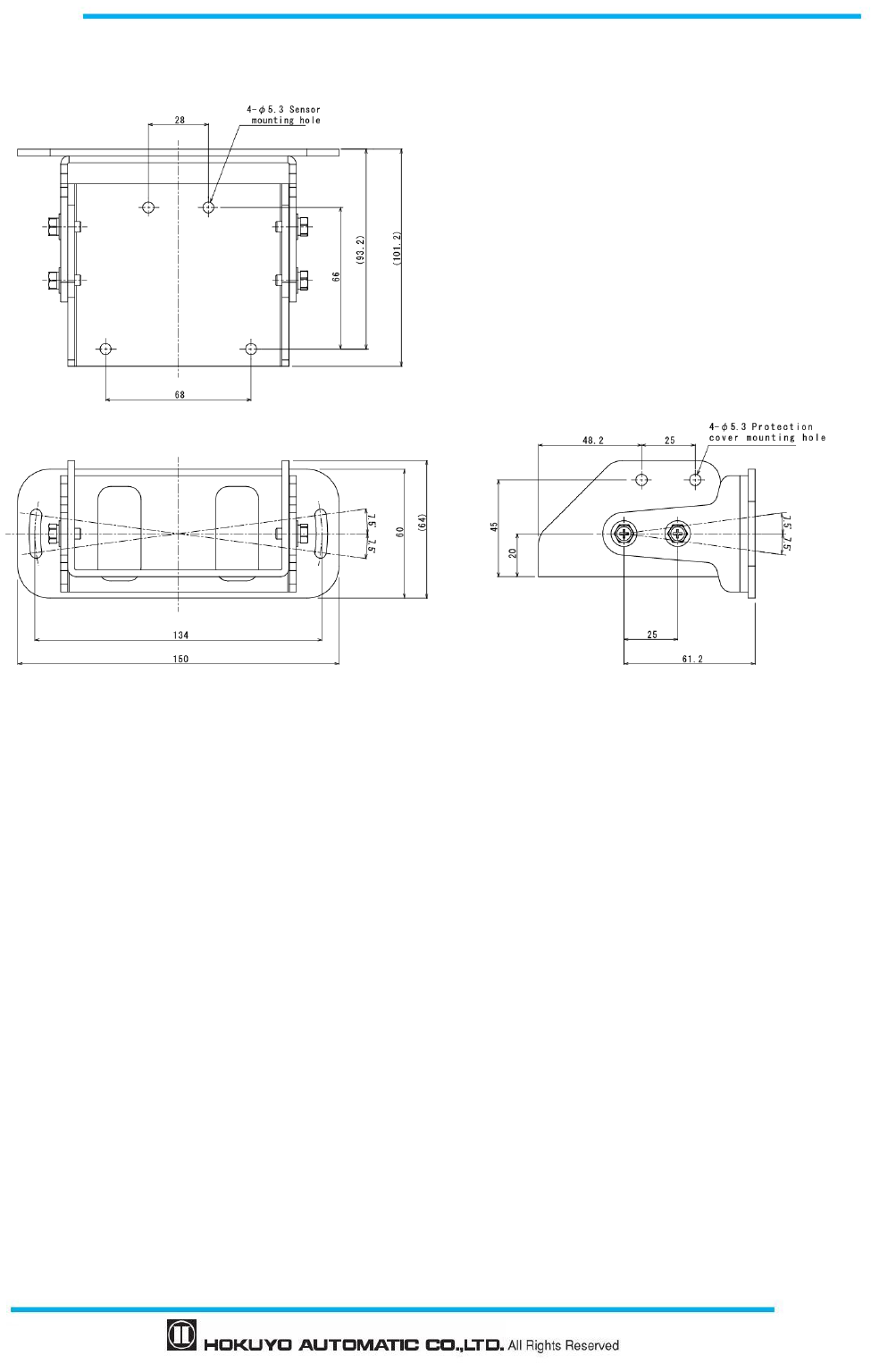
149
Document No: C-61-00003-3
13.3 Rear mounting bracket
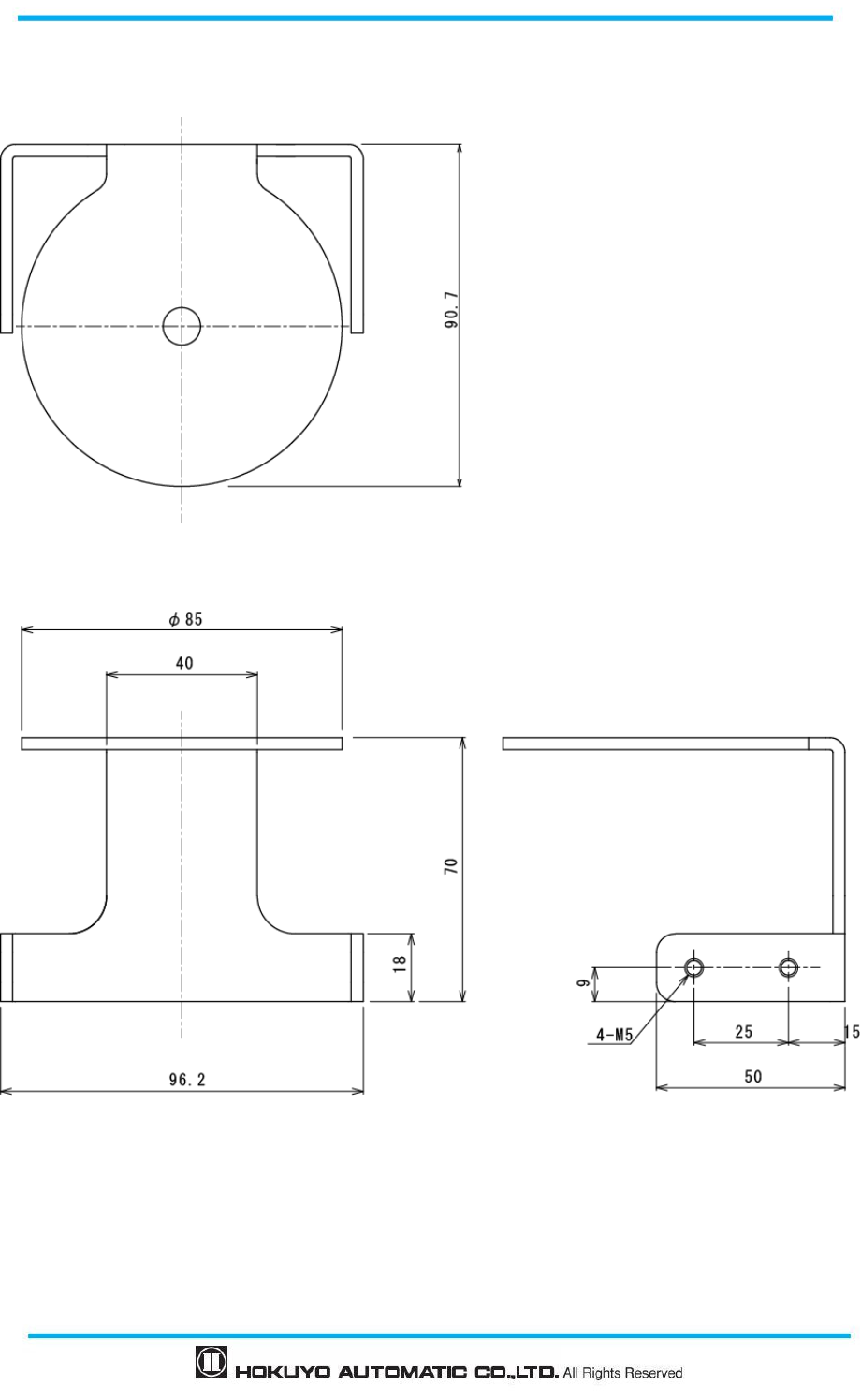
Document No: C-61-00003-3
150
13.4 Cover Protection Bracket
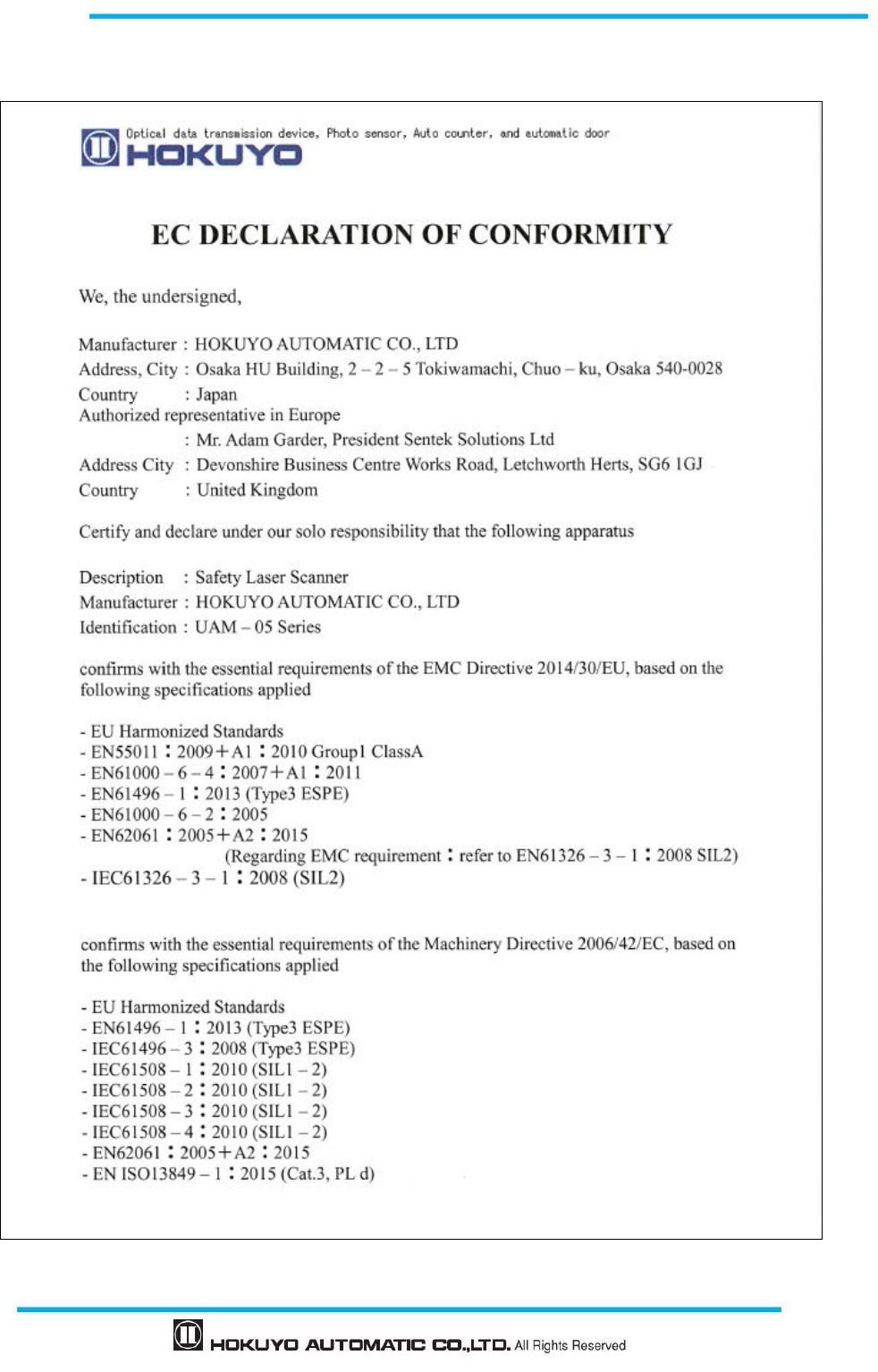
151
Document No: C-61-00003-3
14. EC Declaration of conformity
Document No: C-61-00003-3
152
153
Document No: C-61-00003-3
15. Revision history
Amended No. Revision date Details
- September 2015 First Release
1 November 2015 UL directives and standards added, Error correction
2 January 2017 Standards updated, Connector model added
Following sections added and/or modified
- Default configuration values added
- 7-segment upside down display function added
- Laser off mode added
- Scan skip function added
- Minimum detection width of 150mm added
- Encoder tolerance modified
- Area and measurement data inverting and rotating function
added
- Compatibility with Windows 10
- Other minor corrections
3 December 2017 - Minimum detection width of 40mm added
- Optical window contamination warning function added
- Response time of reference monitoring function added
- Import and export function for area information added
- Method to generate polygonal shape for the area added
- Method to generated area using the teaching function is
modified.
- Method to specify region for the teaching function is added.
- Other minor corrections

Document No: C-61-00003-3
154
16. Representative contacts
Asia and others
Hokuyo Automatic Co., Ltd.
540-0028 Osaka HU building, 2-2-5 Tokiwamachi, Chuo-ku, Osaka, Japan
Tel: +81-6-6947-6333
Fax: +81-6-6947-6350
E-mail: overseas-sales@hokuyo-aut.co.jp
URL: http://www.hokuyo-aut.jp
Europe
Hokuyo Automatic Co., Ltd.
Amsterdam Branch
Prof. J. H. Bavincklaan 2, 1183 AT Amstelveen, The Netherlands
Tel: +31 20 240 01 10
E-mail: amsterdam.branch@hokuyo-aut.co.jp
URL: http://www.hokuyo-aut.jp
North America
Hokuyo Automatic USA Corporation
2019 Van Buren Ave, Suite A, Indian Trail, NC 28079, U.S.A.
Tel:+1-704-882-3844 Fax:+1-704-628-0582
E-mail:sales@hokuyo-usa.com
URL :http://www.hokuyo.com
★ The contents described in this document are based on the information as of December 2017. The
external dimensions, specifications etc. are subject to change without notice.
overseas-sales@hokuyo-aut.co.jpently
used
