Dometic 289023121 HiPromatic ZigBee module User Manual Copyright Develco A S
Dometic GmbH HiPromatic ZigBee module Copyright Develco A S
Dometic >
User Manual

Copyright © Develco A/S
All rights reserved.
Develco assumes no responsibility for any errors, which may appear in this document. Furthermore,
Develco reserves the right to alter the hardware, software, and/or specifications detailed herein at
any time without notice, and Develco does not make any commitment to update the information
contained herein.
All the trademarks listed herein are owned by their respective owners.
RoHS

Data Sheet for DevCom 06 ZigBee Module v1.00
2
Contents:
1 Overview ............................................................................................ 5
1.1 Specifications ................................................................................... 5
1.2 General Features ............................................................................... 5
1.3 Interfaces ........................................................................................ 5
1.4 Software Configurations ..................................................................... 6
1.5 ZigBee Technology ............................................................................ 6
2 Electrical Specifications ........................................................................ 7
2.1 Operating Conditions ......................................................................... 7
2.2 DC Electrical Characteristics ............................................................... 7
2.3 AC Electrical Characteristics ................................................................ 8
3 Pin Assignments and Definitions ............................................................ 9
3.1 Assignments for Debug Interface ...................................................... 10
4 Mechanical Specifications ................................................................... 11
4.1 Mechanical Dimensions .................................................................... 11
4.2 Mechanical Implementation .............................................................. 11
5 Certifications .................................................................................... 13
6 Antenna Characteristics ..................................................................... 14
6.1 Internal F-antenna .......................................................................... 14
7 Assembly Guidelines .......................................................................... 15
7.1 PCB Layout Guidelines ..................................................................... 15
7.2 Soldering Guidelines ........................................................................ 19
8 Ordering Information ......................................................................... 21
9 Contact Information .......................................................................... 22
10 About Develco A/S ............................................................................ 23

Data Sheet for DevCom 06 ZigBee Module v1.00
3
Acronyms
The following list shows the acronyms used in this document.
A/D Analog to Digital
CE Conformité Européenne
EMC Electromagnetic Compatibility
GPIO General Purpose Input Output
I2C Inter Integrated Circuit
IC Integrated Circuit
IDE Integrated Development Environment
JTAG Joint Test Action Group
LNA Low Noise Amplifier
MAC Medium Access Control
MCU Micro Controller Unit
PA Power Amplifier
PCB Printed Circuit Board
PHY Physical Layer
SBW Spy-Bi-Wire
SCI Serial Communication Interface
SMD Surface Mount Device
SPI Serial Port Interface
SW Software
UART Universal Asynchronous Receive Transmit
USB Universal Serial Bus

Data Sheet for DevCom 06 ZigBee Module v1.00
4
References
For more detailed information, please consult the following documents:
Texas Instruments, Inc.
“MSP430 Hardware Tools, Users Guide SLAU208E, Rev. April 2010”
“MSP430F543xA, Datasheet SLAS612A, Rev. March 2010”
“CC2529, Datasheet SWRS068, Rev. December 2007”
“CC2590, Datasheet SWRS080, Rev. September 2008”

Data Sheet for DevCom 06 ZigBee Module v1.00
5
1 Overview
The DevCom 06 ZigBee Module offers a fast-track approach to development of IEEE 802.15.4 and
ZigBee applications. The module comes with a 24-pole connector with access to different I/Os.
The module has an internal antenna. The DevCom 06 ZigBee Module is available as a module with
standard software, but the module is also available with customized software developed by Develco
A/S in close co-operation with the customer.
The module is based on TI’s 16-bit MSP430 series and the 2.4 GHz ZigBee compliant radio, CC2520.
The DevCom 06 ZigBee Module includes the RF front end module, CC2590/CC2591 for extended
range performance.
The board is supplied with software based on Texas Instruments Z-Stack, ZigBee-2007 Release.
1.1 Specifications
• Dimensions: 24 x 25mm
• Storage temperature: -30 to +105°C
• Operating temperature: -10 to +70°C
• Transmitter output power (maximum): 14 dBm1
• Receiver sensitivity: -101 dBm @ 1% PER
• Supply voltage range: 2.4 to 3.6V @ 25MHz system frequency
• Bit rate: 250 kbps
• Data rate: 200 kbps
• Frequency band: 2400 to 2483.5 MHz
• Number of channels: 16
• Current consumption, Rx: 32.1 mA
• Current consumption, Tx: 54.3 mA @ 12 dBm
• Flash memory: 256 kB
• RAM: 16 kB
1.2 General Features
• 2.4 GHz IEEE 802.15.4
• Low power consumption (down to 1.5 µA in standby mode. For cable replacement application
down to 100 µA)
• VCC I/O level
• Up to 18 GPIOs (UART, Keyboard inputs, A/D, PWM, Comparator, I2C and SPI)
• On-board antenna and prepared for external antenna
• CE compliant2
• RoHS compliant according to the EU Directive 2002/95/EC
• Software development board available
1.3 Interfaces
• 24 pin DIL connector (2mm spacing)
o Up to 18 GPIOs
Up to 4 UARTs
Up to 7 Interrupt inputs
Up to 6 A/D inputs
Up to 6 Timer / Compare outputs
1 Output power shall be limited to comply with European regulations
2 Pending

Data Sheet for DevCom 06 ZigBee Module v1.00
6
Up to 2 I2Cs
Up to 3 SPI
o VCC
o GND
1.4 Software Configurations
Modules are preloaded with MAC based cable replacement software.
1.5 ZigBee Technology
The IEEE 802.15.4 specification is a cost-effective, low data rate (<250 kbps), 2.4 GHz and 868/915
MHz wireless technology designed for personal-area peer-to-peer and star networks. The IEEE
802.15.4 standard is the basis of an application and network layer protocol called ZigBee.
A number of companies, including Develco A/S, have formed a consortium known as the ZigBee
Alliance. The purpose of this consortium is to create a specification for mesh networking and
application profiles. The companies also perform interoperability and certification testing.
For additional information about the ZigBee Alliance, please visit the following website
http://www.ZigBee.org

Data Sheet for DevCom 06 ZigBee Module v1.00
7
2 Electrical Specifications
This section details the operating conditions, DC characteristics and AC characteristics of the DevCom
06 ZigBee Module.
2.1 Operating Conditions
Table 2.1 Operating Conditions
Parameter
Min
Typ
Max
Unit
Conditions
Supply Voltage (VCC)
2.4
3.0
3.6
V
Frequency Range 2.405 2.480 GHz 16 available channels in the 2.4
GHz ISM band
Storage Temperature Range -30 +105 °C 0% to 90% relative humidity
(non-condensation)
Operating Temperature Range -10 +70 °C 0% to 90% relative humidity
(non-condensation)
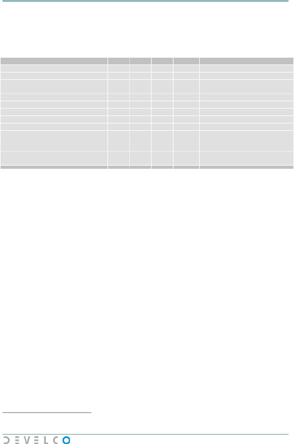
2.2 DC Electrical Characteristics
Table 2.2 DC Electrical Characteristics3
Parameter
Min
Typ
Max
Unit
Conditions
Current Consumption4 , Standby 8
μA
VCC = 3.0V
(Hibernate and Stop3 mode)
Excluding on-board regulation
Current Consumption, Transmit
Mode (Nominal) 65
mA VCC = 3.0V
(Transmit mode and Run
mode)
Output power limited for CE
compliance
Current Consumption, Receive Mode 30
mA
VCC = 3.0V (Receive mode and
Run Mode)
Input High Voltage (V
ih
)
0.70*
VCC
V
All digital inputs (-10°C to
+70°C)
Input Low Voltage (V
il
)
0.25*
VCC
V
All digital inputs (-10°C to
+70°C)
Output High Voltage (V
oh
)
V
CC
-
0.6
V
All digital inputs (-10°C to
+70°C) @ 6mA
Output Low Voltage (Vol) 0.6 V All digital inputs (-10°C to
+70°C) @ 6mA
3 VCC=3.0V, Ta=+25°C, unless otherwise noted
4 Current consumptions are for DevCom 06-x and include PHY and MAC only
Data Sheet for DevCom 06 ZigBee Module v1.00
8
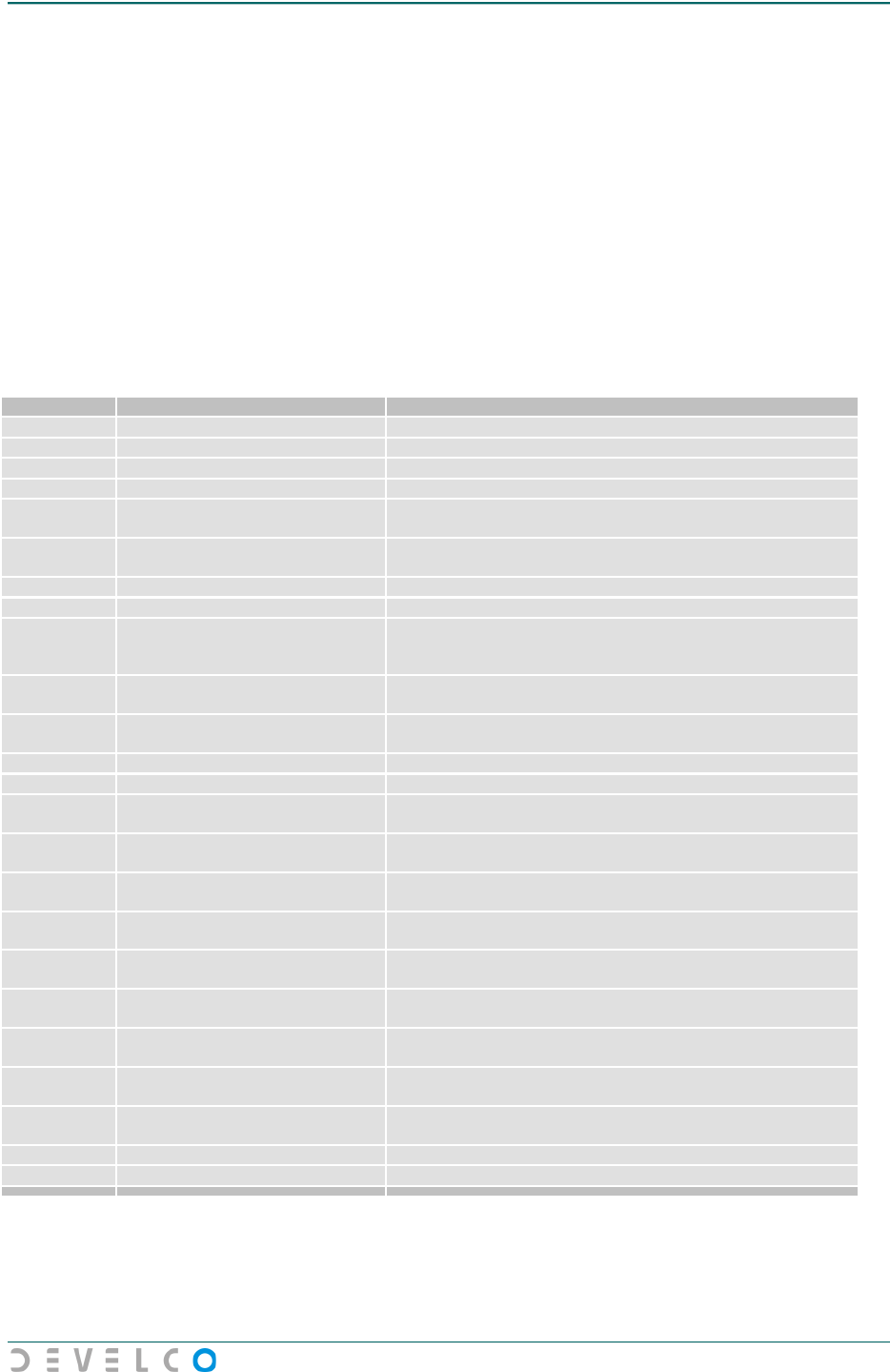
2.3 AC Electrical Characteristics
Table 2.3 AC Electrical Characteristics5
Parameter
Min
Typ
Max
Unit
Conditions
RF Data Rate
250
kbps
Over the air data rate
Receiver Sensitivity TBD
dBm ≤1% Packet Error Rate, 20-
byte payload
Saturation (Maximum Input Level)
TBD
dBm
Frequency Error Tolerance
200
kHz
Symbol Rate Error Tolerance
80
ppm
Transmitter Output Power
(Maximum) TBD
dBm Output power shall be limited
to comply with European
regulations
Transmitter Output Power
(Nominal)
TBD
dBm Output power limited for CE
compliance
6
5 VCC=3.0V, Ta=+25°C, unless otherwise noted
6 Excluding antenna gain
Data Sheet for DevCom 06 ZigBee Module v1.00
9
3 Pin Assignments and Definitions
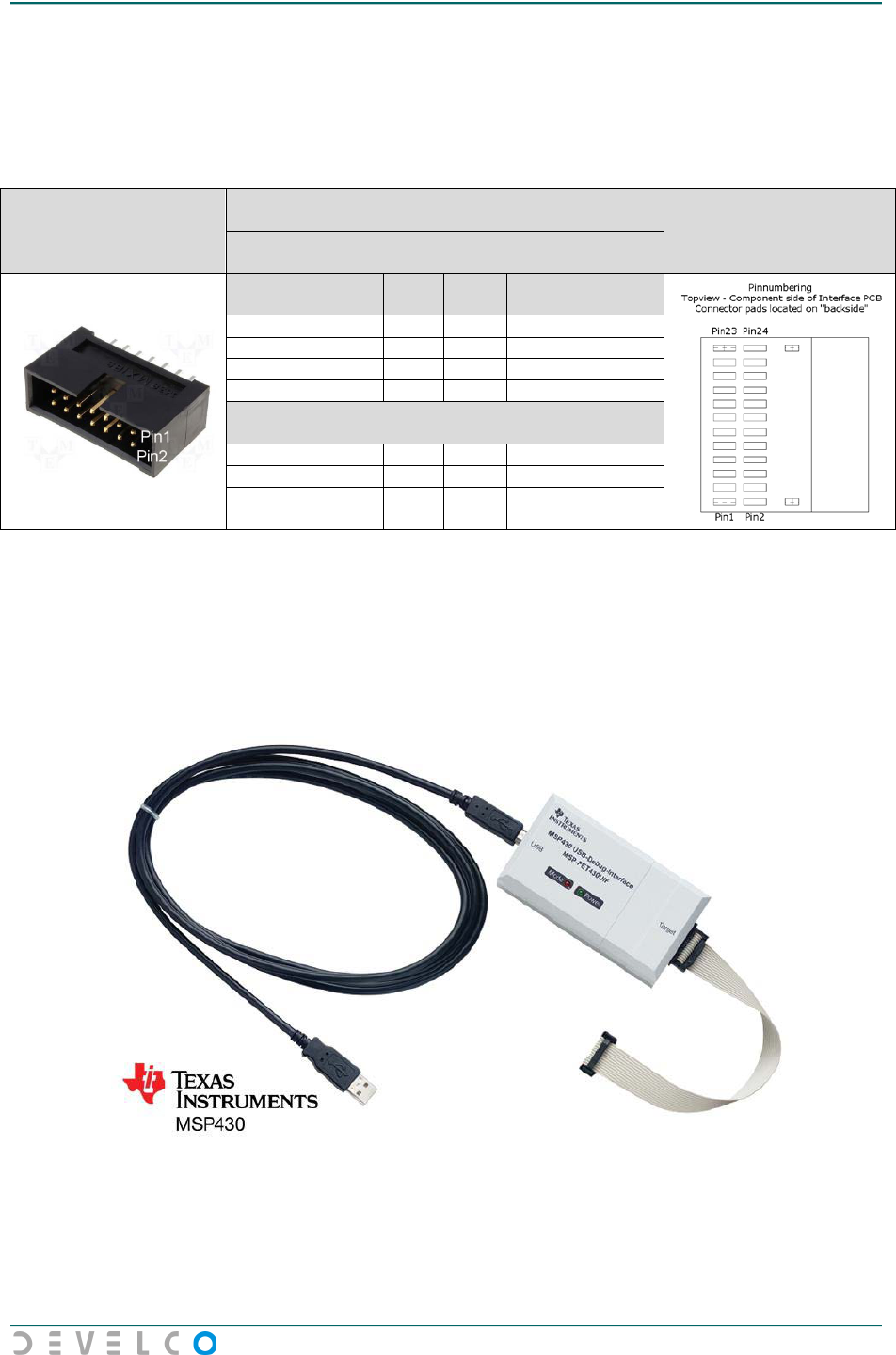
The interface of the DevCom 06 ZigBee Module consists of 24 connections. These connections are
located in 2 rows of 12 pins each with a pitch of 2mm.
18 of these connections are available as digital General Purpose Input-Output connections for SW
development purposes, which includes In-circuit debug and flash programming, UART, Keyboard
inputs, A/D, Timer, Comparator, I2C and SPI.
Table 3.1 details the pin-out of the 24 interface connections of the DevCom 06 ZigBee Module .
For more detailed information about GPIO functionalities, please see the “MSP430F5438 Data Sheet”
from Texas Instruments.
Table 3.1 Pin Definitions
Pin Number
Pin Name
MSP430 Connections and/or Description
1
VCC (Supply Voltage)
Internally connected to AVCC, DVCC1, DVCC2, DVCC3 and DVCC4
2
Reset
Connected to /RST
3
BKGD
Connected to TEST/SBWTCK
4
GND
Internally connected to AVSS, DVSS1, DVSS2, DVSS3 and DVSS4
5
UART0-RxD / IRQ2
P5.7/UCA1RXD/UCA1SOMI +
P2.3/TA1.2
6 UART0-TxD / IRQ3 P5.6/UCA1TXD/UCA1SIMO +
P2.5
7
UART1-RxD / SPI1(MISO)
P10.5/UCA3RXD/UCA3SOMI
8
UART1-TxD / SPI1(MOSI)
P10.4/UCA3TXD/UCA3SIMO
9 PWM4 / I2C1 (SDA) P1.0/TA0CLK/ACLK +
P2.4/RTCCLK +
P10.1/UCB3SIMO/UCB3SDA
10 PWM1 / I2C1 (SCL) P2.6/ACLK +
P10.2/UCB3SOMI/UCB3SCL
11
SPI0 (SCLK) / UART4-RxD
P3.5/UCA0RXD/UCA0SOMI +
P9.0/UCB2STE/UCA2CLK
12
SPI0 (MOSI) / UART2-TxD
P9.4/UCA2TXD/UCA2SIMO
13 SPI0 (MISO) / UART2-RxD P9.5/UCA2RXD/UCA2SOMI
14
SPI0 (CS) / UART4-TxD
P3.4/UCA0TXD/UCA0SIMO +
P9.3/UCB2CLK/UCA2STE
15 ADC5 / SPI1 (SCLK) P6.5/A5 +
P10.0/UCB3STE/UCA3CLK
16 IRQ4 / SPI1 (CS) P2.2/TA1.1 +
P10.3/UCB3CLK/UCA3STE
17 IRQ0 / PWM3 P2.7/ADC12CLK/DMAE0 +
P4.0/TB0.0
18 IRQ1 / ADC4 P6.4/A4 +
P2.1/TA1.0
19
PWM0 / ADC0
P6.0/A0 +
P4.1/TB0.1
20 PWM2 / ADC1 P6.1/A1 +
P4.2/TB0.2
21
I2C0 (SDA) / ADC2
P6.2/A2 +
P9.1/UCB2SIMO/UCB2SDA
22 I2C0 (SCL) / ADC3 P6.3/A3 +
P9.2/UCB2SOMI/UCB2SCL
23
GND
Internally connected to AVSS, DVSS1, DVSS2, DVSS3 and DVSS4
24
GND
Internally connected to AVSS, DVSS1, DVSS2, DVSS3 and DVSS4
Data Sheet for DevCom 06 ZigBee Module v1.00
10
3.1 Assignments for Debug Interface
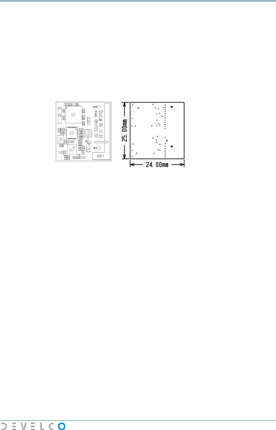
The DevCom 06 ZigBee Module has all connections necessary for easy programming and debugging
of the module. The USB Flash Emulation Tool, MSP-FET430UIF from Texas Instruments can be used
for these purposes. The following connection scheme shows the necessary interconnections, between
the programmer and the DevCom06 module.
MSP-FET430UIF
Connector
2 wire JTAG interconnection
(SpyByWire)
Devcom06
Connector
Vcc supplied from Target:
Vcc
MSP-FET430UIF
Description
Pin
Pin
Devcom06
Description
TDO/TDI
1
2
RESET
Vcc Target
4
1
Vcc
TCK
7
3
BKGD/Test
Gnd
9
4
Gnd
Vcc supplied from Programmer:
Vcc
TDO/TDI
1
2
RESET
Vcc Tool
2
1
Vcc
TCK
7
3
BKGD/Test
Gnd
9
4
Gnd
For proper utilization and detailed information of the USB Flash Emulation Tool, please look into the
“MSP430 Hardware Tools – User’s Guide” from Texas Instruments. The User’s guide can be
downloaded from http://www.ti.com
Figure 3.1 - MSP430-FT430UIF
Data Sheet for DevCom 06 ZigBee Module v1.00
11
4 Mechanical Specifications
This chapter details the mechanical specifications for the DevCom 06 ZigBee Module. Parameters
described in detail are mechanical dimensions and mechanical implementation.
4.1 Mechanical Dimensions
The DevCom 06 ZigBee Module is available for SMD assembling only. The mechanical dimensions is
shown in Figure 4.2. Maximum height including PCB is 2.9mm.
Figure 4.2 Mechanical dimensions
4.2 Mechanical Implementation
To achieve the specified performance and comply with regulatory approvals, the DevCom 06 ZigBee
Module must meet the following requirements when implemented to an interface platform.
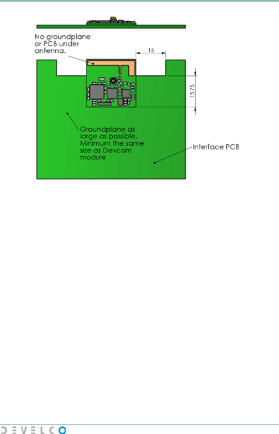
There must not be any ground plane or power plane above or below the antenna part of the module.
FR-4 material under the antenna is, however, acceptable. The minimum distance from the DevCom
06 ZigBee Module to one of the mentioned planes must be at least 15mm to each side. See Figure
4.3 for implementation guidelines. All dimensions are designated in millimetres.
It is recommended that the ground plane of the interface platform is a as large as possible; the
minimum ground plane acceptable must cover the DevCom 06 ZigBee Module , except for the
antenna area as mentioned above.
It is important that the two pads for ground connections to the external interface board are fixed
properly, to provide optimal ground connection and mechanical stability.
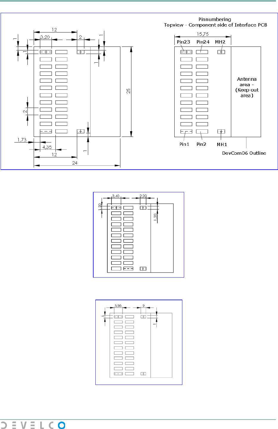
The drawing below is seen from top side (component side) and shows the soldering connections for
the module.
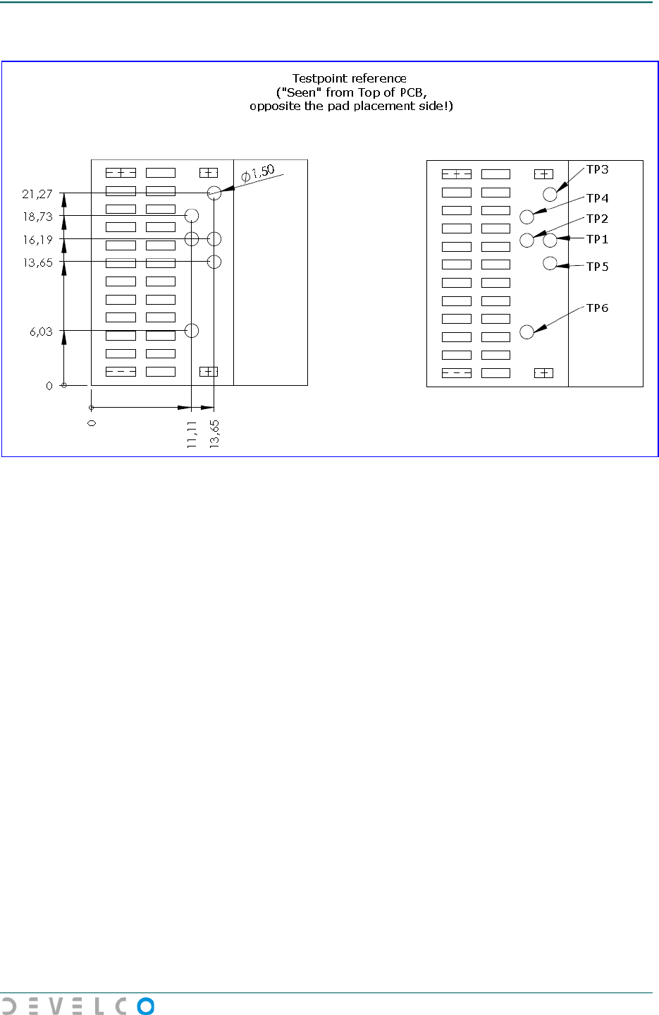
It is required that the test points on the solder side of the DevCom 06 ZigBee Module are isolated
from the ground plane. Se chapter 7 for coordinates.
Data Sheet for DevCom 06 ZigBee Module v1.00
12
Figure 4.3 Requirements for mechanical implementation of DevCom 06 ZigBee
Module
The ground plane on the interface board can be on both sides or on one side only.

Data Sheet for DevCom 06 ZigBee Module v1.00
13
5 Certifications
The DevCom 06 ZigBee Module is fully CE certified7
and compliant to the following standards:
• EN 300 328 V1.7.1 (2006-05) EMC for Radio spectrum Matters (ERM); Data transmission
equipment for operating in the 2.4GHz ISM band and using wide band modulation techniques.
• EN 301 489-1 V1.6.1 (2005-09) EMC for Radio spectrum Matters (ERM); Common technical
requirements.
• EN 301 489-17 V1.2.1 (2002-08) EMC for Radio spectrum Matters (ERM); Specific conditions
for 2.4GHz wideband transmission systems.
• EN 60950 (2000-June) Safety of information technology equipment
• EN 50371 (2002) Basic restrictions related to human exposure
Part 15 - Class B digital device or peripheral §15.105(b)
“This equipment has been tested and found to comply with the limits for a Class B digital
device, pursuant to part 15 of the FCC Rules. These limits are designed to provide
reasonable protection against harmful interference in a residential installation. This
equipment generates, uses and can radiate radio frequency energy and, if not installed and
used in accordance with the instructions, may cause harmful interference to radio
communications. However, there is no guarantee that interference will not occur in a
particular installation. If this equipment does cause harmful interference to radio or
television reception, which can be determined by turning the equipment off and on, the user
is encouraged to try to correct the interference by one or more of the following measures:
—Reorient or relocate the receiving antenna. —Increase the separation between the
equipment and receiver. —Connect the equipment into an outlet on a circuit different from
that to which the receiver is connected. —Consult the dealer or an experienced radio/TV
technician for help.”
This device complies part 15 of FCC rules and RSS-210 of IC rules. Operation is subjected to the
following two conditions : (1) this device may not cause interference, and (2) this device must accept any
interference, including interference that may cause undesired operation of the device. The term "IC"
before the equipment certification number only signifies that the Industry Canada technical
specifications were met.
Changes or modification not expressly approved by the partly responsible for compliance could void the
user’s authority to operate the equipment.
Ce dispositif est conforme à la norme partie 15 de FCC et CNR-210 d'Industrie Canada. Le terme «IC»
devant le numéro de certification de l'équipement signifie uniquement que les spécifications techniques
d'Industrie Canada ont été respectées.
Les changements ou modifications non expressément approuvés par la partie responsable de conformité
pourrait annuler l'autorité de l'utilisateur à utiliser l'équipement"
FCC ID: 2AC5K289023121
IC: 12307A-289023121
M/N::"DevCom 06 ZigBee Module
7 Pending
Data Sheet for DevCom 06 ZigBee Module v1.00
14
6 Antenna Characteristics
This section details the antenna part of the DevCom 06 ZigBee Module. The module has an internal
antenna implemented.
NOTE:
If any other antenna than the default F-antenna is used, the DevCom 06 ZigBee Module is no longer
certain to comply with the already approved certifications. To ensure full compliance, approval is
therefore necessary.
6.1 Internal F-antenna
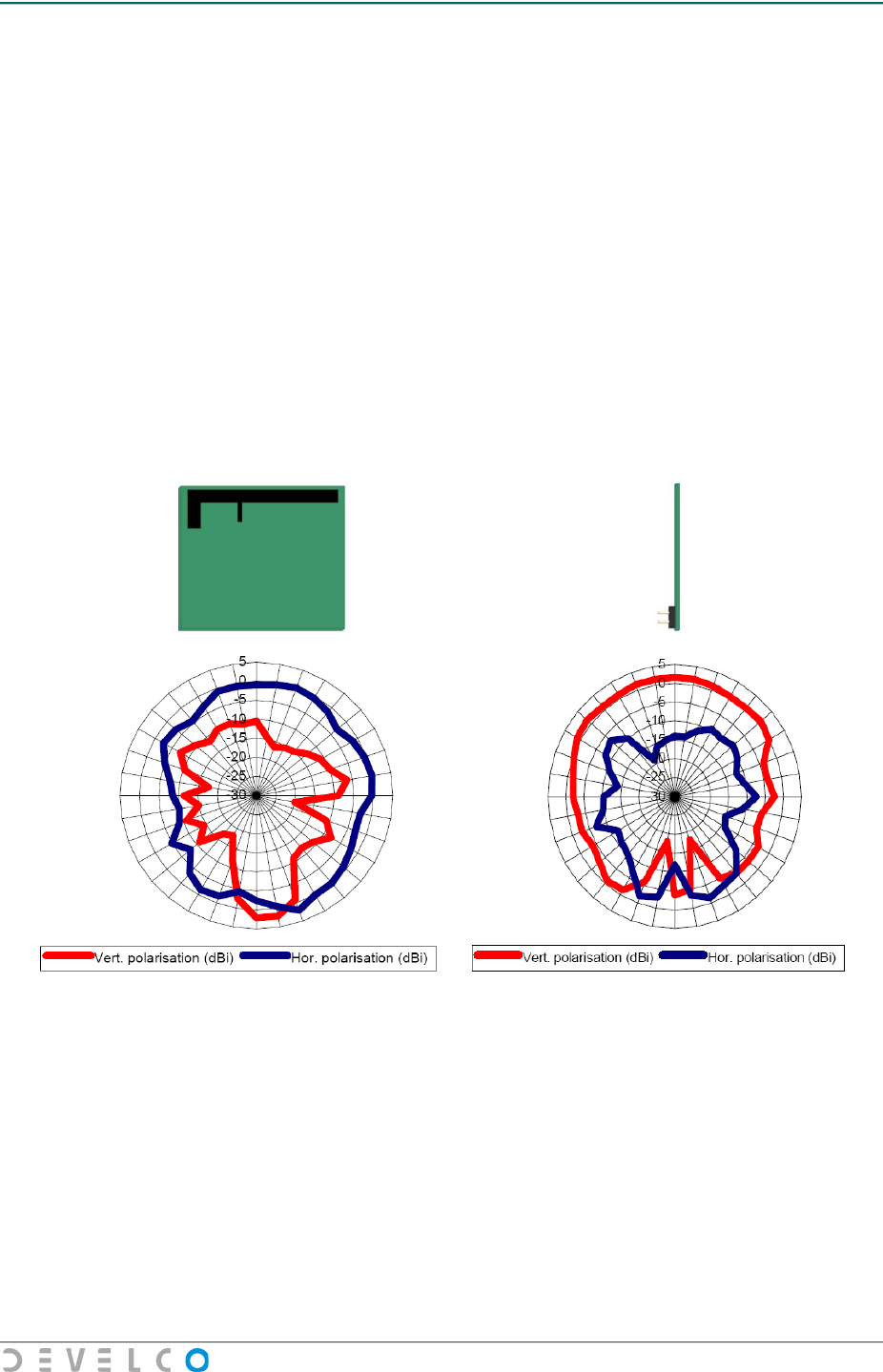
The antenna implemented on the DevCom 06 ZigBee Module is an in-PCB F-antenna. The F-antenna
has good efficiency and an almost omni-directional radiation pattern.
Figure 6.1 and Figure 6.2 show the DevCom 06 ZigBee Module horizontal and vertical radiation
patterns. The red colour represents the vertical polarization and the blue colour the horizontal
polarization. Both radiations are measured in dBi.
Figure 6.1 Horizontal radiation pattern Figure 6.2 Vertical radiation pattern

Data Sheet for DevCom 06 ZigBee Module v1.00
15
7 Assembly Guidelines
This chapter details the assembly guidelines for the DevCom 06 ZigBee Module, including guidelines
for PCB layout and soldering.
7.1 PCB Layout Guidelines
This section describes the guidelines for recommended footprint for the interface PCB for SMD
assembling of the DevCom 06 ZigBee Module. The guidelines include recommendations on copper
layer, solder mask and solder paste.
These recommendations are guidelines only and may need to be adjusted, depending on other
components on the interface PCB and the assembly facility in general.
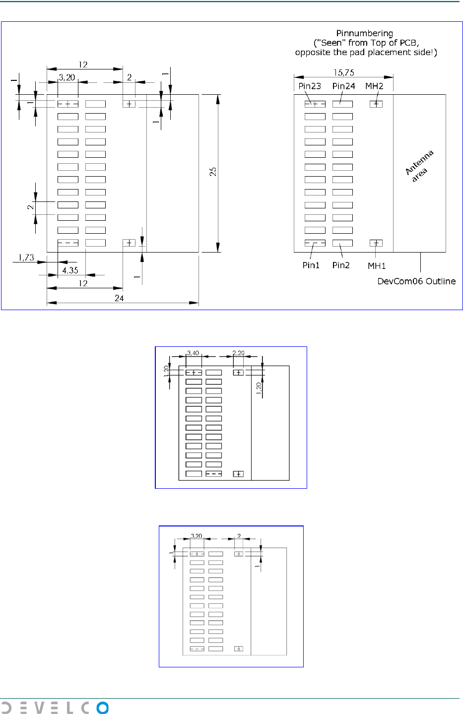
The data for copper layout, solder mask and solder paste for the DevCom 06 ZigBee Module are
illustrated in Figure 7.4, Figure 7.5 and Figure 7.6. A similar footprint is recommended for the
interface PCB as well and illustrated in Figure 7.1, Figure 7.2 and Figure 7.3. It is recommended to
adjust the stencil opening and thickness in correlation with the interface PCB.
Test points are illustrated in Figure 7.7. Sufficient clearances for the test points are highly
recommended to implement in the ground layer on the interface PCB.
All dimensions are in millimetres with a tolerance of approximately ±0.05mm.
Data Sheet for DevCom 06 ZigBee Module v1.00
16
Figure 7.1 - Recommended copper layout for the Interface Module
Figure 7.2 Recommended solder mask for the Interface Module
Figure 7.3 Recommended solder paste for the Interface Module
Data Sheet for DevCom 06 ZigBee Module v1.00
17
Figure 7.4 Copper layout for the DevCom 06 ZigBee Module
Figure 7.5 Solder mask for the DevCom 06 ZigBee Module
Figure 7.6 Solder paste for the DevCom 06 ZigBee Module
Data Sheet for DevCom 06 ZigBee Module v1.00
18
Figure 7.7 Test points for the DevCom 06 ZigBee Module
Data Sheet for DevCom 06 ZigBee Module v1.00
19
7.2 Soldering Guidelines
This section describes soldering guidelines for the interface PCB for SMD assembling of the DevCom
06 ZigBee Module. The guidelines include recommendations on the soldering profile.
Concerning humidity and sensitivity, the DevCom 06 ZigBee Module must be handled in accordance
with IPC/JEDEC J-STD-020C classification 3.
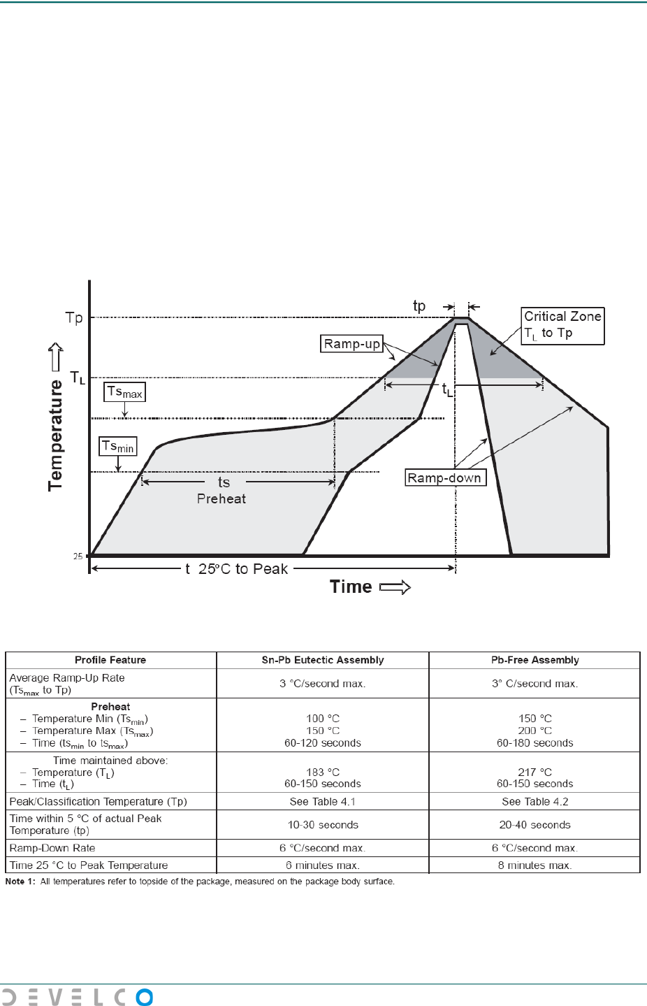
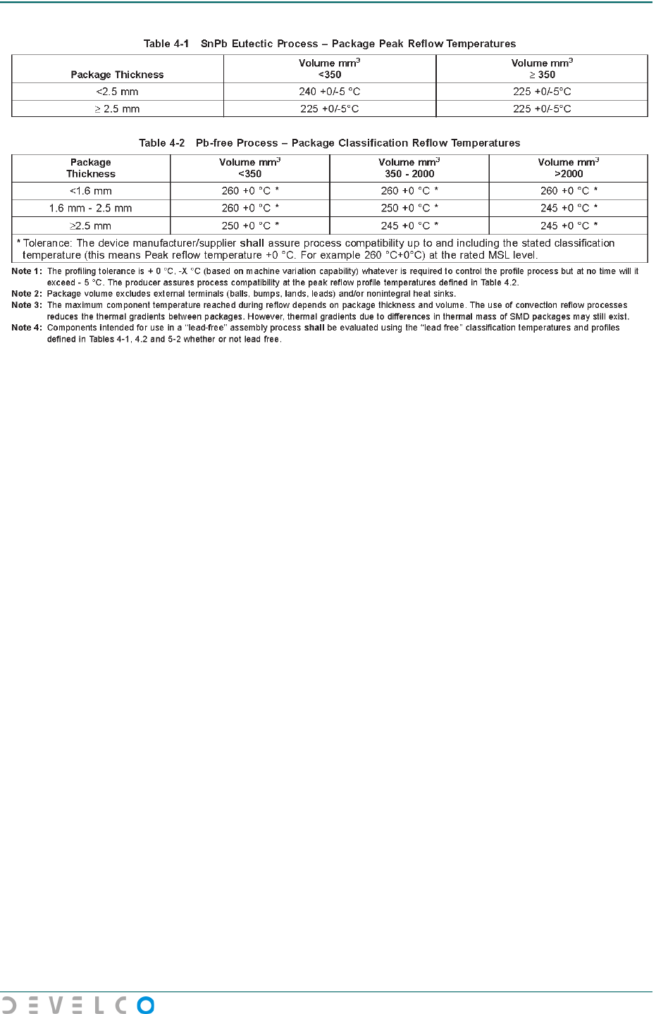
Figure 7.8 illustrates a recommended reflow soldering profile for the DevCom 06 ZigBee Module
(Extracted from IPC/JEDEC J-STD-020C). These recommendations are guidelines only and may need
to be adjusted, depending on other components on the interface PCB and the assembly facility in
general.
Figure 7.8 Soldering guidelines for the DevCom 06 ZigBee Module
Data Sheet for DevCom 06 ZigBee Module v1.00
20

Data Sheet for DevCom 06 ZigBee Module v1.00
21
8 Ordering Information
The DevCom 06 ZigBee Modules includes the following variants:
Product name
Order number
Develco item number
DevCom 06-SB ZigBee Module
DevCom06-SB
A0043Z0000

Data Sheet for DevCom 06 ZigBee Module v1.00
23
10 About Develco A/S
Develco is an independent design house. It was founded in 1989, and most of our staff have an
engineering background.
Develco's core competencies are in electronic engineering and embedded software. As we work in
close partnerships in an extensive and highly competent network, we are able to handle very
comprehensive projects. Our customers are primarily industrial operators who have their own product
line. We provide complete solutions that turn our customers into leaders in their field.
Develco transfers knowledge across business lines. We work in several lines of business - Wireless,
Automotive & Industrial. The synergy achieved by working with diverse companies in a broad
spectrum of businesses benefits all of our customers.
Technological development is an area of high priority in Develco. We continuously strive to introduce
new technologies and improve quality, doing our utmost to keep our customers on the leading edge.
Develco is a member of the ZigBee Alliance and is also a Freescale Alliance Partner. We have been
developing ZigBee enabled products since January 2004, e.g. for home control, security and AMR
systems, the first of which have already been brought into production.
Develco is ISO14001:2004 and ISO9001:2000 certified.
