Druck ADTSTOUCH-01 ADTS Touch User Manual K0553 tle
Druck Ltd ADTS Touch K0553 tle
UserManual.wiki
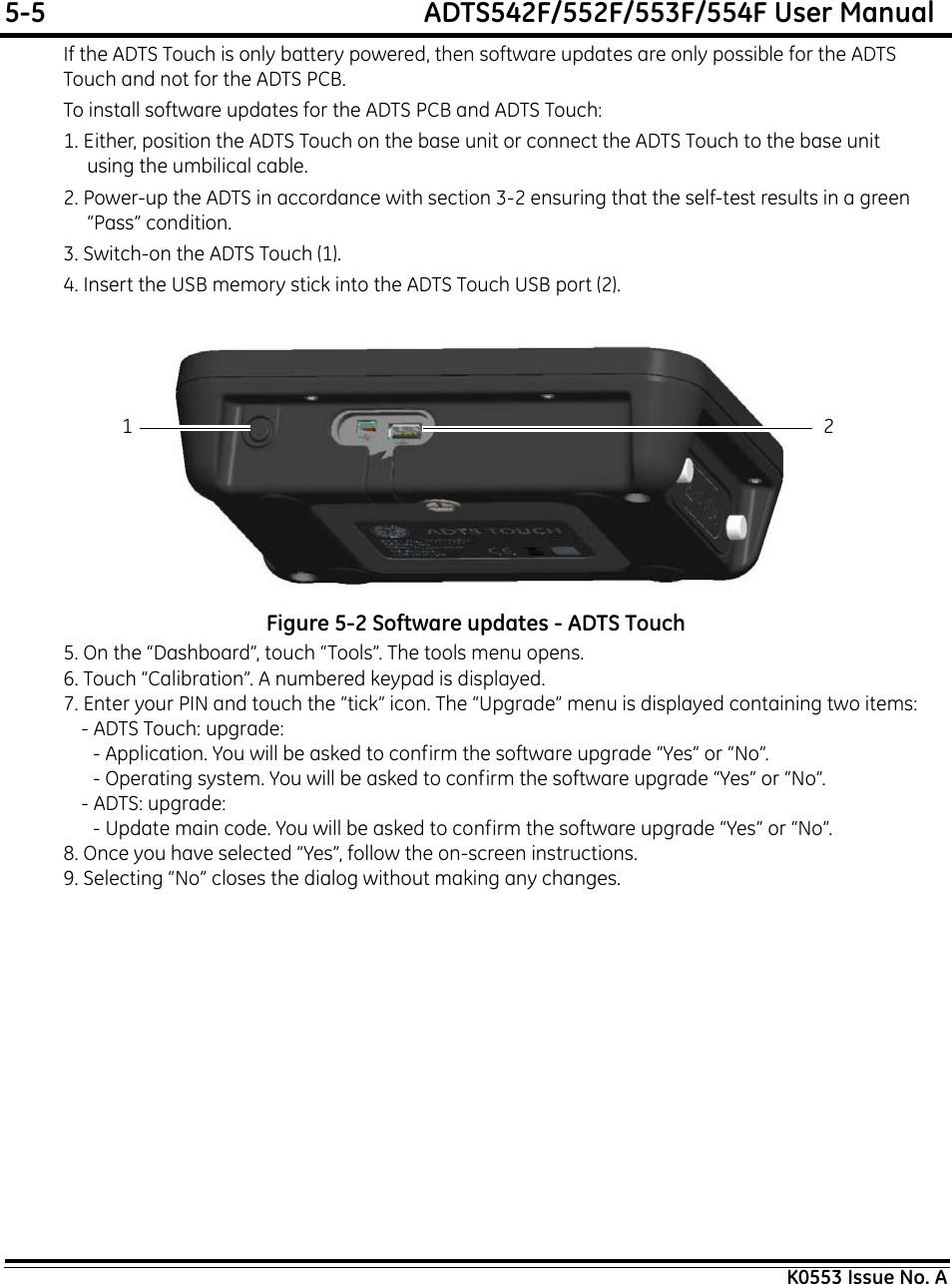
>
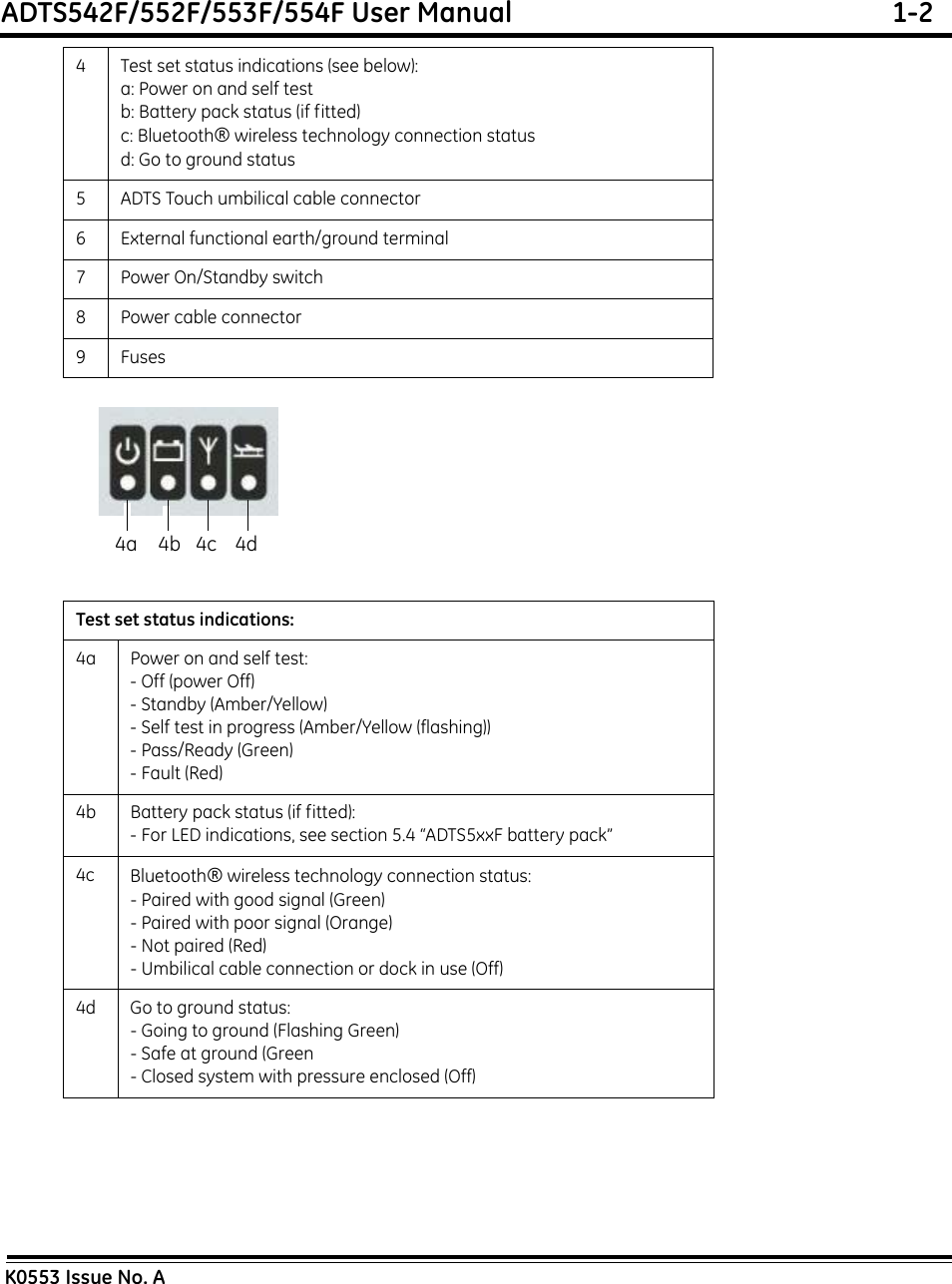
Druck
>
ADTSTOUCH-01 User Manual
>
Users Manual
Contents
1.
Users Manual
2.
User Manual Bluetooth
Users Manual
Navigation menu
Upload a User Manual
Namespaces
Wiki Guide
HTML
PDF
Info
Views
User Manual
Discussion / Help
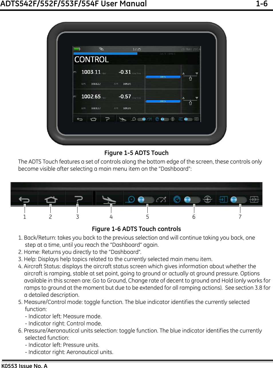
Navigation

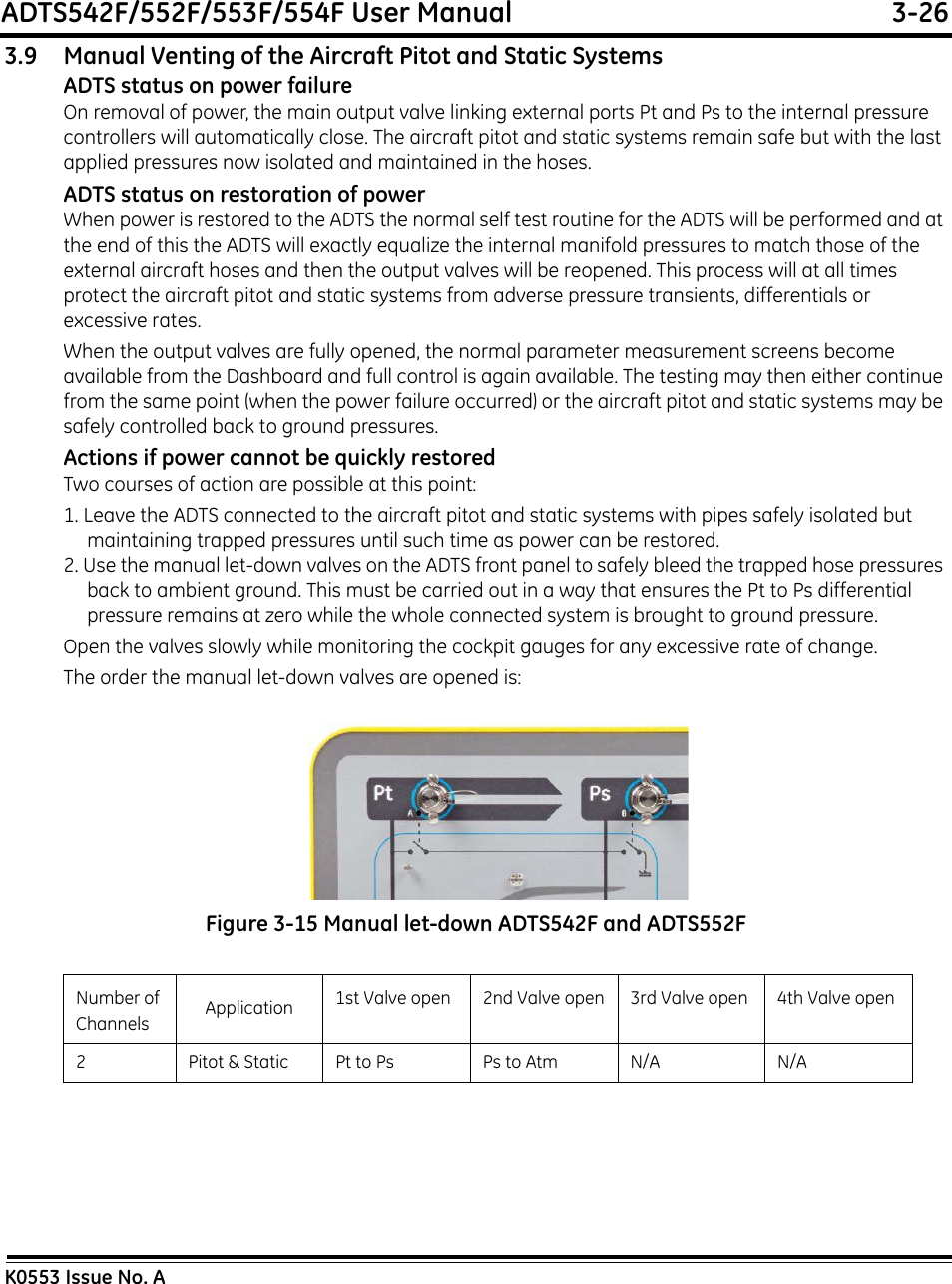
![ADTS542F/552F/553F/554F User Manual 2-2K0553 Issue No. A• To return the ADTS for calibration or repair complete the return goods procedure as detailed in 2.3.EnvironmentThe following conditions apply for both shipping and storage:Table 2-1 Conditions for shipping and storageIf the ADTS becomes exposed to moisture or very high humidity, dry as soon as possible and temporarily store in a dehumidified area. The ADTS has one-year re-certification requirement.Note: It is important that the customer be sure the ADTS is in compliance with the OEM re-certification.2.3 Returned Goods ProcedureShould the ADTS require calibration or become unserviceable, it can be returned to the GE Service Department.Please contact the GE Service Department, either by 'phone, fax or E-mail, to obtain a Returned Goods Authorization (RGA) number or (Return Material Authorization [RMA] in USA), providing the following information:Safety PrecautionsYou must also tell us if the product has been in contact with anything hazardous or toxic and, the relevant COSHH (MSDS in USA) references and precautions to be taken when handling.Important noticeService or calibration by unauthorized sources will affect the warranty and may not guarantee further performance.Store in a cool dry place -Temperature Range ADTS542F: -20°C to 70°C (-4°F to 158°F)ADTS552F )ADTS553F ) -30°C to 70°C (-22°F to 158°F)ADTS554F ) ADTS Touch battery: 5°C to 21°C (41°F to 98.8°F)Altitude Up to 15,000 feet (4,570 metres)Product (i.e. ADT5xxF)Serial numberDetails of defect/work to be undertakenCalibration traceability requirementsOperating conditions](https://usermanual.wiki/Druck/ADTSTOUCH-01.Users-Manual/User-Guide-2521987-Page-25.png)