Duali DE-630 SMART CARD READER User Manual DE630 user guide
Duali Inc. SMART CARD READER DE630 user guide
UserManual.wiki
>
Duali
>
DE 630 User Manual
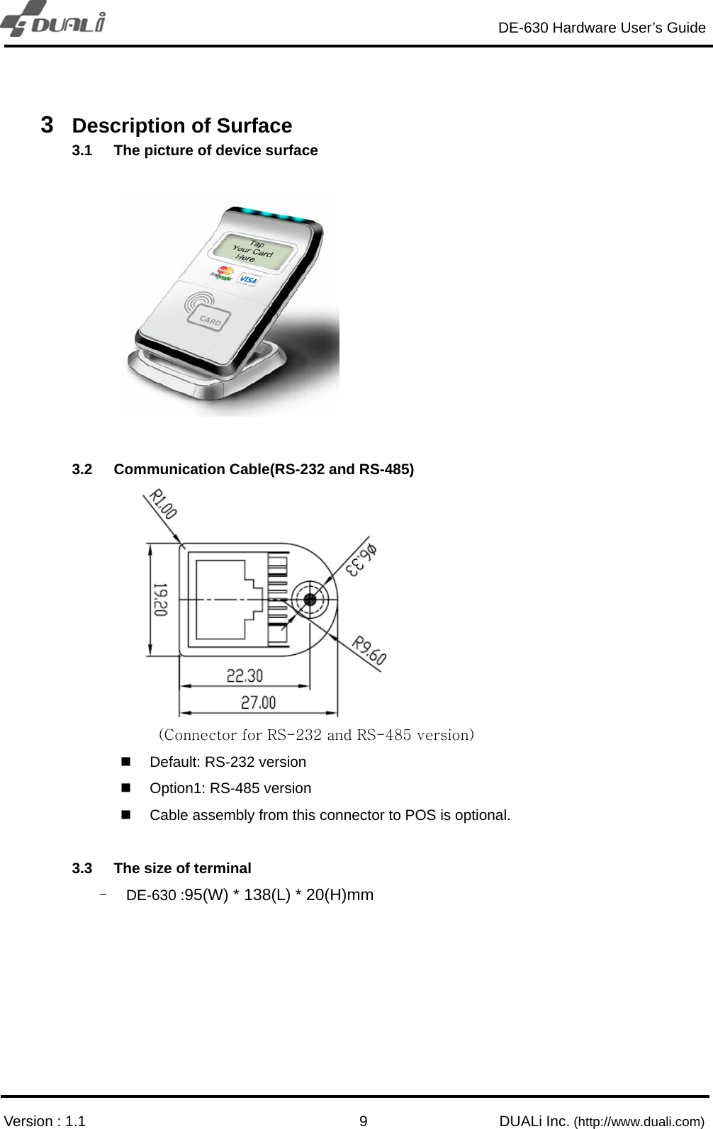
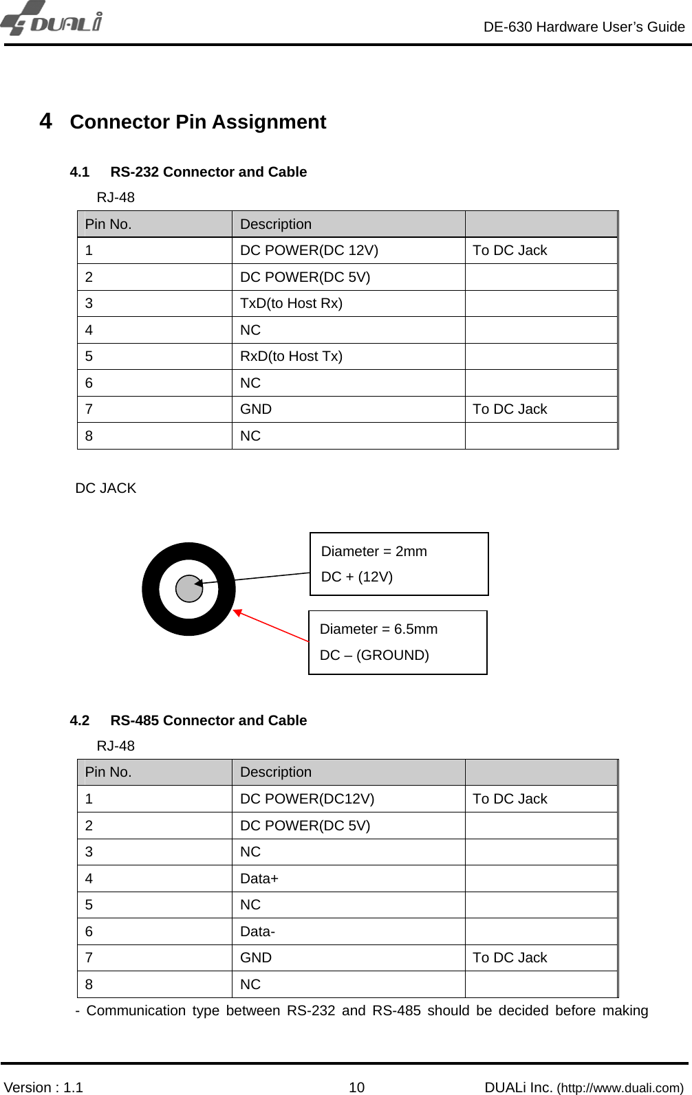
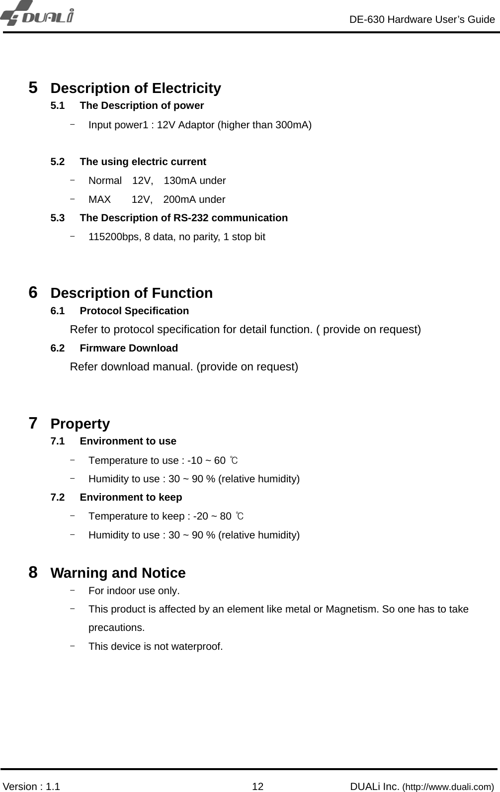
Users Manual
Navigation menu
Upload a User Manual
Namespaces
Wiki Guide
HTML
PDF
Info
Views
User Manual
Discussion / Help
Navigation