Duali DE-630 SMART CARD READER User Manual DE630 user guide
Duali Inc. SMART CARD READER DE630 user guide
Duali >
Users Manual

Copyright ⓒ 2009 DUALi Inc. All rights reserved. You are strictly prohibited to copy, disclose, distribute, or use
this document in part or as a whole for any purposes other than those for which this document is disclosed. This
document is copyrighted and contains confidential information and other intellectual property rights of DUALi Inc.
Any unauthorized use, copy, disclosure or distribution constitutes infringement of DUALi’s intellectual property
rights.
DUALi Inc.
Document Version: 1.0
Last Revised Date: 30 Nov. 2010
DE-630 Hardware User’s Manual

DUALi Inc. reserves the right to make changes to its applications or services or to discontinue
any application or service at any time without notice. DUALi provides customer assistance in
various technical areas, but does not have full access to data concerning the use and
applications of customer's products.
Therefore, DUALi assumes no liability and is not responsible for customer applications or
software design or performance relating to systems or applications incorporating DUALi
products. In addition, DUALi assumes no liability and is not responsible for infringement of
patents and/or any other intellectual or industrial property rights of third parties, which may
result from assistance provided by DUALi.
Composition of the information in this manual has been done to the best of our knowledge.
DUALi does not guarantee the correctness and completeness of the details given in this manual
and may not be held liable for damages ensuing from incorrect or incomplete information. Since,
despite all our efforts, errors may not be completely avoided, we are always grateful for your
useful tips.
We have our development center in South Korea to provide technical support. For any technical
assistance can contact our technical support team as below;
Tel: +82 31 213 0074
e-mail : duali@duali.com

DE-630 Hardware User’s Guide
Version : 1.1 DUALi Inc.
(http://www.duali.com)
3
Revision History
2010.11.30(Ver. 1.0) : First Release
2011.04.07(Ver. 1.1) : RJ-48 Pin Configuration Change

DE-630 Hardware User’s Guide
Version : 1.1 DUALi Inc.
(http://www.duali.com)
4
Contents
1 Summary........................................................................................................................5
2 Structure.........................................................................................................................6
2.1 The Structure of equipment....................................................................................6
2.2 The block diagram of DE-630 ................................................................................7
2.3 Description of main Module ...................................................................................8
3 Description of Surface..................................................................................................... 9
3.1 The picture of device surface................................................................................. 9
3.2 Communication Cable(RS-232 and RS-485)...................................................... 9
3.3 The size of terminal............................................................................................9
4 Connector Pin Assignment ............................................................................................10
4.1 RS-232 Connector and Cable........................................................................... 10
4.2 RS-485 Connector and Cable........................................................................... 10
5 Description of Electricity................................................................................................ 12
5.1 The Description of power.....................................................................................12
5.2 The using electric current ....................................................................................12
5.3 The Description of RS-232 communication........................................................... 12
6 Description of Function..................................................................................................12
6.1 Protocol Specification ..........................................................................................12
6.2 Firmware Download ............................................................................................12
7 Property .......................................................................................................................12
7.1 Environment to use .............................................................................................12
7.2 Environment to keep ...........................................................................................12
8 Warning and Notice.......................................................................................................12
DE-630 Hardware User’s Guide
Version : 1.1 DUALi Inc.
(http://www.duali.com)
5
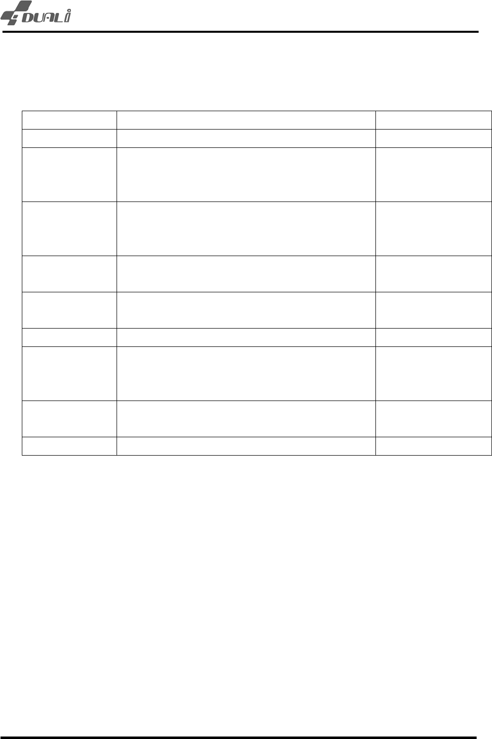
1 Summary
ITEM 사양 비고
CPU STM32F103ZCT6 (ARM Cortex_M3, 144pin) ST
Program Memory 256KBytes FLASH (default)
Up to 8Mbytes external Flash
On chip
Option
(1M,2M,4M,8M)
Data Memory 48KBytes SRAM (default)
Up to 8Mbytes external PSRAM
On chip
Option
(1M,2M,4M,8M)
DISPLAY 4 Status LED
128*64 Graphic LCD (Yellow green)
4 color
Communication RS-232 - default
RS-485 - optional
Decide when order
BUZZER Magnetic Buzzer
RF CARD Frequency : 13.56MHz
Speed : 106,212,424,848Kbps
ISO-14443 A/B ,MIFARE
SAM 4 SAM slots
Class A and B, T=0 and T=1
Input Power Adapter DC 12V (RS-232, RS-485)
DE-630 Hardware User’s Guide
Version : 1.1 DUALi Inc.
(http://www.duali.com)
6
2 Structure
2.1 The Structure of equipment
- DE-630 itself contains all circuits include antenna, 4 SAM connectors.
- User can order RS-232 version or RS-485 version.(Communication Cable is different)
Host PC
(OR)
POS
(RS-232 or RS-485)
(Adaptor)
DE-630 Hardware User’s Guide
Version : 1.1 DUALi Inc.
(http://www.duali.com)
7
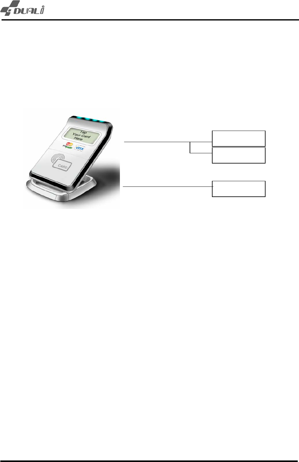
2.2 The block diagram of DE-630
STM32F103
(256Kbytes Flash,
48Kbytes SRAM,
84bytes Battery backup SRAM
POWER
(DC 12V)
Buzzer
RF CHIP(U9)
RC632
ANTENNA
4 * 상태
Battery
Tamper
switch
RS-232 RS-485
LCD(128*64 graphic)
4 * SAM
Nor Flash
PSRAM
13.56
MHz
32.768
kHz
12
MHz

DE-630 Hardware User’s Guide
Version : 1.1 DUALi Inc.
(http://www.duali.com)
8
2.3 Description of main Module
- CPU: 32bit RISC ARM core CPU, It is stm32f103 which is ARM-based 32-bit MCU
with Flash. This CPU has 256Kbyte Flash memory, 48Kbyte SRAM.
- MFRC531 RF IC: This RF IC can control RF card like MIFARE card, type A/B card
simultaneously.
- RS-232 Driver: It’s a Communication part for RS-232 communication.
- RS-285 Driver: It’s a Communication part for RS-485 communication.
- SAM part: It can control 4 SAMs. And each slot can be operated independently.
- LED: It has 4 LEDs to display status of communication and card process.
- LCD : DE-630 has 128*64 graphic LCD Module
- Battery: It maintains RTC and battery backup SRAM while power is not supplied.
- Tamper switch: Erase security memory when case is opened.
- Nor Flash: optional flash memory for non-volatile data.
- PSRAM: optional SRAM for user memory.
DE-630 Hardware User’s Guide
Version : 1.1 DUALi Inc.
(http://www.duali.com)
9
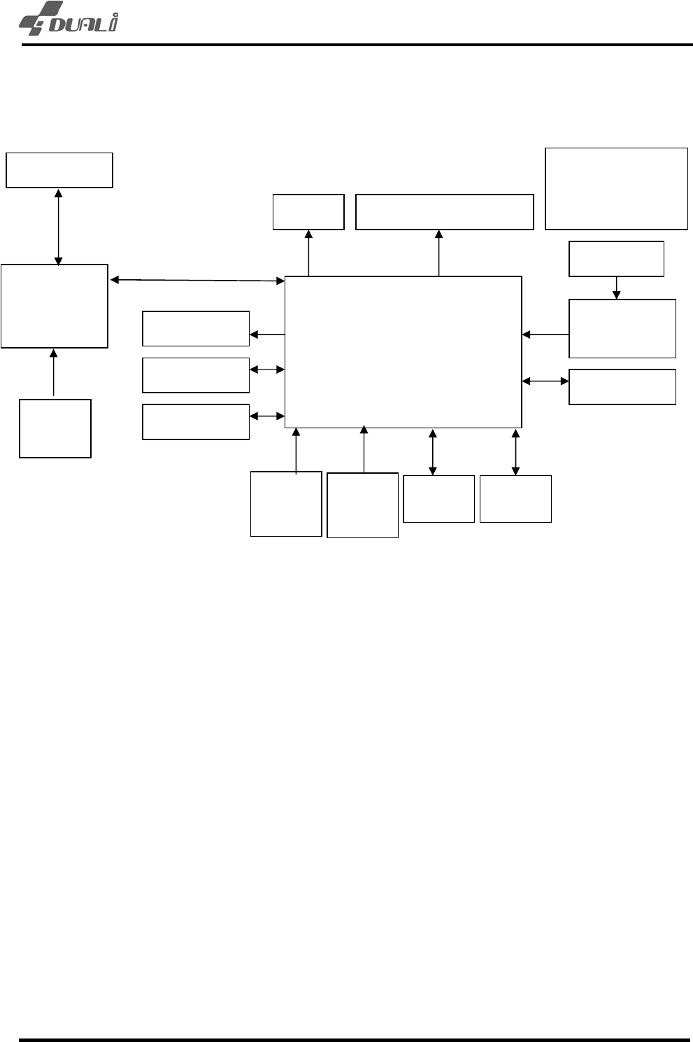
3 Description of Surface
3.1 The picture of device surface
3.2 Communication Cable(RS-232 and RS-485)
(Connector for RS-232 and RS-485 version)
Default: RS-232 version
Option1: RS-485 version
Cable assembly from this connector to POS is optional.
3.3 The size of terminal
- DE-630 :95(W) * 138(L) * 20(H)mm
DE-630 Hardware User’s Guide
Version : 1.1 DUALi Inc.
(http://www.duali.com)
10
4 Connector Pin Assignment
4.1 RS-232 Connector and Cable
RJ-48
Pin No. Description
1 DC POWER(DC 12V) To DC Jack
2 DC POWER(DC 5V)
3 TxD(to Host Rx)
4 NC
5 RxD(to Host Tx)
6 NC
7 GND To DC Jack
8 NC
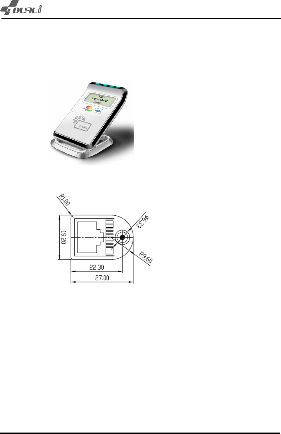
DC JACK
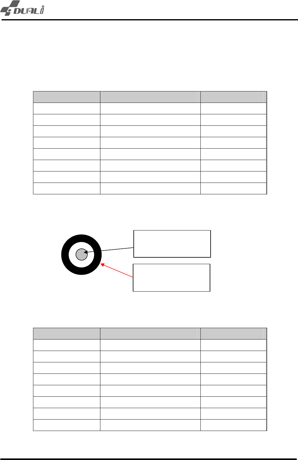
4.2 RS-485 Connector and Cable
RJ-48
Pin No. Description
1 DC POWER(DC12V) To DC Jack
2 DC POWER(DC 5V)
3 NC
4 Data+
5 NC
6 Data-
7 GND To DC Jack
8 NC
- Communication type between RS-232 and RS-485 should be decided before making
Diameter = 2mm
DC + (12V)
Diameter = 6.5mm
DC – (GROUND)

DE-630 Hardware User’s Guide
Version : 1.1 DUALi Inc.
(http://www.duali.com)
11
order.
- Its default communication method is RS-232.
- DC jack’s connection is same with RS-232 version.

DE-630 Hardware User’s Guide
Version : 1.1 DUALi Inc.
(http://www.duali.com)
12
5 Description of Electricity
5.1 The Description of power
- Input power1 : 12V Adaptor (higher than 300mA)
5.2 The using electric current
- Normal 12V, 130mA under
- MAX 12V, 200mA under
5.3 The Description of RS-232 communication
- 115200bps, 8 data, no parity, 1 stop bit
6 Description of Function
6.1 Protocol Specification
Refer to protocol specification for detail function. ( provide on request)
6.2 Firmware Download
Refer download manual. (provide on request)
7 Property
7.1 Environment to use
- Temperature to use : -10 ~ 60 ℃
- Humidity to use : 30 ~ 90 % (relative humidity)
7.2 Environment to keep
- Temperature to keep : -20 ~ 80 ℃
- Humidity to use : 30 ~ 90 % (relative humidity)
8 Warning and Notice
- For indoor use only.
- This product is affected by an element like metal or Magnetism. So one has to take
precautions.
- This device is not waterproof.

DE-630 Hardware User’s Guide
Version : 1.1 DUALi Inc.
(http://www.duali.com)
13
EU
This product is CE marked according to the provision of the R&TTE Directive (99/5/EC).
Here by DUALi Inc. declares that this product is in compliance with the essential requirements and other
relevant provisions of Directive 1999/5/EC.
FCC STATEMENT
CAUTION: Changes or modifications not expressly approved by the party responsible for compliance
could void the user's authority to operate the equipment.
NOTE: This equipment has been tested and found to comply with the limits for a Class B digital device,
pursuant to Part 15 of the FCC Rules. These limits are designed to provide reasonable protection against
harmful interference in a residential installation. This equipment generates, uses and can radiate radio
frequency energy and, if not installed and used in accordance with the instructions, may cause harmful
interference to radio communications. However, there is no guarantee that interference will not occur in a
particular installation. If this equipment does cause harmful interference to radio or television reception,
which can be determined by turning the equipment off and on, the user is encouraged to try to correct the
interference by one or more of the following measures:
-- Reorient or relocate the receiving antenna.
-- Increase the separation between the equipment and receiver.
-- Connect the equipment into an outlet on a circuit different from that to which the receiver is connected.
-- Consult the dealer or an experienced radio/TV technician for help.