Dynabook UPA3459WL 802.11ag Half Size Mini-PCI WLAN Module User Manual 802 11abg manual FCC
Toshiba Corporation 802.11ag Half Size Mini-PCI WLAN Module 802 11abg manual FCC
Dynabook >
Contents
User Manual

802.11a/b/g Combo Mini PCI WLAN Card
User’s Manual
2003 All rights reserved. No part of this document may be reproduced or transmitted in any
form or by any means, electronic or mechanical, for any purpose, without the express written
permission of the seller.
Disclaimer
Information in this document is subject to change without notice. The material contained
herein is supplied without representation or warranty of any kind. The seller therefore assumes
no responsibility and shall have no liability of any kind arising from the supply or use of this
document or the material contained herein.
Trademarks
Microsoft and Windows are registered trademarks of Microsoft Corporation. GUI and
Ethernet is a registered trademark of Xeros Corporation. Atheros and the Atheros logo are
registered trademarks of Atheros Communications, Inc. Cisco, Cisco Systems, and the Cisco
Systems logo are registered trademarks of Cisco Systems, Inc. and/or its affiliates in the U.S.
and certain other countries. All other trademarks mentioned in this document are the property
of their respective owners.
Date: April 2003
Part No. A230XPRev01
I
Contents
Chapter 1 Introduction .................................................................................................................................... 1
Wireless LAN Basics ....................................................................................................................................... 2
Local Area Network (LAN)............................................................................................................................ 2
Wireless Network Topologies........................................................................................................................ 3
802.11a, 802.11b and 802.11g ..................................................................................................................... 6
Chapter 2 Installing the Driver and Utility Software......................................................................................... 7
System Requirements...................................................................................................................................... 8
Installing the driver and software ...................................................................................................................... 8
Chapter 3 Utility Configuration.......................................................................................................................15
Accessing the Atheros Configuration Utility ......................................................................................................15
Note to Windows XP Users..........................................................................................................................16
Network Basic Configuration ...........................................................................................................................17
General Tab ...............................................................................................................................................17
Security Tab...............................................................................................................................................19
Advanced Tab ............................................................................................................................................24
Connecting to an Existing Network ..................................................................................................................27

802.11a/b/g Combo Mini PCI WLAN Card User’s Manual
II
Modifying a Configuration Profile.....................................................................................................................29
Removing a Configuration Profile ....................................................................................................................29
Chapter 4 Checking Status or Statistics.........................................................................................................31
Status Monitor Tray Icon .................................................................................................................................31
Current Status Tab.........................................................................................................................................33
Advanced Status.........................................................................................................................................36
Diagnostics Tab .............................................................................................................................................37
Advanced Statistics.....................................................................................................................................38
Driver Information .......................................................................................................................................40
Chapter 5 ACU Toolbar ..................................................................................................................................43
Action Menu...................................................................................................................................................43
Options Menu.................................................................................................................................................44
Help Menu .....................................................................................................................................................45
Chapter 6 Uninstalling the Wireless LAN Card...............................................................................................47
Chapter 7 Troubleshooting.............................................................................................................................50
Appendix A Setting Up TCP/IP .......................................................................................................................55
For Windows 2000/XP ....................................................................................................................................55

Contents
III

802.11a/b/g Combo Mini PCI WLAN Card User’s Manual
IV
List of Figures
Figure 1-1 Ad Hoc Network ..........................................................................................................................3
Figure 1-2 Infrastructure Network..................................................................................................................4
Figure 1-3 Roaming Across Multiple Access Points........................................................................................5
Figure 3-1 General tab under the Profile Management .................................................................................19
Figure 3-2 Define Pre-Shared Keys screen..................................................................................................21
Figure 3-3 Define User Information screen ..................................................................................................22
Figure 3-4 Security tab under the Profile Management .................................................................................23
Figure 3-5 Advanced tab under the Profile Management ..............................................................................26
Figure 3-6 Available Networks ....................................................................................................................27
Figure 3-7 Selecting Networks....................................................................................................................28
Figure 4-1 Current Status Tab ....................................................................................................................35
Figure 4-2 Advanced Status .......................................................................................................................37
Figure 4-3 Diagnostics Tab.........................................................................................................................38
Figure 4-4 Advanced Statistics...................................................................................................................39
Figure 4-5 Driver Information ......................................................................................................................41
v
About This User’s Manual
This manual was written for Mini PCI Wireless LAN Card. For brevity, throughout this
manual Wireless LAN Card is used to indicate 802.11a/b/g Combo WLAN Card Mini PCI.
Also, the following terms/abbreviations are used interchangeably:
• Access Point-AP
• Wireless LAN-WLAN
• Ethernet network-LAN-network
This User’s Manual contains information on how to install and configure your Wireless LAN
Card. From now on, we will guide you through the correct configuration steps to get your
device up and run.
1
Chapter 1 Introduction
This Wireless LAN Card is an IEEE 802.11a/b/g combo radio solution. Users have the
flexibility to connect to 802.11a, 802.11b or 802.11g networks effortlessly.
The Wireless LAN Card design is based on Atheros WLAN chipset. It supports 802.11a,
802.11b and 802.11g standards to provide maximum data rates of 54 Mbps (802.11a/g) and 11
Mbps (802.11b).

802.11a/b/g Combo Mini PCI WLAN Card User’s Manual
2
Wireless LAN Basics
This section contains some Wireless LAN basics to help you better understand how the
products work together to create a wireless network.
Local Area Network (LAN)
Simply put, a LAN is a network that exists in a relatively limited area. A network is two or
more computers connected together sharing files and peripheral devices such as printers.
The Wireless LAN Card allows you to interact with other computers without having to run
cables normally associated with networks. This lets you move your computer around while
staying connected to your network.
There are two ways to use the Wireless LAN Card. One way is to connect directly to one or
more Wireless LAN Card equipped computers, forming an Ad Hoc wireless network. The
second way is to connect to an Access Point that gives you access to an existing wired LAN,
forming an Infrastructure wireless network.
Error! Style not defined. Error! Style not defined.
3
Wireless Network Topologies
The 802.11 standard defines two wireless modes: Infrastructure mode and Ad Hoc mode.
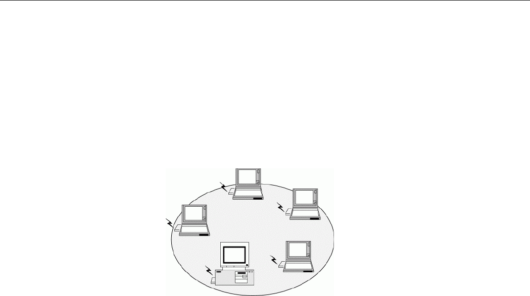
Ad Hoc Network
An Ad Hoc network offers peer to peer connections between wireless stations that are in range
of each other. The stations communicate directly with each other without using an Access
Point or any connection to a wired network. This mode is useful for quickly and easily setting
up a wireless network anywhere that a wireless infrastructure does not exist or is not required
for services. In an Ad Hoc network, all wireless stations must have the same SSID, channel
and WEP keys (if enabled) to communicate with each other.
Figure 1-1 Ad Hoc Network
802.11a/b/g Combo Mini PCI WLAN Card User’s Manual
4
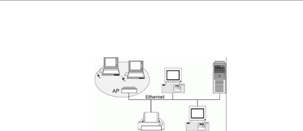
Infrastructure Network
An Infrastructure wireless network consists of at least one Access Point connected to the
wired network infrastructure and a set of wireless end stations. The AP acts as a gateway,
linking the wireless network to a wired LAN. As a result, wireless stations have access to all
of the features of your wired LAN including e-mail, Internet, network printers and files server
access.
Figure 1-2 Infrastructure Network
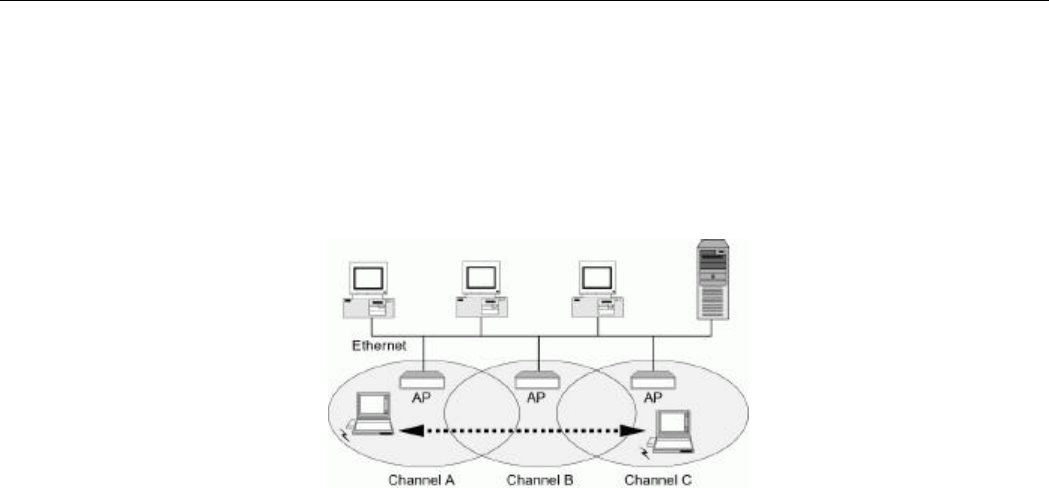
Roaming Between Multiple Access Points
For large environments, multiple Access Points can be implemented to extend the wireless
service coverage area for seamless wireless access. It allows wireless clients to roam from one
AP to another while maintaining the wireless connectivity at all times. A wireless client
Error! Style not defined. Error! Style not defined.
5
wandering across multiple APs will automatically change the operating radio frequency as
required.
In a roaming network, all APs and wireless clients must have the same Service Set Identity
(SSID) and security setting (if enabled). Alternatively the mobile station may use an SSID of
“any” to associate with any available AP, regardless of the AP’s SSID. Roaming among
different Access Points is controlled automatically to maintain the wireless connectivity at all
times.
Figure 1-3 Roaming Across Multiple Access Points

802.11a/b/g Combo Mini PCI WLAN Card User’s Manual
6
802.11a, 802.11b and 802.11g
As this Wireless LAN Card is an IEEE 802.11a/b/g combo radio solution, you can connect to
either an 802.11a, 802.11b or 802.11g network. Getting familiar of some distinguish
differences between these two standards will help you better understand your device.
• Operating Frequency Band
802.11b and 802.11g operate in the 2.4GHz band while 802.11a operates in the 5GHz
band. Therefore, throughout this manual the 2.4 GHz-related terms are referred to
802.11b/g networks while 5 GHz is referred to 802.11a.
• Data Rates
802.11b supports data rates of 1, 2, 5.5, and 11 Mbps.
802.11g supports data rates of 1, 2, 5.5, 6, 9,11, 12, 18, 24, 36, 48 and 54Mbps.
802.11a supports mandatory data rates of 6, 12, and 24 Mbps and optional data rates of
9, 18, 36, and 54 Mbps.
• Modulation
802.11a employs Orthogonal Frequency Division Modulation (OFDM) scheme.
802.11b uses Direct Sequence Spread Spectrum (DSSS) technologies. 802.11g uses
Complementary Code Keying (CCK) and Orthogonal Frequency Division Modulation
(OFDM).

7
Chapter 2 Installing the Driver and Utility Software
This chapter describes the first-time installation of the driver and software for the Wireless
LAN Card. Proper driver installation is to allow the device to operate on your host computer
while the utility software, a Windows program, is to help you configure and mo nitor your
Wireless LAN Card.
Note: As Mini PCI model is an integrated Wireless LAN Card solution, your laptop computer
is probably shipped with its driver and software properly installed. If this is the case, ignore
this chapter and proceed with the configuration steps in the next chapter.
In case you need to re-install the driver and software for any reason, we recommend that you
remove any previously installed driver and software from your system first. Refer to the
section “Chapter 6 Uninstalling the Wireless LAN Card” for the instructions on how to
remove previous driver releases.

802.11a/b/g Combo Mini PCI WLAN Card User’s Manual
8
System Requirements
To use the Wireless LAN Card, your computer must meet the following minimum
requirements:
n Windows 98/Me/2000/XP
n 32 MB of RAM or greater
n 300 MHz processor or higher
n UL listed I.T.E. computers
Installing the driver and software
If your operation system has not been installed with the Wireless LAN Card driver, the
Windows Plug-and-Play capability will automatically detect the new device (e.g., Ethernet
Controller) and display the wizard requesting for drivers. Click Cancel to bypass the wizard
screen and then take out the steps below.
1. Close all Windows programs that are running.
2. Insert the provided Software Utility CD into your CD-ROM drive. Run Setup.exe from
the Software Utility CD to launch the setup program.
3. When the Atheros Install Program screen appears, click Next.

Error! Style not defined. Error! Style not defined.
9
802.11a/b/g Combo Mini PCI WLAN Card User’s Manual
10
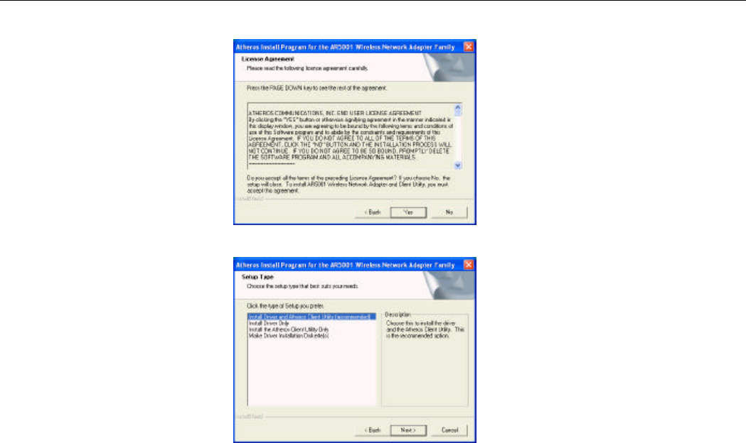
4. Click Yes to accept the license agreement.
5. For first-time installation, select the first option as shown below then click Next.
Error! Style not defined. Error! Style not defined.
11
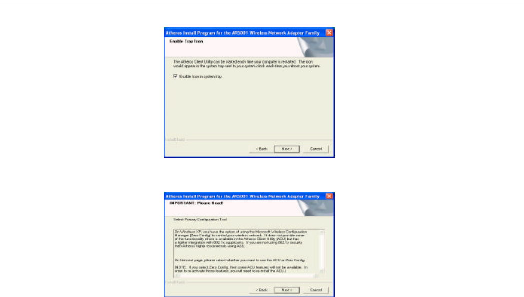
6. Let Enable icon in system tray check box selected. Click Next.
7. Read the following instructions about the utility (ACU or ZERO) you want to use to control
your Wireless LAN Card. Click Next to continue.
802.11a/b/g Combo Mini PCI WLAN Card User’s Manual
12
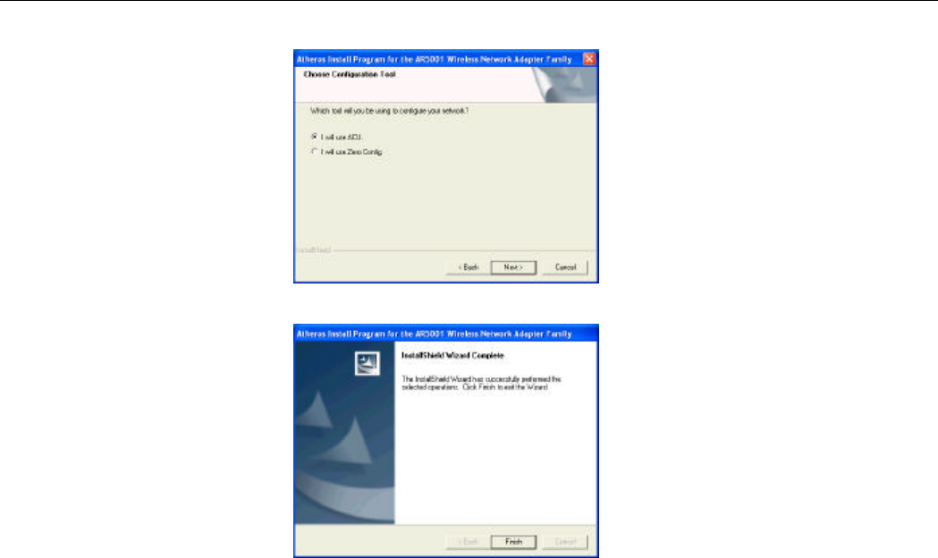
8. Select the preferred utility then click Next.
9. Click Finish to complete the installation and reboot your computer.

Error! Style not defined. Error! Style not defined.
13
Depending on your operating system, following situation may occur during the
installation:
• For Windows XP: When Found New Hardware Wizard appears, have Install the
software automatically selected and follow the on-screen instructions to proceed. If
digital signature message appears, just click Continue Anyway.
Now you are done with the installation procedure. Proceed to next chapter to configure or
fine-tune your Wireless LAN Card settings.
Note: If you need to set up the TCP/IP properties of your Wireless LAN Card, refer to
“Appendix A Setting Up TCP/IP” for details.

15
Chapter 3 Utility Configuration
The configuration of the Wireless LAN Card is done through the Atheros Client Utility
(ACU). The user-mode utility also includes a number of tools to display current statistics and
status information pertaining to your Wireless LAN Card. The Atheros Client Utility screen
pops up with three available tabs: Current Status, Profile Management, and Diagnostics.
This chapter will focus on the Station Configuration tab to guide you through the
configuration tasks. For description of other tabs, please refer to “Chapter 4 Checking Status
or Statistics”.
Accessing the Atheros Configuration Utility
You can access the Atheros Client Utility by any of the following methods:
• Double-click the Atheros Client Utility tray icon on the system tray.
Atheros wireless tray icon

802.11a/b/g Combo Mini PCI WLAN Card User’s Manual
16
Note: If the tray icon is not launched, you can manually start the utility tray icon by
selecting Start > Programs > Atheros > Atheros Client Utility.
• Right-click the ACU tray icon and select Launch Client Utility… from the context
menu.
Note to Windows XP Users
Windows XP provides built-in Wireless Zero Configuration Utility for wireless network.
The utility is enabled by default. When it is active, it will override the Network Name,
Security and other settings of the Atheros Client Utility.
If you want to disable the Windows XP Wireless Zero Configuration Utility and have your
device managed only by the Atheros Client Utility, proceed as follows:
1. Double-click the Windows XP wireless tray icon and then click Advanced (or
Properties) > Wireless Networks.

Error! Style not defined. Error! Style not defined.
17
2. On the Wireless Networks tab, uncheck the Use Windows to configure my wireless
network settings box and click OK.
If you need to revert back to using Windows XP Wireless Zero Configuration Utility, just
go to the Wireless Networks tab and check the Use Windows to configure my wireless
network settings box and click OK.
Network Basic Configuration
To add a new Ad Hoc or Infrastructure profile, click New on the Profile Management tab.
The dialog box displays three tabs: General, Security and Advanced.
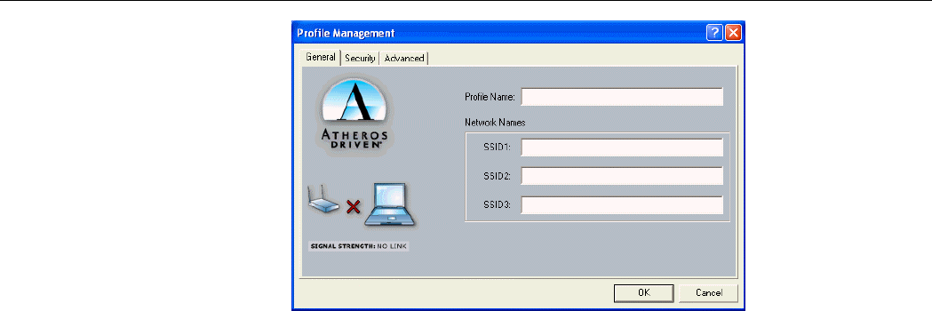
General Tab
The configuration items on the General tab are described as below.
Atheros wireless icon
Windows XP wireless icon

802.11a/b/g Combo Mini PCI WLAN Card User’s Manual
18
Profile Name: Enter a unique name to identify this network setting. Configuration names are
not case sensitive.
Network Names (SSID):
• Ad Hoc mode: It is the name of the Wireless LAN group you want to create or
participate in. This field has a maximum limit of 32 characters. A network name is
mandatory for Ad Hoc mode. The SSID for all stations in a single Ad Hoc network
must be the same. Enter only one SSID.
• Infrastructure mode: It is the name of the Wireless LAN group you want to participate
in. This field has a maximum limit of 32 characters. You can enter up to three SSID. In
an Infrastructure network, the SSID must match on AP and all the wireless clients to
communicate with each other.
Note that under Access Point mode, if the Network Name (SSID) field is left blank or
filled in with the special SSID name “any”, your Wireless LAN Card will connect to
the first compatible and “open” AP with the best signal strength within the connection
range. It allows your Wireless LAN Card to wander across networks with different
SSID.
Error! Style not defined. Error! Style not defined.
19
Figure 3-1 General tab under the Profile Management
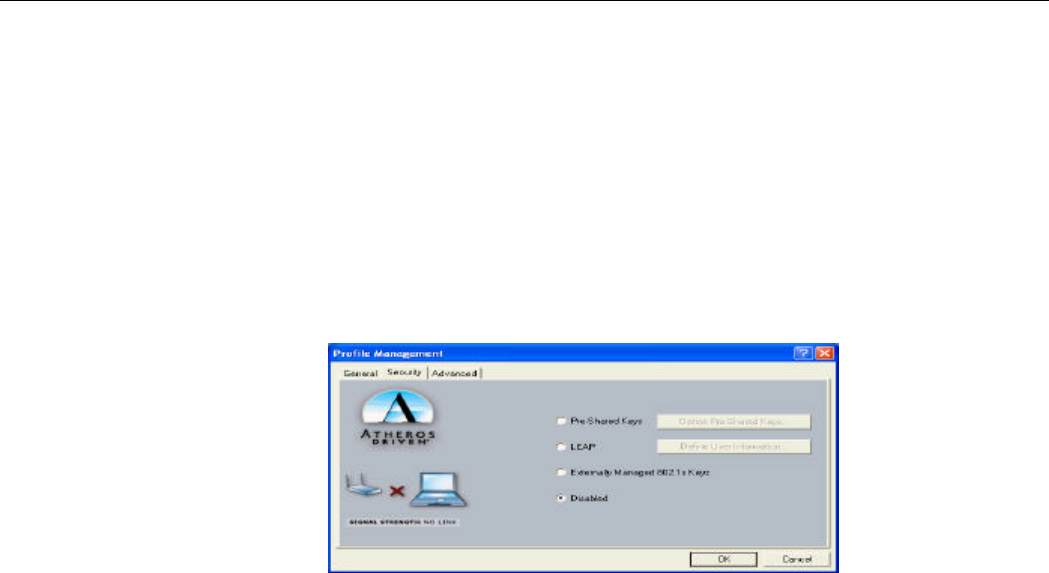
Security Tab
The Atheros Client Utility provides four types of encryption: Pre-Shared Keys, LEAP,
Externally Managed 802.1x Keys and Disabled.
Each wireless device within a WLAN must use the same security settings to allow
communication. Depending on whether you are connecting to an Ad Hoc or Infrastructure
network, you will need to consult one of the workgroup participants or network administrator
for the correct security settings.

802.11a/b/g Combo Mini PCI WLAN Card User’s Manual
20
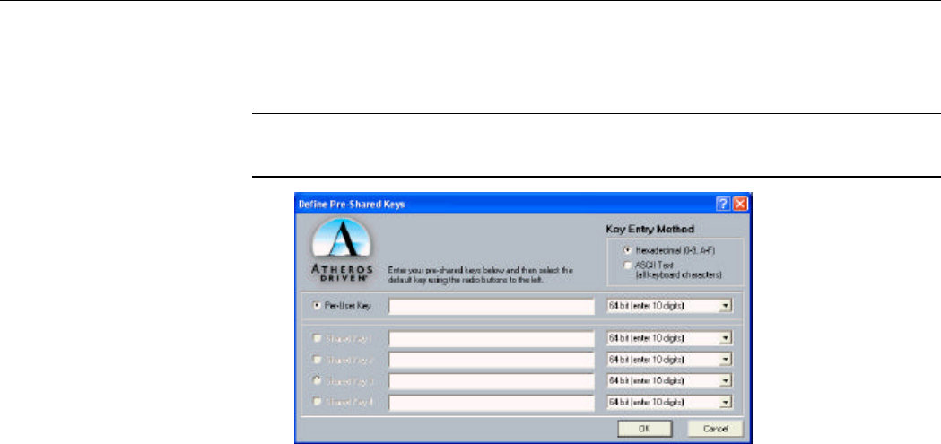
Pre-Shared Keys
To use this option, enable the Pre-Shared Keys option on the Security tab and click Define
Pre-Shared Keys to set the encryption keys. Then configure the fields below:
Key Entry Method: Select the method to enter the key. If Hexadecimal is selected, only
digits 0-9 and letters a-f, A-F are allowed. If ASCII Text is selected, you can enter
alphanumeric characters.
Key Length (bit): Defines the length for each encryption key. Key length varies according to
the WEP type. As the Key Length is changed, the number of available characters in the field is
changed automatically. If an already entered key is too long, the key is automatically truncated
to fit. If the key length is increased again, the field does not automatically restore to its
previous value.
Per-User Key: Defines the unique encryption key for network configuration security. This
field must be populated to enable security using a unique key. This key is not used in Ad Hoc
mode.
Shared Keys (1 ~ 4): Defines a set of shared encryption keys for network configuration
security. At least one Shared Key field must be populated to enable security using a shared
key.
Note: All encryption key fields are displayed only when initially entered. On subsequent entry
into the security property page, the field are masked.
Error! Style not defined. Error! Style not defined.
21
Select the default encryption keys to be used (either Per-User Key or Shared Key). You are
only allowed to select one Per-User Key, or one Shared Key 1, Shared Key 2, Shared Key
3, or Shared Key 4 whose corresponding field has been completed.
Note: Currently, Windows XP does not support 152-bit encryption when using the built-in
Wireless Zero Configuration Utility. You must disable the zero configuration in order to use
152-bit encryption.
Figure 3-2 Define Pre-Shared Keys screen
802.11a/b/g Combo Mini PCI WLAN Card User’s Manual
22
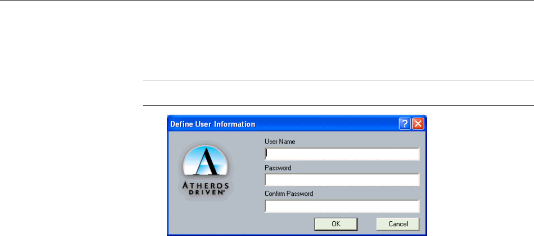
LEAP (Light Extensible Authentication Protocol)
Enables the use of LEAP for dynamic security keys. If you want to connect to a network using
Cisco LEAP, make sure to check the LEAP option and enter the User Name and Password
used to log in to the network in the provided fields.
Note: If you are going to connect to an LEAP network, you should disable Windows XP
Wireless Zero Configuration Utility entirely because it is basically incompatible with LEAP.
Figure 3-3 Define User Information screen
Error! Style not defined. Error! Style not defined.
23
Externally Managed 802.1x Keys
Windows XP provides native support for 802.1x standard. Its Wireless Zero Configuration
Utility allows to set up 802.1x related parameters. However, to use 802.1x function, your
wireless station also needs some essential components, such as a certificate from the
certificate authority. Please consult with the network administrator for the configuring
procedures.
If you are using a operating system other than Windows XP, the Define Static Encryption
Keys button is available for you to enter at least one key into the Atheros Client Utility static
key configuration. In the AP-802.1x network, the static keys serve only to initialize the
security data structures. Real keys are dynamically provided by 802.1x key distribution
protocol.
Figure 3-4 Security tab under the Profile Management

802.11a/b/g Combo Mini PCI WLAN Card User’s Manual
24
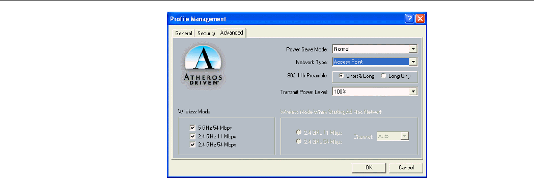
Advanced Tab
The configuration items on the Advanced tab are described as below.
Power Save Mode: Infrastructure mode ONLY. This feature reduces power consumption by
the Wireless LAN Card to extend the battery life of your computer. The options include Off,
Normal and Maximum.
• Off – The power management is disabled and the card consumes full power from the
computer.
• Normal – The driver turns off power to the adapter for brief periods over briefly
spaced time intervals.
• Maximum – The driver turns off power to the adapter for longer periods over more
widely spaced time intervals.
The guideline for choosing Normal or Maximum:
• The card wakes up more often and responds sooner to network requests in Normal
mode than in Maximum mode.
• Maximum mode consumes less power than Normal mode.
Network Type: Select Ad Hoc or Access Point.
802.11b Preamble: The preamble is part of the IEEE 802.11b physical layer specification. All
802.11b devices are mandatory to support the long preamble format, but may optionally

Error! Style not defined. Error! Style not defined.
25
support the short preamble. This Wireless LAN Card supports the short preamb le. The default
Short & Long option allows communication with other 802.11b devices which support short
preamble to boost the throughput. If your device is having trouble to communicate with other
802.11b devices, you may try to select the Long Only option.
Transmit Power Level: Specifies the transmit power to be used. Reducing the transmit power
level conserves battery power but decreases radio range.
Wireless Mode: Specifies the wireless operation mode. The Wireless LAN Card will scan the
radio signals only in the base band you specified. You can check all for your convenience.
• 5 GHz 54 Mbps: Specifies whether to use 54 Mbps mode for 802.11a radio space.
• 2.4 GHz 11 Mbps: Specifies whether to use 11 Mbps mode for 802.11b radio space.
• 2.4 GHz 54 Mbps: Specifies whether to use 54 Mbps mode for 802.11ga radio space.
Wireless Mode When Starting Ad Hoc Network: Disabled in Infrastructure mode. Set up
the operational mode of your Ad Hoc Network. Select the Channel (1~11 or Auto) and
choose the base band:
• 2.4 GHz 11 Mbps: Specifies whether to use 11 Mbps mode for 802.11b radio space.
• 2.4 GHz 54 Mbps: Specifies whether to use 54 Mbps mode for 802.11ga radio space.
802.11a/b/g Combo Mini PCI WLAN Card User’s Manual
26
Figure 3-5 Advanced tab under the Profile Management
Error! Style not defined. Error! Style not defined.
27
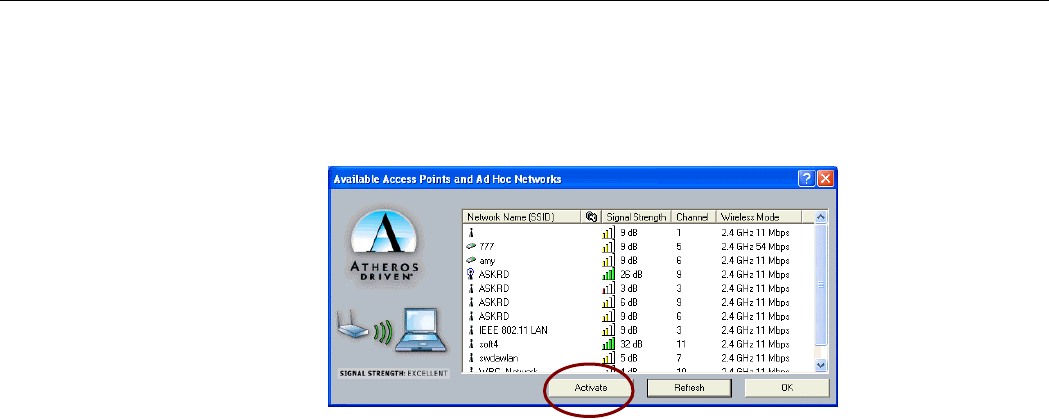
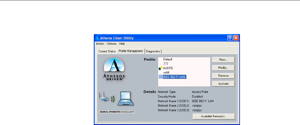
Connecting to an Existing Network
To check for existing networks near your computer, open the Profile Management tab and
click Available Networks… button, the following screen will pop-up.
Figure 3-6 Available Networks
All available networks will be shown in the above list box. Highlight the network name
(SSID) you wish to join in and click the Activate button. If no configuration profile exists for
the selected network, the General tab under Profile Management will pop. Enter a name for
the selected network in the Profile Name field and click OK to return to the Profile
Management tab.
802.11a/b/g Combo Mini PCI WLAN Card User’s Manual
28
In the Profile list box highlight the profile name and in Details section will appear
information about the selected profile. To get connected, double-click on the profile name or
highlight the profile name and click Activate button.
Figure 3-7 Selecting Networks
Another way to switch the profile is to right-clicking the ACU tray icon and select
Configuration Profile … from the context menu. Another menu will appear, click on the
profile you wish to connect to.
29
Modifying a Configuration Profile
To modify a configuration profile, highlight the profile name from the Profile list box and
click the Modify button.
Removing a Configuration Profile
To remove a configuration profile:
1. Highlight the profile to remove from the Profile list on the Station Configuration tab.
2. Click the Remove button.

31
Chapter 4 Checking Status or Statistics
The Atheros Client Utility includes a number of options to display statistics and status
information. These tools can be accessed via the corresponding tabs of the Atheros Client
Utility.
Status Monitor Tray Icon
The Atheros Client Utility tray icon allows you to easily and quickly monitor your wireless
connection status. The tray icon shows the signal strength using colors and the received signal
strength indication (RSSI).

802.11a/b/g Combo Mini PCI WLAN Card User’s Manual
32
The number (2.4 or 5) indicates the current wireless base band. The colors and the signal
strength are defined as follows:
Color Quality RSSI (dBm)
Green Excellent 20 dBm +
Yellow Good 10-20 dBm
Orange Poor <10 dBm
Red No Link No connection
You can hold the mouse cursor over the tray icon to display transmit and receive speed and the
current configuration profile name.
When the RF signal of the Wireless LAN Card is disabled, the icon would appear as follows:

Error! Style not defined. Error! Style not defined.
33
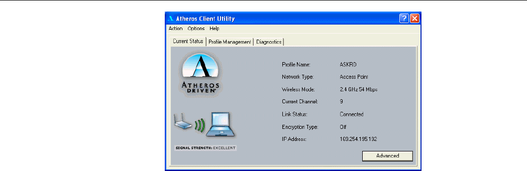
Current Status Tab
The Current Status tab of the Atheros Client Utility contains general information about the
program and its operations.
The following table describes the items found in the Current Status tab.
Screen Item Description
Profile Name The name of the current configuration.
Network Type Displays if the adapter is connected to an Access Point or Ad
Hoc network.
Wireless Mode Displays the connection frequency and maximum speed:
l 5 GHz 54 Mbps (802.11a)
l 2.4 GHz 54 Mbps (802.11g)
l 2.4 GHz 11 Mbps (802.11b
Current Channel Display the currently selected channel..
Link Status Shows whether the station is connected to a wireless network.

802.11a/b/g Combo Mini PCI WLAN Card User’s Manual
34
Screen Item Description
Encryption Type Displays the current security mode:
l WEP – use only WEP encryption.
l AES (Advanced Encryption Security) – only associate with
Access Points that supports AES encryption.
l CKIP – Cisco Key Integrity Protocol
l Off – No encryption is used.
IP Address Displays the IP address of the station.
Error! Style not defined. Error! Style not defined.
35
Figure 4-1 Current Status Tab

802.11a/b/g Combo Mini PCI WLAN Card User’s Manual
36
Advanced Status
You can view advanced information about the program and its operation by clicking the
Advanced button on the Current Status tab.
The following table describes the items found on the Advanced Status screen.
Screen Item Description
Country The regulatory domain of the network.
Transmit Power Level Displays the transmit power level.
Network Name (SSID) The wireless network name.
Power Save Mode The power management options. Power management is
disabled in Ad Hoc mode.
Frequency The frequency the station is using.
Transmit Rate Displays the transmit rate for the current connection.
Receive Rate Displays the receive rate for the current connection.

Error! Style not defined. Error! Style not defined.
37
Figure 4-2 Advanced Status
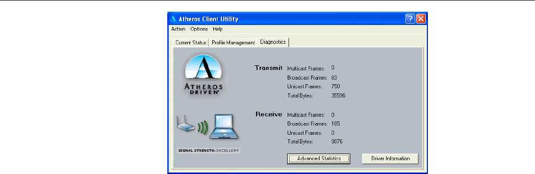
Diagnostics Tab
The Diagnostics tab lists the following receive and transmit diagnostics for frames received
by or transmitted by the wireless network adapter.
• Multicast frames transmitted and received
• Broadcast frames transmitted and received
• Unicast frames transmitted and received
• Total bytes transmitted and received
802.11a/b/g Combo Mini PCI WLAN Card User’s Manual
38
Figure 4-3 Diagnostics Tab
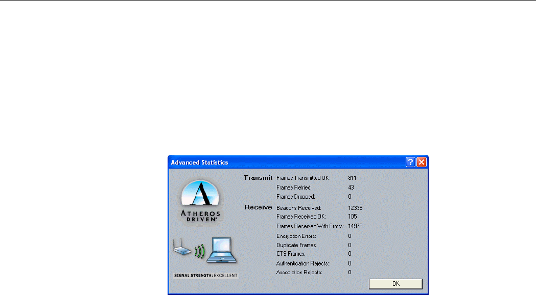
Advanced Statistics
Advanced Statistics also show receive and transmit statistical information for the following
receive and transmit diagnostics for frames received by or transmitted to the wireless network
adapter.
• Frames transmitted OK
• Frame retried
Error! Style not defined. Error! Style not defined.
39
• Frames dropped
• Beacons received
• Frames received with errors
• Encryption errors
• Duplicate frames
• CTS frames
• Authentication rejects
• Association rejects
Figure 4-4 Advanced Statistics

802.11a/b/g Combo Mini PCI WLAN Card User’s Manual
40
Driver Information
The Driver Information contains general information about the network interface card (NIC)
and the network driver interface specification (NDIS).
The following table describes the items found on the Driver Information tab.
Screen Item Description
Card Name The name of the NIC.
MAC Address The station's MAC address. It is configured at the factory.
Driver The location of the NDIS driver.
Driver Version The NDIS driver version.
Driver Date Date of the NDIS driver release.

Error! Style not defined. Error! Style not defined.
41
Figure 4-5 Driver Information
43
Chapter 5 ACU Toolbar
There are three menus Action, Options, Help in the ACU toolbar, check the appropriate
section for more information.
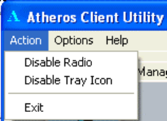
Action Menu
You can enable/disable radio frequency or ACU icon in the system tray. Click Exit to
shutdown the utility.

802.11a/b/g Combo Mini PCI WLAN Card User’s Manual
44
Options Menu
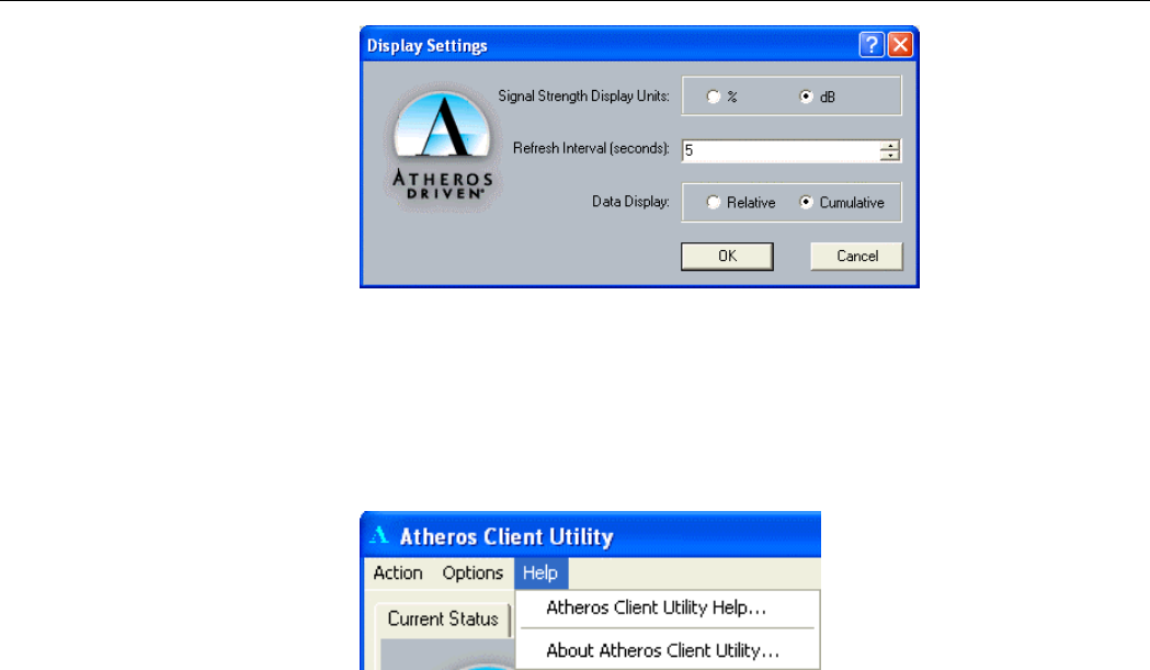
There is only one option under this menu. You can view or change the current display settings.
To change the display settings, click on Display Settings…. The display settings dialog box
contains tools to set these parameters:
Signal Strength Display Units: Sets the units used when displaying signal strength:
percentage or decibels.
Refresh Interval (seconds): Sets the display refresh interval in seconds.
Data Display: Sets the display to cumulative or relative.
• Relative: Displays the change (delta) in statistical data since the last update.
• Cumulative: Displays statistical data collected from the beginning of driver load.
Error! Style not defined. Error! Style not defined.
45
Figure 5-6 Display Settings
Help Menu
This menu contains Atheros Client Utility Help in web format and About Atheros Client
Utility.
47
Chapter 6 Uninstalling the Wireless LAN Card
Should you need to uninstall the Wireless LAN Card and its application software for any
reason, please proceed as follows.
The uninstallation procedures are basically the same under Windows 98, Me, 2000 and XP.
The graphics here assume a Windows XP environment.
1. Close all programs that are currently running.
2. Right-click on the Atheros Client Utility (ACU) icon in the system tray. Click Exit to
shut down the utility.
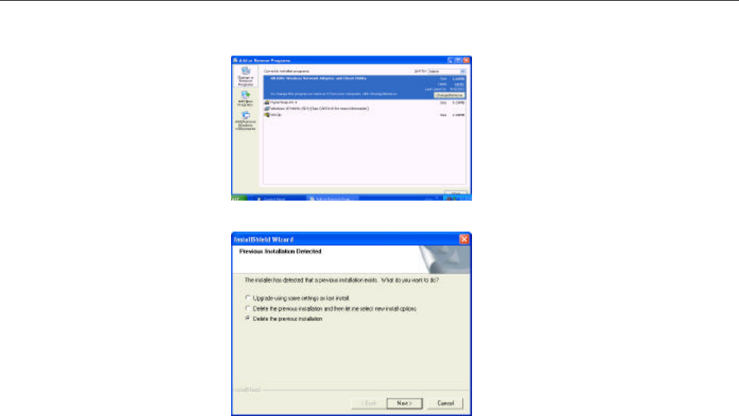
3. Select Start > Settings > Control Panel. Double-click the Add or Remove Programs
icon.
802.11a/b/g Combo Mini PCI WLAN Card User’s Manual
48
4. Highlight AR5001 Wireless Network Adapter and Client Utility then click
Change/Remove.
5. Select Delete the previous installation and click Next.
Error! Style not defined. Error! Style not defined.
49
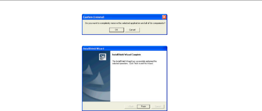
6. When confirm message appears, click OK.
7. Click Finish.

802.11a/b/g Combo Mini PCI WLAN Card User’s Manual
50
Chapter 7 Troubleshooting
My station cannot associate in Ad Hoc mode.
Make sure all the stations in the Ad Hoc network are set with the same SSID. You can set up
one station to start the Ad Hoc network and wait briefly before setting other stations. This
prevents several stations from trying to establish a network at the same time, which can result
in multiple singular networks being established, rather than a single network with multiple
stations associated to it.
If you are in the Europe using ETSI regulatory domain, Ad Hoc mode is not supported.
My station cannot access network resources in Infrastructure mode.
Even your link status indicates a successful connection with the Access Point, this connection
applies to the “physical” network layer only. It is just like pulling a cable between two wired
computers. To access the network resource, you will need a login name and login password as
implemented by most of network operating systems. You should consult with your network
administrator for required settings.

Error! Style not defined. Error! Style not defined.
51
Radio Interference
You may be able to eliminate any interference by trying the following:
• Increase the distance between the wireless computers and the device causing the radio
interference.
• Plug the computer equipped with the Wireless LAN Card into an outlet on a different
branch circuit from that used by the affecting device.
• Consult the dealer or an experienced radio technician for help.
• For 802.11b connection, keep the computer with the Wireless LAN Card away from
the microwave oven and large metal objects.
Cannot Connect to Another Wireless LAN Card
If you cannot make a connection to another Wireless LAN Card from your computer, it could
be due to one of the following reasons:
• Incorrect SSID. Make sure the SSID is the same for all computers that have a Wireless
LAN Card.
• Changes are not being recognized by your computer. Restart your computer.

802.11a/b/g Combo Mini PCI WLAN Card User’s Manual
52
• If in Ad Hoc mode, make sure the Log on to Windows NT domain check box is not
selected in the Client for Microsoft Networks Properties dialog box in the Network
Configuration tab.
• Incorrect IP address or subnet mask. Check these settings in the TCP/IP Properties
dialog box in the Network Configuration tab.
Poor Link Quality
If the link quality display stays in the poor range, it could be due to one of the following
reasons:
• Radio interference.
• For 802.11b/g 2.4 GHz band, possible sources of interference can be microwave ovens,
cordless phones or pager systems. Identify and eliminate the source of interference.
Although 802.11a 5 GHz band has less interference, the signals have a higher
absorption rate and may be blocked by walls or other building structures. Move your
device closer to your target Access Point or wireless station.
• Distance between Wireless LAN Card and Access Point is too far. Decrease the
distance between the Access Point or another wireless adapter.
Cannot Connect to an Access Point

Error! Style not defined. Error! Style not defined.
53
If you cannot make a connection to an Access Point, it could be due to one of the following
reasons:
• Make sure the Wireless LAN Card and the Access Point have no physical connection
problems.
• Make sure the SSID for the Wireless LAN Card is the same as the Access Point.
• Make sure the security setting is the same as that of the Access Point. Also, make sure
the default key is the same for both the Wireless LAN Card and the Access Point.
55
Appendix A Setting Up TCP/IP
This section contains instructions for configuring the TCP/IP protocol of the Wireless LAN
Card. The IP address policy depends on your network. You should configure your TCP/IP
protocol as instructed by your network administrator.
For Windows 2000/XP
1. Double-click Network Dial-up Connections (Windows 2000) or Network Connections
(Windows XP) on Control Panel.
2. Right-click the Local Area Connection icon corresponding to your wireless adapter and
click Properties.
3. On the General tab, highlight Internet Protocol (TCP/IP) and then click Properties.
Option A: Use fixed IP address.
Enable the Use the following IP Address option. Enter the IP address, Subnet Mask
and Default gateway. Then click OK.
Option B: Use dynamic IP address

802.11a/b/g Combo Mini PCI WLAN Card User’s Manual
56
Select Obtain an IP address automatically.
4. Close the Local Area Connection Properties window. For Windows 2000, if prompted,
click Yes to restart your computer.

Appendix A Setting Up TCP/IP
57
Federal Communication Commission Interference Statement
This equipment has been tested and found to comply with the limits for a Class B digital device, pursuant to
Part 15 of the FCC Rules. These limits are designed to provide reasonable protection against harmful
interference in a residential installation. This equipment generates, uses and can radiate radio frequency
energy and, if not installed and used in accordance with the instructions, may cause harmful interference to
radio communications. However, there is no guarantee that interference will not occur in a particular
installation. If this equipment does cause harmful interference to radio or television reception, which can be
determined by turning the equipment off and on, the user is encouraged to try to correct the interference by
one of the following measures:
- Reorient or relocate the receiving antenna.
- Increase the separation between the equipment and receiver.
- Connect the equipment into an outlet on a circuit different from that to which the receiver is connected.
- Consult the dealer or an experienced radio/TV technician for help.
This device complies with Part 15 of the FCC Rules. Operation is subject to the following two conditions: (1)
This device may not cause harmful interference, and (2) this device must accept any interference received,
including interference that may cause undesired operation.
FCC Caution: Any changes or modifications not expressly approved by the party responsible for compliance
could void the user's authority to operate this equipment.

802.11a/b/g Combo Mini PCI WLAN Card User’s Manual
58
IMPORTANT NOTE:
FCC Radiation Exposure Statement:
This equipment complies with FCC radiation exposure limits set forth for an uncontrolled environment. End
users must follow the specific operating instructions for satisfying RF exposure compliance.
For operation within 5.15 ~ 5.25GHz frequency range, it is restricted to indoor environment, and the antenna
of this device must be integral.
This transmitter must not be co-located or operating in conjunction with any other antenna or transmitter.