Dynabook UPA3459WL 802.11ag Half Size Mini-PCI WLAN Module User Manual CRN 29045 Sub notebook 2 of 2
Toshiba Corporation 802.11ag Half Size Mini-PCI WLAN Module CRN 29045 Sub notebook 2 of 2
Dynabook >
Contents
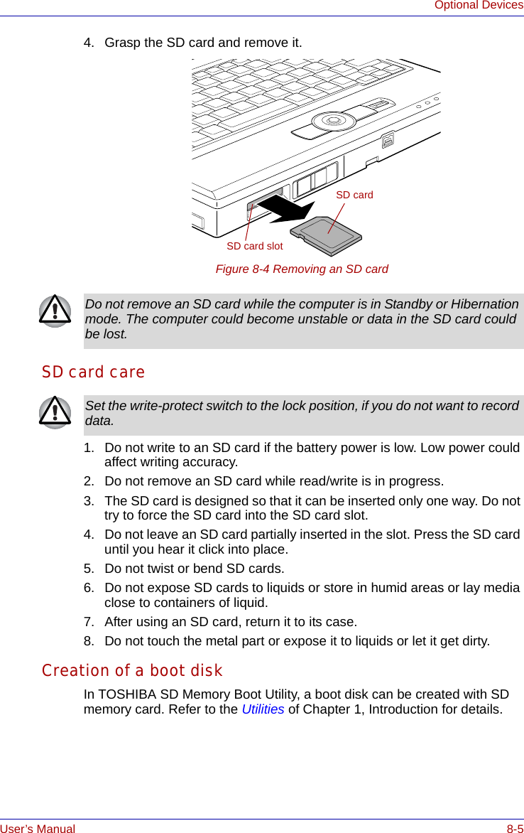
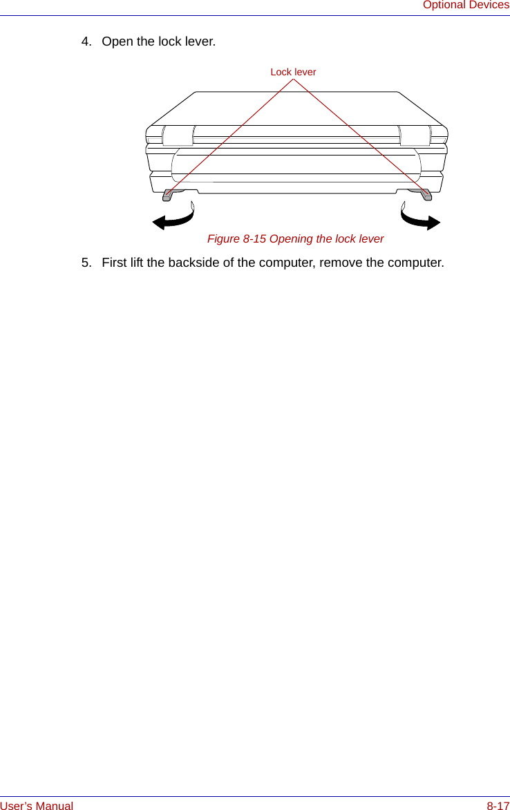
CRN 29045 Sub notebook User manual 2 of 2
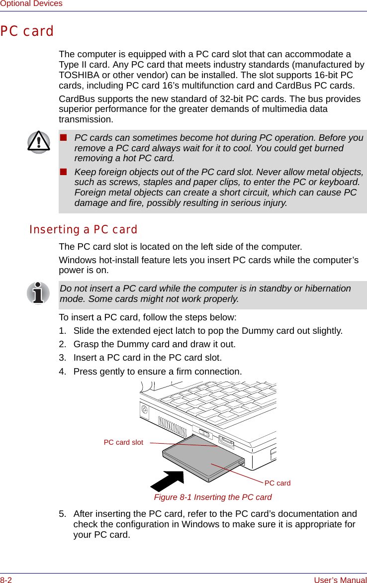
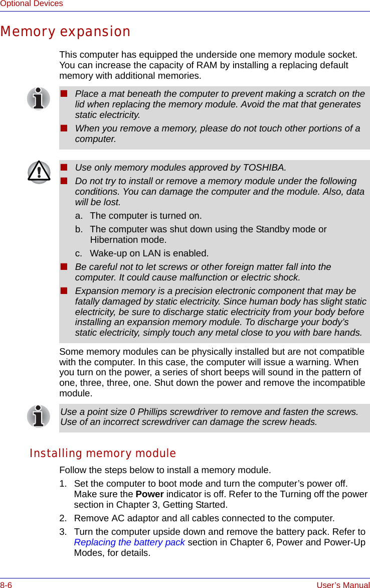
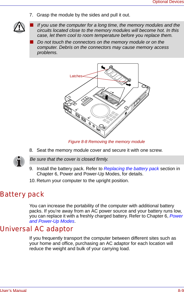
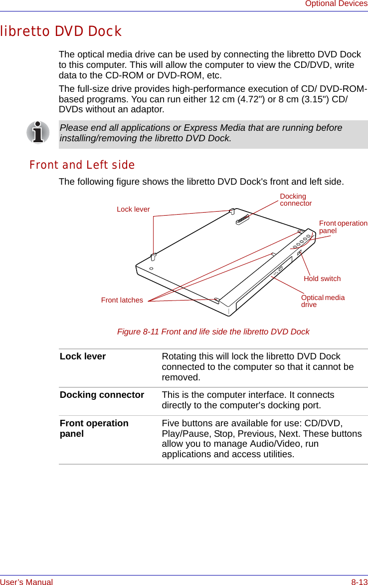

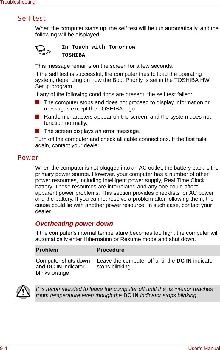
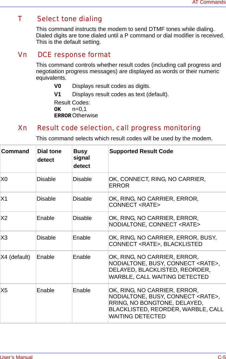
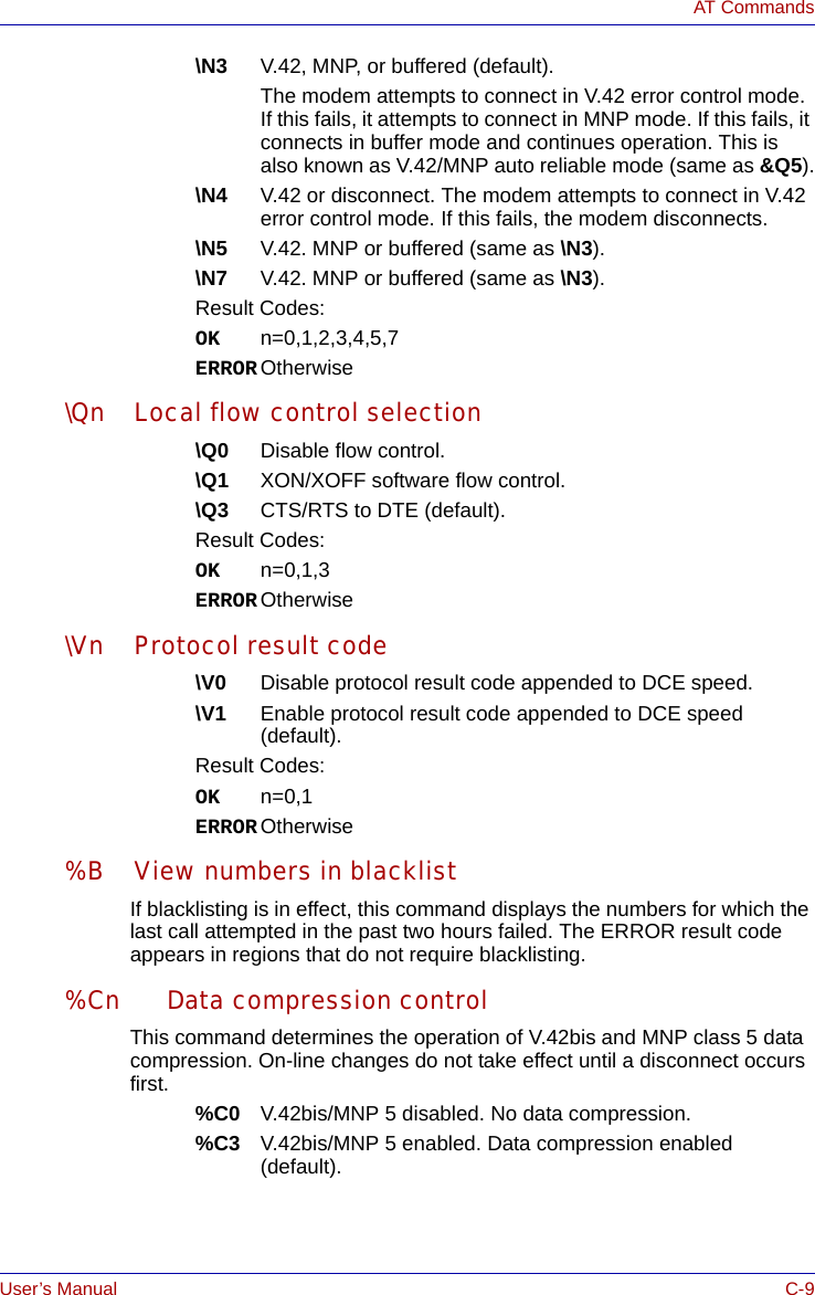
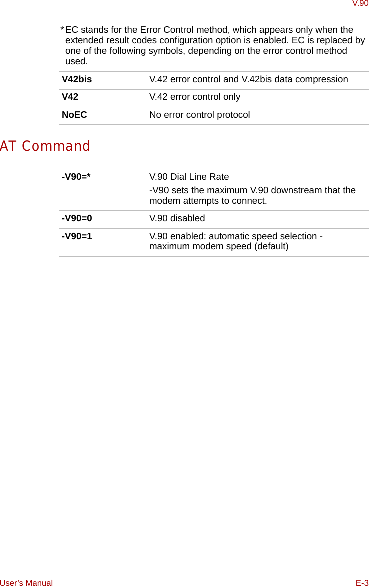
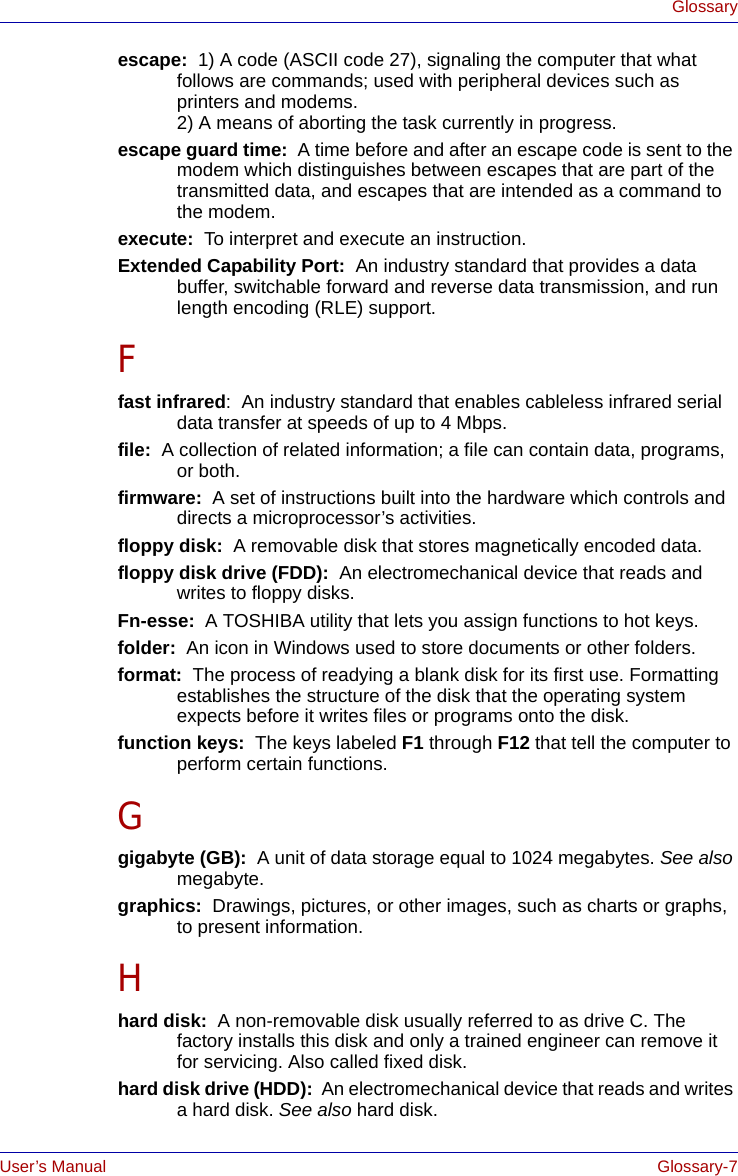
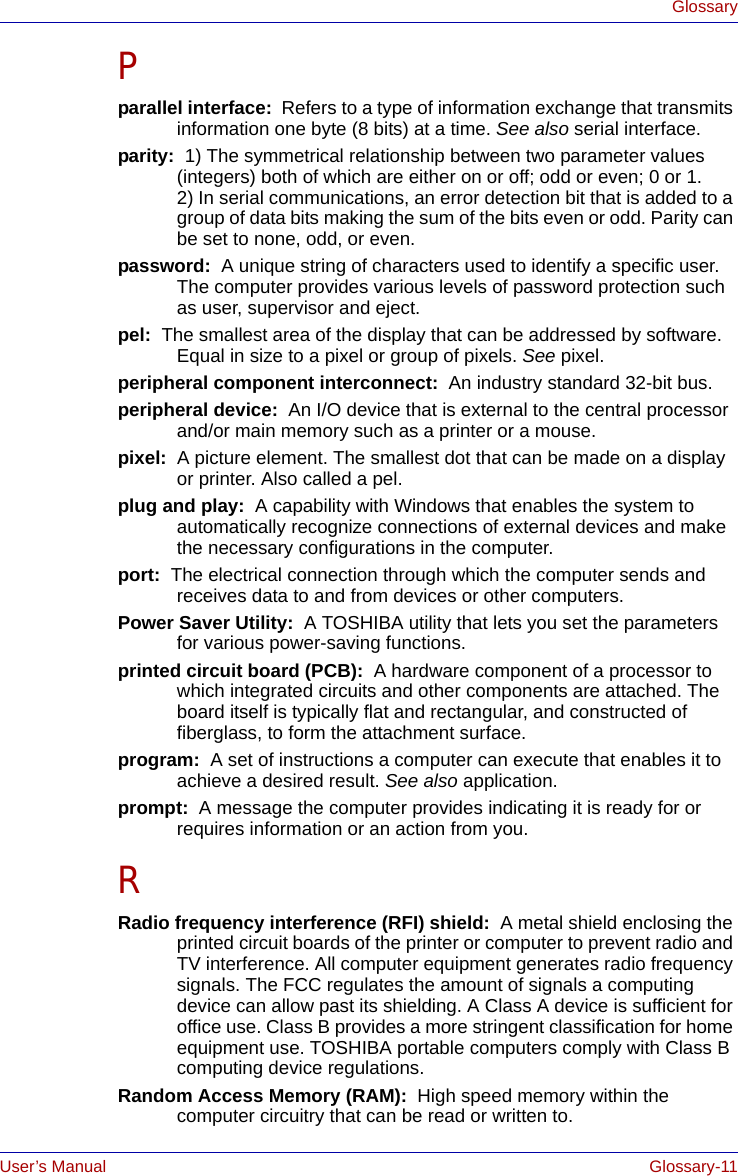
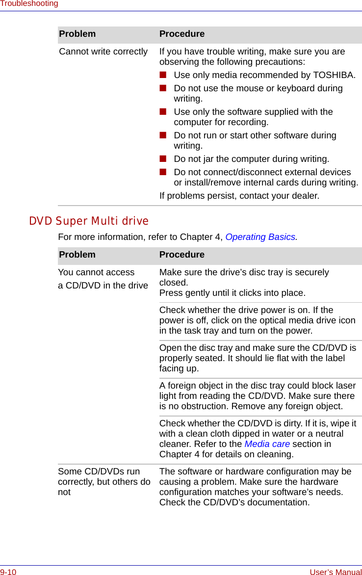
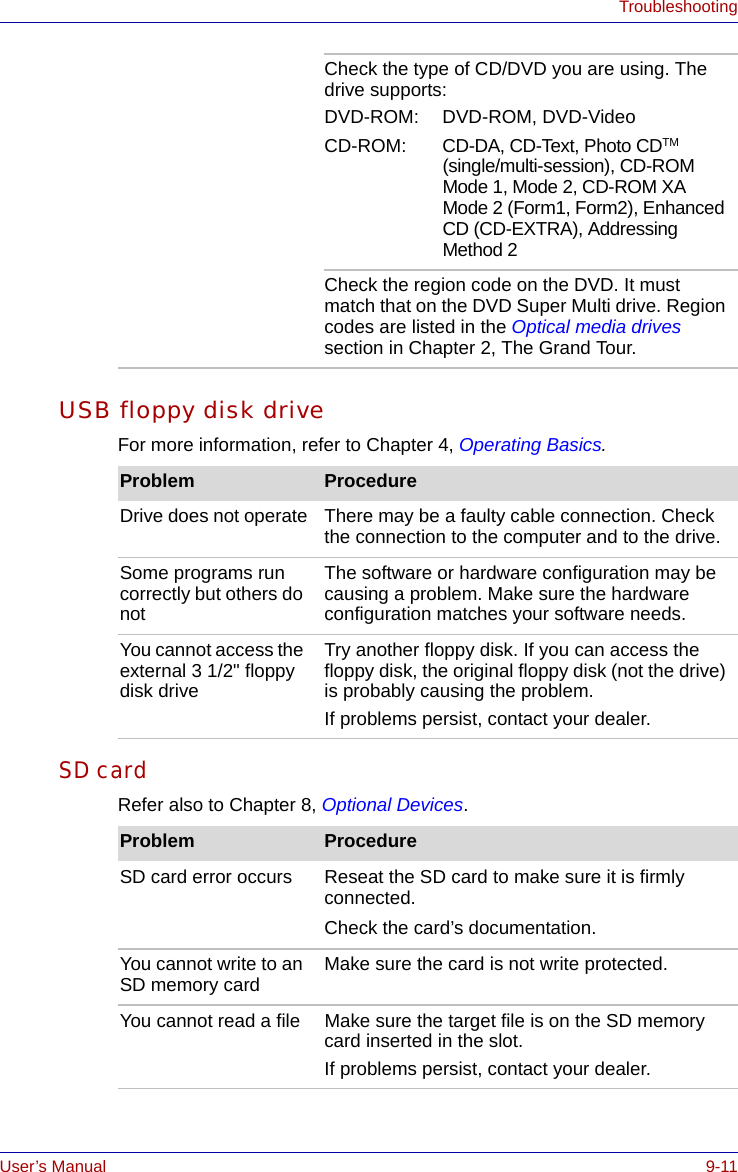
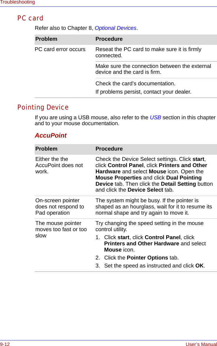
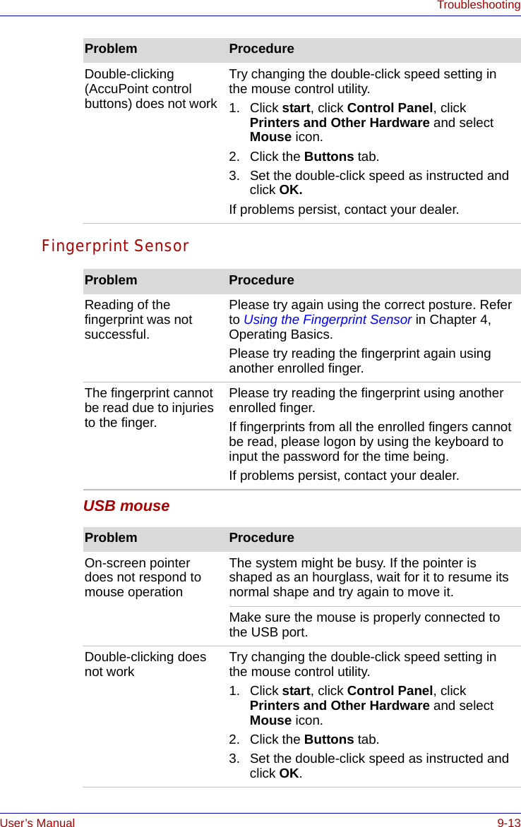
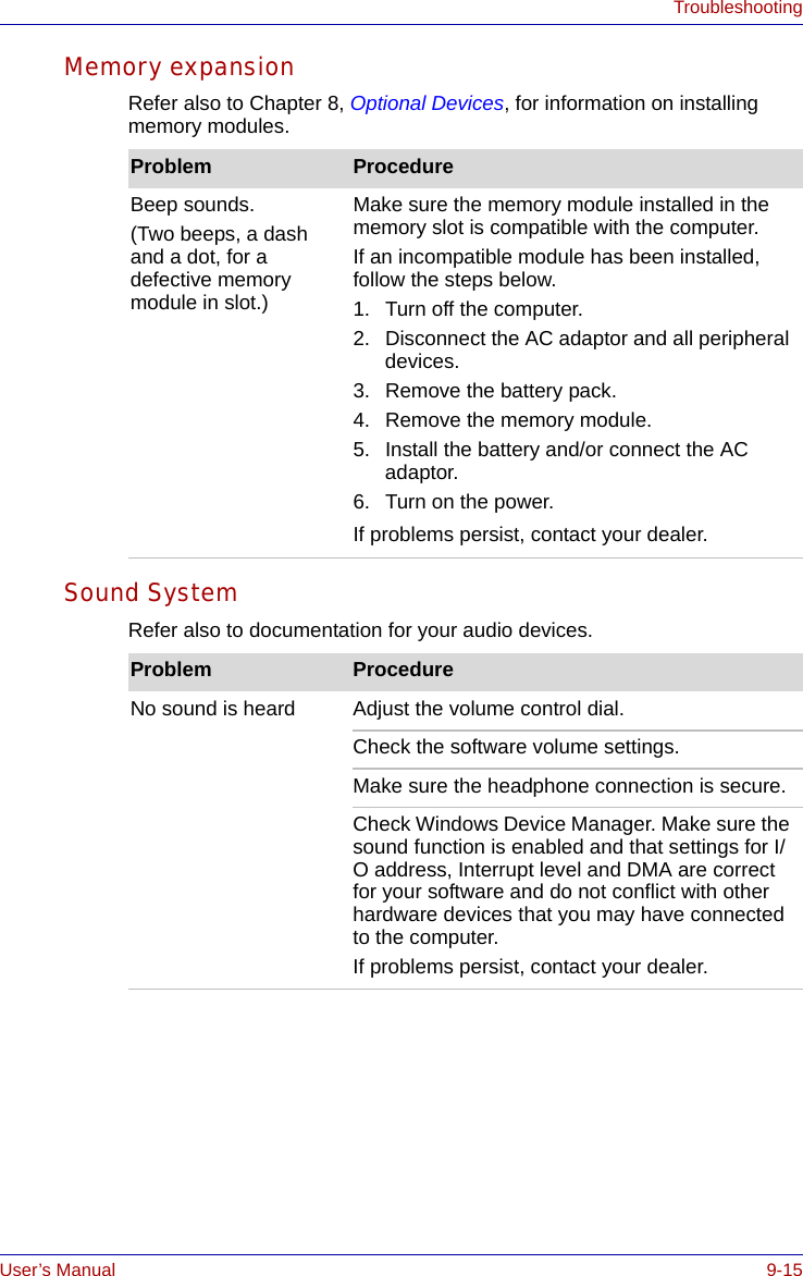
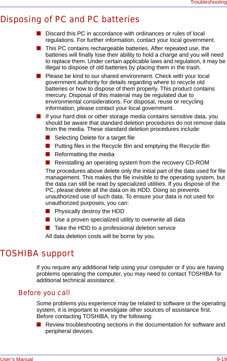
![User’s Manual 9-7TroubleshootingReal Time ClockPasswordKeyboard Keyboard problems can be caused by your setup configuration. For more information refer to Chapter 5, The Keyboard. Problem ProcedureThe following message is Displayed on the LCD screen:RTC battery is low or CMOS checksum is inconsistent. Press [F1] key to set Date/Time. The battery for RTC is wearing. Set the date and time in BIOS setup with the following steps:1. Press F1 key. BIOS setup will boot up.2. Set the date in System Date.3. Set the time in System Time.4. Press END key. Confirmation message will appear.5. Press Y key. BIOS setup will terminate and the computer will be rebooted.Problem ProcedureCannot enter password Refer to the TOSHIBA Password Utility section in Chapter 6, Power and Power-Up Modes.Problem ProcedureSome letter keys produce numbers Check that the numeric keypad overlay is not selected. Press FN + F11 and try typing again.Output to screen is garbled Make sure the software you are using is not remapping the keyboard. Remapping involves reassigning the meaning of each key. See your software’s documentation.If you are still unable to use the keyboard, consult your dealer.](https://usermanual.wiki/Dynabook/UPA3459WL.CRN-29045-Sub-notebook-User-manual-2-of-2/User-Guide-551599-Page-25.png)

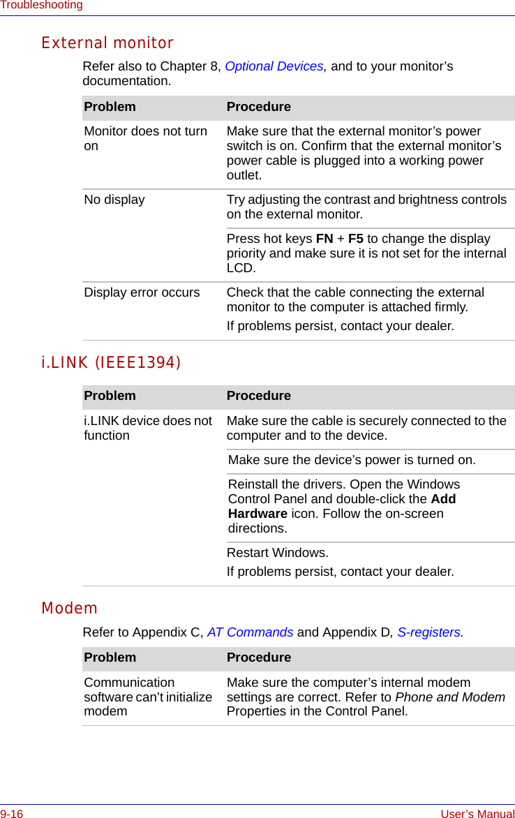
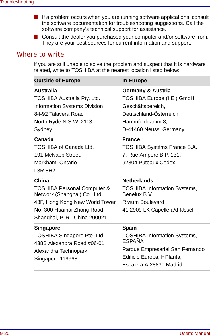

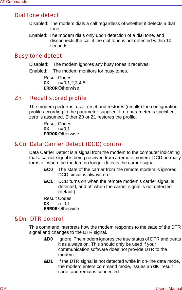
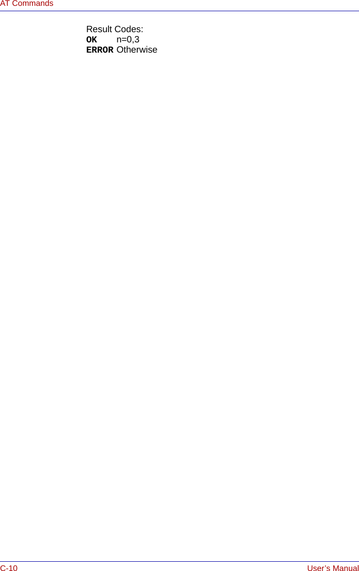
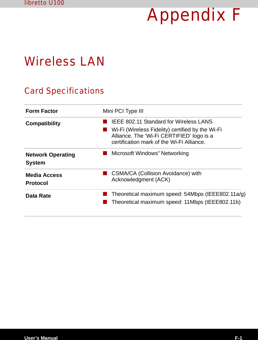
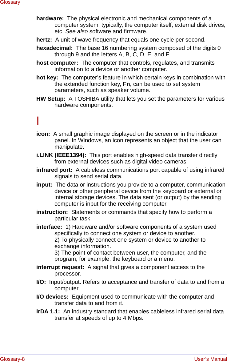
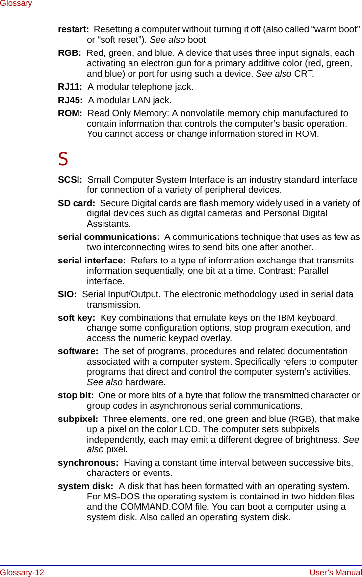
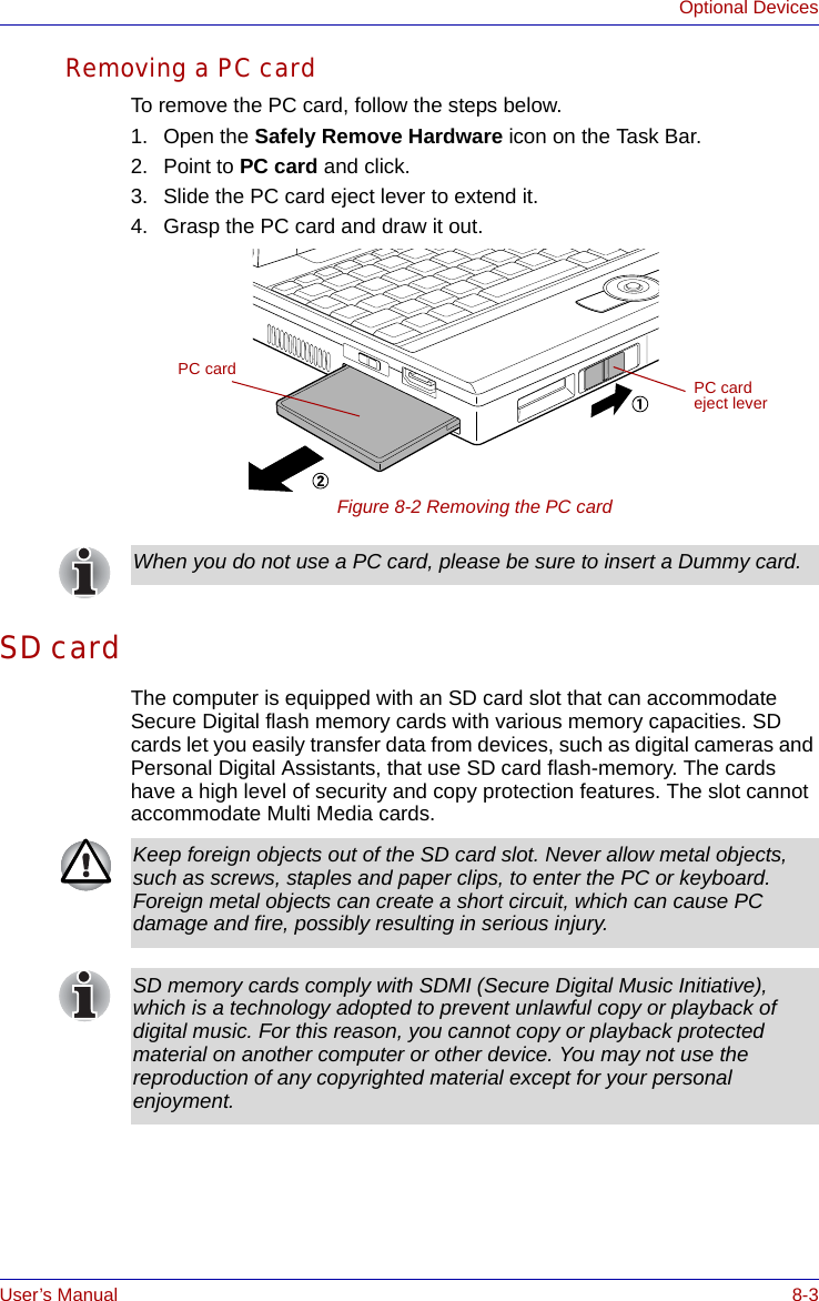
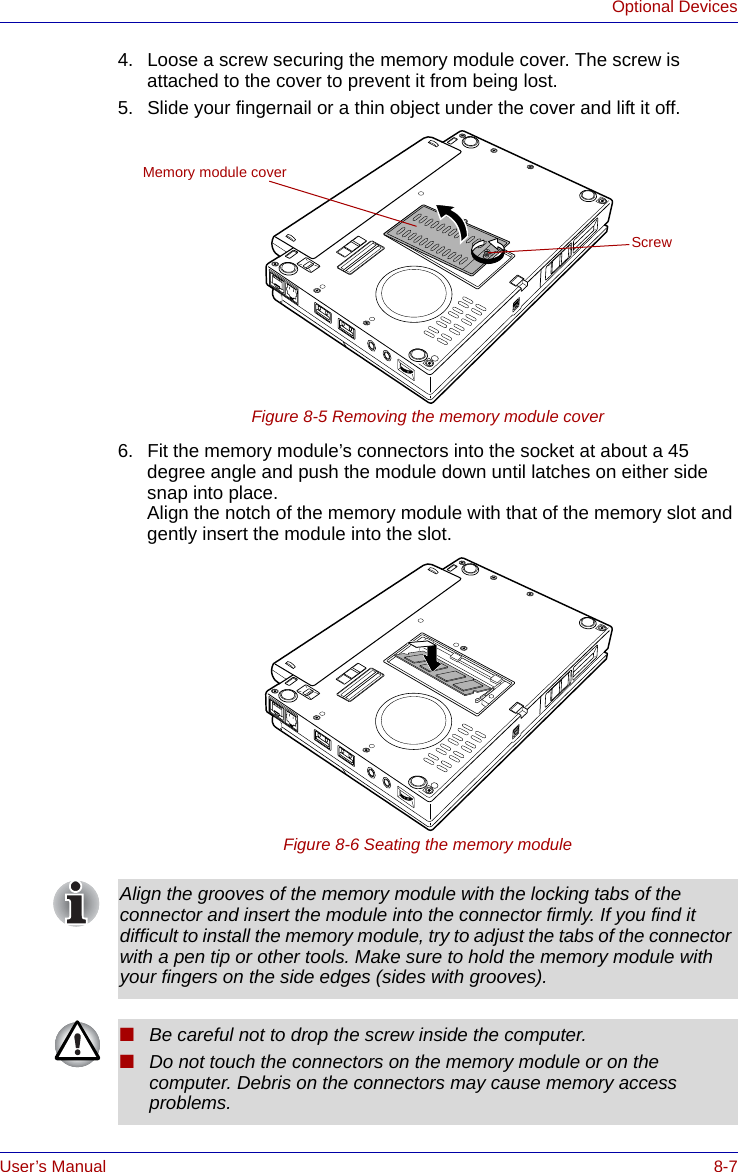
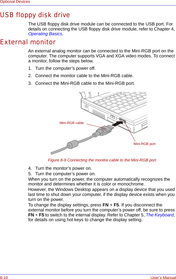
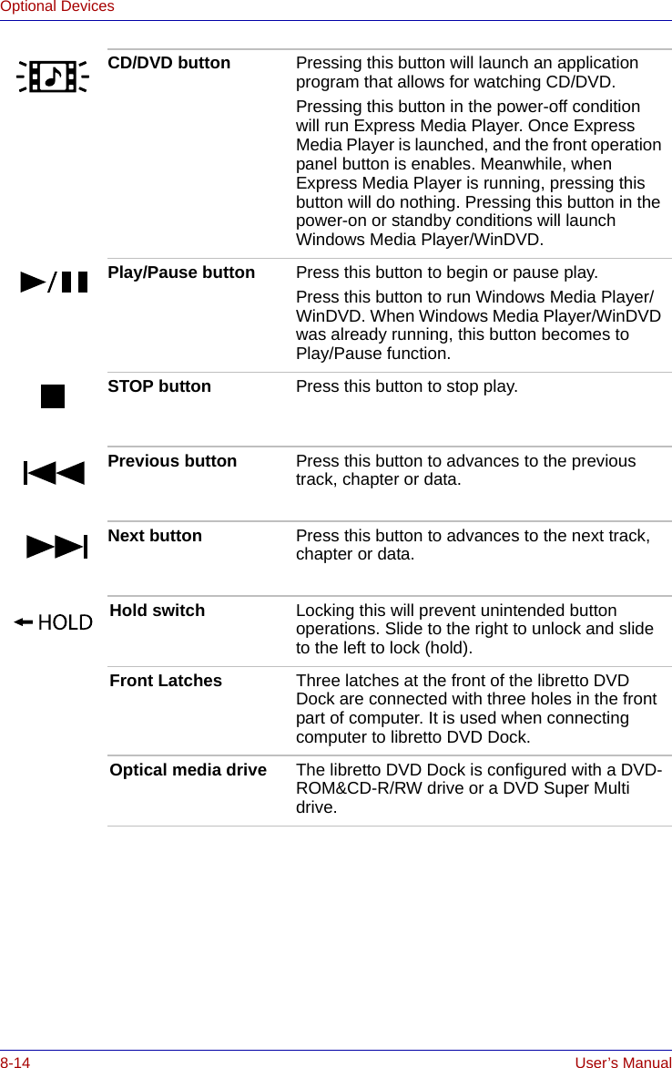
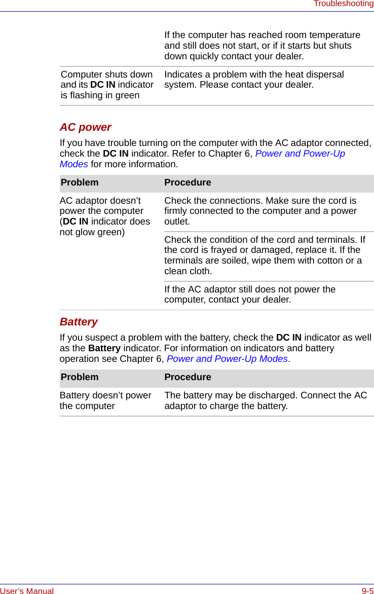
![User’s Manual 10-3DisclaimersWireless LAN/Atheros*6The transmission speed over the wireless LAN and the distance over which wireless LAN can reach may vary depending on surrounding electromagnetic environment, obstacles, access point design and configuration, and client design and software/hardware configurations.[54Mbps is the theoretical maximum speed under the IEEE802.11 (a/b/g) standard.] The actual transmission speed will be lower than the theoretical maximum speed.To use the Atheros Super AGTM or Super GTM function, your client and access point must support the corresponding feature. Performance of these functions may vary depending on the format of data transmitted.TV Tuner*7TV Tuner will function only in the country where the computer was purchased.Images*8All images are simulated for purposes of illustration.LCD Brightness and Eye Stain*9Your LCD display has a brightness approaching that of a TV device. We recommend that you adjust the brightness of your LCD to a comfortable level to prevent possible strain on your eyes.Safety Use for TV Tuner*10If you have to operate your PC during a thunderstorm and are connecting the TV tuner to an outside antenna, you should operate your PC using AC power mode. The AC adapter offers some protection against (but does not entirely prevent) possible electric shock caused by lightning. For complete protection, do not operate your PC during a thunderstorm.Graphics Processor Unit ("GPU”)*11Graphics processor unit ("GPU") performance may vary depending on product model, design configuration, applications, power management settings and features utilized. GPU performance is only optimized when operating in AC power mode and may decrease considerably when operating in battery power mode.](https://usermanual.wiki/Dynabook/UPA3459WL.CRN-29045-Sub-notebook-User-manual-2-of-2/User-Guide-551599-Page-43.png)


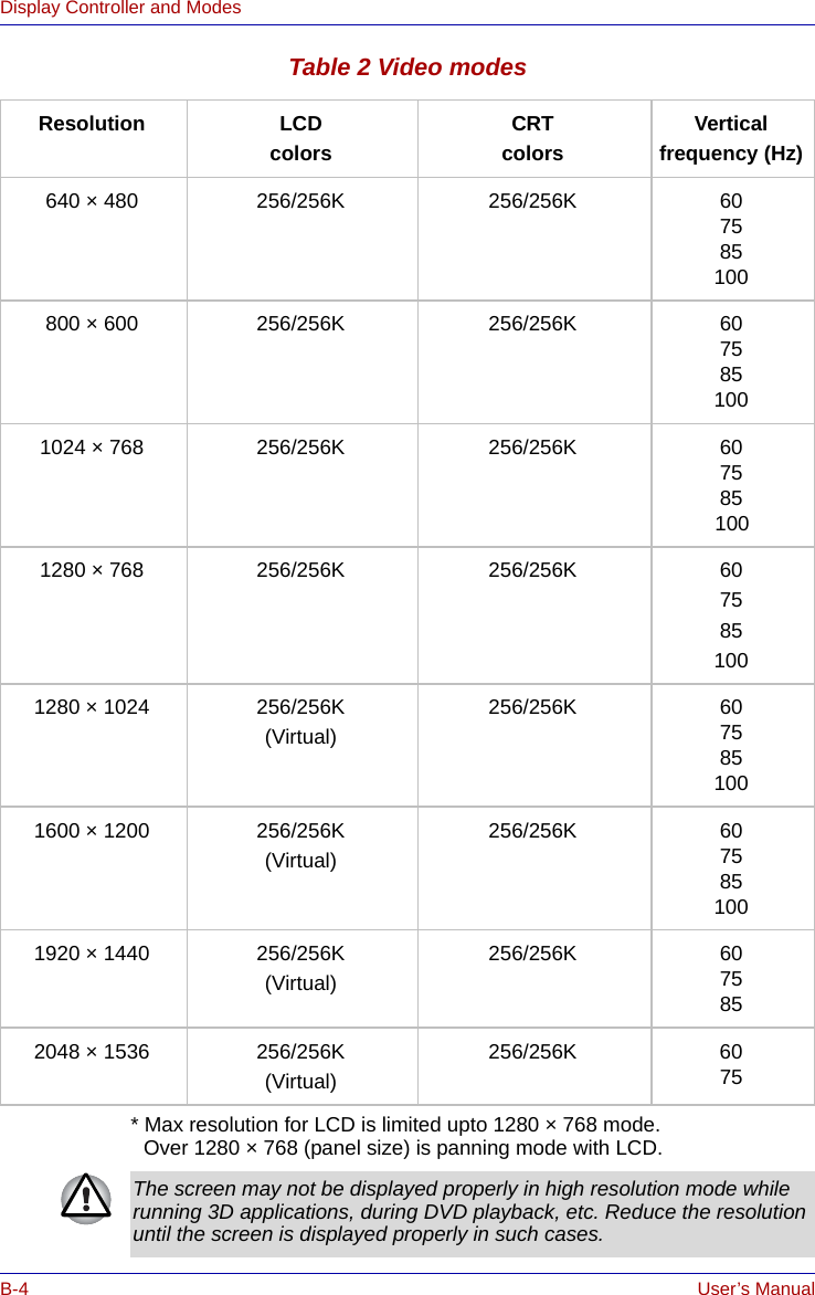
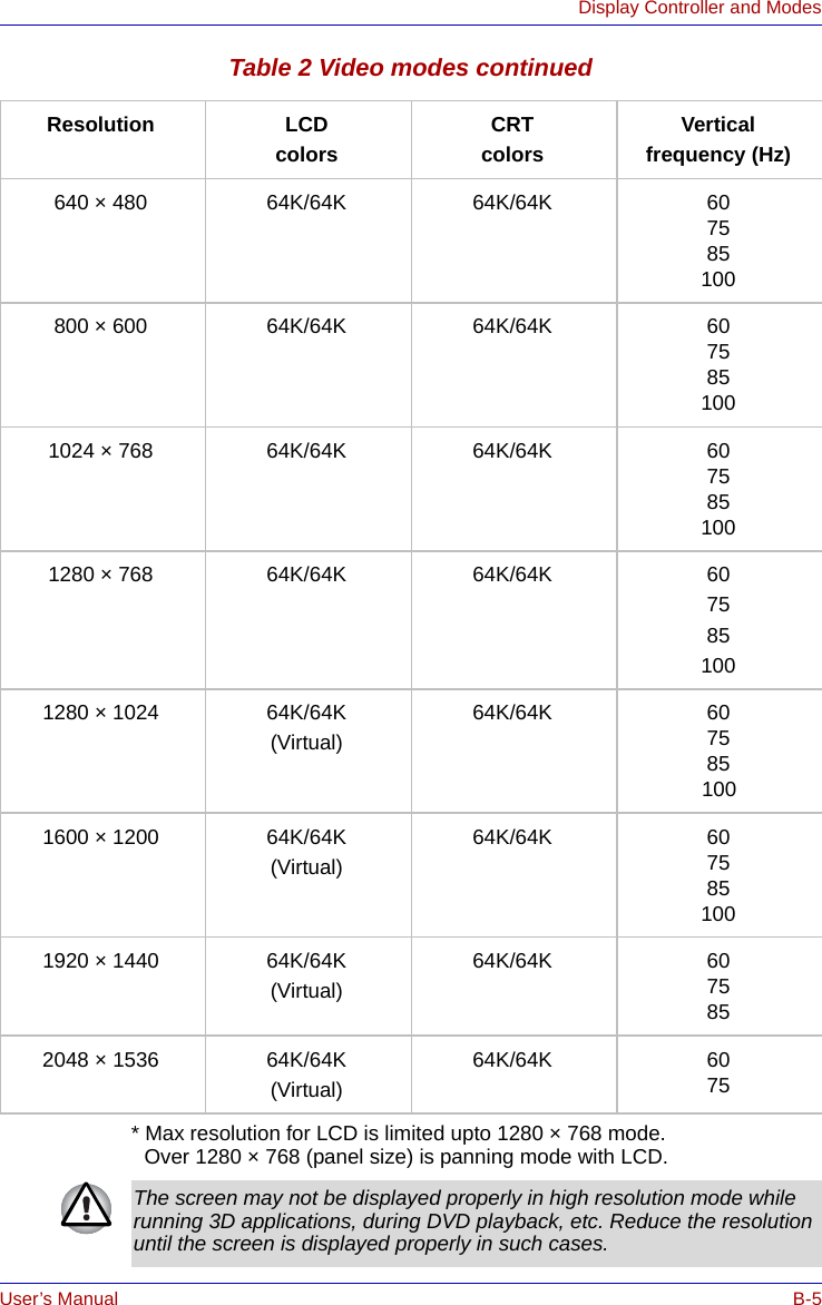
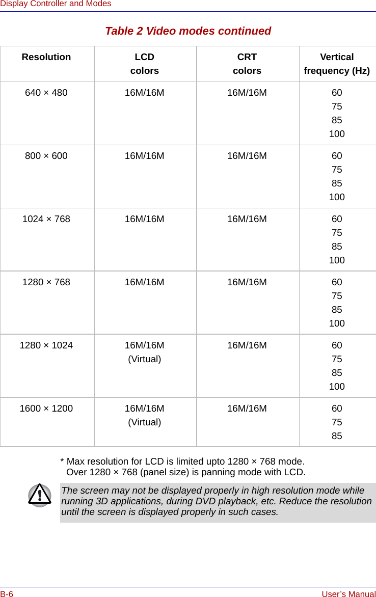
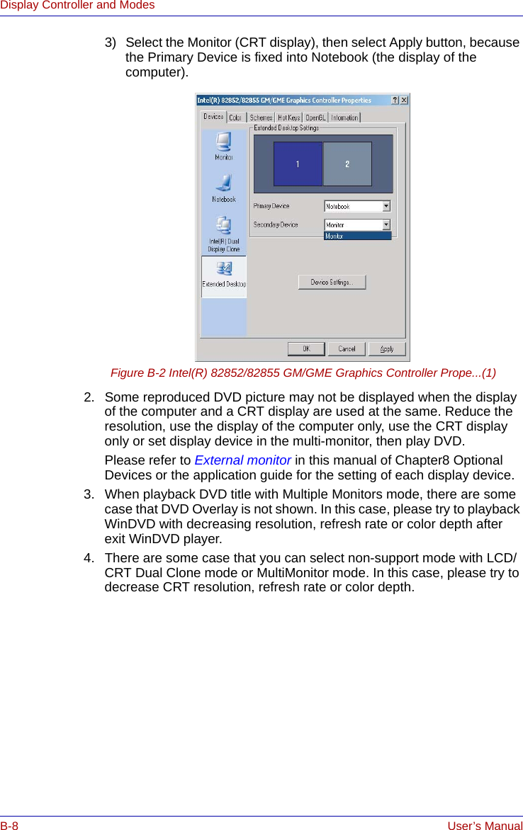
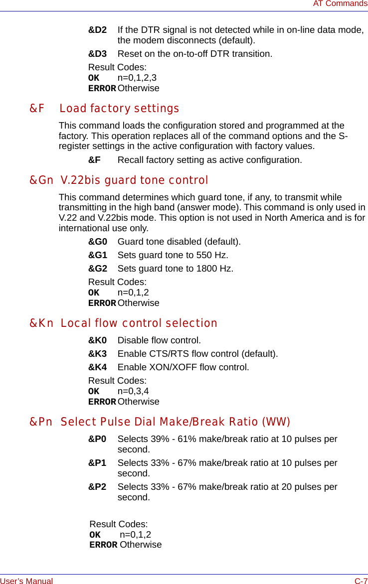
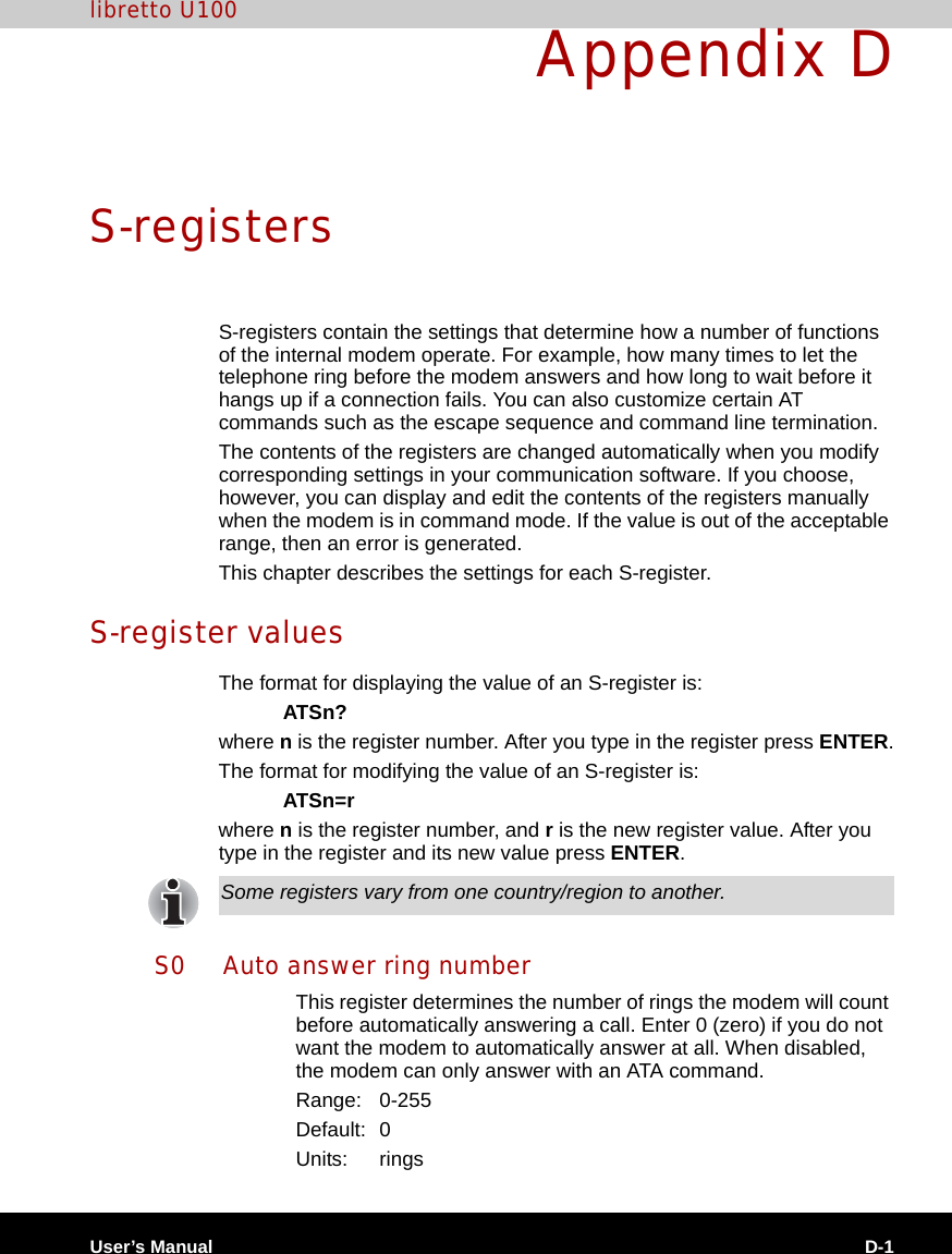
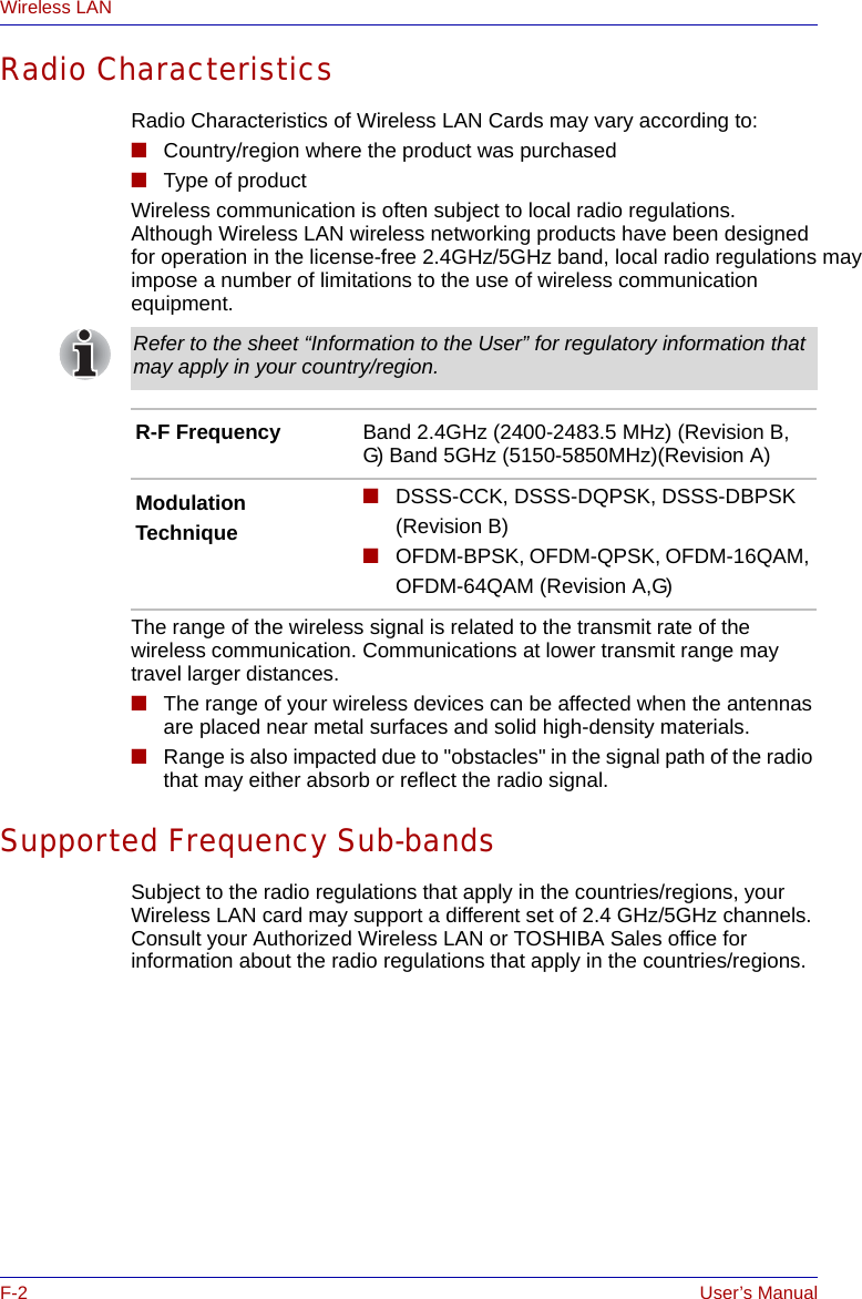
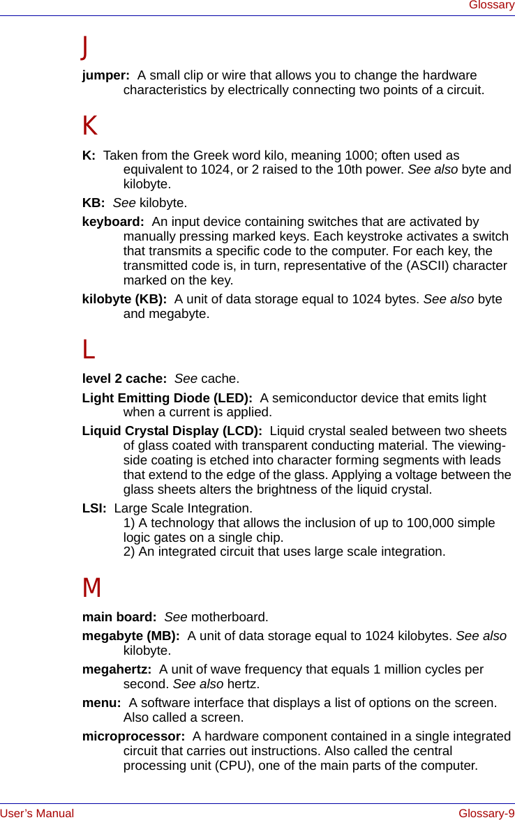
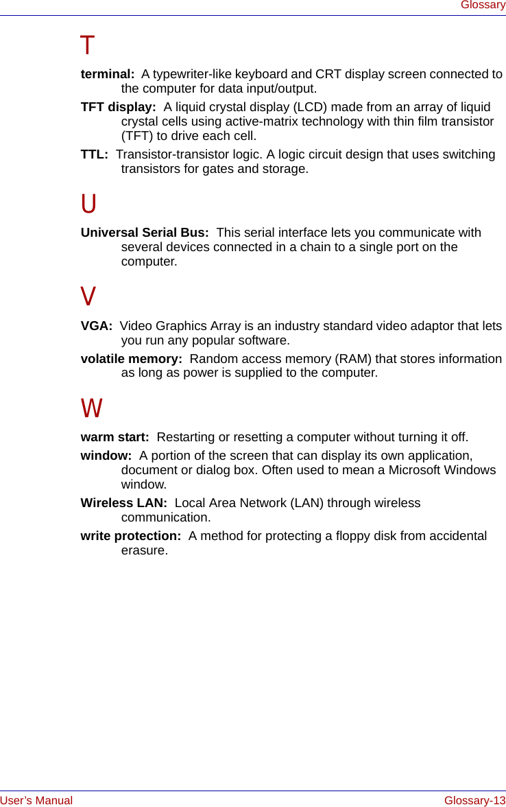
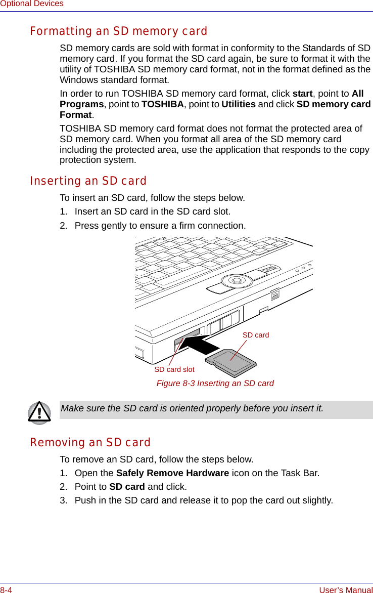
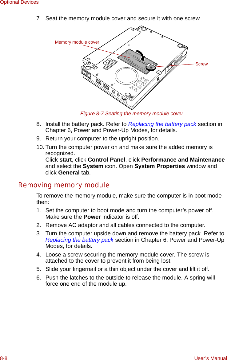
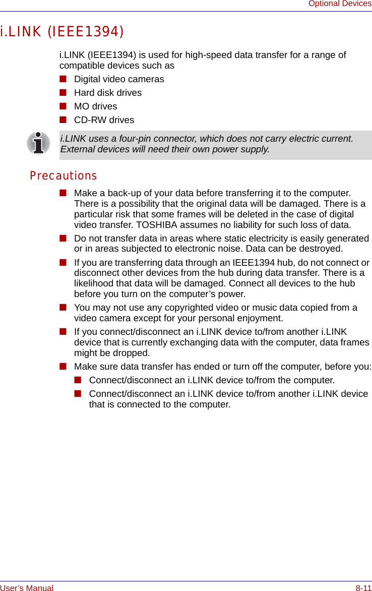
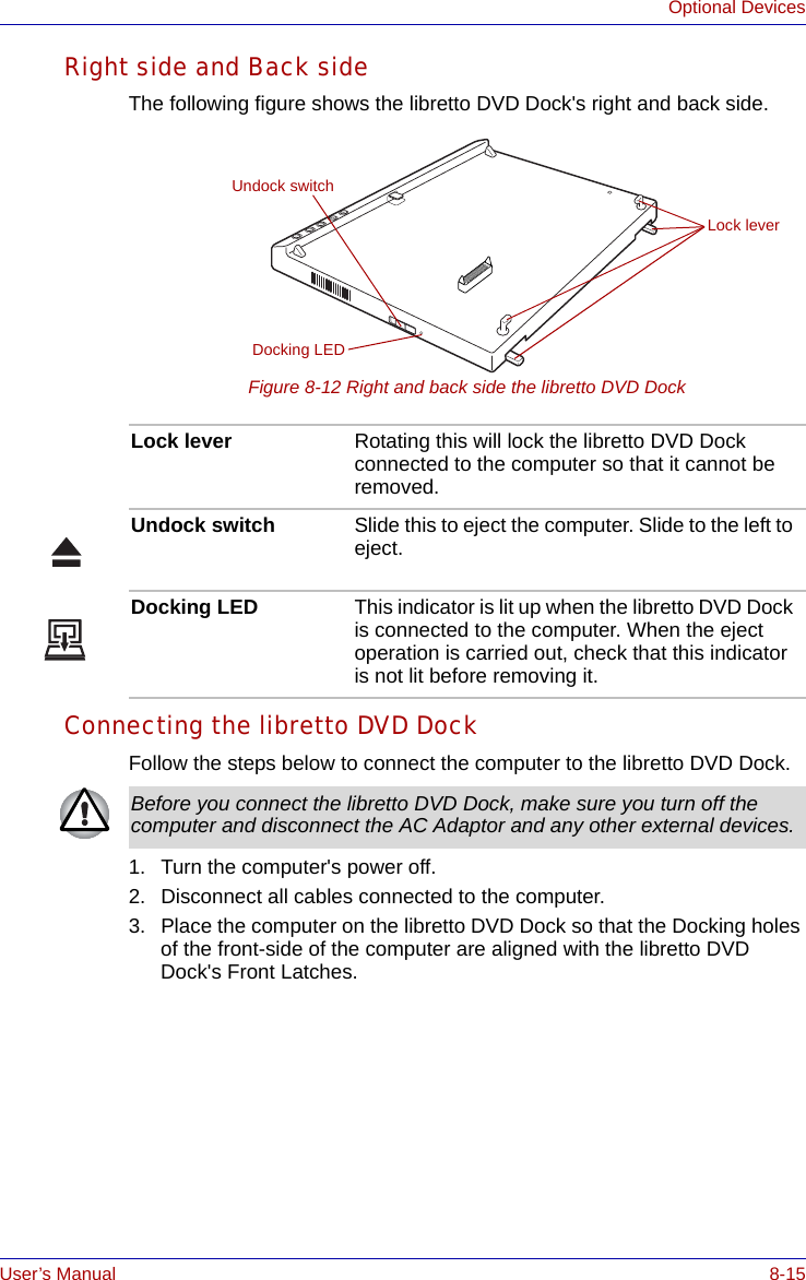
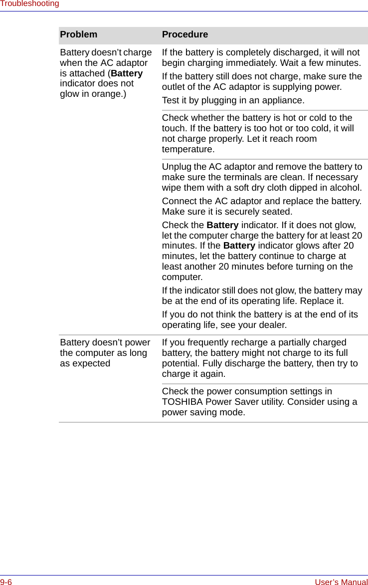
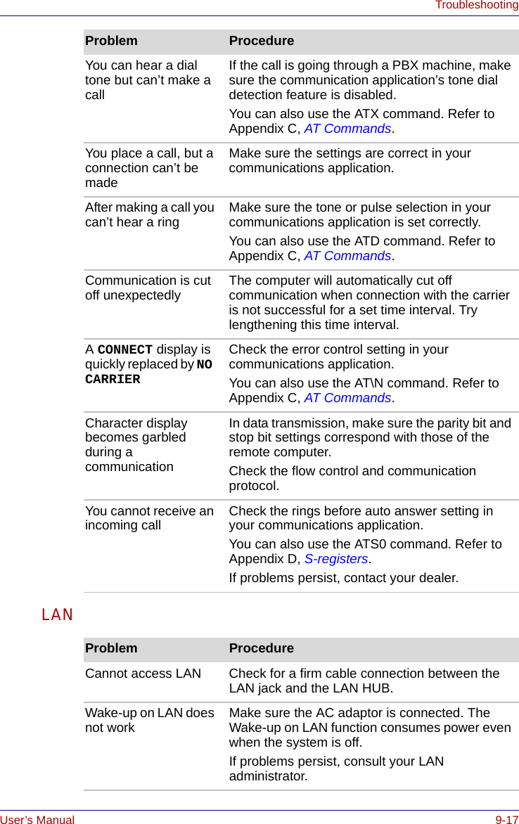
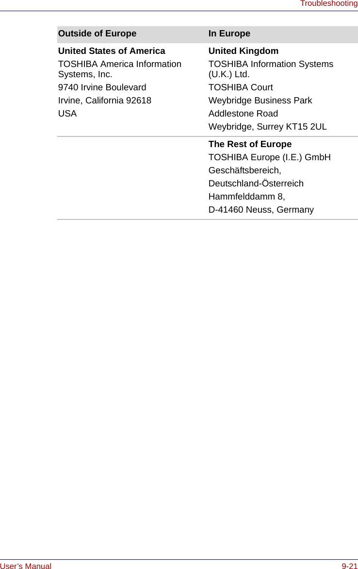
![User’s Manual B-7Display Controller and ModesDisplay settings1. You cannot move from the [Settings] tab of [Display Properties] to the multi-monitor when you are using the display of the computer and an external CRT display or a TV at the same time. *The [Settings] tab is displayed in the following steps;1) Open [Control Panel], click [Appearance and Themes].2) Click [display].3) Select [Settings] tab.Figure B-1 Display Properties (1)■The way to move to multi-monitor1) Press CTRL + ALT + F12 keys to make.[Intel(R) 82852/82855 GM/GME Graphics Controller Prope...] displayed (See Figure B-2).2) Click in the left of [Devices] tab (See Figure B-2), then select [Extended Desktop].](https://usermanual.wiki/Dynabook/UPA3459WL.CRN-29045-Sub-notebook-User-manual-2-of-2/User-Guide-551599-Page-55.png)