Dynabook UPA3459WL 802.11ag Half Size Mini-PCI WLAN Module User Manual CRN 29045 Sub notebook 1 of 2
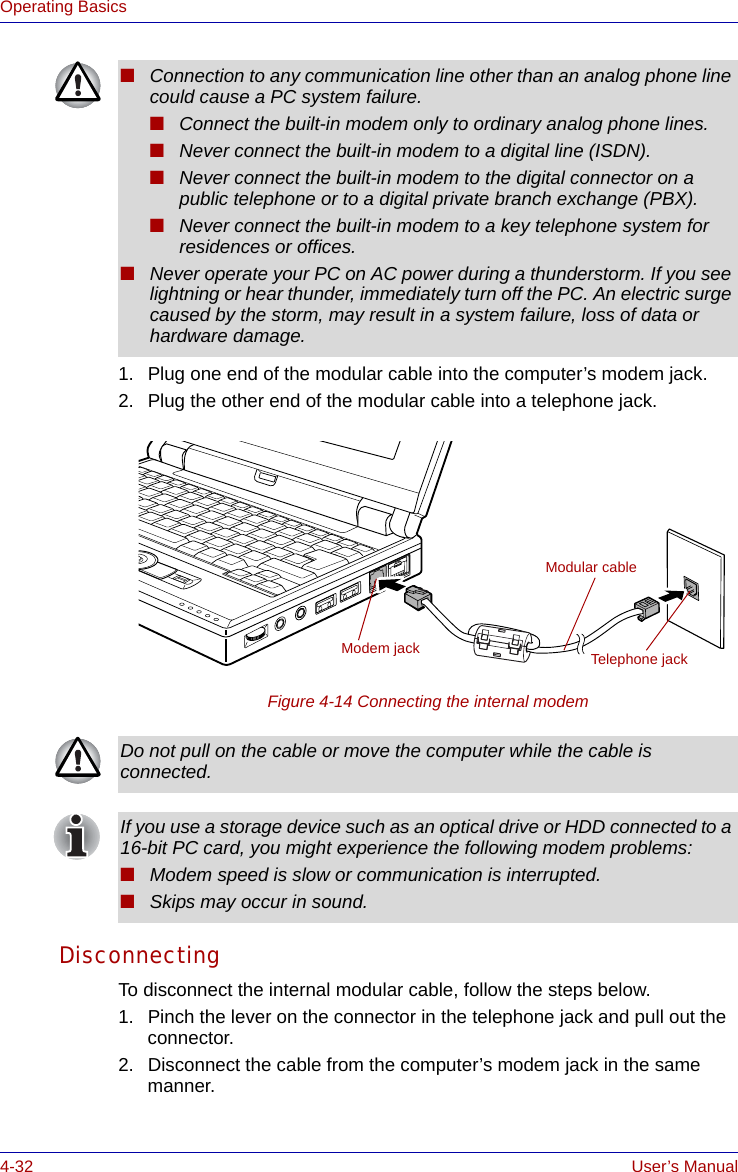
Toshiba Corporation 802.11ag Half Size Mini-PCI WLAN Module CRN 29045 Sub notebook 1 of 2
Dynabook >
Contents
CRN 29045 Sub notebook user manual 1 of 2
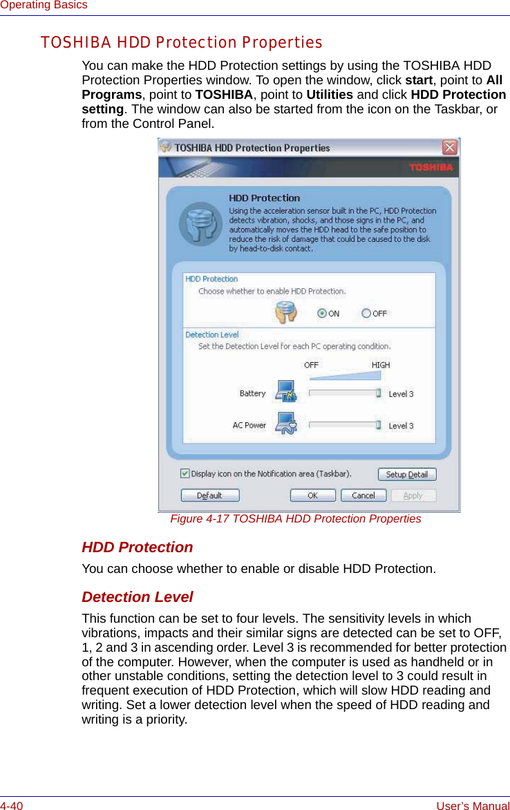
![iv User’s ManualUser’s ManualTelephone: (949) 583-3000EU Declaration of ConformityTOSHIBA declares, that the product: PLU10* conforms to the following Standards:This product is carrying the CE-Mark in accordance with the related European Directives. Responsible for CE-Marking is TOSHIBA Europe, Hammfelddamm 8, 41460 Neuss, Germany.VCCI Class B InformationModem warning noticeConformity StatementThe equipment has been approved to [Commission Decision “CTR21”] for pan-European single terminal connection to the Public Switched Telephone Network (PSTN).However, due to differences between the individual PSTNs provided in different countries/regions the approval does not, of itself, give an unconditional assurance of successful operation on every PSTN network termination point.In the event of problems, you should contact your equipment supplier in the first instance.Supplementary Information: “The product complies with the requirements of the Low Voltage Directive 73/23/EEC, the EMC Directive 89/336/EEC and/or the R&TTE Directive 1999/05/EEC.”](https://usermanual.wiki/Dynabook/UPA3459WL.CRN-29045-Sub-notebook-user-manual-1-of-2/User-Guide-551598-Page-4.png)


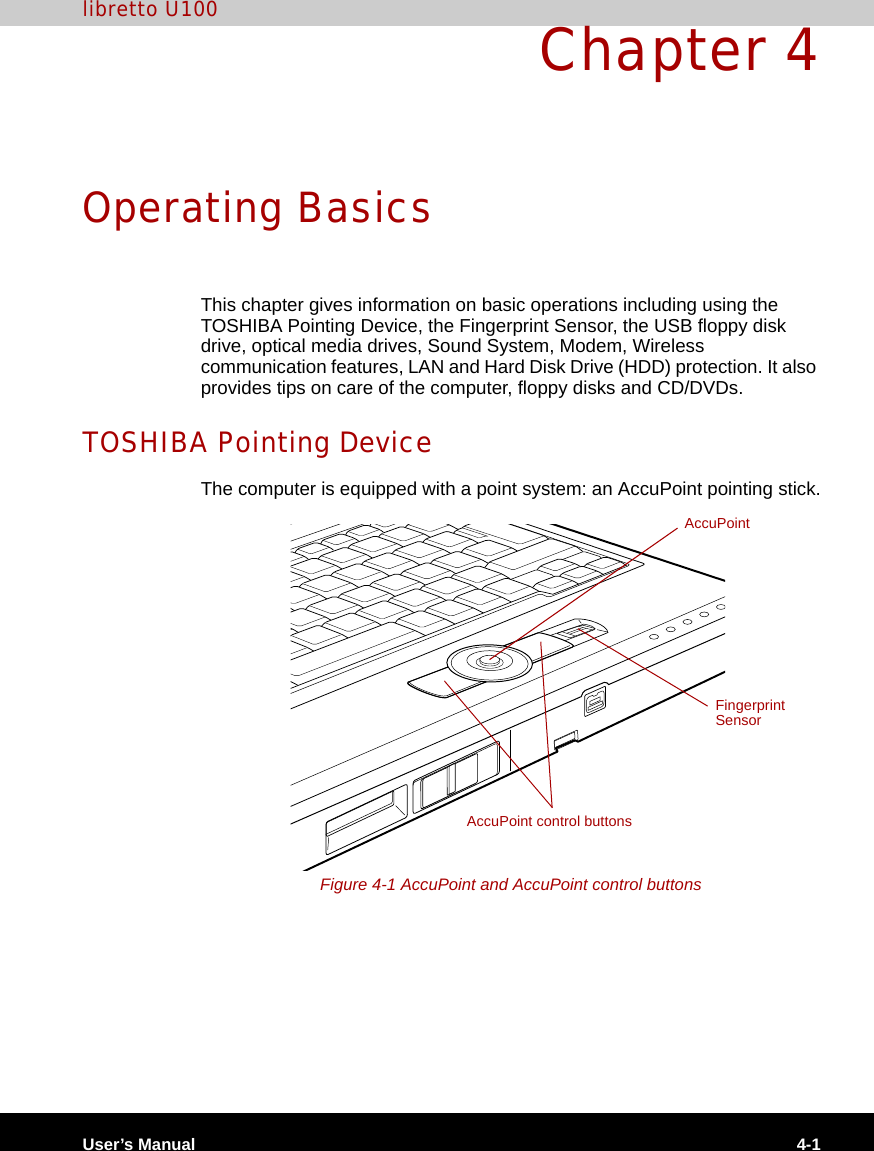
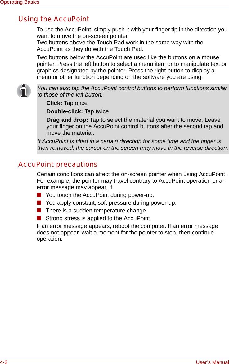
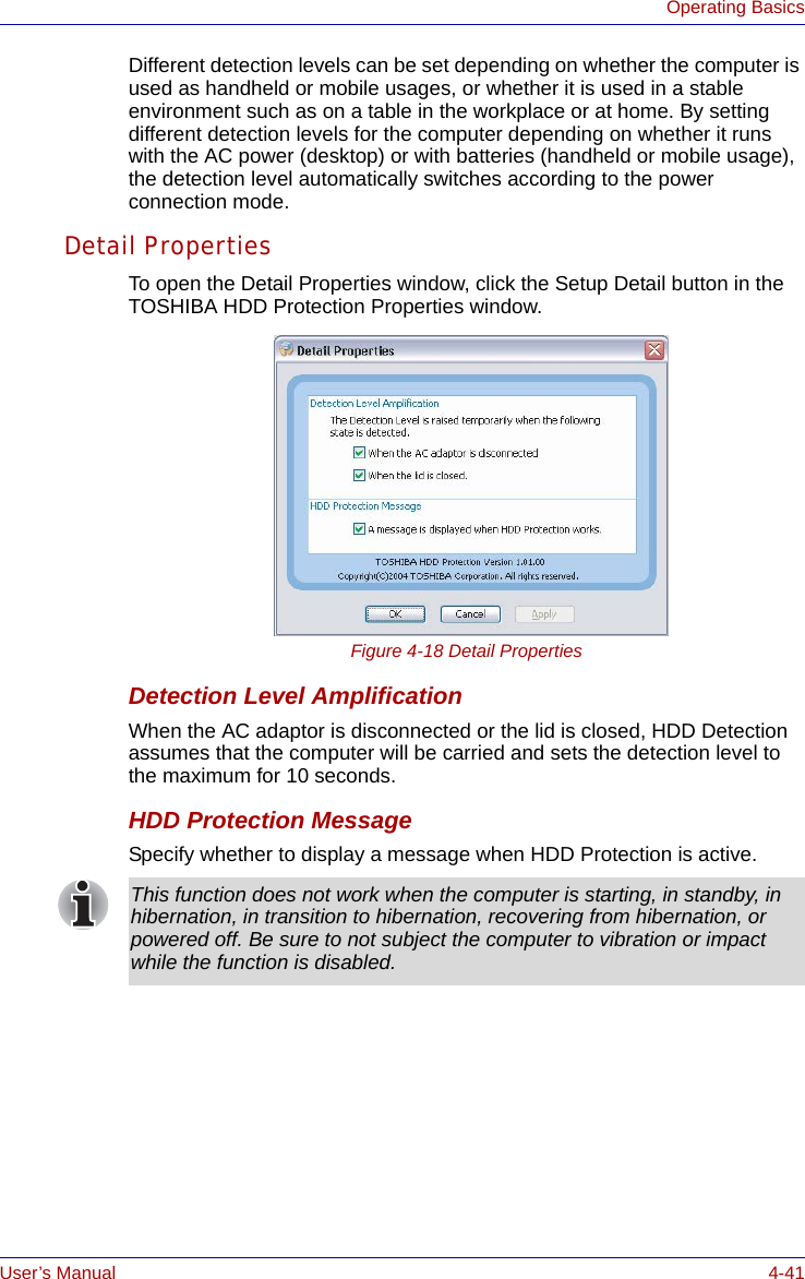
![1-16 User’s ManualIntroductionOptionsYou can add a number of options to make your computer even more powerful and convenient to use. The following options are available:TOSHIBA SD Memory Card Format This utility has the function which formats SD memory card by SD standard format.TOSHIBA Acoustic Silencer This utility has the function to set up the read speed of CD.It is ineffective in DVD.You can set up one of the modes: [Normal Mode] can read data early, and [Quiet Mode] can lessen noise.Memory expansion A 256, 512 or 1,024 MB memory module (DDR 333) can easily be installed in the computer.Battery pack An additional battery pack can be purchased from your TOSHIBA dealer. Use it as a spare or replacement.AC adaptor If you use your computer at more than one site frequently, it may be convenient to purchase an additional AC adaptor for each site so you will not have to carry the adaptor with you.USB floppy disk Kit USB floppy disk drive accommodates 1.44-megabyte or 720-kilobyte floppy disk. It connects to a USB port. (You cannot format 720-kilobyte floppy disks on Windows XP, but you can use previously formatted disks.)libretto DVD Dock A libretto DVD Dock accommodates one of the DVD-ROM& CD-R/RW or DVD Super Multi drives. It connects to a docking interface of the computer's underside.Bluetooth SD card3 Bluetooth SD card is an optional accessory compatible with the SD card slot of this computer. You can buy the card from TOSHIBA dealer.Bluetooth USB adaptor A Bluetooth adaptor that has a USB connector. Wireless communications can be carried out with Bluetooth-compatible equipment by connecting to the USB port of the computer.You can buy the module from TOSHIBA dealer.](https://usermanual.wiki/Dynabook/UPA3459WL.CRN-29045-Sub-notebook-user-manual-1-of-2/User-Guide-551598-Page-46.png)

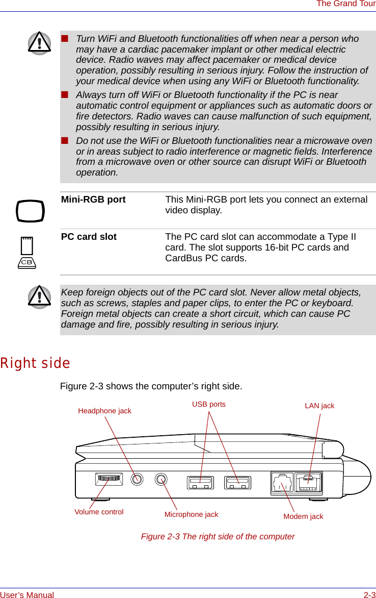
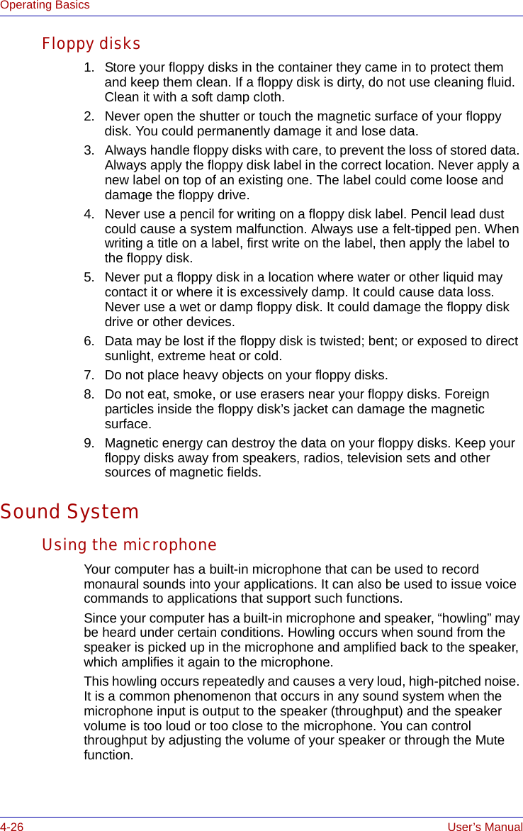
![User’s Manual 4-23Operating Basics4. Click the Advanced tab in the System Properties window.5. Click the Settings icon in the "Performance" section.6. Click the Advanced tab in the Performance Options window.7. Click the Change icon in the "virtual memory" section.8. Select the Custom size button in the Virtual Memory window.9. Specify much higher values for "Initial size" and "Maximum size." 10. Click the Set button in the Virtual Memory window.11. Click the OK button in the Virtual Memory window.How to make a DVD-VideoSimplified steps for making a DVD-Video from video data captured from a DV-Camcorder:1. Click [Start]-[All Programs] - [InterVideo WinDVD Creator2] - [InterVideo WinDVD Creator] to launch WinDVD Creator.2. Click [Capture] button then capture the video data from the DV-Camcorder via IEEE1394.3. Click [Edit] button then drag the video clips from [Video Library] tab to the edit track.4. Click [Make Movie] button in the top bar.5. Double Click the Right arrow button icon in the center of right side.6. Put a blank DVD-R/+R disc or an erased DVD-RW/+RW disc in the drive.7. Click [Start] to record to the disc.8. When recording is finished, the tray opens.How to learn more about InterVideo WinDVD CreatorPlease refer to the on-line Help for additional InterVideo WinDVD Creator information.Important information for useNote the following limitations when you write video DVD:1. Editing digital video■Log in with Administrator rights to use WinDVD Creator.■Make sure that your computer is running on AC power when using WinDVD Creator.■Operate the computer at Full Power. Do not use power-saving features.■While you are editing DVD, you can display previews. However, if another application is running, the preview might not display properly.■WinDVD Creator cannot show video on the external monitor when in simultaneous mode.■WinDVD Creator cannot edit or play copy protected content.](https://usermanual.wiki/Dynabook/UPA3459WL.CRN-29045-Sub-notebook-user-manual-1-of-2/User-Guide-551598-Page-101.png)
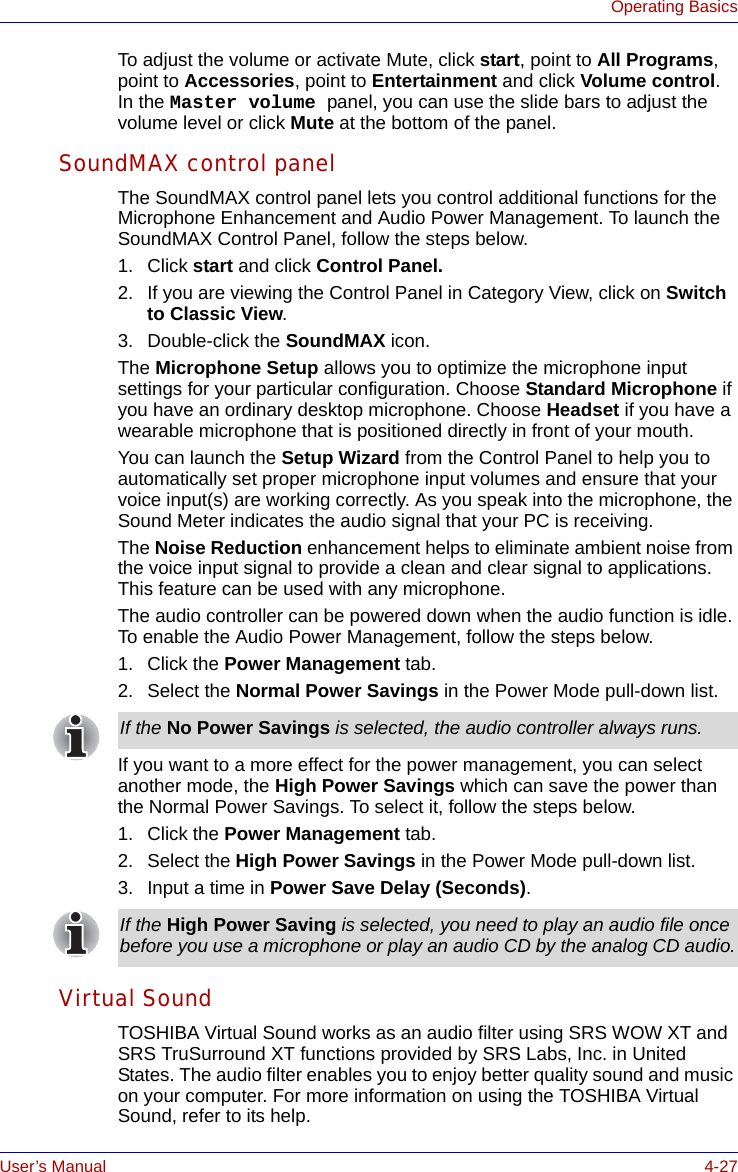
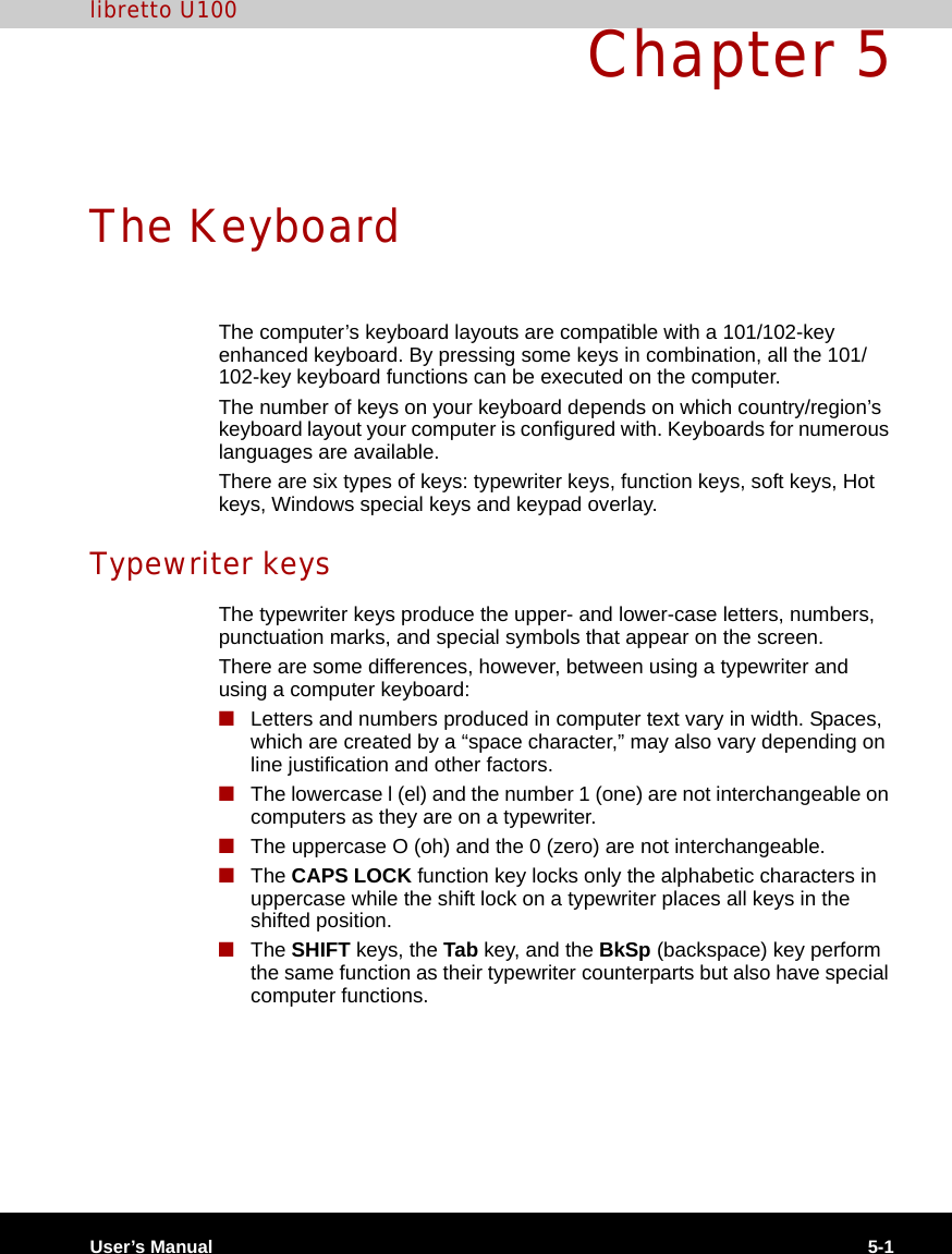
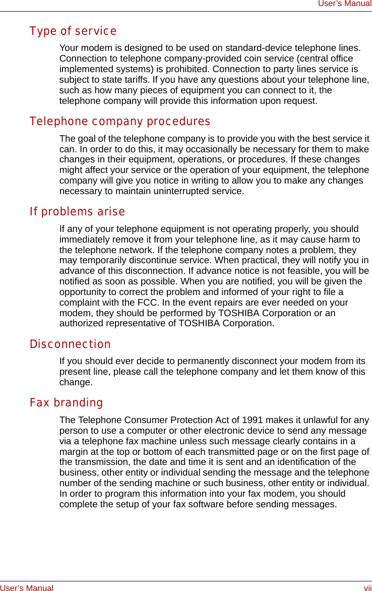
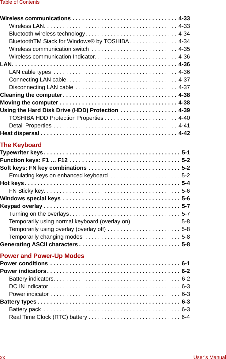
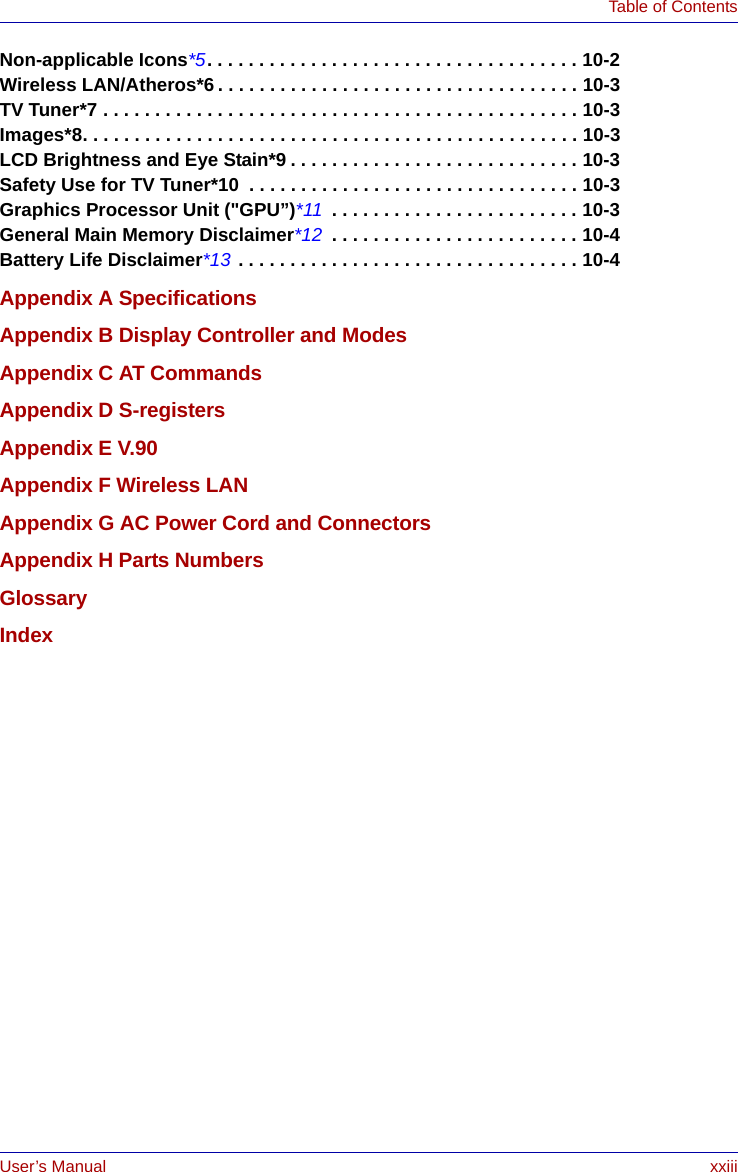
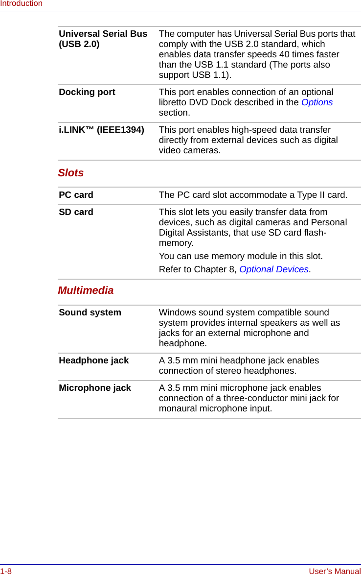
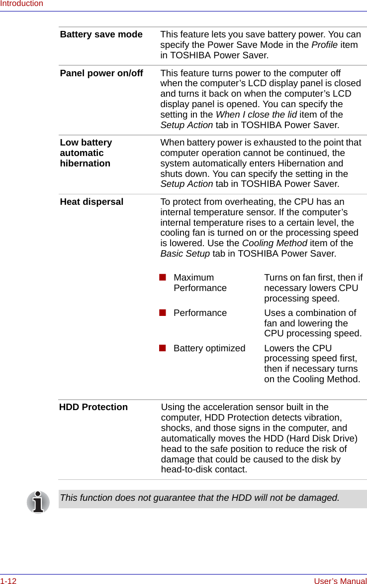
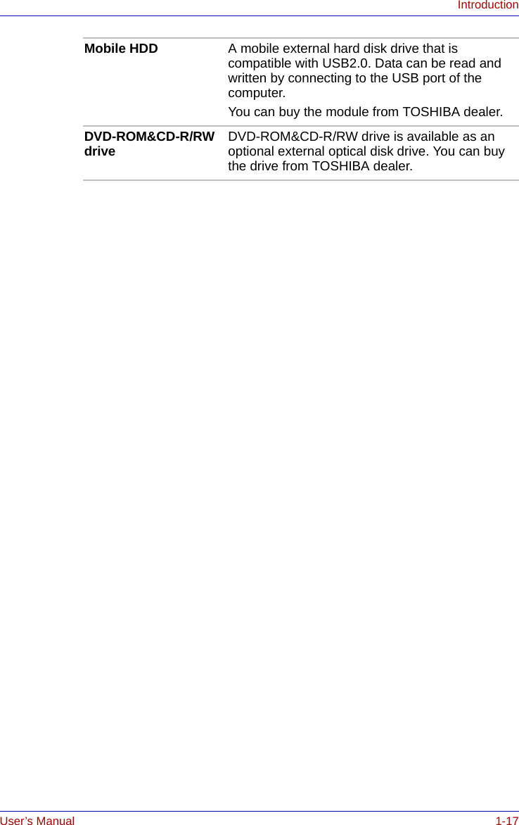
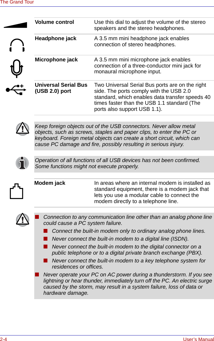
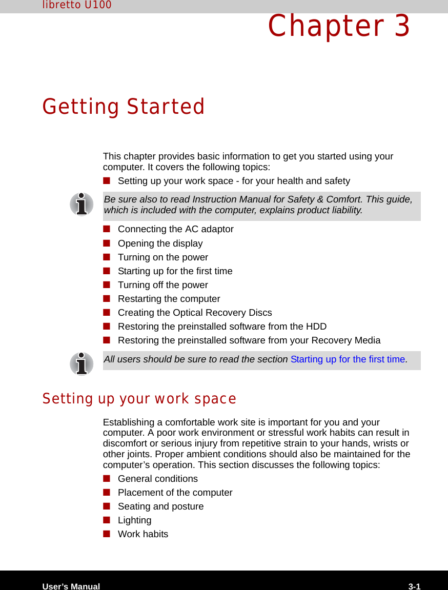
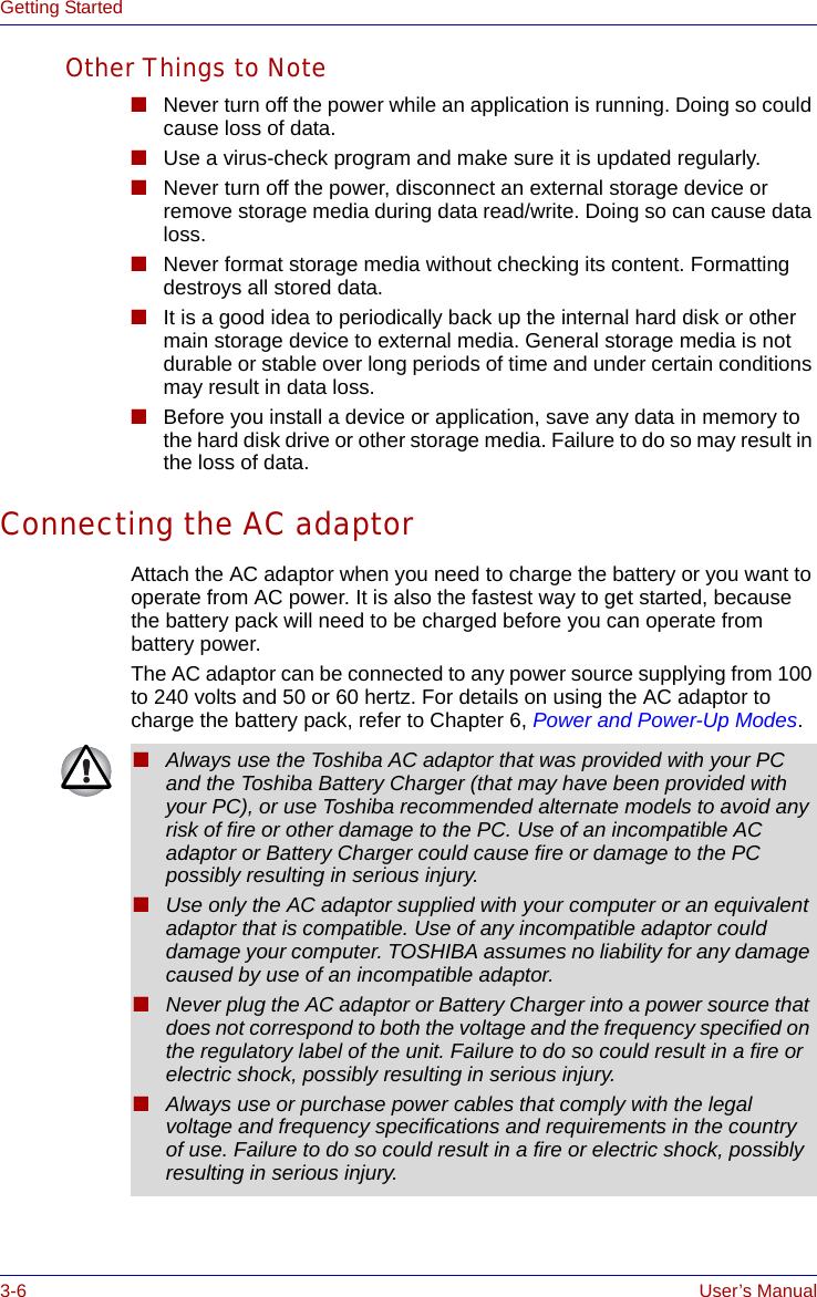
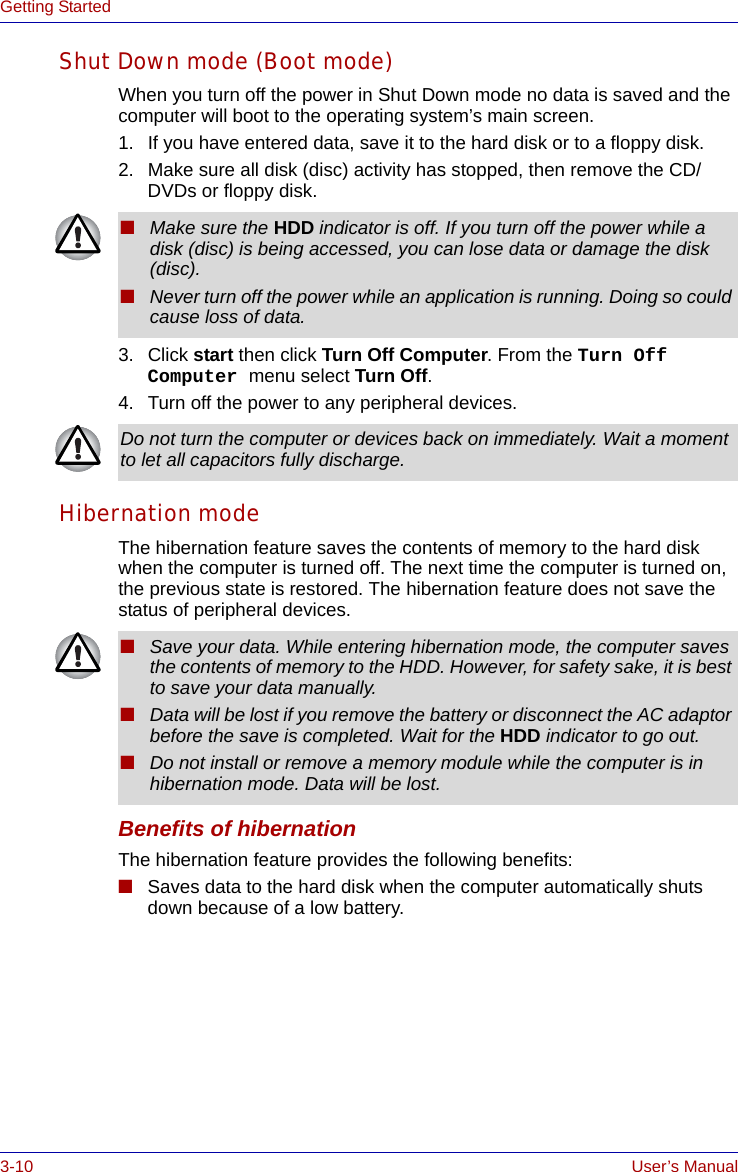
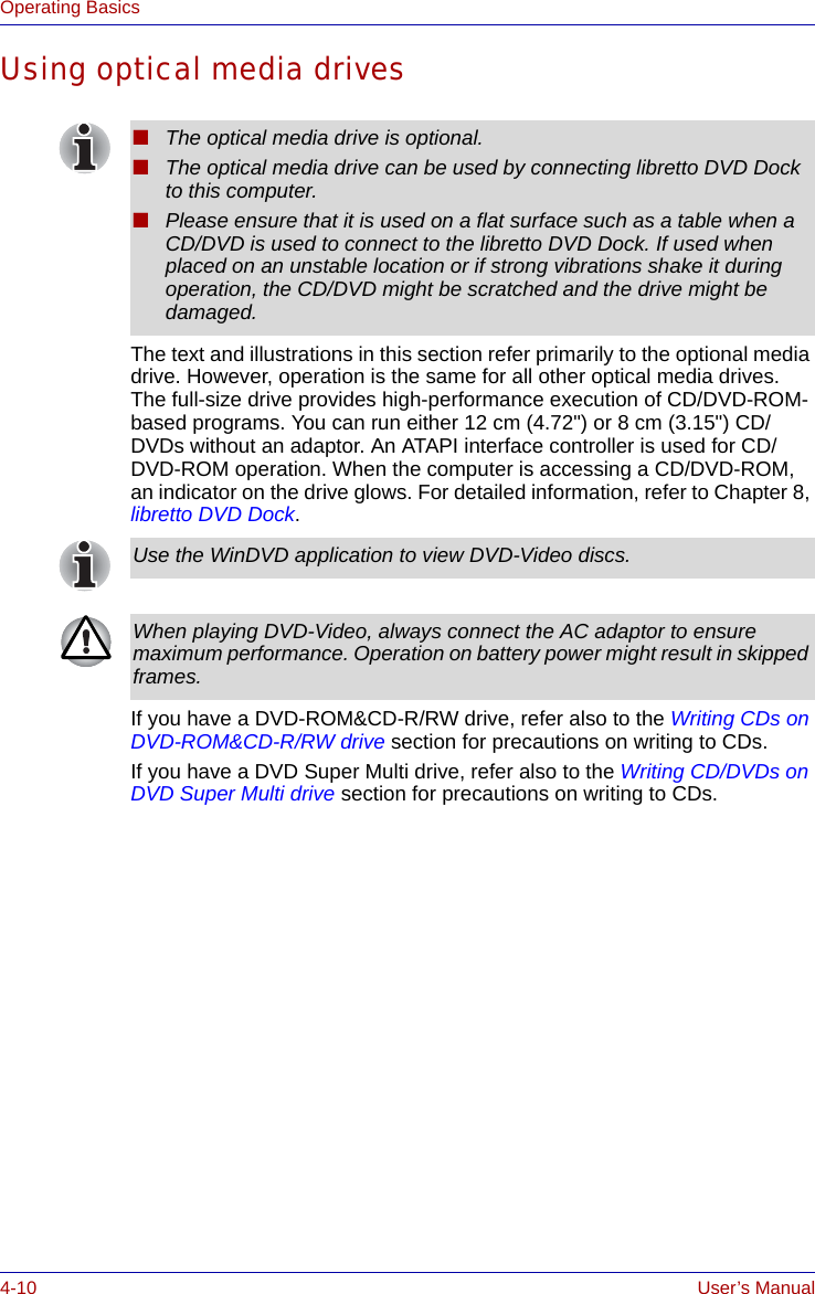
![5-2 User’s ManualThe KeyboardFunction keys: F1 … F12The function keys (not to be confused with FN) are the 12 keys at the top of your keyboard. These keys function differently from other keys.F1 through F12 are called function keys because they execute programmed functions when pressed. Used in combination with the FN key, keys marked with icons execute specific functions on the computer. Refer to the section, Soft keys: FN key combinations, in this chapter. The function executed by individual keys depends on the software you are using. Soft keys: FN key combinationsThe FN (function) is unique to TOSHIBA computers and is used in combination with other keys to form soft keys. Soft keys are key combinations that enable, disable or configure specific features.Emulating keys on enhanced keyboardFigure 5-1 A 101-key enhanced keyboard layoutThe keyboard is designed to provide all the features of the 101-key enhanced keyboard, shown in figure 5-1. The 101/102-key enhanced keyboard has a numeric keypad and scroll lock key. It also has additional Enter and Ctrl keys to the right of the main keyboard. Since the keyboard is smaller and has fewer keys, some of the enhanced keyboard functions must be simulated using two keys instead of one on the larger keyboard.Your software may require you to use keys that the keyboard does not have. Pressing the FN key and one of the following keys simulates the enhanced keyboard’s functions.Some software may disable or interfere with soft-key operations. Soft-key settings are not restored by the Standby feature.Esc#3Home PgUpBk SpF1 F2 F3 F4 F5 F6 F7 F8 F9 F10 F11 F12 ! 12$4%568 (9 )0&7_+=PgDnEndShiftDelInsCapsLockShiftEnterQW RTY U I O P {[}]E~`ASDFGHJ KL:;@?/> .< ,MNVCXZB\^*+-TabAltAltEnter 7Home8 9PgUp654 1End2 3PgDn 0InsNumLock .Del PrtScScroll lockPauseBreakCtrlCtrlSysReq/*.,,,](https://usermanual.wiki/Dynabook/UPA3459WL.CRN-29045-Sub-notebook-user-manual-1-of-2/User-Guide-551598-Page-122.png)
![6-4 User’s ManualPower and Power-Up ModesTo ensure that the battery pack maintains its maximum capacity, operate the computer on battery power at least once a month until the battery pack is fully discharged. Refer to Extending battery life in this chapter for procedures. If the computer is continuously operated on AC power through an AC adaptor for an extended period, more than a month, the battery may fail to retain a charge. It may not function efficiently over the expected life of the battery and the Battery indicator may not indicate a low-battery condition.Real Time Clock (RTC) batteryThe Real Time Clock (RTC) battery provides power for the internal real time clock and calendar. It also maintains the system configuration.If the RTC battery becomes completely discharged, the system loses this data and the real time clock and calendar stop working. The following message appears when you turn on the power:S**** RTC battery is low or CMOS checksum is inconsistent **** Press [F1] key to set Date/Time. You can change the setting of RTC by pressing F1 key. Refer to Chapter 9 Troubleshooting for the detail.■The battery pack is a lithium ion battery, which can explode if not properly replaced, used, handled or disposed of. Dispose of the battery as required by local ordinances or regulations. Use only batteries recommended by TOSHIBA as replacements.■Always dispose of used battery packs in compliance with all applicable laws and regulations. Put insulating tape, such as cellophane tape, on the electrode during transportation to avoid a possible short circuit, fire or electric shock. Failure to do so could possibly result in serious injury.■Do not remove the battery pack while the computer is in Standby mode. Data is stored in RAM, so if the computer loses power it will be lost. When the computer is powered off in Standby mode, and the AC adaptor is not connected, the battery pack supply power to maintain data and program in memory. If the battery pack is completely discharged, Standby mode does not function and the computer loses all data in memory.The computer’s RTC battery is a lithium ion battery and should be replaced only by your dealer or by a TOSHIBA service representative. The battery can explode if not properly replaced, used, handled or disposed of. Dispose of the battery as required by local ordinances or regulations.](https://usermanual.wiki/Dynabook/UPA3459WL.CRN-29045-Sub-notebook-user-manual-1-of-2/User-Guide-551598-Page-132.png)


![7-4 User’s ManualHW Setup3. Use the left/right cursor keys to highlight the boot device you want and press ENTER.Network Boot ProtocolThis feature sets the protocol to remotely boot from the network. [PXE] Sets PXE as the protocol (Default).[RPL] Sets RPL as the protocol.HDD Priority OptionsSet the priority of the HDD as a startup device.USB Memory BIOS Support TypeSet the type of the USB memory as a startup device.■If a supervisor password is set only, it is the following.■The menu above appears (able to run HW Setup).■The menu above does not appear (unable to run HW Setup).■If the supervisor and user password are set, it is the following.■The menu above appears when you use the supervisor and user password to start the computer (able to run HW Setup).■The menu above does not appear when you use the user password to start the computer (unable to run HW Setup).■The menu above appears when you use the supervisor password to start the computer (unable to run HW Setup).■The selection method above does not change the boot priority settings in HW Setup.■If you press a key other than one of those above or if the selected device is not installed, the system will boot according to the current setting in HW Setup.Built-in HDD -> USB The priority is set as built-in HDD -> USB memory (Default).USB -> Built-in HDD The priority is set as USB memory -> built-in HDD.HDD Set the type of the USB memory to be equivalent to the HDD (Default).* Based on the [HDD] order in the [Boot Priority Options] item. The order with respect to the other HDD can be set in the [HDD Priority Options] item.FDD Set the type of the USB memory to be equivalent to the FDD.* Based on the [FDD] order in the [Boot Priority Options] item.](https://usermanual.wiki/Dynabook/UPA3459WL.CRN-29045-Sub-notebook-user-manual-1-of-2/User-Guide-551598-Page-148.png)