Dynabook UPA3459WL 802.11ag Half Size Mini-PCI WLAN Module User Manual CRN 29046 Sub notebook 2 of 2
Toshiba Corporation 802.11ag Half Size Mini-PCI WLAN Module CRN 29046 Sub notebook 2 of 2
Dynabook >
Contents
CRN 29046 Sub notebook user manual 2 of 2

User’s Manual 8-1
libretto U100
Chapter 8
Optional Devices
Optional devices can expand the computer’s capabilities and its versatility.
This chapter describes connection or installation of the following devices,
which are available from your TOSHIBA dealer:
Cards/memory
■PC card
■SD card
■Memory expansion
Power devices
■Battery pack
■AC adaptor
Peripheral devices
■USB floppy disk drive
■External monitor
■Parallel printer
■i.LINK (IEEE1394)
■libretto DVD Dock
8-2 User’s Manual
Optional Devices
PC card
The computer is equipped with a PC card slot that can accommodate a
Type II card. Any PC card that meets industry standards (manufactured by
TOSHIBA or other vendor) can be installed. The slot supports 16-bit PC
cards, including PC card 16’s multifunction card and CardBus PC cards.
CardBus supports the new standard of 32-bit PC cards. The bus provides
superior performance for the greater demands of multimedia data
transmission.
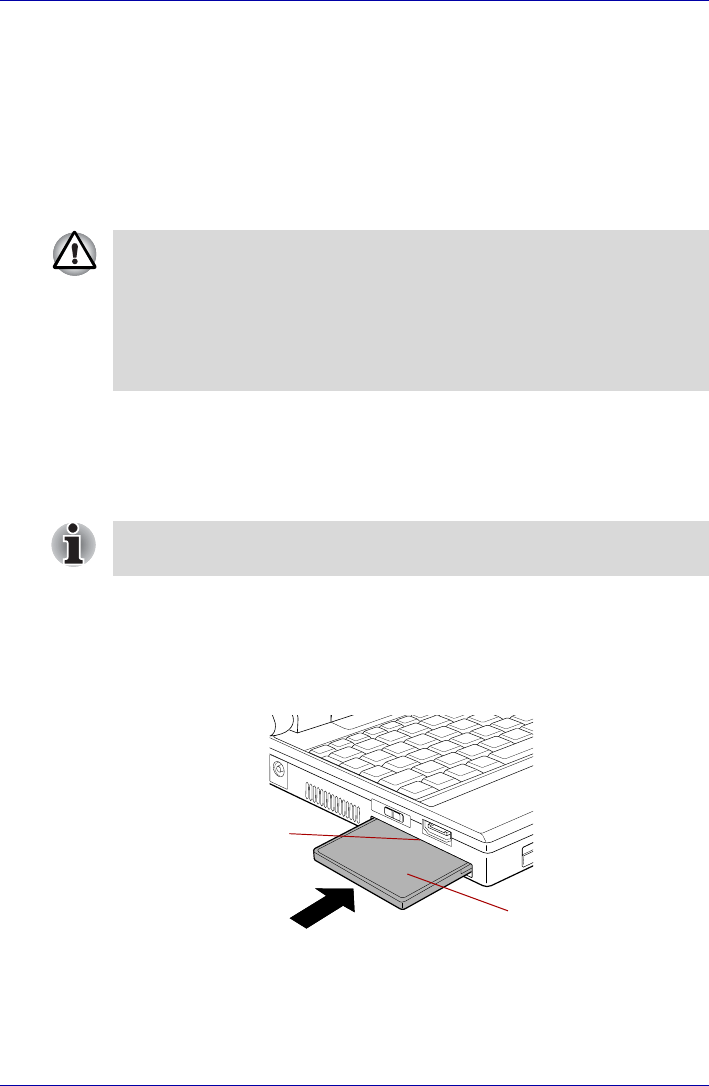
Inserting a PC card
The PC card slot is located on the left side of the computer.
Windows hot-install feature lets you insert PC cards while the computer’s
power is on.
To insert a PC card, follow the steps below:
1. Slide the extended eject latch to pop the Dummy card out slightly.
2. Grasp the Dummy card and draw it out.
3. Insert a PC card in the PC card slot.
4. Press gently to ensure a firm connection.
Figure 8-1 Inserting the PC card
5. After inserting the PC card, refer to the PC card’s documentation and
check the configuration in Windows to make sure it is appropriate for
your PC card.
■PC cards can sometimes become hot during PC operation. Before you
remove a PC card always wait for it to cool. You could get burned
removing a hot PC card.
■Keep foreign objects out of the PC card slot. Never allow metal objects,
such as screws, staples and paper clips, to enter the PC or keyboard.
Foreign metal objects can create a short circuit, which can cause PC
damage and fire, possibly resulting in serious injury.
Do not insert a PC card while the computer is in standby or hibernation
mode. Some cards might not work properly.
PC card
PC card slot
User’s Manual 8-3
Optional Devices
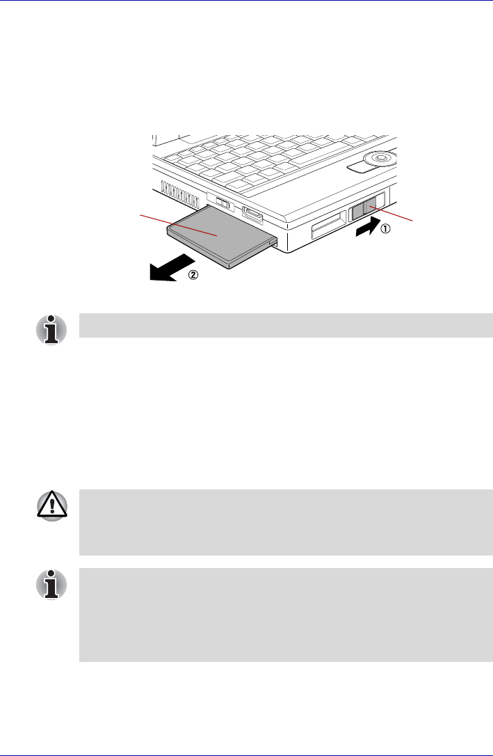
Removing a PC card
To remove the PC card, follow the steps below.
1. Open the Safely Remove Hardware icon on the Task Bar.
2. Point to PC card and click.
3. Slide the PC card eject lever to extend it.
4. Grasp the PC card and draw it out.
Figure 8-2 Removing the PC card
SD card
The computer is equipped with an SD card slot that can accommodate
Secure Digital flash memory cards with various memory capacities. SD
cards let you easily transfer data from devices, such as digital cameras and
Personal Digital Assistants, that use SD card flash-memory. The cards
have a high level of security and copy protection features. The slot cannot
accommodate Multi Media cards.
PC card PC card
eject lever
When you do not use a PC card, please be sure to insert a Dummy card.
Keep foreign objects out of the SD card slot. Never allow metal objects,
such as screws, staples and paper clips, to enter the PC or keyboard.
Foreign metal objects can create a short circuit, which can cause PC
damage and fire, possibly resulting in serious injury.
SD memory cards comply with SDMI (Secure Digital Music Initiative),
which is a technology adopted to prevent unlawful copy or playback of
digital music. For this reason, you cannot copy or playback protected
material on another computer or other device. You may not use the
reproduction of any copyrighted material except for your personal
enjoyment.
8-4 User’s Manual
Optional Devices
Formatting an SD memory card
SD memory cards are sold with format in conformity to the Standards of SD
memory card. If you format the SD card again, be sure to format it with the
utility of TOSHIBA SD memory card format, not in the format defined as the
Windows standard format.
In order to run TOSHIBA SD memory card format, click start, point to All
Programs, point to TOSHIBA, point to Utilities and click SD memory card
Format.
TOSHIBA SD memory card format does not format the protected area of
SD memory card. When you format all area of the SD memory card
including the protected area, use the application that responds to the copy
protection system.
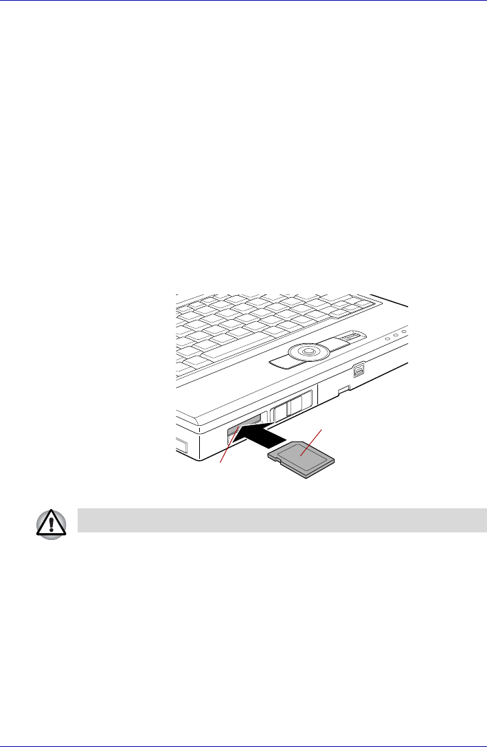
Inserting an SD card
To insert an SD card, follow the steps below.
1. Insert an SD card in the SD card slot.
2. Press gently to ensure a firm connection.
Figure 8-3 Inserting an SD card
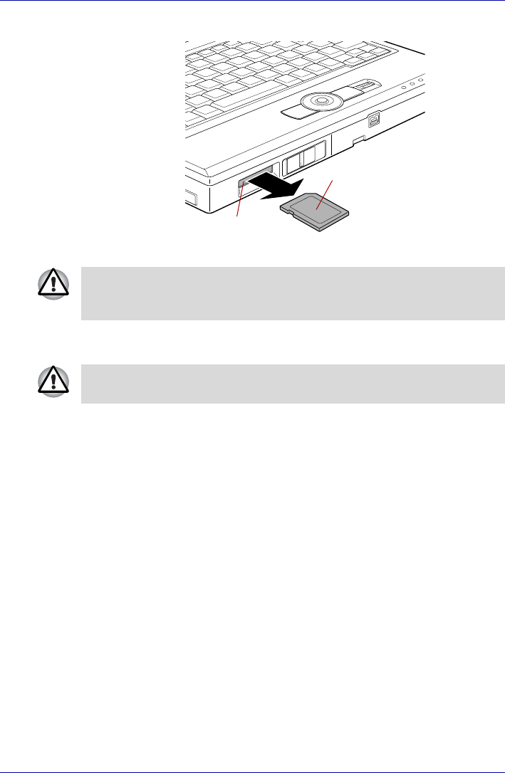
Removing an SD card
To remove an SD card, follow the steps below.
1. Open the Safely Remove Hardware icon on the Task Bar.
2. Point to SD card and click.
3. Push in the SD card and release it to pop the card out slightly.
SD card
SD card slot
Make sure the SD card is oriented properly before you insert it.
User’s Manual 8-5
Optional Devices
4. Grasp the SD card and remove it.
Figure 8-4 Removing an SD card
SD card care
1. Do not write to an SD card if the battery power is low. Low power could
affect writing accuracy.
2. Do not remove an SD card while read/write is in progress.
3. The SD card is designed so that it can be inserted only one way. Do not
try to force the SD card into the SD card slot.
4. Do not leave an SD card partially inserted in the slot. Press the SD card
until you hear it click into place.
5. Do not twist or bend SD cards.
6. Do not expose SD cards to liquids or store in humid areas or lay media
close to containers of liquid.
7. After using an SD card, return it to its case.
8. Do not touch the metal part or expose it to liquids or let it get dirty.
Creation of a boot disk
In TOSHIBA SD Memory Boot Utility, a boot disk can be created with SD
memory card. Refer to the Utilities of Chapter 1, Introduction for details.
SD card
SD card slot
Do not remove an SD card while the computer is in Standby or Hibernation
mode. The computer could become unstable or data in the SD card could
be lost.
Set the write-protect switch to the lock position, if you do not want to record
data.

8-6 User’s Manual
Optional Devices
Memory expansion
This computer has equipped the underside one memory module socket.
You can increase the capacity of RAM by installing a replacing default
memory with additional memories.
Some memory modules can be physically installed but are not compatible
with the computer. In this case, the computer will issue a warning. When
you turn on the power, a series of short beeps will sound in the pattern of
one, three, three, one. Shut down the power and remove the incompatible
module.
Installing memory module
Follow the steps below to install a memory module.
1. Set the computer to boot mode and turn the computer’s power off.
Make sure the Power indicator is off. Refer to the Turning off the power
section in Chapter 3, Getting Started.
2. Remove AC adaptor and all cables connected to the computer.
3. Turn the computer upside down and remove the battery pack. Refer to
Replacing the battery pack section in Chapter 6, Power and Power-Up
Modes, for details.
■Place a mat beneath the computer to prevent making a scratch on the
lid when replacing the memory module. Avoid the mat that generates
static electricity.
■When you remove a memory, please do not touch other portions of a
computer.
■Use only memory modules approved by TOSHIBA.
■Do not try to install or remove a memory module under the following
conditions. You can damage the computer and the module. Also, data
will be lost.
a. The computer is turned on.
b. The computer was shut down using the Standby mode or
Hibernation mode.
c. Wake-up on LAN is enabled.
■Be careful not to let screws or other foreign matter fall into the
computer. It could cause malfunction or electric shock.
■Expansion memory is a precision electronic component that may be
fatally damaged by static electricity. Since human body has slight static
electricity, be sure to discharge static electricity from your body before
installing an expansion memory module. To discharge your body’s
static electricity, simply touch any metal close to you with bare hands.
Use a point size 0 Phillips screwdriver to remove and fasten the screws.
Use of an incorrect screwdriver can damage the screw heads.
User’s Manual 8-7
Optional Devices
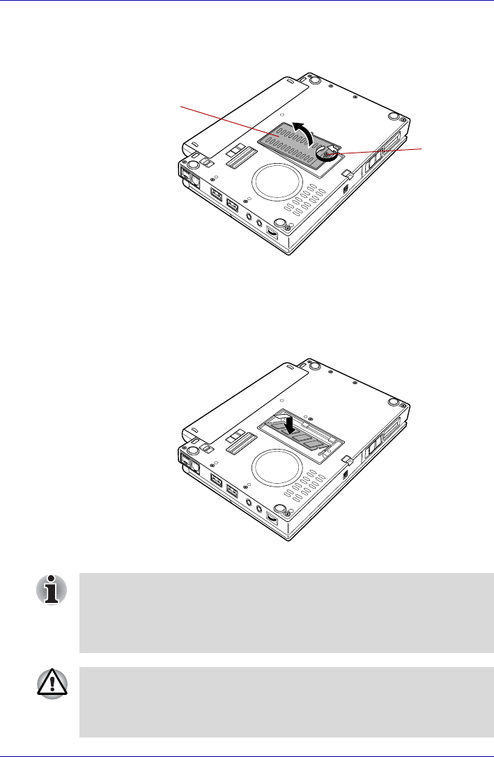
4. Loose a screw securing the memory module cover. The screw is
attached to the cover to prevent it from being lost.
5. Slide your fingernail or a thin object under the cover and lift it off.
Figure 8-5 Removing the memory module cover
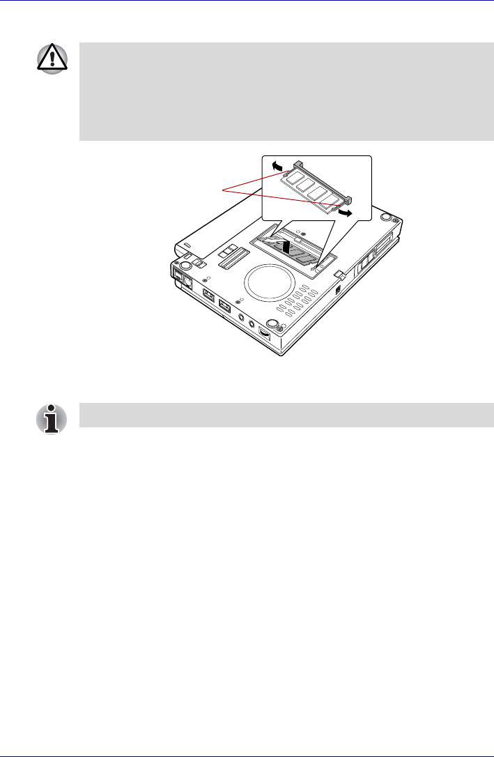
6. Fit the memory module’s connectors into the socket at about a 45
degree angle and push the module down until latches on either side
snap into place.
Align the notch of the memory module with that of the memory slot and
gently insert the module into the slot.
Figure 8-6 Seating the memory module
Screw
Memory module cover
Align the grooves of the memory module with the locking tabs of the
connector and insert the module into the connector firmly. If you find it
difficult to install the memory module, try to adjust the tabs of the connector
with a pen tip or other tools. Make sure to hold the memory module with
your fingers on the side edges (sides with grooves).
■Be careful not to drop the screw inside the computer.
■Do not touch the connectors on the memory module or on the
computer. Debris on the connectors may cause memory access
problems.
8-8 User’s Manual
Optional Devices
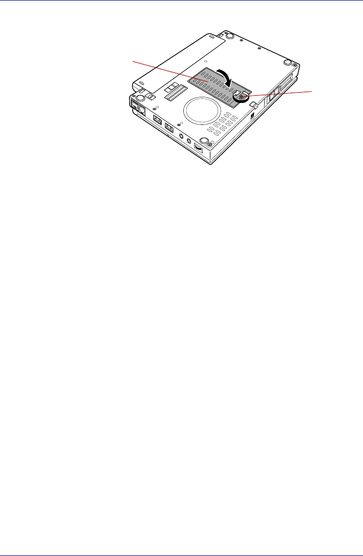
7. Seat the memory module cover and secure it with one screw.
Figure 8-7 Seating the memory module cover
8. Install the battery pack. Refer to Replacing the battery pack section in
Chapter 6, Power and Power-Up Modes, for details.
9. Return your computer to the upright position.
10. Turn the computer power on and make sure the added memory is
recognized.
Click start, click Control Panel, click Performance and Maintenance
and select the System icon. Open System Properties window and
click General tab.
Removing memory module
To remove the memory module, make sure the computer is in boot mode
then:
1. Set the computer to boot mode and turn the computer’s power off.
Make sure the Power indicator is off.
2. Remove AC adaptor and all cables connected to the computer.
3. Turn the computer upside down and remove the battery pack. Refer to
Replacing the battery pack section in Chapter 6, Power and Power-Up
Modes, for details.
4. Loose a screw securing the memory module cover. The screw is
attached to the cover to prevent it from being lost.
5. Slide your fingernail or a thin object under the cover and lift it off.
6. Push the latches to the outside to release the module. A spring will
force one end of the module up.
Memory module cover
Screw
User’s Manual 8-9
Optional Devices
7. Grasp the module by the sides and pull it out.
Figure 8-8 Removing the memory module
8. Seat the memory module cover and secure it with one screw.
9. Install the battery pack. Refer to Replacing the battery pack section in
Chapter 6, Power and Power-Up Modes, for details.
10. Return your computer to the upright position.
Battery pack
You can increase the portability of the computer with additional battery
packs. If you’re away from an AC power source and your battery runs low,
you can replace it with a freshly charged battery. Refer to Chapter 6, Power
and Power-Up Modes.
Universal AC adaptor
If you frequently transport the computer between different sites such as
your home and office, purchasing an AC adaptor for each location will
reduce the weight and bulk of your carrying load.
■If you use the computer for a long time, the memory modules and the
circuits located close to the memory modules will become hot. In this
case, let them cool to room temperature before you replace them.
■Do not touch the connectors on the memory module or on the
computer. Debris on the connectors may cause memory access
problems.
Latches
Be sure that the cover is closed firmly.
8-10 User’s Manual
Optional Devices
USB floppy disk drive
The USB floppy disk drive module can be connected to the USB port. For
details on connecting the USB floppy disk drive module, refer to Chapter 4,
Operating Basics.
External monitor
An external analog monitor can be connected to the Mini-RGB port on the
computer. The computer supports VGA and XGA video modes. To connect
a monitor, follow the steps below.
1. Turn the computer’s power off.
2. Connect the monitor cable to the Mini-RGB cable.
3. Connect the Mini-RGB cable to the Mini-RGB port.
Figure 8-9 Connecting the monitor cable to the Mini-RGB port
4. Turn the monitor’s power on.
5. Turn the computer’s power on.
When you turn on the power, the computer automatically recognizes the
monitor and determines whether it is color or monochrome.
However, the Windows Desktop appears on a display device that you used
last time to shut down your computer, if the display device exists when you
turn on the power.
To change the display settings, press FN + F5. If you disconnect the
external monitor before you turn the computer’s power off, be sure to press
FN + F5 to switch to the internal display. Refer to Chapter 5, The Keyboard,
for details on using hot keys to change the display setting.
Mini-RGB cable
Mini-RGB port

User’s Manual 8-11
Optional Devices
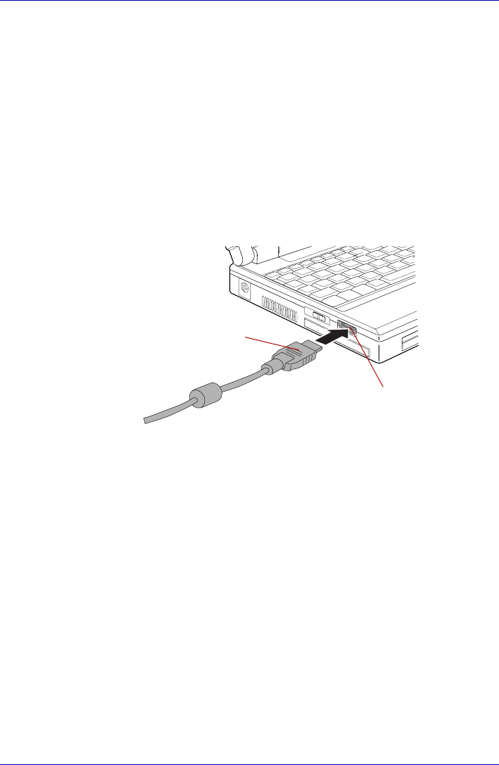
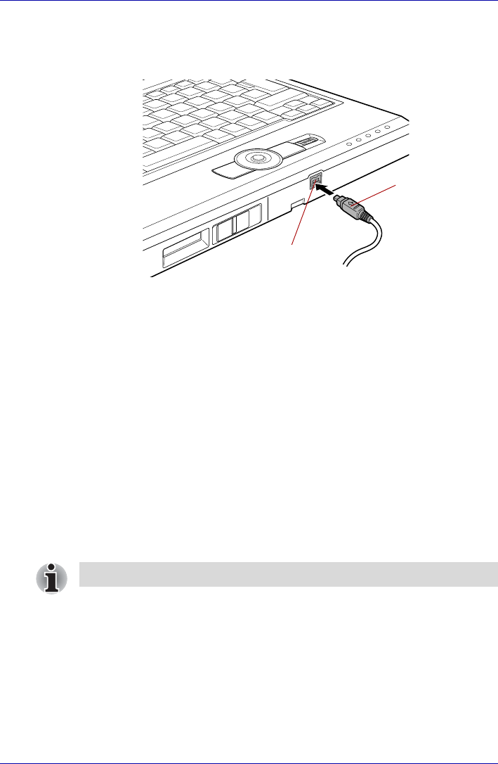
i.LINK (IEEE1394)
i.LINK (IEEE1394) is used for high-speed data transfer for a range of
compatible devices such as
■Digital video cameras
■Hard disk drives
■MO drives
■CD-RW drives
Precautions
■Make a back-up of your data before transferring it to the computer.
There is a possibility that the original data will be damaged. There is a
particular risk that some frames will be deleted in the case of digital
video transfer. TOSHIBA assumes no liability for such loss of data.
■Do not transfer data in areas where static electricity is easily generated
or in areas subjected to electronic noise. Data can be destroyed.
■If you are transferring data through an IEEE1394 hub, do not connect or
disconnect other devices from the hub during data transfer. There is a
likelihood that data will be damaged. Connect all devices to the hub
before you turn on the computer’s power.
■You may not use any copyrighted video or music data copied from a
video camera except for your personal enjoyment.
■If you connect/disconnect an i.LINK device to/from another i.LINK
device that is currently exchanging data with the computer, data frames
might be dropped.
■Make sure data transfer has ended or turn off the computer, before you:
■Connect/disconnect an i.LINK device to/from the computer.
■Connect/disconnect an i.LINK device to/from another i.LINK device
that is connected to the computer.
i.LINK uses a four-pin connector, which does not carry electric current.
External devices will need their own power supply.
8-12 User’s Manual
Optional Devices
Connecting
1. Make sure the connectors are properly aligned and plug the i.LINK
(IEEE1394) cable into the computer.
Figure 8-10 Connecting the i.LINK(IEEE1394) cable into the computer
2. Plug the other end of the cable into the device.
Note the following when you use i.LINK:
■You may need to install drivers for your i.LINK devices.
■Not all i.LINK devices have been tested. Therefore, compatibility with all
i.LINK devices cannot be guaranteed.
■Use i.LINK (IEEE1394) cable no longer than three meters.
■Some devices might not support standby or automatic off functions.
■Do not connect or disconnect an i.LINK device while it is using an
application or when the computer is automatically shutting it down to
save power. Data might be destroyed.
Disconnecting
1. Open the Safely Remove Hardware icon on the Task Bar.
2. Point to i.LINK (IEEE1394) device and click.
3. Disconnect the cable from the computer then from the i.LINK device.
i.LINK (IEEE1394)
connector
i.LINK
(IEEE1394) port
Refer also to the documentation that came with your i.LINK device.
User’s Manual 8-13
Optional Devices
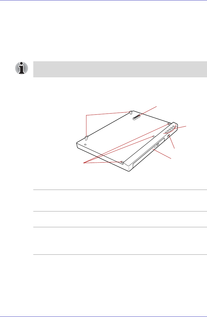
libretto DVD Dock
The optical media drive can be used by connecting the libretto DVD Dock
to this computer. This will allow the computer to view the CD/DVD, write
data to the CD-ROM or DVD-ROM, etc.
The full-size drive provides high-performance execution of CD/ DVD-ROM-
based programs. You can run either 12 cm (4.72") or 8 cm (3.15") CD/
DVDs without an adaptor.
Front and Left side
The following figure shows the libretto DVD Dock's front and left side.
Figure 8-11 Front and life side the libretto DVD Dock
Please end all applications or Express Media that are running before
installing/removing the libretto DVD Dock.
Front latches
Lock lever
Front operation
panel
Optical media
drive
Docking
connector
Hold switch
Lock lever Rotating this will lock the libretto DVD Dock
connected to the computer so that it cannot be
removed.
Docking connector This is the computer interface. It connects
directly to the computer's docking port.
Front operation
panel Five buttons are available for use: CD/DVD,
Play/Pause, Stop, Previous, Next. These buttons
allow you to manage Audio/Video, run
applications and access utilities.
8-14 User’s Manual
Optional Devices
CD/DVD button Pressing this button will launch an application
program that allows for watching CD/DVD.
Pressing this button in the power-off condition
will run Express Media Player. Once Express
Media Player is launched, and the front operation
panel button is enables. Meanwhile, when
Express Media Player is running, pressing this
button will do nothing. Pressing this button in the
power-on or standby conditions will launch
Windows Media Player/WinDVD.
Play/Pause button Press this button to begin or pause play.
Press this button to run Windows Media Player/
WinDVD. When Windows Media Player/WinDVD
was already running, this button becomes to
Play/Pause function.
STOP button Press this button to stop play.
Previous button Press this button to advances to the previous
track, chapter or data.
Next button Press this button to advances to the next track,
chapter or data.
Hold switch Locking this will prevent unintended button
operations. Slide to the right to unlock and slide
to the left to lock (hold).
Front Latches Three latches at the front of the libretto DVD
Dock are connected with three holes in the front
part of computer. It is used when connecting
computer to libretto DVD Dock.
Optical media drive The libretto DVD Dock is configured with a DVD-
ROM&CD-R/RW drive or a DVD Super Multi
drive.
User’s Manual 8-15
Optional Devices
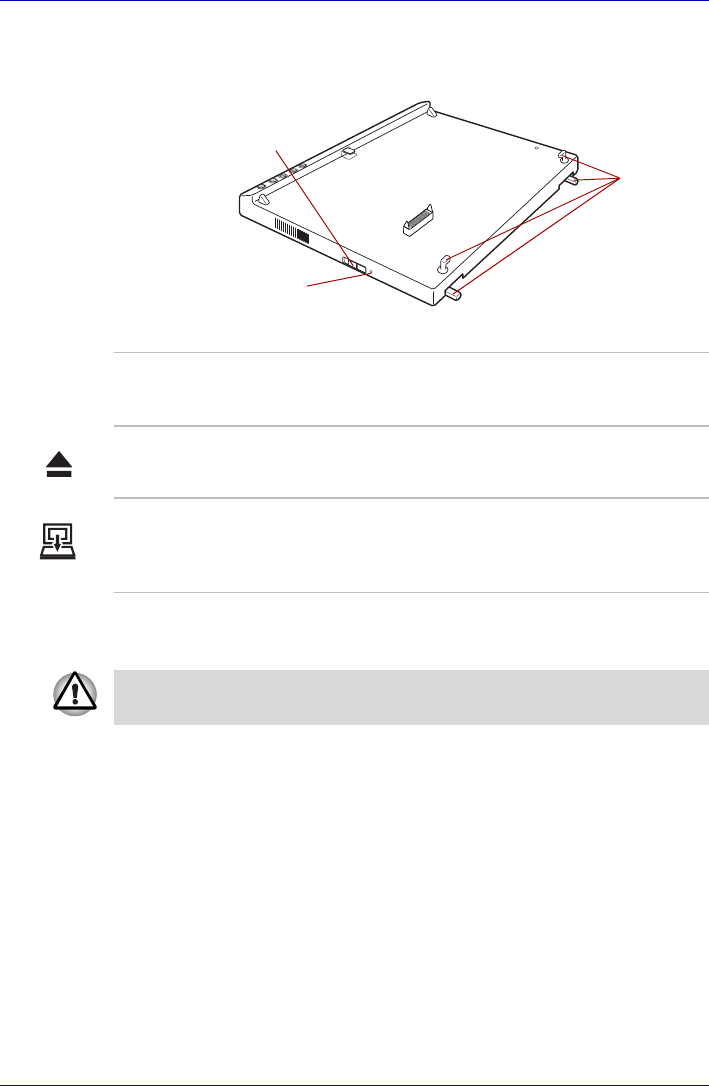
Right side and Back side
The following figure shows the libretto DVD Dock's right and back side.
Figure 8-12 Right and back side the libretto DVD Dock
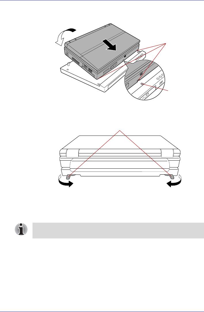
Connecting the libretto DVD Dock
Follow the steps below to connect the computer to the libretto DVD Dock.
1. Turn the computer's power off.
2. Disconnect all cables connected to the computer.
3. Place the computer on the libretto DVD Dock so that the Docking holes
of the front-side of the computer are aligned with the libretto DVD
Dock's Front Latches.
Undock switch
Docking LED
Lock lever
Lock lever Rotating this will lock the libretto DVD Dock
connected to the computer so that it cannot be
removed.
Undock switch Slide this to eject the computer. Slide to the left to
eject.
Docking LED This indicator is lit up when the libretto DVD Dock
is connected to the computer. When the eject
operation is carried out, check that this indicator
is not lit before removing it.
Before you connect the libretto DVD Dock, make sure you turn off the
computer and disconnect the AC Adaptor and any other external devices.
8-16 User’s Manual
Optional Devices
4. Gently press the computer downward to connect the computer's
docking interface to the libretto DVD Dock's docking interface.
Figure 8-13 Connecting the computer to the libretto DVD Dock.
5. Close the lock lever to secure the libretto DVD Dock to the computer.
Figure 8-14 Closing the lock lever
Disconnecting the libretto DVD Dock
Follow the steps below to disconnect the computer to the libretto DVD
Dock.
1. Save your work.
2. Turn the computer's power off. Make sure the Power indicator is off.
3. Remove all cables connected to the computer.
Docking holes
libretto DVD
Dock's front
latch
Lock lever
When removing the libretto DVD Dock, switch off the power to the main
computer unit before sliding the Undock switch.

User’s Manual 8-17
Optional Devices
4. Open the lock lever.
Figure 8-15 Opening the lock lever
5. First lift the backside of the computer, remove the computer.
Lock lever

8-18 User’s Manual
Optional Devices

User’s Manual 9-1
libretto U100
Chapter 9
Troubleshooting
TOSHIBA designed the computer for durability. However, should problems
occur, following the procedures in this chapter can help to determine the
cause.
All readers should become familiar with this chapter. Knowing what might
go wrong can help prevent problems from occurring.
Problem solving process
Resolving problems will be much easier if you observe the following
guidelines:
■Stop immediately when you recognize a problem exists. Further action
may result in data loss or damage. You may destroy valuable problem-
related information that can help solve the problem.
■Observe what is happening. Write down what the system is doing and
what actions you performed immediately before the problem occurred.
If you have a printer attached, print a copy of the screen using PRTSC.
The questions and procedures offered in this chapter are meant as a guide,
they are not definitive problem solving techniques. Many problems can be
solved simply, but a few may require help from your dealer. If you find you
need to consult your dealer or others, be prepared to describe the problem
in as much detail as possible.

9-2 User’s Manual
Troubleshooting
Preliminary checklist
Consider the simplest solution first. The items in this checklist are easy to
fix and yet can cause what appears to be a serious problem.
■Make sure you turn on all peripheral devices before you turn on the
computer. This includes your printer and any other external device you
are using.
■Before you attach an external device, turn the computer off. When you
turn the computer back on it recognizes the new device.
■Make sure all options are set properly in the setup program.
■Check all cables. Are they correctly and firmly attached? Loose cables
can cause signal errors.
■Inspect all connecting cables for loose wires and all connectors for
loose pins.
■Check that your floppy disk or CD/DVD-ROM is correctly inserted and
that the floppy disk’s write protect tab is correctly set.
Make notes of your observations and keep them in a permanent error log.
This will help you describe your problems to your dealer. If a problem
recurs, the log will help you identify the problem faster.
Analyzing the problem
Sometimes the system gives clues that can help you identify why it is
malfunctioning. Keep the following questions in mind:
■Which part of the system is not operating properly: keyboard, floppy
disk drives, hard disk drive, optical media drive, display. Each device
produces different symptoms.
■Is the operating system configuration set properly? Check the
configuration options.
■What appears on the display screen? Does it display any messages or
random characters? If you have a printer attached, print a copy of the
screen using PRTSC. Look up the messages in the software and
operating system documentation. Check that all connecting cables are
correctly and firmly attached. Loose cables can cause erroneous or
intermittent signals.
■Do any indicators light? Which ones? What color are they? Do they stay
on or blink? Write down what you see.
■Do you hear any beeps? How many? Are they long or short? Are they
high pitched or low? Is the computer making any unusual noises? Write
down what you hear.
Record your observations so you can describe them to your dealer.

User’s Manual 9-3
Troubleshooting
Hardware and system checklist
This section discusses problems caused by your computer’s hardware or
attached peripherals. Basic problems may occur in the following areas:
System start-up
When the computer does not start properly, check the following items:
■Self Test
■Power Sources
■Power-on Password
Software The problems may be caused by your software or disk. If
you cannot load a software package, the media may be
damaged or the program might be corrupted. Try loading
another copy of the software.
If an error message appears while you are using a software
package, check the software documentation. These
documents usually include a problem solving section or a
summary of error messages.
Next, check any error messages in the OS documentation.
Hardware If you cannot find a software problem, check your
hardware. First run through the items in the preliminary
checklist above. If you still cannot correct the problem, try
to identify the source. The next section provides checklists
for individual components and peripherals.
Before using a peripheral device or application software that is not an
authorized Toshiba part or product, make sure the device or software can
be used with your PC. Use of incompatible devices may cause injury or
may damage your PC.
■System start-up
■Self test
■Power
■Password
■Keyboard
■Internal LCD display panel
■Hard disk drive
■DVD-ROM&CD-R/RW drive
■DVD Super Multi drive
■USB floppy disk drive
■SD card
■PC card
■Pointing device
■USB
■Fingerprint Sensor
■Memory expansion
■Sound system
■External monitor
■i.LINK (IEEE1394)
■Modem
■LAN
■Wireless LAN
■Bluetooth

9-4 User’s Manual
Troubleshooting
Self test
When the computer starts up, the self test will be run automatically, and the
following will be displayed:
This message remains on the screen for a few seconds.
If the self test is successful, the computer tries to load the operating
system, depending on how the Boot Priority is set in the TOSHIBA HW
Setup program.
If any of the following conditions are present, the self test failed:
■The computer stops and does not proceed to display information or
messages except the TOSHIBA logo.
■Random characters appear on the screen, and the system does not
function normally.
■The screen displays an error message.
Turn off the computer and check all cable connections. If the test fails
again, contact your dealer.
Power
When the computer is not plugged into an AC outlet, the battery pack is the
primary power source. However, your computer has a number of other
power resources, including intelligent power supply, Real Time Clock
battery. These resources are interrelated and any one could affect
apparent power problems. This section provides checklists for AC power
and the battery. If you cannot resolve a problem after following them, the
cause could lie with another power resource. In such case, contact your
dealer.
Overheating power down
If the computer’s internal temperature becomes too high, the computer will
automatically enter Hibernation or Resume mode and shut down.
SIn Touch with Tomorrow
TOSHIBA
Problem Procedure
Computer shuts down
and DC IN indicator
blinks orange
Leave the computer off until the DC IN indicator
stops blinking.
It is recommended to leave the computer off until the its interior reaches
room temperature even though the DC IN indicator stops blinking.

User’s Manual 9-5
Troubleshooting
AC power
If you have trouble turning on the computer with the AC adaptor connected,
check the DC IN indicator. Refer to Chapter 6, Power and Power-Up
Modes for more information.
Battery
If you suspect a problem with the battery, check the DC IN indicator as well
as the Battery indicator. For information on indicators and battery
operation see Chapter 6, Power and Power-Up Modes.
If the computer has reached room temperature
and still does not start, or if it starts but shuts
down quickly contact your dealer.
Computer shuts down
and its DC IN indicator
is flashing in green
Indicates a problem with the heat dispersal
system. Please contact your dealer.
Problem Procedure
AC adaptor doesn’t
power the computer
(DC IN indicator does
not glow green)
Check the connections. Make sure the cord is
firmly connected to the computer and a power
outlet.
Check the condition of the cord and terminals. If
the cord is frayed or damaged, replace it. If the
terminals are soiled, wipe them with cotton or a
clean cloth.
If the AC adaptor still does not power the
computer, contact your dealer.
Problem Procedure
Battery doesn’t power
the computer The battery may be discharged. Connect the AC
adaptor to charge the battery.

9-6 User’s Manual
Troubleshooting
Battery doesn’t charge
when the AC adaptor
is attached (Battery
indicator does not
glow in orange.)
If the battery is completely discharged, it will not
begin charging immediately. Wait a few minutes.
If the battery still does not charge, make sure the
outlet of the AC adaptor is supplying power.
Test it by plugging in an appliance.
Check whether the battery is hot or cold to the
touch. If the battery is too hot or too cold, it will
not charge properly. Let it reach room
temperature.
Unplug the AC adaptor and remove the battery to
make sure the terminals are clean. If necessary
wipe them with a soft dry cloth dipped in alcohol.
Connect the AC adaptor and replace the battery.
Make sure it is securely seated.
Check the Battery indicator. If it does not glow,
let the computer charge the battery for at least 20
minutes. If the Battery indicator glows after 20
minutes, let the battery continue to charge at
least another 20 minutes before turning on the
computer.
If the indicator still does not glow, the battery may
be at the end of its operating life. Replace it.
If you do not think the battery is at the end of its
operating life, see your dealer.
Battery doesn’t power
the computer as long
as expected
If you frequently recharge a partially charged
battery, the battery might not charge to its full
potential. Fully discharge the battery, then try to
charge it again.
Check the power consumption settings in
TOSHIBA Power Saver utility. Consider using a
power saving mode.
Problem Procedure

User’s Manual 9-7
Troubleshooting
Real Time Clock
Password
Keyboard
Keyboard problems can be caused by your setup configuration. For more
information refer to Chapter 5, The Keyboard.
Problem Procedure
The following
message is Displayed
on the LCD screen:
RTC battery is
low or CMOS
checksum is
inconsistent.
Press [F1] key to
set Date/Time.
The battery for RTC is wearing. Set the date and
time in BIOS setup with the following steps:
1. Press F1 key. BIOS setup will boot up.
2. Set the date in System Date.
3. Set the time in System Time.
4. Press END key. Confirmation message will
appear.
5. Press Y key. BIOS setup will terminate and
the computer will be rebooted.
Problem Procedure
Cannot enter
password Refer to the TOSHIBA Password Utility section in
Chapter 6, Power and Power-Up Modes.
Problem Procedure
Some letter keys
produce numbers Check that the numeric keypad overlay is not
selected. Press FN + F11 and try typing again.
Output to screen is
garbled Make sure the software you are using is not
remapping the keyboard. Remapping involves
reassigning the meaning of each key. See your
software’s documentation.
If you are still unable to use the keyboard,
consult your dealer.

9-8 User’s Manual
Troubleshooting
Internal LCD display panel
Apparent LCD problems may be related to the computer’s setup. Refer to
Chapter 7, HW Setup, for more information.
Hard disk drive
Problem Procedure
No display Press hotkeys FN + F5 to change the display
priority, to make sure it is not set for an external
monitor.
Markings appear on the
LCD screen. They might have come from contact with the
keyboard, AccuPoint wiping the LCD screen
gently with a clean dry cloth. If markings remain,
use LCD screen cleaner. Be sure to let the LCD
screen dry before closing it.
Problems above
remain unresolved or
other problems occur
Refer to your software’s documentation to
determine if the software is causing the difficulty.
Run the diagnostic test.
Contact your dealer if the problems continue.
Problem Procedure
Computer does not
boot from hard disk
drive
Check if a floppy disk is in the floppy disk drive or
a CD-ROM is in the optical media drive. Remove
any floppy disk and/or CD-ROM and check Boot
priority. Refer to the Boot Priority section in
Chapter 7, HW Setup.
There may be a problem with your operating
system files. Refer to your OS documentation.
Slow performance Your files may be fragmented. Run Disk
Defragmenter to check the condition of your files
and disk. Refer to your OS documentation or
online HELP for information on running the Disk
Defragmenter.
As a last resort, reformat the hard disk. Then,
reload the operating system and other files.
If problems persist, contact your dealer.

User’s Manual 9-9
Troubleshooting
DVD-ROM&CD-R/RW drive
For more information, refer to Chapter 4, Operating Basics.
Problem Procedure
You cannot access a
CD/DVD in the drive Make sure the drive’s disc tray is securely
closed. Press gently until it clicks into place.
Check whether the drive power is on. If the
power is off, click on the optical media drive icon
in the task tray and turn on the power.
Open the disc tray and make sure the CD/DVD is
properly seated. It should lie flat with the label
facing up.
A foreign object in the disc tray could block laser
light from reading the CD/DVD. Make sure there
is no obstruction. Remove any foreign object.
Check whether the CD/DVD is dirty. If it is, wipe it
with a clean cloth dipped in water or a neutral
cleaner. Refer to the Media care section in
Chapter 4 for details on cleaning.
Some CD/DVDs run
correctly, but others do
not
The software or hardware configuration may be
causing a problem. Make sure the hardware
configuration matches your software’s needs.
Check the CD/DVD’s documentation.
Check the type of CD/DVD you are using. The
drive supports:
DVD-ROM: DVD-ROM, DVD-Video
CD-ROM: CD-DA, CD-Text, Photo CDTM
(single/multi-session), CD-
ROM Mode 1, Mode 2, CD-
ROM XA Mode 2 (Form1,
Form2), Enhanced CD (CD-
EXTRA), Addressing Method 2
Recordable CD: CD-R, CD-RW
Check the region code on the DVD. It must
match that on the DVD-ROM&CD-R/RW drive.
Region codes are listed in the Optical media
drives section in Chapter 2, The Grand Tour.

9-10 User’s Manual
Troubleshooting
DVD Super Multi drive
For more information, refer to Chapter 4, Operating Basics.
Cannot write correctly If you have trouble writing, make sure you are
observing the following precautions:
■Use only media recommended by TOSHIBA.
■Do not use the mouse or keyboard during
writing.
■Use only the software supplied with the
computer for recording.
■Do not run or start other software during
writing.
■Do not jar the computer during writing.
■Do not connect/disconnect external devices
or install/remove internal cards during writing.
If problems persist, contact your dealer.
Problem Procedure
Problem Procedure
You cannot access
a CD/DVD in the drive
Make sure the drive’s disc tray is securely
closed.
Press gently until it clicks into place.
Check whether the drive power is on. If the
power is off, click on the optical media drive icon
in the task tray and turn on the power.
Open the disc tray and make sure the CD/DVD is
properly seated. It should lie flat with the label
facing up.
A foreign object in the disc tray could block laser
light from reading the CD/DVD. Make sure there
is no obstruction. Remove any foreign object.
Check whether the CD/DVD is dirty. If it is, wipe it
with a clean cloth dipped in water or a neutral
cleaner. Refer to the Media care section in
Chapter 4 for details on cleaning.
Some CD/DVDs run
correctly, but others do
not
The software or hardware configuration may be
causing a problem. Make sure the hardware
configuration matches your software’s needs.
Check the CD/DVD’s documentation.

User’s Manual 9-11
Troubleshooting
USB floppy disk drive
For more information, refer to Chapter 4, Operating Basics.
SD card
Refer also to Chapter 8, Optional Devices.
Check the type of CD/DVD you are using. The
drive supports:
DVD-ROM: DVD-ROM, DVD-Video
CD-ROM: CD-DA, CD-Text, Photo CDTM
(single/multi-session), CD-ROM
Mode 1, Mode 2, CD-ROM XA
Mode 2 (Form1, Form2), Enhanced
CD (CD-EXTRA), Addressing
Method 2
Check the region code on the DVD. It must
match that on the DVD Super Multi drive. Region
codes are listed in the Optical media drives
section in Chapter 2, The Grand Tour.
Problem Procedure
Drive does not operate There may be a faulty cable connection. Check
the connection to the computer and to the drive.
Some programs run
correctly but others do
not
The software or hardware configuration may be
causing a problem. Make sure the hardware
configuration matches your software needs.
You cannot access the
external 3 1/2" floppy
disk drive
Try another floppy disk. If you can access the
floppy disk, the original floppy disk (not the drive)
is probably causing the problem.
If problems persist, contact your dealer.
Problem Procedure
SD card error occurs Reseat the SD card to make sure it is firmly
connected.
Check the card’s documentation.
You cannot write to an
SD memory card Make sure the card is not write protected.
You cannot read a file Make sure the target file is on the SD memory
card inserted in the slot.
If problems persist, contact your dealer.

9-12 User’s Manual
Troubleshooting
PC card
Refer also to Chapter 8, Optional Devices.
Pointing Device
If you are using a USB mouse, also refer to the USB section in this chapter
and to your mouse documentation.
AccuPoint
Problem Procedure
PC card error occurs Reseat the PC card to make sure it is firmly
connected.
Make sure the connection between the external
device and the card is firm.
Check the card’s documentation.
If problems persist, contact your dealer.
Problem Procedure
Either the the
AccuPoint does not
work.
Check the Device Select settings. Click start,
click Control Panel, click Printers and Other
Hardware and select Mouse icon. Open the
Mouse Properties and click Dual Pointing
Device tab. Then click the Detail Setting button
and click the Device Select tab.
On-screen pointer
does not respond to
Pad operation
The system might be busy. If the pointer is
shaped as an hourglass, wait for it to resume its
normal shape and try again to move it.
The mouse pointer
moves too fast or too
slow
Try changing the speed setting in the mouse
control utility.
1. Click start, click Control Panel, click
Printers and Other Hardware and select
Mouse icon.
2. Click the Pointer Options tab.
3. Set the speed as instructed and click OK.

User’s Manual 9-13
Troubleshooting
Fingerprint Sensor
USB mouse
Double-clicking
(AccuPoint control
buttons) does not work
Try changing the double-click speed setting in
the mouse control utility.
1. Click start, click Control Panel, click
Printers and Other Hardware and select
Mouse icon.
2. Click the Buttons tab.
3. Set the double-click speed as instructed and
click OK.
If problems persist, contact your dealer.
Problem Procedure
Problem Procedure
Reading of the
fingerprint was not
successful.
Please try again using the correct posture. Refer
to Using the Fingerprint Sensor in Chapter 4,
Operating Basics.
Please try reading the fingerprint again using
another enrolled finger.
The fingerprint cannot
be read due to injuries
to the finger.
Please try reading the fingerprint using another
enrolled finger.
If fingerprints from all the enrolled fingers cannot
be read, please logon by using the keyboard to
input the password for the time being.
If problems persist, contact your dealer.
Problem Procedure
On-screen pointer
does not respond to
mouse operation
The system might be busy. If the pointer is
shaped as an hourglass, wait for it to resume its
normal shape and try again to move it.
Make sure the mouse is properly connected to
the USB port.
Double-clicking does
not work Try changing the double-click speed setting in
the mouse control utility.
1. Click start, click Control Panel, click
Printers and Other Hardware and select
Mouse icon.
2. Click the Buttons tab.
3. Set the double-click speed as instructed and
click OK.

9-14 User’s Manual
Troubleshooting
USB
Refer also to your USB device’s documentation.
The mouse pointer
moves too fast or too
slow
Try changing the speed setting in the mouse
control utility.
1. Click start, click Control Panel, click
Printers and Other Hardware and select
Mouse icon.
2. Click the Pointer Options tab.
3. Set the speed as instructed and click OK.
The mouse pointer
moves erratically The mouse might be dirty. Refer to your mouse
documentations for instructions on cleaning.
If problems persist, contact your dealer.
Problem Procedure
Problem Procedure
USB device does not
work Check for a firm cable connection between the
USB ports on the computer and the USB device.
Make sure the USB device drivers are properly
installed. Refer to your Windows XP
documentation for information on checking the
drivers.
If you are using an operating system that does
not support USB, you can still use a USB mouse
and/or USB keyboard. If these devices do not
work, make sure the USB KB/Mouse Legacy
Emulation item in HW Setup is set to Enabled.
If problems persist, contact your dealer.

User’s Manual 9-15
Troubleshooting
Memory expansion
Refer also to Chapter 8, Optional Devices, for information on installing
memory modules.
Sound System
Refer also to documentation for your audio devices.
Problem Procedure
Beep sounds.
(Two beeps, a dash
and a dot, for a
defective memory
module in slot.)
Make sure the memory module installed in the
memory slot is compatible with the computer.
If an incompatible module has been installed,
follow the steps below.
1. Turn off the computer.
2. Disconnect the AC adaptor and all peripheral
devices.
3. Remove the battery pack.
4. Remove the memory module.
5. Install the battery and/or connect the AC
adaptor.
6. Turn on the power.
If problems persist, contact your dealer.
Problem Procedure
No sound is heard Adjust the volume control dial.
Check the software volume settings.
Make sure the headphone connection is secure.
Check Windows Device Manager. Make sure the
sound function is enabled and that settings for I/
O address, Interrupt level and DMA are correct
for your software and do not conflict with other
hardware devices that you may have connected
to the computer.
If problems persist, contact your dealer.

9-16 User’s Manual
Troubleshooting
External monitor
Refer also to Chapter 8, Optional Devices, and to your monitor’s
documentation.
i.LINK (IEEE1394)
Modem
Refer to Appendix C, AT Commands and Appendix D, S-registers.
Problem Procedure
Monitor does not turn
on Make sure that the external monitor’s power
switch is on. Confirm that the external monitor’s
power cable is plugged into a working power
outlet.
No display Try adjusting the contrast and brightness controls
on the external monitor.
Press hot keys FN + F5 to change the display
priority and make sure it is not set for the internal
LCD.
Display error occurs Check that the cable connecting the external
monitor to the computer is attached firmly.
If problems persist, contact your dealer.
Problem Procedure
i.LINK device does not
function Make sure the cable is securely connected to the
computer and to the device.
Make sure the device’s power is turned on.
Reinstall the drivers. Open the Windows
Control Panel and double-click the Add
Hardware icon. Follow the on-screen
directions.
Restart Windows.
If problems persist, contact your dealer.
Problem Procedure
Communication
software can’t initialize
modem
Make sure the computer’s internal modem
settings are correct. Refer to Phone and Modem
Properties in the Control Panel.

User’s Manual 9-17
Troubleshooting
LAN
You can hear a dial
tone but can’t make a
call
If the call is going through a PBX machine, make
sure the communication application’s tone dial
detection feature is disabled.
You can also use the ATX command. Refer to
Appendix C, AT Commands.
You place a call, but a
connection can’t be
made
Make sure the settings are correct in your
communications application.
After making a call you
can’t hear a ring Make sure the tone or pulse selection in your
communications application is set correctly.
You can also use the ATD command. Refer to
Appendix C, AT Commands.
Communication is cut
off unexpectedly The computer will automatically cut off
communication when connection with the carrier
is not successful for a set time interval. Try
lengthening this time interval.
A CONNECT display is
quickly replaced by NO
CARRIER
Check the error control setting in your
communications application.
You can also use the AT\N command. Refer to
Appendix C, AT Commands.
Character display
becomes garbled
during a
communication
In data transmission, make sure the parity bit and
stop bit settings correspond with those of the
remote computer.
Check the flow control and communication
protocol.
You cannot receive an
incoming call Check the rings before auto answer setting in
your communications application.
You can also use the ATS0 command. Refer to
Appendix D, S-registers.
If problems persist, contact your dealer.
Problem Procedure
Problem Procedure
Cannot access LAN Check for a firm cable connection between the
LAN jack and the LAN HUB.
Wake-up on LAN does
not work Make sure the AC adaptor is connected. The
Wake-up on LAN function consumes power even
when the system is off.
If problems persist, consult your LAN
administrator.

9-18 User’s Manual
Troubleshooting
Wireless LAN
If the following procedures do not restore LAN access, consult your LAN
administrator. For more information on wireless communication, refer to
Chapter 4, Operating Basics.
Bluetooth
For more information on wireless communication, refer to Chapter 4,
Operating Basics.
Problem Procedure
Cannot access
Wireless LAN Make sure the computer’s wireless
communication switch is set to on.
If problems persist, contact your LAN
administrator.
Problem Procedure
Cannot access
Bluetooth device Make sure the computer’s wireless
communication switch is set to on.
Make sure the Bluetooth Manager is running and
the power to the Bluetooth device is turned on.
Make sure no optional Bluetooth PC card and
Bluetooth SD card are installed in the computer.
The built-in Bluetooth function and an optional
Bluetooth PC card cannot operate
simultaneously. If problems persist, contact your
dealer.

User’s Manual 9-19
Troubleshooting
Disposing of PC and PC batteries
■Discard this PC in accordance with ordinances or rules of local
regulations. For further information, contact your local government.
■This PC contains rechargeable batteries. After repeated use, the
batteries will finally lose their ability to hold a charge and you will need
to replace them. Under certain applicable laws and regulation, it may be
illegal to dispose of old batteries by placing them in the trash.
■Please be kind to our shared environment. Check with your local
government authority for details regarding where to recycle old
batteries or how to dispose of them properly. This product contains
mercury. Disposal of this material may be regulated due to
environmental considerations. For disposal, reuse or recycling
information, please contact your local government.
■If your hard disk or other storage media contains sensitive data, you
should be aware that standard deletion procedures do not remove data
from the media. These standard deletion procedures include:
■Selecting Delete for a target file
■Putting files in the Recycle Bin and emptying the Recycle Bin
■Reformatting the media
■Reinstalling an operating system from the recovery CD-ROM
The procedures above delete only the initial part of the data used for file
management. This makes the file invisible to the operating system, but
the data can still be read by specialized utilities. If you dispose of the
PC, please delete all the data on its HDD. Doing so prevents
unauthorized use of such data. To ensure your data is not used for
unauthorized purposes, you can:
■Physically destroy the HDD
■Use a proven specialized utility to overwrite all data
■Take the HDD to a professional deletion service
All data deletion costs will be borne by you.
TOSHIBA support
If you require any additional help using your computer or if you are having
problems operating the computer, you may need to contact TOSHIBA for
additional technical assistance.
Before you call
Some problems you experience may be related to software or the operating
system, it is important to investigate other sources of assistance first.
Before contacting TOSHIBA, try the following:
■Review troubleshooting sections in the documentation for software and
peripheral devices.

9-20 User’s Manual
Troubleshooting
■If a problem occurs when you are running software applications, consult
the software documentation for troubleshooting suggestions. Call the
software company’s technical support for assistance.
■Consult the dealer you purchased your computer and/or software from.
They are your best sources for current information and support.
Where to write
If you are still unable to solve the problem and suspect that it is hardware
related, write to TOSHIBA at the nearest location listed below:
Outside of Europe In Europe
Australia
TOSHIBA Australia Pty. Ltd.
Information Systems Division
84-92 Talavera Road
North Ryde N.S.W. 2113
Sydney
Germany & Austria
TOSHIBA Europe (I.E.) GmbH
Geschäftsbereich,
Deutschland-Österreich
Hammfelddamm 8,
D-41460 Neuss, Germany
Canada
TOSHIBA of Canada Ltd.
191 McNabb Street,
Markham, Ontario
L3R 8H2
France
TOSHIBA Systèms France S.A.
7, Rue Ampère B.P. 131,
92804 Puteaux Cedex
China
TOSHIBA Personal Computer &
Network (Shanghai) Co., Ltd.
43F, Hong Kong New World Tower,
No. 300 Huaihai Zhong Road,
Shanghai, P. R . China 200021
Netherlands
TOSHIBA Information Systems,
Benelux B.V.
Rivium Boulevard
41 2909 LK Capelle a/d IJssel
Singapore
TOSHIBA Singapore Pte. Ltd.
438B Alexandra Road #06-01
Alexandra Technopark
Singapore 119968
Spain
TOSHIBA Information Systems,
ESPAÑA
Parque Empresarial San Fernando
Edificio Europa, la Planta,
Escalera A 28830 Madrid

User’s Manual 9-21
Troubleshooting
United States of America
TOSHIBA America Information
Systems, Inc.
9740 Irvine Boulevard
Irvine, California 92618
USA
United Kingdom
TOSHIBA Information Systems
(U.K.) Ltd.
TOSHIBA Court
Weybridge Business Park
Addlestone Road
Weybridge, Surrey KT15 2UL
The Rest of Europe
TOSHIBA Europe (I.E.) GmbH
Geschäftsbereich,
Deutschland-Österreich
Hammfelddamm 8,
D-41460 Neuss, Germany
Outside of Europe In Europe

9-22 User’s Manual
Troubleshooting

User’s Manual 10-1
libretto U100
Chapter 10
Disclaimers
This chapter states the Disclaimers information applicable to TOSHIBA
computers. In the text in this manual, *XX is used to show which Disclaimer
description is related to TOSHIBA computers.
Descriptions related to this computer are marked with a blue *XX in this
manual. Clicking on *XX will display the related description.
LCD
*1
Over a period of time, and depending on the usage of the computer, the
brightness of the LCD screen will deteriorate. This is an intrinsic
characteristic of LCD technology.
Maximum brightness is only available when operating in AC power mode.
Screen will dim when the computer is operated on battery power and you
will not be able to increase the brightness of the screen.
CPU
*2
Central Processing Unit (“CPU”) Performance Disclaimer.
CPU performance in your computer product may vary from specifications
under the following conditions:
■use of certain external peripheral products
■use of battery power instead of AC power
■use of certain multimedia, computer generated graphics or video
applications
■use of standard telephone lines or low speed network connections
■use of complex modeling software, such as high end computer aided
design applications
■use of several applications or functionalities simultaneously
■use of computer in areas with low air pressure (high altitude >1,000
meters or >3,280 feet above sea level)

10-2 User’s Manual
Disclaimers
■use of computer at temperatures outside the range of 5°C to 30°C
(41°F to 86°F) or >25°C (77°F) at high altitude (all temperature
references are approximate and may vary depending on the specific
computer model - please refer to your PC documentation or visit the
Toshiba website at www.pcsupport.toshiba.com for details).
CPU performance may also vary from specifications due to design
configuration.
Under some conditions, your computer product may automatically shut-
down. This is a normal protective feature designed to reduce the risk of lost
data or damage to the product when used outside recommended
conditions. To avoid risk of lost data, always make back-up copies of data
by periodically storing it on an external storage medium. For optimum
performance, use your computer product only under recommended
conditions. Read additional restrictions under “Environmental Conditions”
in your PC documentation. Contact Toshiba technical service and support,
refer to TOSHIBA support section in Chapter 9 Troubleshooting for more
information.
Copy Protection
*3
Copy protection technology included in certain media may prevent or limit
recording or viewing of the media.
HDD Drive Capacity
*4
1 Gigabyte (GB) means 1000 × 1000 × 1000 = 1,000,000,000 bytes using
powers of 10. The computer operating system, however, reports storage
capacity using powers of 2 for the definition of 1 GB = 1024 × 1024 × 1024
= 1,073,741,824 bytes, and therefore may show less storage capacity.
Available storage capacity will also be less if the product includes one or
more pre-installed operating systems, such as Microsoft Operating System
and/or pre-installed software applications, or media content. Actual
formatted capacity may vary.
Non-applicable Icons
*5
Certain notebook chassis are designed to accommodate all possible
configurations for an entire product series. Your selected model may not
have all the features and specifications corresponding to all of the icons or
switches shown on the notebook chassis, unless you have selected all
those features.

User’s Manual 10-3
Disclaimers
Wireless LAN/Atheros
*6
The transmission speed over the wireless LAN and the distance over which
wireless LAN can reach may vary depending on surrounding
electromagnetic environment, obstacles, access point design and
configuration, and client design and software/hardware configurations.
[54Mbps is the theoretical maximum speed under the IEEE802.11 (a/b/g)
standard.] The actual transmission speed will be lower than the theoretical
maximum speed.
To use the Atheros Super AGTM or Super GTM function, your client and
access point must support the corresponding feature. Performance of
these functions may vary depending on the format of data transmitted.
TV Tuner
*7
TV Tuner will function only in the country where the computer was
purchased.
Images
*8
All images are simulated for purposes of illustration.
LCD Brightness and Eye Stain
*9
Your LCD display has a brightness approaching that of a TV device. We
recommend that you adjust the brightness of your LCD to a comfortable
level to prevent possible strain on your eyes.
Safety Use for TV Tuner
*10
If you have to operate your PC during a thunderstorm and are connecting
the TV tuner to an outside antenna, you should operate your PC using AC
power mode. The AC adapter offers some protection against (but does not
entirely prevent) possible electric shock caused by lightning. For complete
protection, do not operate your PC during a thunderstorm.
Graphics Processor Unit ("GPU”)
*11
Graphics processor unit ("GPU") performance may vary depending on
product model, design configuration, applications, power management
settings and features utilized. GPU performance is only optimized when
operating in AC power mode and may decrease considerably when
operating in battery power mode.

10-4 User’s Manual
Disclaimers
General Main Memory Disclaimer
*12
The graphics system in your computer may use part of the main system
memory for graphics performance and therefore reduce the amount of
system memory available for other computing activities. The amount of
system memory allocated to support graphics may vary depending on the
graphics system, applications utilized, system memory size and other
factors.
Battery Life Disclaimer
*13
Battery life may vary considerably depending on product model,
configuration, applications, power management settings and features
utilized, as well as the natural performance variations produced by the
design of individual components. Published battery life numbers are
achieved on select models and configurations tested by Toshiba at the time
of publication. Recharge time varies depending on usage. Battery may not
charge while computer is consuming full power. After a period of time, the
battery will lose its ability to perform at maximum capacity and will need to
be replaced. This is normal for all batteries. To purchase a new battery
pack, see the accessories information that shipped with your computer.

User’s Manual A-1
libretto U100
Appendix A
Specifications
This appendix summarizes the computer’s technical specifications.
Physical Dimensions
Refer to User’s Manual about Weight and Size.
Environmental Requirements
Power Requirements
Conditions Ambient temperature Relative humidity
Operating 5°C (41°F) to 35°C (95°F) 20% to 80%
Non-operating -20°C (-4°F) to 65°C (149°F) 10% to 95%
Thermal Gradient 20°C per hour maximum
Wet-bulb
temperature 26°C maximum
Conditions Altitude (from sea level)
Operating -60 to 3,000 meters
Non-operating -60 to 10,000 meters
maximum
AC adaptor 100-240 volts AC
50 or 60 hertz (cycles per second)
Computer 15 VDC
3.0 amperes

A-2 User’s Manual
Specifications
Built-in Modem
Network control unit (NCU)
Type of NCU AA
Type of line Telephone line (analog only)
Type of dialing Pulse
Tone
Control command AT commands
EIA-578 commands
Monitor function Computer’s speaker
Communication specifications
Communication
system Data: Full duplex
Fax: Half duplex
Communication
protocol Data
ITU-T-Rec V.21/V.22/V.22bis/V.32
(Former CCITT) /V.32bis/V.34/V.90
Bell 103/212A
Fax
ITU-T-Rec V.17/V.29/V.27ter
(Former CCITT) /V.21 ch2
Communication
speed Data transmission and reception
300/1200/2400/4800/7200/9600/12000/14400/
16800/19200/21600/24000/26400/28800/31200/
33600 bps
Data reception only with V.90
28000/29333/30666/32000/33333/34666/36000/
37333/38666/40000/41333/42666/44000/45333/
46666/48000/49333/50666/52000/53333/54666/
56000 bps
Fax
2400/4800/7200/9600/12000/14400 bps

User’s Manual A-3
Specifications
Transmitting level -10 dBm
Receiving level -10 to -40 dBm
Input/output
impedance 600 ohms ±30%
Error correcting MNP class 4 and ITU-T V.42
Data compression MNP class 5 and ITU-T V.42bis
Power supply +3.3V (supplied by computer)

A-4 User’s Manual
Specifications

User’s Manual B-1
libretto U100
Appendix B
Display Controller and Modes
Display controller
The display controller interprets software commands into hardware
commands that turn particular pels on or off.
The display controller supports VGA, SVGA and XGA modes at internal
LCD display panel.
A high-resolution external monitor connected to the computer can display
up to 2048 horizontal and 1536 vertical pixels at up to 64K mode.
The display controller also controls the video mode, which uses industry
standard rules to govern the screen resolution and the maximum number of
colors that can be displayed on screen.
Software written for a given video mode will run on any computer that
supports the mode.
The computer’s display controller supports all VGA and Super VGA modes,
the most widely used industry standards.
Video modes
The computer supports video modes defined in the tables below. If your
application offers a selection of mode numbers that do not match the
numbers on the table, select a mode based on mode type, resolution,
character matrix, number of colors and refresh rates. Also, if your software
supports both graphics and text modes, the screen display may appear to
operate faster using a text mode.

B-2 User’s Manual
Display Controller and Modes
Table1 Video modes (VGA)
Video
mode Type Resolution Character
matrix
(pels)
Colors Scanning
frequency
Vertical (Hz)
0, 1 VGA
Text
40 × 25
Characters
8 × 8 16 of 256K 70
2, 3 VGA
Text
80 × 25
Characters
8 × 8 16 of 256K 70
0*, 1* VGA
Text
40 × 25
Characters
8 × 14 16 of 256K 70
2*, 3* VGA
Text
80 × 25
Characters
8 × 14 16 of 256K 70
0+, 1+ VGA
Text
40 × 25
Characters
9 × 16 16 of 256K 70
2+, 3+ VGA
Text
80 × 25
Characters
9 × 16 16 of 256K 70
4, 5 VGA
Grph
320 × 200
Pels
8 × 8 4 of 256K 70
6VGA
Grph
640 × 200
Pels
8 × 8 2 of 256K 70
7VGA
Text
80 × 25
Characters
9 × 14 Mono 70
7+ VGA
Text
80 × 25
Characters
9 × 16 Mono 70

User’s Manual B-3
Display Controller and Modes
Table1 Video modes (VGA) continued
Video
mode
Type Resolution Character
matrix
(pels)
Colors Scanning
frequency
Vertical (Hz)
DVGA
Grph
320 × 200
Pels
8 × 8 16 of 256K 70
EVGA
Grph
640 × 200
Pels
8 × 8 16 of 256K 70
FVGA
Grph
640 × 350
Pels
8 × 14 Mono 70
10 VGA
Grph
640 × 350
Pels
8 × 14 16 of 256K 70
11 VGA
Grph
640 × 480
Pels
8 × 16 2 of 256K 60
12 VGA
Grph
640 × 480
Pels
8 × 16 16 of 256K 60
13 VGA
Grph
320 × 200
Pels
8 × 8 256 of 256K 70

B-4 User’s Manual
Display Controller and Modes
Table 2 Video modes
* Max resolution for LCD is limited upto 1280 × 768 mode.
Over 1280 × 768 (panel size) is panning mode with LCD.
Resolution LCD
colors
CRT
colors
Vertical
frequency (Hz)
640 × 480 256/256K 256/256K 60
75
85
100
800 × 600 256/256K 256/256K 60
75
85
100
1024 × 768 256/256K 256/256K 60
75
85
100
1280 × 768 256/256K 256/256K 60
75
85
100
1280 × 1024 256/256K
(Virtual)
256/256K 60
75
85
100
1600 × 1200 256/256K
(Virtual)
256/256K 60
75
85
100
1920 × 1440 256/256K
(Virtual)
256/256K 60
75
85
2048 × 1536 256/256K
(Virtual)
256/256K 60
75
The screen may not be displayed properly in high resolution mode while
running 3D applications, during DVD playback, etc. Reduce the resolution
until the screen is displayed properly in such cases.

User’s Manual B-5
Display Controller and Modes
Table 2 Video modes continued
* Max resolution for LCD is limited upto 1280 × 768 mode.
Over 1280 × 768 (panel size) is panning mode with LCD.
Resolution LCD
colors
CRT
colors
Vertical
frequency (Hz)
640 × 480 64K/64K 64K/64K 60
75
85
100
800 × 600 64K/64K 64K/64K 60
75
85
100
1024 × 768 64K/64K 64K/64K 60
75
85
100
1280 × 768 64K/64K 64K/64K 60
75
85
100
1280 × 1024 64K/64K
(Virtual)
64K/64K 60
75
85
100
1600 × 1200 64K/64K
(Virtual)
64K/64K 60
75
85
100
1920 × 1440 64K/64K
(Virtual)
64K/64K 60
75
85
2048 × 1536 64K/64K
(Virtual)
64K/64K 60
75
The screen may not be displayed properly in high resolution mode while
running 3D applications, during DVD playback, etc. Reduce the resolution
until the screen is displayed properly in such cases.

B-6 User’s Manual
Display Controller and Modes
Table 2 Video modes continued
* Max resolution for LCD is limited upto 1280 × 768 mode.
Over 1280 × 768 (panel size) is panning mode with LCD.
Resolution LCD
colors
CRT
colors
Vertical
frequency (Hz)
640 × 480 16M/16M 16M/16M 60
75
85
100
800 × 600 16M/16M 16M/16M 60
75
85
100
1024 × 768 16M/16M 16M/16M 60
75
85
100
1280 × 768 16M/16M 16M/16M 60
75
85
100
1280 × 1024 16M/16M
(Virtual)
16M/16M 60
75
85
100
1600 × 1200 16M/16M
(Virtual)
16M/16M 60
75
85
The screen may not be displayed properly in high resolution mode while
running 3D applications, during DVD playback, etc. Reduce the resolution
until the screen is displayed properly in such cases.
User’s Manual B-7
Display Controller and Modes
Display settings
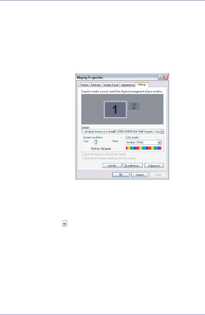
1. You cannot move from the [Settings] tab of [Display Properties] to the
multi-monitor when you are using the display of the computer and an
external CRT display or a TV at the same time.
*The [Settings] tab is displayed in the following steps;
1) Open [Control Panel], click [Appearance and Themes].
2) Click [display].
3) Select [Settings] tab.
Figure B-1 Display Properties (1)
■The way to move to multi-monitor
1) Press CTRL + ALT + F12 keys to make.
[Intel(R) 82852/82855 GM/GME Graphics Controller Prope...]
displayed (See Figure B-2).
2) Click in the left of [Devices] tab (See Figure B-2), then select
[Extended Desktop].
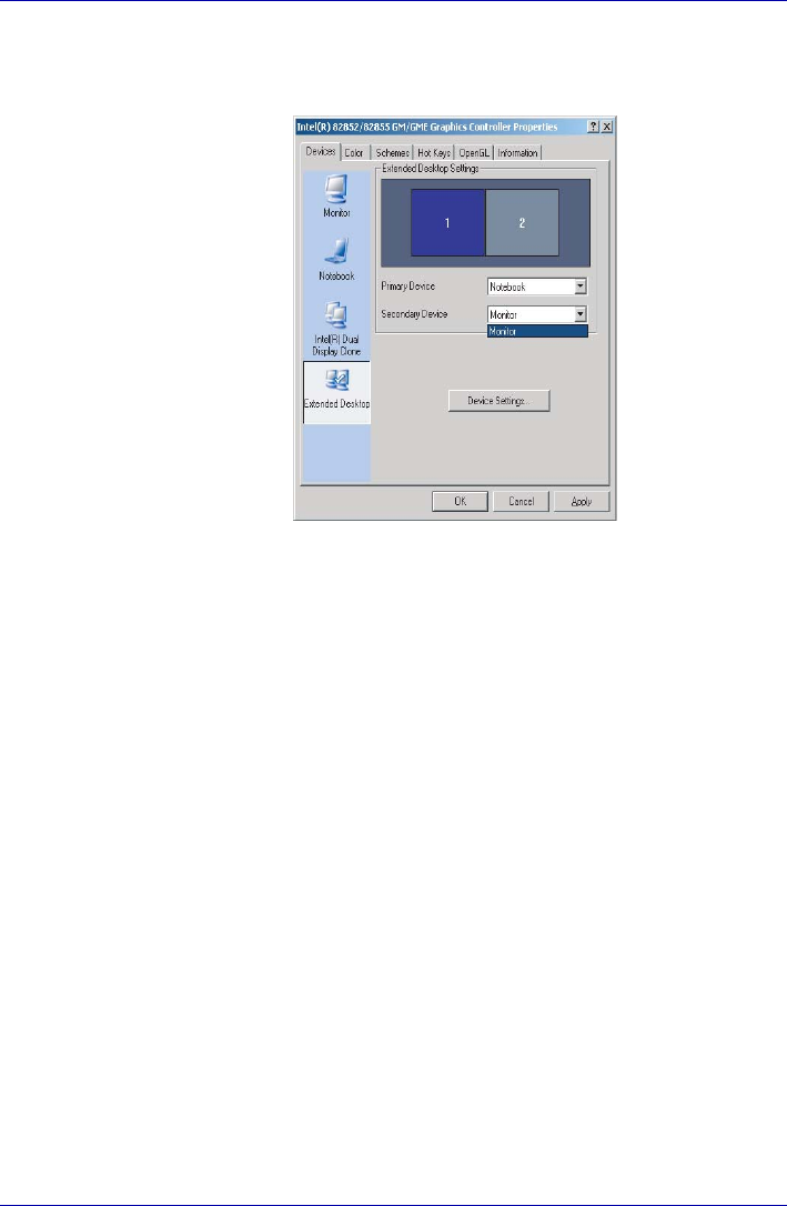
B-8 User’s Manual
Display Controller and Modes
3) Select the Monitor (CRT display), then select Apply button, because
the Primary Device is fixed into Notebook (the display of the
computer).
Figure B-2 Intel(R) 82852/82855 GM/GME Graphics Controller Prope...(1)
2. Some reproduced DVD picture may not be displayed when the display
of the computer and a CRT display are used at the same. Reduce the
resolution, use the display of the computer only, use the CRT display
only or set display device in the multi-monitor, then play DVD.
Please refer to External monitor in this manual of Chapter8 Optional
Devices or the application guide for the setting of each display device.
3. When playback DVD title with Multiple Monitors mode, there are some
case that DVD Overlay is not shown. In this case, please try to playback
WinDVD with decreasing resolution, refresh rate or color depth after
exit WinDVD player.
4. There are some case that you can select non-support mode with LCD/
CRT Dual Clone mode or MultiMonitor mode. In this case, please try to
decrease CRT resolution, refresh rate or color depth.

User’s Manual C-1
libretto U100
Appendix C
AT Commands
In most cases, you will not need to type AT commands manually. However,
there might be some occasions when you will need to do so.
This chapter describes AT commands for data mode. Fax and voice
commands are taken care of by application software.
The format for entering AT commands is:
ATXn
where X is the AT command, and n is the specific value for that command.
After you type in the command press ENTER.
Any command issued is acknowledged with a response in either text or
numeric values known as result codes.
All commands and command-values accepted by the modem are
described in this section; any entry other than those listed results in an
error.
+++ Escape sequence
The escape sequence allows the modem to exit data mode and enter on-
line command mode. While in on-line command mode, you can
communicate directly to your modem using AT commands. Once you
finish, you can return to data mode using the ATO command.
A pause, the length of which is set by Escape Guard Time (S12), must be
completed after an escape sequence is entered. This pause prevents the
modem from interpreting the escape sequence as data.
The value of the escape sequence character may be changed using
register S2.
A/ Repeat last command
This command repeats the last command string entered. Do not precede
this command with an AT prefix or conclude it by pressing Enter.
A Answer command
This command instructs the modem to go off-hook and answer an incoming
call.

C-2 User’s Manual
AT Commands
Bn Communication standard setting
This command determines the communication standard CCITT or Bell.
B0 Selects CCITT V.22 mode when the modem is at 1200 bps.
B1 Selects Bell 212A when the modem is at 1200 bps (default).
B15 Selects V.21 when the modem is at 300 bps.
B16 Selects Bell 103J when the modem is at 300 bps (default).
Result Codes:
OK n=0,1,15,16
ERROR Otherwise
Dn Dial
This command instructs the modem to dial a telephone number. Enter n
(the telephone number and any modifiers) after the ATD command.
Any digit or symbol (0-9, *, #, A, B, C, D) may be dialed as touch-tone
digits. Characters such as spaces, hyphens, and parentheses do not count.
They are ignored by the modem, but you may want to include them to make
the number and modifiers easier to read.
The following may be used as phone number modifiers:
PPulse dialing.
TTouch-tone dialing (default).
,Pause during dialing. Pause for time specified in Register S8
before processing the next character in the dial string.
WWait for dial tone. Modem waits for a second dial tone before
processing the dial string.
@Wait for quiet answer. Wait for five seconds of silence after
dialing the number. If silence is not detected, the modem
sends a NO ANSWER result code back to the caller.
!Hook flash. Causes the modem to go on-hook for 0.5
seconds and then return to off-hook.
;Return to command mode. Causes the modem to return to
command mode after dialing a number, without
disconnecting the call.
S=n Dial a telephone number previously stored using the &Zn=X
command (See &Zn=X command for more information). The
range is 0-3.
En Echo command
This command controls whether or not the characters entered from your
computer keyboard are displayed on your monitor (echoed) while the
modem is in command mode.
E0 Disables echo to the computer.
E1 Enables echo to the computer (default).

User’s Manual C-3
AT Commands
Result Codes:
OK n=0,1
ERROR Otherwise
Hn Hook control
This command instructs the modem to go on-hook to disconnect a call, or
off-hook to make the phone line busy.
H0 Modem goes on-hook (default).
H1 Modem goes off-hook.
Result Codes:
OK n=0,1
ERROR Otherwise
In Request ID information
This command displays product information about the modem.
I0 Returns modem identity string and driver version number.
I3 Same as I0.
I9 Returns region ID in English.
Result Codes:
OK n=0,3,9
ERROR Otherwise
Ln Monitor speaker volume
This command sets speaker volume to low, medium, or high.
L0 Low volume.
L1 Low volume. (Same as L0)
L2 Medium volume (default).
L3 High volume.
Result Codes:
OK n=0,1,2,3
ERROR Otherwise
Mn Monitor speaker mode
This command turns the speaker on or off.
M0 The speaker is off.
M1 The speaker is on until the modem detects the carrier signal
(default).
M2 The speaker is always on when modem is off-hook.
M3 Speaker is on until the carrier is detected, except when
dialing.
Result Codes:
OK n=0,1,2,3
ERROR Otherwise

C-4 User’s Manual
AT Commands
Nn Modulation handshake
This command controls whether or not the local modem performs a
negotiated handshake at connection time with the remote modem when the
communication speed of the two modems is different.
N0 When originating or answering, this is for handshake only at
the communication standard specified by S37 and the ATB
command.
N1 When originating or answering, begin the handshake at the
communication standard specified by S37 and the ATB
command (default).
During handshake, a lower transmission speed may be
selected.
Result Codes:
OK n=0,1
ERROR Otherwise
On Return on-line to data mode
O0 Instructs the modem to exit on-line command mode and
return to data mode (see AT escape sequence, +++).
O1 This command issues a retrain before returning to on-line
data mode.
O3 This command issues a rate renegotiation before returning to
on-line data mode.
Result Codes:
OK n=0,1,3
ERROR Otherwise
P Select pulse dialing
This command configures the modem for pulse (non touch-tone) dialing.
Dialed digits are pulsed until a T command or dial modifier is received.
Tone dial is the default setting.
Qn Result code control
Result codes are informational messages sent from the modem and
displayed on your monitor. Basic result codes are OK, CONNECT, RING,
NO CARRIER, and ERROR. The ATQ command allows the user to turn
result codes on or off.
Q0 Enables modem to send result codes to the computer
(default).
Q1 Disables modem from sending result codes to the computer.
Result Codes:
OK n=0,1
ERROR Otherwise

User’s Manual C-5
AT Commands
T Select tone dialing
This command instructs the modem to send DTMF tones while dialing.
Dialed digits are tone dialed until a P command or dial modifier is received.
This is the default setting.
Vn DCE response format
This command controls whether result codes (including call progress and
negotiation progress messages) are displayed as words or their numeric
equivalents.
V0 Displays result codes as digits.
V1 Displays result codes as text (default).
Result Codes:
OK n=0,1
ERROR Otherwise
Xn Result code selection, call progress monitoring
This command selects which result codes will be used by the modem.
Command Dial tone
detect
Busy
signal
detect
Supported Result Code
X0 Disable Disable OK, CONNECT, RING, NO CARRIER,
ERROR
X1 Disable Disable OK, RING, NO CARRIER, ERROR,
CONNECT <RATE>
X2 Enable Disable OK, RING, NO CARRIER, ERROR,
NODIALTONE, CONNECT <RATE>
X3 Disable Enable OK, RING, NO CARRIER, ERROR, BUSY,
CONNECT <RATE>, BLACKLISTED
X4 (default) Enable Enable OK, RING, NO CARRIER, ERROR,
NODIALTONE, BUSY, CONNECT <RATE>,
DELAYED, BLACKLISTED, REORDER,
WARBLE, CALL WAITING DETECTED
X5 Enable Enable OK, RING, NO CARRIER, ERROR,
NODIALTONE, BUSY, CONNECT <RATE>,
RRING, NO BONGTONE, DELAYED,
BLACKLISTED, REORDER, WARBLE, CALL
WAITING DETECTED

C-6 User’s Manual
AT Commands
Dial tone detect
Disabled: The modem dials a call regardless of whether it detects a dial
tone.
Enabled: The modem dials only upon detection of a dial tone, and
disconnects the call if the dial tone is not detected within 10
seconds.
Busy tone detect
Disabled: The modem ignores any busy tones it receives.
Enabled: The modem monitors for busy tones.
Result Codes:
OK n=0,1,2,3,4,5
ERROR Otherwise
Zn Recall stored profile
The modem performs a soft reset and restores (recalls) the configuration
profile according to the parameter supplied. If no parameter is specified,
zero is assumed. Either Z0 or Z1 restores the profile.
Result Codes:
OK n=0,1
ERROR Otherwise
&Cn Data Carrier Detect (DCD) control
Data Carrier Detect is a signal from the modem to the computer indicating
that a carrier signal is being received from a remote modem. DCD normally
turns off when the modem no longer detects the carrier signal.
&C0 The state of the carrier from the remote modem is ignored.
DCD circuit is always on.
&C1 DCD turns on when the remote modem’s carrier signal is
detected, and off when the carrier signal is not detected
(default).
Result Codes:
OK n=0,1
ERROR Otherwise
&Dn DTR control
This command interprets how the modem responds to the state of the DTR
signal and changes to the DTR signal.
&D0 Ignore. The modem ignores the true status of DTR and treats
it as always on. This should only be used if your
communication software does not provide DTR to the
modem
&D1 If the DTR signal is not detected while in on-line data mode,
the modem enters command mode, issues an OK result
code, and remains connected.

User’s Manual C-7
AT Commands
&D2 If the DTR signal is not detected while in on-line data mode,
the modem disconnects (default).
&D3 Reset on the on-to-off DTR transition.
Result Codes:
OK n=0,1,2,3
ERROR Otherwise
&F Load factory settings
This command loads the configuration stored and programmed at the
factory. This operation replaces all of the command options and the S-
register settings in the active configuration with factory values.
&F Recall factory setting as active configuration.
&Gn V.22bis guard tone control
This command determines which guard tone, if any, to transmit while
transmitting in the high band (answer mode). This command is only used in
V.22 and V.22bis mode. This option is not used in North America and is for
international use only.
&G0 Guard tone disabled (default).
&G1 Sets guard tone to 550 Hz.
&G2 Sets guard tone to 1800 Hz.
Result Codes:
OK n=0,1,2
ERROR Otherwise
&Kn Local flow control selection
&K0 Disable flow control.
&K3 Enable CTS/RTS flow control (default).
&K4 Enable XON/XOFF flow control.
Result Codes:
OK n=0,3,4
ERROR Otherwise
&Pn Select Pulse Dial Make/Break Ratio (WW)
&P0 Selects 39% - 61% make/break ratio at 10 pulses per
second.
&P1 Selects 33% - 67% make/break ratio at 10 pulses per
second.
&P2 Selects 33% - 67% make/break ratio at 20 pulses per
second.
Result Codes:
OK n=0,1,2
ERROR Otherwise

C-8 User’s Manual
AT Commands
&Tn Self-test commands
These tests can help to isolate problems if you experience periodic data
loss or random errors.
&T0 Abort. Stops any test in progress.
&T1 Local analog loop. This test verifies modem operation, as
well as the connection between the modem and computer.
Any data entered at the local DTE is modulated, then
demodulated, and returned to the local DTE. To work
properly, the modem must be off-line.
Result Codes:
OK n=0
CONNECT n=1
ERROR Otherwise
&V Display Current Configuration
This command displays the current configuration of the modem. If
nonvolatile memory is supported the stored profiles are displayed as well.
&V View profiles.
&W Store current configuration
Saves the current (active) configuration (profile), including S-Registers.
The current configuration comprises a list of storable parameters illustrated
in the &V command. These settings are restored to the active configuration
upon receiving a Zn command or at power up. Refer to the &V command.
&W Stores the current configuration.
&Zn=x Store telephone number
This command is used to store up to four dialing strings in the modem’s
nonvolatile memory for later dialing. The format for the command is
&Zn=“stored number” where n is the location 0-3 to which the number
should be written. The dial string may contain up to 34 characters. The
ATDS=n command dials using the string stored in location n.
Result Codes:
OK n=0, 1, 2, 3
ERROR Otherwise
\Nn Error control mode selection
This command determines the type of error control used by the modem
when sending or receiving data.
\N0 Buffer mode. No error control.
\N1 Direct mode.
\N2 MNP or disconnect mode. The modem attempts to connect
using MNP2-4 error control procedures. If this fails, the
modem disconnects.
This is also known as MNP reliable mode.

User’s Manual C-9
AT Commands
\N3 V.42, MNP, or buffered (default).
The modem attempts to connect in V.42 error control mode.
If this fails, it attempts to connect in MNP mode. If this fails, it
connects in buffer mode and continues operation. This is
also known as V.42/MNP auto reliable mode (same as &Q5).
\N4 V.42 or disconnect. The modem attempts to connect in V.42
error control mode. If this fails, the modem disconnects.
\N5 V.42. MNP or buffered (same as \N3).
\N7 V.42. MNP or buffered (same as \N3).
Result Codes:
OK n=0,1,2,3,4,5,7
ERROR Otherwise
\Qn Local flow control selection
\Q0 Disable flow control.
\Q1 XON/XOFF software flow control.
\Q3 CTS/RTS to DTE (default).
Result Codes:
OK n=0,1,3
ERROR Otherwise
\Vn Protocol result code
\V0 Disable protocol result code appended to DCE speed.
\V1 Enable protocol result code appended to DCE speed
(default).
Result Codes:
OK n=0,1
ERROR Otherwise
%B View numbers in blacklist
If blacklisting is in effect, this command displays the numbers for which the
last call attempted in the past two hours failed. The ERROR result code
appears in regions that do not require blacklisting.
%Cn Data compression control
This command determines the operation of V.42bis and MNP class 5 data
compression. On-line changes do not take effect until a disconnect occurs
first.
%C0 V.42bis/MNP 5 disabled. No data compression.
%C3 V.42bis/MNP 5 enabled. Data compression enabled
(default).

C-10 User’s Manual
AT Commands
Result Codes:
OK n=0,3
ERROR Otherwise

User’s Manual D-1
libretto U100
Appendix D
S-registers
S-registers contain the settings that determine how a number of functions
of the internal modem operate. For example, how many times to let the
telephone ring before the modem answers and how long to wait before it
hangs up if a connection fails. You can also customize certain AT
commands such as the escape sequence and command line termination.
The contents of the registers are changed automatically when you modify
corresponding settings in your communication software. If you choose,
however, you can display and edit the contents of the registers manually
when the modem is in command mode. If the value is out of the acceptable
range, then an error is generated.
This chapter describes the settings for each S-register.
S-register values
The format for displaying the value of an S-register is:
ATSn?
where n is the register number. After you type in the register press ENTER.
The format for modifying the value of an S-register is:
ATSn=r
where n is the register number, and r is the new register value. After you
type in the register and its new value press ENTER.
S0 Auto answer ring number
This register determines the number of rings the modem will count
before automatically answering a call. Enter 0 (zero) if you do not
want the modem to automatically answer at all. When disabled,
the modem can only answer with an ATA command.
Range: 0-255
Default: 0
Units: rings
Some registers vary from one country/region to another.

D-2 User’s Manual
S-registers
S1 Ring counter
This register is read only. The value of S1 is incremented with
each ring. If no ring occurs over a six-second interval, this register
is cleared.
Range: 0-225
Default: 0
Units: rings
S2 AT escape character (user defined)
This register determines the ASCII values used for an escape
sequence. The default is the + character. The escape sequence
allows the modem to exit data mode and enter command mode
when on-line. Values greater than 127 disable the escape
sequence.
Range: 0-255, ASCII decimal
Default: 43
Units: ASCII
S3 Command line termination character (user defined)
This register determines the ASCII values as the carriage return
character. This character is used to end command lines and result
codes.
Range: 0-127, ASCII decimal
Default: 13 (carriage return)
Units: ASCII
S4 Response formatting character (user defined)
This register determines the ASCII value used as the line feed
character. The modem uses a line feed character in command
mode when it responds to the computer.
Range: 0-127, ASCII decimal
Default: 10 (line feed)
Units: ASCII

User’s Manual D-3
S-registers
S5 Command line editing character (user defined)
This register sets the character recognized as a backspace and
pertains to asynchronous only. The modem will not recognize the
backspace character if it is set to a value that is greater than 32
ASCII. This character can be used to edit a command line. When
the echo command is enabled, the modem echoes back to the
local DTE the backspace character, an ASCII space character,
and a second backspace character. This means a total of three
characters are transmitted each time the modem processes the
backspace character.
Range: 0-127, ASCII decimal
Default: 8 (backspace)
Units: ASCII
S6 Wait before dialing
This register sets the length of time, in seconds, that the modem
must wait (pause) after going off-hook before dialing the first digit
of the telephone number. The modem always pauses for a
minimum of two seconds, even if the value of S6 is less that two
seconds. The wait for dial tone call progress feature (W dial
modifier in the dial string) will override the value in register S6.
This operation, however, may be affected by some ATX options
according to country/region restrictions. In some countries/regions,
S6 will set dial tone detect time.
Range: 3-255
Default: 3
Units: seconds
S7 Connection completion time-out
This register sets the time, in seconds, that the modem must wait
before hanging up because carrier is not detected. The timer is
started when the modem finishes dialing (originate), or goes off-
hook (answer). In originate mode, the timer is reset upon detection
of an answer tone if allowed by county restriction. The timer also
specifies the wait for silence time for the @ dial modifier in
seconds. S7 is not associated with the W dial modifier.
Range: 1-255
Default: 50
Units: seconds

D-4 User’s Manual
S-registers
S8 Comma pause time
This register sets the time, in seconds, that the modem must
pause when it encounters a comma (,) in the dial command string.
In some countries/regions, S8 will set both wait before dialing and
comma pause time.
Range: 0-255
Default: 2
Units: seconds
S11 DTMF dialing speed
This register determines the dialing speed which is prefixed for
each country/region.
Range: 50-255
Default: 95
Units: .001 seconds
S12 Escape guard time
This register sets the value (in 20 millisecond increments) for the
required pause after the escape sequence.
Range: 0-255
Default: 50
Units: .02 seconds

User’s Manual D-5
S-registers
S37 Dial line rate
S37 = 0 (default) maximum modem speed
S37 = 1 reserved
S37 = 2 1200/75 bps
S37 = 3 300 bps
S37 = 4 reserved
S37 = 5 1200 bps
S37 = 6 2400 bps
S37 = 7 4800 bps
S37 = 8 7200 bps
S37 = 9 9600 bps
S37 = 10 12000 bps
S37 = 11 14400 bps
S37 = 12 16800 bps
S37 = 13 19200 bps
S37 = 14 21600 bps
S37 = 15 24000 bps
S37 = 16 26400 bps
S37 = 17 28800 bps
S37 = 18 31200 bps
S37 = 19 33600 bps

D-6 User’s Manual
S-registers
AT command set result codes
The following table shows the result codes.
The result code summary
Result Code Numeric Description
OK 0 Command executed
CONNECT 1 Modem connected to line
RING 2 A ring signal has been
detected
NO CARRIER 3 Modem lost carrier signal, or
does not detect carrier
signal, or does not detect
answer tone
ERROR 4 Invalid command
CONNECT 1200 EC*15 Connection at 1200 bps
NO DIAL TONE 6 No dial tone detected
BUSY 7 Busy signal detected
NO ANSWER 8 No quiet answer
CONNECT 2400 EC*110 Connection at 2400 bps
CONNECT 4800 EC*111 Connection at 4800 bps
CONNECT 9600 EC*112 Connection at 9600 bps
CONNECT 14400 EC*113 Connection at 14400 bps
CONNECT 19200 EC*114 Connection at 19200 bps
CONNECT 7200 EC*124 Connection at 7200 bps
CONNECT 12000 EC*125 Connection at 12000 bps
CONNECT 16800 EC*186 Connection at 16800 bps
CONNECT 300 EC*140 Connection at 300 bps
CONNECT 21600 EC*155 Connection at 21600 bps
CONNECT 24000 EC*156 Connection at 24000 bps
CONNECT 26400 EC*157 Connection at 26400 bps
CONNECT 28800 EC*158 Connection at 28800 bps
CONNECT 31200 EC*159 Connection at 31200 bps

User’s Manual D-7
S-registers
*1: EC only appears when the Extended Result Codes configuration option
is enabled. EC is replaced by one of the following symbols, depending
upon the error control method used:
V.42bis - V.42 error control and V.42bis data compression.
V.42 - V.42 error control only.
MNP 5 - MNP class 4 error control and MNP class 5 data
compression.
MNP 4 - MNP class 4 error control only.
NoEC - No error control protocol.
*2: In some countries/regions, these result codes may not appear.
CONNECT 33600 EC*160 Connection at 33600 bps
DELAYED*288 Delay is in effect for the
dialed number
BLACKLISTED*289 Dialed number is blacklisted
BLACKLIST FULL*290 Blacklist is full

D-8 User’s Manual
S-registers

User’s Manual E-1
libretto U100
Appendix E
V.90
The TOSHIBA internal modem uses V.90 technology. The modem is
capable of downstream speeds of 56kbps (kilobits per second) when
connected to an Internet service provider that supports V.90. As with any
modem, the actual throughput (speed of data transfer) depends on analog
telephone line conditions, which can vary considerably. Therefore, many
users will experience throughput in the range of 28-50kbps under normal
telephone line conditions. Upstream data flows at the V.34 rate.
V.90 mode
V.90 rates can be achieved only when one V.90-capable host modem is
connected to another. The TOSHIBA Internal modem will select
automatically V.34 if the remote modem lacks V.90 capability or if a
combination of network and/or phone line conditions prevent V.90
connection.
Function Transmission speed
Data V.90 From 56kbps (maximum) to 28kbps
(minimum)
Reception only

E-2 User’s Manual
V.90
Table E-1 Result codes for a V.90 connection
No. Result code Description
70 CONNECT 32000 EC* Connection at 32000 bps
72 CONNECT 36000 EC* Connection at 36000 bps
74 CONNECT 40000 EC* Connection at 40000 bps
76 CONNECT 44000 EC* Connection at 44000 bps
78 CONNECT 48000 EC* Connection at 48000 bps
80 CONNECT 52000 EC* Connection at 52000 bps
82 CONNECT 56000 EC* Connection at 56000 bps
100 CONNECT 28000 EC* Connection at 28000 bps
101 CONNECT 29333 EC* Connection at 29333 bps
102 CONNECT 30666 EC* Connection at 30666 bps
103 CONNECT 33333 EC* Connection at 33333 bps
104 CONNECT 34666 EC* Connection at 34666 bps
105 CONNECT 37333 EC* Connection at 37333 bps
106 CONNECT 38666 EC* Connection at 38666 bps
107 CONNECT 41333 EC* Connection at 41333 bps
108 CONNECT 42666 EC* Connection at 42666 bps
109 CONNECT 45333 EC* Connection at 45333 bps
110 CONNECT 46666 EC* Connection at 46666 bps
111 CONNECT 49333 EC* Connection at 49333 bps
112 CONNECT 50666 EC* Connection at 50666 bps
113 CONNECT 53333 EC* Connection at 53333 bps
114 CONNECT 54666 EC* Connection at 54666 bps

User’s Manual E-3
V.90
* EC stands for the Error Control method, which appears only when the
extended result codes configuration option is enabled. EC is replaced by
one of the following symbols, depending on the error control method
used.
AT Command
V42bis V.42 error control and V.42bis data compression
V42 V.42 error control only
NoEC No error control protocol
-V90=* V.90 Dial Line Rate
-V90 sets the maximum V.90 downstream that the
modem attempts to connect.
-V90=0 V.90 disabled
-V90=1 V.90 enabled: automatic speed selection -
maximum modem speed (default)

E-4 User’s Manual
V.90

User’s Manual F-1
libretto U100
Appendix F
Wireless LAN
Card Specifications
Form Factor Mini PCI Type III
Compatibility ■IEEE 802.11 Standard for Wireless LANS
■Wi-Fi (Wireless Fidelity) certified by the Wi-Fi
Alliance. The ‘Wi-Fi CERTIFIED’ logo is a
certification mark of the Wi-Fi Alliance.
Network Operating
System
■Microsoft Windows® Networking
Media Access
Protocol
■CSMA/CA (Collision Avoidance) with
Acknowledgment (ACK)
Data Rate ■ Theoretical maximum speed: 54Mbps (IEEE802.11a/g)
■Theoretical maximum speed: 11Mbps (IEEE802.11b)

F-2 User’s Manual
Wireless LAN
Radio Characteristics
Radio Characteristics of Wireless LAN Cards may vary according to:
■Country/region where the product was purchased
■Type of product
Wireless communication is often subject to local radio regulations.
Although Wireless LAN wireless networking products have been designed
for operation in the license-free 2.4GHz/5GHz band, local radio regulations may
impose a number of limitations to the use of wireless communication
equipment.
The range of the wireless signal is related to the transmit rate of the
wireless communication. Communications at lower transmit range may
travel larger distances.
■The range of your wireless devices can be affected when the antennas
are placed near metal surfaces and solid high-density materials.
■Range is also impacted due to "obstacles" in the signal path of the radio
that may either absorb or reflect the radio signal.
Supported Frequency Sub-bands
Subject to the radio regulations that apply in the countries/regions, your
Wireless LAN card may support a different set of 2.4 GHz/5GHz channels.
Consult your Authorized Wireless LAN or TOSHIBA Sales office for
information about the radio regulations that apply in the countries/regions.
Refer to the sheet “Information to the User” for regulatory information that
may apply in your country/region.
R-F Frequency Band 2.4GHz (2400-2483.5 MHz) (Revision B,
G) Band 5GHz (5150-5850MHz)(Revision A)
Modulation
Technique
■DSSS-CCK, DSSS-DQPSK, DSSS-DBPSK
(Revision B)
■OFDM-BPSK, OFDM-QPSK, OFDM-16QAM,
OFDM-64QAM (Revision A,G)

User’s Manual F-3
Wireless LAN
Wireless IEEE 802.11 Channels Sets (Revision B and G)
*1 Factory-set default channels
*2 Refer to the sheet Approved Countries/Regions for use for the countries/
regions that in which these channels can be used.
When installing Wireless LAN cards, the channel configuration is managed
as follows:
■For wireless clients that operate in a Wireless LAN Infrastructure, the
Wireless LAN card will automatically start operation at the channel
identified by the Wireless LAN Access Point. When roaming between
different access points the station can dynamically switch to another
channel if required.
■For Wireless LAN cards installed in wireless clients that operating in a
peer-to-peer mode, the card will use the default channel 10.
■In a Wireless LAN Access Point, the Wireless LAN card will use the
factory-set default channel (printed in bold), unless the LAN
Administrator selected a different channel when configuring the
Wireless LAN Access Point device.
Frequency Range
Channel ID*2 2400-2483.5 MHz
12412
22417
32422
42427
52432
62437
72442
82447
92452
10 2457*1
11 2462
12 2467
13 2472
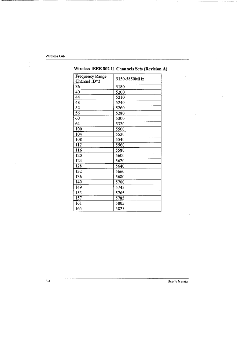

User’s Manual G-1
libretto U100
Appendix G
AC Power Cord and Connectors
The power cord’s AC input plug must be compatible with the various
international AC power outlets and the cord must meet the standards for
the country/region in which it is used. All cords must meet the following
specifications:
Certification agencies
Length: Minimum 2 meters
Wire size: Minimum 0.75 mm2
Current rating: Minimum 2.5 amperes
Voltage rating: 125 or 250 VAC
(depending on country/region’s power standards)
U.S. and Canada: UL listed and CSA certified
No. 18 AWG, Type SVT or SPT-2
Australia: AS
Japan: DENANHO
Europe:
Austria: OVE Italy: IMQ
Belgium: CEBEC The Netherlands: KEMA
Denmark: DEMKO Norway: NEMKO
Finland: FIMKO Sweden: SEMKO
G-2 User’s Manual
AC Power Cord and Connectors
In Europe, two conductors power cord must be VDE type, H05VVH2-F or
H03VVH2-F and for three conductors power cord must be VDE type,
H05VV-F.
For the United States and Canada, two pin plug configuration must be a 2-
15P (250V) or 1-15P (125V) and three pin plug configuration must be 6-
15P (250V) or 5-15P (125V) as designated in the U.S. National Electrical
code handbook and the Canadian Electrical Code Part II.
The following illustrations show the plug shapes for the U.S.A. and Canada,
the United Kingdom, Australia and Europe.
France: LCIE Switzerland: SEV
Germany: VDE United Kingdom: BSI
USA
Australia Europe
United Kingdom
AS approved Approved by the
BS approved
UL approved
CSA approved
appropriate agency
Canada

User’s Manual H-1
libretto U100
Appendix H
Parts Numbers
The computer configuration and parts numbers, printed on a label on the
bottom of the computer, indicate the CPU, Memory, External VRAM, HDD,
ODD.BAY, Wireless LAN/BT, OS and Warranty.
Configurations
CPU Memory External VRAM
Pentium M 753 (1.2GHz ULV) PM753 256MB 256 None
Pentium M 733 (1.1GHz ULV) PM733 512MB 512
1024MB 1024
HDD (Primary, 2nd/bay) ODD. Bay WirelessLAN / BT
30GB 30 None 802.11g / No BT g
60GB 60 9.5mm CD-RW/DVD-ROM RDV 802.11g / BT gBT
9.5mm DVD-SuperMulti DM

H-2 User’s Manual
Parts Numbers

User’s Manual Glossary-1
libretto U100
Glossary
The terms in this glossary cover topics related to this manual.
Alternate naming is included for reference.
Abbreviations
AC: alternating current
AGP: accelerated graphics port
ANSI: American National Standards Institute
APM: advanced power manager
ASCII: American Standard Code for Information Interchange
BIOS: basic input output system
CD-ROM: Compact Disc-Read Only Memory
CD-RW: Compact Disc-ReWritable
CMOS: complementary metal-oxide semiconductor
CPU: central processing unit
CRT: cathode ray tube
DC: direct current
DDC: display data channel
DMA: direct memory access
DOS: disk operating system
DVD: digital versatile disc
DVD-R: Digital Versatile Disc-Recordable
DVD-RAM: Digital Versatile Disc-Random Access Memory
DVD-ROM: Digital Versatile Disc-Read Only Memory
DVD-RW: Digital Versatile Disc-ReWritable
ECP: extended capabilities port
FDD: floppy disk drive
FIR: fast infrared
HDD: hard disk drive
IDE: integrated drive electronics
I/O: input/output

Glossary-2 User’s Manual
Glossary
IrDA: Infrared Data Association
IRQ: interrupt request
KB: kilobyte
LCD: liquid crystal display
LED: light emitting diode
LSI: large scale integration
MB: megabyte
MS-DOS: Microsoft Disk Operating System
OCR: optical character recognition (reader)
PCB: printed circuit board
PCI: peripheral component interconnect
RAM: random access memory
RGB: red, green, and blue
ROM: read only memory
RTC: real time clock
SCSI: small computer system interface
SIO: serial input/output
SXGA+: super extended graphics array plus
TFT: thin-film transistor
UART: universal asynchronous receiver/transmitter
USB: Universal Serial Bus
UXGA: ultra extended graphics array
VESA: Video Electronic Standards Association
VGA: video graphics array
VRT: voltage reduction technology
WXGA: wide extended graphics array
XGA: extended graphics array
A
AccuPoint: A pointing device integrated into the TOSHIBA computer
keyboard.
adaptor: A device that provides an interface between two dissimilar
electronic devices. For example, the AC adaptor modifies the power
from a wall outlet for use by the computer. This term also refers to
the add-in circuit cards that control external devices, such as video
monitors and magnetic tape devices.
allocate: To assign a space or function for a specific task.
alphanumeric: Keyboard characters including letters, numbers and other
symbols, such as punctuation marks or mathematical symbols.
alternating current (AC): Electric current that reverses its direction of flow
at regular intervals.

User’s Manual Glossary-3
Glossary
analog signal: A signal whose characteristics such as amplitude and
frequency vary in proportion to (are an analog of) the value to be
transmitted. Voice communications are analog signals.
ANSI: American National Standards Institute. An organization established
to adopt and define standards for a variety of technical disciplines.
For example, ANSI defined the ASCII standard and other
information processing requirements.
antistatic: A material used to prevent the buildup of static electricity.
application: A group of programs that together are used for a specific task
such as accounting, financial planning, spreadsheets, word
processing and games.
ASCII: American Standard Code for Information Interchange. ASCII code
is a set of 256 binary codes that represent the most commonly used
letters, numbers, and symbols.
async: Short for asynchronous.
asynchronous: Lacking regular time relationship. As applied to computer
communications, asynchronous refers to the method of transmitting
data that does not require a steady stream of bits to be transmitted
at regular time intervals.
B
backup: A duplicate copy of files kept as a spare in case the original is
destroyed.
batch file: A file that can be executed from the system prompt containing
a sequence of operating system commands or executable files.
binary: The base two number system composed of zeros and ones (off or
on), used by most digital computers. The right-most digit of a binary
number has a value of 1, the next a value of 2, then 4, 8, 16, and so
on. For example, the binary number 101 has a value of 5. See also
ASCII.
BIOS: Basic Input Output System. The firmware that controls data flow
within the computer. See also firmware.
bit: Derived from "binary digit," the basic unit of information used by the
computer. It is either zero or one. Eight bits is one byte. See also
byte.
board: A circuit board. An internal card containing electronic components,
called chips, which perform a specific function or increase the
capabilities of the system.
boot: Short for bootstrap. A program that starts or restarts the computer.
The program reads instructions from a storage device into the
computer’s memory.
bps: Bits per second. Typically used to describe the data transmission
speed of a modem.
buffer: The portion of the computer’s memory where data is temporarily
stored. Buffers often compensate for differences in the rate of flow
from one device to another.

Glossary-4 User’s Manual
Glossary
bus: An interface for transmission of signals, data or electric power.
byte: The representation of a single character. A sequence of eight bits
treated as a single unit; also the smallest addressable unit within the
system.
C
cache memory: High speed memory which stores data that increases
processor speed and data transfer rate. When the CPU reads data
from main memory, it stores a copy of this data in cache memory.
The next time the CPU needs that same data, it looks for it in the
cache memory rather than the main memory, which saves time. The
computer has two cache levels. Level one is incorporated into the
processor and level two resides in external memory.
capacity: The amount of data that can be stored on a magnetic storage
device such as a floppy disk or hard disk. It is usually described in
terms of kilobytes (KB), where one KB = 1024 bytes and megabytes
(MB), where one MB = 1024 KB.
card: Synonym for board. See board.
CardBus: An industry standard bus for 32-bit PC cards.
CD-ROM: A Compact Disc-Read Only Memory is a high capacity disc that
can be read from but not written to. The CD-ROM drive uses a laser,
rather than magnetic heads, to read data from the disc.
CD-R: A Compact Disc-Recordable disc can be written once and read
many times. See also CD-ROM.
CD-RW: A Compact Disc-ReWritable disc can be rewritten many times.
See also CD-ROM.
character: Any letter, number, punctuation mark, or symbol used by the
computer. Also synonymous with byte.
chassis: The frame containing the computer.
chip: A small semiconductor containing computer logic and circuitry for
processing, memory, input/output functions and controlling other
chips.
CMOS: Complementary Metal-Oxide Semiconductor. An electronic circuit
fabricated on a silicon wafer that requires very little power.
Integrated circuits implemented in CMOS technology can be tightly
packaged and are highly reliable.
cold start: Starting a computer that is currently off (turning on the power).
COM1, COM2, COM3 and COM4: The names assigned to the serial and
communication ports.
commands: Instructions you enter at the terminal keyboard that direct the
actions of the computer or its peripheral devices.
communications: The means by which a computer transmits and
receives data to and from another computer or device. See parallel
interface; serial interface.

User’s Manual Glossary-5
Glossary
compatibility: 1) The ability of one computer to accept and process data
in the same manner as another computer without modifying the data
or the media upon which it is being transferred.
2) the ability of one device to connect to or communicate with
another system or component.
components: Elements or parts (of a system) which make up the whole
(system).
computer program: A set of instructions written for a computer that
enable it to achieve a desired result.
computer system: A combination of hardware, software, firmware, and
peripheral components assembled to process data into useful
information.
configuration: The specific components in your system (such as the
terminal, printer, and disk drives) and the settings that define how
your system works. You use the HW Setup program to control your
system configuration.
control keys: A key or sequence of keys you enter from the keyboard to
initiate a particular function within a program.
controller: Built-in hardware and software that controls the functions of a
specific internal or peripheral device (e.g. keyboard controller).
co-processor: A circuit built into the processor that is dedicated to
intensive math calculations.
CPS: Characters Per Second. Typically used to indicate the transmission
speed of a printer.
CPU: Central Processing Unit. The portion of the computer that interprets
and executes instructions.
CRT: Cathode Ray Tube. A vacuum tube in which beams projected on a
fluorescent screen-producing luminous spots. An example is the
television set.
cursor: A small, blinking rectangle or line that indicates the current
position on the display screen.
D
data: Information that is factual, measurable or statistical that a computer
can process, store, or retrieve.
data bits: A data communications parameter controlling the number of bits
(binary digits) used to make up a byte. If data bits = 7 the computer
can generate 128 unique characters. If data bits = 8 the computer
can generate 256 unique characters.
DC: Direct Current. Electric current that flows in one direction. This type of
power is usually supplied by batteries.
default: The parameter value automatically selected by the system when
you or the program do not provide instructions. Also called a preset
value.

Glossary-6 User’s Manual
Glossary
delete: To remove data from a disk or other data storage device.
Synonymous with erase.
device driver: A program that controls communication between a specific
peripheral device and the computer. The CONFIG.SYS file contains
device drivers that MS-DOS loads when you turn the computer on.
dialog box: A window that accepts user input to make system settings or
record other information.
disk drive: The device that randomly accesses information on a disk and
copies it to the computer’s memory. It also writes data from memory
to the disk. To accomplish these tasks, the unit physically rotates
the disk at high speed past a read-write head.
disk storage: Storing data on magnetic disk. Data is arranged on
concentric tracks much like a phonograph record.
display: A CRT, LCD, or other image producing device used to view
computer output.
documentation: The set of manuals and/or other instructions written for
the users of a computer system or application. Computer system
documentation typically includes procedural and tutorial information
as well as system functions.
DOS: Disk Operating System. See operating system.
driver: A software program, generally part of the operating system, that
controls a specific piece of hardware (frequently a peripheral device
such as a printer or mouse).
DVD-R (+R, -R): A Digital Versatile Disc-Recordable disk can be written
once and read many times. The DVD-R drive uses a laser to read
data from the disc.
DVD-RAM: A Digital Versatile Disc-Random Access Memory is a high-
capacity, high performance disc that lets you store large volumes of
data. The DVD-ROM drive uses a laser to read data from the disc.
DVD-ROM: A Digital Versatile Disc-Read Only Memory is a high capacity,
high performance disc suitable for play back of video and other
high-density files. The DVD-ROM drive uses a laser to read data
from the disc.
DVD-RW (+RW, -RW): A Digital Versatile Disc-ReWritable disc can be
rewritten many times.
E
echo: To send back a reflection of the transmitted data to the sending
device. You can display the information on the screen, or output it to
the printer, or both. When a computer receives back data it
transmitted to a CRT (or other peripheral device) and then
retransmits the data to printer, the printer is said to echo the CRT.
erase: See delete.

User’s Manual Glossary-7
Glossary
escape: 1) A code (ASCII code 27), signaling the computer that what
follows are commands; used with peripheral devices such as
printers and modems.
2) A means of aborting the task currently in progress.
escape guard time: A time before and after an escape code is sent to the
modem which distinguishes between escapes that are part of the
transmitted data, and escapes that are intended as a command to
the modem.
execute: To interpret and execute an instruction.
Extended Capability Port: An industry standard that provides a data
buffer, switchable forward and reverse data transmission, and run
length encoding (RLE) support.
F
fast infrared: An industry standard that enables cableless infrared serial
data transfer at speeds of up to 4 Mbps.
file: A collection of related information; a file can contain data, programs,
or both.
firmware: A set of instructions built into the hardware which controls and
directs a microprocessor’s activities.
floppy disk: A removable disk that stores magnetically encoded data.
floppy disk drive (FDD): An electromechanical device that reads and
writes to floppy disks.
Fn-esse: A TOSHIBA utility that lets you assign functions to hot keys.
folder: An icon in Windows used to store documents or other folders.
format: The process of readying a blank disk for its first use. Formatting
establishes the structure of the disk that the operating system
expects before it writes files or programs onto the disk.
function keys: The keys labeled F1 through F12 that tell the computer to
perform certain functions.
G
gigabyte (GB): A unit of data storage equal to 1024 megabytes. See also
megabyte.
graphics: Drawings, pictures, or other images, such as charts or graphs,
to present information.
H
hard disk: A non-removable disk usually referred to as drive C. The
factory installs this disk and only a trained engineer can remove it
for servicing. Also called fixed disk.
hard disk drive (HDD): An electromechanical device that reads and writes
a hard disk. See also hard disk.

Glossary-8 User’s Manual
Glossary
hardware: The physical electronic and mechanical components of a
computer system: typically, the computer itself, external disk drives,
etc. See also software and firmware.
hertz: A unit of wave frequency that equals one cycle per second.
hexadecimal: The base 16 numbering system composed of the digits 0
through 9 and the letters A, B, C, D, E, and F.
host computer: The computer that controls, regulates, and transmits
information to a device or another computer.
hot key: The computer’s feature in which certain keys in combination with
the extended function key, Fn, can be used to set system
parameters, such as speaker volume.
HW Setup: A TOSHIBA utility that lets you set the parameters for various
hardware components.
I
icon: A small graphic image displayed on the screen or in the indicator
panel. In Windows, an icon represents an object that the user can
manipulate.
i.LINK (IEEE1394): This port enables high-speed data transfer directly
from external devices such as digital video cameras.
infrared port: A cableless communications port capable of using infrared
signals to send serial data.
input: The data or instructions you provide to a computer, communication
device or other peripheral device from the keyboard or external or
internal storage devices. The data sent (or output) by the sending
computer is input for the receiving computer.
instruction: Statements or commands that specify how to perform a
particular task.
interface: 1) Hardware and/or software components of a system used
specifically to connect one system or device to another.
2) To physically connect one system or device to another to
exchange information.
3) The point of contact between user, the computer, and the
program, for example, the keyboard or a menu.
interrupt request: A signal that gives a component access to the
processor.
I/O: Input/output. Refers to acceptance and transfer of data to and from a
computer.
I/O devices: Equipment used to communicate with the computer and
transfer data to and from it.
IrDA 1.1: An industry standard that enables cableless infrared serial data
transfer at speeds of up to 4 Mbps.

User’s Manual Glossary-9
Glossary
J
jumper: A small clip or wire that allows you to change the hardware
characteristics by electrically connecting two points of a circuit.
K
K: Taken from the Greek word kilo, meaning 1000; often used as
equivalent to 1024, or 2 raised to the 10th power. See also byte and
kilobyte.
KB: See kilobyte.
keyboard: An input device containing switches that are activated by
manually pressing marked keys. Each keystroke activates a switch
that transmits a specific code to the computer. For each key, the
transmitted code is, in turn, representative of the (ASCII) character
marked on the key.
kilobyte (KB): A unit of data storage equal to 1024 bytes. See also byte
and megabyte.
L
level 2 cache: See cache.
Light Emitting Diode (LED): A semiconductor device that emits light
when a current is applied.
Liquid Crystal Display (LCD): Liquid crystal sealed between two sheets
of glass coated with transparent conducting material. The viewing-
side coating is etched into character forming segments with leads
that extend to the edge of the glass. Applying a voltage between the
glass sheets alters the brightness of the liquid crystal.
LSI: Large Scale Integration.
1) A technology that allows the inclusion of up to 100,000 simple
logic gates on a single chip.
2) An integrated circuit that uses large scale integration.
M
main board: See motherboard.
megabyte (MB): A unit of data storage equal to 1024 kilobytes. See also
kilobyte.
megahertz: A unit of wave frequency that equals 1 million cycles per
second. See also hertz.
menu: A software interface that displays a list of options on the screen.
Also called a screen.
microprocessor: A hardware component contained in a single integrated
circuit that carries out instructions. Also called the central
processing unit (CPU), one of the main parts of the computer.

Glossary-10 User’s Manual
Glossary
mode: A method of operation, for example, the boot mode, standby mode
or the hibernation mode.
modem: Derived from modulator/demodulator, a device that converts
(modulates) digital data for transmission over telephone lines and
then converts modulated data (demodulates) to digital format where
received.
monitor: A device that uses rows and columns of pixels to display
alphanumeric characters or graphic images. See also CRT.
motherboard: A name sometimes used to refer to the main printed circuit
board in processing equipment. It usually contains integrated
circuits that perform the processor’s basic functions and provides
connectors for adding other boards that perform special functions.
Sometimes called a main board.
MP3: An audio compression standard that enables high-quality
transmission and real-time playback of sound files.
N
non-system disk: A formatted floppy disk you can use to store programs
and data but you cannot use to start the computer. See system disk.
nonvolatile memory: Memory, usually read-only (ROM), that is capable
of permanently storing information. Turning the computer’s power
off does not alter data stored in nonvolatile memory.
numeric keypad overlay: A feature that allows you to use certain keys on
the keyboard to perform numeric entry, or to control cursor and
page movement.
O
OCR: Optical Character Recognition (reader). A technique or device that
uses laser or visible light to identify characters and input them into a
storage device.
online state: A functional state of a peripheral device when it is ready to
receive or transmit data.
operating system: A group of programs that controls the basic operation
of a computer. Operating system functions include interpreting
programs, creating data files, and controlling the transmission and
receipt (input/output) of data to and from memory and peripheral
devices.
output: The results of a computer operation. Output commonly indicates
data.
1) printed on paper, 2) displayed at a terminal, 3) sent through the
serial port of internal modem, or 4) stored on some magnetic media.

User’s Manual Glossary-11
Glossary
P
parallel interface: Refers to a type of information exchange that transmits
information one byte (8 bits) at a time. See also serial interface.
parity: 1) The symmetrical relationship between two parameter values
(integers) both of which are either on or off; odd or even; 0 or 1.
2) In serial communications, an error detection bit that is added to a
group of data bits making the sum of the bits even or odd. Parity can
be set to none, odd, or even.
password: A unique string of characters used to identify a specific user.
The computer provides various levels of password protection such
as user, supervisor and eject.
pel: The smallest area of the display that can be addressed by software.
Equal in size to a pixel or group of pixels. See pixel.
peripheral component interconnect: An industry standard 32-bit bus.
peripheral device: An I/O device that is external to the central processor
and/or main memory such as a printer or a mouse.
pixel: A picture element. The smallest dot that can be made on a display
or printer. Also called a pel.
plug and play: A capability with Windows that enables the system to
automatically recognize connections of external devices and make
the necessary configurations in the computer.
port: The electrical connection through which the computer sends and
receives data to and from devices or other computers.
Power Saver Utility: A TOSHIBA utility that lets you set the parameters
for various power-saving functions.
printed circuit board (PCB): A hardware component of a processor to
which integrated circuits and other components are attached. The
board itself is typically flat and rectangular, and constructed of
fiberglass, to form the attachment surface.
program: A set of instructions a computer can execute that enables it to
achieve a desired result. See also application.
prompt: A message the computer provides indicating it is ready for or
requires information or an action from you.
R
Radio frequency interference (RFI) shield: A metal shield enclosing the
printed circuit boards of the printer or computer to prevent radio and
TV interference. All computer equipment generates radio frequency
signals. The FCC regulates the amount of signals a computing
device can allow past its shielding. A Class A device is sufficient for
office use. Class B provides a more stringent classification for home
equipment use. TOSHIBA portable computers comply with Class B
computing device regulations.
Random Access Memory (RAM): High speed memory within the
computer circuitry that can be read or written to.

Glossary-12 User’s Manual
Glossary
restart: Resetting a computer without turning it off (also called “warm boot”
or “soft reset”). See also boot.
RGB: Red, green, and blue. A device that uses three input signals, each
activating an electron gun for a primary additive color (red, green,
and blue) or port for using such a device. See also CRT.
RJ11: A modular telephone jack.
RJ45: A modular LAN jack.
ROM: Read Only Memory: A nonvolatile memory chip manufactured to
contain information that controls the computer’s basic operation.
You cannot access or change information stored in ROM.
S
SCSI: Small Computer System Interface is an industry standard interface
for connection of a variety of peripheral devices.
SD card: Secure Digital cards are flash memory widely used in a variety of
digital devices such as digital cameras and Personal Digital
Assistants.
serial communications: A communications technique that uses as few as
two interconnecting wires to send bits one after another.
serial interface: Refers to a type of information exchange that transmits
information sequentially, one bit at a time. Contrast: Parallel
interface.
SIO: Serial Input/Output. The electronic methodology used in serial data
transmission.
soft key: Key combinations that emulate keys on the IBM keyboard,
change some configuration options, stop program execution, and
access the numeric keypad overlay.
software: The set of programs, procedures and related documentation
associated with a computer system. Specifically refers to computer
programs that direct and control the computer system’s activities.
See also hardware.
stop bit: One or more bits of a byte that follow the transmitted character or
group codes in asynchronous serial communications.
subpixel: Three elements, one red, one green and blue (RGB), that make
up a pixel on the color LCD. The computer sets subpixels
independently, each may emit a different degree of brightness. See
also pixel.
synchronous: Having a constant time interval between successive bits,
characters or events.
system disk: A disk that has been formatted with an operating system.
For MS-DOS the operating system is contained in two hidden files
and the COMMAND.COM file. You can boot a computer using a
system disk. Also called an operating system disk.

User’s Manual Glossary-13
Glossary
T
terminal: A typewriter-like keyboard and CRT display screen connected to
the computer for data input/output.
TFT display: A liquid crystal display (LCD) made from an array of liquid
crystal cells using active-matrix technology with thin film transistor
(TFT) to drive each cell.
TTL: Transistor-transistor logic. A logic circuit design that uses switching
transistors for gates and storage.
U
Universal Serial Bus: This serial interface lets you communicate with
several devices connected in a chain to a single port on the
computer.
V
VGA: Video Graphics Array is an industry standard video adaptor that lets
you run any popular software.
volatile memory: Random access memory (RAM) that stores information
as long as power is supplied to the computer.
W
warm start: Restarting or resetting a computer without turning it off.
window: A portion of the screen that can display its own application,
document or dialog box. Often used to mean a Microsoft Windows
window.
Wireless LAN: Local Area Network (LAN) through wireless
communication.
write protection: A method for protecting a floppy disk from accidental
erasure.

Glossary-14 User’s Manual
Glossary

User’s Manual Index-1
libretto U100
Index
A
AC adaptor 1-5
additional 1-16, 8-9
connecting 3-6
DC IN 15V jack 2-2
ASCII characters 5-8
B
Battery
charging 6-8
extending life 6-11
indicator 2-9, 6-2
monitoring capacity 6-9
real time clock 1-5, 6-4
safety precautions 6-5
save mode 1-12
types 6-3
Battery pack 1-4, 2-5
additional 8-9
replacing 6-11
Bluetooth 1-9, 4-34
problems 9-18
TOSHIBA Stack 1-14
Boot Priority 7-2
C
Cleaning the computer 4-38
Cooling vents 2-2
D
DC IN indicator 2-9, 6-3
Display 1-7, 2-8
automatic power off 1-11
brightness decrease 5-5
brightness increase 5-5
controller 1-7, B-1
hinge 2-8
opening 3-8
DLA for TOSHIBA 1-15, 4-22
Docking port 1-8, 2-6
Documentation list 1-3
DVD Super Multi drive 1-6
problems 9-10
using 4-10
writing 4-17
DVD-ROM&CD-R/RW drive 1-6
problems 9-9
using 4-10
writing 4-15
E
Environment 3-1
Equipment checklist 1-1
Equipment setup
general conditions 3-2
placement 3-3
Ergonomics
lighting 3-4
seating and posture 3-4
work habits 3-5
F
Fingerprint Sensor
problems 9-13
using 4-3
Floppy disk care 4-26

Index-2 User’s Manual
Index
FN + CTRL (enhanced key-
board simulation) 5-3
FN + ENTER (enhanced key-
board’s numeric keypad) 5-3
FN + ESC (sound mute) 5-4
FN + F1 (instant security) 5-4
FN + F10 (Arrow mode) 5-3
FN + F11 (Numeric mode) 5-3
FN + F12 (ScrLock) 5-3
FN + F2 (power save mode) 5-4
FN + F3 (Stand by) 5-4
FN + F4 (Hibernation) 5-4
FN + F5 (display selection) 5-5
FN + F6 (display brightness de-
crease) 5-5
FN + F7 (display brightness in-
crease) 5-5
FN + F8 (wireless setting) 5-5
FN + INS (change insertion/
overwrite) 5-3
FN + PGDN (move to next page)
5-3
FN + PGUP (move to last page)
5-3
FN + Space (LCD screen reso-
lution selection) 5-6
Fn-esse 1-13
Function keys 5-2
G
Graphics controller 1-7
H
Hard disk drive 1-5
automatic power off 1-11
HDD indicator 2-9
HDD Protection 4-39
Heat dispersal 1-12, 4-42
Hibernation 1-13, 5-4
Hot keys 1-11
display selection 5-5
instant security 5-4
Internal LCD screen bright-
ness decrease 5-5
Internal LCD screen bright-
ness increase 5-5
power save mode 5-4
sound mute 5-4
standby 5-4
wireless setting 5-5
HW Setup 1-13
accessing 7-1
boot priority 7-2
CPU 7-5
Device Config 7-6
display 7-2
general 7-2
keyboard 7-5
LAN 7-5
USB 7-6
window 7-1
I
i.LINK 1-8, 2-2, 8-11
connecting 8-12
disconnecting 8-12
precautions 8-11
problems 9-16
Indicators 2-9, 6-2
K
Keyboard 1-7, 5-1
emulating enhanced key-
board 5-2
Fn Sticky key 5-6
Function keys F1...F12 5-2
hot keys 5-4
problems 9-7
typewriter keys 5-1
Windows special keys 5-6
Keypad overlay 1-11, 5-7
Arrow mode 5-7
Numeric mode 5-7
temporarily using normal
keyboard (overlay
on) 5-8
temporarily using overlay
(overlay off) 5-8

User’s Manual Index-3
Index
turning on the overlays 5-7
L
LAN 1-9, 4-36
cable types 4-36
connecting 4-37
disconnecting 4-37
jack 2-5
problems 9-17
libretto DVD Dock 1-16, 8-13
M
Media care 4-25
CD/DVDs 4-25
floppy disks 4-26
SD card 8-5
Memory 1-4
expansion 1-16, 8-6
installing 8-6
problems 9-15
removing 8-8
Mini-RGB port 1-7, 2-3
Modem 1-9, 4-28
connecting 4-31
disconnecting 4-32
ferrite core 4-30
jack 2-4
problems 9-16
properties menu 4-29
region selection 4-28
Monitor
external 8-10
problems 9-16
Moving the computer 4-38
P
Password
power on 1-11
problems 9-7
starting the computer by 6-
14
Supervisor 6-14
user 6-13
PC card 1-8, 8-2
inserting 8-2
problems 9-12
removing 8-3
Pointing Device 1-7
AccuPoint 2-8
AccuPoint control buttons 2-
8
problems 9-12
Ports
Docking port 1-8
i.LINK 1-8
Mini-RGB 1-7
USB 1-8
Power
conditions 6-1
hibernation mode 3-10
indicators 6-2
panel on/off 1-12, 6-15
problems 9-4
shut down mode (boot
mode) 3-10
standby mode 3-12
system auto off 6-15
turning off 3-9
turning on 3-9
Power-up modes 6-15
Problems
AC power 9-5
AccuPoint 9-12
Analyzing symptoms 9-2
Battery 9-5
Bluetooth 9-18
DVD Super Multi drive 9-10
DVD-ROM&CD-R/RW drive
9-9
External monitor 9-16
Fingerprint Sensor 9-13
Hard disk drive 9-8
Hardware and system
checklist 9-3
i.LINK 9-16
Internal LCD display panel
9-8
Keyboard 9-7

Index-4 User’s Manual
Index
LAN 9-17
Memory expansion 9-15
Modem 9-16
Overheating power down 9-
4
Password 9-7
PC card 9-12
Pointing Device 9-12
Power 9-4
SD card 9-11
Self test 9-4
Sound System 9-15
System start-up 9-3
TOSHIBA support 9-19
USB 9-14
USB floppy disk drive 9-11
USB mouse 9-13
Wireless LAN 9-18
Processor 1-3
R
RecordNow! 1-14, 4-21
Recovery HDD 3-15
Recovery Media 3-16
Restarting the computer 3-13
S
SD card 1-8, 8-3
care 8-5
inserting 8-4
problems 9-11
removing 8-4
Soft keys
enhanced keyboard 5-2
ENTER 5-3
right CTRL key 5-3
ScrLock 5-3
Sound System 4-26
headphone jack 1-8, 2-4
microphone 4-26
microphone jack 1-8, 2-4
mute hot keys 5-4
problems 9-15
Stereo speakers 2-8
volume control 2-4
Standby 1-13
setting 3-12
System automatic 1-11
T
TOSHIBA Assist 1-14
TOSHIBA ConfigFree 1-15
TOSHIBA Controls 1-13
TOSHIBA PC Diagnostic Tool 1-
15
TOSHIBA Power Saver 1-13
TOSHIBA SD Memory Boot Util-
ity 1-14
TOSHIBA Zooming Utility 1-14
U
USB 1-8, 2-4
problems 9-14
USB floppy disk drive 1-5
additional 8-10
problems 9-11
using 4-8
V
Video modes B-1
Video RAM 1-4
Volume control 2-4
W
Wireless communication 4-33
indicator 2-10, 4-36
switch 1-10, 2-2, 4-35
Wireless LAN 1-10, 4-33, F-1
problems 9-18