E F Johnson 2422008-1 User Manual
E. F. Johnson Company
UserManual.wiki
>
E F Johnson
>
2422008 1 User Manual
User Manual
Navigation menu
Upload a User Manual
Namespaces
Wiki Guide
HTML
PDF
Info
Views
User Manual
Discussion / Help
Navigation
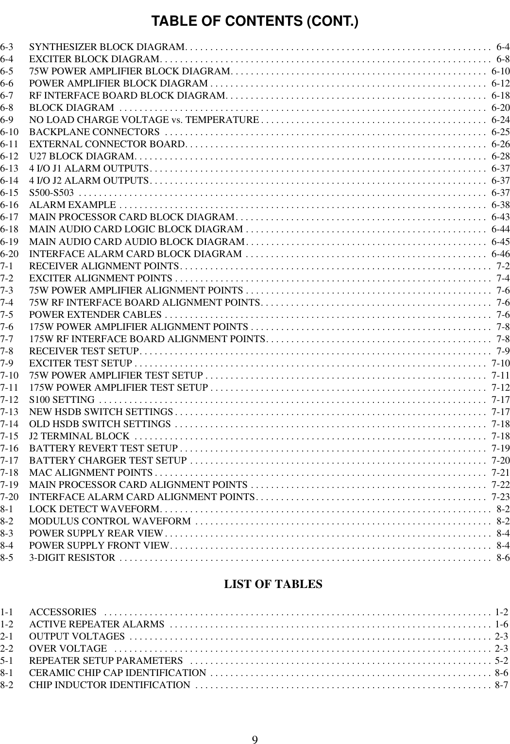


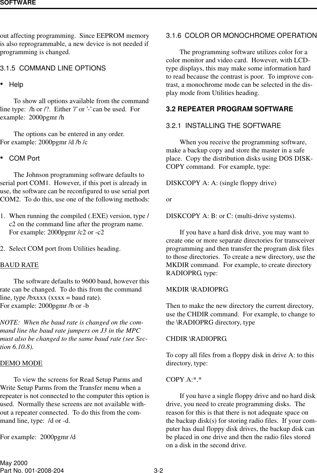
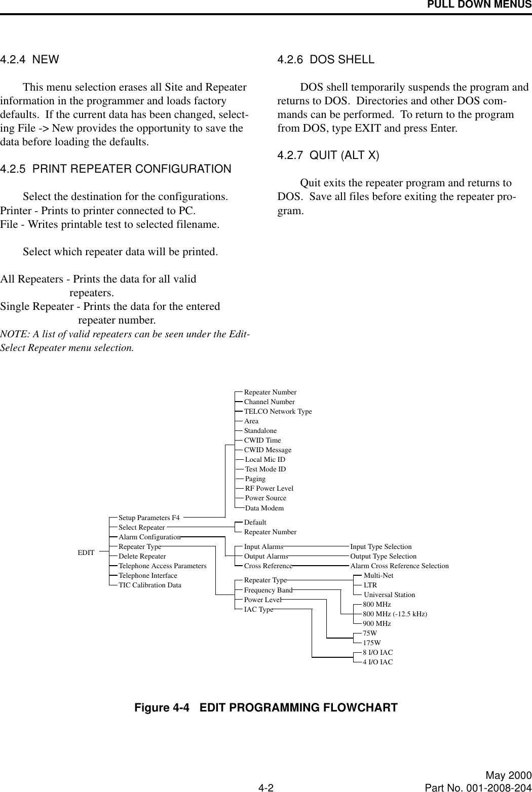
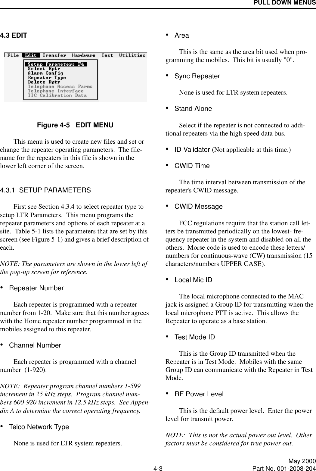
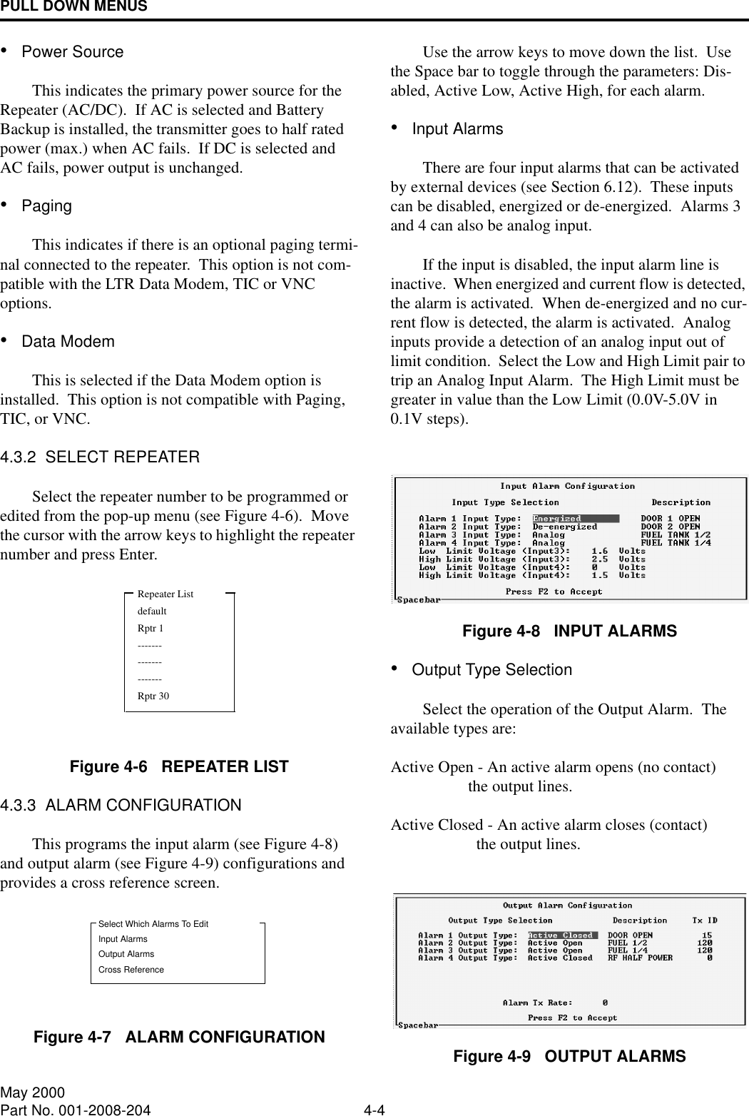
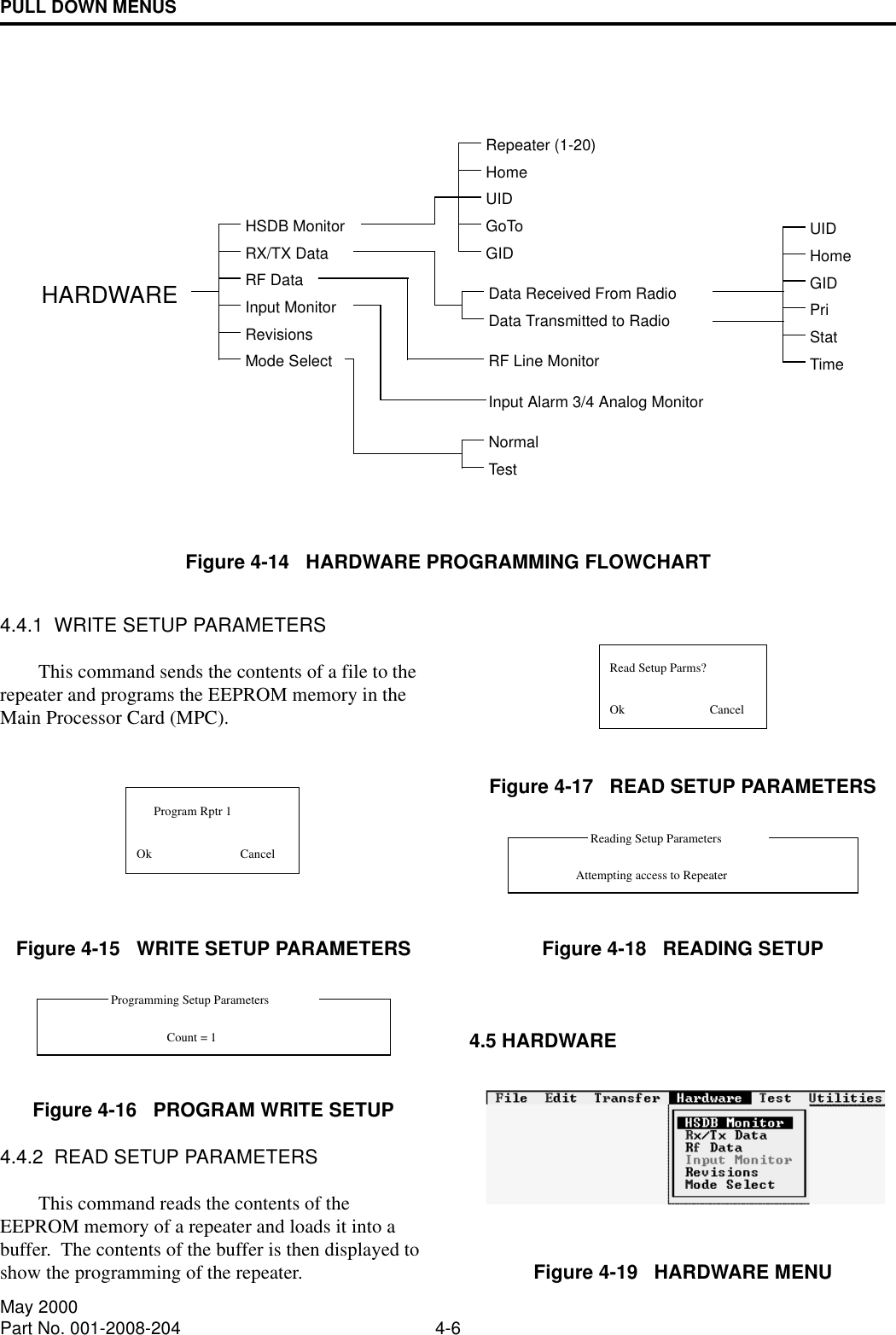
![PULL DOWN MENUS4-5 May 2000Part No. 001-2008-204•Alarm DescriptionThis is a text string (up to 15 characters) to describe the alarm. This test string is sent via Morse code if the alarm input is programmed with a Tx ID and an output is selected in the cross reference menu (see Figure 4-10).•Transmit IDEach of the 8-alarm outputs can be assigned a Group ID from 1-225. The default setting is 0 (zero) for disabled. This Group ID and the Repeater number identify an alarm that is active. This ID can be pro-grammed into a transceiver so that when the alarm is active, the alarm description is received in Morse code. •Alarm Transmit RateThis sets the time interval for transmitting the alarm message in Morse code. If more than one alarm is active, this is the inter-alarm time.•Cross ReferenceThe cross reference screen selects the output alarm that is activated by each input alarm. There are up to 48 alarms (0-47), 8 external input alarms and 40 internal alarms (see Table 1-2). There are eight output alarms. An alarm condition on any input can cause an output alarm. This screen configures which input alarm activates an output alarm.NOTE: More than one alarm condition can have the same output alarm (see Figure 4-10).Figure 4-10 ALARM CROSS REFERENCE4.3.4 REPEATER TYPEThis screen (see Figure 4-11) selects the repeater type (LTR signaling protocol and features): Frequency Band 800 MHz800 MHz [-12.5 kHz]900 MHzPower Level 75W 175WFigure 4-11 REPEATER TYPE4.3.5 DELETE REPEATERFigure 4-12 DELETE REPEATER4.3.6 TELEPHONE PARAMETERSRefer to the Telephone Interface Card manual, Part No. 004-2000-370, for information on the Tele-phone Access Parameters, Telephone Interface and TIC Calibration Data.4.4 TRANSFERFigure 4-13 TRANSFER MENUSelect Rptr To DeleteRptr 1](https://usermanual.wiki/E-F-Johnson/2422008-1/User-Guide-232313-Page-45.png)