E F Johnson 2422008-1 User Manual
E. F. Johnson Company
User Manual

1-1 October 1995
Part No. 001-2008-202
VIKING® VX
800 MHz LTR
75W-175W Repeater
Models: VX-RL82, VX-RL83
Part No. 242-2008-232/234
Fifth Printing
May 1998
Supersedes 001-2008-202
Part No. 001-2008-203 5-98mwp Printed in U.S.A.

1-2
October 1995
Part No. 001-2008-202

1-3 October 1995
Part No. 001-2008-202
VIKING® VX
800 MHz LTR REPEATER
PART NO. 242-2008-232/234
Copyright© 1998 by E.F. Johnson Company
E.F. Johnson company designs and manufactures two-way radio equipment to serve a wide variety of communications needs.
EFJohnson® produces equipment for the mobile telephone and land mobile radio services which include business, industrial,
government, public safety, and personal users.
LAND MOBILE PRODUCT WARRANTY
The manufacturer’s warranty statement for this product is available from your product supplier or from the EF Johnson, Inc.,
299 Johnson Avenue, Box 1249, Waseca, MN 56093-0514. Phone (507) 835-6222.
WARNING
DO NOT allow the antenna to touch or come in very close proximity with the eyes, face, or any exposed body parts while the
radio is transmitting.
DO NOT operate the transmitter of a mobile radio when a person outside the vehicle is within one (1) meter of the antenna.
DO NOT operate the transmitter of a stationary radio (base station, repeater or marine radio) when a person is within one (1)
meter of the antenna.
DO NOT operate the radio in explosive or flammable atmospheres. The transmitted radio energy could trigger blasting caps
or cause an explosion.
DO NOT operate the radio without the proper antenna installed.
DO NOT allow children to operate or play with this equipment.
NOTE: The above warning list is not intended to include all hazards that may be encountered when using this radio.
This device complies with Part 15 of the FCC rules. Operation is subject to the condition that this device does not cause harm-
ful interference. In addition, changes or modification to this equipment not expressly approved by EF Johnson could void the
user’s authority to operate this equipment (FCC rules, 47CFR Part 15.19).
SAFETY INFORMATION
Proper operation of this radio will result in user exposure below the Occupational Safety and Health Act and Federal Commu-
nication Commission limits.
The information in this document is subject to change without notice.
EF Johnson will not be liable for any misunderstanding due to misinformation or errors found in this document.
LTR, Multi-Net, Viking Head/EFJohnson Logo, Call Guard and SUMMIT are registered trademarks of Transcrypt Interna-
tional, Inc. All other company and/or product names used in this manual are trademarks and/or registered trademarks of their
respective manufacturer.

TABLE OF CONTENTS
1
1 INTRODUCTION AND OPERATION
1.1 SCOPE OF MANUAL . . . . . . . . . . . . . . . . . . . . . . . . . . . . . . . . . . . . . . . . . . . . . . . . . . . . . . . . . . . . . . . . . . . . . . . 1-1
1.2 REPEATER DESCRIPTION . . . . . . . . . . . . . . . . . . . . . . . . . . . . . . . . . . . . . . . . . . . . . . . . . . . . . . . . . . . . . . . . . 1-1
1.3 REPEATER IDENTIFICATION . . . . . . . . . . . . . . . . . . . . . . . . . . . . . . . . . . . . . . . . . . . . . . . . . . . . . . . . . . . . . . 1-1
1.4 MODEL NUMBER BREAKDOWN . . . . . . . . . . . . . . . . . . . . . . . . . . . . . . . . . . . . . . . . . . . . . . . . . . . . . . . . . . . 1-1
1.5 ACCESSORIES . . . . . . . . . . . . . . . . . . . . . . . . . . . . . . . . . . . . . . . . . . . . . . . . . . . . . . . . . . . . . . . . . . . . . . . . . . . . 1-2
1.6 PRODUCT WARRANTY . . . . . . . . . . . . . . . . . . . . . . . . . . . . . . . . . . . . . . . . . . . . . . . . . . . . . . . . . . . . . . . . . . . . 1-3
1.7 FACTORY CUSTOMER SERVICE . . . . . . . . . . . . . . . . . . . . . . . . . . . . . . . . . . . . . . . . . . . . . . . . . . . . . . . . . . . 1-3
1.8 FACTORY RETURNS . . . . . . . . . . . . . . . . . . . . . . . . . . . . . . . . . . . . . . . . . . . . . . . . . . . . . . . . . . . . . . . . . . . . . . 1-3
1.9 REPLACEMENT PARTS. . . . . . . . . . . . . . . . . . . . . . . . . . . . . . . . . . . . . . . . . . . . . . . . . . . . . . . . . . . . . . . . . . . . 1-4
1.10 INTERNET HOME PAGE . . . . . . . . . . . . . . . . . . . . . . . . . . . . . . . . . . . . . . . . . . . . . . . . . . . . . . . . . . . . . . . . . . . 1-4
1.11 SOFTWARE UPDATES/REVISIONS . . . . . . . . . . . . . . . . . . . . . . . . . . . . . . . . . . . . . . . . . . . . . . . . . . . . . . . . . 1-4
1.12 REPEATER OPERATION . . . . . . . . . . . . . . . . . . . . . . . . . . . . . . . . . . . . . . . . . . . . . . . . . . . . . . . . . . . . . . . . . . . 1-4
MAIN PROCESSOR CARD (MPC) . . . . . . . . . . . . . . . . . . . . . . . . . . . . . . . . . . . . . . . . . . . . . . . . . . . . . . . . . . . . . 1-4
MAIN AUDIO CARD (MAC). . . . . . . . . . . . . . . . . . . . . . . . . . . . . . . . . . . . . . . . . . . . . . . . . . . . . . . . . . . . . . . . . . 1-7
INTERFACE ALARM CARD (IAC) . . . . . . . . . . . . . . . . . . . . . . . . . . . . . . . . . . . . . . . . . . . . . . . . . . . . . . . . . . . . 1-7
POWER SUPPLY . . . . . . . . . . . . . . . . . . . . . . . . . . . . . . . . . . . . . . . . . . . . . . . . . . . . . . . . . . . . . . . . . . . . . . . . . . . 1-8
1.13 REPEATER INFORMATION . . . . . . . . . . . . . . . . . . . . . . . . . . . . . . . . . . . . . . . . . . . . . . . . . . . . . . . . . . . . . . . . 1-8
INTRODUCTION . . . . . . . . . . . . . . . . . . . . . . . . . . . . . . . . . . . . . . . . . . . . . . . . . . . . . . . . . . . . . . . . . . . . . . . . . . . 1-8
HOME REPEATERS. . . . . . . . . . . . . . . . . . . . . . . . . . . . . . . . . . . . . . . . . . . . . . . . . . . . . . . . . . . . . . . . . . . . . . . . . 1-8
INTER-REPEATER DATA COMMUNICATION. . . . . . . . . . . . . . . . . . . . . . . . . . . . . . . . . . . . . . . . . . . . . . . . . . 1-8
MOBILE TRANSCEIVERS . . . . . . . . . . . . . . . . . . . . . . . . . . . . . . . . . . . . . . . . . . . . . . . . . . . . . . . . . . . . . . . . . . . 1-8
1.14 REPEATER DATA BUS SIGNALING . . . . . . . . . . . . . . . . . . . . . . . . . . . . . . . . . . . . . . . . . . . . . . . . . . . . . . . . . 1-8
GENERAL . . . . . . . . . . . . . . . . . . . . . . . . . . . . . . . . . . . . . . . . . . . . . . . . . . . . . . . . . . . . . . . . . . . . . . . . . . . . . . . . . 1-8
MOBILE DATA MESSAGE ORDER . . . . . . . . . . . . . . . . . . . . . . . . . . . . . . . . . . . . . . . . . . . . . . . . . . . . . . . . . . . 1-9
ID VALIDATOR OPERATION . . . . . . . . . . . . . . . . . . . . . . . . . . . . . . . . . . . . . . . . . . . . . . . . . . . . . . . . . . . . . . . . 1-9
2 INSTALLATION
2.1 INTRODUCTION . . . . . . . . . . . . . . . . . . . . . . . . . . . . . . . . . . . . . . . . . . . . . . . . . . . . . . . . . . . . . . . . . . . . . . . . . . 2-1
SITE PREPARATION AND ANTENNA INSTALLATION. . . . . . . . . . . . . . . . . . . . . . . . . . . . . . . . . . . . . . . . . . 2-1
2.2 ENVIRONMENT . . . . . . . . . . . . . . . . . . . . . . . . . . . . . . . . . . . . . . . . . . . . . . . . . . . . . . . . . . . . . . . . . . . . . . . . . . . 2-1
2.3 VENTILATION . . . . . . . . . . . . . . . . . . . . . . . . . . . . . . . . . . . . . . . . . . . . . . . . . . . . . . . . . . . . . . . . . . . . . . . . . . . . 2-1
2.4 AC POWER . . . . . . . . . . . . . . . . . . . . . . . . . . . . . . . . . . . . . . . . . . . . . . . . . . . . . . . . . . . . . . . . . . . . . . . . . . . . . . . 2-2
2.5 BATTERY BACKUP. . . . . . . . . . . . . . . . . . . . . . . . . . . . . . . . . . . . . . . . . . . . . . . . . . . . . . . . . . . . . . . . . . . . . . . . 2-2
2.6 800W POWER SUPPLY . . . . . . . . . . . . . . . . . . . . . . . . . . . . . . . . . . . . . . . . . . . . . . . . . . . . . . . . . . . . . . . . . . . . . 2-2
AC INPUT REQUIREMENTS . . . . . . . . . . . . . . . . . . . . . . . . . . . . . . . . . . . . . . . . . . . . . . . . . . . . . . . . . . . . . . . . . 2-3
2.7 GROUNDING. . . . . . . . . . . . . . . . . . . . . . . . . . . . . . . . . . . . . . . . . . . . . . . . . . . . . . . . . . . . . . . . . . . . . . . . . . . . . . 2-4
PROTECTION GUIDELINES . . . . . . . . . . . . . . . . . . . . . . . . . . . . . . . . . . . . . . . . . . . . . . . . . . . . . . . . . . . . . . . . . 2-5
2.8 UNPACKING AND INSPECTION . . . . . . . . . . . . . . . . . . . . . . . . . . . . . . . . . . . . . . . . . . . . . . . . . . . . . . . . . . . . 2-5
2.9 REPEATER DATA BUS INSTALLATION . . . . . . . . . . . . . . . . . . . . . . . . . . . . . . . . . . . . . . . . . . . . . . . . . . . . . 2-6
MPC DATA BUS SWITCH SETTINGS. . . . . . . . . . . . . . . . . . . . . . . . . . . . . . . . . . . . . . . . . . . . . . . . . . . . . . . . . . 2-6
MPC DATA BUS JUMPER SETTINGS. . . . . . . . . . . . . . . . . . . . . . . . . . . . . . . . . . . . . . . . . . . . . . . . . . . . . . . . . . 2-6
2.10 CONNECTING RECEIVE AND TRANSMIT ANTENNAS . . . . . . . . . . . . . . . . . . . . . . . . . . . . . . . . . . . . . . . 2-7
3 SOFTWARE
3.1 INTRODUCTION . . . . . . . . . . . . . . . . . . . . . . . . . . . . . . . . . . . . . . . . . . . . . . . . . . . . . . . . . . . . . . . . . . . . . . . . . . 3-1
HOW TO USE THIS MANUAL . . . . . . . . . . . . . . . . . . . . . . . . . . . . . . . . . . . . . . . . . . . . . . . . . . . . . . . . . . . . . . . . 3-1
GETTING STARTED . . . . . . . . . . . . . . . . . . . . . . . . . . . . . . . . . . . . . . . . . . . . . . . . . . . . . . . . . . . . . . . . . . . . . . . . 3-1
COMPUTER DESCRIPTION . . . . . . . . . . . . . . . . . . . . . . . . . . . . . . . . . . . . . . . . . . . . . . . . . . . . . . . . . . . . . . . . . . 3-1
EEPROM DATA STORAGE . . . . . . . . . . . . . . . . . . . . . . . . . . . . . . . . . . . . . . . . . . . . . . . . . . . . . . . . . . . . . . . . . . 3-1
COMMAND LINE OPTIONS. . . . . . . . . . . . . . . . . . . . . . . . . . . . . . . . . . . . . . . . . . . . . . . . . . . . . . . . . . . . . . . . . . 3-2
COLOR OR MONOCHROME OPERATION . . . . . . . . . . . . . . . . . . . . . . . . . . . . . . . . . . . . . . . . . . . . . . . . . . . . . 3-2

TABLE OF CONTENTS (CONT.)
2
3.2 REPEATER PROGRAM SOFTWARE. . . . . . . . . . . . . . . . . . . . . . . . . . . . . . . . . . . . . . . . . . . . . . . . . . . . . . . . . 3-2
INSTALLING THE SOFTWARE . . . . . . . . . . . . . . . . . . . . . . . . . . . . . . . . . . . . . . . . . . . . . . . . . . . . . . . . . . . . . . 3-2
MINIMUM FREE MEMORY REQUIRED . . . . . . . . . . . . . . . . . . . . . . . . . . . . . . . . . . . . . . . . . . . . . . . . . . . . . . 3-3
3.3 REPEATER PROGRAMMER . . . . . . . . . . . . . . . . . . . . . . . . . . . . . . . . . . . . . . . . . . . . . . . . . . . . . . . . . . . . . . . . 3-3
PROGRAM FILES . . . . . . . . . . . . . . . . . . . . . . . . . . . . . . . . . . . . . . . . . . . . . . . . . . . . . . . . . . . . . . . . . . . . . . . . . . 3-3
3.4 ALIGNMENT SOFTWARE . . . . . . . . . . . . . . . . . . . . . . . . . . . . . . . . . . . . . . . . . . . . . . . . . . . . . . . . . . . . . . . . . . 3-3
3.5 HELP F1 . . . . . . . . . . . . . . . . . . . . . . . . . . . . . . . . . . . . . . . . . . . . . . . . . . . . . . . . . . . . . . . . . . . . . . . . . . . . . . . . . . 3-4
4 PULL DOWN MENUS
4.1 MENU DISPLAYS . . . . . . . . . . . . . . . . . . . . . . . . . . . . . . . . . . . . . . . . . . . . . . . . . . . . . . . . . . . . . . . . . . . . . . . . . . 4-1
4.2 FILE MENU . . . . . . . . . . . . . . . . . . . . . . . . . . . . . . . . . . . . . . . . . . . . . . . . . . . . . . . . . . . . . . . . . . . . . . . . . . . . . . . 4-1
LOAD . . . . . . . . . . . . . . . . . . . . . . . . . . . . . . . . . . . . . . . . . . . . . . . . . . . . . . . . . . . . . . . . . . . . . . . . . . . . . . . . . . . . 4-1
SAVE . . . . . . . . . . . . . . . . . . . . . . . . . . . . . . . . . . . . . . . . . . . . . . . . . . . . . . . . . . . . . . . . . . . . . . . . . . . . . . . . . . . . 4-1
SAVE AS . . . . . . . . . . . . . . . . . . . . . . . . . . . . . . . . . . . . . . . . . . . . . . . . . . . . . . . . . . . . . . . . . . . . . . . . . . . . . . . . . 4-1
NEW . . . . . . . . . . . . . . . . . . . . . . . . . . . . . . . . . . . . . . . . . . . . . . . . . . . . . . . . . . . . . . . . . . . . . . . . . . . . . . . . . . . . . 4-2
PRINT REPEATER CONFIGURATION . . . . . . . . . . . . . . . . . . . . . . . . . . . . . . . . . . . . . . . . . . . . . . . . . . . . . . . . 4-2
DOS SHELL . . . . . . . . . . . . . . . . . . . . . . . . . . . . . . . . . . . . . . . . . . . . . . . . . . . . . . . . . . . . . . . . . . . . . . . . . . . . . . . 4-2
QUIT (ALT X) . . . . . . . . . . . . . . . . . . . . . . . . . . . . . . . . . . . . . . . . . . . . . . . . . . . . . . . . . . . . . . . . . . . . . . . . . . . . . 4-2
4.3 EDIT. . . . . . . . . . . . . . . . . . . . . . . . . . . . . . . . . . . . . . . . . . . . . . . . . . . . . . . . . . . . . . . . . . . . . . . . . . . . . . . . . . . . . . 4-3
SETUP PARAMETERS. . . . . . . . . . . . . . . . . . . . . . . . . . . . . . . . . . . . . . . . . . . . . . . . . . . . . . . . . . . . . . . . . . . . . . 4-3
SELECT REPEATER. . . . . . . . . . . . . . . . . . . . . . . . . . . . . . . . . . . . . . . . . . . . . . . . . . . . . . . . . . . . . . . . . . . . . . . . 4-4
ALARM CONFIGURATION . . . . . . . . . . . . . . . . . . . . . . . . . . . . . . . . . . . . . . . . . . . . . . . . . . . . . . . . . . . . . . . . . 4-4
REPEATER TYPE . . . . . . . . . . . . . . . . . . . . . . . . . . . . . . . . . . . . . . . . . . . . . . . . . . . . . . . . . . . . . . . . . . . . . . . . . . 4-5
DELETE REPEATER . . . . . . . . . . . . . . . . . . . . . . . . . . . . . . . . . . . . . . . . . . . . . . . . . . . . . . . . . . . . . . . . . . . . . . . 4-5
TELEPHONE PARAMETERS . . . . . . . . . . . . . . . . . . . . . . . . . . . . . . . . . . . . . . . . . . . . . . . . . . . . . . . . . . . . . . . . 4-5
4.4 TRANSFER. . . . . . . . . . . . . . . . . . . . . . . . . . . . . . . . . . . . . . . . . . . . . . . . . . . . . . . . . . . . . . . . . . . . . . . . . . . . . . . . 4-5
WRITE SETUP PARAMETERS . . . . . . . . . . . . . . . . . . . . . . . . . . . . . . . . . . . . . . . . . . . . . . . . . . . . . . . . . . . . . . . 4-6
READ SETUP PARAMETERS. . . . . . . . . . . . . . . . . . . . . . . . . . . . . . . . . . . . . . . . . . . . . . . . . . . . . . . . . . . . . . . . 4-6
4.5 HARDWARE . . . . . . . . . . . . . . . . . . . . . . . . . . . . . . . . . . . . . . . . . . . . . . . . . . . . . . . . . . . . . . . . . . . . . . . . . . . . . . 4-6
HSDB MONITOR . . . . . . . . . . . . . . . . . . . . . . . . . . . . . . . . . . . . . . . . . . . . . . . . . . . . . . . . . . . . . . . . . . . . . . . . . . 4-7
RECEIVE/TRANSMIT DATA . . . . . . . . . . . . . . . . . . . . . . . . . . . . . . . . . . . . . . . . . . . . . . . . . . . . . . . . . . . . . . . . 4-7
RF DATA . . . . . . . . . . . . . . . . . . . . . . . . . . . . . . . . . . . . . . . . . . . . . . . . . . . . . . . . . . . . . . . . . . . . . . . . . . . . . . . . . 4-7
REVISION/VERSION . . . . . . . . . . . . . . . . . . . . . . . . . . . . . . . . . . . . . . . . . . . . . . . . . . . . . . . . . . . . . . . . . . . . . . . 4-8
MODE SELECT. . . . . . . . . . . . . . . . . . . . . . . . . . . . . . . . . . . . . . . . . . . . . . . . . . . . . . . . . . . . . . . . . . . . . . . . . . . . 4-8
4.6 TEST . . . . . . . . . . . . . . . . . . . . . . . . . . . . . . . . . . . . . . . . . . . . . . . . . . . . . . . . . . . . . . . . . . . . . . . . . . . . . . . . . . . . . 4-9
POWER AMPLIFIER . . . . . . . . . . . . . . . . . . . . . . . . . . . . . . . . . . . . . . . . . . . . . . . . . . . . . . . . . . . . . . . . . . . . . . . 4-9
RECEIVER. . . . . . . . . . . . . . . . . . . . . . . . . . . . . . . . . . . . . . . . . . . . . . . . . . . . . . . . . . . . . . . . . . . . . . . . . . . . . . . . 4-9
EXCITER . . . . . . . . . . . . . . . . . . . . . . . . . . . . . . . . . . . . . . . . . . . . . . . . . . . . . . . . . . . . . . . . . . . . . . . . . . . . . . . . . 4-9
FULL REPEATER . . . . . . . . . . . . . . . . . . . . . . . . . . . . . . . . . . . . . . . . . . . . . . . . . . . . . . . . . . . . . . . . . . . . . . . . . . 4-9
4.7 UTILITIES . . . . . . . . . . . . . . . . . . . . . . . . . . . . . . . . . . . . . . . . . . . . . . . . . . . . . . . . . . . . . . . . . . . . . . . . . . . . . . . . 4-9
COM PORT . . . . . . . . . . . . . . . . . . . . . . . . . . . . . . . . . . . . . . . . . . . . . . . . . . . . . . . . . . . . . . . . . . . . . . . . . . . . . . . 4-9
DISPLAY MODE. . . . . . . . . . . . . . . . . . . . . . . . . . . . . . . . . . . . . . . . . . . . . . . . . . . . . . . . . . . . . . . . . . . . . . . . . . . 4-9
USER LEVEL. . . . . . . . . . . . . . . . . . . . . . . . . . . . . . . . . . . . . . . . . . . . . . . . . . . . . . . . . . . . . . . . . . . . . . . . . . . . . . 4-9
5 REPEATER PROGRAMMING
5.1 CREATING A NEW FILE . . . . . . . . . . . . . . . . . . . . . . . . . . . . . . . . . . . . . . . . . . . . . . . . . . . . . . . . . . . . . . . . . . . 5-1
SELECT REPEATER TO EDIT . . . . . . . . . . . . . . . . . . . . . . . . . . . . . . . . . . . . . . . . . . . . . . . . . . . . . . . . . . . . . . . 5-1
5.2 ADDING A REPEATER TO A FILE. . . . . . . . . . . . . . . . . . . . . . . . . . . . . . . . . . . . . . . . . . . . . . . . . . . . . . . . . . . 5-1

TABLE OF CONTENTS (CONT.)
3
6 CIRCUIT DESCRIPTION
6.1 RECEIVER. . . . . . . . . . . . . . . . . . . . . . . . . . . . . . . . . . . . . . . . . . . . . . . . . . . . . . . . . . . . . . . . . . . . . . . . . . . . . . . . 6-1
INTRODUCTION . . . . . . . . . . . . . . . . . . . . . . . . . . . . . . . . . . . . . . . . . . . . . . . . . . . . . . . . . . . . . . . . . . . . . . . . . . . 6-1
REGULATED VOLTAGE SUPPLIES . . . . . . . . . . . . . . . . . . . . . . . . . . . . . . . . . . . . . . . . . . . . . . . . . . . . . . . . . . . 6-1
HELICAL FILTER (L201-L203), RF AMPLIFIER (Q201). . . . . . . . . . . . . . . . . . . . . . . . . . . . . . . . . . . . . . . . . . . 6-1
FIRST MIXER (U201), CRYSTAL FILTER (Z201/Z202) . . . . . . . . . . . . . . . . . . . . . . . . . . . . . . . . . . . . . . . . . . . 6-1
IF AMPLIFIER (Q202), CRYSTAL FILTER (Z203/Z204) . . . . . . . . . . . . . . . . . . . . . . . . . . . . . . . . . . . . . . . . . . . 6-1
SECOND MIXER/DETECTOR (U202) . . . . . . . . . . . . . . . . . . . . . . . . . . . . . . . . . . . . . . . . . . . . . . . . . . . . . . . . . . 6-2
WIDEBAND AUDIO AMPLIFIER (U203B) . . . . . . . . . . . . . . . . . . . . . . . . . . . . . . . . . . . . . . . . . . . . . . . . . . . . . . 6-3
RSSI AMPLIFIER (U203A) . . . . . . . . . . . . . . . . . . . . . . . . . . . . . . . . . . . . . . . . . . . . . . . . . . . . . . . . . . . . . . . . . . . 6-3
VCO (A006) . . . . . . . . . . . . . . . . . . . . . . . . . . . . . . . . . . . . . . . . . . . . . . . . . . . . . . . . . . . . . . . . . . . . . . . . . . . . . . . . 6-3
ACTIVE FILTER (Q801) . . . . . . . . . . . . . . . . . . . . . . . . . . . . . . . . . . . . . . . . . . . . . . . . . . . . . . . . . . . . . . . . . . . . . 6-3
BUFFER (Q208, Q209) . . . . . . . . . . . . . . . . . . . . . . . . . . . . . . . . . . . . . . . . . . . . . . . . . . . . . . . . . . . . . . . . . . . . . . . 6-3
SYNTHESIZER (U209). . . . . . . . . . . . . . . . . . . . . . . . . . . . . . . . . . . . . . . . . . . . . . . . . . . . . . . . . . . . . . . . . . . . . . . 6-3
BUFFER AMPLIFIER (Q210, Q211) . . . . . . . . . . . . . . . . . . . . . . . . . . . . . . . . . . . . . . . . . . . . . . . . . . . . . . . . . . . . 6-5
LOCK DETECT. . . . . . . . . . . . . . . . . . . . . . . . . . . . . . . . . . . . . . . . . . . . . . . . . . . . . . . . . . . . . . . . . . . . . . . . . . . . . 6-5
BUFFER AMPLIFIER (Q214, Q215) . . . . . . . . . . . . . . . . . . . . . . . . . . . . . . . . . . . . . . . . . . . . . . . . . . . . . . . . . . . . 6-5
RF AMPLIFIERS (Q216, Q217) . . . . . . . . . . . . . . . . . . . . . . . . . . . . . . . . . . . . . . . . . . . . . . . . . . . . . . . . . . . . . . . . 6-5
6.2 EXCITER . . . . . . . . . . . . . . . . . . . . . . . . . . . . . . . . . . . . . . . . . . . . . . . . . . . . . . . . . . . . . . . . . . . . . . . . . . . . . . . . . 6-6
VCO (A007) . . . . . . . . . . . . . . . . . . . . . . . . . . . . . . . . . . . . . . . . . . . . . . . . . . . . . . . . . . . . . . . . . . . . . . . . . . . . . . . . 6-6
VCO AND TCXO FREQUENCY MODULATION. . . . . . . . . . . . . . . . . . . . . . . . . . . . . . . . . . . . . . . . . . . . . . . . . 6-6
ACTIVE FILTER. . . . . . . . . . . . . . . . . . . . . . . . . . . . . . . . . . . . . . . . . . . . . . . . . . . . . . . . . . . . . . . . . . . . . . . . . . . . 6-6
BUFFER (Q406, Q407) . . . . . . . . . . . . . . . . . . . . . . . . . . . . . . . . . . . . . . . . . . . . . . . . . . . . . . . . . . . . . . . . . . . . . . . 6-7
SYNTHESIZER (U403). . . . . . . . . . . . . . . . . . . . . . . . . . . . . . . . . . . . . . . . . . . . . . . . . . . . . . . . . . . . . . . . . . . . . . . 6-7
BUFFER AMPLIFIER (Q403, Q404) . . . . . . . . . . . . . . . . . . . . . . . . . . . . . . . . . . . . . . . . . . . . . . . . . . . . . . . . . . . . 6-8
BUFFER AMPLIFIER (Q406, Q407) . . . . . . . . . . . . . . . . . . . . . . . . . . . . . . . . . . . . . . . . . . . . . . . . . . . . . . . . . . . . 6-9
LOCK DETECT. . . . . . . . . . . . . . . . . . . . . . . . . . . . . . . . . . . . . . . . . . . . . . . . . . . . . . . . . . . . . . . . . . . . . . . . . . . . . 6-9
BUFFER AMPLIFIER (Q410, Q411) . . . . . . . . . . . . . . . . . . . . . . . . . . . . . . . . . . . . . . . . . . . . . . . . . . . . . . . . . . . . 6-9
RF AMPLIFIERS (Q412, Q413) . . . . . . . . . . . . . . . . . . . . . . . . . . . . . . . . . . . . . . . . . . . . . . . . . . . . . . . . . . . . . . . . 6-9
6.3 75W POWER AMPLIFIER . . . . . . . . . . . . . . . . . . . . . . . . . . . . . . . . . . . . . . . . . . . . . . . . . . . . . . . . . . . . . . . . . . 6-9
AMPLIFIER/PREDRIVER (U501). . . . . . . . . . . . . . . . . . . . . . . . . . . . . . . . . . . . . . . . . . . . . . . . . . . . . . . . . . . . . . 6-9
DRIVER (Q501). . . . . . . . . . . . . . . . . . . . . . . . . . . . . . . . . . . . . . . . . . . . . . . . . . . . . . . . . . . . . . . . . . . . . . . . . . . . . 6-9
FINAL AMPLIFIERS (Q502, Q503). . . . . . . . . . . . . . . . . . . . . . . . . . . . . . . . . . . . . . . . . . . . . . . . . . . . . . . . . . . . . 6-9
POWER DETECTORS (U504A, U502B). . . . . . . . . . . . . . . . . . . . . . . . . . . . . . . . . . . . . . . . . . . . . . . . . . . . . . . . 6-10
THERMAL SENSOR (U503) . . . . . . . . . . . . . . . . . . . . . . . . . . . . . . . . . . . . . . . . . . . . . . . . . . . . . . . . . . . . . . . . . 6-10
FORWARD/REVERSE POWER DETECT, CIRCULATOR, LOW-PASS FILTER . . . . . . . . . . . . . . . . . . . . . . 6-10
6.4 175W POWER AMPLIFIER . . . . . . . . . . . . . . . . . . . . . . . . . . . . . . . . . . . . . . . . . . . . . . . . . . . . . . . . . . . . . . . . 6-11
GAIN BLOCK (U501). . . . . . . . . . . . . . . . . . . . . . . . . . . . . . . . . . . . . . . . . . . . . . . . . . . . . . . . . . . . . . . . . . . . . . . 6-11
DRIVER (Q502). . . . . . . . . . . . . . . . . . . . . . . . . . . . . . . . . . . . . . . . . . . . . . . . . . . . . . . . . . . . . . . . . . . . . . . . . . . . 6-11
FINAL AMPLIFIERS (Q701, Q702, Q703, Q704). . . . . . . . . . . . . . . . . . . . . . . . . . . . . . . . . . . . . . . . . . . . . . . . . 6-11
POWER DETECTORS . . . . . . . . . . . . . . . . . . . . . . . . . . . . . . . . . . . . . . . . . . . . . . . . . . . . . . . . . . . . . . . . . . . . . . 6-11
THERMAL SENSOR (U503) . . . . . . . . . . . . . . . . . . . . . . . . . . . . . . . . . . . . . . . . . . . . . . . . . . . . . . . . . . . . . . . . . 6-11
FORWARD/REVERSE POWER DETECT, CIRCULATOR, LOW-PASS FILTER . . . . . . . . . . . . . . . . . . . . . . 6-11
6.5 RF INTERFACE BOARD. . . . . . . . . . . . . . . . . . . . . . . . . . . . . . . . . . . . . . . . . . . . . . . . . . . . . . . . . . . . . . . . . . . 6-12
POWER CONNECTOR. . . . . . . . . . . . . . . . . . . . . . . . . . . . . . . . . . . . . . . . . . . . . . . . . . . . . . . . . . . . . . . . . . . . . . 6-12
SIGNAL CONNECTOR (J101). . . . . . . . . . . . . . . . . . . . . . . . . . . . . . . . . . . . . . . . . . . . . . . . . . . . . . . . . . . . . . . . 6-12
FAN CONNECTOR (J104) . . . . . . . . . . . . . . . . . . . . . . . . . . . . . . . . . . . . . . . . . . . . . . . . . . . . . . . . . . . . . . . . . . . 6-14
POWER AMPLIFIER CONNECTIONS. . . . . . . . . . . . . . . . . . . . . . . . . . . . . . . . . . . . . . . . . . . . . . . . . . . . . . . . . 6-15
EXCITER CONNECTOR (J102). . . . . . . . . . . . . . . . . . . . . . . . . . . . . . . . . . . . . . . . . . . . . . . . . . . . . . . . . . . . . . . 6-16
RECEIVER CONNECTOR (J103) . . . . . . . . . . . . . . . . . . . . . . . . . . . . . . . . . . . . . . . . . . . . . . . . . . . . . . . . . . . . . 6-17

TABLE OF CONTENTS (CONT.)
4
6.6 800W POWER SUPPLY . . . . . . . . . . . . . . . . . . . . . . . . . . . . . . . . . . . . . . . . . . . . . . . . . . . . . . . . . . . . . . . . . . . . 6-19
FILTER BOARD . . . . . . . . . . . . . . . . . . . . . . . . . . . . . . . . . . . . . . . . . . . . . . . . . . . . . . . . . . . . . . . . . . . . . . . . . . 6-19
POWER FACTOR CORRECTION . . . . . . . . . . . . . . . . . . . . . . . . . . . . . . . . . . . . . . . . . . . . . . . . . . . . . . . . . . . . 6-19
MAIN PULSE WIDTH MODULATOR . . . . . . . . . . . . . . . . . . . . . . . . . . . . . . . . . . . . . . . . . . . . . . . . . . . . . . . . 6-19
SYNCHRONIZING CIRCUITS . . . . . . . . . . . . . . . . . . . . . . . . . . . . . . . . . . . . . . . . . . . . . . . . . . . . . . . . . . . . . . 6-21
FAN AND THERMAL SHUTDOWN. . . . . . . . . . . . . . . . . . . . . . . . . . . . . . . . . . . . . . . . . . . . . . . . . . . . . . . . . . 6-21
+15V CONVERTER . . . . . . . . . . . . . . . . . . . . . . . . . . . . . . . . . . . . . . . . . . . . . . . . . . . . . . . . . . . . . . . . . . . . . . . 6-22
+5V CONVERTER . . . . . . . . . . . . . . . . . . . . . . . . . . . . . . . . . . . . . . . . . . . . . . . . . . . . . . . . . . . . . . . . . . . . . . . . 6-22
-5V CONVERTER . . . . . . . . . . . . . . . . . . . . . . . . . . . . . . . . . . . . . . . . . . . . . . . . . . . . . . . . . . . . . . . . . . . . . . . . . 6-22
POWER SUPPLY REPAIR AND ALIGNMENT. . . . . . . . . . . . . . . . . . . . . . . . . . . . . . . . . . . . . . . . . . . . . . . . . 6-22
6.7 BATTERY BACK-UP MODULE. . . . . . . . . . . . . . . . . . . . . . . . . . . . . . . . . . . . . . . . . . . . . . . . . . . . . . . . . . . . . 6-23
OPERATION . . . . . . . . . . . . . . . . . . . . . . . . . . . . . . . . . . . . . . . . . . . . . . . . . . . . . . . . . . . . . . . . . . . . . . . . . . . . . 6-23
CHARGER . . . . . . . . . . . . . . . . . . . . . . . . . . . . . . . . . . . . . . . . . . . . . . . . . . . . . . . . . . . . . . . . . . . . . . . . . . . . . . . 6-23
REVERSE BATTERY PROTECTION . . . . . . . . . . . . . . . . . . . . . . . . . . . . . . . . . . . . . . . . . . . . . . . . . . . . . . . . . 6-24
ENGAGING THE RELAY . . . . . . . . . . . . . . . . . . . . . . . . . . . . . . . . . . . . . . . . . . . . . . . . . . . . . . . . . . . . . . . . . . 6-24
OVER/UNDERVOLTAGE SHUTDOWN . . . . . . . . . . . . . . . . . . . . . . . . . . . . . . . . . . . . . . . . . . . . . . . . . . . . . . 6-24
BBM FAN CONTROL. . . . . . . . . . . . . . . . . . . . . . . . . . . . . . . . . . . . . . . . . . . . . . . . . . . . . . . . . . . . . . . . . . . . . . 6-25
6.8 CARD RACK . . . . . . . . . . . . . . . . . . . . . . . . . . . . . . . . . . . . . . . . . . . . . . . . . . . . . . . . . . . . . . . . . . . . . . . . . . . . . 6-25
6.9 EXTERNAL CONNECTOR BOARD . . . . . . . . . . . . . . . . . . . . . . . . . . . . . . . . . . . . . . . . . . . . . . . . . . . . . . . . . 6-26
6.10 MAIN PROCESSOR CARD . . . . . . . . . . . . . . . . . . . . . . . . . . . . . . . . . . . . . . . . . . . . . . . . . . . . . . . . . . . . . . . . . 6-27
INTRODUCTION . . . . . . . . . . . . . . . . . . . . . . . . . . . . . . . . . . . . . . . . . . . . . . . . . . . . . . . . . . . . . . . . . . . . . . . . . 6-27
MAIN CONTROLLER MICROPROCESSOR (U27). . . . . . . . . . . . . . . . . . . . . . . . . . . . . . . . . . . . . . . . . . . . . . 6-27
HIGH SPEED DATA BUS MICROPROCESSOR (U13). . . . . . . . . . . . . . . . . . . . . . . . . . . . . . . . . . . . . . . . . . . 6-28
CHIP SELECT DECODERS (U15/U4) . . . . . . . . . . . . . . . . . . . . . . . . . . . . . . . . . . . . . . . . . . . . . . . . . . . . . . . . . 6-29
P1 SIGNAL CONNECTOR . . . . . . . . . . . . . . . . . . . . . . . . . . . . . . . . . . . . . . . . . . . . . . . . . . . . . . . . . . . . . . . . . . 6-29
J1 COMPUTER CONNECTOR. . . . . . . . . . . . . . . . . . . . . . . . . . . . . . . . . . . . . . . . . . . . . . . . . . . . . . . . . . . . . . . 6-30
J2 MEMORY SELECT . . . . . . . . . . . . . . . . . . . . . . . . . . . . . . . . . . . . . . . . . . . . . . . . . . . . . . . . . . . . . . . . . . . . . 6-30
J3 BAUD RATE . . . . . . . . . . . . . . . . . . . . . . . . . . . . . . . . . . . . . . . . . . . . . . . . . . . . . . . . . . . . . . . . . . . . . . . . . . . 6-30
S2/S3 HSDB SETTINGS . . . . . . . . . . . . . . . . . . . . . . . . . . . . . . . . . . . . . . . . . . . . . . . . . . . . . . . . . . . . . . . . . . . . 6-30
J4 EPROM MEMORY LOADING . . . . . . . . . . . . . . . . . . . . . . . . . . . . . . . . . . . . . . . . . . . . . . . . . . . . . . . . . . . . 6-30
J5 HSDB SPEED . . . . . . . . . . . . . . . . . . . . . . . . . . . . . . . . . . . . . . . . . . . . . . . . . . . . . . . . . . . . . . . . . . . . . . . . . . 6-30
J6 WATCHDOG. . . . . . . . . . . . . . . . . . . . . . . . . . . . . . . . . . . . . . . . . . . . . . . . . . . . . . . . . . . . . . . . . . . . . . . . . . . 6-30
6.11 MAIN AUDIO CARD. . . . . . . . . . . . . . . . . . . . . . . . . . . . . . . . . . . . . . . . . . . . . . . . . . . . . . . . . . . . . . . . . . . . . . . 6-30
INTRODUCTION . . . . . . . . . . . . . . . . . . . . . . . . . . . . . . . . . . . . . . . . . . . . . . . . . . . . . . . . . . . . . . . . . . . . . . . . . 6-30
AUDIO/DATA MICROPROCESSOR (U111) . . . . . . . . . . . . . . . . . . . . . . . . . . . . . . . . . . . . . . . . . . . . . . . . . . . 6-31
RECEIVE AUDIO . . . . . . . . . . . . . . . . . . . . . . . . . . . . . . . . . . . . . . . . . . . . . . . . . . . . . . . . . . . . . . . . . . . . . . . . . 6-31
RECEIVE SQUELCH CIRCUITRY . . . . . . . . . . . . . . . . . . . . . . . . . . . . . . . . . . . . . . . . . . . . . . . . . . . . . . . . . . . 6-32
RECEIVE DATA CIRCUITRY. . . . . . . . . . . . . . . . . . . . . . . . . . . . . . . . . . . . . . . . . . . . . . . . . . . . . . . . . . . . . . . 6-32
RECEIVE AUDIO PROCESSING . . . . . . . . . . . . . . . . . . . . . . . . . . . . . . . . . . . . . . . . . . . . . . . . . . . . . . . . . . . . 6-32
VOTER AUDIO . . . . . . . . . . . . . . . . . . . . . . . . . . . . . . . . . . . . . . . . . . . . . . . . . . . . . . . . . . . . . . . . . . . . . . . . . . . 6-33
COMPANDOR OPTION . . . . . . . . . . . . . . . . . . . . . . . . . . . . . . . . . . . . . . . . . . . . . . . . . . . . . . . . . . . . . . . . . . . . 6-33
TRANSMIT AUDIO . . . . . . . . . . . . . . . . . . . . . . . . . . . . . . . . . . . . . . . . . . . . . . . . . . . . . . . . . . . . . . . . . . . . . . . 6-33
TRANSMIT AUDIO PROCESSING. . . . . . . . . . . . . . . . . . . . . . . . . . . . . . . . . . . . . . . . . . . . . . . . . . . . . . . . . . . 6-33
TRANSMIT DATA AND CWID PROCESSING . . . . . . . . . . . . . . . . . . . . . . . . . . . . . . . . . . . . . . . . . . . . . . . . . 6-34
P101 SIGNALING CONNECTOR . . . . . . . . . . . . . . . . . . . . . . . . . . . . . . . . . . . . . . . . . . . . . . . . . . . . . . . . . . . . 6-34
P100 EXTERNAL OUTPUTS . . . . . . . . . . . . . . . . . . . . . . . . . . . . . . . . . . . . . . . . . . . . . . . . . . . . . . . . . . . . . . . . 6-35
J100 A D LEVEL TEST POINT . . . . . . . . . . . . . . . . . . . . . . . . . . . . . . . . . . . . . . . . . . . . . . . . . . . . . . . . . . . . . . 6-36
J101 SPEAKER/MICROPHONE. . . . . . . . . . . . . . . . . . . . . . . . . . . . . . . . . . . . . . . . . . . . . . . . . . . . . . . . . . . . . . 6-36
J102 LOCAL MICROPHONE . . . . . . . . . . . . . . . . . . . . . . . . . . . . . . . . . . . . . . . . . . . . . . . . . . . . . . . . . . . . . . . . 6-36
J103 GROUND. . . . . . . . . . . . . . . . . . . . . . . . . . . . . . . . . . . . . . . . . . . . . . . . . . . . . . . . . . . . . . . . . . . . . . . . . . . . 6-36
J104 EXTERNAL SPEAKER . . . . . . . . . . . . . . . . . . . . . . . . . . . . . . . . . . . . . . . . . . . . . . . . . . . . . . . . . . . . . . . . 6-36
J105 WATCH DOG . . . . . . . . . . . . . . . . . . . . . . . . . . . . . . . . . . . . . . . . . . . . . . . . . . . . . . . . . . . . . . . . . . . . . . . . 6-36
J106 TX DATA PATH . . . . . . . . . . . . . . . . . . . . . . . . . . . . . . . . . . . . . . . . . . . . . . . . . . . . . . . . . . . . . . . . . . . . . . 6-36
A301 COMPANDOR CONNECTIONS . . . . . . . . . . . . . . . . . . . . . . . . . . . . . . . . . . . . . . . . . . . . . . . . . . . . . . . . 6-36

TABLE OF CONTENTS (CONT.)
5
6.12 INTERFACE ALARM CARD . . . . . . . . . . . . . . . . . . . . . . . . . . . . . . . . . . . . . . . . . . . . . . . . . . . . . . . . . . . . . . . 6-36
RELAY OUTPUTS . . . . . . . . . . . . . . . . . . . . . . . . . . . . . . . . . . . . . . . . . . . . . . . . . . . . . . . . . . . . . . . . . . . . . . . . . 6-37
ISOLATED INPUTS . . . . . . . . . . . . . . . . . . . . . . . . . . . . . . . . . . . . . . . . . . . . . . . . . . . . . . . . . . . . . . . . . . . . . . . . 6-37
ALARM INDICATORS . . . . . . . . . . . . . . . . . . . . . . . . . . . . . . . . . . . . . . . . . . . . . . . . . . . . . . . . . . . . . . . . . . . . . 6-37
ALARM FUNCTIONS . . . . . . . . . . . . . . . . . . . . . . . . . . . . . . . . . . . . . . . . . . . . . . . . . . . . . . . . . . . . . . . . . . . . . . 6-38
P500 SIGNALING CONNECTOR . . . . . . . . . . . . . . . . . . . . . . . . . . . . . . . . . . . . . . . . . . . . . . . . . . . . . . . . . . . . . 6-38
P501 EXTERNAL OUTPUTS. . . . . . . . . . . . . . . . . . . . . . . . . . . . . . . . . . . . . . . . . . . . . . . . . . . . . . . . . . . . . . . . . 6-39
J500 A D LEVEL TEST POINT . . . . . . . . . . . . . . . . . . . . . . . . . . . . . . . . . . . . . . . . . . . . . . . . . . . . . . . . . . . . . . . 6-41
J501 GROUND . . . . . . . . . . . . . . . . . . . . . . . . . . . . . . . . . . . . . . . . . . . . . . . . . . . . . . . . . . . . . . . . . . . . . . . . . . . . 6-41
J502 +15V . . . . . . . . . . . . . . . . . . . . . . . . . . . . . . . . . . . . . . . . . . . . . . . . . . . . . . . . . . . . . . . . . . . . . . . . . . . . . . . . 6-41
POWER SWITCH . . . . . . . . . . . . . . . . . . . . . . . . . . . . . . . . . . . . . . . . . . . . . . . . . . . . . . . . . . . . . . . . . . . . . . . . . . 6-41
J505 SQUELCH ENABLE OUTPUT . . . . . . . . . . . . . . . . . . . . . . . . . . . . . . . . . . . . . . . . . . . . . . . . . . . . . . . . . . . 6-41
7 ALIGNMENT AND TEST PROCEDURES
7.1 RECEIVER ALIGNMENT. . . . . . . . . . . . . . . . . . . . . . . . . . . . . . . . . . . . . . . . . . . . . . . . . . . . . . . . . . . . . . . . . . . 7-1
PRETEST . . . . . . . . . . . . . . . . . . . . . . . . . . . . . . . . . . . . . . . . . . . . . . . . . . . . . . . . . . . . . . . . . . . . . . . . . . . . . . . . . . 7-1
VOLTAGE MEASUREMENTS . . . . . . . . . . . . . . . . . . . . . . . . . . . . . . . . . . . . . . . . . . . . . . . . . . . . . . . . . . . . . . . . 7-1
PROGRAM TUNE-UP CHANNEL . . . . . . . . . . . . . . . . . . . . . . . . . . . . . . . . . . . . . . . . . . . . . . . . . . . . . . . . . . . . . 7-1
RECEIVER FREQUENCY ADJUST . . . . . . . . . . . . . . . . . . . . . . . . . . . . . . . . . . . . . . . . . . . . . . . . . . . . . . . . . . . . 7-1
VCO TEST . . . . . . . . . . . . . . . . . . . . . . . . . . . . . . . . . . . . . . . . . . . . . . . . . . . . . . . . . . . . . . . . . . . . . . . . . . . . . . . . . 7-1
FRONT END ADJUSTMENTS . . . . . . . . . . . . . . . . . . . . . . . . . . . . . . . . . . . . . . . . . . . . . . . . . . . . . . . . . . . . . . . . 7-1
AUDIO DISTORTION . . . . . . . . . . . . . . . . . . . . . . . . . . . . . . . . . . . . . . . . . . . . . . . . . . . . . . . . . . . . . . . . . . . . . . . 7-2
7.2 EXCITER ALIGNMENT . . . . . . . . . . . . . . . . . . . . . . . . . . . . . . . . . . . . . . . . . . . . . . . . . . . . . . . . . . . . . . . . . . . . 7-3
PRETEST . . . . . . . . . . . . . . . . . . . . . . . . . . . . . . . . . . . . . . . . . . . . . . . . . . . . . . . . . . . . . . . . . . . . . . . . . . . . . . . . . . 7-3
VOLTAGE MEASUREMENTS . . . . . . . . . . . . . . . . . . . . . . . . . . . . . . . . . . . . . . . . . . . . . . . . . . . . . . . . . . . . . . . . 7-3
PROGRAM TUNE-UP CHANNEL . . . . . . . . . . . . . . . . . . . . . . . . . . . . . . . . . . . . . . . . . . . . . . . . . . . . . . . . . . . . . 7-3
VCO TEST . . . . . . . . . . . . . . . . . . . . . . . . . . . . . . . . . . . . . . . . . . . . . . . . . . . . . . . . . . . . . . . . . . . . . . . . . . . . . . . . . 7-3
TCXO FREQUENCY ADJUST . . . . . . . . . . . . . . . . . . . . . . . . . . . . . . . . . . . . . . . . . . . . . . . . . . . . . . . . . . . . . . . . 7-3
TRANSMIT MODULATION ADJUST . . . . . . . . . . . . . . . . . . . . . . . . . . . . . . . . . . . . . . . . . . . . . . . . . . . . . . . . . . 7-3
7.3 75W POWER AMPLIFIER ALIGNMENT . . . . . . . . . . . . . . . . . . . . . . . . . . . . . . . . . . . . . . . . . . . . . . . . . . . . . 7-4
INTRODUCTION . . . . . . . . . . . . . . . . . . . . . . . . . . . . . . . . . . . . . . . . . . . . . . . . . . . . . . . . . . . . . . . . . . . . . . . . . . . 7-4
DRIVER TUNING AND LIMIT ADJUSTMENTS . . . . . . . . . . . . . . . . . . . . . . . . . . . . . . . . . . . . . . . . . . . . . . . . . 7-5
REFLECTED POWER ADJUST. . . . . . . . . . . . . . . . . . . . . . . . . . . . . . . . . . . . . . . . . . . . . . . . . . . . . . . . . . . . . . . . 7-5
7.4 175W POWER AMPLIFIER ALIGNMENT . . . . . . . . . . . . . . . . . . . . . . . . . . . . . . . . . . . . . . . . . . . . . . . . . . . . 7-7
PRETEST . . . . . . . . . . . . . . . . . . . . . . . . . . . . . . . . . . . . . . . . . . . . . . . . . . . . . . . . . . . . . . . . . . . . . . . . . . . . . . . . . . 7-7
POWER INPUT ADJUST . . . . . . . . . . . . . . . . . . . . . . . . . . . . . . . . . . . . . . . . . . . . . . . . . . . . . . . . . . . . . . . . . . . . . 7-7
PRE-DRIVER POWER LIMIT ADJUSTMENT . . . . . . . . . . . . . . . . . . . . . . . . . . . . . . . . . . . . . . . . . . . . . . . . . . . 7-7
REFLECTED POWER ADJUST. . . . . . . . . . . . . . . . . . . . . . . . . . . . . . . . . . . . . . . . . . . . . . . . . . . . . . . . . . . . . . . . 7-7
7.5 FULL REPEATER ALIGNMENT. . . . . . . . . . . . . . . . . . . . . . . . . . . . . . . . . . . . . . . . . . . . . . . . . . . . . . . . . . . . 7-13
PERFORMANCE TEST PROGRAM . . . . . . . . . . . . . . . . . . . . . . . . . . . . . . . . . . . . . . . . . . . . . . . . . . . . . . . . . . . 7-13
REPEATER SETUP. . . . . . . . . . . . . . . . . . . . . . . . . . . . . . . . . . . . . . . . . . . . . . . . . . . . . . . . . . . . . . . . . . . . . . . . . 7-13
TRANSMITTER TEST/ADJUSTMENTS . . . . . . . . . . . . . . . . . . . . . . . . . . . . . . . . . . . . . . . . . . . . . . . . . . . . . . . 7-13
RECEIVER TESTS/ADJUSTMENT . . . . . . . . . . . . . . . . . . . . . . . . . . . . . . . . . . . . . . . . . . . . . . . . . . . . . . . . . . . 7-13
TRANSMIT AUDIO/DATA LEVEL ADJUSTMENTS. . . . . . . . . . . . . . . . . . . . . . . . . . . . . . . . . . . . . . . . . . . . . 7-15
VOTER AUDIO LEVEL ADJUSTMENT . . . . . . . . . . . . . . . . . . . . . . . . . . . . . . . . . . . . . . . . . . . . . . . . . . . . . . . 7-16
AUDIO/DATA LEVEL ADJUSTMENTS . . . . . . . . . . . . . . . . . . . . . . . . . . . . . . . . . . . . . . . . . . . . . . . . . . . . . . . 7-17
REPEATER OPERATION . . . . . . . . . . . . . . . . . . . . . . . . . . . . . . . . . . . . . . . . . . . . . . . . . . . . . . . . . . . . . . . . . . . 7-17
7.6 VISUAL CHECK . . . . . . . . . . . . . . . . . . . . . . . . . . . . . . . . . . . . . . . . . . . . . . . . . . . . . . . . . . . . . . . . . . . . . . . . . . 7-19
7.7 BATTERY REVERT TEST . . . . . . . . . . . . . . . . . . . . . . . . . . . . . . . . . . . . . . . . . . . . . . . . . . . . . . . . . . . . . . . . . 7-19
7.8 BATTERY CHARGER SECTION . . . . . . . . . . . . . . . . . . . . . . . . . . . . . . . . . . . . . . . . . . . . . . . . . . . . . . . . . . . 7-20

TABLE OF CONTENTS (CONT.)
6
8 SERVICING
8.1 INTRODUCTION. . . . . . . . . . . . . . . . . . . . . . . . . . . . . . . . . . . . . . . . . . . . . . . . . . . . . . . . . . . . . . . . . . . . . . . . . . . 8-1
PERIODIC CHECKS . . . . . . . . . . . . . . . . . . . . . . . . . . . . . . . . . . . . . . . . . . . . . . . . . . . . . . . . . . . . . . . . . . . . . . . . 8-1
SURFACE-MOUNTED COMPONENTS. . . . . . . . . . . . . . . . . . . . . . . . . . . . . . . . . . . . . . . . . . . . . . . . . . . . . . . . 8-1
SCHEMATIC DIAGRAMS AND COMPONENT LAYOUTS . . . . . . . . . . . . . . . . . . . . . . . . . . . . . . . . . . . . . . . 8-1
REPLACEMENT PARTS LIST. . . . . . . . . . . . . . . . . . . . . . . . . . . . . . . . . . . . . . . . . . . . . . . . . . . . . . . . . . . . . . . . 8-1
TCXO MODULES NOT SERVICEABLE . . . . . . . . . . . . . . . . . . . . . . . . . . . . . . . . . . . . . . . . . . . . . . . . . . . . . . . 8-1
8.2 SYNTHESIZER SERVICING . . . . . . . . . . . . . . . . . . . . . . . . . . . . . . . . . . . . . . . . . . . . . . . . . . . . . . . . . . . . . . . . 8-1
INTRODUCTION . . . . . . . . . . . . . . . . . . . . . . . . . . . . . . . . . . . . . . . . . . . . . . . . . . . . . . . . . . . . . . . . . . . . . . . . . . 8-1
TCXO MODULE . . . . . . . . . . . . . . . . . . . . . . . . . . . . . . . . . . . . . . . . . . . . . . . . . . . . . . . . . . . . . . . . . . . . . . . . . . . 8-2
VOLTAGE CONTROLLED OSCILLATOR (VCO) . . . . . . . . . . . . . . . . . . . . . . . . . . . . . . . . . . . . . . . . . . . . . . . 8-2
INTERNAL PRESCALER. . . . . . . . . . . . . . . . . . . . . . . . . . . . . . . . . . . . . . . . . . . . . . . . . . . . . . . . . . . . . . . . . . . . 8-2
CALCULATING "N " AND "A " COUNTER DIVIDE NUMBERS . . . . . . . . . . . . . . . . . . . . . . . . . . . . . . . . . . 8-3
8.3 RECEIVER SERVICING . . . . . . . . . . . . . . . . . . . . . . . . . . . . . . . . . . . . . . . . . . . . . . . . . . . . . . . . . . . . . . . . . . . . 8-3
8.4 TRANSMITTER SERVICING. . . . . . . . . . . . . . . . . . . . . . . . . . . . . . . . . . . . . . . . . . . . . . . . . . . . . . . . . . . . . . . . 8-3
8.5 POWER SUPPLY SERVICING . . . . . . . . . . . . . . . . . . . . . . . . . . . . . . . . . . . . . . . . . . . . . . . . . . . . . . . . . . . . . . . 8-3
8.6 CHIP COMPONENT IDENTIFICATION . . . . . . . . . . . . . . . . . . . . . . . . . . . . . . . . . . . . . . . . . . . . . . . . . . . . . . 8-5
CERAMIC CHIP CAPACITORS . . . . . . . . . . . . . . . . . . . . . . . . . . . . . . . . . . . . . . . . . . . . . . . . . . . . . . . . . . . . . . 8-5
TANTALUM CHIP CAPACITORS . . . . . . . . . . . . . . . . . . . . . . . . . . . . . . . . . . . . . . . . . . . . . . . . . . . . . . . . . . . . 8-5
CHIP INDUCTORS . . . . . . . . . . . . . . . . . . . . . . . . . . . . . . . . . . . . . . . . . . . . . . . . . . . . . . . . . . . . . . . . . . . . . . . . . 8-5
CHIP RESISTORS . . . . . . . . . . . . . . . . . . . . . . . . . . . . . . . . . . . . . . . . . . . . . . . . . . . . . . . . . . . . . . . . . . . . . . . . . . 8-5
CHIP TRANSISTORS AND DIODES . . . . . . . . . . . . . . . . . . . . . . . . . . . . . . . . . . . . . . . . . . . . . . . . . . . . . . . . . . 8-7
8.7 BERYLLIUM PRODUCT WARNING . . . . . . . . . . . . . . . . . . . . . . . . . . . . . . . . . . . . . . . . . . . . . . . . . . . . . . . . . 8-7
8.8 GRAFOIL REPLACEMENT PROCEDURE . . . . . . . . . . . . . . . . . . . . . . . . . . . . . . . . . . . . . . . . . . . . . . . . . . . . 8-7
9 PARTS LIST
800 MHz 75W LTR REPEATER. . . . . . . . . . . . . . . . . . . . . . . . . . . . . . . . . . . . . . . . . . . . . . . . . . . . . . . . . . . . . . . . 9-1
800 MHz 175W LTR REPEATER. . . . . . . . . . . . . . . . . . . . . . . . . . . . . . . . . . . . . . . . . . . . . . . . . . . . . . . . . . . . . . . 9-1
75W PA/RFIB ASSEMBLY . . . . . . . . . . . . . . . . . . . . . . . . . . . . . . . . . . . . . . . . . . . . . . . . . . . . . . . . . . . . . . . . . . . 9-1
175W PA/RFIB ASSEMBLY . . . . . . . . . . . . . . . . . . . . . . . . . . . . . . . . . . . . . . . . . . . . . . . . . . . . . . . . . . . . . . . . . . 9-2
REPEATER ENCLOSURE ASSEMBLY . . . . . . . . . . . . . . . . . . . . . . . . . . . . . . . . . . . . . . . . . . . . . . . . . . . . . . . . . 9-2
TRANSCEIVER MECHANICAL . . . . . . . . . . . . . . . . . . . . . . . . . . . . . . . . . . . . . . . . . . . . . . . . . . . . . . . . . . . . . . . 9-3
CONTROLLER BACKPLANE CARD ASSEMBLY. . . . . . . . . . . . . . . . . . . . . . . . . . . . . . . . . . . . . . . . . . . . . . . .9-3
EXTERNAL CONNECTOR BOARD ASSEMBLY. . . . . . . . . . . . . . . . . . . . . . . . . . . . . . . . . . . . . . . . . . . . . . . . . 9-3
RF INTERFACE BOARD ASSEMBLY . . . . . . . . . . . . . . . . . . . . . . . . . . . . . . . . . . . . . . . . . . . . . . . . . . . . . . . . . . 9-4
RECEIVE/TRANSMIT MODULE ASSEMBLY . . . . . . . . . . . . . . . . . . . . . . . . . . . . . . . . . . . . . . . . . . . . . . . . . . . 9-6
RECEIVE VCO ASSEMBLY . . . . . . . . . . . . . . . . . . . . . . . . . . . . . . . . . . . . . . . . . . . . . . . . . . . . . . . . . . . . . . . . . . 9-6
RECEIVER ASSEMBLY. . . . . . . . . . . . . . . . . . . . . . . . . . . . . . . . . . . . . . . . . . . . . . . . . . . . . . . . . . . . . . . . . . . . . . 9-7
TRANSMIT VCO ASSEMBLY . . . . . . . . . . . . . . . . . . . . . . . . . . . . . . . . . . . . . . . . . . . . . . . . . . . . . . . . . . . . . . . 9-10
EXCITER ASSEMBLY . . . . . . . . . . . . . . . . . . . . . . . . . . . . . . . . . . . . . . . . . . . . . . . . . . . . . . . . . . . . . . . . . . . . . . 9-10
75W POWER AMPLIFIER ASSEMBLY . . . . . . . . . . . . . . . . . . . . . . . . . . . . . . . . . . . . . . . . . . . . . . . . . . . . . . . . 9-12
175W POWER AMPLIFIER ASSEMBLY . . . . . . . . . . . . . . . . . . . . . . . . . . . . . . . . . . . . . . . . . . . . . . . . . . . . . . . 9-14
LOW-PASS FILTER ASSEMBLY . . . . . . . . . . . . . . . . . . . . . . . . . . . . . . . . . . . . . . . . . . . . . . . . . . . . . . . . . . . . . 9-16
FORWARD/REVERSE POWER DETECTOR ASSEMBLY . . . . . . . . . . . . . . . . . . . . . . . . . . . . . . . . . . . . . . . . 9-16
75W POWER AMPLIFIER MECHANICAL ASSEMBLY . . . . . . . . . . . . . . . . . . . . . . . . . . . . . . . . . . . . . . . . . . 9-17
175W POWER AMPLIFIER MECHANICAL ASSEMBLY . . . . . . . . . . . . . . . . . . . . . . . . . . . . . . . . . . . . . . . . . 9-17
2000 SERIES 800W REPEATER POWER SUPPLY ASSEMBLY. . . . . . . . . . . . . . . . . . . . . . . . . . . . . . . . . . . . 9-18
WIREHARNESS . . . . . . . . . . . . . . . . . . . . . . . . . . . . . . . . . . . . . . . . . . . . . . . . . . . . . . . . . . . . . . . . . . . . . . . . . . . 9-18
800W POWER SUPPLY MAIN BOARD ASSEMBLY. . . . . . . . . . . . . . . . . . . . . . . . . . . . . . . . . . . . . . . . . . . . . 9-18
AC FILTER BOARD . . . . . . . . . . . . . . . . . . . . . . . . . . . . . . . . . . . . . . . . . . . . . . . . . . . . . . . . . . . . . . . . . . . . . . . . 9-23
BATTERY BACK-UP ASSEMBLY . . . . . . . . . . . . . . . . . . . . . . . . . . . . . . . . . . . . . . . . . . . . . . . . . . . . . . . . . . . . 9-24
THERMAL SENSOR BOARD . . . . . . . . . . . . . . . . . . . . . . . . . . . . . . . . . . . . . . . . . . . . . . . . . . . . . . . . . . . . . . . . 9-25
MAIN PROCESSOR CARD ASSEMBLY . . . . . . . . . . . . . . . . . . . . . . . . . . . . . . . . . . . . . . . . . . . . . . . . . . . . . . . 9-25
MAIN AUDIO CARD ASSEMBLY . . . . . . . . . . . . . . . . . . . . . . . . . . . . . . . . . . . . . . . . . . . . . . . . . . . . . . . . . . . . 9-27
INTERFACE ALARM CARD ASSEMBLY. . . . . . . . . . . . . . . . . . . . . . . . . . . . . . . . . . . . . . . . . . . . . . . . . . . . . . 9-33

TABLE OF CONTENTS
7May 1998
Part No. 001-2008-203
10 SCHEMATICS AND COMPONENT LAYOUTS
10-1 RF MODULE INTERFACE CONNECTOR. . . . . . . . . . . . . . . . . . . . . . . . . . . . . . . . . . . . . . . . . . . . . . . . . . . . . . . 10-1
10-2 BACKPLANE CABLE CONNECTIONS. . . . . . . . . . . . . . . . . . . . . . . . . . . . . . . . . . . . . . . . . . . . . . . . . . . . . . . . . 10-1
10-3 REPEATER REAR VIEW. . . . . . . . . . . . . . . . . . . . . . . . . . . . . . . . . . . . . . . . . . . . . . . . . . . . . . . . . . . . . . . . . . . . . 10-2
10-4 REPEATER FRONT VIEW . . . . . . . . . . . . . . . . . . . . . . . . . . . . . . . . . . . . . . . . . . . . . . . . . . . . . . . . . . . . . . . . . . . 10-2
10-5 REPEATER CABINET EXPLODED VIEW . . . . . . . . . . . . . . . . . . . . . . . . . . . . . . . . . . . . . . . . . . . . . . . . . . . . . . 10-2
10-6 INPUT/OUTPUT ALARM INTERCONNECT . . . . . . . . . . . . . . . . . . . . . . . . . . . . . . . . . . . . . . . . . . . . . . . . . . . . 10-3
10-7 RF INTERCONNECT . . . . . . . . . . . . . . . . . . . . . . . . . . . . . . . . . . . . . . . . . . . . . . . . . . . . . . . . . . . . . . . . . . . . . . . . 10-3
10-8 BACKPLANE INTERCONNECT . . . . . . . . . . . . . . . . . . . . . . . . . . . . . . . . . . . . . . . . . . . . . . . . . . . . . . . . . . . . . . 10-4
10-9 RECEIVE/TRANSMIT VCO . . . . . . . . . . . . . . . . . . . . . . . . . . . . . . . . . . . . . . . . . . . . . . . . . . . . . . . . . . . . . . . . . . 10-5
10-10 RF INTERFACE BOARD COMPONENT LAYOUT . . . . . . . . . . . . . . . . . . . . . . . . . . . . . . . . . . . . . . . . . . . . . . . 10-6
10-11 RF INTERFACE BOARD SCHEMATIC . . . . . . . . . . . . . . . . . . . . . . . . . . . . . . . . . . . . . . . . . . . . . . . . . . . . . . . . . 10-7
10-12 RECEIVER COMPONENT LAYOUT . . . . . . . . . . . . . . . . . . . . . . . . . . . . . . . . . . . . . . . . . . . . . . . . . . . . . . . . . . . 10-8
10-13 RECEIVER SCHEMATIC . . . . . . . . . . . . . . . . . . . . . . . . . . . . . . . . . . . . . . . . . . . . . . . . . . . . . . . . . . . . . . . . . . . . 10-9
10-14 EXCITER COMPONENT LAYOUT . . . . . . . . . . . . . . . . . . . . . . . . . . . . . . . . . . . . . . . . . . . . . . . . . . . . . . . . . . . 10-10
10-15 EXCITER SCHEMATIC. . . . . . . . . . . . . . . . . . . . . . . . . . . . . . . . . . . . . . . . . . . . . . . . . . . . . . . . . . . . . . . . . . . . . 10-11
10-16 75W POWER AMPLIFIER COMPONENT LAYOUT . . . . . . . . . . . . . . . . . . . . . . . . . . . . . . . . . . . . . . . . . . . . . 10-12
10-17 75W POWER AMPLIFIER SCHEMATIC . . . . . . . . . . . . . . . . . . . . . . . . . . . . . . . . . . . . . . . . . . . . . . . . . . . . . . . 10-13
10-18 175W POWER AMPLIFIER COMPONENT LAYOUT . . . . . . . . . . . . . . . . . . . . . . . . . . . . . . . . . . . . . . . . . . . . 10-14
10-19 175W POWER AMPLIFIER SCHEMATIC. . . . . . . . . . . . . . . . . . . . . . . . . . . . . . . . . . . . . . . . . . . . . . . . . . . . . . 10-15
10-20 FORWARD/REVERSE POWER COMPONENT LAYOUT. . . . . . . . . . . . . . . . . . . . . . . . . . . . . . . . . . . . . . . . . 10-16
10-21 FORWARD/REVERSE POWER SCHEMATIC . . . . . . . . . . . . . . . . . . . . . . . . . . . . . . . . . . . . . . . . . . . . . . . . . . 10-17
10-22 MAIN PROCESSOR CARD COMPONENT LAYOUT . . . . . . . . . . . . . . . . . . . . . . . . . . . . . . . . . . . . . . . . . . . . 10-18
10-23 MAIN PROCESSOR CARD SCHEMATIC (1 OF 2). . . . . . . . . . . . . . . . . . . . . . . . . . . . . . . . . . . . . . . . . . . . . . . 10-19
10-24 MAIN PROCESSOR CARD SCHEMATIC (2 OF 2). . . . . . . . . . . . . . . . . . . . . . . . . . . . . . . . . . . . . . . . . . . . . . . 10-20
10-25 MAIN AUDIO CARD COMPONENT LAYOUT (COMPONENT SIDE) . . . . . . . . . . . . . . . . . . . . . . . . . . . . . . 10-21
10-26 MAIN AUDIO CARD COMPONENT LAYOUT (OPPOSITE COMPONENT SIDE) . . . . . . . . . . . . . . . . . . . . 10-22
10-27 MAIN AUDIO CARD SCHEMATIC (1 OF 3). . . . . . . . . . . . . . . . . . . . . . . . . . . . . . . . . . . . . . . . . . . . . . . . . . . . 10-23
10-28 MAIN AUDIO CARD SCHEMATIC (2 OF 3). . . . . . . . . . . . . . . . . . . . . . . . . . . . . . . . . . . . . . . . . . . . . . . . . . . . 10-24
10-29 MAIN AUDIO CARD SCHEMATIC (3 OF 3). . . . . . . . . . . . . . . . . . . . . . . . . . . . . . . . . . . . . . . . . . . . . . . . . . . . 10-25
10-30 INTERFACE ALARM CARD COMPONENT LAYOUT . . . . . . . . . . . . . . . . . . . . . . . . . . . . . . . . . . . . . . . . . . . 10-26
10-31 INTERFACE ALARM CARD SCHEMATIC . . . . . . . . . . . . . . . . . . . . . . . . . . . . . . . . . . . . . . . . . . . . . . . . . . . . 10-27
10-32 BACKPLANE COMPONENT LAYOUT. . . . . . . . . . . . . . . . . . . . . . . . . . . . . . . . . . . . . . . . . . . . . . . . . . . . . . . . 10-28
10-33 BACKPLANE SCHEMATIC . . . . . . . . . . . . . . . . . . . . . . . . . . . . . . . . . . . . . . . . . . . . . . . . . . . . . . . . . . . . . . . . . 10-29
10-34 800W POWER SUPPLY COMPONENT LAYOUT (COMP SIDE VIEW) . . . . . . . . . . . . . . . . . . . . . . . . . . . . . 10-30
10-35 800W POWER SUPPLY COMPONENT LAYOUT (OPP COMP SIDE). . . . . . . . . . . . . . . . . . . . . . . . . . . . . . . 10-31
10-36 800W POWER SUPPLY SCHEMATIC (1 OF 2). . . . . . . . . . . . . . . . . . . . . . . . . . . . . . . . . . . . . . . . . . . . . . . . . . 10-32
10-37 800W POWER SUPPLY SCHEMATIC (2 OF 2). . . . . . . . . . . . . . . . . . . . . . . . . . . . . . . . . . . . . . . . . . . . . . . . . . 10-33
10-38 BATTERY BACK-UP COMPONENT LAYOUT . . . . . . . . . . . . . . . . . . . . . . . . . . . . . . . . . . . . . . . . . . . . . . . . . 10-34
10-39 BATTERY BACK-UP SCHEMATIC. . . . . . . . . . . . . . . . . . . . . . . . . . . . . . . . . . . . . . . . . . . . . . . . . . . . . . . . . . . 10-35
10-40 POWER SUPPLY FILTER BOARD. . . . . . . . . . . . . . . . . . . . . . . . . . . . . . . . . . . . . . . . . . . . . . . . . . . . . . . . . . . . 10-36
10-41 POWER CABLE CONNECTOR AND COMPANDOR OPTION. . . . . . . . . . . . . . . . . . . . . . . . . . . . . . . . . . . . . 10-37
A 800 MHz CHANNEL FREQUENCY CHART

TABLE OF CONTENTS (CONT.)
8
LIST OF FIGURES
1-1 REPEATER IDENTIFICATION . . . . . . . . . . . . . . . . . . . . . . . . . . . . . . . . . . . . . . . . . . . . . . . . . . . . . . . . . . . . . . . . . 1-1
1-2 PART NUMBER BREAKDOWN . . . . . . . . . . . . . . . . . . . . . . . . . . . . . . . . . . . . . . . . . . . . . . . . . . . . . . . . . . . . . . . . 1-1
1-3 ALARM IN TEST MODE . . . . . . . . . . . . . . . . . . . . . . . . . . . . . . . . . . . . . . . . . . . . . . . . . . . . . . . . . . . . . . . . . . . . . . 1-4
1-4 REPEATER CARDS . . . . . . . . . . . . . . . . . . . . . . . . . . . . . . . . . . . . . . . . . . . . . . . . . . . . . . . . . . . . . . . . . . . . . . . . . . 1-5
2-1 BATTERY BACKUP CONNECTOR . . . . . . . . . . . . . . . . . . . . . . . . . . . . . . . . . . . . . . . . . . . . . . . . . . . . . . . . . . . . . 2-2
2-2 TEMPERATURE SENSOR CABLE. . . . . . . . . . . . . . . . . . . . . . . . . . . . . . . . . . . . . . . . . . . . . . . . . . . . . . . . . . . . . . 2-2
2-3 POWER CABLE CONNECTOR AND SCHEMATIC . . . . . . . . . . . . . . . . . . . . . . . . . . . . . . . . . . . . . . . . . . . . . . . . 2-3
2-4 RACK MOUNTED REPEATERS. . . . . . . . . . . . . . . . . . . . . . . . . . . . . . . . . . . . . . . . . . . . . . . . . . . . . . . . . . . . . . . . 2-5
2-5 5-CHANNEL COMBINING SYSTEM . . . . . . . . . . . . . . . . . . . . . . . . . . . . . . . . . . . . . . . . . . . . . . . . . . . . . . . . . . . . 2-6
2-6 RJ-11 TO BNC MPC JUMPERS . . . . . . . . . . . . . . . . . . . . . . . . . . . . . . . . . . . . . . . . . . . . . . . . . . . . . . . . . . . . . . . . . 2-7
2-7 RJ-11 TO RJ-11 MPC JUMPERS . . . . . . . . . . . . . . . . . . . . . . . . . . . . . . . . . . . . . . . . . . . . . . . . . . . . . . . . . . . . . . . . 2-7
2-8 ANTENNA CONNECTIONS . . . . . . . . . . . . . . . . . . . . . . . . . . . . . . . . . . . . . . . . . . . . . . . . . . . . . . . . . . . . . . . . . . . 2-7
2-9 RJ-11 TO BNC ADAPTER MODULE . . . . . . . . . . . . . . . . . . . . . . . . . . . . . . . . . . . . . . . . . . . . . . . . . . . . . . . . . . . . 2-7
2-10 SINGLE REPEATER INSTALLATION. . . . . . . . . . . . . . . . . . . . . . . . . . . . . . . . . . . . . . . . . . . . . . . . . . . . . . . . . . . 2-8
2-11 TWO REPEATER INSTALLATION . . . . . . . . . . . . . . . . . . . . . . . . . . . . . . . . . . . . . . . . . . . . . . . . . . . . . . . . . . . . . 2-8
2-12 THREE OR MORE REPEATERS INSTALLATION. . . . . . . . . . . . . . . . . . . . . . . . . . . . . . . . . . . . . . . . . . . . . . . . . 2-9
2-13 MIXED VIKING VX REPEATER INSTALLATION . . . . . . . . . . . . . . . . . . . . . . . . . . . . . . . . . . . . . . . . . . . . . . . 2-10
2-14 MIXED VIKING VX AND CR1010 REPEATER INSTALLATION . . . . . . . . . . . . . . . . . . . . . . . . . . . . . . . . . . . 2-11
3-1 REPEATER TEST MENU. . . . . . . . . . . . . . . . . . . . . . . . . . . . . . . . . . . . . . . . . . . . . . . . . . . . . . . . . . . . . . . . . . . . . . 3-3
3-2 PROGRAMMING FLOWCHART . . . . . . . . . . . . . . . . . . . . . . . . . . . . . . . . . . . . . . . . . . . . . . . . . . . . . . . . . . . . . . . 3-4
4-1 FILE MENU . . . . . . . . . . . . . . . . . . . . . . . . . . . . . . . . . . . . . . . . . . . . . . . . . . . . . . . . . . . . . . . . . . . . . . . . . . . . . . . . . 4-1
4-2 LOAD FILE . . . . . . . . . . . . . . . . . . . . . . . . . . . . . . . . . . . . . . . . . . . . . . . . . . . . . . . . . . . . . . . . . . . . . . . . . . . . . . . . . 4-1
4-3 SAVE FILE. . . . . . . . . . . . . . . . . . . . . . . . . . . . . . . . . . . . . . . . . . . . . . . . . . . . . . . . . . . . . . . . . . . . . . . . . . . . . . . . . . 4-1
4-4 EDIT PROGRAMMING FLOWCHART . . . . . . . . . . . . . . . . . . . . . . . . . . . . . . . . . . . . . . . . . . . . . . . . . . . . . . . . . . 4-2
4-5 EDIT MENU. . . . . . . . . . . . . . . . . . . . . . . . . . . . . . . . . . . . . . . . . . . . . . . . . . . . . . . . . . . . . . . . . . . . . . . . . . . . . . . . . 4-3
4-6 REPEATER LIST. . . . . . . . . . . . . . . . . . . . . . . . . . . . . . . . . . . . . . . . . . . . . . . . . . . . . . . . . . . . . . . . . . . . . . . . . . . . . 4-4
4-7 ALARM CONFIGURATION . . . . . . . . . . . . . . . . . . . . . . . . . . . . . . . . . . . . . . . . . . . . . . . . . . . . . . . . . . . . . . . . . . . 4-4
4-8 INPUT ALARMS . . . . . . . . . . . . . . . . . . . . . . . . . . . . . . . . . . . . . . . . . . . . . . . . . . . . . . . . . . . . . . . . . . . . . . . . . . . . . 4-4
4-9 OUTPUT ALARMS . . . . . . . . . . . . . . . . . . . . . . . . . . . . . . . . . . . . . . . . . . . . . . . . . . . . . . . . . . . . . . . . . . . . . . . . . . . 4-4
4-10 ALARM CROSS REFERENCE. . . . . . . . . . . . . . . . . . . . . . . . . . . . . . . . . . . . . . . . . . . . . . . . . . . . . . . . . . . . . . . . . . 4-5
4-11 REPEATER TYPE . . . . . . . . . . . . . . . . . . . . . . . . . . . . . . . . . . . . . . . . . . . . . . . . . . . . . . . . . . . . . . . . . . . . . . . . . . . . 4-5
4-12 DELETE REPEATER . . . . . . . . . . . . . . . . . . . . . . . . . . . . . . . . . . . . . . . . . . . . . . . . . . . . . . . . . . . . . . . . . . . . . . . . . 4-5
4-13 TRANSFER MENU . . . . . . . . . . . . . . . . . . . . . . . . . . . . . . . . . . . . . . . . . . . . . . . . . . . . . . . . . . . . . . . . . . . . . . . . . . . 4-5
4-14 HARDWARE PROGRAMMING FLOWCHART . . . . . . . . . . . . . . . . . . . . . . . . . . . . . . . . . . . . . . . . . . . . . . . . . . . 4-6
4-15 WRITE SETUP PARAMETERS . . . . . . . . . . . . . . . . . . . . . . . . . . . . . . . . . . . . . . . . . . . . . . . . . . . . . . . . . . . . . . . . . 4-6
4-16 PROGRAM WRITE SETUP . . . . . . . . . . . . . . . . . . . . . . . . . . . . . . . . . . . . . . . . . . . . . . . . . . . . . . . . . . . . . . . . . . . . 4-6
4-17 READ SETUP PARAMETERS. . . . . . . . . . . . . . . . . . . . . . . . . . . . . . . . . . . . . . . . . . . . . . . . . . . . . . . . . . . . . . . . . . 4-6
4-18 READING SETUP . . . . . . . . . . . . . . . . . . . . . . . . . . . . . . . . . . . . . . . . . . . . . . . . . . . . . . . . . . . . . . . . . . . . . . . . . . . . 4-6
4-19 HARDWARE MENU. . . . . . . . . . . . . . . . . . . . . . . . . . . . . . . . . . . . . . . . . . . . . . . . . . . . . . . . . . . . . . . . . . . . . . . . . . 4-6
4-20 HSDB MONITOR . . . . . . . . . . . . . . . . . . . . . . . . . . . . . . . . . . . . . . . . . . . . . . . . . . . . . . . . . . . . . . . . . . . . . . . . . . . . 4-7
4-21 MOBILE TRAFFIC MONITOR . . . . . . . . . . . . . . . . . . . . . . . . . . . . . . . . . . . . . . . . . . . . . . . . . . . . . . . . . . . . . . . . . 4-7
4-22 RF LINE MONITOR . . . . . . . . . . . . . . . . . . . . . . . . . . . . . . . . . . . . . . . . . . . . . . . . . . . . . . . . . . . . . . . . . . . . . . . . . . 4-7
4-23 REVISION/VERSION . . . . . . . . . . . . . . . . . . . . . . . . . . . . . . . . . . . . . . . . . . . . . . . . . . . . . . . . . . . . . . . . . . . . . . . . . 4-8
4-24 TEST PROGRAMMING FLOWCHART . . . . . . . . . . . . . . . . . . . . . . . . . . . . . . . . . . . . . . . . . . . . . . . . . . . . . . . . . . 4-8
4-25 TEST MENU . . . . . . . . . . . . . . . . . . . . . . . . . . . . . . . . . . . . . . . . . . . . . . . . . . . . . . . . . . . . . . . . . . . . . . . . . . . . . . . . 4-9
4-26 LAPTOP CABLE . . . . . . . . . . . . . . . . . . . . . . . . . . . . . . . . . . . . . . . . . . . . . . . . . . . . . . . . . . . . . . . . . . . . . . . . . . . . . 4-9
5-1 SETUP PARAMETERS. . . . . . . . . . . . . . . . . . . . . . . . . . . . . . . . . . . . . . . . . . . . . . . . . . . . . . . . . . . . . . . . . . . . . . . . 5-2
6-1 RECEIVER BLOCK DIAGRAM . . . . . . . . . . . . . . . . . . . . . . . . . . . . . . . . . . . . . . . . . . . . . . . . . . . . . . . . . . . . . . . . 6-2
6-2 U202 BLOCK DIAGRAM. . . . . . . . . . . . . . . . . . . . . . . . . . . . . . . . . . . . . . . . . . . . . . . . . . . . . . . . . . . . . . . . . . . . . . 6-2

TABLE OF CONTENTS (CONT.)
9
6-3 SYNTHESIZER BLOCK DIAGRAM. . . . . . . . . . . . . . . . . . . . . . . . . . . . . . . . . . . . . . . . . . . . . . . . . . . . . . . . . . . . . 6-4
6-4 EXCITER BLOCK DIAGRAM. . . . . . . . . . . . . . . . . . . . . . . . . . . . . . . . . . . . . . . . . . . . . . . . . . . . . . . . . . . . . . . . . . 6-8
6-5 75W POWER AMPLIFIER BLOCK DIAGRAM. . . . . . . . . . . . . . . . . . . . . . . . . . . . . . . . . . . . . . . . . . . . . . . . . . . 6-10
6-6 POWER AMPLIFIER BLOCK DIAGRAM . . . . . . . . . . . . . . . . . . . . . . . . . . . . . . . . . . . . . . . . . . . . . . . . . . . . . . . 6-12
6-7 RF INTERFACE BOARD BLOCK DIAGRAM. . . . . . . . . . . . . . . . . . . . . . . . . . . . . . . . . . . . . . . . . . . . . . . . . . . . 6-18
6-8 BLOCK DIAGRAM . . . . . . . . . . . . . . . . . . . . . . . . . . . . . . . . . . . . . . . . . . . . . . . . . . . . . . . . . . . . . . . . . . . . . . . . . 6-20
6-9 NO LOAD CHARGE VOLTAGE vs. TEMPERATURE . . . . . . . . . . . . . . . . . . . . . . . . . . . . . . . . . . . . . . . . . . . . . 6-24
6-10 BACKPLANE CONNECTORS . . . . . . . . . . . . . . . . . . . . . . . . . . . . . . . . . . . . . . . . . . . . . . . . . . . . . . . . . . . . . . . . 6-25
6-11 EXTERNAL CONNECTOR BOARD. . . . . . . . . . . . . . . . . . . . . . . . . . . . . . . . . . . . . . . . . . . . . . . . . . . . . . . . . . . . 6-26
6-12 U27 BLOCK DIAGRAM. . . . . . . . . . . . . . . . . . . . . . . . . . . . . . . . . . . . . . . . . . . . . . . . . . . . . . . . . . . . . . . . . . . . . . 6-28
6-13 4 I/O J1 ALARM OUTPUTS. . . . . . . . . . . . . . . . . . . . . . . . . . . . . . . . . . . . . . . . . . . . . . . . . . . . . . . . . . . . . . . . . . . 6-37
6-14 4 I/O J2 ALARM OUTPUTS. . . . . . . . . . . . . . . . . . . . . . . . . . . . . . . . . . . . . . . . . . . . . . . . . . . . . . . . . . . . . . . . . . . 6-37
6-15 S500-S503 . . . . . . . . . . . . . . . . . . . . . . . . . . . . . . . . . . . . . . . . . . . . . . . . . . . . . . . . . . . . . . . . . . . . . . . . . . . . . . . . . 6-37
6-16 ALARM EXAMPLE . . . . . . . . . . . . . . . . . . . . . . . . . . . . . . . . . . . . . . . . . . . . . . . . . . . . . . . . . . . . . . . . . . . . . . . . . 6-38
6-17 MAIN PROCESSOR CARD BLOCK DIAGRAM. . . . . . . . . . . . . . . . . . . . . . . . . . . . . . . . . . . . . . . . . . . . . . . . . . 6-43
6-18 MAIN AUDIO CARD LOGIC BLOCK DIAGRAM . . . . . . . . . . . . . . . . . . . . . . . . . . . . . . . . . . . . . . . . . . . . . . . . 6-44
6-19 MAIN AUDIO CARD AUDIO BLOCK DIAGRAM. . . . . . . . . . . . . . . . . . . . . . . . . . . . . . . . . . . . . . . . . . . . . . . . 6-45
6-20 INTERFACE ALARM CARD BLOCK DIAGRAM . . . . . . . . . . . . . . . . . . . . . . . . . . . . . . . . . . . . . . . . . . . . . . . . 6-46
7-1 RECEIVER ALIGNMENT POINTS. . . . . . . . . . . . . . . . . . . . . . . . . . . . . . . . . . . . . . . . . . . . . . . . . . . . . . . . . . . . . . 7-2
7-2 EXCITER ALIGNMENT POINTS . . . . . . . . . . . . . . . . . . . . . . . . . . . . . . . . . . . . . . . . . . . . . . . . . . . . . . . . . . . . . . . 7-4
7-3 75W POWER AMPLIFIER ALIGNMENT POINTS . . . . . . . . . . . . . . . . . . . . . . . . . . . . . . . . . . . . . . . . . . . . . . . . . 7-6
7-4 75W RF INTERFACE BOARD ALIGNMENT POINTS. . . . . . . . . . . . . . . . . . . . . . . . . . . . . . . . . . . . . . . . . . . . . . 7-6
7-5 POWER EXTENDER CABLES . . . . . . . . . . . . . . . . . . . . . . . . . . . . . . . . . . . . . . . . . . . . . . . . . . . . . . . . . . . . . . . . . 7-6
7-6 175W POWER AMPLIFIER ALIGNMENT POINTS . . . . . . . . . . . . . . . . . . . . . . . . . . . . . . . . . . . . . . . . . . . . . . . . 7-8
7-7 175W RF INTERFACE BOARD ALIGNMENT POINTS. . . . . . . . . . . . . . . . . . . . . . . . . . . . . . . . . . . . . . . . . . . . . 7-8
7-8 RECEIVER TEST SETUP. . . . . . . . . . . . . . . . . . . . . . . . . . . . . . . . . . . . . . . . . . . . . . . . . . . . . . . . . . . . . . . . . . . . . . 7-9
7-9 EXCITER TEST SETUP . . . . . . . . . . . . . . . . . . . . . . . . . . . . . . . . . . . . . . . . . . . . . . . . . . . . . . . . . . . . . . . . . . . . . . 7-10
7-10 75W POWER AMPLIFIER TEST SETUP . . . . . . . . . . . . . . . . . . . . . . . . . . . . . . . . . . . . . . . . . . . . . . . . . . . . . . . . 7-11
7-11 175W POWER AMPLIFIER TEST SETUP . . . . . . . . . . . . . . . . . . . . . . . . . . . . . . . . . . . . . . . . . . . . . . . . . . . . . . . 7-12
7-12 S100 SETTING . . . . . . . . . . . . . . . . . . . . . . . . . . . . . . . . . . . . . . . . . . . . . . . . . . . . . . . . . . . . . . . . . . . . . . . . . . . . . 7-17
7-13 NEW HSDB SWITCH SETTINGS . . . . . . . . . . . . . . . . . . . . . . . . . . . . . . . . . . . . . . . . . . . . . . . . . . . . . . . . . . . . . . 7-17
7-14 OLD HSDB SWITCH SETTINGS . . . . . . . . . . . . . . . . . . . . . . . . . . . . . . . . . . . . . . . . . . . . . . . . . . . . . . . . . . . . . . 7-18
7-15 J2 TERMINAL BLOCK . . . . . . . . . . . . . . . . . . . . . . . . . . . . . . . . . . . . . . . . . . . . . . . . . . . . . . . . . . . . . . . . . . . . . . 7-18
7-16 BATTERY REVERT TEST SETUP . . . . . . . . . . . . . . . . . . . . . . . . . . . . . . . . . . . . . . . . . . . . . . . . . . . . . . . . . . . . . 7-19
7-17 BATTERY CHARGER TEST SETUP . . . . . . . . . . . . . . . . . . . . . . . . . . . . . . . . . . . . . . . . . . . . . . . . . . . . . . . . . . . 7-20
7-18 MAC ALIGNMENT POINTS . . . . . . . . . . . . . . . . . . . . . . . . . . . . . . . . . . . . . . . . . . . . . . . . . . . . . . . . . . . . . . . . . . 7-21
7-19 MAIN PROCESSOR CARD ALIGNMENT POINTS . . . . . . . . . . . . . . . . . . . . . . . . . . . . . . . . . . . . . . . . . . . . . . . 7-22
7-20 INTERFACE ALARM CARD ALIGNMENT POINTS. . . . . . . . . . . . . . . . . . . . . . . . . . . . . . . . . . . . . . . . . . . . . . 7-23
8-1 LOCK DETECT WAVEFORM. . . . . . . . . . . . . . . . . . . . . . . . . . . . . . . . . . . . . . . . . . . . . . . . . . . . . . . . . . . . . . . . . . 8-2
8-2 MODULUS CONTROL WAVEFORM . . . . . . . . . . . . . . . . . . . . . . . . . . . . . . . . . . . . . . . . . . . . . . . . . . . . . . . . . . . 8-2
8-3 POWER SUPPLY REAR VIEW . . . . . . . . . . . . . . . . . . . . . . . . . . . . . . . . . . . . . . . . . . . . . . . . . . . . . . . . . . . . . . . . . 8-4
8-4 POWER SUPPLY FRONT VIEW. . . . . . . . . . . . . . . . . . . . . . . . . . . . . . . . . . . . . . . . . . . . . . . . . . . . . . . . . . . . . . . . 8-4
8-5 3-DIGIT RESISTOR . . . . . . . . . . . . . . . . . . . . . . . . . . . . . . . . . . . . . . . . . . . . . . . . . . . . . . . . . . . . . . . . . . . . . . . . . . 8-6
LIST OF TABLES
1-1 ACCESSORIES . . . . . . . . . . . . . . . . . . . . . . . . . . . . . . . . . . . . . . . . . . . . . . . . . . . . . . . . . . . . . . . . . . . . . . . . . . . . . 1-2
1-2 ACTIVE REPEATER ALARMS . . . . . . . . . . . . . . . . . . . . . . . . . . . . . . . . . . . . . . . . . . . . . . . . . . . . . . . . . . . . . . . . 1-6
2-1 OUTPUT VOLTAGES . . . . . . . . . . . . . . . . . . . . . . . . . . . . . . . . . . . . . . . . . . . . . . . . . . . . . . . . . . . . . . . . . . . . . . . . 2-3
2-2 OVER VOLTAGE . . . . . . . . . . . . . . . . . . . . . . . . . . . . . . . . . . . . . . . . . . . . . . . . . . . . . . . . . . . . . . . . . . . . . . . . . . . 2-3
5-1 REPEATER SETUP PARAMETERS . . . . . . . . . . . . . . . . . . . . . . . . . . . . . . . . . . . . . . . . . . . . . . . . . . . . . . . . . . . . 5-2
8-1 CERAMIC CHIP CAP IDENTIFICATION . . . . . . . . . . . . . . . . . . . . . . . . . . . . . . . . . . . . . . . . . . . . . . . . . . . . . . . . 8-6
8-2 CHIP INDUCTOR IDENTIFICATION . . . . . . . . . . . . . . . . . . . . . . . . . . . . . . . . . . . . . . . . . . . . . . . . . . . . . . . . . . . 8-7

1-1 May 2000
Part No. 001-2008-204
INTRODUCTION AND OPERATION
SECTION 1 INTRODUCTION AND OPERATION
1.1 SCOPE OF MANUAL
This service manual provides installation, opera-
tion, programming, service, and alignment informa-
tion for the VIKING VX LTR Repeater, Part No.
242-2008-232/234.
1.2 REPEATER DESCRIPTION
The VIKING VX repeater is designed for opera-
tion in a Johnson LTR system. It operates on the 800
MHz channels from 851-869 MHz (repeater transmit).
The repeater receive frequencies are 45 MHz below
these frequencies (806-824 MHz). Channel spacing is
25 kHz and RF power output is adjustable from 25 to
75 watts (Part No. 242-2008-232) or 75-175W (Part
No. 242-2008-234) with the high power amplifier.
This repeater is modular in design for ease of ser-
vice. There are separate assemblies for the logic
cards, receiver, exciter, power amplifier and power
supply sections.
This repeater is programmed with a laptop or per-
sonal computer using the repeater software, Part No.
023-9998-297.
1.3 REPEATER IDENTIFICATION
The repeater identification number is printed on a
label that is affixed to the inside of the repeater cabi-
net. The following information is contained in that
number:
Figure 1-1 REPEATER IDENTIFICATION
1.4 MODEL NUMBER BREAKDOWN
The following breakdown shows the part num-
ber scheme used for the Viking VX.
Figure 1-2 PART NUMBER BREAKDOWN
20XXX
Week Year A= Waseca
Number
Warranty
Plant
Date
Manufacture
Letter
Revision
12345A324A
Repeater
ID
X242-200 X-
2 = 75W
8 = 800 MHz
9 = 900 MHz
3
3 = 800-900 MHz
2
VIKING VX
4 = 175W

INTRODUCTION AND OPERATION
1-2
May 2000
Part No. 001-2008-204
1.5 ACCESSORIES
The accessories available for the Viking VX LTR
repeater are listed in Table 1-1. A brief description of
some of these accessories follows.
2000 Series Service Kit- This kit includes an extender
card, extender cables, TIC bias cable and programming
cable. These items are used when tuning the repeater
and while troubleshooting.
Battery Backup Option - It includes the +26V DC
battery backup module that resides in the power supply
and the necessary interconnect cabling to connect the
repeater to the batteries (see Section 2.5).
Companding Module - This enhances the receive and
transmit audio when used in conjunction with the Tele-
phone Interface Card (TIC).
Three Foot Cable - This is a 3’ RG-58 coax cable with
BNC male connectors for the HSDB (High Speed Data
Bus).
Six Foot Cable - This is a 6’ RG-58 coax cable with
BNC male connectors for the HSDB (High Speed Data
Bus).
Custom Frequency - This is a factory frequency pro-
gramming and repeater setup.
PGMR 2000 Programming Software - 3.5" program-
ming disk used to program the repeater.
Service Microphone - This is a speaker and micro-
phone combination that plugs into the MAC connec-
tors. The microphone provides local audio and push-
to-talk, while the speaker provides local audio adjusted
with the volume control.
Table 1-1 ACCESSORIES
Accessory Part No.
2-Wire Telephone Interface Card (TIC) 023-2000-370
LTR System ID Validator 023-4408-500
2000 Series Service Kit1250-2000-230
Battery Back-Up Option2023-2000-835
3’ RG-58 BNC M-M HSDB cable 023-4406-505
6’ RG-58 BNC M-M HSDB cable 597-3001-214
Custom Frequency Programming & Setup 023-2000-100
PC Programmer PGMR Software 023-9998-297
Programming Cable Kit 023-2000-195
Service Microphone 589-0015-011
50 ohm Termination HSDB 023-4406-504
RJ-11 to RJ-11 cable 597-2002-200
Telewave Combining Systems High Power
5-channel 115V AC3585-1157-135
5-channel 230V AC3585-1157-145
Telewave Combining Systems Low Power
3-channel 115V AC4250-2008-054
3-channel 230V AC4250-2008-064
5-channel 115V AC5250-2008-055
5-channel 230V AC5250-2008-065
5-channel 115V AC6250-2008-050
5-channel 230V AC6250-2008-060
10-channel 115V AC7250-2008-051
10-channel 230V AC7250-2008-061
15-channel 115V AC8250-2008-052
15-channel 230V AC8250-2008-062
20-channel 115V AC9250-2008-053
20-channel 230V AC9250-2008-063
Duplexer (high power only) 585-1157-101
RF Lightning Protector10
Type N lightning arrestor (low pwr only) 585-0898-001
Polyphaser™585-0898-003
Floor Mount 19” Open Rack11
7’ with accessories, setup and test 023-2000-216
7’ 6” with accessories, setup and test 023-2000-217
8’ with accessories, setup and test 023-2000-218
AC Power Distribution
AC Power Strip 115V AC12 597-1004-010
AC Power Stirp 230V AC12 023-2000-212
1 Includes: extender card, extender cables, TIC bias cable
and programming cable kit.
2 +26V DC input with cable
3 2-antennas and 1-rack.
4 1-antenna and 1-rack (single rack configuration)
5 1-antenna/1-8’ rack (single rack configuration)
6 1-antenna/1-additional rack (combining rack included)
7 1-antenna/2-additional racks (combining rack included)
8 2-antennas/3-additional racks (combining rack included)
9 2-antennas/4-additional racks (combining rack included)
10 1-lightning protector per antenna.
11 Accessories include all mounting hardware, rack ground
bar and wire to repeaters.
12 1-per 3 repeaters Low Power
1-per 2 repeaters High Power
Table 1-1 ACCESSORIES
Accessory Part No.

INTRODUCTION AND OPERATION
1-3 May 2000
Part No. 001-2008-204
RF Lightning Protector - This accessory provides
lightning, static and surge protection on the AC power
line. This line protector is rack mounted with multiple
outlets.
RJ-11 to RJ-11 Cable - This three foot cable is used to
connect two or more repeaters to the high speed data
bus through the modular jack on the rear of the repeater.
1.6 PRODUCT WARRANTY
The warranty statement for this transceiver is
available from your product supplier or from the
Warranty Department
E.F. Johnson
299 Johnson Avenue,
Box 1249,
Waseca, MN 56093- 0514
This information may also be requested by phone
from the Warranty Department as described in Section
1-4. The Warranty Department may also be contacted
for Warranty Service Reports, claim forms, or any
questions concerning warranties or warranty service
by dialing (507) 835-6222.
1.7 FACTORY CUSTOMER SERVICE
The Customer Service Department of the E.F.
Johnson provides customer assistance on technical
problems and the availability of local and factory
repair facilities. Regular Customer Service hours are
7:30 a.m. - 5:30 p.m. Central Time,
Monday - Friday. The Customer Service Department
can be reached using one of the following telephone
numbers:
Toll-Free: (800) 328-3911
(From within continental United States only)
International: (507) 835-6911
FAX: (507) 835-6969
E-Mail: First Initial/Last Name@efjohnson.com
(You need to know the name of the person you want to
reach. Example: dthompson@efjohnson.com)
NOTE: Emergency 24-hour technical support is also
available at the 800 and preceding numbers during off
hours, holidays, and weekends.
When your call is answered at E.F. Johnson, you
will hear a brief message informing you of numbers
that can be entered to reach various departments. This
number may be entered during or after the message
using a tone-type telephone. If you have a pulse-type
telephone, wait until the message is finished and an
operator will come on the line to assist you. When
you enter some numbers, another number is requested
to further categorize the type of information you need.
You may also contact the Customer Service
Department by mail. Please include all information
that may be helpful in solving your problem. The
mailing address is as follows:
E.F. Johnson Company
Customer Service Department
299 Johnson Avenue
P.O. Box 1249
Waseca, MN 56093-0514
1.8 FACTORY RETURNS
Repair service is normally available through local
authorized E.F. Johnson Land Mobile Radio Service
Centers. If local service is not available, the equipment
can be returned to the factory for repair. However, it is
recommended that you contact the Customer Service
Department before returning equipment because a ser-
vice representative may be able to suggest a solution
to the problem so that return of the equipment would
not be necessary.
Be sure to fill out a Factory Repair Request Form
#271 for each unit to be repaired, whether it is in or
out of warranty. These forms are available free of
charge by calling the repair lab (see Section 1-4) or by
requesting them when you send a unit in for repair.
Clearly describe the difficulty experienced in the space
provided and also note any prior physical damage to
the equipment. Then include a form in the shipping
container with each unit. Your telephone number and
contact name are important because there are times
when the technicians have specific questions that need
to be answered in order to completely identify and
repair a problem.

INTRODUCTION AND OPERATION
1-4
May 2000
Part No. 001-2008-204
When returning equipment for repair, use a PO
number or some other reference number on your
paperwork in case you need to call the repair lab about
your unit. These numbers are referenced on the repair
order and it makes it easier and faster to locate your
unit in the lab.
Return Authorization (RA) numbers are not nec-
essary unless you have been given one by the Field
Service Department. RA numbers are required for
exchange units or if the Field Service Department
wants to be aware of a specific problem. If you have
been given an RA number, reference this number on
the Factory Repair Request Form sent with the unit.
The repair lab will then contact the Field Service
Department when the unit arrives.
1.9 REPLACEMENT PARTS
E.F. Johnson replacement parts can be ordered
directly from the Service Parts Department. To order
parts by phone, dial the toll-free number as described
in Section 1-4. When ordering, please supply the part
number and quantity of each part ordered. E.F.
Johnson dealers also need to give their account num-
ber. If there is uncertainty about the part number,
include the designator (C112, for example) and the
model number of the equipment the part is from.
You may also send your order by mail or FAX.
The mailing address is as follows and the FAX num-
ber is shown in Section 1-4.
E.F. Johnson
Service Parts Department
299 Johnson Avenue
P.O. Box 1249
Waseca, MN 56093-0514
1.10 INTERNET HOME PAGE
The E.F. Johnson has a home page on the World
Wide Web that can be accessed for information on
such things as products, systems, and regulations. The
address is http://www.transcrypt.com.
1.11 SOFTWARE UPDATES/REVISIONS
All inquiries concerning updated software, its
installation and revisions should be directed to the
Customer Service Department (see Section 1-4).
1.12 REPEATER OPERATION
1.12.1 MAIN PROCESSOR CARD (MPC)
Refer to Figure 1-4.
•Programming Jack
J1 provides input connection from the computer
and the "flash memory" in the MPC. The program-
ming information in an IBM PC programs the MPC
directly from the serial card through an interconnect
cable to the COM1 or COM2 port.
•Reset
S1 provides a manual reset of the Main Processor
Card (MPC). A manual reset causes a complete
power-up restart.
•Display and LEDs
Each combination of DS1 display read-out and
CR4/CR5 indication refers to an active alarm. See
Table 1-2 for alarms and definitions. LED indica-
tions: CR1 is blinking; MPC is operational, CR2 on;
high power, off is low power and CR5 on; indicates an
LTR Repeater.
Figure 1-3 ALARM IN TEST MODE
Alarms
When the Repeater is in Test mode the safety
measures are disabled. Therefore, if the Repeater is
keyed for an extended period and the power amplifier
temperature increase, thermal shutdown will not
occur. There are pop-up windows that appear in the
Test mode screens to alert the user that there is an
alarm and action should be taken. Refer to Figure 1-3
for an example of this type of alarm.
NOTE: Safety measures are disabled
RF Thermal Sense Alarm Condition Exists
Ok
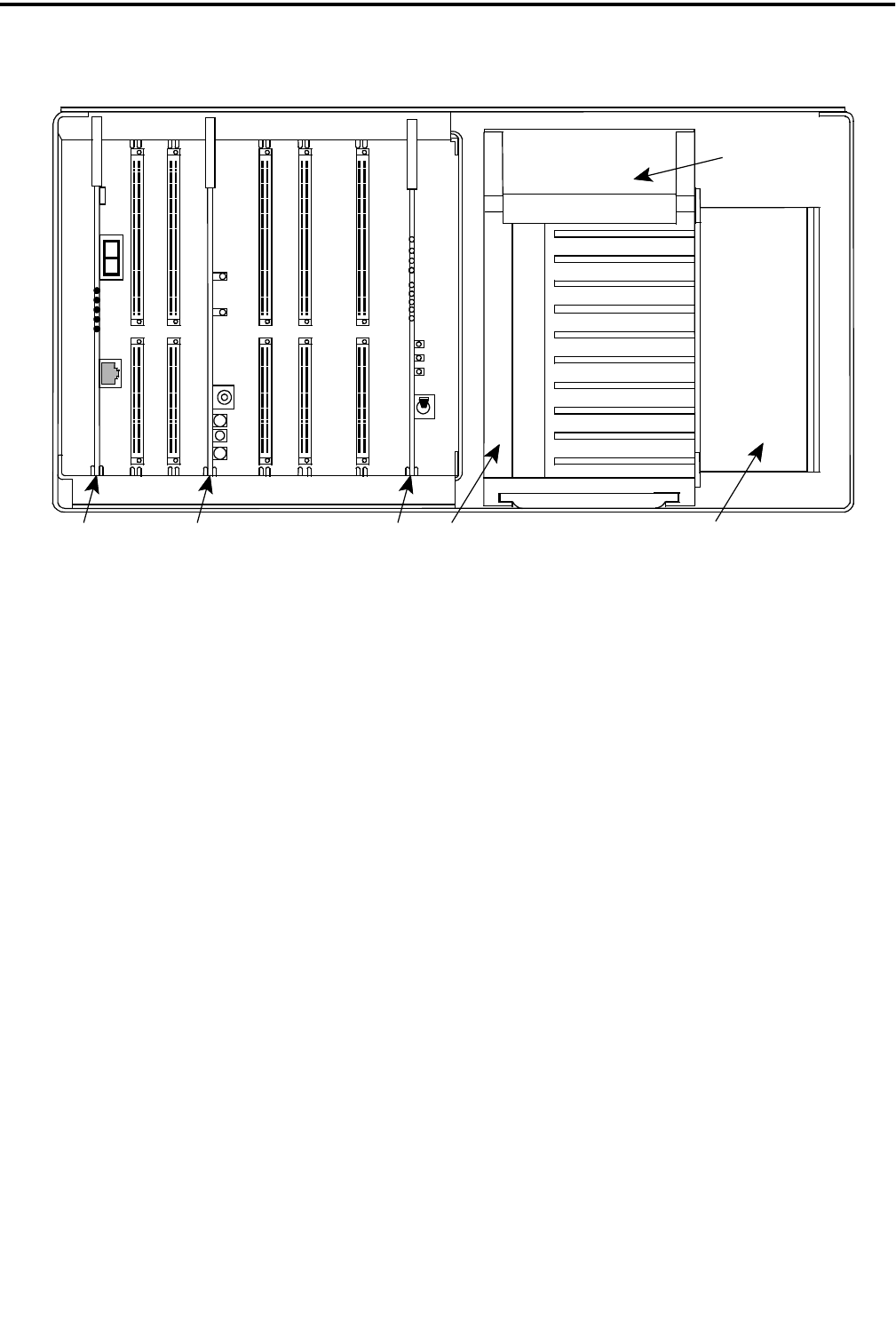
INTRODUCTION AND OPERATION
1-5 May 2000
Part No. 001-2008-204
Figure 1-4 REPEATER CARDS
IACMACMPC
J502
J501
J500
GRN
YEL
YEL
RED
RED
PROG
JACK
RESET
ON/OFF/VOL
LOCAL
MIC
SPKR
EXT SPKR
XMIT
MOBILE
SWITCH
HANG
CWID
+15V
GND
TP
J103
J100
GND
A D
LEVEL
R236
J102
J101
J104
J1
S1
CR1
CR2
CR4
DS1
S508
RF INTERFACE
BOARD
EXCITER/RECEIVER
PA
CR3
CR5
+5V
-5V
+15V
+15V ACC

INTRODUCTION AND OPERATION
1-6
May 2000
Part No. 001-2008-204
Table 1-2 ACTIVE REPEATER ALARMS
Alarm No. DS1 CR3 CR4 Definition
0
1
2
3
4
5
6
7
8
9
10
11
12
13
14
15
16
17
18
19
20
21
32
33
34
35
36
37
38
39
40
41
42
0
1
2
3
4
5
6
7
8
9
A
B
C
D
E
F
0
1
2
3
4
5
0
1
2
3
4
5
6
7
8
9
A
Off
Off
Off
Off
Off
Off
Off
Off
Off
Off
Off
Off
Off
Off
Off
Off
On
On
On
On
On
On
On
On
On
On
On
On
On
On
On
On
On
On
On
On
On
On
On
On
On
On
On
On
On
On
On
On
On
Off
Off
Off
Off
Off
Off
On
On
On
On
On
On
On
On
On
On
On
Test Mode
IAC input 1 Active
IAC input 2 Active
IAC input 3 Active
IAC input 4 Active
IAC input 5 Active
IAC input 6 Active
IAC input 7 Active
IAC input 8 Active
MAC Processor Alarm
HSDB Processor/Cable Alarm
IRDB Cable Alarm
RNT/CIM Channel Problem Alarm
TIC Processor Alarm
MMC Processor Alarm
VNC Alarm
AC Power Failure
Battery Power Failure
Power supply thermal sense
Fan 1 current out of specification
Fan 2 current out of specification
IAC mismatch
RF shutdown
RF Half Power Mode
Thermal sense in RF portion
RF Finals 1-2 power out failure
RF Finals 3-4 power out failure
RF VSWR Failure
Normal Synthesizer Tx Lock failure
Normal Synthesizer Rx Lock failure
HS Synthesizer Tx Lock failure
HS Synthesizer Rx Lock failure
RF Quarter Power Alarm

INTRODUCTION AND OPERATION
1-7 May 2000
Part No. 001-2008-204
1.12.2 MAIN AUDIO CARD (MAC)
Refer to Figure 1-4.
•External Speaker Jack
J104 provides repeater audio output to an external
speaker. The local volume control adjusts the volume
level of this speaker.
•Speaker/Microphone Jacks
J102 provides audio input from a microphone.
J101 provides the receive audio to the microphone.
•Local On/Off/Volume Control
R236 provides control of the receive audio output
to J101 and J104. Turning this control clockwise past
the detent applies voltage to the local audio amplifier.
•A D Level Test Point
J100 provides audio/data level output for test
level checks.
•Ground
J103 is connected to ground for test equipment
when monitoring test point J100.
1.12.3 INTERFACE ALARM CARD (IAC)
Refer to Figure 1-4.
•Voltage Test Output
J502 provides a +15V test point on the IAC.
•Ground
J501 is connected to ground for test equipment
when monitoring voltage test point J502.
•A D Level Test Point
J500 provides a test point to monitor audio and
data levels, AC fail and thermal sensor.
•Power Supply On/Off Switch
S508 turns the power supply DC voltages on and
off from the IAC in the front of the repeater.
•Power Indicator
CR501 indicates the +5V supply is at normal
level and applied to the IAC. CR524 indicates -5V
supply is at normal level and applied to the IAC.
CR523 indicates the +15V accessory supply is at nor-
mal level. CR525 indicates that the +15V supply is at
normal level and applied to the IAC.
•CWID Indicator
Indicates that the CW Identification is being
transmitted on the lowest-frequency repeater. The
CWID is a continuous-wave (CW) transmission of the
station call letters in Morse Code to satisfy the station
identification requirement. The CWID is programmed
into the repeater memory. This indicator also is used
when an alarm is transmitted with Morse code.
•Hang Indicator
Indicates that the hang word is being transmitted
by the repeater. This word is transmitted on calls in
which the channel is held for the duration of the call
and not just for the duration of the transmission. The
hang word tells the mobiles to stay on the same chan-
nel and not re-access the system when responding to a
call.
•Switch Call Indicator
Not used in the LTR repeater.
•Mobile Call Indicator
Mobile-to-repeater transmission in progress is
indicated by the Mobile Call Indicator.
•Xmit Indicator
This indicates that the repeater transmitter is
keyed by the logic.

INTRODUCTION AND OPERATION
1-8
May 2000
Part No. 001-2008-204
1.12.4 POWER SUPPLY
The 2000 Series Repeater Power Supply is a
quad output 800W supply with power factor correc-
tion. A battery back-up module, PN 023-2000-830,
can be added to the power supply to provide automatic
battery revert in the event of AC power failure (see
Section 2.5) The Battery Back-Up module charges the
batteries when AC is present at the power supply (see
Section 2.4 and 8.5).
1.13 REPEATER INFORMATION
1.13.1 INTRODUCTION
NOTE: The VIKING VX does not require a separate
LTR logic drawer.
The repeater model used in an LTR system is
determined by frequency range. 800 MHz systems
use the VIKING VX (-232/-234) or LTR 8000s, UHF
use 1010s, and VHF use 1100s. Repeaters operate on
a single frequency (one repeater is required for each
channel). The MPC in each repeater performs all con-
trol and signaling functions on that channel. Informa-
tion is exchanged between repeaters via a high-speed
data bus (modular cable). No system controller is
required.
Optional accessories, such as the Telephone
Interconnect Card (TIC) can be installed in the
repeater and the ID Validator drawer can be installed
in the repeater rack. Refer to Johnson LTR ID Valida-
tor Manual, Part No. 001-4408-501 and Johnson Tele-
phone Interconnect Card Manual, Part No. 004-2000-
370 for detailed information.
1.13.2 HOME REPEATERS
All mobiles have one of the site repeaters
assigned as its "Home" repeater. This is the repeater
from which it receives most of its control information.
When a mobile is not placing or receiving a call, it is
always monitoring its Home repeater to determine
which channel is free and if it is being called by
another mobile.
The Home repeater is always used to make a call
unless it is busy. When the Home repeater is busy,
any other repeater in the site may then be used. Up to
250 ID codes are assigned to each repeater. An ID
code and Home repeater number are the "address" of
the mobiles in the system. Therefore, up to 1250 sep-
arate addresses can be assigned in a 5-repeater system
and up to 5000 can be assigned in a 20-repeater sys-
tem. An ID code may be assigned to an individual
mobile or a group of mobiles as required.
1.13.3 INTER-REPEATER DATA COMMUNICA-
TION
Data communication between VIKING VX and
LTR repeaters at a site is via a high-speed data bus.
This bus cable is installed in a daisy-chain manner
between repeaters. If both VIKING VX and LTR
repeaters are located at a site, 20 repeaters can be
interconnected. Refer to Section 1.9 for information
on connecting the data bus.
1.13.4 MOBILE TRANSCEIVERS
The mobile and handheld transceivers used in an
LTR system must be compatible with the type of sig-
naling in use and also the frequency range.
1.14 REPEATER DATA BUS SIGNALING
1.14.1 GENERAL
A single-line serial data bus interconnects the
logic units of all the LTR repeaters at the site. The
first repeater powered on generates the synchroniza-
tion pulse that is used by all other repeaters to deter-
mine their time slot on the data bus. If all repeaters are
powered on at the same time, the lowest numbered
repeater generates the synchronization pulse. There
are 21 slots with 1-20 used for repeater reporting and
21 used by the ID Validator (see Section 1.14.3). The
time slot used by a repeater is determined by the num-
ber assigned to that repeater by the programming in
the MPC. Repeater 1 uses time slot 1, repeater 5 uses
time slot 5, and so on. The data rate on the repeater
data bus is 18,750 bits per second.
In its time slot, each repeater places information
on the data bus indicating its status. If a repeater is
not busy, only start bits appear in its slot. If a repeater
is busy, it places in its slot the Home repeater and ID
code of the mobile receiving the call on that repeater.
If a repeater number is unassigned, nothing appears in
that time slot.

INTRODUCTION AND OPERATION
1-9 May 2000
Part No. 001-2008-204
1.14.2 MOBILE DATA MESSAGE ORDER
Each repeater monitors all the time slots on the
repeater data bus. If it detects its number in another
time slot, it begins transmitting an additional data
message to its mobiles. This message tells mobiles
programmed to detect that ID code to go to that
repeater to receive a call. This additional message
continues for as long as the mobile is transmitting on
the other repeater.
The sequence of data messages transmitted on a
home repeater is as follows: Every third message is to
the mobile currently receiving a call on that repeater.
Then alternating between these messages are mes-
sages to its mobiles that have been trunked to other
repeaters. For example, assume that five different
mobiles on a five-repeater system are making calls. If
all have Repeater 1 as their home channel (not very
likely in actual practice), the data message order on
Repeater 1 is as follows: 1 2 3 1 4 5 1 2 3 and so on.
1.14.3 ID VALIDATOR OPERATION
If the ID Validator is used, it is programmed with
the status of up to all 5000 home repeater/ID code
combinations possible with a 20-channel system.
Each combination is programmed as either valid or
invalid. Information in the twenty time slots on the
repeater data bus is monitored. If an invalid home
repeater/ID code combination is detected, the ID Vali-
dator places in time slot 21 the number of the repeater
being used by the invalid mobile and also the ID code.
When a repeater detects its number in slot 21, it trans-
mits the turn-off code (31) to the mobile receiving the
call. That mobile then squelches and resumes moni-
toring its home channel. This effectively disables the
invalid mobile because it cannot talk to anyone.
When the turn-off code is sent, the repeater places
"21" in the repeater position of its time slot to indicate
to the ID validator that turn-off has occurred.

INTRODUCTION AND OPERATION
1-10
May 2000
Part No. 001-2008-204

INTRODUCTION AND OPERATION
1-11 May 2000
Part No. 001-2008-204
SPECIFICATIONS
GENERAL1
Frequency Range 806-824 MHz Receive, 851-869 MHz Transmit
Dimensions 9.125" H x 17" W x 20.9" D
AC Voltage/Frequency 100-240V AC/50-60 Hz
AC Current (Low Power) 0.40A (Standby), 1.7A (25W), 2.8A (75W)
AC Current (High Power) 0.40A (Standby), 3.8A (75W), 5.8A (175W)
AC Input Power (Low Power) 45W (Standby), 199W (25W), 328W (75W)
AC Input Power (High Power) 45W (Standby), 445W (75W), 680W (175W)
DC Current at 26.5V DC (Low Power) 5.2A (25W), 9.8A (75W)
DC Current at 26.5V DC (High Power) 11.5A (75W), 19.5A (175W)
Number of Channels 1 (Synthesized, programmable)
Channel Spacing 25 kHz
Channel Resolution 12.5 kHz
Temperature Range -30°C to +60°C (-22°F to +140°F)
Duty Cycle Continuous
FCC Type Acceptance ATH2422008, ATH2422008-1
FCC Compliance Parts 15, 90
RECEIVER
12 dB SINAD 0.35 µV
20 dB Quieting 0.50 µV
Signal Displacement Bandwidth ±2 kHz
Adjacent Channel Rejection -85 dB
Intermodulation Rejection -80 dB
Spurious & Image Rejection -90 dB
Audio Squelch Sensitivity 12 dB SINAD
Audio Response +1/-3 dB TIA
Audio Distortion Less than 3% at 0.5W/16 ohms
Local Audio Power 0.5W/16 ohms
Audio Sensitivity ±1.5 kHz
Hum & Noise Ratio -45 dB
Frequency Spread 6 MHz
Frequency Stability ±1 PPM -30°C to +60°C (-22°F to +140°F)
TRANSMITTER
RF Power Out (Low Power) 75W (Default setting), 25W (Variable Set Point)
RF Power Out (High Power) 175W (Default setting), 75W (Variable Set Point)
Spurious Emissions -90 dBc
Harmonic Emissions -90 dBc
Audio Deviation ±3.5 kHz
LTR Data Deviation ±1 kHz
CWID Deviation ±2 kHz
Repeat Deviation ±1.5 kHz
Audio Response +1/-3 dB TIA
Audio Distortion Less than 2%
Hum & Noise (TIA) -45 dB
Frequency Spread 6 MHz
Frequency Stability ±1 PPM -30°C to +60°C (-22°F to +140°F)
Emission Designators 14K0F3E, 16K0F3E, 14K0F3D, 16K0F3D, 14K0F1D,
16K0F1D
1. These general specifications are intended for reference and are subject to change without notice. Contact the Systems
Applications consultants for guaranteed or additional specifications.

INTRODUCTION AND OPERATION
1-12
May 2000
Part No. 001-2008-204

2-1 May 2000
Part No. 001-2008-204
INSTALLATION
SECTION 2 INSTALLATION
2.1 INTRODUCTION
Information in this section tells how to set up the
repeater for operation in an LTR system. It is assumed
that the repeater has been previously aligned at the
factory or as described in the alignment procedure in
Section 7.
Even though each repeater is thoroughly aligned
and tested at the factory, it is good practice to check
performance before it is placed in service. This
ensures that no damage occurred during shipment and
that the repeater is otherwise operating properly. Per-
formance testing is described in Sections 7.1, 7.2, 7.3
and 7.4.
2.1.1 SITE PREPARATION AND ANTENNA IN-
STALLATION
Site preparation and antenna installation are not
within the scope of this manual. Basic installation
requirements are discussed in the "Dealer Guide To
Site Preparation", Part No. 004-8000-100. Factory
installation is also available. Contact your Johnson
representative for more information.
2.2 ENVIRONMENT
The following conditions should be considered
when selecting a site for the Repeater.
Operating Temperature.
-30°C to +60°C (-22°F to +140°F).
Humidity.
Less than 95% relative humidity at 50°C.
Air Quality.
For equipment operating in a controlled environ-
ment with the Repeaters rack mounted, the airborne
particles must not exceed 30 µg/m3.
For equipment operating in an uncontrolled envi-
ronment with the Repeaters rack mounted, the air-
borne particles must not exceed 100 µg/m3.
NOTE: If the Repeater is installed in an area that ex-
ceeds these environmental conditions, the site should
be equipped with air filters to remove dust and dirt that
could cause the equipment to overheat. The cabinets
and filters should be placed on a maintainence sched-
ule.
When the repeaters are installed in an environ-
ment that contains small airborn particles, e.g. grain
dust or salt fog, the repeater cabinets need to be
sealed. A heat exchanger, i.e. air conditioner, is then
required to cool the cabinets. The air conditioners
must be suited for the environment. Each low power
repeater (75W) requires >1200 BTU/hr dissipation to
maintain exterior cabinet temperature. Each high
power (160W or 175W) requires >2100 BTU/hr dissi-
pation to maintaim exterior cabinet temperature.
2.3 VENTILATION
The RF modules and the power supply are
equipped with fans, controlled by thermostats, that
force air through the equipment for cooling. The air
flow is from the front to the back of the equipment.
This permits the Repeaters to be stacked or rack
mounted (see Figure 2-4). There are a few consider-
ations when installing Repeaters to provide adequate
air circulation.
1. The Repeaters should be mounted with a minimum
of 6 inches clearance between the front or back of
the cabinet for air flow. The power supply requires
a minimum of 18 inches at the back of the Repeater
for removal.
NOTE: Repeaters should not touch. Leave a mini-
mum of one empty screw hole (approximately 1/2")
between repeaters vertically especially for bottom
ventilation slots in high power repeaters.
•Cabinet enclosures must provide air vents for ade-
quate air circulation.
•Temperature and humidity must be considered
when several Repeaters are installed at a site. This
might require air conditioning the site.
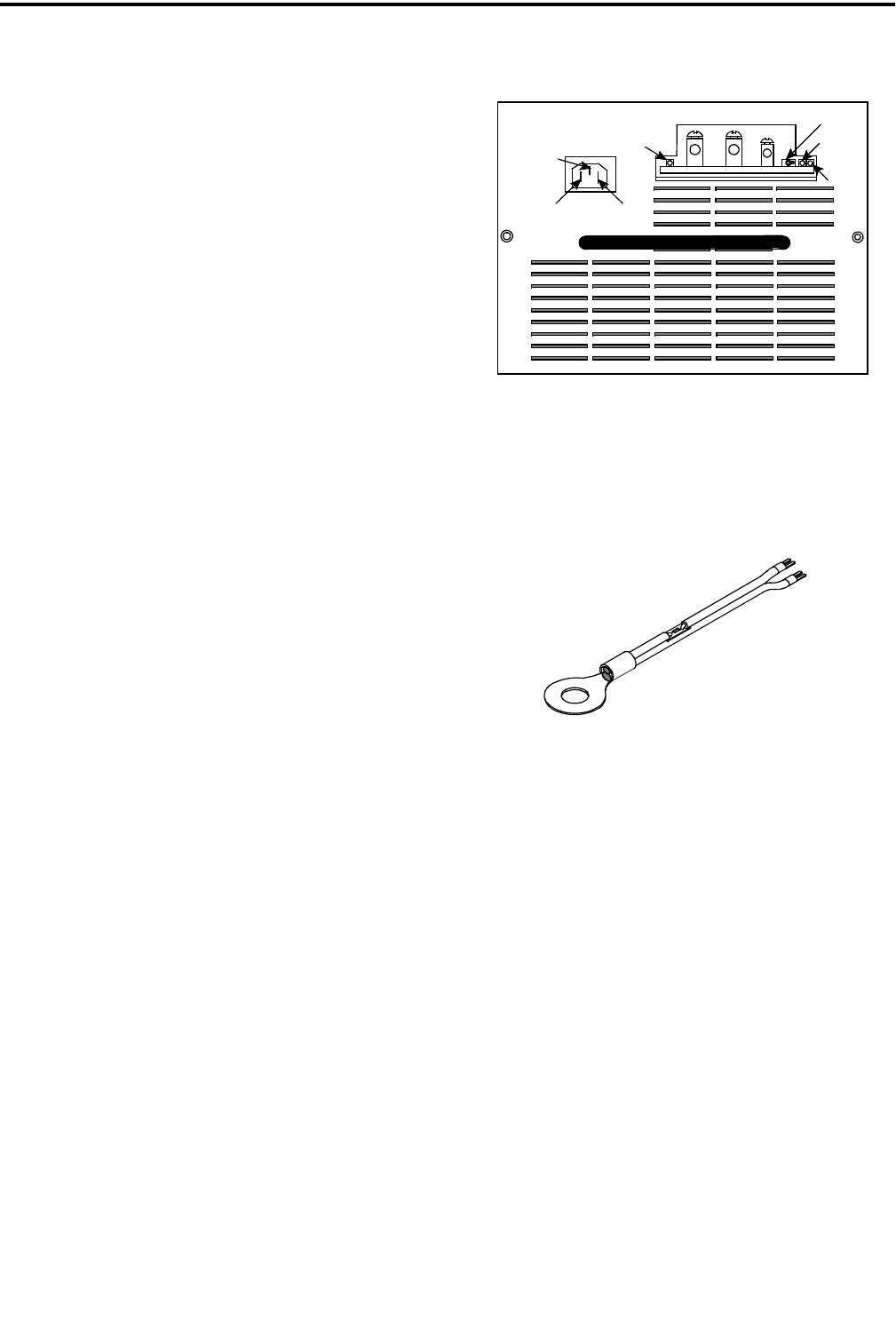
INSTALLATION
2-2
May 2000
Part No. 001-2008-204
2.4 AC POWER
The AC power source to the Johnson VIKING
VX Repeater can be 120V AC or 240V AC. Nothing
need be done to the power supply for 240V AC opera-
tion. However, a 240V AC outlet requires that the
120V AC power plug be replaced. A locking AC
power cord is provided for the supply.
The 120V AC cord is a standard 3-wire grounded
cord used with a standard AC wall outlet. The outlet
must be capable of supplying a maximum of 328W (-
232) or 680W (-234). With the nominal 120V AC
input, the source must supply 3A for each 75W
repeater or 6A for each 175W repeater and should be
protected by a circuit breaker. It is recommended that
all of the repeaters in a rack should not be on the same
breaker in order to provide one operational repeater in
the event a breaker trips. An AC surge protector is
recommended for all equipment.
Each Repeater requires an outlet, so for a 5-chan-
nel system, a minimum of 5 outlets is required. An
additional three outlets should be added for test equip-
ment. The outlets must be within 3 feet of each
Repeater cabinet. Future system expansion should be
considered when electrical work is being planned for
the initial system.
The VIKING VX Repeater power supply can be
equipped with an optional 24V DC back-up in the
event of AC power failure. Since the transmitter will
remain on full power, if desired, the DC power source
must have a current capability of about 15A per 75W
repeater (25A per 175W repeater) or 75A for 5-75W
repeaters (125A for 5-175W repeaters). The multi-
coupler requires another 0.5A for a total system
requirement at 24V DC of 75.5A for 75W repeaters
(125.5A for 175W repeaters).
2.5 BATTERY BACKUP
If the power supply is equipped with battery
backup, screw lugs are provided on the front of the
power supply for battery connections (see Figure 2-1).
A switch is provided for charging the battery or can be
off if a separate battery charger is used. A battery
temperature sensor connection is also provided. The
temperature sensor cable is shown in Figure 2-2. LED
indicators are provided to show Reverse Battery con-
nection, Charger On/Off and Battery Fault.
Figure 2-1 BATTERY BACKUP CONNECTOR
Figure 2-2 TEMPERATURE SENSOR CABLE
2.6 800W POWER SUPPLY
The power supply has four voltage output levels
(see Table 2-1). Each voltage is set to ±1% at +25°C
(+77°F). The output of this supply is capable or run-
ning any 2000 series repeater.
Each output is overload protected such that the
power supply current limits and automatically resets
when the overload is removed (see Table 2-1).
Each output is over voltage protected such that
the power supply shuts down when an over voltage
condition exists, usually when a component in the
supply has failed (see Table 2-2). The power supply
must be manually reset by toggling the Enable Line or
removing AC power for more than 10 seconds.
B- B+ TEMP ACTIVE
CHARGER
ON
CHARGER
FAULT
BATTERY
BATTERY
REVERSE
GROUND
EARTH
NEUTRAL
LINE
SWITCH
BATTERY
TEMP
TERMINAL
NEGATIVE
GND
BLK
WHT
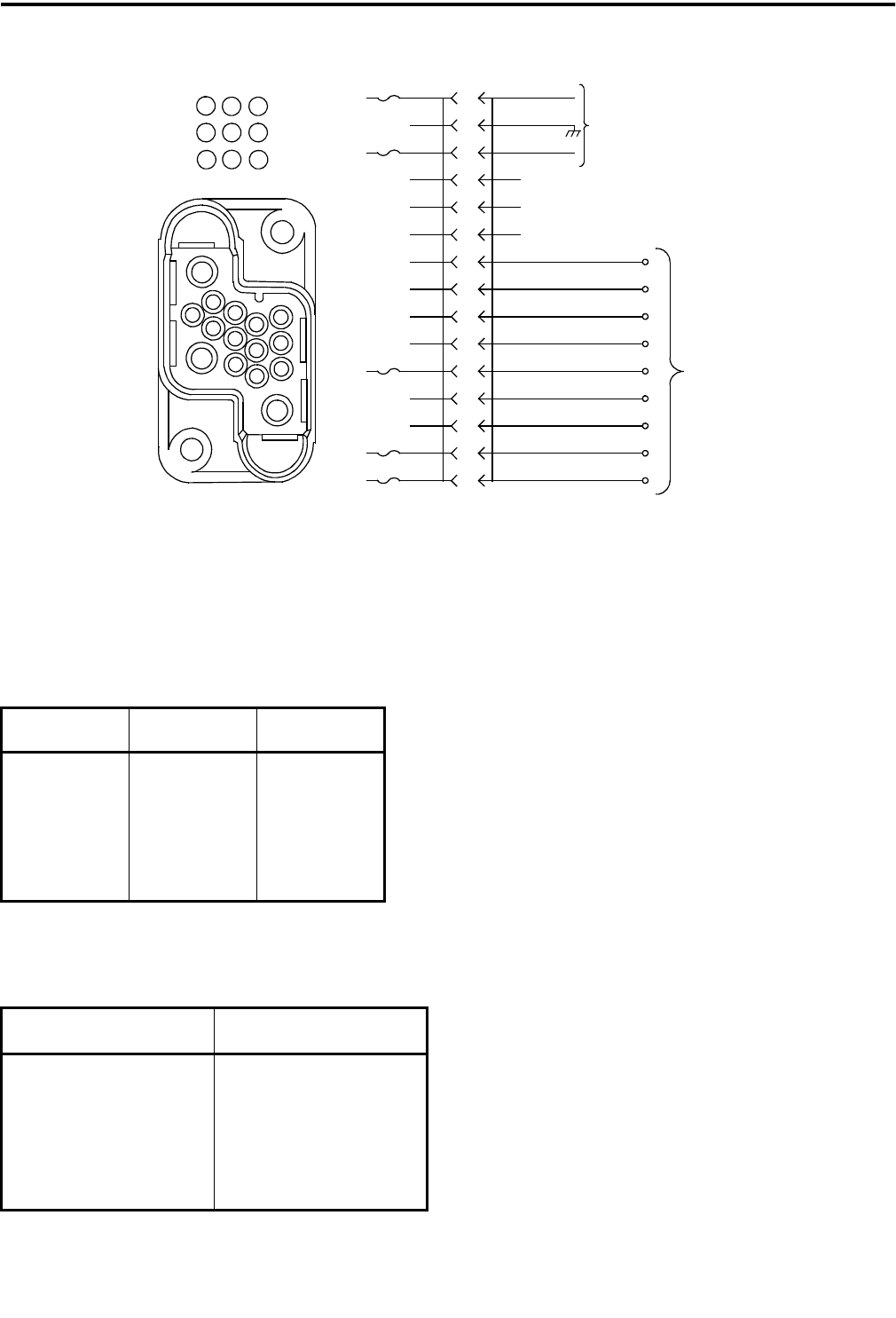
INSTALLATION
2-3 May 2000
Part No. 001-2008-204
Table 2-1 OUTPUT VOLTAGES
Voltage Current Wattage
+26.5V 22A 583W
+15V 5A 75W
+5.2V 5A 26W
-5V 1A 5W
Table 2-2 OVER VOLTAGE
Voltage Range
+26.5V +32V to +33V
+15V +16V to +18V
+5.2V +6V to +7V
-5V -6V to -7V
2.6.1 AC INPUT REQUIREMENTS
AC Input Voltage: 100-240V AC
Line Frequency: 50-60 Hz
AC In-rush: 60A maximum
Overall Efficiency: >70% at 100V AC
>80% at 240V AC
Lightning protection: 6kV for < 1ms
Power Factor: >0.97 at full load
Brown Out Voltage: 80V AC
Temperature -30°C - +60°C (full power)
Power factor correction per IEC555. The Power
supply has the following safety agency approvals
pending: UL1950, CSA22.2-950, TUV EN60950
(IEC950)
When the AC input voltage is below 90V AC, the
maximum output power is decreased to keep the input
current constant. If a battery back-up is installed, the
batteries take over when the AC input voltage falls
below 80V AC (dependant on power output).
The AC input connector is an IEC connector
equipped with a locking mechanism.
Figure 2-3 POWER CABLE CONNECTOR AND SCHEMATIC
9
7
12
11
10
8
6
5
4
3
2
1
A
B
C
J2
1
2
3
4
5
6
7
8
9
REPEATER
BACKPLANE
AC FAIL IN
POWER SWITCH
THERMAL SENSOR
+15V
N/C
N/C
-5V
TO
POWER HARNESS
GROUND
+15V
+5V
TO
RFIB
+26.5V
A
B
C
12
34
5
6
7
8
9
10
11
12
369
8
52
147
J2
BACKPLANE
N/C

INSTALLATION
2-4
May 2000
Part No. 001-2008-204
The operating temperature range is -30°C to
+60°C (-22°F to +140°F), i.e. the same as the repeater.
The fan is thermostatically controlled by the internal
temperature. When the internal heatsink temperature
reaches +45°C (113°F) the fan turns on. When the
heatsink temperature drops below +35°C (95°F) the
fan turns off. If the internal heatsink temperature
reaches +90°C (+194°F) the power supply turns off
until the heatsink temperature drops below +85°C
(+185°F). The over-temperature shutdown and restart
are automatic.
2.7 GROUNDING
CAUTION
PROPER SITE GROUNDING AND LIGHTNING
PROTECTION ARE VERY IMPORTANT TO PRE-
VENT PERMANENT DAMAGE TO THE REPEATER.
As in any fixed radio installation, measures
should be taken to reduce the possibility of lightning
damage to the Viking VX equipment. Proper ground-
ing eliminates shock hazard, protects against electro-
magnetic interference (EMI) and lightning.
Ground each piece of equipment separately. Do
not ground one piece of equipment by connecting it to
another grounded piece of equipment.
A good DC ground must be found or created at
the site. Rooftop site grounds can be researched
through the building management or architects. Tower
site grounds must be made with grounding rods. The
many techniques for providing adequate grounds for
towers and poles and for installing building ground
bus lines are beyond the scope of this manual. Refer
to National Electrical Code article 250 "Grounding
Techniques," article 800 "Communications Systems"
and follow local codes.
The ground bus should be routed to the floor area
within 5 feet of the system with a runner of 6 AWG or
larger solid copper wire or 8 AWG stranded copper
wire.
The outer conductor of each transmission line at
the point where it enters the building should be
grounded using 6 AWG or larger solid copper wire or
8 AWG stranded wire.
Secondary protection (other than grounding) pro-
vides the equipment protection against line transients
that result from lightning. There are two types of sec-
ondary protection, RF and Telephone Line. Use the
same wire sizes as specified for coaxial cables for any
ground connections required by the secondary protec-
tors.
•RF
An RF protector keeps any lightning strike to the
antenna feed line or tower from damaging the Repeat-
ers. Install this protection in-line with the combiner
and antenna feed line.
RF protectors are selected by calculating the
maximum instantaneous voltage at the output of the
combiner. Do this by using the following equation.
where:
VP = Voltage at the output of the combiner.
P = repeater output in watts
X= for VSWR=
1.05 1.10 : 1
1.09 1.20 : 1
1.13 1.30 : 1
1.17 1.40 : 1
1.20 1.50 : 1
1.30 1.86 : 1
Example: Repeater power output of 60W with a
VSWR of 1.3 : 1 (for this VSWR, X = 1.13):
VP = 87.52V
•Telephone Line
There are four types of protection suppressors for
telephone lines; Gas Tube, Silicon Avalanche Diode,
Metal Oxide Varistor and Hybrid.
The hybrid protector is ideal for Transcrypt Inter-
nation, Inc. equipment, and is strongly recommended.
A hybrid suppressor combines several forms of protec-
tion not available in just one type of device.
Vp 1.414 X() P50()()=
Vp 1.414 1.13()60 50()()=
Vp 1.59782 60 50()()=
Vp 1.59782 54.772256()=
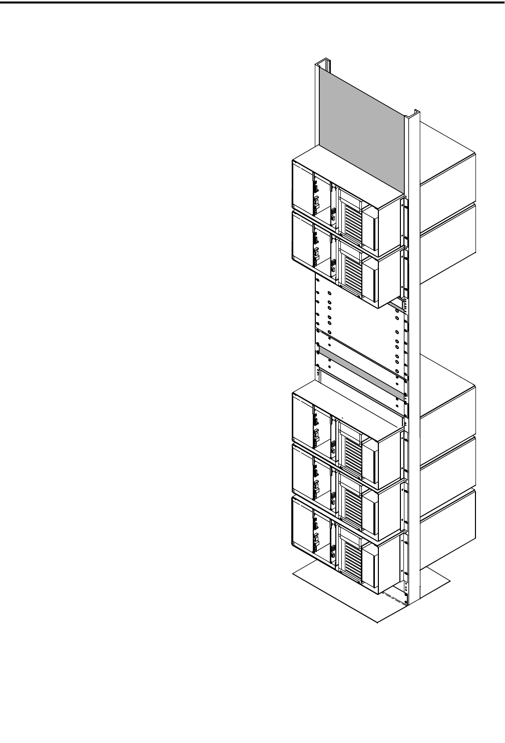
INSTALLATION
2-5 May 2000
Part No. 001-2008-204
For example, a high-speed diode reacts first,
clamping a voltage strike within 10 ns, a heavy duty
heat coil reacts next to reduce the remainder of the
current surge, and a high-powered three-element gas
tube fires, grounding Tip and Ring.
2.7.1 PROTECTION GUIDELINES
Follow these guidelines for grounding and light-
ning protection. Each Repeater installation site is dif-
ferent; all of these may not apply.
•Ensure that ground connections make good metal-
to-metal contact (grounding rod, grounding tray,
metal conduit) using #6 gauge solid wire or braided
wire straps.
•With surge protectors, ensure that ground wires go
directly to ground, and not through other equipment.
•Run the ground wire for RF coax protectors directly
to ground.
•With coax protectors, ensure maximum instanta-
neous voltage does not exceed the rated voltage.
•Do not run ground wires parallel to any other wiring
(e.g. a ground wire parallel to a telephone line),
except other ground wires.
•Double check all equipment for good ground and
that all connections are clean and secure.
2.8 UNPACKING AND INSPECTION
Transcrypt Internation, Inc. ships the Repeater
securely crated for transportation. When the Repeater
arrives, ensure the crates remain upright, especially if
storing the crates temporarily.
When unpacking the Repeater, check for any visi-
ble damage or problems caused by shipping. If there
is obvious damage from shipping mishaps, file claims
with the carrier. If there appears to be any damage
caused before shipping, file a claim with Transcrypt
Internation, Inc. Contact Customer Service for assis-
tance (see Section1.7). Figure 2-4 RACK MOUNTED REPEATERS
POWER STRIP
TX COMBINER
DUPLEXER
RX MULTICOUPLER
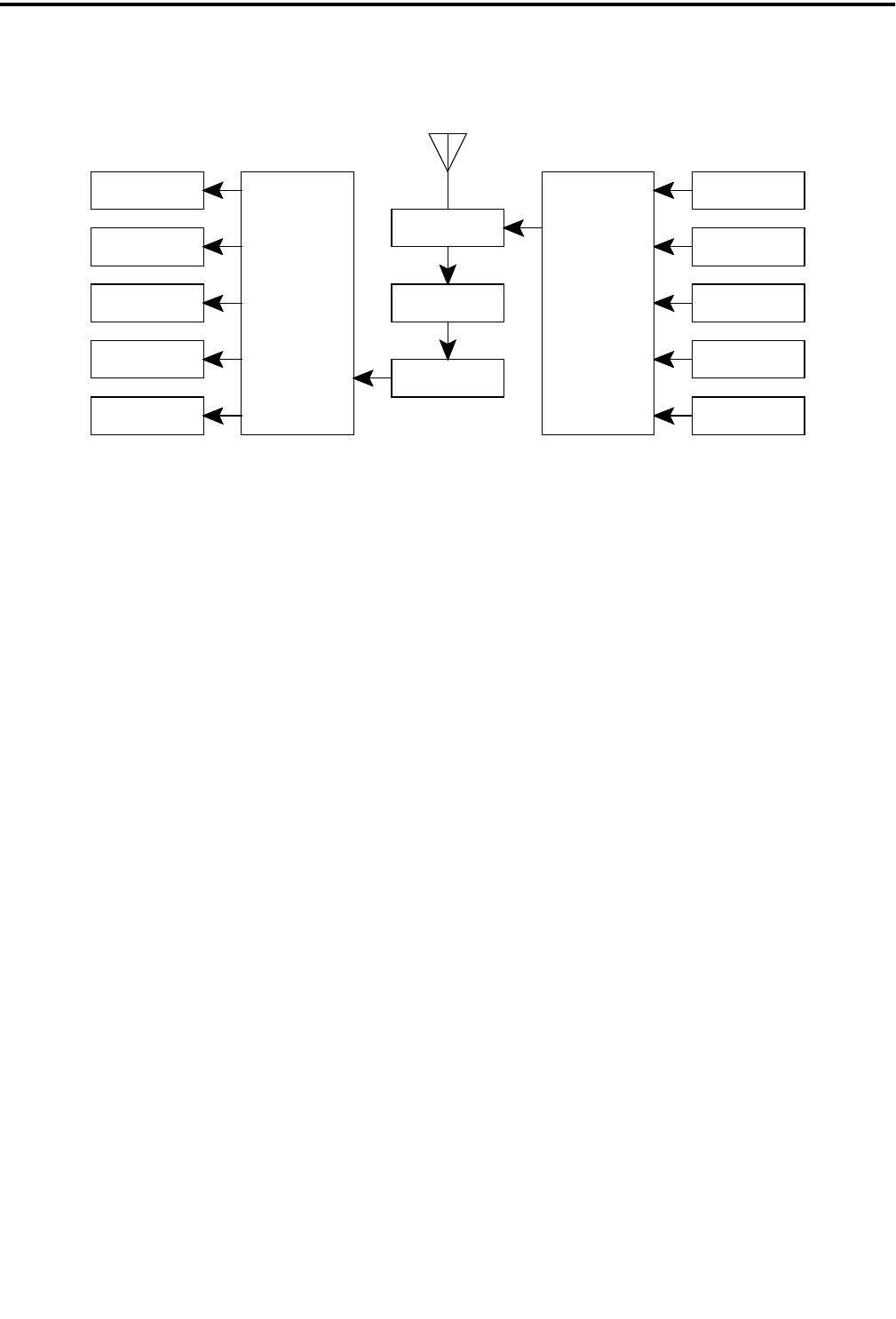
INSTALLATION
2-6
May 2000
Part No. 001-2008-204
If everything appears undamaged, remove the
Repeater equipment from the crate, using normal pre-
cautions for unpacking.
NOTE: Do not discard the packing materials. If you
must return an item; use the same packing materials
and methods (including static protective bags for cir-
cuit cards) to repack the equipment. You are responsi-
ble for proper repacking. Transcrypt Internation, Inc.
cannot be responsible for damage to equipment
caused by negligence.
NOTE: Repeaters should not touch, leave a minimum
of one empty screw hole (approximately 1/2") between
repeaters vertically especially for bottom ventilation
slots in high power repeaters.
NOTE: Each repeater should be grounded separately
by connecting a ground bus from the ground lug on
the back side of the RF module to the ground bar on
the rack (see Figure 2-8).
2.9 REPEATER DATA BUS INSTALLATION
VIKING VX repeaters with High Speed Data
Bus (HSDB) software Version 201 or earlier (refer-
ence U14 label) installed on the MPC board must use
the optional RJ-11 to BNC Adapter Module (see Table
1-1 and Figure 2-9) to connect the HSDB. Any
VIKING VX repeater (regardless of the HSDB soft-
ware version, see Section 4.5.4) that connects to a
HSDB that is also servicing LTR 8000/8900 repeaters,
other VIKING VX repeaters that use VIKING VNC
cards, or an ID Validator must also use the adapter
module. The BNC Adapter Module is installed on the
back of the VIKING VX repeater cabinet (see Figure
2-13 and Figure 2-14).
Systems constructed only with LTR VIKING VX
repeaters that have Version 202 or later HSDB soft-
ware ( see Section 4.5.4) and do not use VNC cards
can be connected directly to the HSDB from the RJ-11
jack on the back of the repeater.
2.9.1 MPC DATA BUS SWITCH SETTINGS
Switch settings on the MPC for the two types of
installations require S2 and S3 sections to be switched
as indicated in Figures 2-10 through 2-14.
2.9.2 MPC DATA BUS JUMPER SETTINGS
Refer to Figure 2-6 for crystal selection and
HSDB Code selections jumper placement. The
jumper on J5, pins 2-3 selects 12 MHz crystal for
LTR. The jumper on J4, pins 3-4 connects EPROM
U14, pin 27 (A14) to +5V for LTR single-ended 5V
data bus.
Figure 2-5 5-CHANNEL COMBINING SYSTEM
RECEIVER 1
RECEIVER 2
RECEIVER 3
RECEIVER 4
RECEIVER 5
RECEIVER
MULTICOUPLER
PREAMPLIFIER
FILTER
DUPLEXER
TRANSMITTER
COMBINER
TRANSMITTER 1
TRANSMITTER 2
TRANSMITTER 3
TRANSMITTER 4
TRANSMITTER 5
T/R ANTENNA
BANDPASS
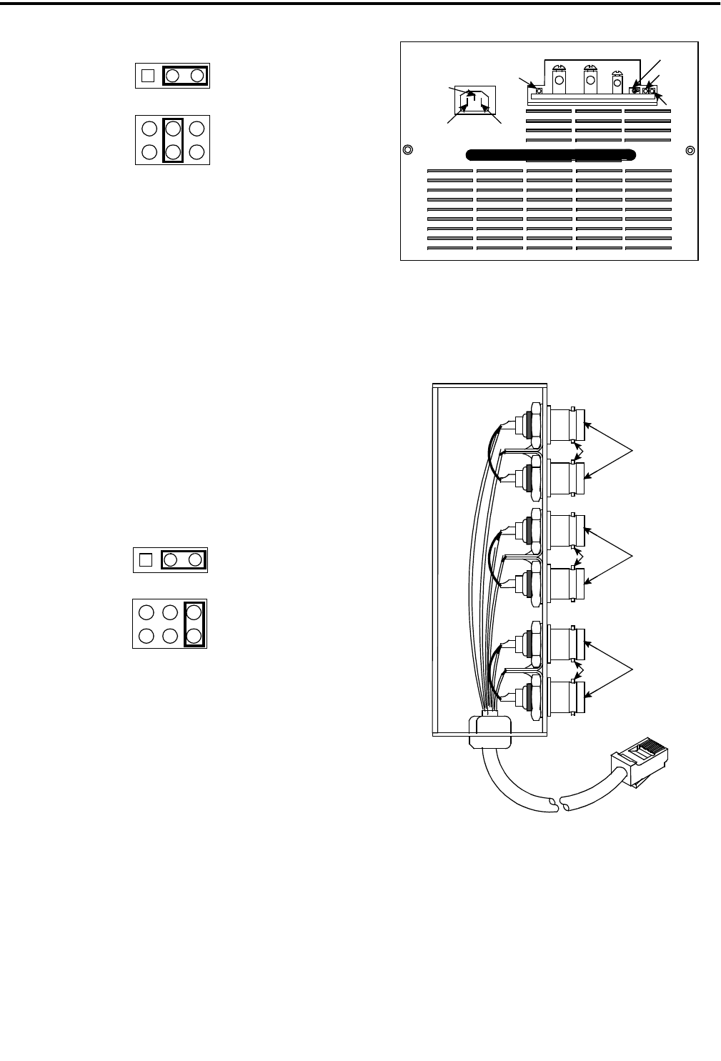
INSTALLATION
2-7 May 2000
Part No. 001-2008-204
Figure 2-6 RJ-11 TO BNC MPC JUMPERS
Jumper J4 must be placed with the following
guidelines (see Figure 2-6):
J4, pins 3-4 for operation with the RJ-11 to BNC
adapter module and mixed systems (2008 and 8000)
with any version of HSDB software.
J4, pins 3-4 for operation with the RJ-11 to BNC
adapter module with 2008 only systems with any
version of HSDB software.
J4, pins 5-6 for operation with the RJ-11 to RJ-11
cable with 2008 only systems with Version 202 or
later HSDB software.
Figure 2-7 RJ-11 TO RJ-11 MPC JUMPERS
2.10 CONNECTING RECEIVE AND TRANSMIT
ANTENNAS
Receive and Transmit antenna connector loca-
tions are shown in Figure 2-8. Although each trans-
mitter and receiver could be connected to a separate
antenna, this is usually not done because of the large
number of antennas required by a multiple repeater
installation. Therefore, an antenna combining system
is usually used. An example of a combining system
for a five-channel system is shown in Figure 2-5. The
amount of power loss introduced by a combiner
depends on the type of combiner used. If it has a loss
of 3 dB, power output to the antenna is reduced by
half.
Figure 2-8 ANTENNA CONNECTIONS
Figure 2-9 RJ-11 TO BNC ADAPTER MOD-
ULE
231J5
J4 1
2
3
46
5
HSDB CODE SELECTION
CRYSTAL SELECTION
23
1
J5
J4 1
2
3
46
5
HSDB CODE SELECTION
CRYSTAL SELECTION
B- B+ TEMP ACTIVE
CHARGER
ON
CHARGER
FAULT
BATTERY
BATTERY
REVERSE
GROUND
EARTH
NEUTRAL
LINE
SWITCH
PIN 2 BLK
PIN 3 RED
PIN 4 GRN
PIN 5 YEL
PIN 6 BLU
PIN 7 GRY
PIN 8 BRN
ORN
PIN 2
TLA+
PIN 1
TLA-
GRN
BLK
HSDB-
PIN 5
HSDB+
PIN 6
YEL
BLU
PIN 1 ORN
PIN 4
PIN 3
RED
IRDB- IRDB+
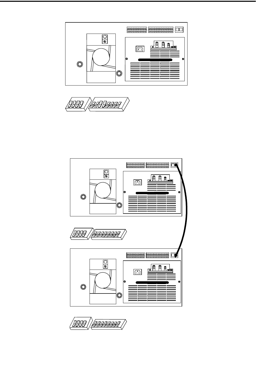
INSTALLATION
2-8
May 2000
Part No. 001-2008-204
Figure 2-10 SINGLE REPEATER INSTALLATION
Figure 2-11 TWO REPEATER INSTALLATION
ON21876543ON2143
S3 S2
ON
ON
S3 S2
2
18
7
65
43
2143
ON
ON
S3 S2
2
18
7
6
5
4
3
2143
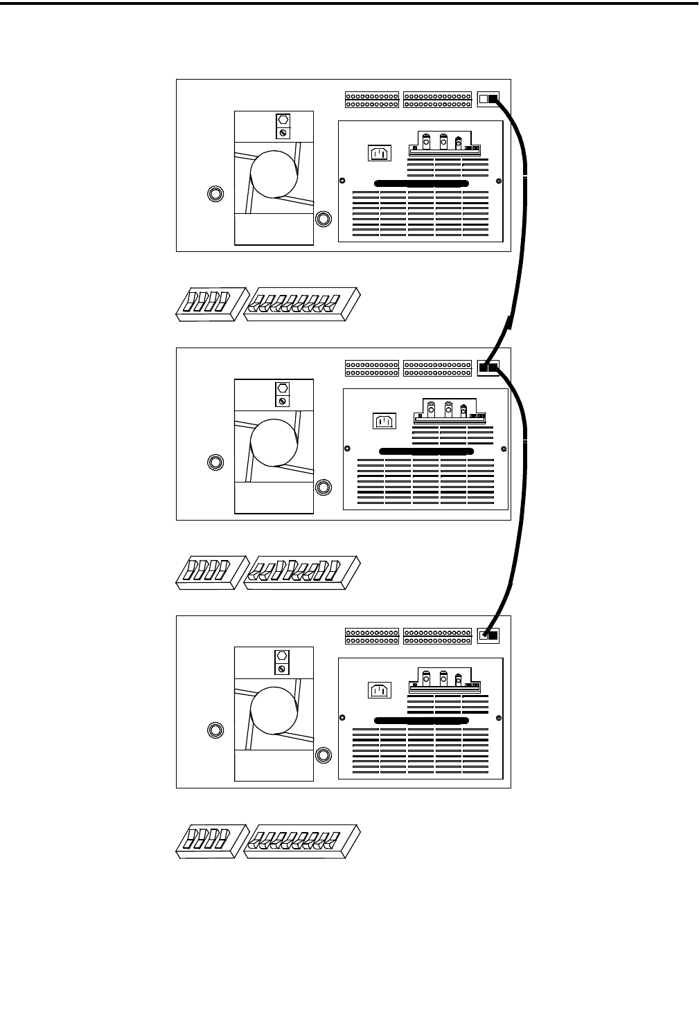
INSTALLATION
2-9 May 2000
Part No. 001-2008-204
Figure 2-12 THREE OR MORE REPEATERS INSTALLATION
ON
ON
S3 S2
2
187
6
5
4
3
2
14
3
ON
ON
S3 S2
2
18
7
6
5
4
3
2
143
ON
ON
S3 S2
2
187
6
5
43
2
14
3
END REPEATER
END REPEATER
MIDDLE REPEATERS
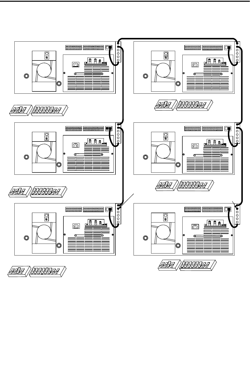
INSTALLATION
2-10
May 2000
Part No. 001-2008-204
Figure 2-13 MIXED VIKING VX REPEATER INSTALLATION
EARLIER HSDB VERSIONSHSDB VERSION 202 OR LATER
50 OHM
TERMINATION
50 OHM
TERMINATION
S2
S3
ON
S3 S2
2
143ON
2
187
6
5
43
ON
S3 S2
2
143ON
2
187
6
5
43
S2
S3
S2
S3
ON
S3 S2
2
143ON
2
187
6
5
4
3
S2
S3
ON
S3 S2
2
14
3ON
2
18
7
6
5
43
ON
S3 S2
2
14
3ON
2
18
7
6
5
43
ON
S3 S2
2
143ON
2
187
6
5
4
3
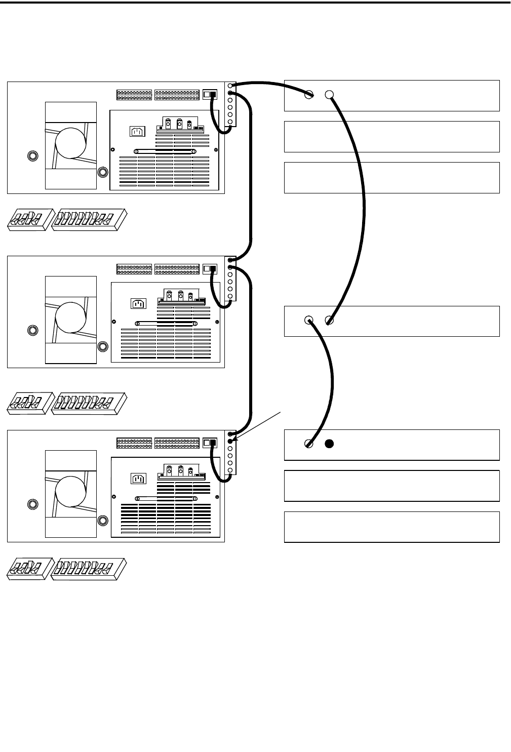
INSTALLATION
2-11 May 2000
Part No. 001-2008-204
Figure 2-14 MIXED VIKING VX AND CR1010 REPEATER INSTALLATION
ON
S3 S2
2
143
ON
S3 S2
2
14
3
ON
ON
S3 S2
2
18
7
6
5
4
3
2
14
3
50 OHM
TERMINATION
LOGIC
RECEIVER
EXCITER
50 OHM
TERMINATION
ID VALIDATOR
LOGIC
RECEIVER
EXCITER
OPTIONAL
ON
2
18
7
6
5
4
3
ON
2
187
6
5
4
3

INSTALLATION
2-12
May 2000
Part No. 001-2008-204

3-1 May 2000
Part No. 001-2008-204
SOFTWARE
SECTION 3 SOFTWARE
3.1 INTRODUCTION
The Johnson Summit QX Repeater Program on
3.5 inch disk, Part No. 023-9998-297, uses an IBM
personal computer to program the EEPROM Memory
in the Main Processor Card (MPC). To lessen the
chance of programming errors and simplify operation,
the program uses yes/no questions or toggles through
the available responses.
The computer is connected directly from the
serial card to the MPC. The interconnect cables used
are shown in Figure 4-30. The DB-9 to 8-pin modular
adapter is connected to the serial port of the computer
and an interconnect cable connects the adapter to the
MPC.
NOTE: These connections are for the IBM computer
and may differ from an IBM compatible. In which
case, consult the manuals for your computer for serial
card outputs and connections.
3.1.1 HOW TO USE THIS MANUAL
This manual introduces the program and illus-
trates how to use the features. This manual is orga-
nized to easily find programming information with the
Table of Contents, Index and Parameter Tables for the
responses required for programming.
Graphic reproductions of the screens are shown
for reference. Adjacent to the screens are tables to
provide the parameters, available responses and a brief
description of the parameter. It is not the intent of this
manual to teach computer operation, but to allow the
user to become familiar with the available screens and
the responses without having to be at the computer.
3.1.2 GETTING STARTED
NOTE: Before starting you should already know
how to start MS-DOS, format and make backup cop-
ies of disks, copy and delete files, and run programs.
If you are unfamiliar with any of these actions, refer to
the MS-DOS manual for your computer for more
information (see Section 5).
Follow the computer instructions for loading the
disk. The MS-DOS Revision 2.0 or later operating
system is needed to run the programs. The computer
needs to have RS-232C capability, for example, the
Serial Card in slot "COM1" or "COM2".
3.1.3 COMPUTER DESCRIPTION
The programming software is designed to run on
an IBM PC or compatible computer that meet the fol-
lowing minimum requirements.
•One 3.5" high density disk drive
•640K of memory
•MS-DOS version 2.0 or higher
•One serial port
•Monochrome or color monitor and video card
Although the program uses color to highlight cer-
tain areas on the screen, a monochrome (black and
white) monitor or LCD laptop also provide satisfac-
tory operation. Most video formats such as EGA and
VGA are supported. A serial port is required to con-
nect the repeater to the computer. This port is standard
with most computers.
The cables from the repeater to the computer are
not included. With most computers, the adapter-to-
computer cable is a standard DB-25 M-F cable, PN
023-5800-017, (the male connector plugs into the
adapter). If your computer requires a male connector,
a male-to-male cable is also available, PN 023-5800-
016. The cable from the adapter to the repeater has a
DB-9 to 8-pin connector (see Figure 4-30).
3.1.4 EEPROM DATA STORAGE
The data programmed into the MPC is stored by
an EEPROM memory. Since this type of device is
nonvolatile, data is stored indefinitely without the
need for a constant power supply. A repeater can be
removed from the site or even stored indefinitely with-

SOFTWARE
3-2
May 2000
Part No. 001-2008-204
out affecting programming. Since EEPROM memory
is also reprogrammable, a new device is not needed if
programming is changed.
3.1.5 COMMAND LINE OPTIONS
•Help
To show all options available from the command
line type: /h or /?. Either ’/’ or ’-’ can be used. For
example: 2000pgmr /h
The options can be entered in any order.
For example: 2000pgmr /d /b /c
•COM Port
The Johnson programming software defaults to
serial port COM1. However, if this port is already in
use, the software can be reconfigured to use serial port
COM2. To do this, use one of the following methods:
1. When running the compiled (.EXE) version, type /
c2 on the command line after the program name.
For example: 2000pgmr /c2 or -c2
2. Select COM port from Utilities heading.
BAUD RATE
The software defaults to 9600 baud, however this
rate can be changed. To do this from the command
line, type /bxxxx (xxxx = baud rate).
For example: 2000pgmr /b or -b
NOTE: When the baud rate is changed on the com-
mand line the baud rate jumpers on J3 in the MPC
must also be changed to the same baud rate (see Sec-
tion 6.10.8).
DEMO MODE
To view the screens for Read Setup Parms and
Write Setup Parms from the Transfer menu when a
repeater is not connected to the computer this option is
used. Normally these screens are not available with-
out a repeater connected. To do this from the com-
mand line, type: /d or -d.
For example: 2000pgmr /d
3.1.6 COLOR OR MONOCHROME OPERATION
The programming software utilizes color for a
color monitor and video card. However, with LCD-
type displays, this may make some information hard
to read because the contrast is poor. To improve con-
trast, a monochrome mode can be selected in the dis-
play mode from Utilities heading.
3.2 REPEATER PROGRAM SOFTWARE
3.2.1 INSTALLING THE SOFTWARE
When you receive the programming software,
make a backup copy and store the master in a safe
place. Copy the distribution disks using DOS DISK-
COPY command. For example, type:
DISKCOPY A: A: (single floppy drive)
or
DISKCOPY A: B: or C: (multi-drive systems).
If you have a hard disk drive, you may want to
create one or more separate directories for transceiver
programming and then transfer the program disk files
to those directories. To create a new directory, use the
MKDIR command. For example, to create directory
RADIOPRG, type:
MKDIR \RADIOPRG.
Then to make the new directory the current directory,
use the CHDIR command. For example, to change to
the \RADIOPRG directory, type
CHDIR \RADIOPRG.
To copy all files from a floppy disk in drive A: to this
directory, type:
COPY A:*.*
If you have a single floppy drive and no hard disk
drive, you need to create programming disks. The
reason for this is that there is not adequate space on
the backup disk(s) for storing radio files. If your com-
puter has dual floppy disk drives, the backup disk can
be placed in one drive and then the radio files stored
on a disk in the second drive.

SOFTWARE
3-3 May 2000
Part No. 001-2008-204
To make a programming disk, format a blank disk
using FORMAT B: or FORMAT B: /S (use "/S" if it
must be a bootable disk). Then copy the required pro-
gram file or files to the programming disk. To do this,
type COPY A:(filename.ext) B:(filename.ext). For
example, to copy the file 2000pgm2.exe from drive A
to drive B, type
COPY A:2000pgm2.exe B:2000pgm2.exe
This procedure works for either single or dual drive
computers. Refer to your computer reference manual
for more information on these DOS commands.
The programming software is shipped in a com-
pressed format. The name of the compressed file is
2000pgm2.exe and it extracts the following files so the
program can be used on a PC.
2000PGMR.EXE 480K
2000PGMR.HLP 42K
TESTM8L.HLP 2K
2000PGMR.LNF 173K
TESTM8H.LNF 11K
TESTM8L.LNF 225K
TESTM9H.LNF 11K
TESTM9L.LNF 208K
TESTT8L.LNF 53K
TESTT9L.LNF 51K
The 2000PGM2.EXE file is self extracting which
means that the files extract automatically when exe-
cuted. To extract these files so the program can be
used, first make the current directory the destination
directory for these files. For example, to make it the
\RADIOPRG directory on drive C: (if not the current
directory), type C: (Return) and then CD \RADIOPRG
as just described. To make it the disk in drive B:, sim-
ply type B:. Then insert the program disk in drive A:
and type A:2000PGM2 (or B: 2000PRM2 if drive B:
is being used). The program files are automatically
extracted into the current directory or disk.
3.2.2 MINIMUM FREE MEMORY REQUIRED
Approximately 525K of free conventional mem-
ory is required to run this program (use the CHKSK or
MEM command to display the amount of free mem-
ory). If you have at least 640K of memory and not
enough is available, there may be other programs that
are also being loaded into conventional memory. Con-
tact Customer Service for information on how these
programs can be moved or disabled to make more
space available.
3.3 REPEATER PROGRAMMER
When the program is loaded into the computer
and executed, the menu shows the files available from
the directory. The program is used to create, edit,
transfer and receive the repeater and channel parame-
ters described in Section 5.
I M P O R T A N T
The commands and displays referred to in this manual
are for the IBM PC and may differ from IBM compati-
ble. Refer to the computer’s operating system manual
for command explanations.
3.3.1 PROGRAM FILES
The files that appear in the program directory are
needed for program operation.
3.4 ALIGNMENT SOFTWARE
The software for the Summit QX repeater pro-
grams the MPC to open and close the audio/data gates
necessary for the alignment selected from the Test-Full
Repeater menu. Under the menu heading Test are the
alignment procedures for the PA (see Section 7.3),
Receiver (see Section 7.1), Exciter (see Section 7.2)
and overall Full Repeater (see Section 7.5) including
the MAC card (see Figure 3-1).
Figure 3-1 REPEATER TEST MENU
Refer to Section 7 for alignment procedures as
shown in the program, alignment points diagrams and
test setup diagrams.
File Edit Transfer Hardware Test Utilities
PA
Receiver
Exciter
RNT Interface
Full Rptr/Station
Telephone Interface
VNC Interface

SOFTWARE
3-4
May 2000
Part No. 001-2008-204
3.5 HELP F1
Help screens are available for most parameters
and options in this program. Whenever a parameter or
options clarification is needed, press F1 and if a help
screen is available it will pop-up on the screen. Press
Escape <ESC> to exit the pop-up screen.
Figure 3-2 PROGRAMMING FLOWCHART
Save As
DOS Shell
FILE
HELP - F1
Load
Save
Quit ALT X
Select Repeater
Alarm Configuration
EDIT
Setup Parameters F4
Delete Repeater
Repeater Type
HSDB Monitor
RX/TX Data
HARDWARE TTY Terminal
RF Data
TRANSFER Read Setup Parms F5
Write Setup Parms F6
Mode Select
Revisions
PA
Receiver
Exciter
TEST
RNT Interface
Full Rptr/Station
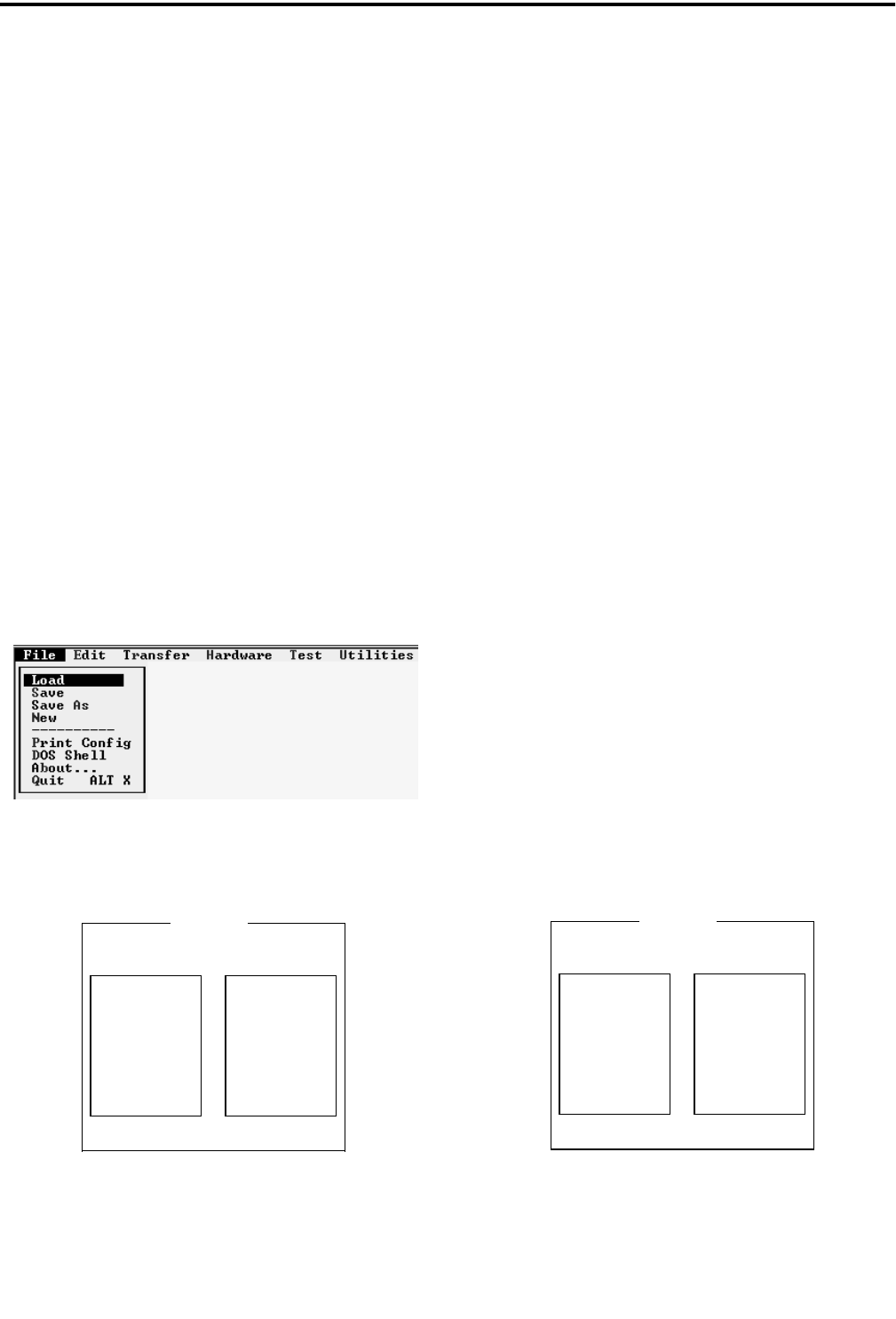
4-1 May 2000
Part No. 001-2008-204
PULL DOWN MENUS
SECTION 4 PULL DOWN MENUS
4.1 MENU DISPLAYS
The menus available are listed at the top of the
screen (see Figure 3-2). Move the cursor with the
arrow keys to highlight the menu name. Press Enter to
view the menu and the arrow keys to scroll through
the menu. Call up the highlighted selection by press-
ing Enter.
4.2 FILE MENU
This menu manipulates new or existing files into
directories and saves files to be called up at another
time.
Figure 4-1 FILE MENU
Figure 4-2 LOAD FILE
4.2.1 LOAD
Load reads information from a stored file. The
program requests the filename to be loaded into the
buffer. The filename from a disk can be entered in the
highlighted area. Then move the cursor down with the
arrow key and highlight "Ok" and press Enter. To
select an existing file, use the arrow keys to move
down the menu list and press Enter when the high-
lighted filename is the file to load.
4.2.2 SAVE
This saves the edited version of an existing file
loaded in the buffer under the same filename in the
directory and deletes the old file. It loads a new file
created in the Edit menu into the directory.
4.2.3 SAVE AS
This saves the edited version of an existing file
loaded in the buffer under a new filename or gives a
new file created in the Edit menu a filename.
Figure 4-3 SAVE FILE
Dir c:\example\file\load
..\
tmp\
Load File
Ok Cancel
File *.qx
file1.qx
Dir c:\example\file\load
..\
tmp\
Ok Cancel
Save File
File *.qx
test.qx

PULL DOWN MENUS
4-2 May 2000
Part No. 001-2008-204
4.2.4 NEW
This menu selection erases all Site and Repeater
information in the programmer and loads factory
defaults. If the current data has been changed, select-
ing File -> New provides the opportunity to save the
data before loading the defaults.
4.2.5 PRINT REPEATER CONFIGURATION
Select the destination for the configurations.
Printer - Prints to printer connected to PC.
File - Writes printable test to selected filename.
Select which repeater data will be printed.
All Repeaters - Prints the data for all valid
repeaters.
Single Repeater - Prints the data for the entered
repeater number.
NOTE: A list of valid repeaters can be seen under the Edit-
Select Repeater menu selection.
4.2.6 DOS SHELL
DOS shell temporarily suspends the program and
returns to DOS. Directories and other DOS com-
mands can be performed. To return to the program
from DOS, type EXIT and press Enter.
4.2.7 QUIT (ALT X)
Quit exits the repeater program and returns to
DOS. Save all files before exiting the repeater pro-
gram.
Figure 4-4 EDIT PROGRAMMING FLOWCHART
Repeater Number
Channel Number
Standalone
CWID Time
CWID Message
Local Mic ID
Test Mode ID
Default
Repeater Number
Input Alarms
Output Alarms
Cross Reference
Input Type Selection
Output Type Selection
Select Repeater
Alarm Configuration
EDIT
Setup Parameters F4
Alarm Cross Reference Selection
Delete Repeater
Repeater Type
Power Source
RF Power Level
Multi-Net
LTR
Universal Station
Frequency Band
Power Level
75W
800 MHz
800 MHz (-12.5 kHz)
900 MHz
Paging
Repeater Type
IAC Type
8 I/O IAC
4 I/O IAC
TELCO Network Type
Area
Data Modem
Telephone Access Parameters
Telephone Interface
TIC Calibration Data
175W

PULL DOWN MENUS
4-3 May 2000
Part No. 001-2008-204
4.3 EDIT
Figure 4-5 EDIT MENU
This menu is used to create new files and set or
change the repeater operating parameters. The file-
name for the repeaters in this file is shown in the
lower left corner of the screen.
4.3.1 SETUP PARAMETERS
First see Section 4.3.4 to select repeater type to
setup LTR Parameters. This menu programs the
repeater parameters and options of each repeater at a
site. Table 5-1 lists the parameters that are set by this
screen (see Figure 5-1) and gives a brief description of
each.
NOTE: The parameters are shown in the lower left of
the pop-up screen for reference.
•Repeater Number
Each repeater is programmed with a repeater
number from 1-20. Make sure that this number agrees
with the Home repeater number programmed in the
mobiles assigned to this repeater.
•Channel Number
Each repeater is programmed with a channel
number (1-920).
NOTE: Repeater program channel numbers 1-599
increment in 25 kHz steps. Program channel num-
bers 600-920 increment in 12.5 kHz steps. See Appen-
dix A to determine the correct operating frequency.
•Telco Network Type
None is used for LTR system repeaters.
•Area
This is the same as the area bit used when pro-
gramming the mobiles. This bit is usually "0".
•Sync Repeater
None is used for LTR system repeaters.
•Stand Alone
Select if the repeater is not connected to addi-
tional repeaters via the high speed data bus.
•ID Validator (Not applicable at this time.)
•CWID Time
The time interval between transmission of the
repeater’s CWID message.
•CWID Message
FCC regulations require that the station call let-
ters be transmitted periodically on the lowest- fre-
quency repeater in the system and disabled on all the
others. Morse code is used to encode these letters/
numbers for continuous-wave (CW) transmission (15
characters/numbers UPPER CASE).
•Local Mic ID
The local microphone connected to the MAC
jack is assigned a Group ID for transmitting when the
local microphone PTT is active. This allows the
Repeater to operate as a base station.
•Test Mode ID
This is the Group ID transmitted when the
Repeater is in Test Mode. Mobiles with the same
Group ID can communicate with the Repeater in Test
Mode.
•RF Power Level
This is the default power level. Enter the power
level for transmit power.
NOTE: This is not the actual power out level. Other
factors must be considered for true power out.
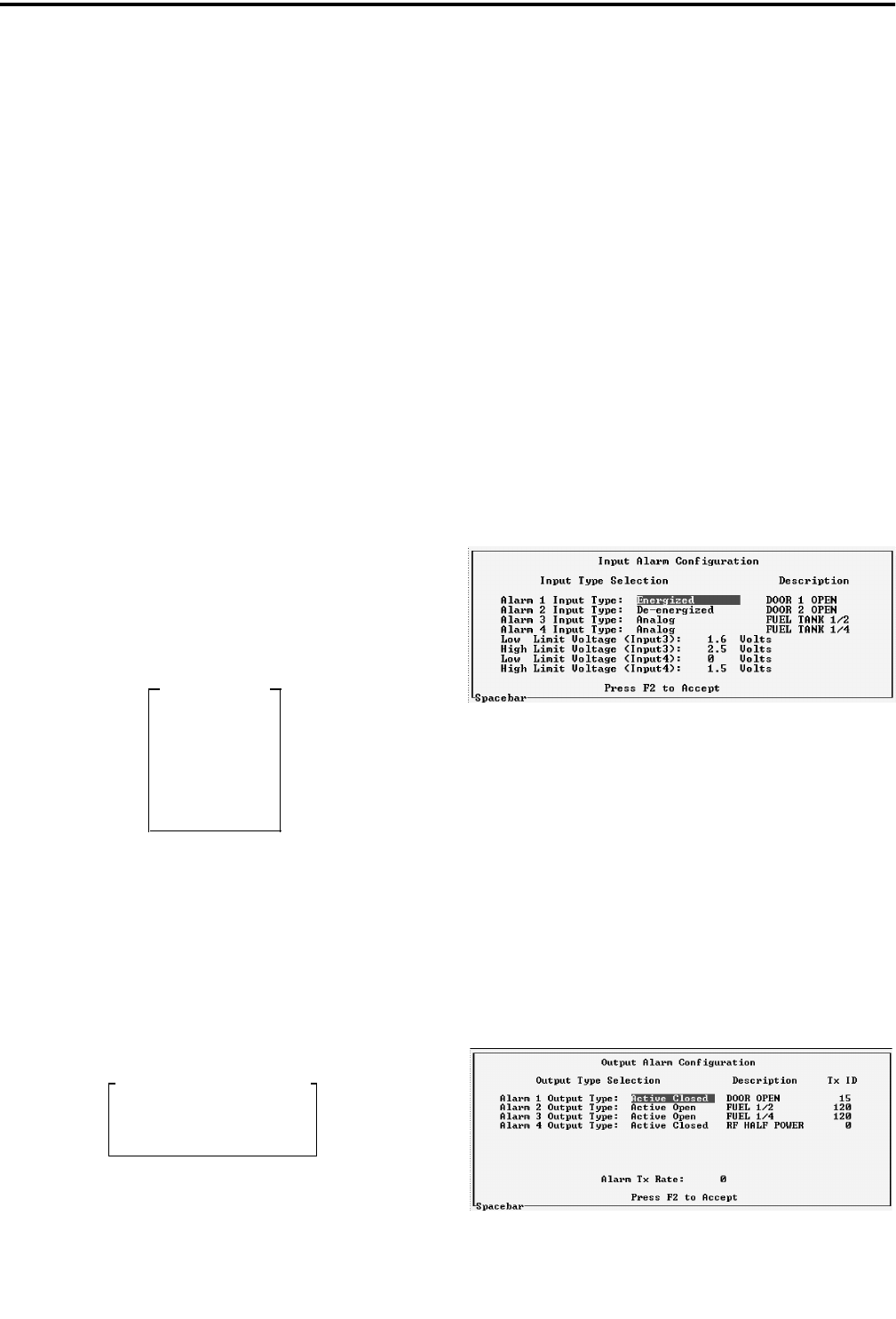
PULL DOWN MENUS
4-4
May 2000
Part No. 001-2008-204
•Power Source
This indicates the primary power source for the
Repeater (AC/DC). If AC is selected and Battery
Backup is installed, the transmitter goes to half rated
power (max.) when AC fails. If DC is selected and
AC fails, power output is unchanged.
•Paging
This indicates if there is an optional paging termi-
nal connected to the repeater. This option is not com-
patible with the LTR Data Modem, TIC or VNC
options.
•Data Modem
This is selected if the Data Modem option is
installed. This option is not compatible with Paging,
TIC, or VNC.
4.3.2 SELECT REPEATER
Select the repeater number to be programmed or
edited from the pop-up menu (see Figure 4-6). Move
the cursor with the arrow keys to highlight the repeater
number and press Enter.
Figure 4-6 REPEATER LIST
4.3.3 ALARM CONFIGURATION
This programs the input alarm (see Figure 4-8)
and output alarm (see Figure 4-9) configurations and
provides a cross reference screen.
Figure 4-7 ALARM CONFIGURATION
Use the arrow keys to move down the list. Use
the Space bar to toggle through the parameters: Dis-
abled, Active Low, Active High, for each alarm.
•Input Alarms
There are four input alarms that can be activated
by external devices (see Section 6.12). These inputs
can be disabled, energized or de-energized. Alarms 3
and 4 can also be analog input.
If the input is disabled, the input alarm line is
inactive. When energized and current flow is detected,
the alarm is activated. When de-energized and no cur-
rent flow is detected, the alarm is activated. Analog
inputs provide a detection of an analog input out of
limit condition. Select the Low and High Limit pair to
trip an Analog Input Alarm. The High Limit must be
greater in value than the Low Limit (0.0V-5.0V in
0.1V steps).
Figure 4-8 INPUT ALARMS
•Output Type Selection
Select the operation of the Output Alarm. The
available types are:
Active Open - An active alarm opens (no contact)
the output lines.
Active Closed - An active alarm closes (contact)
the output lines.
Figure 4-9 OUTPUT ALARMS
Repeater List
default
Rptr 1
-------
-------
-------
Rptr 30
Select Which Alarms To Edit
Input Alarms
Output Alarms
Cross Reference
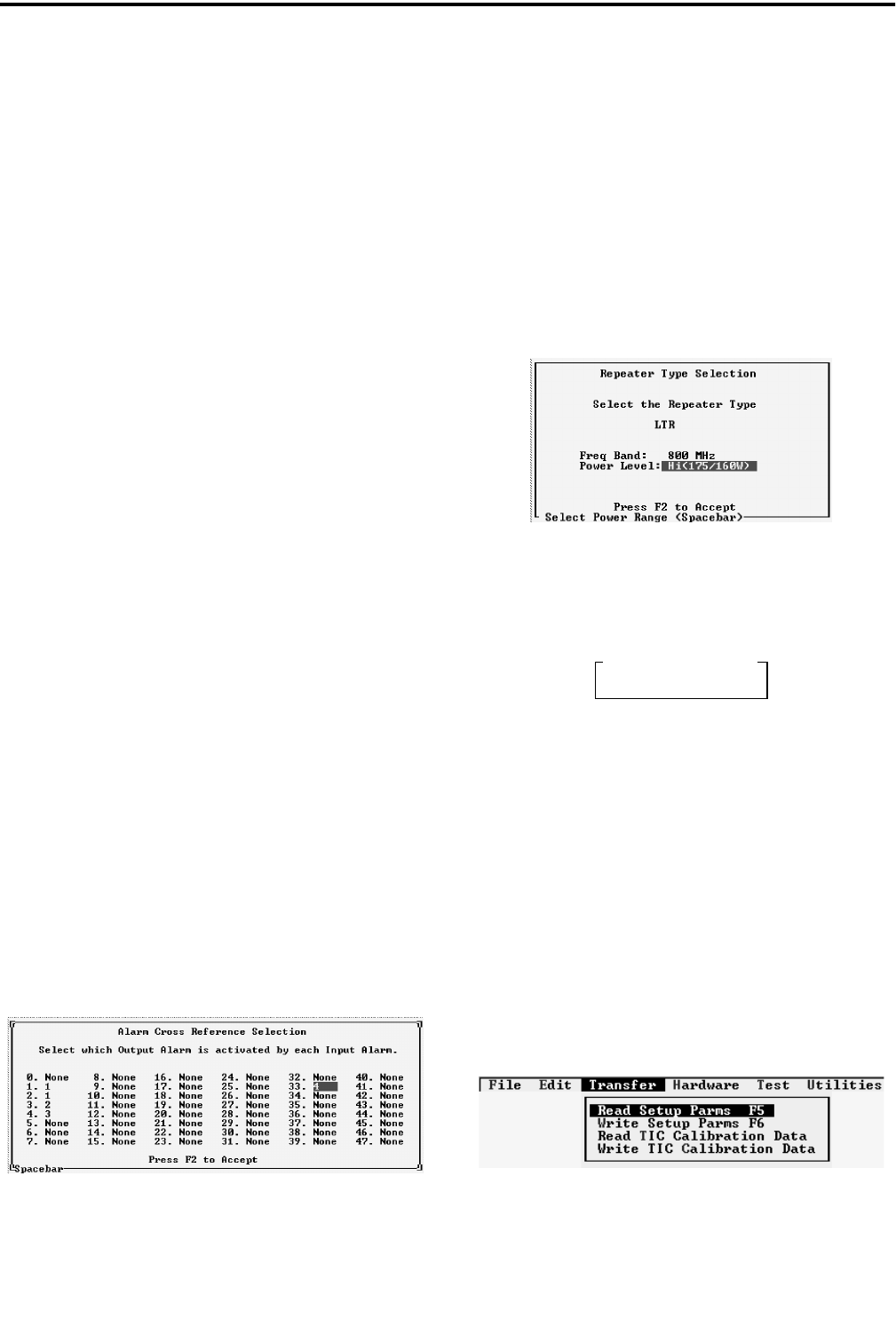
PULL DOWN MENUS
4-5 May 2000
Part No. 001-2008-204
•Alarm Description
This is a text string (up to 15 characters) to
describe the alarm. This test string is sent via Morse
code if the alarm input is programmed with a Tx ID
and an output is selected in the cross reference menu
(see Figure 4-10).
•Transmit ID
Each of the 8-alarm outputs can be assigned a
Group ID from 1-225. The default setting is 0 (zero)
for disabled. This Group ID and the Repeater number
identify an alarm that is active. This ID can be pro-
grammed into a transceiver so that when the alarm is
active, the alarm description is received in Morse
code.
•Alarm Transmit Rate
This sets the time interval for transmitting the
alarm message in Morse code. If more than one alarm
is active, this is the inter-alarm time.
•Cross Reference
The cross reference screen selects the output
alarm that is activated by each input alarm. There are
up to 48 alarms (0-47), 8 external input alarms and 40
internal alarms (see Table 1-2). There are eight output
alarms. An alarm condition on any input can cause an
output alarm. This screen configures which input
alarm activates an output alarm.
NOTE: More than one alarm condition can have the
same output alarm (see Figure 4-10).
Figure 4-10 ALARM CROSS REFERENCE
4.3.4 REPEATER TYPE
This screen (see Figure 4-11) selects the repeater
type (LTR signaling protocol and features):
Frequency Band 800 MHz
800 MHz [-12.5 kHz]
900 MHz
Power Level 75W
175W
Figure 4-11 REPEATER TYPE
4.3.5 DELETE REPEATER
Figure 4-12 DELETE REPEATER
4.3.6 TELEPHONE PARAMETERS
Refer to the Telephone Interface Card manual,
Part No. 004-2000-370, for information on the Tele-
phone Access Parameters, Telephone Interface and
TIC Calibration Data.
4.4 TRANSFER
Figure 4-13 TRANSFER MENU
Select Rptr To Delete
Rptr 1
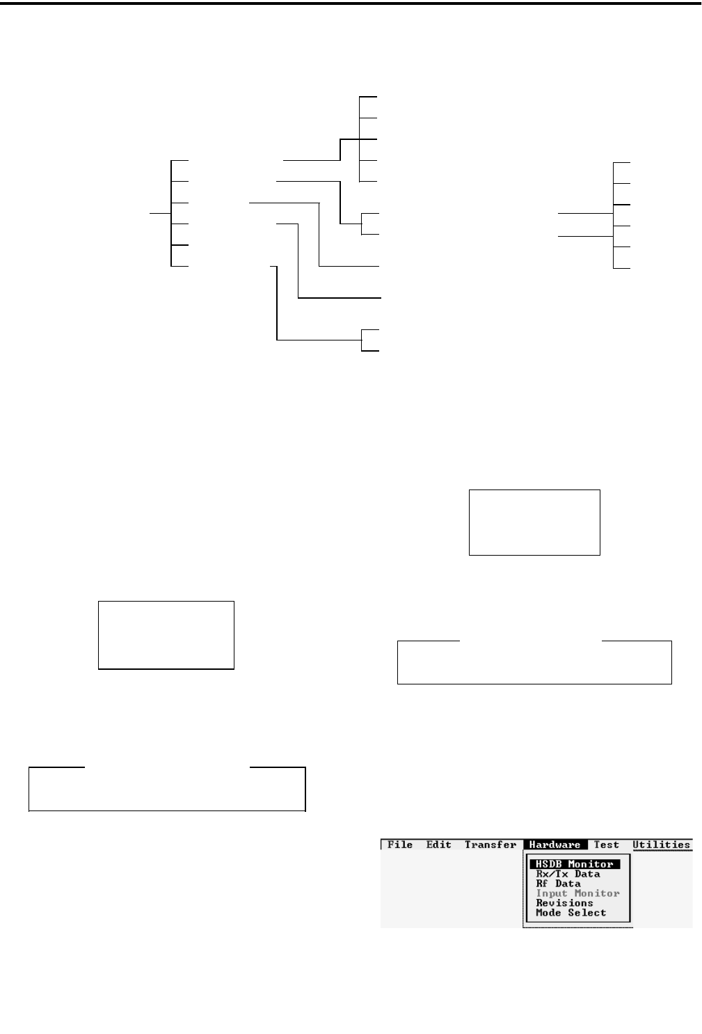
PULL DOWN MENUS
4-6
May 2000
Part No. 001-2008-204
4.4.1 WRITE SETUP PARAMETERS
This command sends the contents of a file to the
repeater and programs the EEPROM memory in the
Main Processor Card (MPC).
Figure 4-15 WRITE SETUP PARAMETERS
Figure 4-16 PROGRAM WRITE SETUP
4.4.2 READ SETUP PARAMETERS
This command reads the contents of the
EEPROM memory of a repeater and loads it into a
buffer. The contents of the buffer is then displayed to
show the programming of the repeater.
Figure 4-17 READ SETUP PARAMETERS
Figure 4-18 READING SETUP
4.5 HARDWARE
Figure 4-19 HARDWARE MENU
Program Rptr 1
Ok Cancel
Programming Setup Parameters
Count = 1
Ok Cancel
Read Setup Parms?
Reading Setup Parameters
Attempting access to Repeater
Figure 4-14 HARDWARE PROGRAMMING FLOWCHART
Home
UID
GoTo
GID
Data Received From Radio
Data Transmitted to Radio
Home
UID
GID
Pri
Stat
Time
HSDB Monitor
RX/TX Data
HARDWARE RF Data
RF Line MonitorMode Select
Normal
Test
Revisions
Input Monitor
Input Alarm 3/4 Analog Monitor
Repeater (1-20)
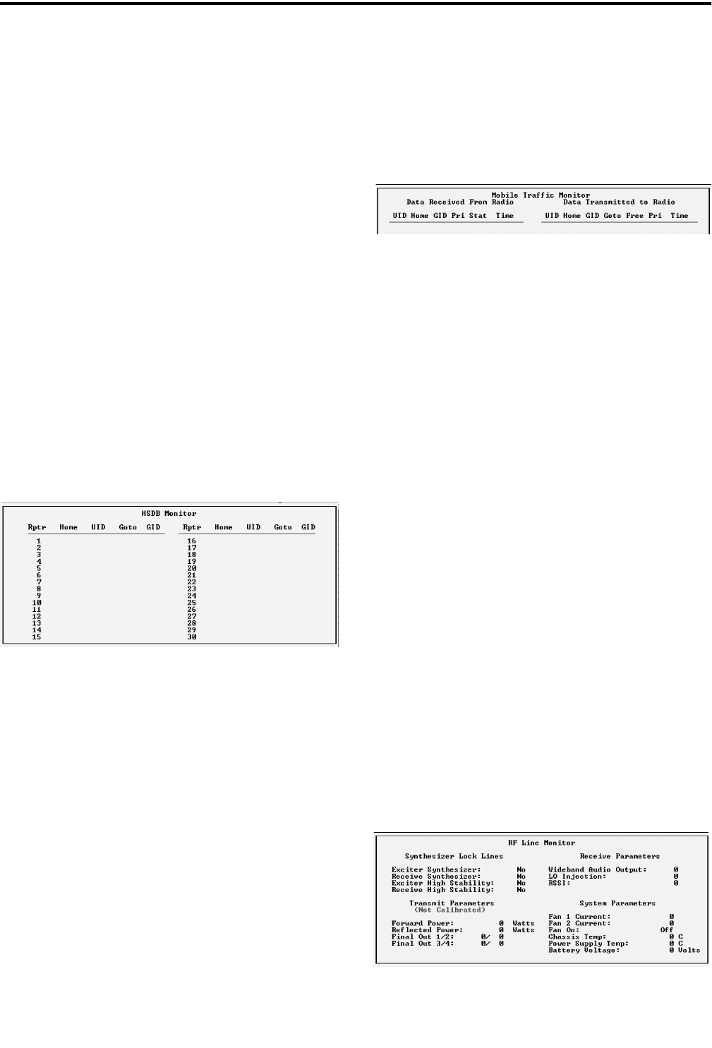
PULL DOWN MENUS
4-7 May 2000
Part No. 001-2008-204
4.5.1 HSDB MONITOR
High Speed Data Bus (HSDB) connects all
repeaters at a site and continually sends updates on the
status of each repeater. This information screen pro-
vides a list of all repeaters at the site (1 to 20). If a
repeater is not sending data, IDLE is next to the
repeater number. The data sent by the repeater is used
to determine the Home, GID and UID of destination
(mobile) users to receive the call placed by the origi-
nator.
The Home column refers to the Home repeater
number of the originator, therefore the Repeater num-
ber and the Home number may not be the same num-
ber. The UID is the Unique ID used to identify the
originator of special calls. The GID column refers to
the Group ID of the talk group of the originator
(236=UID Call, 237 Telco call). The GoTo column
shows the repeater channel all destination users switch
to so they receive the call.
Figure 4-20 HSDB MONITOR
4.5.2 RECEIVE/TRANSMIT DATA
This is an information screen used at the repeater
site while the computer (laptop) is connected to the
MPC in the repeater being monitored. This informa-
tion is contained in the receive data stream exchanged
between the repeater and the destination user (mobile)
and the data content of the repeater transmit data
stream. The message contains data received from the
destination and data sent to the mobile by the repeater.
The repeater receives the destination’s: Unique ID,
Home Repeater Number, Group ID, Priority, Status
and Time Stamp. The information sent to the destina-
tion in the update message from the repeater includes:
Unique ID of originator, Home Repeater Number,
Group ID, GoTo Channel Number, Free Channel
Number and Priority of the current repeater. The time
stamp is included because messages are sent continu-
ally and this provides a reference for when a data
exchange took place.
Figure 4-21 MOBILE TRAFFIC MONITOR
4.5.3 RF DATA
The A/D Monitor Screen shows the state of the
lines (see Figure 4-22). These lines are monitored by
the A to D converter in the IAC. The normal values
for each line are defined as follows.
Synthesizer Lock Lines Yes or No
Forward Power (LP) 25-75 Watts
Forward Power (HP) 75-175 Watts
Reflected Power 0-6 Watts
Final Out (ratio) approx equal
Chassis Temp 27°C-55°C
Wideband Audio Output approx 200
LO Injection approx 200
RSSI 20-150
Fan Current 100-200, 0
Fan On or Off
Power Supply Temp 22°C-45°C
Battery Voltage 21V-28V
Values with no label are the actual A to D read-
ing. To calculate the voltage on the line, divide the
value by 51. Example: Value ÷ 51 = Volts. Any varia-
tion from the above values may indicate a problem in
that area. Values on this screen are relative measure-
ments only.
Figure 4-22 RF LINE MONITOR
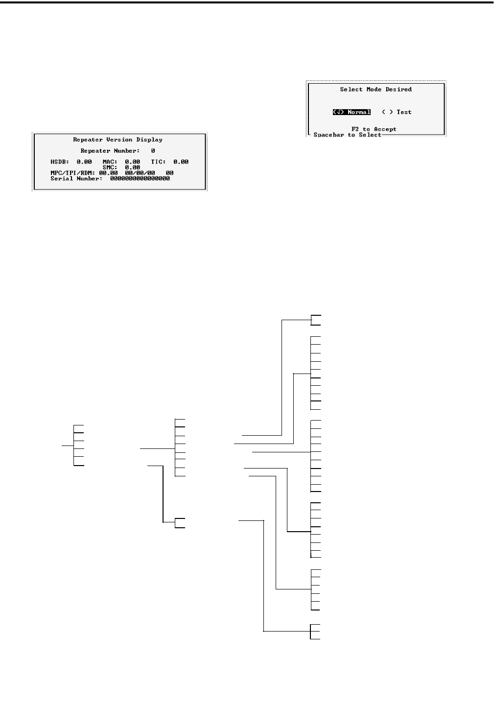
PULL DOWN MENUS
4-8
May 2000
Part No. 001-2008-204
4.5.4 REVISION/VERSION
The Revision/Version is displayed for the
repeater modules in this screen. The format is R.V
(revision.version) for all modules. The MPC informa-
tion also includes the release date of the software and
the serial number of the repeater.
Figure 4-23 REVISION/VERSION
4.5.5 MODE SELECT
The Mode Select screen places the repeater either
in the Normal mode or the Test mode. In the Normal
mode the repeater operates as a normal repeater.
In the Test mode the repeater transmits a test
word. This test word is the Test Mode ID setup in the
Setup Parameters (see Section 4.3.1).
C A U T I O N
While in the test mode the repeater is "busy",
therefore it is important to place the repeater
in Normal mode when the test mode is no
longer required.
Figure 4-24 TEST PROGRAMMING FLOWCHART
All Test
Frequency Adjust
PA
TEST
Select Line Type
Data Over Voice (2-Wire)
All Receive Tests
All Transmit Tests
All Audio/Data Tests
All Operational Tests
Separate Data (4-Wire)
RS-2332
New HSDB Test
Old HSDB Test
Handshake Test
Alarm Test
Spurious Check
Voice Audio From Repeater
Voice Audio To Repeater
FSK Data To Rptr (Separate Path)
FSK Data To Rptr (Over Voice Path)
FSK Data From RNT (Separate Path)
FSK Data From Rptr (Over Voice Path)
RS-232 Setup
Audio Deviation Limit
Repeat Audio Level
Data Level Adjust
Audio/Data Deviation
CWID Level Check
Local Speaker/Mic
Tx Hum & Noise Ratio
Transmit Audio Distortion
LTR Modem
Power Output Adjust
TCXO Frequency Adjust
Audio Distortion
Hum & Noise Measurement
SINAD Measurement
Squelch Adjust
Data Level Adjust
Local Speaker/Mic
Desense Check
Miscellaneous Tests
Repeater Setup
Transmitter Tests
Receiver Tests
Transmit Audio/Data
Voter Audio Adjust
Audio/Data Adjust
Repeater Operation
Adjust Links
Receiver
Exciter
Full Rptr/Station
RNT Interface
Telephone Interface
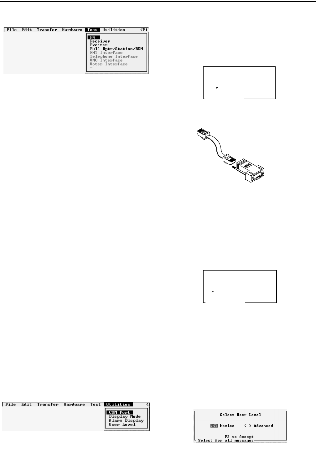
PULL DOWN MENUS
4-9 May 2000
Part No. 001-2008-204
4.6 TEST
Figure 4-25 TEST MENU
4.6.1 POWER AMPLIFIER
This menu selection walks through the alignment
of the Power Amplifier and RF Interface Board on the
computer screen. Refer to Sections 7.3 and 7.4 for the
PA and RFIB alignment in this manual and Figures 7-
3, 7-6, 7-4 and 7-7 for an alignment points diagram
and Figures 7-10 and 7-11 of the Power Amplifier.
4.6.2 RECEIVER
This menu selection walks through the alignment
of the receiver on the computer screen. Refer to Sec-
tion 7.1 for the Receiver alignment in this manual and
Figure 7-1 for an alignment points diagram and
Figure 7-8 of the Receiver.
4.6.3 EXCITER
This menu selection walks through the alignment
of the Exciter on the computer screen. Refer to Sec-
tion 7.2 for the Exciter alignment and Figure 7-2 for
an alignment points diagram and Figure 7-9 for a test
setup of the Exciter.
4.6.4 FULL REPEATER
This menu selection walks through the alignment
of the entire repeater. The Receiver and Exciter por-
tions are performance tests and adjustments. The
Audio and Data portions are level adjustments for the
Main Audio Card (MAC). Refer to Figure 7-18 for an
alignment points diagram for the MAC.
4.7 UTILITIES
4.7.1 COM PORT
This is the COM port used to send and receive
data from the Repeater MPC. An interface cable con-
nects the Repeater to the computer (see Figure 4-26).
This screen also selects the data baud rate.
Figure 4-26 LAPTOP CABLE
4.7.2 DISPLAY MODE
This screen allows the color mode to be selected
for color monitors. When using a laptop, monochrome
is recommended for better resolution.
4.7.3 USER LEVEL
There are two levels to choose from, Novice and
Advanced. The Novice uses prompts in the Edit-
Parameters screens when Escape or F2 keys are
pressed that ask "are you sure" before the task is exe-
cuted. The Advanced selection performs the task
without asking the question.
Select COM Port Desired
Spacebar to Select
( ) COM 1 ( ) COM 2
Baud rate: 9600
TO MPC
TO LAPTOP
Spacebar to Select
Select Color Mode Desired
( ) Color ( ) Monochrome

PULL DOWN MENUS
4-10
May 2000
Part No. 001-2008-204

5-1 May 2000
Part No. 001-2008-204
REPEATER PROGRAMMING
SECTION 5 REPEATER PROGRAMMING
5.1 CREATING A NEW FILE
An example will be used to show the program-
ming for a new file created for Site 1.
NOTE: At any point in the programming sequence, if
F1 is selected, a help screen appears to explain the
menu selection highlighted at that point.
5.1.1 SELECT REPEATER TO EDIT
A repeater is selected to program. When no file
exists with programmed repeaters, the default is
selected and edited.
1. Highlight EDIT, press Enter.
2. Highlight SELECT REPEATER, press Enter.
3. Default is the only repeater in this list, press Enter.
4. Highlight EDIT, press Enter.
5. Highlight SETUP PARAMETERS, press Enter.
6. The Setup Parameters screen appears (see Figure 5-
1). Fill in the parameters for this repeater. A brief
description of the parameters is in Table 5-1. Full
descriptions are in Section 4.3.1.
7. Select parameters, press F2 to accept.
8. Highlight EDIT, press Enter.
9. Highlight ALARM CONFIGURATION and press
Enter, if alarms are to be configured.
10.Program the Alarms to be configured (see Section
4.3.3), press F2 to accept.
11.Highlight FILES, press Enter.
12.Highlight SAVE, press Enter.
13.Type in a valid DOS filename. For this example
site1.dat is used.
14.The file consists of default and repeater one under
the filename of site1.dat.
5.2 ADDING A REPEATER TO A FILE
The example used for Site 1 will again be used to
add repeaters to the filename site1.dat.
1. Highlight EDIT, press Enter.
2. Highlight SELECT REPEATER, press Enter.
3. The repeater list shown for this file includes default
and repeater one. These contain the same parame-
ters with the exception that when selected for edit
the programmed repeater can be overwritten and the
data lost.
4. Highlight DEFAULT, press Enter.
5. Highlight EDIT, press Enter.
6. Highlight SETUP PARAMETERS, press Enter.
7. Change the Repeater number and other parameters
as required for this repeater, press F2.
8. Highlight EDIT, press Enter.
9. Highlight ALARM CONFIGURATION and press
Enter, if alarms are to be configured.
10.Program the Alarms to be configured (see Section
4.3.3), press F2 to accept.
11.Highlight FILES, press Enter.
12.Highlight SAVE, press Enter.
13.Repeater 2 is added to the Repeater List in file
site1.dat.
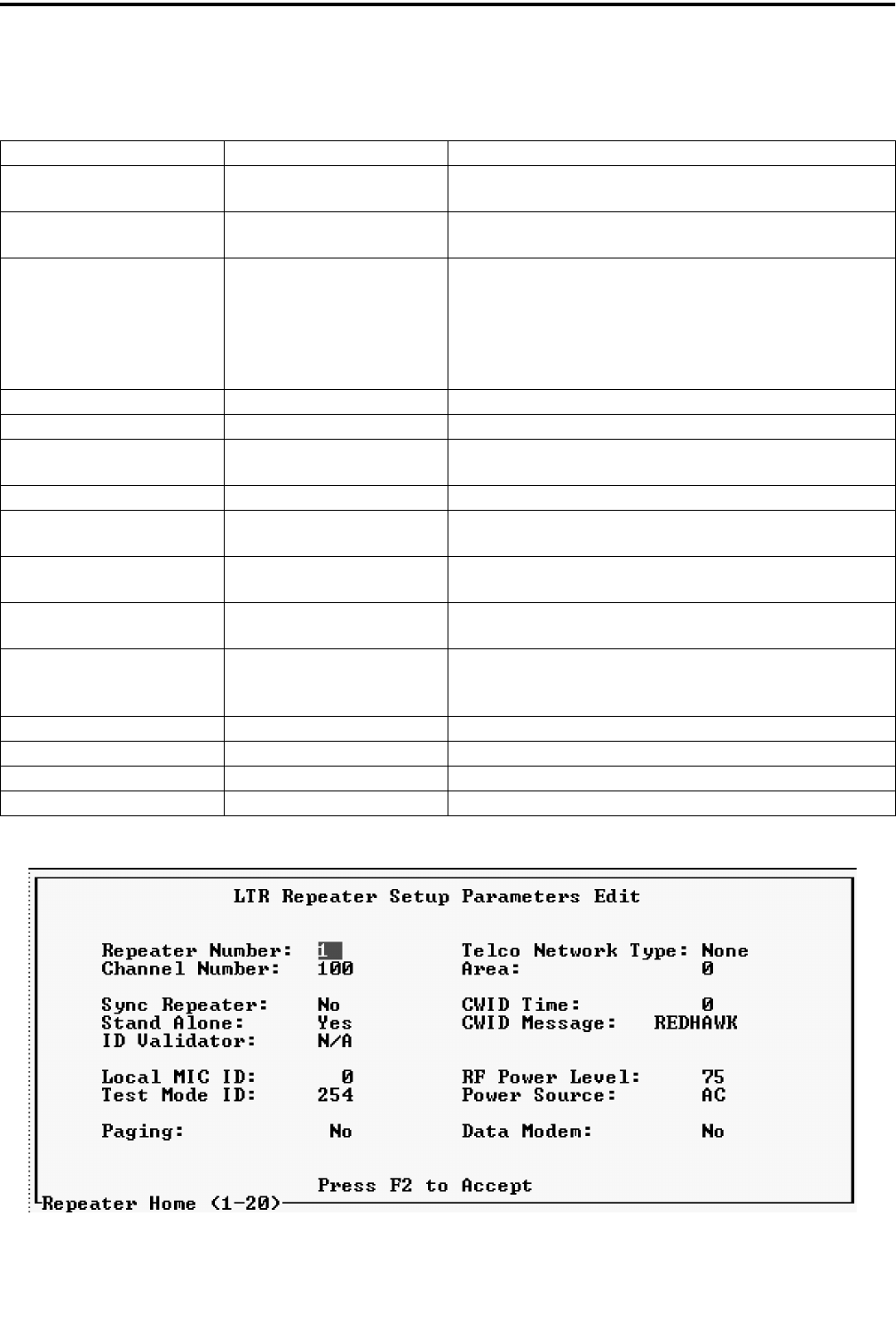
REPEATER PROGRAMMING
5-2
May 2000
Part No. 001-2008-204
Figure 5-1 SETUP PARAMETERS
Table 5-1 REPEATER SETUP PARAMETERS
Parameter Response Description
Repeater Number 1-20 Each repeater is assigned a Home Repeater number from 1-
20.
Channel Number 1-920 Each repeater is programmed with a number of the channel
that it is operating on.
Telco Network Type None
FSK
RS232
FSK Blank & Burst
TIC
VNC
Data signaling type for RNT, FSK, RS232 or FSK B&B.
None=LTR dispatch only.
TIC is for Telephone Interface Card w/o RNT.
VNC=network telephone interconnect w/o RNT.
Area 0, 1 Same as value of the Area bit in the mobiles.
Sync Repeater No Not used.
Stand Alone Yes, No Select if the repeater is not connected to additional repeaters
(via HSDB).
ID Validator Yes, No Not used.
CWID Time 0 = disabled
1-60 min Time between CWID transmissions.
CWID Message 15 characters/numbers
UPPER CASE Station call letters.
Local MIC ID 0 = transmits carrier
1-250, 253 Group ID transmitted when the local microphone PTT is
active.
Test Mode ID 0 =transmits carrier
1-250,
254 (default)
Group ID transmitted when the Repeater is in the Test Mode.
RF Power Level 25-75, 75-175 Power level in watts for transmit power.
Power Source AC or DC The type of primary power source for the Repeater.
Paging Yes, No Select if a paging terminal is installed.
Data Modem Yes, No Select if the Data Modem option is installed.