ECI Satellite Communication A S RTU4120A Iridium Telephone System User Manual Installation manual Sailor
ECI Satellite Communication A/S Iridium Telephone System Installation manual Sailor
Contents
- 1. User manual Sailor
- 2. User manual Skanti
- 3. User manual Iridium
- 4. Installation manual Sailor
- 5. Installation manual Skanti
Installation manual Sailor

SAILOR SC4150
Installation Manual
Single-channel Unit

Introduction
Congratulations on your new Iridium handset or PSTN (Public
Switched Telephone Network) telephone.
Your Iridium system is a modular system that consists of an antenna,
transmitter/receiver, handset and optional PSTN telephone/PBX
(Private Branch Exchange) switchboard.
You can operate the Iridium system in voice mode from a handset
and/or PSTN telephone. To the system you can connect up to five
handsets and one PSTN telephone or PBX switchboard.
Sailor marine equipment is specially designed for the extremely
rugged conditions on board a ship, based on more than 50 years of
experience with all kinds of boats, from small pleasure crafts, over
fishing boats working under all climatic conditions, to the biggest
ships.
EuroCom Industries A/S (ECI) develops and produces high-
technology maritime communications equipment under the
brandname Sailor .
ECI is one of the world’s largest suppliers of communications
equipment for the maritime segment, a position which has been
maintained by means of constant and extensive product develop-
ment.
The Sailor products are sold through a global network with more
than 60 qualified and trained distributors.
Please note
Any responsibility or liability for loss or damage in connection with
the use of this product and the accompanying documentation is
disclaimed. The information in this manual is furnished for informa-
tional use only, is subject to change without notice, may contain
errors or inaccuracies, and represents no commitment whatsoever.
This agreement is governed by the laws of Denmark.
Doc. no.: M4150GB0 Issue: G/0303

1
Installation
IRIDIUM
0225
Contents
1 Configuration of Single-Channel Unit.............................................................................................................. 2
2 Installation .......................................................................................................................................................... 3
2.1 Cable Overview .................................................................................................................................................... 3
2.1.1 Scanbus Termination ............................................................................................................................................ 5
2.2 Where to Place the Satellite Transceiver Box ..................................................................................................... 7
2.3 How to Mount the Satellite Transceiver Box ........................................................................................................ 8
2.4 How to Put on the Finishing Cover ...................................................................................................................... 9
2.5 How to Insert the SIM Card.................................................................................................................................. 10
2.6 How to Remove the Finishing Cover ................................................................................................................... 11
2.7 Installation of the Antenna.................................................................................................................................... 12
2.8 PABX/PSTN Interface .......................................................................................................................................... 15
2.9 Data Interface ....................................................................................................................................................... 15
Appendix A ..................................................................................................................................................................... 17
Spareparts List ..................................................................................................................................................... 17
2
Installation IRIDIUM
0225
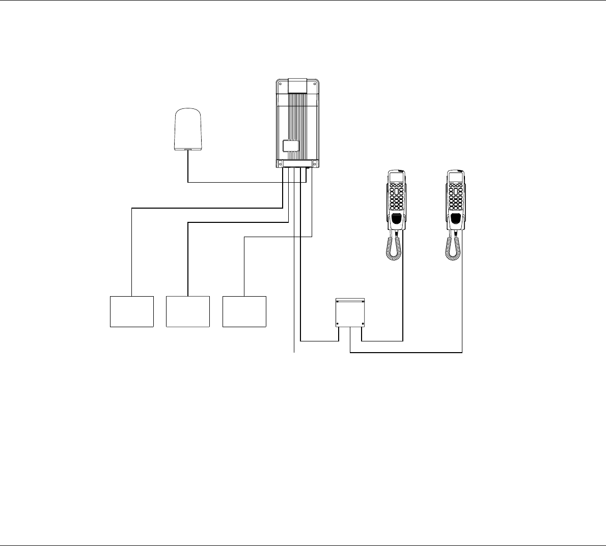
1 Configuration of Single-Channel Unit
L1
35423E
10 - 32V DC
PABX
Phone
DTE
2
3
4
1
Antenna Unit
Max. cable loss 3dB
Iridium
L1 + L2 < 100 metres
L2
Box
Connection
5
1
Handset
Control
Handset
Transceiver
Unit
Control
6
GPS
3
Installation
IRIDIUM
2 Installation
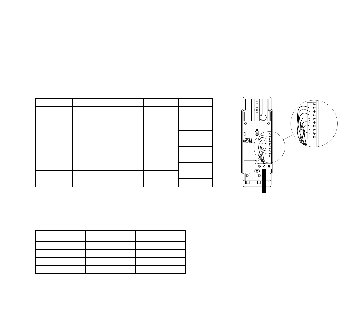
2.1 Cable Overview
Cable 1
Scanbus
Cable: 9*0.22 mm2shielded
shield connected to ground
Cable connector type: 9 pole sub-d male
Transceiver Description Handset Colour
1NC1
2 data+ 2 white Twisted
3 data- 3 brown pairs
4AF+4greenTwisted
5 AF- 5 yellow pairs
6 GND 6 grey Twisted
7 +24V DC 7 pink pairs
8RX_AF+8 blue Twisted
9 RX_AF- 9 red pairs
shield GND shield
2
3
4
5
6
7
8
9
1
10
36088
Cable 2
Phone
Cable connector type: RJ 11
Transceiver Description Veritas
1NC1
2 phone1+ 2
3 phone1- 3
4NC4
Cable 3
Data
Cable: 9*0.22 mm2shielded
shield connected to ground
Cable connector type: 9 pole sub-d male
0225
4
Installation IRIDIUM
0225
Transceiver Description Veritas
1 DCD 1
2 received data 2
3 transmitted data 3
4 data terminal ready 4
5serial GND5
6 data set ready 6
7 request to send 7
8 clear to send 8
9RI9
shield GND shield
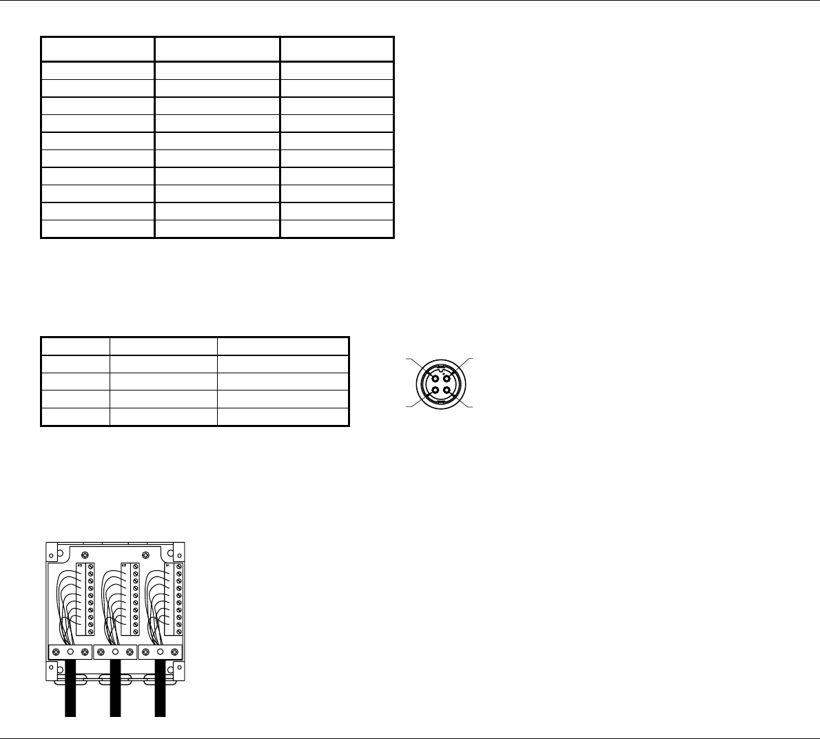
Cable 4
Power supply Front view
Pin no. Description Colour
1 10-32V DC red
20V DC black
3NC white
4GND green
4
3
1
2
36662A
Cable 5
Description of connections to T-connection H4196
The wire terminal blocks are connected in parallel.
36090
5
Installation
IRIDIUM
Cable 6
GPS input
Cable: 9*0.22 mm2shielded
shield connected to ground
Cable connector type: 9 pole sub-d male
Transceiver Description Veritas
1 NC* 1
2 PC Rx (RS232) 2
3PC Tx (RS232)3
4 NC* 4
5 GND (RS232) 5
6 NC* 6
7 NMEA+ 7
8 NMEA- 8
9 NC* 9
shield GND shield
* Do only connect a standard RS232 terminal cable. If only NMEA needed, then do not connect to other pins than 7
and 8.
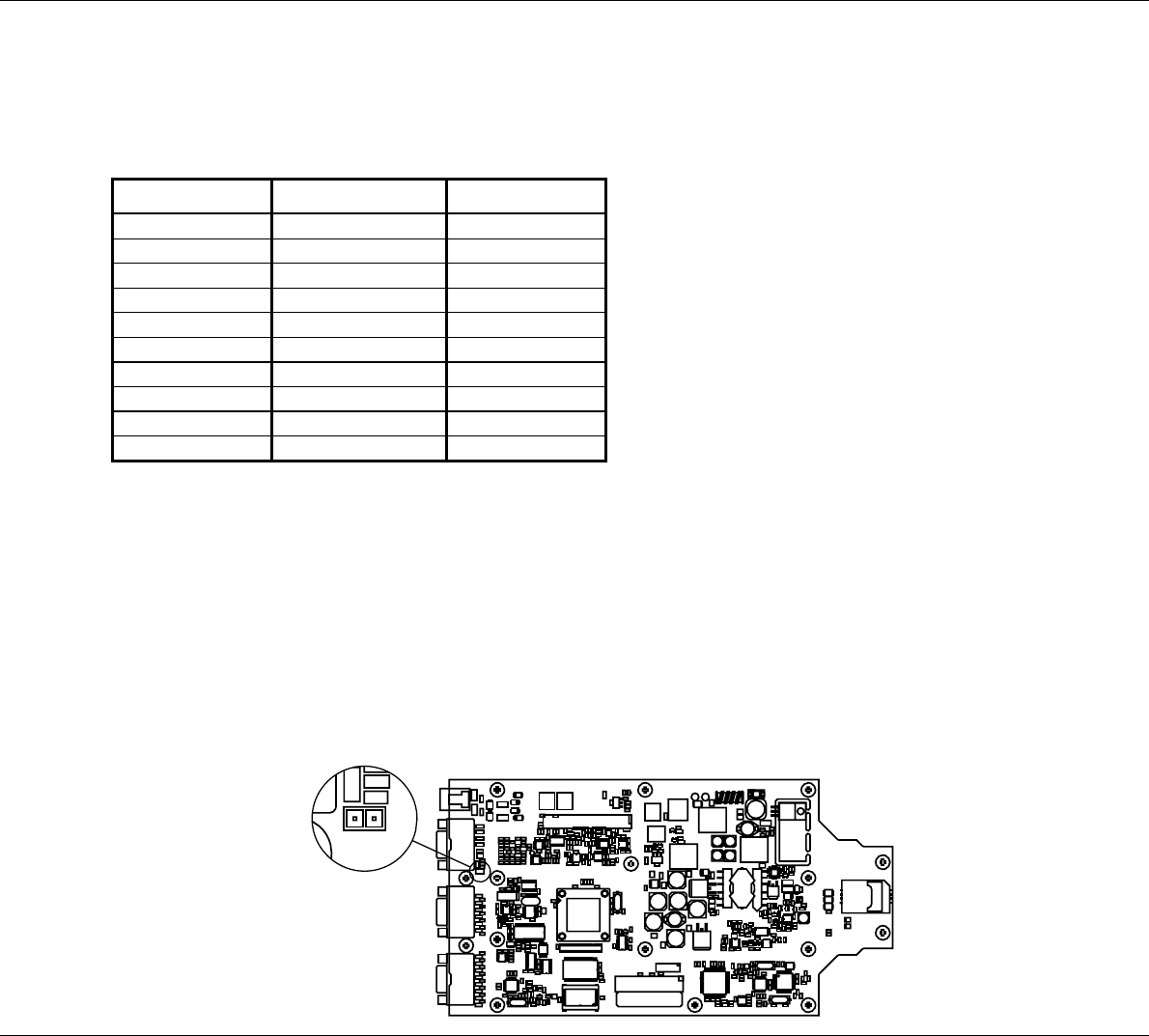
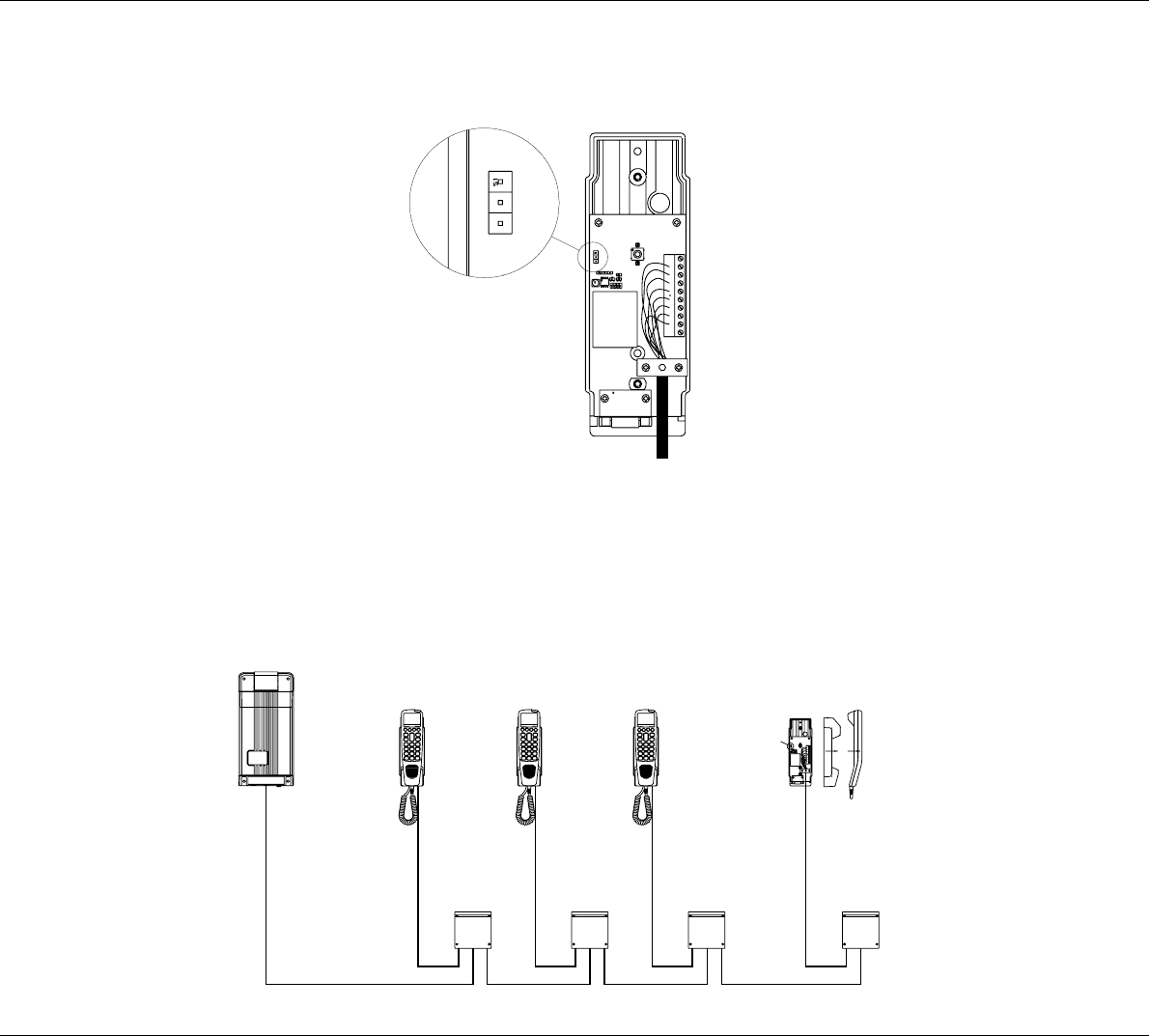
2.1.1 Scanbus Termination
The scanbus connectiong the transceiver and the control units, has to be terminated. Only the first and last unit on the
bus shall have the termination in ON position.
The termination in the transceiver unit is done by setting the jumper S3, located near the scanbus terminal on the PCB
(see figure below). As default, the jumper S3 is set ON.
38638
C65
C138
C131
C194
C1
C142
C9
C24
R187
C5
R85
C154
D6
R159
R12
C196
R11
X2
R180
D12
C102
D5
C20
R217
R15
R223
D9
R216
D4
X10
C132
Z4
V10
Z2
C202
R95
C163
C215
C10
C87
C4
X4
V3
R49
R48
L2
R26 R30
D14
R63
C22
R31
R27
R28
R55
V17
R51
V8
C56
C184
C203
C38
R53
R46
V4
V18
R57
R60
V20
R146
R5
R76
R111
R102
C15
R82 R68
C30
R56
D16
R29
R45
V7
X5
Z31
D2
C92
C89
Z28
C88
Z34
Z32
C91
Z33
Z15
C83
Z29
C84
C90
Z30
C85
Z39
C97
C81
C164
R33
R44
C79
R25
C19
C43
C37
D13
C34
C60
V15
C23
C95
Z36
C76
C94
Z38
Z37
Z40
C96
N3
D8
C59
C135
C2
V13
R24
C39
R32
R47
C130
V28
C52
C40
C133
D10
C134
R109
R110
C139
C51
R42
C82
R122
R50
C101
C14
R10
C17
R197
V49
V45
R34
R22
N1
C3
R101
C218
C98
C213 C162
R135
C200
C157
R96
R124
R183
R108
C74
R88
C72
R4
R118
R100
R121
C114
R98
C27
R99
C35
C199
C61
R123
C113
C62
C172
C120
C57
N4
V66
V62
C28
N9
C36
C209
C210
V61
R35
R199
V68
R200
R214
R97
V60
R198
V57
C171
C99
C41
C109
R43
R83
N5
C68
N8
R6
C147
R38
N13
C86
C106
R39
R220
R119
R40
R151
C103
R13
R152
R185
C177
C217
C110
C152
C208
R154
R107
C12
X3
C13
C156
Z10
C169
Z8
R1
C67
C107
C111
R120
C207
R125
R84
C158
C175
R168
R106
R66
R128
R58
R54
V14
V19
R52
Z9
C192
Z12
Z11
S3
R162
C77
C78
X8
Z13
C124
C32
R2
C26 C25
V26
V11
V27
V31
V33
V12
R77
R78
N15
C204
R104
C125
C49 R92
C181
R112
C186 C188
C161
R114
R91
R87
R115
C182
C190
R150
C191
R94
C173
C174
R86
C205
C48
R113
C189
C148
C53
R90
C187
R116
R117
N12
N2
C176
C178
R89
C55
R149
C167
R93
C6
C170
C11
R224
R169
C31
C150
R225
R166
R103
C225
R3
C115
C193
R167
C155
N14
R59
V16
C220
C136
Z3
C93
Z35
Z6
C137
C16
C219
C105
R105
C108
R189
R190
C47
V73
V58
R132
R175
V59
R16
R193
R208
C216
C128
C117
R165
R7
R170 R172
R215
C21
V36
N10
N11
R21
R142
R19
R141
V30
R174
R18
R206
R164
R145
C75
V69
C143
Z14
R209
R69
C7
R184
V65
R156
R171
V37
R158
V40
R71
V21
D11
C50
C141
R17
X1
C18
R157
R62
R67
R74
V35
R73
R64
C45
C44
C42
C66
C46
Z5
C198
R70
C80
R61
R9
R23
C166
V23
L3
C58
R72
V24
C201
C180
R41
C214
R126
R127
R163
C8
R20
C195
D15
D3
V53
L7
V46
C33
V52
C116
N6
C69
V44
R80
R81
C63
R144
N7
R210
R177
C211
C206
V47
R203
R178
C112
C104
R182
R179
R147
R138
R204
R140
R36
R133
C185
V43
R137
V32
V41
C126
R194
R143
R207
C100
V67
C159
R211
R148
V29
C54
R8
V25
C71
C70
C165
C183
R75
R65
R14
R161
V22
X6
V72
V70
V38
R130
R79
C119
C118
C197
C149
C151
V64
C168
C146
V54
V51
V50
R131
R139
R188
R213
C127
V63
R191
C140
V39
C153
R192
R212
C73
C129
V74 V34
C29
R134
V48
C121
C122
C123
C64
R195
C212
R129
V42
R37
R136
F1
L5
C160
V55
C144
L4
C179
X9 X7
C145
V56
R196
S3
R162
C78
Z13
0225
6
Installation IRIDIUM
The termination in the control unit is located on the PCB in the cradle as jumper S1 (see figure below). As default the
jumper S1 is set ON.
38637
S1
ON
OFF
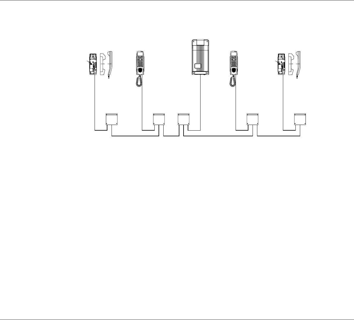
When configuring a system only including a transceiver unit and one control unit, no changes in the default termination
is needed. If the system includes more than one control unit, it is needed to remove some of the default terminations.
Below two examples of scanbus termination is given, when the system includes several control units.
38635
Box
Connection
Transceiver Unit
Control Unit
Terminated
Terminated
0225
7
Installation
IRIDIUM
0225
Terminated Terminated
Connection
Box
Control Unit
Transceiver Unit
38636
2.2 Where to Place the Satellite Transceiver Box
Mount the satellite transceiver box in a place where it is sheltered from the wind, protected from the salty and humid
sea atmosphere. The temperature must not exceed 55° C.
To ensure that the SIM card is easily accessible, do not place the satellite transceiver box higher than 1.5 m above
the floor.
8
Installation IRIDIUM
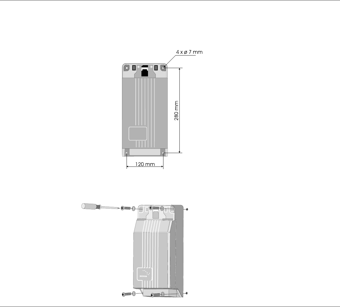
2.3 How to Mount the Satellite Transceiver Box
Fix the satellite transceiver box to the wall using the four screws included in the package. The screws are positioned
as shown below:
First tighten three of the screws. The wall surface should be plane. If there is a discrepancy in planeness exceeding
1 mm, level the discrepancy up by shims or washers under the fourth screw before this is tightened.
0225
9
Installation
IRIDIUM
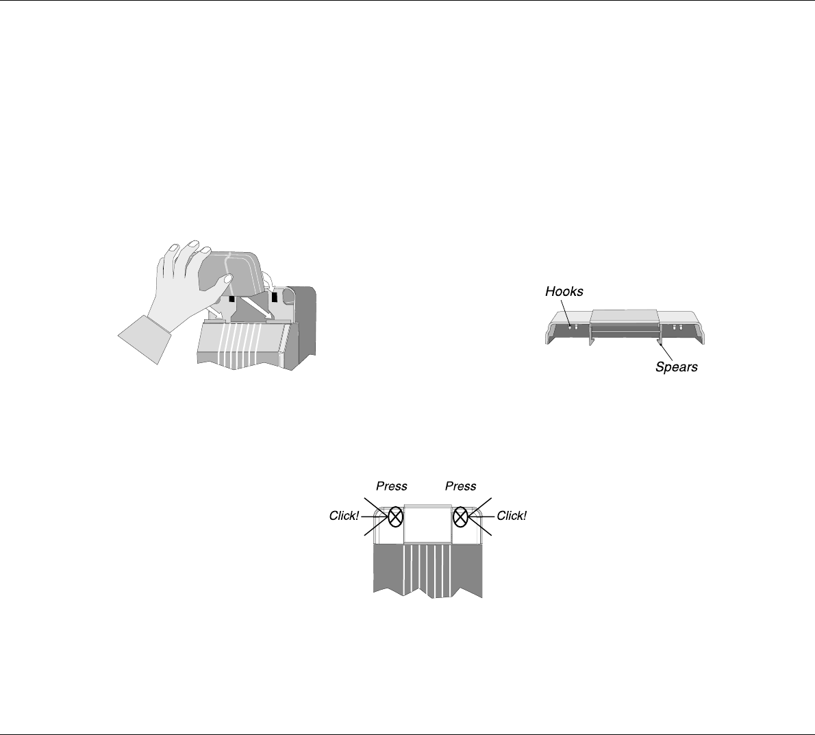
2.4 How to Put on the Finishing Cover
When the satellite transceiver box has been mounted on the wall, put on the finishing cover.
The small lid in the finishing cover should be shut. Press the hooks inside the finishing cover down on the two thin edges
of the satellite transceiver box. While pressing, let the two plastic spears inside the finishing cover into the two square
holes of the satellite transceiver box.
0225
Press hard on the spots shown in the picture below until a loud click is heard.
When putting on the finishing cover, do not use any tools – only your hands.
10
Installation IRIDIUM
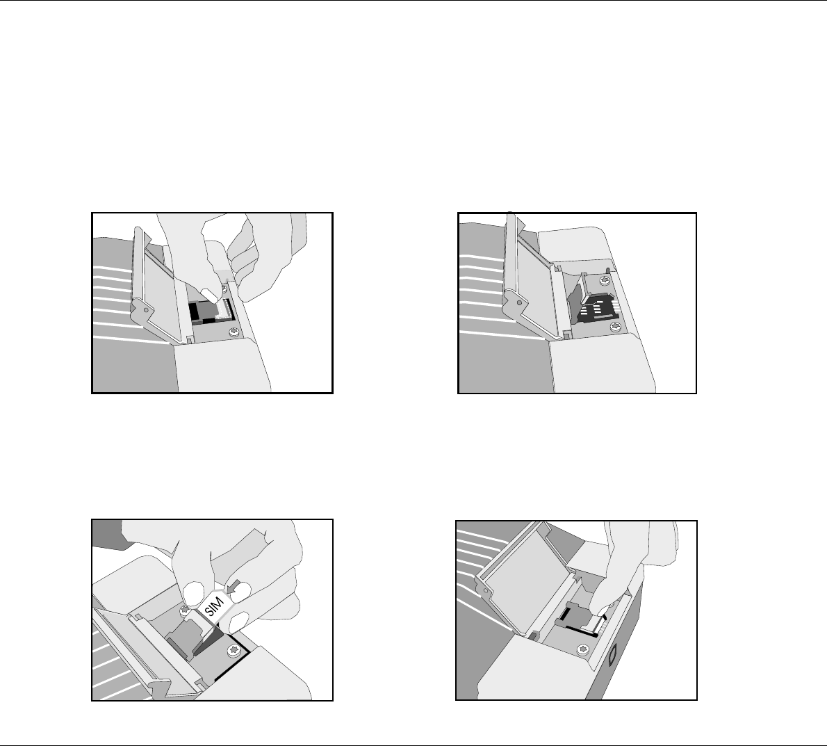
2.5 How to Insert the SIM Card
First, open the small lid in the finishing cover protecting
the SIM card reader. Then go through each of the follow-
ing steps:
Unlock the SIM card holder by pushing the lock with your
finger nail.
Lift the SIM card holder so that the slot points upwards.
0225
Insert the SIM card in the slot. Make sure that the cut-off
corner of the card is placed as shown in the picture.
Push the SIM card holder back down, and lock it by
pushing the lock with a finger nail.
Finally, shut the lid again.
11
Installation
IRIDIUM
0225
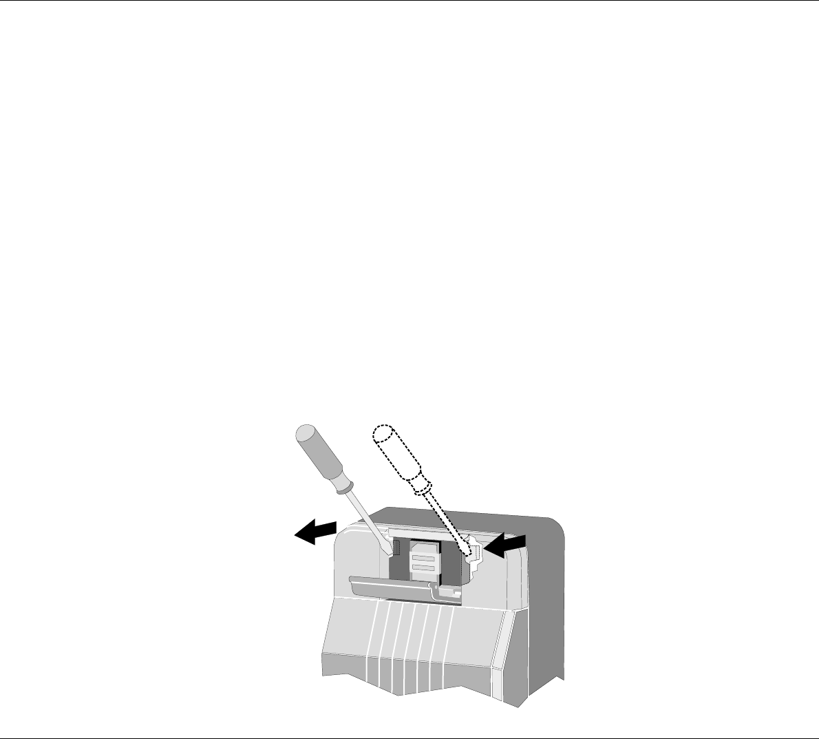
2.6 How to Remove the Finishing Cover
You may need to dismount the satellite transceiver box from the wall, e.g. in connection with service.
For access to the mounting screws, the finishing cover can be removed from the satellite transceiver box as follows:
Put a screwdriver into the slot in the printed circuit board beside the SIM card reader, and press gently
to unhook the plastic spear.
While pressing with the screwdriver, lift up the same side of the finishing cover slightly to loosen it.
Repeat this procedure on the other side of the finishing cover.
You can now detach the finishing cover from the satellite transceiver box by pulling it gently upwards.
12
Installation IRIDIUM
0303
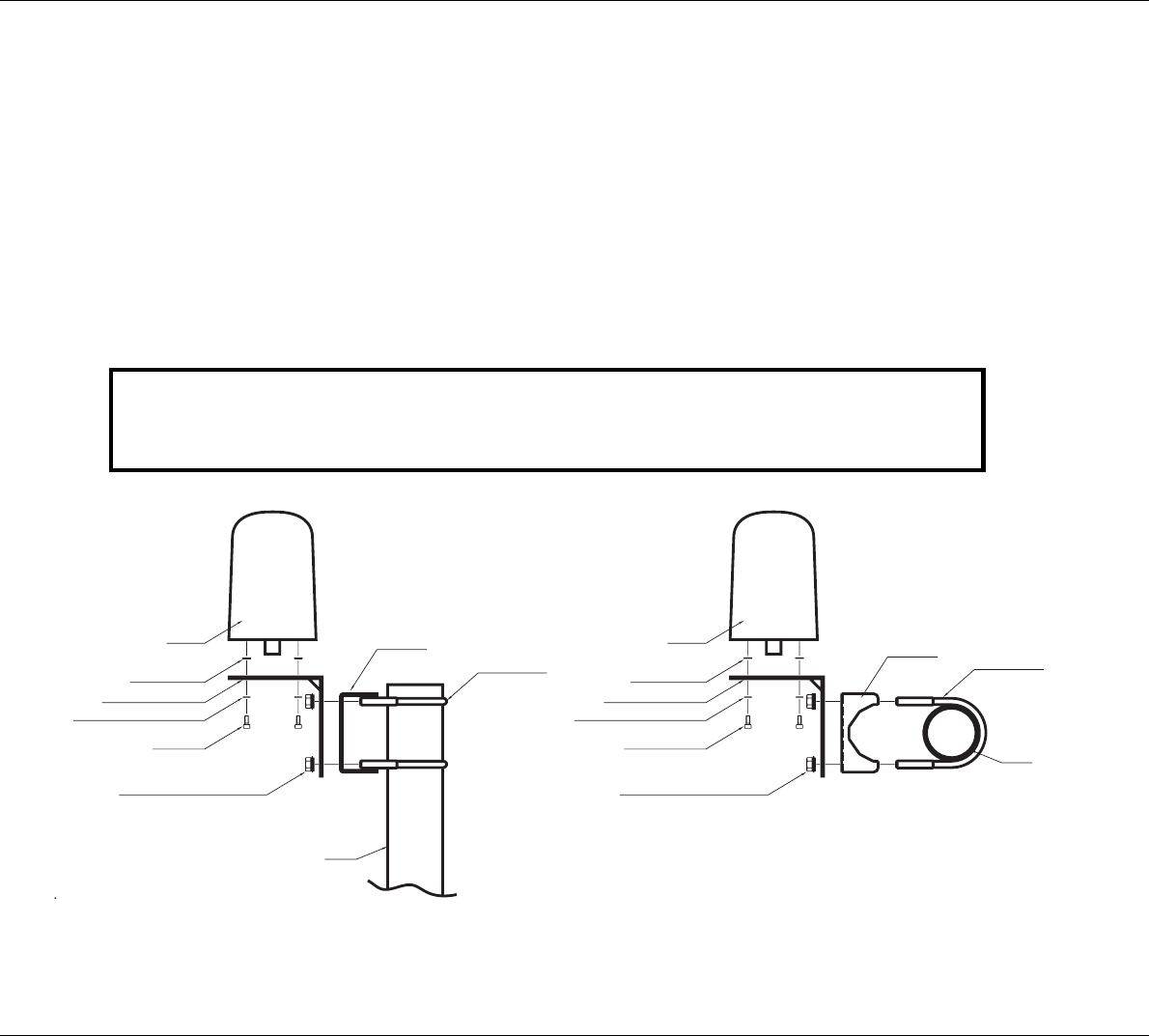
2.7 Installation of the Antenna
One of the advantages of this equipment is the easy-to-handle, lightweight and rugged antenna. Because the
IRIDIUM ® system is characterised by a good link margin, the antenna is a passive quadrifillar helix type, requiring
no external power supply and consisting of only nonmoving parts.
The following figures show the antenna and the two different mounting accessories available:
The mounting bracket in fig. 1 can be used in two different ways - mounted on either a rail or a pole.
The fitting in fig. 2 can be used at the top of a tube. Please note that it is necessary to mount the cable, and seal this
connection securely before the antenna and fitting are mounted on the tube.
2" pipe
Four M4x10
Four M4 serrated lock washers
Angle mounting bracket
Four M4 washers
Antenna
Four M8 lock nuts and M8 washers
Pipe clamp
Two M8 U-bolts
Four M4 serrated lock washers
Four M8 lock nuts and M8 washers
Four pieces M4x10
Angle mounting bracket
Four M4 washers
2" pipe
Two M8 U-bolts
Antenna
Pipe clamp
36623A
Fig. 1 Fig. 2
Important!
For FCC RF exposure compliance, the antenna must be installed with a minimum distance
of 0.61m (2 feet) away from all persons.
13
Installation
IRIDIUM
0225
Precautions
In order to avoid interference or any other kind of disturbances from other systems on board, there are a few
precautions to take note of:
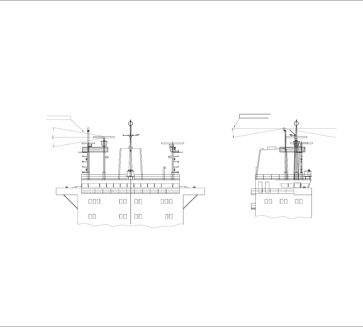
Radars
According to any installation guide for radars it is of vital importance that any other units are kept outside the
radiation beam of the radar. Please consult fig. 3, showing what area to avoid:
36622A
10°
e.g. from the radar
Avoid interference
10°10°
Unobstructed view until
10° below the horizon
GPS
Tests have shown that only in case very old GPS equipment is used, a user may expect a minor influence on
the GPS originated from the Iridium equipment. This can be avoided by ensuring a distance of at least 1 m
between the two antennas.
14
Installation IRIDIUM
Inmarsat equipment
The operating frequency bands of the iridium and Inmarsat systems are neighbours, and it is not in any way by
any technical solution possible to completely separate these bands. This means that interference from Inmarsat
can be expected, especially if the antennas are placed near each other. The distance between the antennas
Should be as far as possible.
If in any way the user experiences trouble using Iridium because of Inmarsat, a filter can be provided as an
option. This filter is placed in a suitable place between the antenna and the transceiver. The filter is a passive
type not requiring external power but the filter loss of 1.2 dB have to be added to the total cable loss between
the transceiver and the antenna. Please contact your dealer for further information.
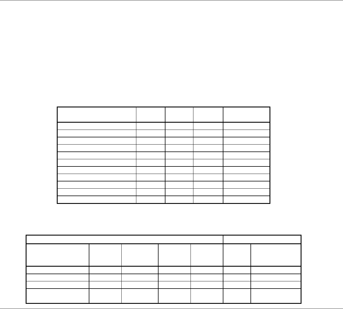
The table below shows the distance to other Inmarsat equipment, with and without use of filter.
9505 ISU Protection Distance Main Lobe
(Metres)
Side Lobe
(Metres)
Back-Lobe
(Metres)
No Filter 14 4 4 Inmarsat (Mini-M)
No Filter 25 4 4 Inmarsat (Std-M)
No Filter 84 20 20 Inmarsat A
No Filter 70 16 16 Inmarsat B
No Filter 14 14 14 Inmarsat C
With Filter 1 1 1 Inmarsat (Mini-M)
With Filter 1 1 1 Inmarsat (Std-M)
With Filter 4 1 1 Inmarsat A
With Filter 4 1 1 Inmarsat B
With Filter 1 1 1 Inmarsat C
Antenne cable
Below, please find a table of cables that can be provided by your dealer:
CABLE CONNECTOR
Cable type Part no.
Maximum
length/ 3 dB
loss
Outer
diameter
Minimum
bending
radius
Conn.
type Part no.
RG 214/U E62.415 8 m 10.8 mm 54 mm N MALE E62.147
SUCOFEED 1/2" HF 77.518 19 m 13.4 mm 35 mm N MALE 79.002
SUCOFEED 1/2" 77.519 30 m 16.0 mm 125 mm N MALE 79.001
SUCOFEED 7/8" 77.520 50 m 27.8 mm 220 mm N MALE 79.003 &
FEMALE 79.004
0225

15
Installation
IRIDIUM
0225
2.8 PABX/PSTN Interface
This interface handles and converts 2-wire audio and control signals from/to the PABX into audio and control signals
from/to the LBT. The interface is placed on the control unit BUS, allowing the PABX to act as control unit. The interface
handles the following tasks:
·generates DC current to the PABX in both idle and active mode
·generates ringing voltage
·detects call requests from the PABX
·detects DTMF tones from the PABX
·converts audio TX/RX from the Iridium system to a 2-line balanced signal
This means that an ordinary two-wire system telephone can be connected to the onboard PABX unit/PSTN socket -
and the call can then be initiated from this telephone, e.g. from the captain’s cabin or the cargo control room. The built-
in SMPS of 10-32 V DC generates the necessary current to support the PSTN telephone of the system.
Specification of the Iridium system PSTN connection:
RJ11 connection:
1. nc
2. TIP
3. RING
4. nc
Line Voltage: 48V DC
Line current (source): 24 mA
Line impedance: 270 W + 750 W // 150 nF (this impedance also covers 600 W)
Ringing voltage: 60VRMS, 90 Vpp (square wave)
Ringing sequence: 0,6 sec On, 4 sec Off.
Ringing frequency: 30 Hz
Ringing drive capability: 1400 W @ 30 Hz (= 5 normal ring units)
2.9 Data Interface
The Iridium terminal includes a 9 pol Sub-D connection. The connection is a RS232 interface.
For using this interface, please contact your Iridium Service Provider, that will supply you with Iridium Data Interface
software

16
Installation IRIDIUM
0225

Appendix A
Spareparts List
6DLORU
,WHP ,WHPQXPEHU
Power cable 56.140
TNC/N adaptor 79.005
LBT 55.915
Controller-PCB 638451
ID kit 49.310
Fuse 45.669
Scanbus male 9p Sub-D 78.758
Scanbus female 9p Sub-D 78.765
Housing 9p Sub-D 78.745
17
Installation
IRIDIUM
0225