ELITEGROUP COMPUTER SYSTEMS MPC Personal Computer User Manual ECS SI mPC 2
ELITEGROUP COMPUTER SYSTEMS CO., LTD Personal Computer ECS SI mPC 2
Contents
- 1. User Manual-Part 1
- 2. User Manual-Part 2
User Manual-Part 1
User Manual
ECS SI mPC
Copyright
Disclaimer
This publication, including all photographs, illustrations and software, is protected under
international copyright laws, with all rights reserved. Neither this manual, nor any of the
material contained herein, may be reproduced without written consent of the author.
Version 1.0
The information in this document is subject to change without notice. The manufacturer
makes no representations or warranties with respect to the contents hereof and
specifically disclaims any implied warranties of merchantability or fitness for any particular
purpose. The manufacturer reserves the right to revise this publication and to make
changes from time to time in the content hereof without obligation of the manufacturer to
notify any person of such revision or changes.
Trademark Recognition
Microsoft, MS-DOS and Windows are registered trademarks of Microsoft Corp.
MMX, Pentium, Pentium-II, Pentium-III, Celeron are registered trademarks of Intel
Corporation.
Other product names used in this manual are the properties of their respective owners
and are acknowledged.
ECS SI mPC ii
Regulatory Compliance Information
FCC Declaration of Conformity
This device complies with Part 15 of the FCC Rules. Operation is subject to the following
two conditions:
(1) this device may not cause harmful interference, and (2) this device must accept any
interference received, including interference that may cause undesired operation.
This equipment has been tested and found to comply with the limits for a Class B digital
device, pursuant to part 15 of the FCC Rules. These limits are designed to provide
reasonable protection against harmful interference in a residential installation. This
equipment generates, uses, and can radiate radio frequency energy and, if not installed
and used in accordance with the instructions, may cause harmful interference to radio
communications. However, there is no guarantee that interference will not occur in a
particular installation. If this equipment does cause harmful interference to radio or
television reception, which can be determined by turning the equipment off and on, the
user is encouraged to try to correct the interference by one or more of the following
measures:
Reorient or relocate the receiving antenna.
Increase the separation between the equipment and receiver.
Connect the equipment into an outlet on a circuit different form that to which the
receiver is connected.
Consult the dealer or an experienced radio/TV technician for help.
This equipment complies with FCC radiation exposure limits set forth for an uncontrolled
environment. This equipment should be installed and operated with minimum distance 20
cm between the radiator and your body.
This device meets the government’s requirements for exposure to radio waves.
This device is designed and manufactured not to exceed the emission limits for exposure
to radio frequency (RF) energy set by the Federal Communications Commission of the
U.S. Government, Industry Canada, and other national regulatory agencies.
Warning! Any changes or modifications made to the equipment which are not
expressly approved by the relevant standards authority could void your
authority to operate the equipment.
Waste disposal instruction
Do not throw this electronic device into the trash can when discarding.
To minimize pollution and ensure utmost protection of the global environment,
please recycle it in European WEEE (waste electrical and electronic
equipment) directive system or recycle system in Taiwan.
iii ECS SI mPC
MPE 䆖䃎
džƉŽƐƵƌĞƚŽZĂĚŝŽ&ƌĞƋƵĞŶĐLJZĂĚŝĂƟŽŶ͗
To comply with FCC RF exposure compliance requirements, a separation distance of at least 20cm must be
maintained between the antenna of this device and all persons. This device must not be co-located or operating
conjunction with any other antenna or transmitter.
CE, FCC, NCC RF 䆖䃎
This equipment complies with FCC radiation exposure limits set forth for an uncontrolled environment. This
equipment should be installed and operated with minimum distance 20cm between the radiator & your body.
This equipment complies with IC radiation exposure limits set forth for an uncontrolled environment. This
equipment should be installed and operated with minimum distance 20cm between the radiator & your body.
Cet équipement est conforme aux limites d’exposition aux rayonnements IC établies pour un environnement non
contrôlé. Cet équipement doit être installé et utilisé avec un minimum de 20 cm de distance entre la source de
rayonnement et votre corps.
本產品符合低功率電波輻射性管理辦法 第十二條、第十四條等條文規定
1. 經型式認證合格之低功率射頻電機,非經許可,公司、商號或使用者均不得擅自變更頻率、加大功率或變更原
設計之特性及功能。
2. 低功率射頻電機之使用不得影響飛航安全及干擾合法通信;經發現有干擾現象時,應立即停用,並改善至無干
擾時方得繼續使用。 前項合法通信,指依電信法規定作業之無線電通信。 低功率射頻電機須忍受合法通信或工業、
科學及醫療用電波輻射性電機設備之干擾。
䴫⻱⌒ᴍ䵢䟿MPE⁉Ⓠ٬1mW/cm ˈ䘱⭒૱ሖ٬⛪˖0.0941mW/cm
22
Edition 1Part No.
Printed in China OCT 2015
Japan VCCI Statement
CE mark. Declaring compliance to all the applicable European Union (EU) Directives.
Any special accessories needed for compliance must be specified in the instruction manual. Use only
shielded and terminated cables to connect I/O devices to this equipment.

ECS SI mPC iv
^ŽƵƚŚ<ŽƌĞĂD͗ůĂƐƐEŽƟĐĞ
이 기기는 가정용(B급)전자파적합기기로서 주
로 가정에서 사용하는 것을 목적으로 하며,모든
지역에서 사용할 수 있습니다.
^ŽƵƚŚ<ŽƌĞĂZ&͗tĂƌŶŝŶŐƐƚĂƚĞŵĞŶƚ
해당 무선설비는 전파혼신 가능성이 있으므로 인명안전과 관련된 서비스는 할 수 없음
Korea Certification mark. Includes an adjacent MSIP
(Ministry of Science, ICT & future planning)
certification number.

W
T
Additional Information and Assistance
1. Visit the ECS websites at www.ECS.com.tw where you can find the latest information
about the product.
2. C
- Prod
- D
- D
- A
- The
- This
W1.
2.
Pour éviter un choc électrique, ne pas retirer le couvercle.
Aucune pièce réparable par l'utilisateur, voir l'entretien à du personnel
qualifié.
1. Tension de sortie Tension d'entrée nominale 100-240
la note de
2. Entretien: bien entretenir et nettoyer les surfaces, utiliser uniquement des
produits approuvés ou nettoyer avec un applicateur sec
Warning!
To prevent electric shock, Do not remove cover.
No user serviceable parts inside, refer servicing to qualified personnel.
Additional Information and Assistance
1.
2. Contact your distributor, sales representative, or ECS’s customer service center for
technical support if you need additional assistance. Please have the following
information ready before you call:
- Product name and serial number
- Description of your peripheral attachments
- Description of your software (operating system, version, application software, etc.)
- A complete description of the problem
- The exact wording of any error messages
- This equipment is a source of electromagnetic waves. Before use, please make
sure that there are not EMI sensitive devices in its surrounding which may
malfunction therefore
Warning! 1. Input voltage rated 100-240V~, 50~60Hz, 0.9A max
Output Voltage rated 3.0A, 12Vdc
2.Maintenance: to properly maintain and clean the surfaces, use only approved
products or clean with a dry applicator
A
ttention
!
Pour éviter un choc électrique, ne pas retirer le couvercle.
Aucune pièce réparable par l'utilisateur, voir l'entretien à du personnel
qualifié.
A
ttention
!
1. Tension de sortie Tension d'entrée nominale 100-240V~,
la note de 3.0A, 12Vdc
2. Entretien: bien entretenir et nettoyer les surfaces, utiliser uniquement des
produits approuvés ou nettoyer avec un applicateur sec
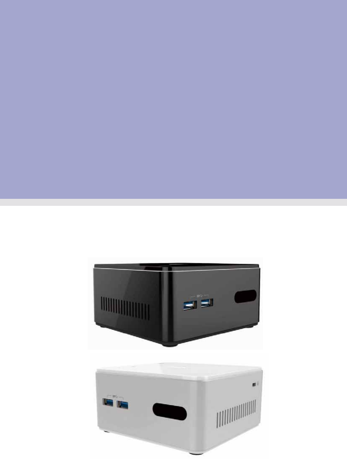
Packing List
Before setting up the system, check that the items listed below are included and in good
condition. If any items are missing, please contact your dealer immediately.
ECS SI mPC x1
Adapter x1
User Manual x1
Antenna x2 (Optional)
VESA Mount Bracket x1 (Optional)
50-60Hz, 0.9A max,
v ECS SI mPC
Safety Instructions
1. Read these safety instructions carefully.
2. Keep this User Manual for later reference.
3. Disconnect this equipment from any AC outlet before cleaning. Use a damp cloth.
Do not use liquid or spray detergents for cleaning.
4. For plug-in equipment, the power outlet socket must be located near the equipment
and must be easily accessible.
5. Keep this equipment away from humidity.
6. Put this equipment on a reliable surface during installation. Dropping it or letting it fall
may cause damage.
7. The openings on the enclosure are for air convection. Protect the equipment from
overheating. DO NOT COVER THE OPENINGS.
8. Make sure the voltage of the power source is correct before connecting the
equipment to the power outlet.
9. Position the power cord so that people cannot step on it. Do not place anything over
the power cord.
10. All cautions and warning on the equipment should be noted.
11. If the equipment is not used for a longt time, discounnect it from the power source to
avoid damage by transient overvoltage.
12. Never pour any liquid into an opening. This may cause fire or electrical shock.
13. Never open the equipment. For safety reasons, the equipment should be opened only
by qualified service personnel.
14. If one of the following situations arises, get the equipment checked by service
personnel:
a. The power cord or plug is damaged.
b. Liquid has penetrated into the equipment.
c. The equipment has been exposed to moisture.
d. The equipment does not work well, or you cannot get it to work according to the
user’s manual.
e. The equipment has been dropped and damaged.
f. The equipment has obvious signs of breakage.
15. DO NOT LEAVE THIS EQUIPMENT IN AN ENVIRONMENT WHERE THE STORAGE
TEMPERATURE MAY GO BELOW -20° C (-4° F) OR ABOVE 60° C (140° F). THIS
COULD DAMAGE THE EQUIPMENT. THE EQUIPMENT SHOULD BE IN A
CONTROLLED ENVIRONMENT.
16. If your computer is losing time significantly or the BIOS configuration resets itself
to be default, the battery may have no power.
17. IMPROPER INSALLATION OF VESA MOUNTING CAN RESULT IN SERIOUS
PERSONAL INJURY! VESA mount installation should be performed by a
professional technician; please contact the service technician or your retailer if you
need this service.
18. Maintenace: to properly maintain and clean the surfaces, use only the approved
products or clean with a dry applicator.
ECS SI mPC vi
Contents
Chapter 1 System Information .............................1
1.1 Introduction ................................................................................................ 2
1.2 Specifications ............................................................................................. 2
1.3 Cleaning/Disinfecting ................................................................................. 3
Chapter 2 Getting Started ....................................4
2.1 System Tour
Figure 2.1 Top View ..................................................................... 5
Figure 2.2 Bottom View ................................................................ 5
2.2 Distribution Description ..……………………………………………………… 7
Chapter 3 Hardware Installation .........................8
3.1 Motherboard Introduction ....................................................................... 9
3.2 Installing the Motherboard .……..….…………………...….…..………....... 12
Chapter 4 Using BIOS ........................................20
4.1 About the Setup Utility ............................................................................. 21
4.2 Using BIOS …………………………………………………………………… 22
Figure 2.3 Side View .................................................................... 5
Figure 2.4 I/O Side View............................................................... 6
2.3 Powering the System ..………………………………………………………… 7
............................................................................................... 5
vii ECS SI mPC
Chapter 5 Feature Inforamtion .........................39
5.1 Introduction ............................................................................................. 40

Chapter 1
1 System Information

1.1 Introduction
The product has onboard Intel® Bay Trail-M SoC for personal micro desktop markets or
educational usage.
Below is a brief summary of the computer’s many feature:
1.2 Specifications
ECS SI mPC 2
Item Description
CPU/SoC Intel® Bay Trail-M SoC Celeron N2830
TDP 7.5W
Memory
Expansion Slot
Storage 1 x SATA 3GB/s Connector
Audio Chip Realtek ALC283-CG
LAN Chip
Front Port I/O 2 x USB 3.0 ports (Type-A)
1 x IR
Rear I/O
1 x HDMI port (A type)
1 x RJ45 LAN connector
2 x USB 2.0 ports
1 x 12V DC jack
1 x Audio jack (Mic In/Line out)
Internal I/O
connectors & headers
1 x DDR3L SO-DIMM socket, Max 8GB
1 x Half-size mini-PCIe slot (supports mSATA, USB &
PCIe signal)
10/100/1000 Mbps support (Ethernet port), Realtek
RTL8111G
1 x 4-pin CPU FAN
1 x Serial ATA 3Gb/s connector
1 x 5-pin SATA PWR connector
1 x 2-pin Battery connector
1 x 3-pin CLR CMOS
1 x Power ON LED
1 x Logo LED header
1 x 2-pin Wireless charger header (Not Support)
1 x 4-pin Speaker
1 x 8-pin NFC header
Form Factor mPC-A 116.6*112*45.6 mm 0.595L
mPC-AH 116.6*112*55.6 mm 0.726L
Optional Device Storage type: 2.5” HDD, Half-size mini-PCIe mSATA
SSD, SATADOM
WLAN: 802.11b/g/n + Bluetooth4.0
NFC: URAT interface
Wireless Charger: Compatible with Qi (Not Support)
Speaker: Internal speaker 1Wx2
NOTE:
The features listed in this section is for your reference only. The exact configuration of
the system depends on the model purchased.
System BIOS 64Mb SPI ROM

Item Description
Adapter ASIAN POWER DEVICES INC. 12V, 3A, 36W
WA-36A12FU-AAAM
WA-36A12FG-AAAA
WA-36A12FK-AAAA
WA-36A12FS-AAAA
WA-36A12FN-AAAA
KUANTECH INCORPORATED COMPANY 12V, 3A, 36W
KSAS0361200300D5
KSAS0361200300HU
KSAS0361200300HE
KSAS0361200300HK
KSAS0361200300HA
1.3 Cleaning/Disinfecting
During normal use ECS SI mPC may become solied and should, therefore, be cleaned
regularly.
Steps:
1. Wipe ECS SI mPC with a clean cloth that has been moistened in the cleaning solution.
2. Prepare agent per manufacturer’s instructions or hospital protocol.
3. Wipe thoroughly with a clean cloth.
Caution! Do not immerse or rinse ECS SI mPC or its peripherals. If you accidentally spill
liquid on the device, disconnect the unit from the power source. Contact your
Biomed personnel regarding the continued safety of the unit before placing it
back in operation.
Do not spray cleaning agent on the chassis.
Do not use disinfectants that contain phenol.
Do not autoclave or clean ECS SI mPC or its peripherals with strong aromatic,
chlorinated, ketone, ether, or other solvents, sharp tools or abrasives. Never
immerse electrical connectors in water or other liquids.
Attention!
Ne pas immerger ou rincer ECS SI mPC ou ses périphériques. Si vous
renversez par accident un liquide sur l'appareil, débranchez l'appareil de la
source d'alimentation. Contactez votre Biomed concernant la sécurité
continue de l'unité avant de la remettre en service.
Ne pas pulvériser l'agent de nettoyage sur le châssis.
Ne pas utiliser de désinfectants contenant du phénol.
Ne pas passer à l'autoclave ou ECS SI mPC propre ou ses périphériques avec
fortes, cétone, éther, ou d'autres solvants, des outils tranchants ou abrasifs
aromatiques chlorés. Ne jamais plonger connecteurs électriques dans l'eau
ou d'autres liquids.
3 ECS SI mPC

Chapter 2
2 Getting Started
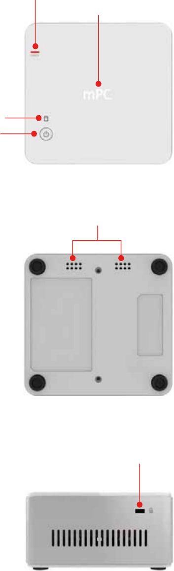
2.1 System Tour
Before you start to set up system, take a moment to become familiar with the
location sand purposes of the controls, drives, connections and ports, which are
illustrated in the figures below.
Figure 2.1 Top View
Figure 2.2 Bottom View
Figure 2.3 Side View
Wireless charger LED (Optional)
(Power transfer Green blink, Fault Red blink)
HDD LED
Power
Button
Wireless charger/NFC (Optional)
Speaker (Optional)
Kensington Lock
5 ECS SI mPC
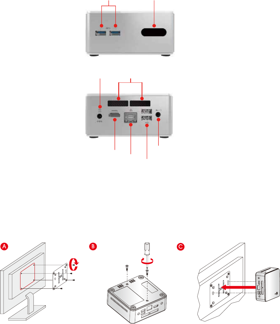
ECS SI mPC 6
USB 3.0 IR sensor
USB 2.0
Combo Audio Jack
(Mic In& Line out)
DC Jack
HDMI RJ45 port
Thermal opening
Figure 2.4 IO Side View
Install the VESA Mount
ECS SI mPC
2.2 Distri ution Description
The operating system is based on Windows .1 64bit / FreeDOS.
2.3 owering the System
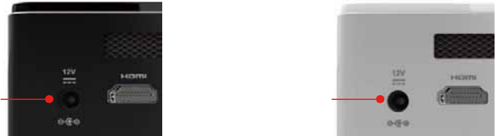
Connecting a 12 adapter to the DC-In ack, the system will start up automatically.
Figure 1: Location of DC-In ack.
DC-In DC-In

Chapter 3
2ardware Installation
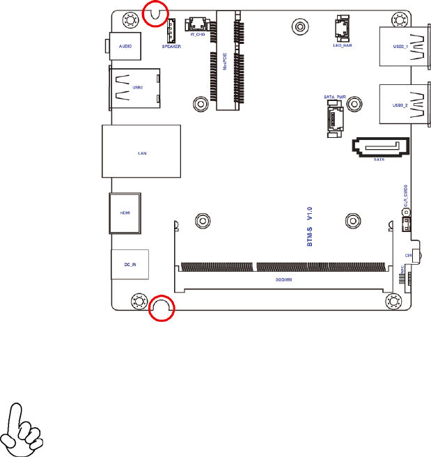
other oard Components
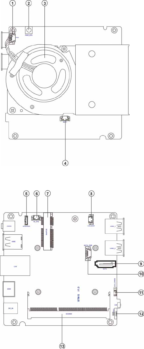
3.1 other oard Introduction
ECS SI mPC
a le o Mothe oa Co onents
lo ia a
BC
O
O
TS
1. FAN
2.
PWR BTN
3
.
System Fan
System Fan
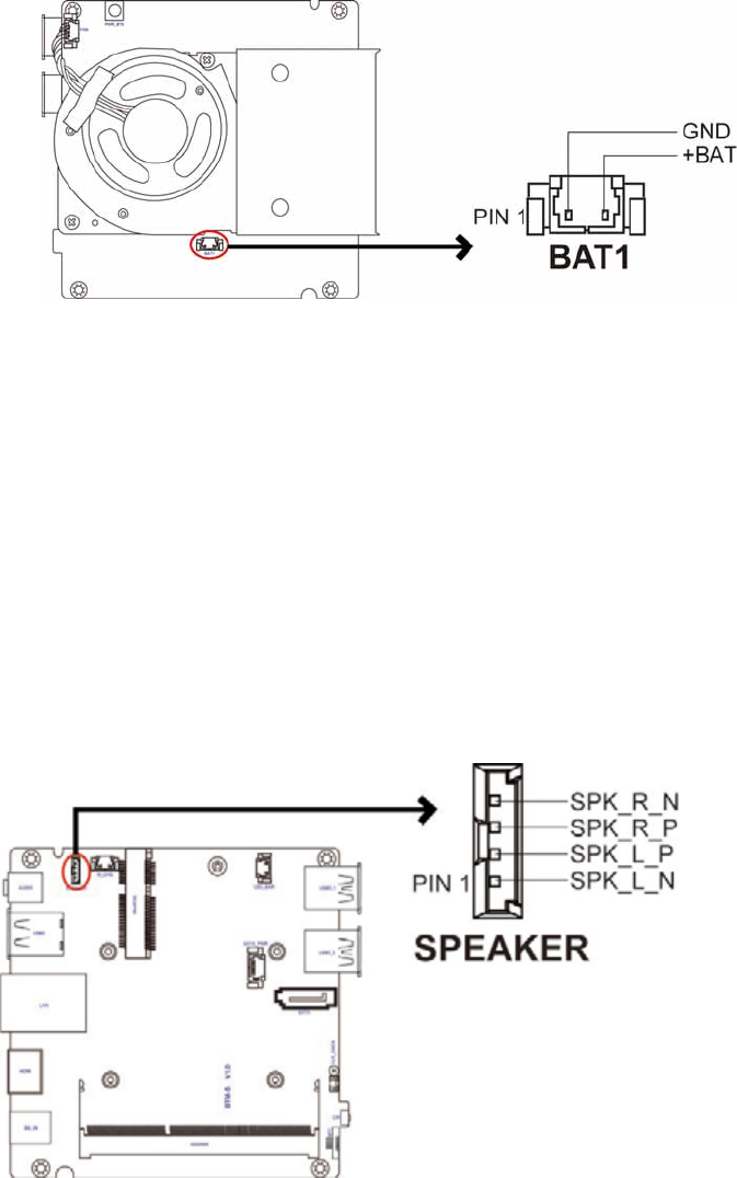
4. BAT1
5. SPEAKER
5
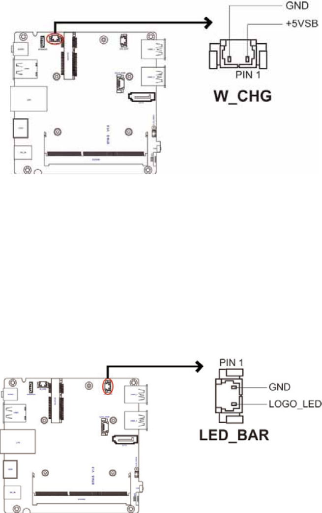
. W CHG
6
.
MiniPCIE
.
LED BAR
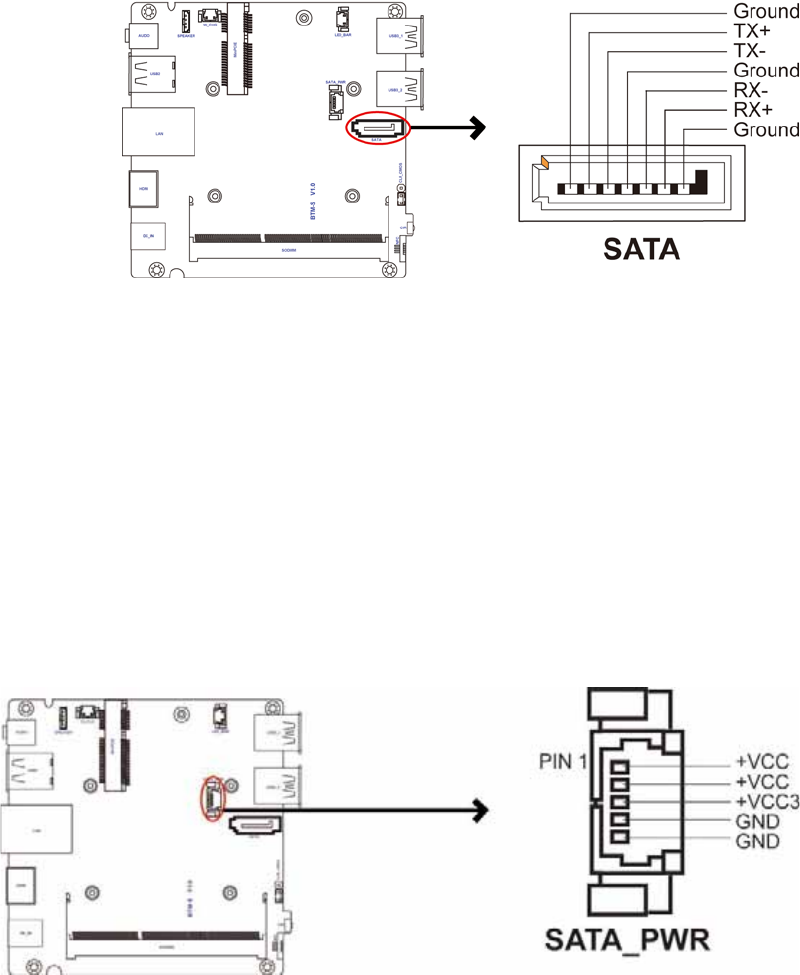
.
SATA
.
SATA PWR
10.
CLR CMOS
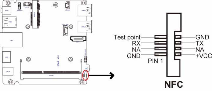
11. NFC
12.
SODIMM
System cooling fan connector
Power button
Battery connector
Speaker connector
Wireless charger connector
Logo LED connector
1 M.2 slot (half card supports mSATA, USB & PCIe signal)
Serial ATA connector
SATA power connector
Clear CMOS umper
NFC connector
204-pin DDR3 SDRAM SO-DIMM
10ECS SI mPC
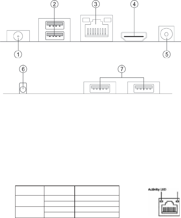
I/O orts
1. Com o udio ac ic In ine Out
Use the combo audio ack to connect the microphone, speaker or headphone.
2. SB2. orts
Use the USB 2.0 ports to connect USB 2.0 devices.
3. 4 ort
4. D I ort
Connect the display device to the HDMI port.
. DC 12V ac
Connect the DC IN ack to the power adapter.
.CI
It is coustomer IR sensor.
.SB3. orts
D Status Desc
r
iption
cti it
y
D
OFF
No
data
Orange
blinking Active
in
D
OFF
No
link
Green Link
Connect an RJ-45 ack to the LAN port to connect your computer to the Network.
Link
LED
ECS SI mPC
11
Use the USB 3.0 ports to connect USB 3.0 devices.
12ECS SI mPC
3.2 Installing the other oard
1. Safety Instructions
Follow these safety precautions when installing the motherboard:
Wear a grounding strap attached to a grounded device to avoid damage from static
electricity.
Discharge static electricity by touching the metal case of a safely grounded ob ect before
working on the motherboard.
Leave components in the static-proof bags.
Always remove the AC power by unplugging the power cord from the power outlet before
or removing the motherboard or other hardware components.
2. Installing the mother oard in a Chassis
1. Aim four locating holes of the BTM-S motherboard.
2. Use four screws to secure the motherboard.
Do not over-Ɵghten the screws as this can stress the motherboard.
ECS SI mPC
13
3. Installing ardware
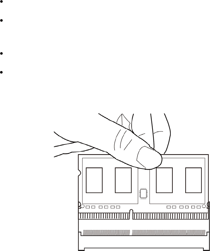
Installin Me o Mo ules
This motherboard accommodates one memory module. It can support one 204-pin
DDR3L 1333/1066 MH .
Do not remove any memory module from its antistatic packaging until you are ready
to install it on the motherboard. Handle the modules only by their edges. Do not
touch the components or metal parts. Always wear a grounding strap when you
handle the modules.
ou must install at least one module in any of the four slots. Total memory capacity
is GB.
Refer to the following to install the memory modules.
Install the DIMM module into the slot and press it firmly down until it seats correctly.
Check that the cutouts on the DIMM module edge connector match the notches in the
DIMM slot.
SODI
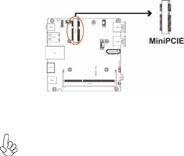
The slots on this motherboard are designed to hold expansion cards and connect them to
the system bus. Expansion slots are a means of adding or enhancing the motherboard’s
features and capabilities. With these efficient facilities, you can increase the
motherboard’s capabilities by adding hardware that performs tasks that are not part of
the basic system.
ini CI Slot The mini PCI Express x1 slot is for extending usage which supports half-card, and it supports
mSATA, USB & PCIe signal.
Before installing an add on card, check the documentation for the card carefully. If the card is not Plug and Play,
you may have to manually configure the card before installation.
Installin A on Ca s
14ECS SI mPC
ECS SI mPC
15
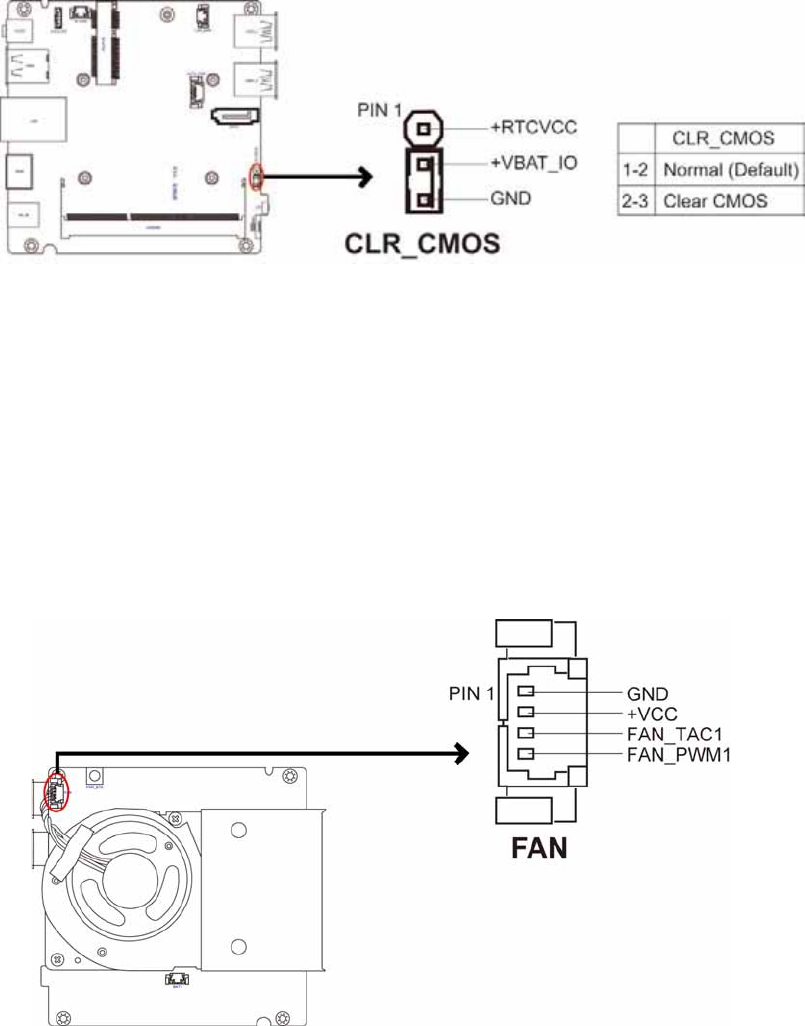
This section explains how to set umpers for correct configuration of the
motherboard.
Conne tin tional
eies
Refer to the following for information on connecting the motherboard’s devices.
Connect the system cooling fan to the FAN connector.
1. F System cooling fan connector
Che in u e Settin s
16ECS SI mPC
3. S Spea er connector
2. B T1 Battery connector
ECS SI mPC
1
4. C G ireless charger connector
. D B ogo D connector
1ECS SI mPC
. S T S T power connector
. S T Serial T connector
ECS SI mPC19
8. NFC: NFC connector