ELITEGROUP COMPUTER SYSTEMS MPC Personal Computer User Manual ECS SI mPC 2
ELITEGROUP COMPUTER SYSTEMS CO., LTD Personal Computer ECS SI mPC 2
Contents
- 1. User Manual-Part 1
- 2. User Manual-Part 2
User Manual-Part 2

Chapter 4
1 Using BIOS
ECS SI mPC
21
4.1 About the Setup Utility
The computer uses the latest “American Megatrends Inc.” BIOS with support for Windows Plug and
Play. The CMOS chip on the motherboard contains the ROM setup instructions for configuring the
motherboard BIOS.
The BIOS (Basic Input and Output System) Setup Utility displays the system’s configuration status and
provides you with options to set system parameters. The parameters are stored in battery-backed-up
CMOS RAM that saves this information when the power is turned off. When the system is turned back
on, the system is configured with the values you stored in CMOS.
The BIOS Setup Utility enables you to configure:
• Hard drives, diskette drives and peripherals
• Video display type and display options
• Password protection from unauthorized use
• Power Management features
The settings made in the Setup Utility affect how the computer performs. Before using the Setup Utility,
ensure that you understand the Setup Utility options.
This chapter provides explanations for Setup Utility options.
A standard configuration has already been set in the Setup Utility. However, we recommend that you
read this chapter in case you need to make any changes in the future.
This Setup Utility should be used:
1. The Standard Configuration
When you power on the system, BIOS enters the Power-On Self Test (POST) routines. POST is a
series of built-in diagnostics performed by the BIOS. After the POST routines are completed, the
following message appears:
2. Entering the Setup Utility
• when changing the system configuration
• when a configuration error is detected and you are prompted to make changes to the Setup
Utility
• when trying to resolve IRQ conflicts
• when making changes to the Power Management configuration
• when changing the password or making other changes to the Security Setup

22ECS SI mPC
Press the delete key to access BIOS Setup Utility.
Press DEL to enter SETUP
Aptio Setup Utility - Copyright (C) 2013 American Megatrends, Inc.
Version 2.16.1242. Copyright (C) 2013 American Megatrends, Inc.
Main
BIOS Information
System Date [Tue 07/28/2015]
System Time [10:20:36]
Set the Date. Use Tab to
switch between Date
elements.
Enter: Select
+/-: Change Opt.
F1: General Help
F2: Previous Values
F3: Optimized Defaults
F4: Save & Exit
ESC: Exit
: Select Screen
: Select Item
4.2 Using BIOS
When you start the Setup Utility, the main menu appears. The main menu of the Setup Utility displays
a list of the options that are available. A highlight indicates which option is currently selected. Use the
cursor arrow keys to move the highlight to other options. When an option is highlighted, execute the
option by pressing <Enter>.
Some options lead to pop-up dialog boxes that prompt you to verify that you wish to execute that option.
Other options lead to dialog boxes that prompt you for information.
Some options (marked with a triangle )lead to submenus that enable you to change the values for the
option. Use the cursor arrow keys to scroll through the items in the submenu.
In this manual, default values are enclosed in parenthesis. Submenu items are denoted by a triangle .
The default BIOS seng for this motherboard apply for most condions with opmum performance.
We do not suggest users change the default values in the BIOS setup and take no responsibility to
any damage caused by changing the BIOS sengs.
ECS SI mPC
23
ESC Exit the current menu
Save & Exit
Optimized Defaults
Previous Value
General Help
Select
Change Opt.
Scrolls through the items on a menu
+/-
Enter
F1
F2
F3
F4
For the purpose of beer product maintenance, the manufacture reserves the right to change
the BIOS items presented in this manual. The BIOS setup screens shown in this chapter are for
reference only and may differ from the actual BIOS. Please visit the manufacture’s website
for updated manual.
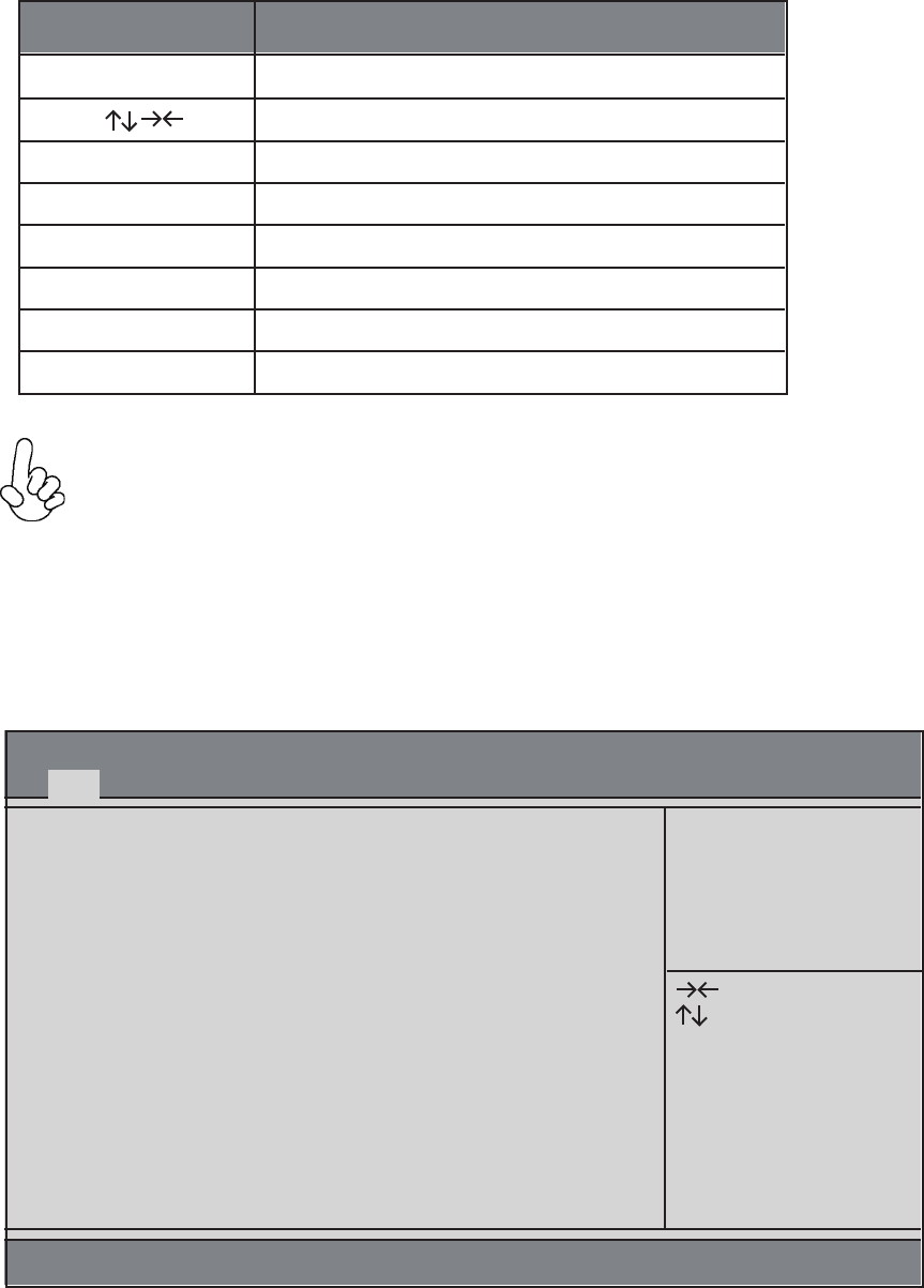
The BIOS navigation keys are listed below:
1. BIOS Navigation Keys
KEY FUNCTION
When you enter the BIOS Setup program, the main menu appears, giving you an overview of
the basic system information. Select an item and press <Enter> to display the submenu.
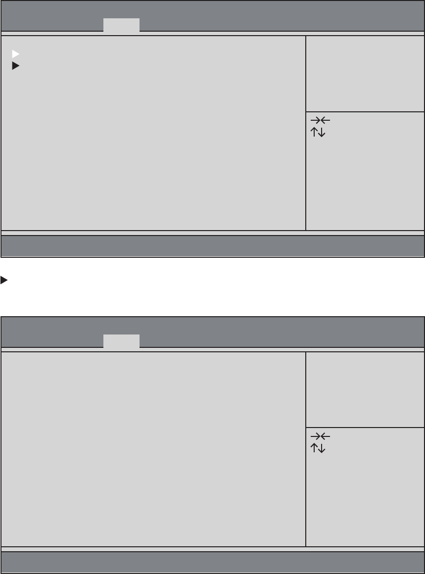
2. Main Menu
Aptio Setup Utility - Copyright (C) 2013 American Megatrends, Inc.
Version 2.16.1242. Copyright (C) 2013 American Megatrends, Inc.
Main
BIOS Information
System Date [Tue 07/28/2015]
System Time [10:20:36]
Set the Date. Use Tab to
switch between Date
elements.
Enter: Select
+/-: Change Opt.
F1: General Help
F2: Previous Values
F3: Optimized Defaults
F4: Save & Exit
ESC: Exit
: Select Screen
: Select Item
The Date and Time items show the current date and time on the computer. If you are running a
Windows OS, these items are automatically updated whenever you make changes to the Windows
Date and Time Properties utility.
System Date & Time
24ECS SI mPC
This page sets up more advanced information about your system. Handle this page with caution.
Any changes can affect the operation of your computer.
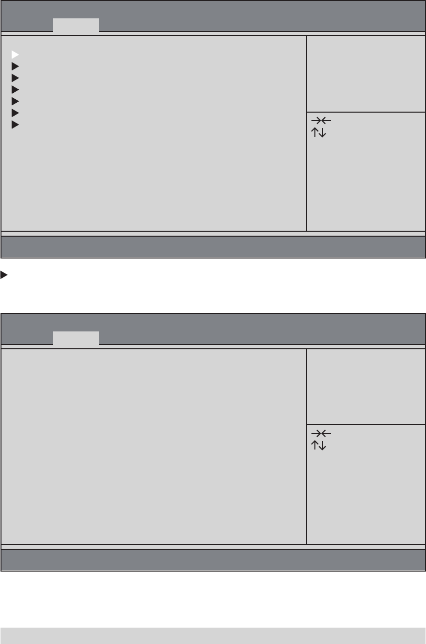
3. Advanced Menu
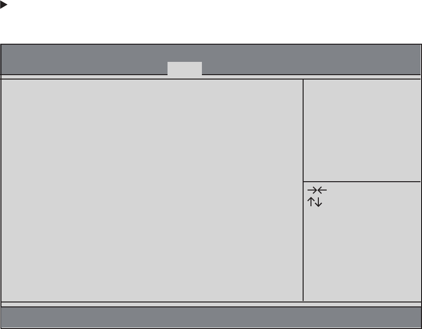
The item in the menu shows the LAN-related information that the BIOS automatically detects.
LAN Configuration
Aptio Setup Utility - Copyright (C) 2013 American Megatrends, Inc.
Version 2.16.1242. Copyright (C) 2013 American Megatrends, Inc.
Advanced
LAN Configuration
Power Management Setup
PC Health Status
ACPI Settings
CPU Configuration
SATA Configuration
USB Configuration
LAN Configuration
Parameters
Enter: Select
+/-: Change Opt.
F1: General Help
F2: Previous Values
F3: Optimized Defaults
F4: Save & Exit
ESC: Exit
: Select Screen
: Select Item
Aptio Setup Utility - Copyright (C) 2013 American Megatrends, Inc.
Version 2.16.1242. Copyright (C) 2013 American Megatrends, Inc.
Advanced
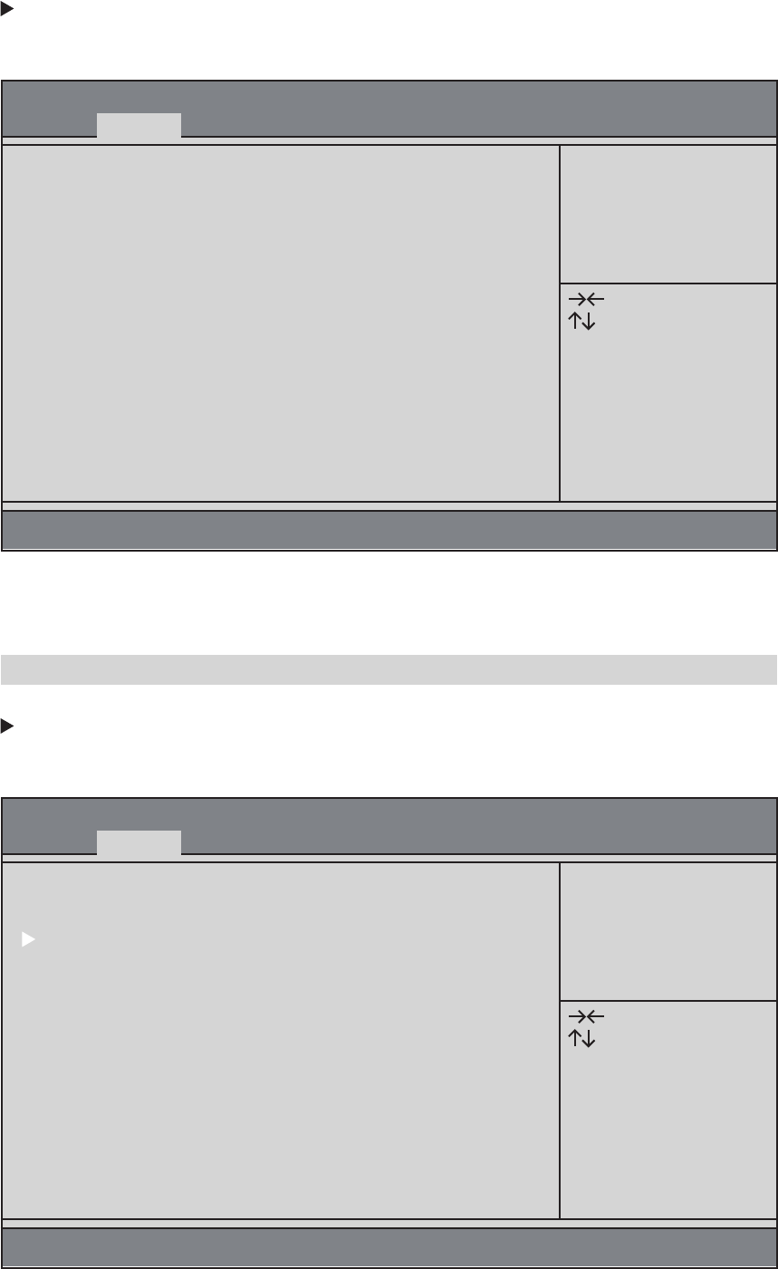
LAN Configuration
Onboard LAN Controller [Enabled]
Enabled/Disabled
Onboard LAN 1
Controller
Enter: Select
+/-: Change Opt.
F1: General Help
F2: Previous Values
F3: Optimized Defaults
F4: Save & Exit
ESC: Exit
: Select Screen
: Select Item
Use this item to enable or disable the Onboard LAN.
Onboard LAN Controller (Enabled)
Press <Esc> to return to the Advanced Menu page.

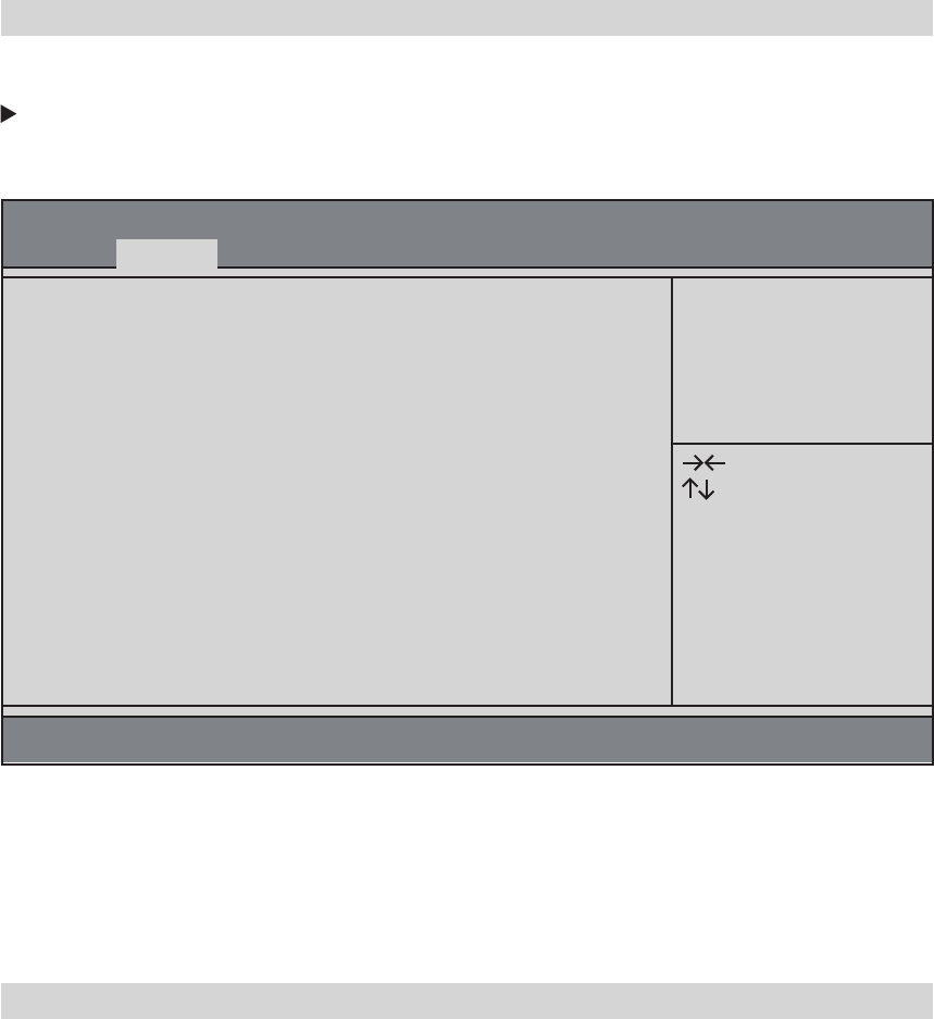
This page sets up some parameters for system power management operation.
Power Management Setup
Aptio Setup Utility - Copyright (C) 2013 American Megatrends, Inc.
Version 2.16.1242. Copyright (C) 2013 American Megatrends, Inc.
Advanced
Power Management Setup
Resume from LAN [Enabled]
Resume By PME [Disabled]
Resume By USB [Enabled]
Resume By RTC Alarm [Disabled]
EUP Function [Enabled]
Resume from LAN1 Help
Enter: Select
+/-: Change Opt.
F1: General Help
F2: Previous Values
F3: Optimized Defaults
F4: Save & Exit
ESC: Exit
: Select Screen
: Select Item
Use this item to enable or disable resume from LAN.
Resume from LAN (Enabled)
The system can be turned off with a software command. If you enable this item, the system can
automatically resume if there is an incoming call on the PCI/PCI-E Modem or PCI/PCI-E LAN card.
You must use an ATX power supply in order to use this feature. Use this item to do wake-up action
if inserting the PCI/PCI-E card.
Resume By PME (Disabled)
This item allows you to enable or disable the USB device wakeup function from S3 mode.
Resume By USB (Enabled)
The system can be turned off with a software command. If you enable this item, the system can
automatically resume at a fixed time based on the system’s RTC (realtime clock). Use the item below
this one to set the date and time of the wake-up alarm. You must use an ATX power supply in order
to use this feature.
Resume By RTC Alarm (Disabled)
This item allows you to enable or disable EUP function.
EUP Function (Enabled)
Press <Esc> to return to the Advanced Menu page.
ECS SI mPC
25

This motherboard supports hardware monitoring, this item lets you monitor the parameters for
critical voltages, temperatures and fan speeds.
PC Health Status
Aptio Setup Utility - Copyright (C) 2013 American Megatrends, Inc.
Version 2.16.1242. Copyright (C) 2013 American Megatrends, Inc.
Advanced
PC Health Status
Smart Fan Function
System Temperature 30℃
CPU Temperature 34℃
CPU Fan Speed 920 RPM
VCore 0.996V
DIMM Voltage 1.380V
+12V 12.240V
VCC 5.040V
VCC3 3.336V
Select the highest ACPI
sleep state the system
will enter when the
SUSPEND button is
pressed.
Enter: Select
+/-: Change Opt.
F1: General Help
F2: Previous Values
F3: Optimized Defaults
F4: Save & Exit
ESC: Exit
: Select Screen
: Select Item
Press <Esc> to return to the Advanced Menu page.
These items display the monitoring of the overall inboard hardware health events, sucha as CPU &
DIMM voltage, CPU & System fan speed...etc.
System Component Characteristics
• System Temperature
• CPU Temperature
• CPU Fan Speed
• VCore
• DIMM Voltage
• +12V
• VCC
• VCC3
26ECS SI mPC
This item allows you to enter the APCI S3 (Suspend to RAM) Sleep State (default).
ACPI Sleep State (S3 (Suspend to RAM))
This item in the menu shows the highest ACPI sleep state when the system enters suspend.
ACPI Settings
Aptio Setup Utility - Copyright (C) 2013 American Megatrends, Inc.
Version 2.16.1242. Copyright (C) 2013 American Megatrends, Inc.
Advanced
ACPI Settings
ACPI Sleep State [S3 (Suspend to RAM)]
Select the highest ACPI
sleep state the system
will enter when the
SUSPEND button is
pressed.
Enter: Select
+/-: Change Opt.
F1: General Help
F2: Previous Values
F3: Optimized Defaults
F4: Save & Exit
ESC: Exit
: Select Screen
: Select Item
The item in this menu shows the CPU configuration.
CPU Configuration
Aptio Setup Utility - Copyright (C) 2013 American Megatrends, Inc.
Version 2.16.1242. Copyright (C) 2013 American Megatrends, Inc.
Advanced
CPU Configuration
Socket 0 CPU Information
CPU Speed 2.16 GHz
64-bit Supported
Limit CPUID Maximum [Disabled]
Execute Disable Bit [Enabled]
Intel Virtualization Technology [Enabled]
Power Technology [Energy Efficient]
Socket specific CPU
Information
Enter: Select
+/-: Change Opt.
F1: General Help
F2: Previous Values
F3: Optimized Defaults
F4: Save & Exit
ESC: Exit
: Select Screen
: Select Item
Press <Esc> to return to the Advanced Menu page.
ECS SI mPC
27

Scroll to this item and press <Enter> to view the following screen:
Socket 0 CPU Information
Aptio Setup Utility - Copyright (C) 2013 American Megatrends, Inc.
Version 2.16.1242. Copyright (C) 2013 American Megatrends, Inc.
Advanced
Socket 0 CPU Information
Intel(R) Celeron(R) CPU N2830 @ 2.16GHz
CPU Signature 30678
Microcode Patch 815
Max CPU Speed 2168 MHz
Min CPU Speed 500 MHz
Processor Cores 2
Intel HT Technology Not Supported
Intel VT-x Technology Supported
L1 Data Cache 24 KB x 2
L1 Code Cache 32 KB x 2
L2 Cache 1024 KB x 1
L3 Cache Not Present
Select the highest ACPI
sleep state the system
will enter when the
SUSPEND button is
pressed.
Enter: Select
+/-: Change Opt.
F1: General Help
F2: Previous Values
F3: Optimized Defaults
F4: Save & Exit
ESC: Exit
: Select Screen
: Select Item
Press <Esc> to return to the CPU Configuration page.
This item shows the information of the CPU signature.
CPU Signature (30678)
This item shows the version of microcode patch.
Microcode Patch (815)
This item shows the max speed of the CPU.
Max CPU Speed (2168 MHz)
This item shows the min speed of the CPU.
Min CPU Speed (500 MHz)
This item shows the number of cores of the processor.
Processor Cores (2)
This item shows the computer supports Intel HT technology or not.
Intel HT Technology (Not Supported)
This item shows the computer supports Intel VT-x technology or not.
Intel VT-x Technology (Supported)
This item shows the size of CPU L1 Data Cache memory.
LI Data Cache (24 KB x 2)
This item shows the size of CPU L1 Code Cache memory.
LI Code Cache (32 KB x 2)
These items show the size of CPU L2/L3 Cache memory.
L2/L3 Cache (1024KB x 1/Not Present)
This is display-only field and displays the information of the CPU installed in your computer.
Intel(R) Celeron(R) CPU N2830 @ 2.16GHz
28ECS SI mPC
This item shows the processor speed.
CPU Speed (2.16 GHz)
This item shows the computer supports 64-bit.
64-bit (Supported)
Use this item to show the mode of Serial ATA configuration options.
SATA Configuration
Aptio Setup Utility - Copyright (C) 2013 American Megatrends, Inc.
Version 2.16.1242. Copyright (C) 2013 American Megatrends, Inc.
Advanced
SATA Configuration
SATA Mode [AHCI Mode]
mSATA Port Not Present
SATA Port Not Present
Select IDE / AHCI
Enter: Select
+/-: Change Opt.
F1: General Help
F2: Previous Values
F3: Optimized Defaults
F4: Save & Exit
ESC: Exit
: Select Screen
: Select Item
Use this item to select SATA mode.
SATA Mode (AHCI Mode)
This motherboard supports one mSATA and one SATA channel, and each channel allows one mSATA
/SATA device to be installed. Use these items to configure each device on the mSATA/SATA channel.
mSATA/SATA Port (Not Present)
Press <Esc> to return to the Advanced Menu page.
Press <Esc> to return to the Advanced Menu page.
Use this item to enable or disable the maximum CPUID value limit, you can enable this item to
prevent the system from “rebooting ” when trying to install Windows NT 4.0.
Limit CPUID Maximum (Disabled)
This item allows the processor to classify ares in memory by where application code can execute
and where it cannot. When a malicious worm attempts to insert code in the buffer, the processor
disables code execution, preventing damage or worm propagation. Replacing older computers with
Execute Disable Bit enabled systems can halt worm attacks, reducing the need for virus related
repair.
Execute Disable Bit (Enabled)
When disabled, a VMM cannot utilize the additional hardware capabilities provided by Vandor Pool
Technology.
Intel Virtualization Technology (Enabled)
Use this item to control the Energy mode of the processor.
Power Technology (Energy Efficient)
ECS SI mPC
29

Use this item to show the information of USB configuration.
USB Configuration
Aptio Setup Utility - Copyright (C) 2013 American Megatrends, Inc.
Version 2.16.1242. Copyright (C) 2013 American Megatrends, Inc.
Advanced
USB Configuration
All USB Devices [Enabled]
Legacy USB Support [Enabled]
XHCI Mode [Auto]
External USB3.0 Device [Enabled]
USB Support Parameters
Enter: Select
+/-: Change Opt.
F1: General Help
F2: Previous Values
F3: Optimized Defaults
F4: Save & Exit
ESC: Exit
: Select Screen
: Select Item
Use this item to enable or disable all USB devices.
All USB Devices (Enabled)
Use this item to enable or disable support for legacy USB devices.
Legacy USB Support (Enabled)
Use this item to enable or disable all USB XHCI mode.
XHCI Mode (Auto)
Use this item to enable or disable external USB 3.0 device.
External USB3.0 Device (Enabled)
30ECS SI mPC
The chipset menu items allow you to change the settings for the SoC chip and other system.
4. Chipset Menu
Scroll to this item and press <Enter> to view the following screen:
SoC Configuration
This item is used to select DVMT 5.0 Pre-Allocated (Fixed) Graphics Memory size used by the Internal
Graphics Device.
DVMT Pre-Allocated (64M)
This item is used to select DVMT 5.0 and Graphics Memory size used by the Internal Graphics Device.
DVMT Total Gfx Mem (256MB)
Aptio Setup Utility - Copyright (C) 2013 American Megatrends, Inc.
Version 2.16.1242. Copyright (C) 2013 American Megatrends, Inc.
Chipset
SoC Configuration
TXE Information
CPU Shutdown Temperature [Disabled]
LOGO LED [Enabled]
SoC Parameters
Enter: Select
+/-: Change Opt.
F1: General Help
F2: Previous Values
F3: Optimized Defaults
F4: Save & Exit
ESC: Exit
: Select Screen
: Select Item
Aptio Setup Utility - Copyright (C) 2013 American Megatrends, Inc.
Version 2.16.1242. Copyright (C) 2013 American Megatrends, Inc.
Chipset
SoC Configuration
DVMT Pre-Allocated [64M]
DVMT Total Gfx Mem [256MB]
Restore AC Power Loss [Power Off]
Audio Configuration
Azalia HD Audio [Enabled]
Azalia Internal HDMI Codec [Enabled]
Select DVMT 5.0
Pre-Allocated (Fixed)
Graphics Memory size
used by the Internal
Graphics Device.
Enter: Select
+/-: Change Opt.
F1: General Help
F2: Previous Values
F3: Optimized Defaults
F4: Save & Exit
ESC: Exit
: Select Screen
: Select Item
ECS SI mPC
31

This item enables your computer to automatically restart or return to its operating status.
Restore AC Power Loss (Power Off)
This item enables or disables Azalia Internal HDMI Codec.
Azalia Internal HDMI Codec (Enabled)
This item enables or disables Azalia HD Audio.
Azalia HD Audio (Enabled)
Press <Esc> to return to the Chipset Menu page.
32ECS SI mPC

Scroll to this item and press <Enter> to view the following screen:
TXE Information
This item shows the Sec Reference Code version.
Sec RC Version (00.05.00.00)
This item shows the TXE Firmware version.
TXE FW Version (01.01.00.1089)
This item enables or disables CPU shutdown temperature.
CPU Shutdown Temperature (Disabled)
This item enables or disables LOGO LED.
LOGO LED (Enabled)
This is TXE mode control item, it is used to enable or disable the TXE firmware.
TXE Mode (Enabled)
Aptio Setup Utility - Copyright (C) 2013 American Megatrends, Inc.
Version 2.16.1242. Copyright (C) 2013 American Megatrends, Inc.
Chipset
TXE Information
Sec RC Version 00.05.00.00
TXE FW Version 01.01.00.1089
TXE Mode [Enabled]
Enable/Disable TXE
Firmware
Enter: Select
+/-: Change Opt.
F1: General Help
F2: Previous Values
F3: Optimized Defaults
F4: Save & Exit
ESC: Exit
: Select Screen
: Select Item
Press <Esc> to return to the Chipset Menu page.
ECS SI mPC
33

34ECS SI mPC
This page enables you to set the keyboard NumLock state and devices boot sequence.
5. Boot Menu
This item is used to select the operation system.
Operation System Select (Windows 7 or othe...)
This item enables or disables launch network option ROM.
Launch Network OpROM (Disabled)
This item enables or disables launch storage option ROM.
Launch Storage OpROM (Disabled)
This item enables or disables boot with initialization of a minimal set of device required to launch active
boot option. Has no effect for BBS boot options.
Fast Boot (Disabled)
This item enables you to select Numlock state.
Bootup Numlock State (On)
This item enables or disables quiet boot.
Quiet Boot (Disabled)
Use this item to select boot mode.
Boot Mode Select (LEGACY)
These items show the boot priorities.
Boot Option #1 /2 /3 /4 /5 /6 /7
Aptio Setup Utility - Copyright (C) 2013 American Megatrends, Inc.
Boot
Boot Configuration
Operation System Select [Windows 7 or othe...]
Launch Network OpROM [Disabled]
Launch Storage OpROM [Disabled]
Fast Boot [Disabled]
Bootup NumLock State [On]
Quiet Boot [Disabled]
Boot Mode Select [LEGACY]
Set Boot Priority
Boot Option #1 [Hard Disk]
Boot Option #2 [CD/DVD]
Boot Option #3 [USB/Floppy]
Boot Option #4 [USB CD/DVD]
Boot Option #5 [USB Hard Disk]
Boot Option #6 [USB Flash]
Boot Option #7 [Network]
Windows 7 or other OS:
Boot policy for Legacy OS
Windows 8.x: Boot policy
for UEFI OS without
Compatibility Support
Module (CSM)
Windows 8.x with CSM:
Boot policy for Windows
8.x with Compatibility
Support Module (CSM)
Enter: Select
+/-: Change Opt.
F1: General Help
F2: Previous Values
F3: Optimized Defaults
F4: Save & Exit
ESC: Exit
: Select Screen
: Select Item
Version 2.16.1242. Copyright (C) 2013 American Megatrends, Inc.

This page enables you to set setup administrator and password.
6. Security Menu
This item shows administrator password installed or not.
Administrator Password Status (Not Installed)
This item shows user password installed or not.
User Password Status (Not Installed)
Aptio Setup Utility - Copyright (C) 2013 American Megatrends, Inc.
Version 2.16.1242. Copyright (C) 2013 American Megatrends, Inc.
Administrator Password Status Not Installed
User Password Status Not Installed
Administrator Password
Secure Boot menu
Set Administrator
Password
Enter: Select
+/-: Change Opt.
F1: General Help
F2: Previous Values
F3: Optimized Defaults
F4: Save & Exit
ESC: Exit
: Select Screen
: Select Item
Security
ECS SI mPC
35
36ECS SI mPC
Scroll to this item and press <Enter> to view the following screen:
Secure Boot menu
This item shows system of secure boot (can be setup or user).
System Mode (Setup)
This item shows the active state of secure boot.
Secure Boot (Not Active/Disabled)
Aptio Setup Utility - Copyright (C) 2013 American Megatrends, Inc.
Version 2.16.1242. Copyright (C) 2013 American Megatrends, Inc.
System Mode Setup
Secure Boot Not Active
Secure Boot [Disabled]
Secure Boot can be
enabled if
1. System running in
User mode with enrolled
Platform Key(PK)
2. CSM function is
disabled
Enter: Select
+/-: Change Opt.
F1: General Help
F2: Previous Values
F3: Optimized Defaults
F4: Save & Exit
ESC: Exit
: Select Screen
: Select Item
Security

ECS SI mPC
37
This item enables you to save the changes that you have made and exit.
Save Changes and Exit
This item enables you to save the changes that you have made and reset.
Save Changes and Reset
This item enables you to discard any changes that you have made and exit.
Discard Changes and Exit
This item enables you to discard any changes that you have made and reset.
Discard Changes and Reset
This item enables you to save the changes that you have made.
Save Changes
This item enables you to discard any changes that you have made.
Discard Changes
This item enables you to restore the system defaults.
Restore Defaults
This item enables you to save the changes that you have made as user defaults.
Save as User Defaults
This item enables you to restore user defaults.
Restore User Defaults
Use this item to select the boot device.
Boot Override
This item enables you to save the options that you have made.
Save Options
This page enables you to exit system setup after saving or without saving the changes.
7. Exit Menu
Aptio Setup Utility - Copyright (C) 2013 American Megatrends, Inc.
Version 2.16.1242. Copyright (C) 2013 American Megatrends, Inc.
Save Changes and Exit
Discard Changes and Exit
Save Changes and Reset
Discard Changes and Reset
Save Options
Save Changes
Discard Changes
Restore Defaults
Save as User Defaults
Restore User Defaults
Boot Override
Exit system setup after
saving the changes.
Enter: Select
+/-: Change Opt.
F1: General Help
F2: Previous Values
F3: Optimized Defaults
F4: Save & Exit
ESC: Exit
: Select Screen
: Select Item
Exit
38ECS SI mPC
You can download and install updated BIOS for this motherboard from the manufacturer’s Website.
New BIOS provides support for new peripherals, improvements in performance, or fixes for known
bugs. Install new BIOS as follows
8. Updating the BIOS
1 If your motherboard has a BIOS protection jumper, change the setting to allow BIOS
flashing.
2 If your motherboard has an item called Firmware Write Protect in Advanced BIOS
features, disable it. (Firmware Write Protect prevents BIOS from being overwritten.)
3 Prepare a bootable device or create a bootable system disk. (Refer to Windows online
help for information on creating a bootable system disk.)
4 Download the Flash Utility and new BIOS file from the manufacturer’s Web site. Copy
these files to the bootable device.
5 Turn off your computer and insert the bootable device in your computer. (You might
need to run the Setup Utility and change the boot priority items on the Advanced
BIOS Features Setup page, to force your computer to boot from the bootable device
first.)
6 At the C:\ or A:\ prompt, type the Flash Utility program name and the file name of the
new BIOS and then press <Enter>. Example: AFUDOS.EXE 040706.ROM
7 When the installation is complete, remove the bootable device from the computer and
restart your computer. If your motherboard has a Flash BIOS jumper, reset the jumper
to protect the newly installed BIOS from being overwritten. The computer will restart
automatically.

Chapter 5
1 Feature Information
40ECS SI mPC
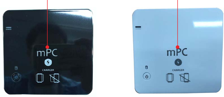
5.1 Introduction
The NFC and wireless charger is optional feature on this computer. Please refer to following
instructions.
1. Wireless charger (Not Support)
The Wireless charger specification that the computer support is compatible with Qi. Put the Rx
device on charger area for power transfer.
2. NFC
The NFC module that compatible with (1) ISO 15693 (2) ISO 14443A (3) ISO 14443B. Put the
device on the center of computer for read/write.
Wireless charger/NFC (Optional) Wireless charger/NFC (Optional)