ELITEGROUP COMPUTER SYSTEMS TRBC1CD1 Wireless Motherboard User Manual

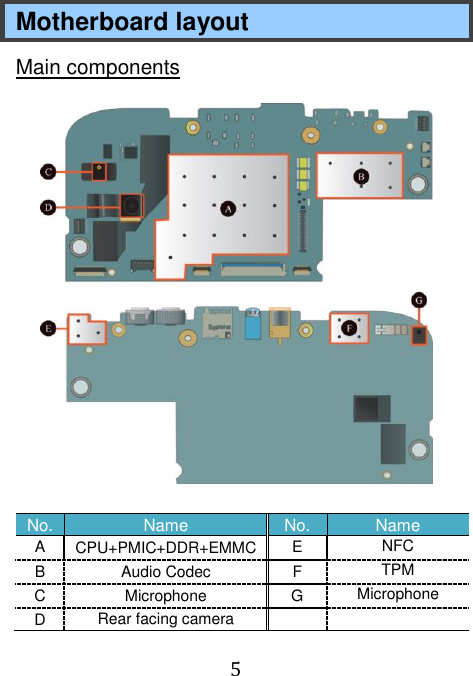
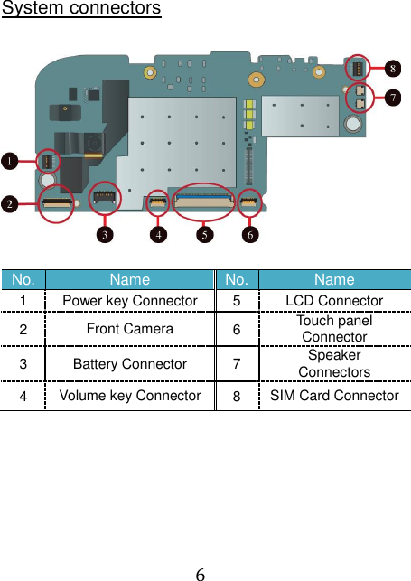
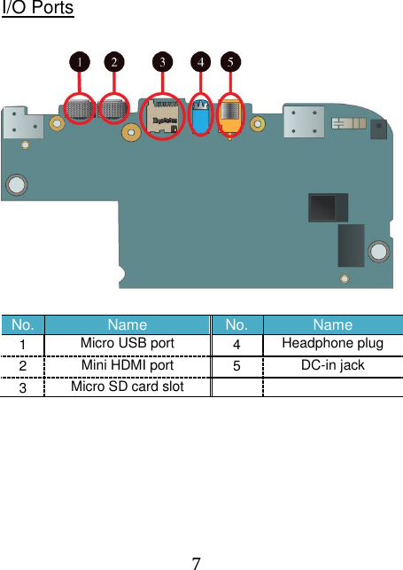
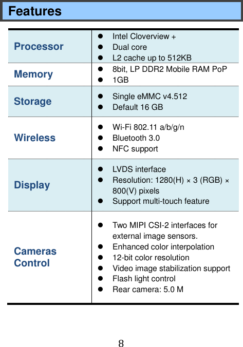
ELITEGROUP COMPUTER SYSTEMS CO., LTD Wireless Motherboard

User Manual

   TR10CD1 Motherboard Guide
 1  FEDERAL COMMUNICATIONS COMMISSION INTERFERENCE STATEMENT This equipment has been tested and found to comply with the limits for a Class B digital device, pursuant to part 15 of the FCC Rules. These limits are designed to provide reasonable protection against harmful interference in a residential installation. This equipment generates, uses and can radiate radio frequency energy and, if not installed and used in accordance with the instructions, may cause harmful interference to radio communications. However, there is no guarantee that interference will not occur in a particular installation. If this equipment does cause harmful interference to radio or television reception, which can be determined by turning the equipment off and on, the user is encouraged to try to correct the interference by one or more of the following measures:  Reorient or relocate the receiving antenna.  Increase the separation between the equipment and receiver.  Connect the equipment into an outlet on a circuit different from that to which the receiver is connected.  Consult the dealer or an experienced radio/ TV technician for help.  Operations in the 5.15-5.25GHz band are restricted to indoor usage only.   CAUTION: Any changes or modifications not expressly approved by the grantee of this device could void the user's authority to operate the equipment. This device complies with Part 15 of the FCC Rules. Operation is subject to the following two conditions: (1) this device may not cause harmful interference, and (2) this device must accept any interference received, including interference that may cause
 2 undesired operation.
 3  RF Exposure Information This device meets the government’s requirements for exposure to radio waves. This device is designed and manufactured not to exceed the emission limits for exposure to radio frequency (RF) energy set by the Federal Communications Commission of the U.S. Government.    End Product Labeling This transmitter module is authorized only for use in device where the antenna may be installed such that 20cm may be maintained between the antenna and users. The final end product must be labeled in a visible area with the following: "Contains FCC ID: WL6-TRBC1CD1”    Information for the OEMs and Integrators The following statement must be included with all versions of this document supplied to an OEM or integrator, but should not be distributed to the end user. 1) This device is intended for OEM integrators only. 2) Please see the full Grant of Equipment document for other restrictions. This radio transmitter FCC ID: WL6-TRBC1CD1 has been approved by FCC to operate with the antenna types listed below with the maximum permissible gain and required antenna impedance for each antenna type indicated. Antenna types not included in this list, having a gain greater than the maximum gain indicated for that type, are strictly prohibited for use with this device.   Antenna List
 4 No. Manufacturer Part No. Antenna Type Peak Gain 1 Pulse 02H475-006500 Ceramic Chip Antenna 3.2 dBi for 2.4GHz 4.2 dBi for 5 GHz Note: The antenna connector is I-PEX type.
 5 Motherboard layout Main components  No. Name No. Name A CPU+PMIC+DDR+EMMC   E NFC B Audio Codec F TPM C Microphone G Microphone D Rear facing camera
 6  System connectors   No. Name No. Name 1 Power key Connector 5 LCD Connector 2 Front Camera 6 Touch panel Connector 3 Battery Connector 7 Speaker    Connectors 4 Volume key Connector 8 SIM Card Connector
 7  I/O Ports   No. Name No. Name 1 Micro USB port 4 Headphone plug 2 Mini HDMI port 5 DC-in jack 3 Micro SD card slot
 8 Features Processor   Intel Cloverview +     Dual core   L2 cache up to 512KB Memory   8bit, LP DDR2 Mobile RAM PoP  1GB Storage  Single eMMC v4.512   Default 16 GB Wireless    Wi-Fi 802.11 a/b/g/n   Bluetooth 3.0  NFC support Display   LVDS interface   Resolution: 1280(H) × 3 (RGB) × 800(V) pixels     Support multi-touch feature Cameras Control     Two MIPI CSI-2 interfaces for external image sensors.   Enhanced color interpolation    12-bit color resolution     Video image stabilization support     Flash light control   Rear camera: 5.0 M
 9 Input/Output      1 x micro-USB 2.0, OTG port (Type A/B)   1 x Mic/head phone jack combo     1 x mini-HDMI (Type D)   1 x micro-SD card slot     1 x DC-in jack   Micro SIM card support Speaker & Mic    Build-in Speaker x 2   Internal Digital MIC x 1

Navigation menu