ERBE Elektromedizin VIO3 Electrosurgical Unit with WLAN User Manual OBJ DOKU 195191 001
ERBE Elektromedizin GmbH Electrosurgical Unit with WLAN OBJ DOKU 195191 001
Contents
- 1. user manual I
- 2. user manual II
- 3. User manual III
user manual I
03.1680114-601
USER MANUAL
VIO® 3
V 1.0.x
ELECTROSURGERY
Dok.-Nr: D110127-EN, Ver.: 000, ÄM-Nr: 16446, Gültig ab: 10.05.16, Gedruckt: MZECEVIC/02.06.16, Ausdruck nicht maßstäblich und kein Original.Dok.-Nr: D110127-EN, Ver.: 000, ÄM-Nr: 16446, Gültig ab: 10.05.16, Gedruckt: MZECEVIC/02.06.16, Ausdruck nicht maßstäblich und kein Original.
Dok.-Nr: D110127-EN, Ver.: 000, ÄM-Nr: 16446, Gültig ab: 10.05.16, Gedruckt: MZECEVIC/02.06.16, Ausdruck nicht maßstäblich und kein Original.Dok.-Nr: D110127-EN, Ver.: 000, ÄM-Nr: 16446, Gültig ab: 10.05.16, Gedruckt: MZECEVIC/02.06.16, Ausdruck nicht maßstäblich und kein Original.
USER MANUAL
VIO® 3
Dok.-Nr: D110127-EN, Ver.: 000, ÄM-Nr: 16446, Gültig ab: 10.05.16, Gedruckt: MZECEVIC/02.06.16, Ausdruck nicht maßstäblich und kein Original.Dok.-Nr: D110127-EN, Ver.: 000, ÄM-Nr: 16446, Gültig ab: 10.05.16, Gedruckt: MZECEVIC/02.06.16, Ausdruck nicht maßstäblich und kein Original.
Registered trademarks of Erbe Elektromedizin GmbH: AXUS®, BICISION®, BiClamp®, classicCOAG®, classicCUT®, CLEVERCAP®,
DeCo®, dryCUT®, endoCUT®, endoCOAG®, ERBE®, ERBECRYO®, ERBEFLO®, ERBEFLO AeroRinse®, ERBEJET®, ERBELift®,
ERBOKRYO®, FIAPC®, forcedCOAG®, Hybrid knife®, HybridKnife®, ICC 200®, ICC 80®, KYRON®, NESSY®, NESSY Ω®, PLURA®,
preciseAPC®, Preflow®, pulsedAPC®, ReMode®, REMODE®, softCOAG®, sprayCOAG®, swiftCOAG®, The Color Blue®,
thermoSEAL®, twinCOAG®, VIO®.
EN ISO 9001 EN ISO 13485
User Manual Art. No. 80114-601
All rights to this User Manual, in particular rights of duplication, dissemination and translation, are reserved. No part of this User
Manual may be reproduced in any form (by photocopying, microfilming or other methods) or processed, duplicated or dissemi-
nated by the use of electronic systems without the written consent of Erbe Elektromedizin GmbH.
The information contained in this User Manual can be changed or expanded without prior notice and without obligation on the
part of Erbe Elektromedizin GmbH.
Printed by Erbe Elektromedizin
Printed in Germany
Copyright © Erbe Elektromedizin GmbH, Tübingen 2016
CE0124
CE0700
Dok.-Nr: D110127-EN, Ver.: 000, ÄM-Nr: 16446, Gültig ab: 10.05.16, Gedruckt: MZECEVIC/02.06.16, Ausdruck nicht maßstäblich und kein Original.Dok.-Nr: D110127-EN, Ver.: 000, ÄM-Nr: 16446, Gültig ab: 10.05.16, Gedruckt: MZECEVIC/02.06.16, Ausdruck nicht maßstäblich und kein Original.
5 / 158
Table of Contents
80114-601
03.16
Table of Contents
1Safety Instructions . . . . . . . . . . . . . . . . . . . . . . . . . . . . . . . . . . . . . . . 9
Intended use. . . . . . . . . . . . . . . . . . . . . . . . . . . . . . . . . . . . . . . . . . . . . . . . . . . . . . . . . . 9
Intended purpose. . . . . . . . . . . . . . . . . . . . . . . . . . . . . . . . . . . . . . . . . . . . . . . . . . . . . . 9
Safety notations . . . . . . . . . . . . . . . . . . . . . . . . . . . . . . . . . . . . . . . . . . . . . . . . . . . . . . . 9
Meaning of the note. . . . . . . . . . . . . . . . . . . . . . . . . . . . . . . . . . . . . . . . . . . . . . . . . . . . 9
Who must read this User Manual? . . . . . . . . . . . . . . . . . . . . . . . . . . . . . . . . . . . . . . . 10
Compliance with safety information . . . . . . . . . . . . . . . . . . . . . . . . . . . . . . . . . . . . . . 10
Structure of safety instructions. . . . . . . . . . . . . . . . . . . . . . . . . . . . . . . . . . . . . . . . . . 10
Operating errors and incorrect installation by persons without training . . . . . . . . . 11
Risks due to the environment . . . . . . . . . . . . . . . . . . . . . . . . . . . . . . . . . . . . . . . . . . . 11
Electric shock . . . . . . . . . . . . . . . . . . . . . . . . . . . . . . . . . . . . . . . . . . . . . . . . . . . . . . . . 12
Fire / explosion . . . . . . . . . . . . . . . . . . . . . . . . . . . . . . . . . . . . . . . . . . . . . . . . . . . . . . 13
Burns. . . . . . . . . . . . . . . . . . . . . . . . . . . . . . . . . . . . . . . . . . . . . . . . . . . . . . . . . . . . . . . 15
Risks due to incorrect use of the return electrode . . . . . . . . . . . . . . . . . . . . . . . . . . 19
Defective unit . . . . . . . . . . . . . . . . . . . . . . . . . . . . . . . . . . . . . . . . . . . . . . . . . . . . . . . . 21
Interference caused by the unit . . . . . . . . . . . . . . . . . . . . . . . . . . . . . . . . . . . . . . . . . 21
Damage to the unit and accessories. . . . . . . . . . . . . . . . . . . . . . . . . . . . . . . . . . . . . . 22
Notes. . . . . . . . . . . . . . . . . . . . . . . . . . . . . . . . . . . . . . . . . . . . . . . . . . . . . . . . . . . . . . . 23
2Safety Features . . . . . . . . . . . . . . . . . . . . . . . . . . . . . . . . . . . . . . . . . 25
NESSY . . . . . . . . . . . . . . . . . . . . . . . . . . . . . . . . . . . . . . . . . . . . . . . . . . . . . . . . . . . . . . 25
VIO 3 detects no return electrode . . . . . . . . . . . . . . . . . . . . . . . . . . . . . . . . . . . . . . . . 27
Split return electrode connected. . . . . . . . . . . . . . . . . . . . . . . . . . . . . . . . . . . . . . . . . 28
Non-split return electrode connected. . . . . . . . . . . . . . . . . . . . . . . . . . . . . . . . . . . . . 31
Neonatal monitoring . . . . . . . . . . . . . . . . . . . . . . . . . . . . . . . . . . . . . . . . . . . . . . . . . . 32
Automatic monitoring of the HF output parameters electrical voltage and
power . . . . . . . . . . . . . . . . . . . . . . . . . . . . . . . . . . . . . . . . . . . . . . . . . . . . . . . . . . . . . . 32
Automatic monitoring of the maximum activation time . . . . . . . . . . . . . . . . . . . . . . 32
Protection from operating errors . . . . . . . . . . . . . . . . . . . . . . . . . . . . . . . . . . . . . . . . 33
3Accessories . . . . . . . . . . . . . . . . . . . . . . . . . . . . . . . . . . . . . . . . . . . . 35
Introduction . . . . . . . . . . . . . . . . . . . . . . . . . . . . . . . . . . . . . . . . . . . . . . . . . . . . . . . . . 35
VIO 3 example accessories . . . . . . . . . . . . . . . . . . . . . . . . . . . . . . . . . . . . . . . . . . . . . 36
Use of APC instruments. . . . . . . . . . . . . . . . . . . . . . . . . . . . . . . . . . . . . . . . . . . . . . . . 38
Check compatibility of instrument and CUT / COAG mode with the help of the
Upmax display . . . . . . . . . . . . . . . . . . . . . . . . . . . . . . . . . . . . . . . . . . . . . . . . . . . . . . . 38
Check compatibility of the return electrode . . . . . . . . . . . . . . . . . . . . . . . . . . . . . . . . 40
Compatible footswitches . . . . . . . . . . . . . . . . . . . . . . . . . . . . . . . . . . . . . . . . . . . . . . . 40
4Description of the Controls. . . . . . . . . . . . . . . . . . . . . . . . . . . . . . . . 41
Controls on the front panel . . . . . . . . . . . . . . . . . . . . . . . . . . . . . . . . . . . . . . . . . . . . . 41
VIO 3 main screen . . . . . . . . . . . . . . . . . . . . . . . . . . . . . . . . . . . . . . . . . . . . . . . . . . . . 43
Controls on the back . . . . . . . . . . . . . . . . . . . . . . . . . . . . . . . . . . . . . . . . . . . . . . . . . . 46
Dok.-Nr: D110127-EN, Ver.: 000, ÄM-Nr: 16446, Gültig ab: 10.05.16, Gedruckt: MZECEVIC/02.06.16, Ausdruck nicht maßstäblich und kein Original.Dok.-Nr: D110127-EN, Ver.: 000, ÄM-Nr: 16446, Gültig ab: 10.05.16, Gedruckt: MZECEVIC/02.06.16, Ausdruck nicht maßstäblich und kein Original.
Table of Contents
6 / 158
80114-601
03.16
5Working with VIO 3 . . . . . . . . . . . . . . . . . . . . . . . . . . . . . . . . . . . . . . 47
Make power connection . . . . . . . . . . . . . . . . . . . . . . . . . . . . . . . . . . . . . . . . . . . . . . . .47
Switching on, self-test . . . . . . . . . . . . . . . . . . . . . . . . . . . . . . . . . . . . . . . . . . . . . . . . .47
Selecting the program. . . . . . . . . . . . . . . . . . . . . . . . . . . . . . . . . . . . . . . . . . . . . . . . . .48
Connecting return electrode, applying it on the patient . . . . . . . . . . . . . . . . . . . . . .49
Check return electrode . . . . . . . . . . . . . . . . . . . . . . . . . . . . . . . . . . . . . . . . . . . . . . . . .49
Connecting the first instrument . . . . . . . . . . . . . . . . . . . . . . . . . . . . . . . . . . . . . . . . . .50
Connecting a second instrument . . . . . . . . . . . . . . . . . . . . . . . . . . . . . . . . . . . . . . . . .52
Meaning of the instrument symbols in different displays . . . . . . . . . . . . . . . . . . . . .53
Connecting an instrument which is not stored in the program . . . . . . . . . . . . . . . . .54
Checking program settings. . . . . . . . . . . . . . . . . . . . . . . . . . . . . . . . . . . . . . . . . . . . . .54
Changing mode and effect . . . . . . . . . . . . . . . . . . . . . . . . . . . . . . . . . . . . . . . . . . . . . .55
Assigning activation type . . . . . . . . . . . . . . . . . . . . . . . . . . . . . . . . . . . . . . . . . . . . . . .57
Activating VIO 3 . . . . . . . . . . . . . . . . . . . . . . . . . . . . . . . . . . . . . . . . . . . . . . . . . . . . . . .58
Subprograms, changing between subprograms . . . . . . . . . . . . . . . . . . . . . . . . . . . . .60
Functions in the “Menu” screen . . . . . . . . . . . . . . . . . . . . . . . . . . . . . . . . . . . . . . . . . .61
Overwriting a modified program or saving as a new program . . . . . . . . . . . . . . . . .64
6Editing mode . . . . . . . . . . . . . . . . . . . . . . . . . . . . . . . . . . . . . . . . . . . 67
Authorized persons . . . . . . . . . . . . . . . . . . . . . . . . . . . . . . . . . . . . . . . . . . . . . . . . . . . .67
Editing options. . . . . . . . . . . . . . . . . . . . . . . . . . . . . . . . . . . . . . . . . . . . . . . . . . . . . . . .67
Renaming, adding and deleting elements. . . . . . . . . . . . . . . . . . . . . . . . . . . . . . . . . .67
Creating a new program with two subprograms. . . . . . . . . . . . . . . . . . . . . . . . . . . . .70
7Description of receptacle hardware . . . . . . . . . . . . . . . . . . . . . . . . . 75
Individual socket configuration . . . . . . . . . . . . . . . . . . . . . . . . . . . . . . . . . . . . . . . . . .75
Purchasing further receptacles . . . . . . . . . . . . . . . . . . . . . . . . . . . . . . . . . . . . . . . . . .75
Monopolar socket MO 3-pin; 9/5 . . . . . . . . . . . . . . . . . . . . . . . . . . . . . . . . . . . . . . . .75
Monopolar socket MO 3-pin; Bovie . . . . . . . . . . . . . . . . . . . . . . . . . . . . . . . . . . . . . . .75
Bipolar socket BI 2-pin 22–28; 8/4 . . . . . . . . . . . . . . . . . . . . . . . . . . . . . . . . . . . . . .76
Multifunction socket MF . . . . . . . . . . . . . . . . . . . . . . . . . . . . . . . . . . . . . . . . . . . . . . . .76
MF-U socket. . . . . . . . . . . . . . . . . . . . . . . . . . . . . . . . . . . . . . . . . . . . . . . . . . . . . . . . . .76
return electrode socket NE 6; 2-pin. . . . . . . . . . . . . . . . . . . . . . . . . . . . . . . . . . . . . . .77
8Monopolar CUT modes . . . . . . . . . . . . . . . . . . . . . . . . . . . . . . . . . . . 79
autoCUT . . . . . . . . . . . . . . . . . . . . . . . . . . . . . . . . . . . . . . . . . . . . . . . . . . . . . . . . . . . . .79
highCUT . . . . . . . . . . . . . . . . . . . . . . . . . . . . . . . . . . . . . . . . . . . . . . . . . . . . . . . . . . . . .81
dryCUT®. . . . . . . . . . . . . . . . . . . . . . . . . . . . . . . . . . . . . . . . . . . . . . . . . . . . . . . . . . . . .83
endoCUT® I . . . . . . . . . . . . . . . . . . . . . . . . . . . . . . . . . . . . . . . . . . . . . . . . . . . . . . . . . .85
endoCUT® Q . . . . . . . . . . . . . . . . . . . . . . . . . . . . . . . . . . . . . . . . . . . . . . . . . . . . . . . . .87
9Monopolar COAG modes . . . . . . . . . . . . . . . . . . . . . . . . . . . . . . . . . . 89
softCOAG®. . . . . . . . . . . . . . . . . . . . . . . . . . . . . . . . . . . . . . . . . . . . . . . . . . . . . . . . . . .89
forcedCOAG®. . . . . . . . . . . . . . . . . . . . . . . . . . . . . . . . . . . . . . . . . . . . . . . . . . . . . . . . .91
swiftCOAG® . . . . . . . . . . . . . . . . . . . . . . . . . . . . . . . . . . . . . . . . . . . . . . . . . . . . . . . . . .93
sprayCOAG®. . . . . . . . . . . . . . . . . . . . . . . . . . . . . . . . . . . . . . . . . . . . . . . . . . . . . . . . . .95
preciseSECT . . . . . . . . . . . . . . . . . . . . . . . . . . . . . . . . . . . . . . . . . . . . . . . . . . . . . . . . . .97
twinCOAG®. . . . . . . . . . . . . . . . . . . . . . . . . . . . . . . . . . . . . . . . . . . . . . . . . . . . . . . . . . .99
Dok.-Nr: D110127-EN, Ver.: 000, ÄM-Nr: 16446, Gültig ab: 10.05.16, Gedruckt: MZECEVIC/02.06.16, Ausdruck nicht maßstäblich und kein Original.Dok.-Nr: D110127-EN, Ver.: 000, ÄM-Nr: 16446, Gültig ab: 10.05.16, Gedruckt: MZECEVIC/02.06.16, Ausdruck nicht maßstäblich und kein Original.
7 / 158
Table of Contents
80114-601
03.16
10 Bipolar CUT modes . . . . . . . . . . . . . . . . . . . . . . . . . . . . . . . . . . . . . 101
autoCUT bipolar . . . . . . . . . . . . . . . . . . . . . . . . . . . . . . . . . . . . . . . . . . . . . . . . . . . . . 101
highCUT bipolar . . . . . . . . . . . . . . . . . . . . . . . . . . . . . . . . . . . . . . . . . . . . . . . . . . . . . 103
11 Bipolar COAG modes . . . . . . . . . . . . . . . . . . . . . . . . . . . . . . . . . . . . 105
softCOAG® bipolar . . . . . . . . . . . . . . . . . . . . . . . . . . . . . . . . . . . . . . . . . . . . . . . . . . . 105
forcedCOAG® bipolar . . . . . . . . . . . . . . . . . . . . . . . . . . . . . . . . . . . . . . . . . . . . . . . . . 108
thermoSEAL®. . . . . . . . . . . . . . . . . . . . . . . . . . . . . . . . . . . . . . . . . . . . . . . . . . . . . . . 110
12 APC modes (only available with the APC module). . . . . . . . . . . . . 113
forcedAPC . . . . . . . . . . . . . . . . . . . . . . . . . . . . . . . . . . . . . . . . . . . . . . . . . . . . . . . . . . 113
preciseAPC®. . . . . . . . . . . . . . . . . . . . . . . . . . . . . . . . . . . . . . . . . . . . . . . . . . . . . . . . 115
pulsedAPC® . . . . . . . . . . . . . . . . . . . . . . . . . . . . . . . . . . . . . . . . . . . . . . . . . . . . . . . . 117
13 Argon-supported modes (only available with the APC module) . . 119
autoCUT . . . . . . . . . . . . . . . . . . . . . . . . . . . . . . . . . . . . . . . . . . . . . . . . . . . . . . . . . . . 119
highCUT. . . . . . . . . . . . . . . . . . . . . . . . . . . . . . . . . . . . . . . . . . . . . . . . . . . . . . . . . . . . 121
dryCUT® . . . . . . . . . . . . . . . . . . . . . . . . . . . . . . . . . . . . . . . . . . . . . . . . . . . . . . . . . . . 123
softCOAG® . . . . . . . . . . . . . . . . . . . . . . . . . . . . . . . . . . . . . . . . . . . . . . . . . . . . . . . . . 125
forcedCOAG® . . . . . . . . . . . . . . . . . . . . . . . . . . . . . . . . . . . . . . . . . . . . . . . . . . . . . . . 127
swiftCOAG®. . . . . . . . . . . . . . . . . . . . . . . . . . . . . . . . . . . . . . . . . . . . . . . . . . . . . . . . . 129
preciseSECT . . . . . . . . . . . . . . . . . . . . . . . . . . . . . . . . . . . . . . . . . . . . . . . . . . . . . . . . 131
twinCOAG®. . . . . . . . . . . . . . . . . . . . . . . . . . . . . . . . . . . . . . . . . . . . . . . . . . . . . . . . . 133
14 Installation. . . . . . . . . . . . . . . . . . . . . . . . . . . . . . . . . . . . . . . . . . . . 135
Ambient conditions . . . . . . . . . . . . . . . . . . . . . . . . . . . . . . . . . . . . . . . . . . . . . . . . . . 135
Electrical installation . . . . . . . . . . . . . . . . . . . . . . . . . . . . . . . . . . . . . . . . . . . . . . . . . 136
Installation of the rear of the VIO 3 . . . . . . . . . . . . . . . . . . . . . . . . . . . . . . . . . . . . . 138
Installation of the VIO 3 on an overhead suspension arm system . . . . . . . . . . . . . 139
Installation of the VIO 3 on an Erbe equipment cart . . . . . . . . . . . . . . . . . . . . . . . . 139
15 Cleaning and Disinfection . . . . . . . . . . . . . . . . . . . . . . . . . . . . . . . . 141
Safety Instructions . . . . . . . . . . . . . . . . . . . . . . . . . . . . . . . . . . . . . . . . . . . . . . . . . . . 141
Wipe disinfection . . . . . . . . . . . . . . . . . . . . . . . . . . . . . . . . . . . . . . . . . . . . . . . . . . . . 142
Instructions for cleaning and disinfection . . . . . . . . . . . . . . . . . . . . . . . . . . . . . . . . 142
16 Messages. . . . . . . . . . . . . . . . . . . . . . . . . . . . . . . . . . . . . . . . . . . . . 143
17 General Technical Data . . . . . . . . . . . . . . . . . . . . . . . . . . . . . . . . . . 149
18 Information on electromagnetic compatibility (EMC) . . . . . . . . . . 151
Guidelines for avoiding, recognizing and rectifying unwanted electromagnetic
effects on other equipment or systems, which are the result of operating the
VIO system. . . . . . . . . . . . . . . . . . . . . . . . . . . . . . . . . . . . . . . . . . . . . . . . . . . . . . . . . . 151
19 WiFi explanations . . . . . . . . . . . . . . . . . . . . . . . . . . . . . . . . . . . . . . 155
Explanation on compliance with FCC Rules . . . . . . . . . . . . . . . . . . . . . . . . . . . . . . . 155
Explanation on compliance with IC Rules. . . . . . . . . . . . . . . . . . . . . . . . . . . . . . . . . 155
Dok.-Nr: D110127-EN, Ver.: 000, ÄM-Nr: 16446, Gültig ab: 10.05.16, Gedruckt: MZECEVIC/02.06.16, Ausdruck nicht maßstäblich und kein Original.Dok.-Nr: D110127-EN, Ver.: 000, ÄM-Nr: 16446, Gültig ab: 10.05.16, Gedruckt: MZECEVIC/02.06.16, Ausdruck nicht maßstäblich und kein Original.
Table of Contents
8 / 158
80114-601
03.16
20 Maintenance, Customer Service, Warranty, Disposal . . . . . . . . . . . 157
Maintenance . . . . . . . . . . . . . . . . . . . . . . . . . . . . . . . . . . . . . . . . . . . . . . . . . . . . . . . 157
Customer service . . . . . . . . . . . . . . . . . . . . . . . . . . . . . . . . . . . . . . . . . . . . . . . . . . . . 157
Warranty. . . . . . . . . . . . . . . . . . . . . . . . . . . . . . . . . . . . . . . . . . . . . . . . . . . . . . . . . . . 158
Disposal . . . . . . . . . . . . . . . . . . . . . . . . . . . . . . . . . . . . . . . . . . . . . . . . . . . . . . . . . . . 158
Dok.-Nr: D110127-EN, Ver.: 000, ÄM-Nr: 16446, Gültig ab: 10.05.16, Gedruckt: MZECEVIC/02.06.16, Ausdruck nicht maßstäblich und kein Original.Dok.-Nr: D110127-EN, Ver.: 000, ÄM-Nr: 16446, Gültig ab: 10.05.16, Gedruckt: MZECEVIC/02.06.16, Ausdruck nicht maßstäblich und kein Original.
9 / 158
1 • Safety Instructions
80114-601
03.16
Chapter 1
Safety Instructions
Normal use
The VIO 3 can be combined with suitable Erbe units and modules (e.g. APC 3) and ac-
cessories. The VIO 3 may only be used in rooms used for medical purposes. The VIO 3
may only be used by medical professionals who have been trained in the use of the
unit or combination of units on the basis of the User Manual.
Intended use
The VIO 3 is an electrosurgical unit for cutting and coagulation, as well as for vessel
sealing. Thanks to its performance features, it offers universal applications.
Safety notations
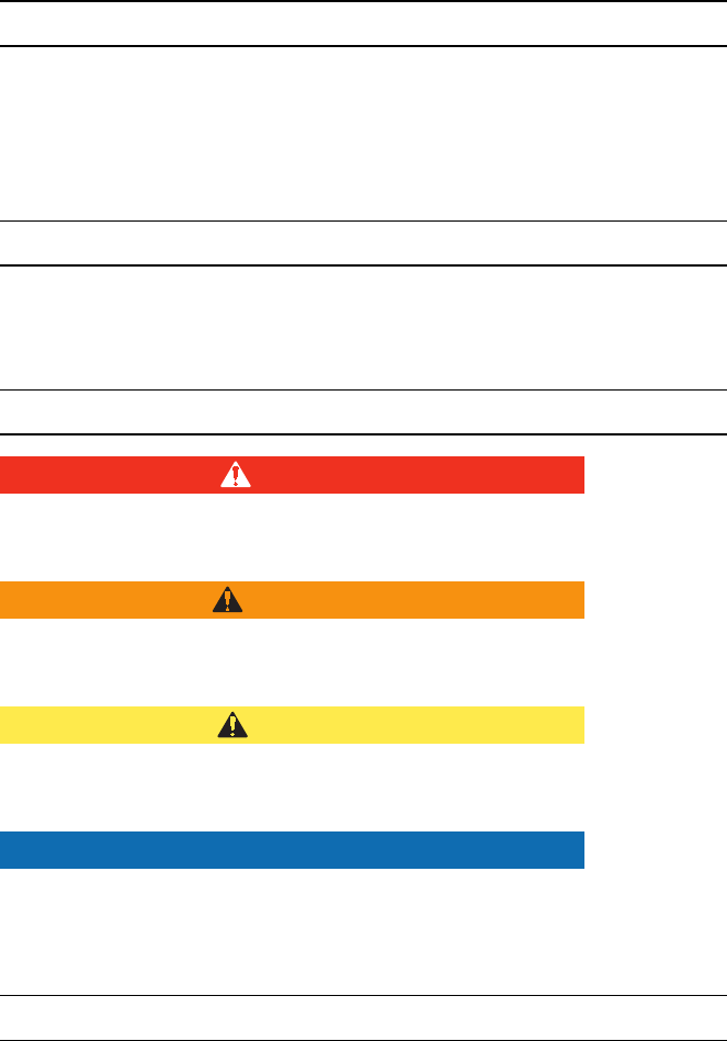
DANGER
indicates an imminently hazardous situation which, if not avoided,
will result in death or serious injury.
WARNING
indicates a potentially hazardous situation which, if not avoided,
could result in death or serious injury.
CAUTION
indicates a potentially hazardous situation which, if not avoided, may
result in minor or moderate injury.
NOTICE
indicates a potentially hazardous situation which, if not avoided, may
result in property damage.
Meaning of the note
"Note:"
Refers a) to manufacturer's information that relates directly or indirectly to the safety
of people or protection of property. The information does not relate directly to a risk
or dangerous situation.
Refers b) to manufacturer's information that is important or useful for operating or
servicing the unit.
Dok.-Nr: D110127-EN, Ver.: 000, ÄM-Nr: 16446, Gültig ab: 10.05.16, Gedruckt: MZECEVIC/02.06.16, Ausdruck nicht maßstäblich und kein Original.Dok.-Nr: D110127-EN, Ver.: 000, ÄM-Nr: 16446, Gültig ab: 10.05.16, Gedruckt: MZECEVIC/02.06.16, Ausdruck nicht maßstäblich und kein Original.

1 • Safety Instructions
10 / 158
80114-601
03.16
Who must read this User Manual?
Knowledge of the User Manual is absolutely essential for correct operation of the unit.
The User Manual must therefore be read by everyone who works with the equipment.
Anyone who prepares, sets, disassembles, cleans and disinfects the unit must also
read the User Manual.
Please pay particular attention to the safety instructions in each chapter.
Compliance with safety information
Working with medical equipment is associated with certain risks to patients, medical
personnel and the environment. Risks cannot be entirely eliminated by design mea-
sures alone.
Safety does not depend solely on the equipment. Safety depends to a large extent on
the training of medical personnel and correct operation of the equipment.
The safety instructions in this chapter must be read, understood and applied by every-
one who is working with the equipment.
Structure of safety instructions
The safety instructions are structured according to the following risks:
•Operating errors and incorrect installation by persons without training
•Risks due to the environment
•Electric shock
•Fire / explosion
•Burns
•Risks due to incorrect use of the return electrode
•Defective unit
•Interference caused by the unit
•Damage to the unit and accessories
•Notes
Dok.-Nr: D110127-EN, Ver.: 000, ÄM-Nr: 16446, Gültig ab: 10.05.16, Gedruckt: MZECEVIC/02.06.16, Ausdruck nicht maßstäblich und kein Original.Dok.-Nr: D110127-EN, Ver.: 000, ÄM-Nr: 16446, Gültig ab: 10.05.16, Gedruckt: MZECEVIC/02.06.16, Ausdruck nicht maßstäblich und kein Original.
11 / 158
1 • Safety Instructions
80114-601
03.16
Operating errors and incorrect installation by persons without training
WARNING
Operating errors and incorrect installation by persons without
training
Persons without training can operate or install the unit incorrectly.
Risk of injury or death for patients and medical staff! Risk of damage
to property.
The equipment may only be used and installed by persons who
have been trained on how to use and install it properly according
to this User Manual.
Training may only be carried out by persons who are suitable on
the basis of their knowledge and practical experience.
In the event of uncertainties or if you have any questions, please
contact Erbe Elektromedizin. You will find the addresses in the ad-
dress list at the end of this User Manual.
Risks due to the environment
NOTICE
Interference with the unit by portable and mobile HF communica-
tion devices (e.g. mobile phones, WLAN equipment)
Electromagnetic waves emitted by portable and mobile HF commu-
nication devices can effect the unit.
The unit may fail or not perform properly.
Please see the table "Recommended separation distances be-
tween portable and mobile HF communications equipment and
the equipment" at the end of this User Manual.
NOTICE
Unsuitable temperature or level of humidity during operation
If you operate the equipment at an unsuitable temperature or level
of humidity, it may sustain damage, fail, or not perform properly.
Operate the equipment at a suitable temperature and level of hu-
midity. You will find the tolerances for temperature and humidity
in the Technical Data.
If other ambient conditions must be observed for operation of the
equipment, you will also find them in the Technical Data.
NOTICE
Unsuitable temperature or humidity in transit or storage
If you transport or store the equipment at an unsuitable temperature
or level of humidity, it may sustain damage and fail.
Transport and store the equipment at a suitable temperature and
level of humidity. You will find the tolerances for temperature and
humidity in the Technical Data.
If other ambient conditions must be observed for transport and
storage of the equipment, you will also find them in the Technical
Data.
Dok.-Nr: D110127-EN, Ver.: 000, ÄM-Nr: 16446, Gültig ab: 10.05.16, Gedruckt: MZECEVIC/02.06.16, Ausdruck nicht maßstäblich und kein Original.Dok.-Nr: D110127-EN, Ver.: 000, ÄM-Nr: 16446, Gültig ab: 10.05.16, Gedruckt: MZECEVIC/02.06.16, Ausdruck nicht maßstäblich und kein Original.
1 • Safety Instructions
12 / 158
80114-601
03.16
NOTICE
Insufficient acclimatization time, unsuitable temperature during
acclimatization
If the device was stored or transported below or above a certain tem-
perature, it will take a certain time and temperature to acclimatize.
If you do not observe the rules, the device can sustain damage and
fail.
Acclimatize the device according to the rules in the Technical Data.
NOTICE
Overheating of the device due to poor ventilation
If ventilation is poor, the device can overheat, sustain damage, and
fail.
Install the device in such a way that there is an unobstructed cir-
culation of air around the housing. Installation in confined wall re-
cesses is prohibited.
NOTICE
Penetration of liquid into the device
The housing is not absolutely watertight. If liquid penetrates, the de-
vice can sustain damage and fail.
Make sure no liquid can penetrate the device.
Do not place vessels containing liquids on top of the device.
Electric shock
WARNING
Defective grounded power outlet, power supply network without
proper grounding, inferior-quality power cord, incorrect line volt-
age, multiple power outlets, extension cords
Risk of electric shock and other injuries to the patient and medical
personnel! Risk of damage to property.
Connect the unit / the equipment cart to a properly installed
grounded power outlet.
Only connect the unit to a power supply network with proper
grounding.
Only use the Erbe power cord or an equivalent power cord for this
purpose. The power cord must bear the applicable national test
symbol.
Check the power cord for damage. You must not use a damaged
power cord.
The supply voltage must match the voltage specified on the unit's
rating plate.
Do not use multiple power outlets.
Do not use extension cords.
Dok.-Nr: D110127-EN, Ver.: 000, ÄM-Nr: 16446, Gültig ab: 10.05.16, Gedruckt: MZECEVIC/02.06.16, Ausdruck nicht maßstäblich und kein Original.Dok.-Nr: D110127-EN, Ver.: 000, ÄM-Nr: 16446, Gültig ab: 10.05.16, Gedruckt: MZECEVIC/02.06.16, Ausdruck nicht maßstäblich und kein Original.
13 / 158
1 • Safety Instructions
80114-601
03.16
WARNING
Incorrect line fuse, defective device
Risk of electric shock to the patient and medical personnel! Risk of
damage to property.
Blown line fuses may only be replaced by a competent technician.
Only replacement fuses that have the same rating as the one
specified on the unit’s rating plate may be used.
When a fuse has been changed, the function of the unit must be
verified. If the unit does not function properly or if there are any
concerns, please contact Erbe.
WARNING
Connection of unit / equipment cart and power supply during
cleaning and disinfection
Risk of electric shock to the medical personnel!
Switch off the device. Unplug the power cord of the device/equip-
ment cart.
Fire / explosion
In electrosurgery electric sparks and arcs occur at the instrument. Flammable gases,
vapors, and liquids can be set alight or caused to explode.
DANGER
Flammable anesthetics
Risk of explosion to the patient and medical personnel! Risk of dam-
age to property.
Do not use flammable anesthetics when an operation is being
performed on the head or thorax.
If use is unavoidable, you must extract the anesthetics before per-
forming electrosurgery.
WARNING
Flammable gas mixture in TUR (Transurethral Resection) and TCR
(Transcervical Endometrial Resection)
Hydrogen and oxygen can ascend into the roof of the bladder, the
upper part of the prostate, and the upper part of the uterus. If you
resect into this gas mixture, it could combust.
Risk of combustion to the patient!
Allow the gas mixture to escape through the resectoscope sheath.
Do not resect into the gas mixture.
DANGER
Flammable endogenous gases in the gastrointestinal tract
Risk of explosion to the patient!
Extract the gases before performing electrosurgery or irrigate
with CO2.
Dok.-Nr: D110127-EN, Ver.: 000, ÄM-Nr: 16446, Gültig ab: 10.05.16, Gedruckt: MZECEVIC/02.06.16, Ausdruck nicht maßstäblich und kein Original.Dok.-Nr: D110127-EN, Ver.: 000, ÄM-Nr: 16446, Gültig ab: 10.05.16, Gedruckt: MZECEVIC/02.06.16, Ausdruck nicht maßstäblich und kein Original.
1 • Safety Instructions
14 / 158
80114-601
03.16
DANGER
Combustion-supporting gases, e.g. oxygen, nitrous oxide
The gases can accumulate in materials like cotton wool or gauze. The
materials become highly flammable.
Risk of fire to the patient and medical personnel! Risk of damage to
property.
Do not use combustion-supporting gases when an operation is
being performed on the head or thorax.
If use is unavoidable, you must extract the combustion-support-
ing gases before performing electrosurgery.
Remove any jeopardized (e.g. cotton wool or gauze) materials be-
fore performing electrosurgery.
Check the oxygen-carrying tubes and connections for leaks.
Check the endotracheal tubes and their cuffs for leaks.
Before using argon plasma coagulation (APC) in the tracheobron-
chial system it is absolutely essential that you observe the specific
safety information and instructions in the User Manual for the ar-
gon plasma unit!
WARNING
Active or hot instruments in contact with combustible materials
Materials like gauze, swabs, and cloths can catch fire.
Risk of fire to the patient and medical personnel! Risk of damage to
property.
Do not bring active or hot instruments into contact with combus-
tible materials.
Put instruments down in a safe place: sterile, dry, non-conductive,
and easy to see. Instruments that have been put down must not
come into contact with the patient, medical personnel, or com-
bustible materials.
WARNING
Flammable detergents and disinfectants, flammable solvents in
adhesives used on the patient and on the device / equipment cart
Risk of fire and explosion to the patient and medical personnel! Risk
of damage to property.
Use products that are not flammable.
If the use of flammable products is unavoidable, proceed as fol-
lows:
Allow the products to evaporate completely before switching on
the device.
Check whether flammable liquids have accumulated under the
patient, in body recesses such as the navel, or in body cavities
such as the vagina. Remove any liquids before performing elec-
trosurgery.
Dok.-Nr: D110127-EN, Ver.: 000, ÄM-Nr: 16446, Gültig ab: 10.05.16, Gedruckt: MZECEVIC/02.06.16, Ausdruck nicht maßstäblich und kein Original.Dok.-Nr: D110127-EN, Ver.: 000, ÄM-Nr: 16446, Gültig ab: 10.05.16, Gedruckt: MZECEVIC/02.06.16, Ausdruck nicht maßstäblich und kein Original.
15 / 158
1 • Safety Instructions
80114-601
03.16
WARNING
Ignition of anesthetics, skin cleansers, and disinfectants in poten-
tially explosive atmospheres
If you place the device in a potentially explosive atmosphere, anes-
thetics, skin cleansers, and disinfectants can ignite.
Risk of fire and explosion to the patient and medical personnel! Risk
of damage to property.
Do not place the device in potentially explosive atmospheres.
Burns
WARNING
Damaged device, damaged accessories, modified device, and
modified accessories
Risk of burns and injury to the patient and medical personnel! Risk
of damage to property.
Check the device and accessories for damage every time before
using them (e.g. footswitch, cords of instruments and the return
electrode, equipment cart).
You must not use damaged equipment or damaged accessories.
Replace defective accessories.
If the equipment or equipment cart is damaged, please contact
our customer service.
For your safety and that of the patient: Never attempt to perform
repairs or make modifications yourself. Any modification will in-
validate liability on the part of Erbe Elektromedizin GmbH.
WARNING
HF leakage current flows through metal parts
The patient must not have contact with electrically conductive ob-
jects. That includes metal parts of the operating table, for example.
HF current can be discharged through points of contact accidentally
(HF leakage current).
Risk of burns to the patient!
Position the patient on dry, antistatic drapes.
If the drapes can become wet during the operation due to sweat,
blood, irrigation liquid, urine, etc., lay a waterproof plastic sheet
under the drapes.
WARNING
HF leakage current flows through monitoring electrodes
HF current can be discharged through points of contact between the
skin and monitoring electrodes accidentally (HF leakage current).
Risk of burns to the patient!
Position monitoring electrodes as far away as possible from the
surgical field (area where electrosurgical instruments are used).
Do not use needle electrodes for monitoring during electrosurgery.
Where possible, use monitoring electrodes that contain devices to
limit high-frequency current.
Dok.-Nr: D110127-EN, Ver.: 000, ÄM-Nr: 16446, Gültig ab: 10.05.16, Gedruckt: MZECEVIC/02.06.16, Ausdruck nicht maßstäblich und kein Original.Dok.-Nr: D110127-EN, Ver.: 000, ÄM-Nr: 16446, Gültig ab: 10.05.16, Gedruckt: MZECEVIC/02.06.16, Ausdruck nicht maßstäblich und kein Original.
1 • Safety Instructions
16 / 158
80114-601
03.16
WARNING
HF leakage current flows through skin-to-skin points of contact
HF current can be discharged through skin-to-skin points of contact
accidentally (HF leakage current).
Risk of burns to the patient!
Prevent skin-to-skin points of contact. For example, lay dry gauze
between the patient's arms and body.
WARNING
Unintentional activation of the instrument
Risk of burns to the patient and medical personnel!
Put instruments down in a safe place: sterile, dry, non-conductive,
and easy to see. Instruments that have been put down must not
come into contact with the patient, medical personnel, or com-
bustible materials.
Instruments that have been put down must not come into contact
with the patient, not even indirectly. An instrument can come into
contact with the patient indirectly through electrically conductive
objects or wet drapes, for example.
CAUTION
Hot instruments
Even non-active instruments that are still hot can burn the patient or
medical personnel.
Put instruments down in a safe place: sterile, dry, non-conductive,
and easy to see. Instruments that have been put down must not
come into contact with the patient, medical personnel, or com-
bustible materials.
Instruments that have been put down must not come into contact
with the patient, not even indirectly. An instrument can come into
contact with the patient indirectly through electrically conductive
objects or wet drapes, for example.
WARNING
Unintentional activation of the instrument during an endoscopic
application
If the instrument is activated and remains activated during an endo-
scopic application, the patient can suffer burns when the instrument
is removed.
All points that come into contact with the active part of the instru-
ment are at risk. The cause of unintentional activation can be a fault
in the footswitch or device for example.
You will recognize unintentional activation from the continuous acti-
vation signal, even though you have released the footswitch.
Risk of burns to the patient!
Turn off the power switch on the electrosurgical unit immediately.
Only then should the instrument be removed from the patient’s
body.
Dok.-Nr: D110127-EN, Ver.: 000, ÄM-Nr: 16446, Gültig ab: 10.05.16, Gedruckt: MZECEVIC/02.06.16, Ausdruck nicht maßstäblich und kein Original.Dok.-Nr: D110127-EN, Ver.: 000, ÄM-Nr: 16446, Gültig ab: 10.05.16, Gedruckt: MZECEVIC/02.06.16, Ausdruck nicht maßstäblich und kein Original.
17 / 158
1 • Safety Instructions
80114-601
03.16
WARNING
Capacitive coupling between the cords of two instruments
When one instrument is activated, current can be transferred to the
cord of another instrument (capacitive coupling).
The patient can suffer burns if the non-active but still live instrument
has direct or indirect contact with the patient.
Risk of burns to the patient!
Lay the cords of instruments in such a way that they are as far
apart as possible.
Put instruments down in a safe place: sterile, dry, non-conductive,
and easy to see.
Instruments that have been put down must not come into contact
with the patient, medical personnel, or combustible materials.
Instruments that have been put down must not come into contact
with the patient, not even indirectly. An instrument can come into
contact with the patient indirectly through electrically conductive
objects or wet drapes, for example.
WARNING
Activation time too long, effects too high
The longer the activation time of the unit and the higher the effect,
the higher the risk of accidental tissue damage.
Risk of accidental tissue damage to the patient!
Activate the unit for as short a time as possible relative to the re-
quired surgical effect.
The temperature at the return electrode site increases during long
and continuous activations; therefore, ensure that the cooling
phases between activations are sufficient.
Set the effect as low as possible relative to the required surgical
effect. However, an effect level that is too low can be dangerous,
e.g. gas embolisms in connection with the APC (Argon Plasma Co-
agulation), because the plasma does not ignite at an effect level
that is too low.
If you are unable to achieve a surgical effect with an activation
time / effect level that is normally sufficient judging from experi-
ence, this can be due to a problem with the electrosurgical unit or
accessories:
Check the instrument for soiling with insulating tissue remnants.
Check the return electrode to make sure it is secure.
Check the connectors on all cords to make sure they are secure.
WARNING
Activation of the unit with no knowledge of active settings
If the user does not understand the active settings of the unit, he can
cause the patient accidental tissue damage.
Check the active settings on the display of the unit, after: switch-
ing on the unit, connecting up an instrument, and changing the
program.
Dok.-Nr: D110127-EN, Ver.: 000, ÄM-Nr: 16446, Gültig ab: 10.05.16, Gedruckt: MZECEVIC/02.06.16, Ausdruck nicht maßstäblich und kein Original.Dok.-Nr: D110127-EN, Ver.: 000, ÄM-Nr: 16446, Gültig ab: 10.05.16, Gedruckt: MZECEVIC/02.06.16, Ausdruck nicht maßstäblich und kein Original.
1 • Safety Instructions
18 / 158
80114-601
03.16
WARNING
The user was not informed of a change in maximum activation
time
Risk of accidental tissue damage to the patient!
All users must be informed in good time of any change in maxi-
mum activation time. That is, before the user works with the mod-
ified maximum activation time for the first time.
The temperature at the return electrode site increases during long
and continuous activations; therefore, ensure that the cooling
phases between activations are sufficient.
WARNING
Tissue structures / vessels with a cross-section that is small or
becoming smaller
If monopolar HF current flows through parts of the body with a rela-
tively small cross-section, there is a risk of unintentional coagulation
for the patient!
If possible, use the bipolar coagulation technique.
WARNING
Activation signal not audible
You do not hear the signal when the electrosurgical unit is activated.
Risk of burns to the patient and medical personnel!
Adjust the activation signal so that it is clearly audible.
WARNING
Undesirable contact between the active instrument and metal
objects in the patient's body
Contact with metal hemostats, etc.
Risk of burns to the patient!
Do not touch metal objects (e.g. implants) in the patient's body
with the active instrument.
CAUTION
A hand-held metal instrument is touched with the active instru-
ment (electrode)
Risk of hand burns!
Such practice is not recommended. The risk of burns cannot be
ruled out.
Dok.-Nr: D110127-EN, Ver.: 000, ÄM-Nr: 16446, Gültig ab: 10.05.16, Gedruckt: MZECEVIC/02.06.16, Ausdruck nicht maßstäblich und kein Original.Dok.-Nr: D110127-EN, Ver.: 000, ÄM-Nr: 16446, Gültig ab: 10.05.16, Gedruckt: MZECEVIC/02.06.16, Ausdruck nicht maßstäblich und kein Original.
19 / 158
1 • Safety Instructions
80114-601
03.16
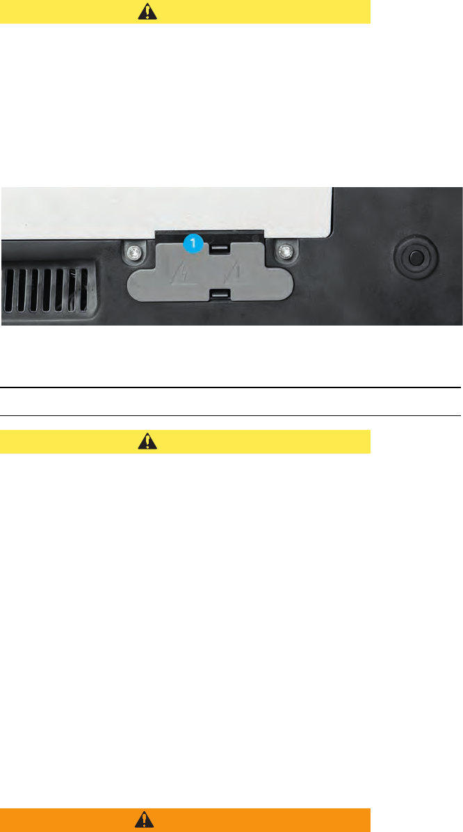
CAUTION
The interconnections of the VIO 3 carry HF voltage when they are
activated.
If you touch the interconnections during activation, you can suffer
burns.
You may only remove the cap (1) (fig. below) if you install the VIO
3 on an APC 3.
Keep the cap in a safe place. If you disconnect the VIO 3 from the
APC 3, you must replace the cap on the interconnections.
Fig. 1-1
Risks due to incorrect use of the return electrode
CAUTION
Non-compatible or non-split return electrode
When applying a non-compatible return electrode, it should be ex-
pected that monitoring the contact between return electrode and
skin is faulty.
When applying a non-split return electrode, the contact between re-
turn electrode and skin is not monitored. If contact between return
electrode and skin is inadequate, the unit does not emit any visual or
acoustic warning signal.
Risk of burns for the patient under the return electrode!
Check in the accompanying papers of the manufacturer whether
the return electrode is suitable for the VIO device used.
Use only suitable return electrodes.
When applying a non-split return electrode: Regularly check the
return electrode for good skin contact.
Check in the accompanying papers of the manufacturer whether
the return electrode cable is suitable for the return electrode
used.
Use only suitable return electrode cables.
WARNING
Positioning the return electrode above the heart
Risk of ventricular fibrillation and cardiac arrest for the patient!
Do not position the return electrode over the heart or in the region
of the heart.
Dok.-Nr: D110127-EN, Ver.: 000, ÄM-Nr: 16446, Gültig ab: 10.05.16, Gedruckt: MZECEVIC/02.06.16, Ausdruck nicht maßstäblich und kein Original.Dok.-Nr: D110127-EN, Ver.: 000, ÄM-Nr: 16446, Gültig ab: 10.05.16, Gedruckt: MZECEVIC/02.06.16, Ausdruck nicht maßstäblich und kein Original.
1 • Safety Instructions
20 / 158
80114-601
03.16
CAUTION
Incorrect application of the neutral electrode
Risk of burns to the patient!
Apply the entire contact surface of the neutral electrode to a mus-
cular part of the body with good blood circulation.
Apply the neutral electrode as close as possible to the surgical
site.
Insert the contact tab of the neutral electrode completely into the
connecting clamp. The contact tab must not touch the patient's
skin.
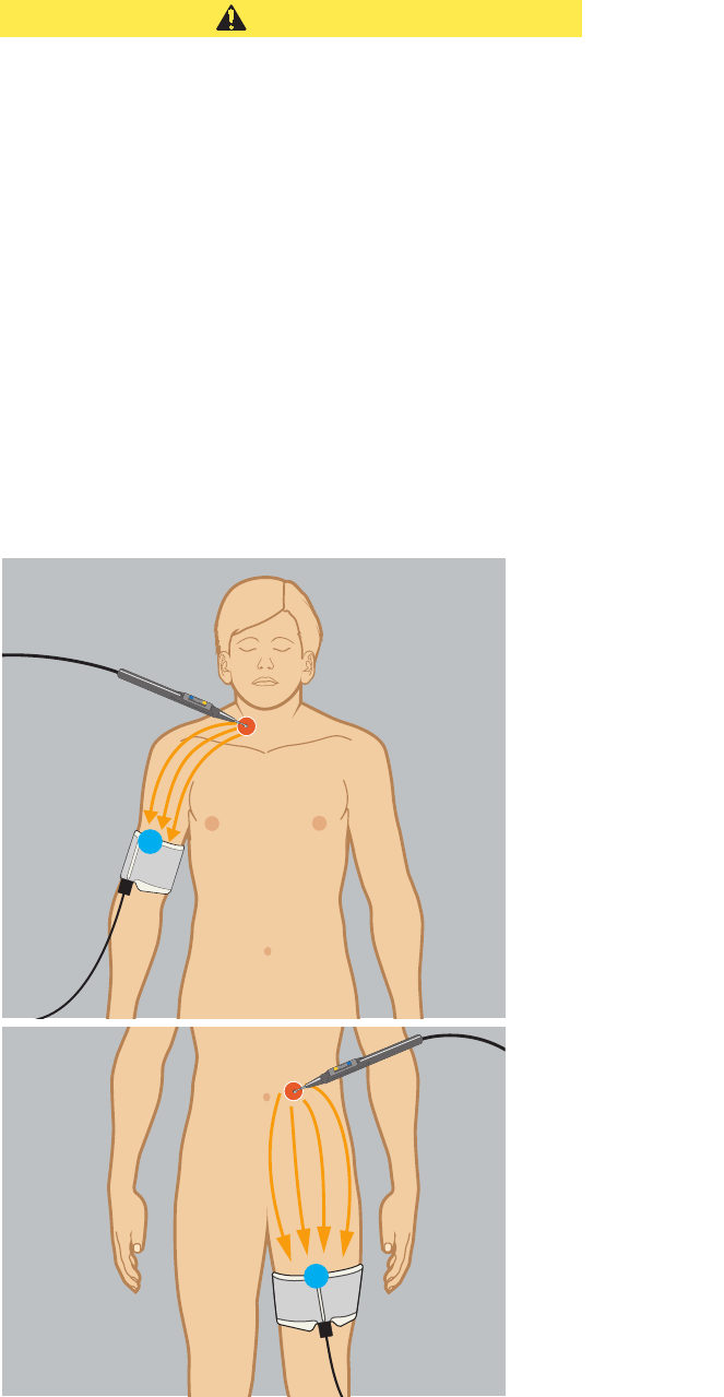
Align the long edge of the return electrode (1) towards the surgi-
cal field. The current should flow from the instrument towards the
long edge of the return electrode. See Fig. 1-2.
Check the neutral electrode regularly for good contact with the
patient's skin.
Check the neutral electrode especially when the patient has been
repositioned and after surgical steps where the device was acti-
vated frequently and for a long time.
Fig. 1-2
1
1
Dok.-Nr: D110127-EN, Ver.: 000, ÄM-Nr: 16446, Gültig ab: 10.05.16, Gedruckt: MZECEVIC/02.06.16, Ausdruck nicht maßstäblich und kein Original.Dok.-Nr: D110127-EN, Ver.: 000, ÄM-Nr: 16446, Gültig ab: 10.05.16, Gedruckt: MZECEVIC/02.06.16, Ausdruck nicht maßstäblich und kein Original.
21 / 158
1 • Safety Instructions
80114-601
03.16
Defective unit
WARNING
Undesirable rise in output level due to failure of electrosurgical
unit
Risk of accidental tissue damage to the patient!
The device shuts off independently.
To guard against a possible failure of the electrosurgical unit,
have the device checked for safety at least once a year.
WARNING
Technical safety checks not being done
Risk of injury or death for patients and medical staff! Risk of damage
to property.
Have the device checked for safety at least once a year.
You must not use a device that is not safe.
WARNING
Failure of display elements
If display elements fail, you can no longer operate the device safely.
Risk of injury or death for patients and medical staff!
You must not use the unit.
Interference caused by the unit
WARNING
Interference with cardiac pacemakers, internal defibrillators, or
other active implants
Activation of the electrosurgical unit may affect the performance of
active implants or damage them.
Risk of injury or death for patients!
In the case of patients having active implants, consult the manu-
facturer of the implant or the competent department of your hos-
pital prior to performing surgery.
Do not position the return electrode near cardiac pacemakers, in-
ternal defibrillators, or other active implants.
NOTICE
Interference with electronic equipment due to the electrosurgical
unit
The activated electrosurgical unit can affect the performance of elec-
tronic equipment by causing interference.
The equipment may fail or not perform properly.
Position the electrosurgical unit, the cords of the instruments, and
the cord of the return electrode as far away as possible from elec-
tronic equipment.
Position the cords as far away as possible from the cords of elec-
tronic equipment.
Dok.-Nr: D110127-EN, Ver.: 000, ÄM-Nr: 16446, Gültig ab: 10.05.16, Gedruckt: MZECEVIC/02.06.16, Ausdruck nicht maßstäblich und kein Original.Dok.-Nr: D110127-EN, Ver.: 000, ÄM-Nr: 16446, Gültig ab: 10.05.16, Gedruckt: MZECEVIC/02.06.16, Ausdruck nicht maßstäblich und kein Original.
1 • Safety Instructions
22 / 158
80114-601
03.16
WARNING
Low-frequency currents stimulate nerves and muscles (Neuro-
muscular Stimulation)
Low-frequency currents arise either due to low-frequency power
sources or partial rectification of the HF current. Spasms or muscle
contractions can occur.
Risk of injury to the patient.
Set effect as low as possible relative to the required surgical ef-
fect.
NOTICE
Use of non-approved internal cables by Technical Service
This can result in the increased emission of electromagnetic waves or
reduce the immunity of the device.
The unit may fail or not perform properly.
Technical Service may only use the internal cables that are listed
in the service manual for the device.
NOTICE
Stacked devices
If you stack the device next to other equipment or with other equip-
ment, the devices can affect each other.
The unit may fail or not perform properly.
The device may only be stacked next to or with VIO series units.
If it is necessary to operate the device near other equipment or
stacked together with other equipment, check whether the devic-
es are affecting each other: Are the devices behaving unusually?
Do errors occur?
Damage to the unit and accessories
NOTICE
Alcohol-based spray disinfectant for fast disinfection
In the case of elastic molded parts and paint surfaces, there is a risk
of formation of cracks. Propanol and ethanol will attack the surfaces.
Do not use these substances.
NOTICE
Alternate use of disinfectant solutions based on different active
ingredients
A color reaction may occur with plastics.
Do not use these substances alternately.
Dok.-Nr: D110127-EN, Ver.: 000, ÄM-Nr: 16446, Gültig ab: 10.05.16, Gedruckt: MZECEVIC/02.06.16, Ausdruck nicht maßstäblich und kein Original.Dok.-Nr: D110127-EN, Ver.: 000, ÄM-Nr: 16446, Gültig ab: 10.05.16, Gedruckt: MZECEVIC/02.06.16, Ausdruck nicht maßstäblich und kein Original.
23 / 158
1 • Safety Instructions
80114-601
03.16
CAUTION
Electric load on instrument too high
The instrument can be damaged.
If the damaged area comes into contact with tissue, it can lead to un-
intentional coagulation.
Determine the electrical capacity of the instrument. It is either
printed on the instrument or can be found in the user manual.
Compare the electrical capacity of the instrument with the maxi-
mum HF peak voltage of the required mode.
Instructions are available in the "Accessories" chapter.
CAUTION
Very long activation cycles without cooling phases
The electrosurgical unit is designed and tested for a relative activa-
tion time of 25% (in accordance with IEC 60601-2-2). If you under-
take long activation phases without the appropriate cooling breaks,
gradual heating under the return electrode may occur, or the unit
may sustain damage.
Risk of burns to the patient!
Keep to a 25% relative activation time (see also Technical Data,
Operating Mode) if you operate the unit over a prolonged period.
Notes
Grounding Note: If necessary, the equipment can be connected to the external grounding system
of the room with the grounding pin on the back of the unit and/or Cart using a con-
necting cable designed for this purpose. Affects of low frequency leakage currents due
to a defective grounding system within the room may be eliminated through external
grounding.
Use of a defibrillator Note: All HF receptacles and the return electrode receptacle (applied parts) meet Type
CF requirements and are protected against the effects of defibrillator discharge.
Using a smoke evacuator Note: In order to evacuate the smoke that develops during electrosurgical procedures,
Erbe recommends using a smoke evacuator.
Dok.-Nr: D110127-EN, Ver.: 000, ÄM-Nr: 16446, Gültig ab: 10.05.16, Gedruckt: MZECEVIC/02.06.16, Ausdruck nicht maßstäblich und kein Original.Dok.-Nr: D110127-EN, Ver.: 000, ÄM-Nr: 16446, Gültig ab: 10.05.16, Gedruckt: MZECEVIC/02.06.16, Ausdruck nicht maßstäblich und kein Original.
1 • Safety Instructions
24 / 158
80114-601
03.16
Dok.-Nr: D110127-EN, Ver.: 000, ÄM-Nr: 16446, Gültig ab: 10.05.16, Gedruckt: MZECEVIC/02.06.16, Ausdruck nicht maßstäblich und kein Original.Dok.-Nr: D110127-EN, Ver.: 000, ÄM-Nr: 16446, Gültig ab: 10.05.16, Gedruckt: MZECEVIC/02.06.16, Ausdruck nicht maßstäblich und kein Original.

25 / 158
2 • Safety Features
80114-601
03.16
Chapter 2
Safety Features
NESSY
What is NESSY? Should you wish to activate the unit’s monopolar mode, you have to connect a return
electrode and apply it on the patient.
The unit is equipped with a Neutral Electrode Safety System (NESSY), which monitors
the return electrode, warns of critical situations, and thus prevents burns. Observe the
unit’s optical and acoustic warning signals. Observe the error and advisory messages
from return electrode monitoring.
Safety when connecting a split or
non-split return electrode
You can connect a split or a non-split return electrode to the VIO 3. Erbe recommends
connecting a split return electrode, as it offers enhanced safety with regard to burns.
When connecting a split return electrode, three safety-relevant properties are moni-
tored:
•the connection to the VIO 3
•the contact to the patient’s skin
•the application direction of the return electrode (NESSY symmetry monitoring)
When connecting a non-split return electrode, only one safety-relevant property is
monitored:
•the connection to the VIO 3
Preferred return electrode type In the VIO 3 Protected settings, you or an authorized person can set whether you wish
to work with a split or non-split return electrode.
If you connect the preferred type of return electrode, you do not need to register the
return electrode on the VIO 3.
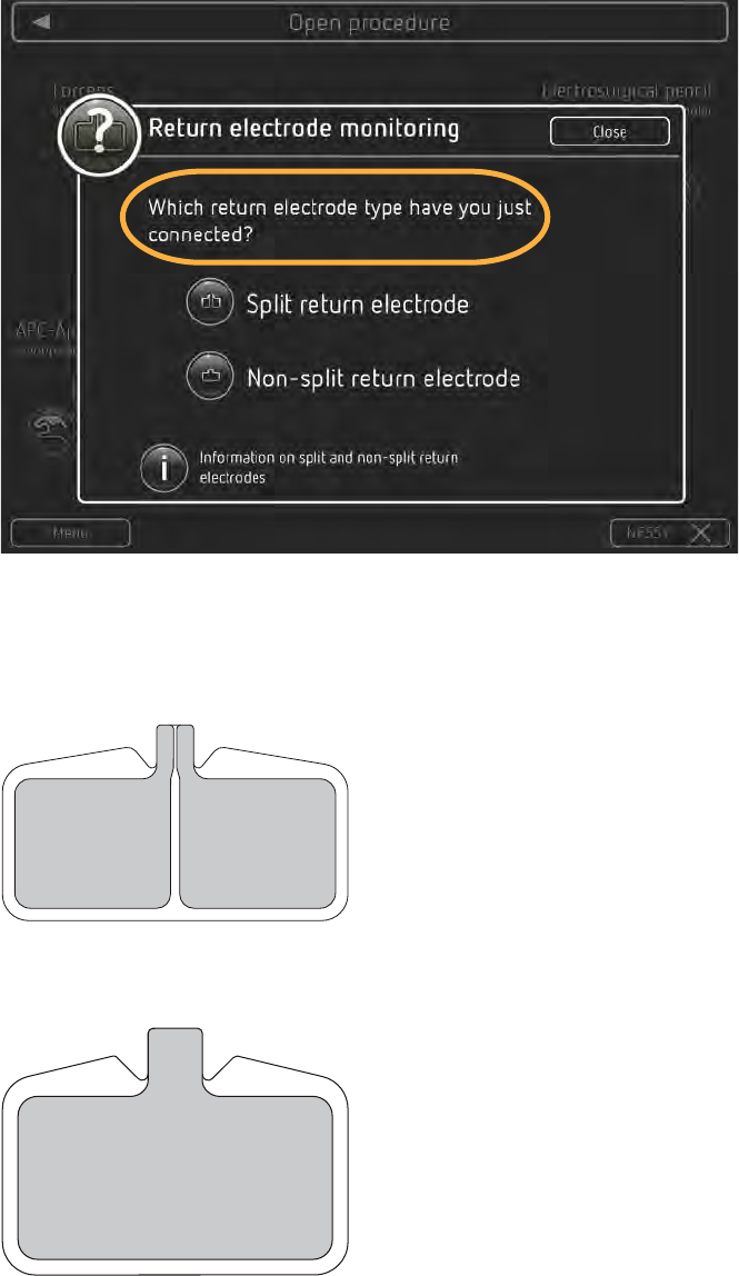
If you connect another type of return electrode, VIO 3 asks you: Which return electrode
type have you just connected? You then have to make the decision between a split or
a non-split return electrode.
Dok.-Nr: D110127-EN, Ver.: 000, ÄM-Nr: 16446, Gültig ab: 10.05.16, Gedruckt: MZECEVIC/02.06.16, Ausdruck nicht maßstäblich und kein Original.Dok.-Nr: D110127-EN, Ver.: 000, ÄM-Nr: 16446, Gültig ab: 10.05.16, Gedruckt: MZECEVIC/02.06.16, Ausdruck nicht maßstäblich und kein Original.
2 • Safety Features
26 / 158
80114-601
03.16
Fig. 2-1
Note: Make sure you actually register the return electrode on the VIO 3 that you con-
nect. Otherwise, you cannot activate the monopolar modes.
Example: split return electrode:
Fig. 2-2
Example: non-split return electrode:
Fig. 2-3
Dok.-Nr: D110127-EN, Ver.: 000, ÄM-Nr: 16446, Gültig ab: 10.05.16, Gedruckt: MZECEVIC/02.06.16, Ausdruck nicht maßstäblich und kein Original.Dok.-Nr: D110127-EN, Ver.: 000, ÄM-Nr: 16446, Gültig ab: 10.05.16, Gedruckt: MZECEVIC/02.06.16, Ausdruck nicht maßstäblich und kein Original.
27 / 158
2 • Safety Features
80114-601
03.16
VIO 3 detects no return electrode
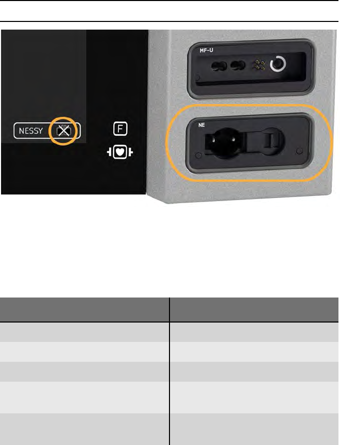
Fig. 2-4
If you switch on the VIO 3 and the unit detects no return electrode, the return electrode
is crossed out on the screen. The frame of the return electrode socket is not lit.
Activation of the monopolar modes is not possible. If you need assistance, touch the
NESSY button.
Possible cause Action
No return electrode connected Connect return electrode
Return electrode not applied to the skin Apply return electrode to the skin
Cable damaged Replace damaged cable
Contact strip is not correctly positioned
in the connecting terminal
Insert the contact strip correctly into
the connecting terminal
Connector is not correctly in the return
electrode socket
Plug connector into the return elec-
trode socket as far as it goes
Dok.-Nr: D110127-EN, Ver.: 000, ÄM-Nr: 16446, Gültig ab: 10.05.16, Gedruckt: MZECEVIC/02.06.16, Ausdruck nicht maßstäblich und kein Original.Dok.-Nr: D110127-EN, Ver.: 000, ÄM-Nr: 16446, Gültig ab: 10.05.16, Gedruckt: MZECEVIC/02.06.16, Ausdruck nicht maßstäblich und kein Original.
2 • Safety Features
28 / 158
80114-601
03.16
Split return electrode connected
Connection correct
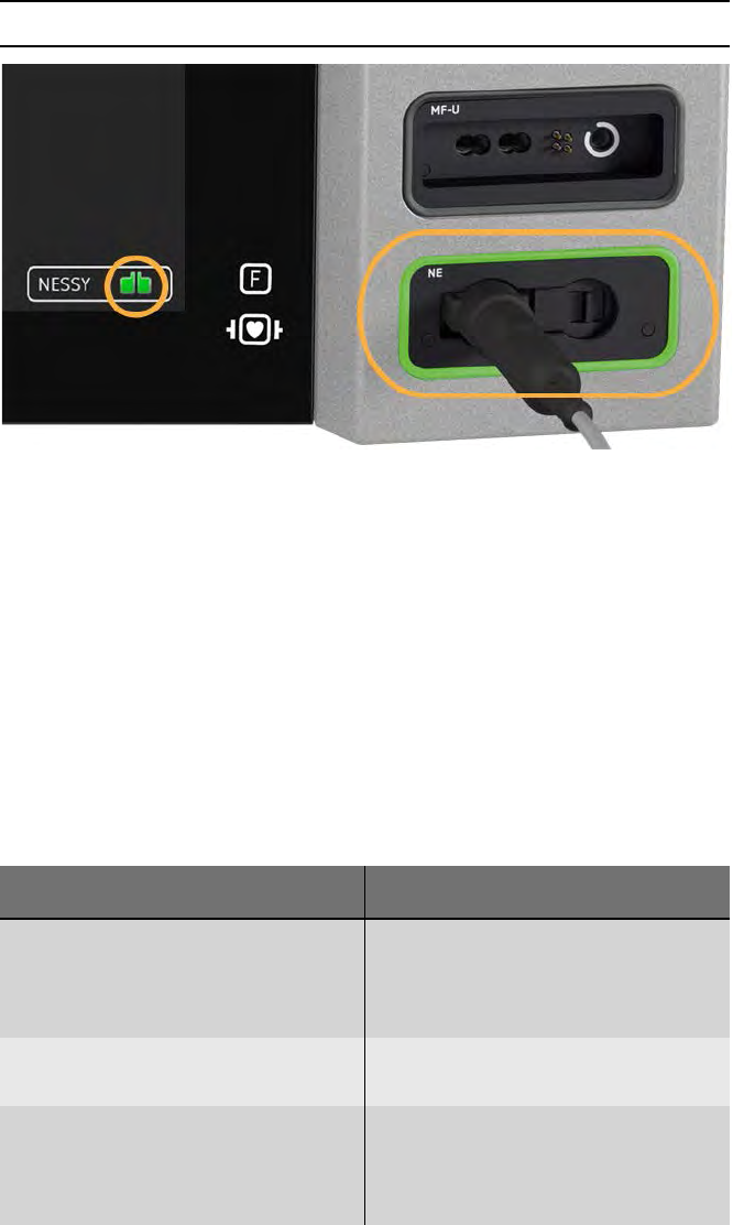
Fig. 2-5
If you connect a split return electrode, the unit monitors:
•the connection to the VIO 3
•the contact to the patient’s skin
•the application direction of the return electrode (NESSY symmetry monitoring)
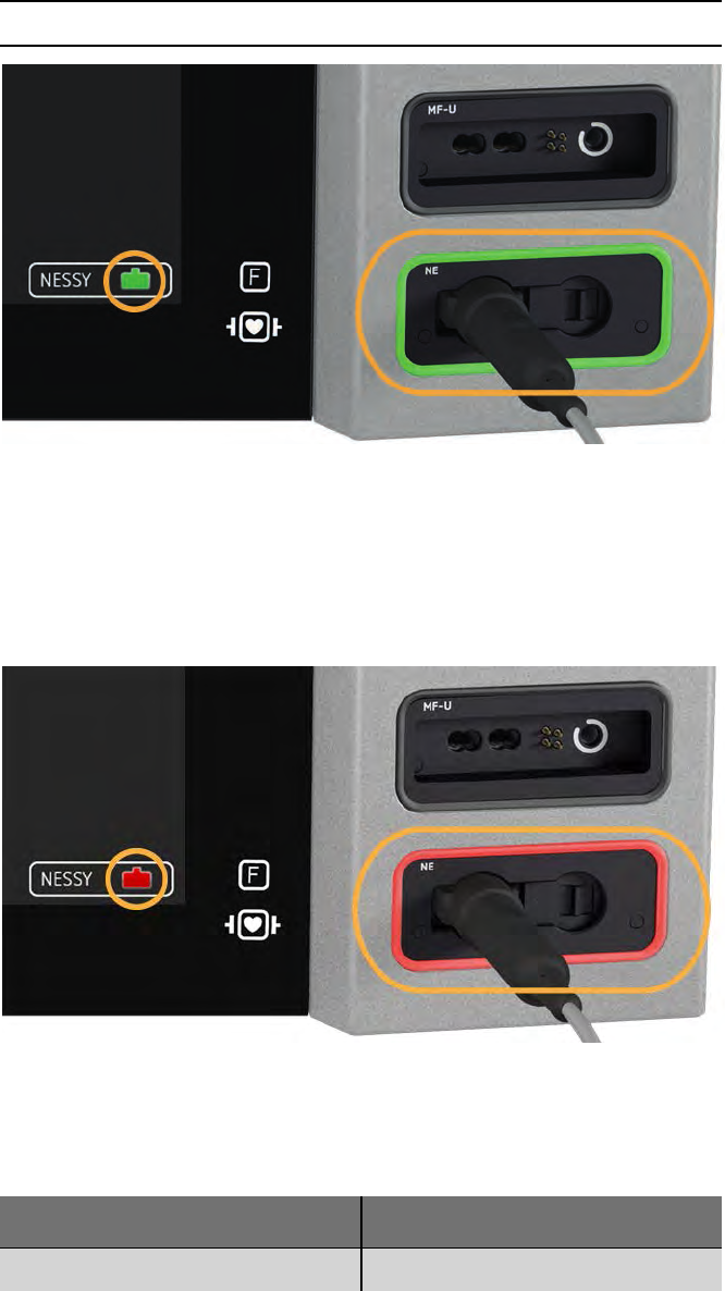
The return electrode on the screen lights green; the frame of the return electrode
socket lights green. The monopolar mode can be activated.
Connection critical, activation still
possible
The return electrode on the screen lights green; the frame of the return electrode
socket lights green. Activation of the monopolar modes is still possible. The return
electrode monitoring alerts you with a reference to a critical situation.
Check the return electrode as soon as possible.
Possible cause Action
Return electrode has too little contact
to the skin
The entire surface of the return elec-
trode must be applied without creases;
the skin must be free of oil, dry and free
from hair.
The long edge of the return electrode
does not point to the surgical field.
Align the long edge of the return elec-
trode towards the surgical field
The return electrode does not support
monitoring of the application direction
of the return electrode (NESSY symme-
try monitoring).
Connect a suitable return electrode
Dok.-Nr: D110127-EN, Ver.: 000, ÄM-Nr: 16446, Gültig ab: 10.05.16, Gedruckt: MZECEVIC/02.06.16, Ausdruck nicht maßstäblich und kein Original.Dok.-Nr: D110127-EN, Ver.: 000, ÄM-Nr: 16446, Gültig ab: 10.05.16, Gedruckt: MZECEVIC/02.06.16, Ausdruck nicht maßstäblich und kein Original.
29 / 158
2 • Safety Features
80114-601
03.16
Connection faulty, activation not
possible
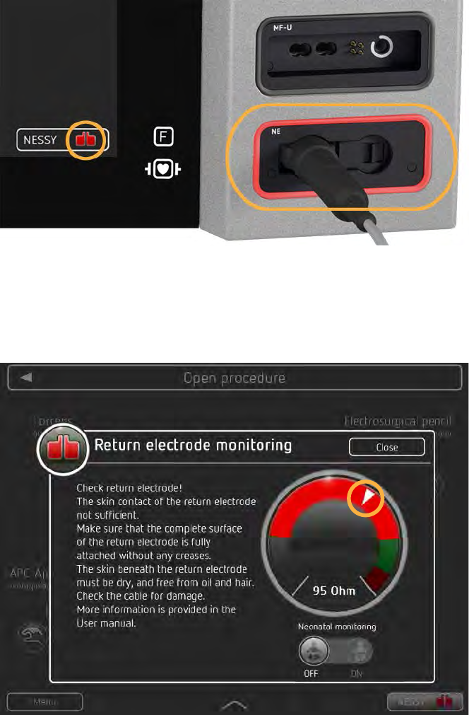
Fig. 2-6
The return electrode on the screen lights red; the frame of the return electrode socket
lights red. Activation of the monopolar modes is not possible. You see a message on
the screen.
Check the return electrode immediately.
Fig. 2-7
An example for a message from return electrode monitoring is given in Fig. 2-7. In ad-
dition to the text, you see on the right a resistance display with resistance ranges. If
the needle is in the gray or red range, you cannot activate monopolar modes.
Dok.-Nr: D110127-EN, Ver.: 000, ÄM-Nr: 16446, Gültig ab: 10.05.16, Gedruckt: MZECEVIC/02.06.16, Ausdruck nicht maßstäblich und kein Original.Dok.-Nr: D110127-EN, Ver.: 000, ÄM-Nr: 16446, Gültig ab: 10.05.16, Gedruckt: MZECEVIC/02.06.16, Ausdruck nicht maßstäblich und kein Original.
2 • Safety Features
30 / 158
80114-601
03.16
Assistance on NESSY symmetry
monitoring
Fig. 2-8
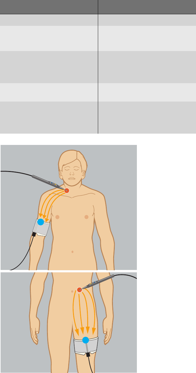
Align the long side of the return electrode (1) towards the surgical field. The cur-
rent should flow from the instrument towards the long edge of the return elec-
trode.
Possible cause Action
Cable damaged Replace damaged cable
Non-split return electrode connected,
but registered on the VIO 3 as a split
return electrode
Connect split return electrode
Return electrode has too little contact
to the skin
The entire surface of the return elec-
trode must be applied without creases;
the skin must be free of oil, dry and free
from hair.
The long edge of the return electrode
does not point to the surgical field.
Align the long edge of the return elec-
trode towards the surgical field
The return electrode does not support
monitoring of the application direction
of the return electrode (NESSY symme-
try monitoring).
Connect a suitable return electrode
1
1
Dok.-Nr: D110127-EN, Ver.: 000, ÄM-Nr: 16446, Gültig ab: 10.05.16, Gedruckt: MZECEVIC/02.06.16, Ausdruck nicht maßstäblich und kein Original.Dok.-Nr: D110127-EN, Ver.: 000, ÄM-Nr: 16446, Gültig ab: 10.05.16, Gedruckt: MZECEVIC/02.06.16, Ausdruck nicht maßstäblich und kein Original.
31 / 158
2 • Safety Features
80114-601
03.16
Non-split return electrode connected
Connection correct
Fig. 2-9
If you connect a non-split return electrode, the unit monitors:
•the connection to the VIO 3
The return electrode on the screen lights green; the frame of the return electrode
socket lights green. The monopolar mode can be activated.
Connection faulty, activation not
possible
Fig. 2-10
The return electrode on the screen lights red; the frame of the return electrode socket
lights red. Activation of the monopolar modes is not possible. You see a message on
the screen.
Note: When applying a non-split return electrode, the contact between the skin and
the return electrode is not monitored! You will not receive a warning if the return elec-
trode becomes detached from the skin and there is a danger of burns. The application
direction of the return electrode is also not monitored. Erbe recommends the use of
split return electrodes.
Possible cause Action
Cable damaged Replace damaged cable
Dok.-Nr: D110127-EN, Ver.: 000, ÄM-Nr: 16446, Gültig ab: 10.05.16, Gedruckt: MZECEVIC/02.06.16, Ausdruck nicht maßstäblich und kein Original.Dok.-Nr: D110127-EN, Ver.: 000, ÄM-Nr: 16446, Gültig ab: 10.05.16, Gedruckt: MZECEVIC/02.06.16, Ausdruck nicht maßstäblich und kein Original.
2 • Safety Features
32 / 158
80114-601
03.16
Neonatal monitoring
Fig. 2-11
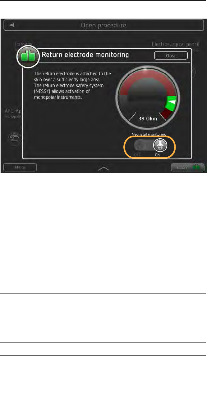
When using a neonatal return electrode, you can activate neonatal monitoring. In crit-
ical situations you then see the following message on the screen:
“An elevated temperature is possible under the return electrode! Activate for as brief
a period as possible. Reduce the effect setting if the situation permits.”
To switch on the neonatal monitoring, proceed as follows:
1. Touch the NESSY button on the main screen.
2. Slide the neonatal monitoring switch to the ON position.
Automatic monitoring of the HF output parameters electrical voltage
and power
The unit is equipped with automatic monitoring of the HF output parameters (voltage
and power). Deviations of the actual value1 from the setpoint2 are monitored. If the
deviation is so great that the quality of the required CUT or COAG effect is no longer
guaranteed, the unit switches off the HF generator and displays a message.
Automatic monitoring of the maximum activation time
With proper use, a HF generator is only briefly activated. A defect in the unit, in the
accessories or a user’s error may cause the HF generator to be activated unintention-
ally. To prevent major damage being caused, the activation time is automatically mon-
itored.
The maximum activation time is saved in the unit’s Protected settings. If the maximum
activation time is exceeded, the unit generates an acoustic signal and displays a mes-
1. Actual value: Value actually specified by the unit.
2. Setpoint: Value the unit should specify.
Dok.-Nr: D110127-EN, Ver.: 000, ÄM-Nr: 16446, Gültig ab: 10.05.16, Gedruckt: MZECEVIC/02.06.16, Ausdruck nicht maßstäblich und kein Original.Dok.-Nr: D110127-EN, Ver.: 000, ÄM-Nr: 16446, Gültig ab: 10.05.16, Gedruckt: MZECEVIC/02.06.16, Ausdruck nicht maßstäblich und kein Original.
33 / 158
2 • Safety Features
80114-601
03.16
sage. The HF generator is automatically switched off. The HF generator can be restart-
ed at any time, resulting in renewed monitoring of the activation time. This prevents
major damage being caused by accidental activation over indefinitely long periods.
Custom adaptation of the
maximum activation time
Setting of the maximum activation time can only be carried out by an authorized per-
son. The factory setting is 30 seconds.
Protection from operating errors
To prevent operating errors, the displays on the touchscreen are designed such that
illogical or incomplete settings are automatically monitored and signalized.
All connection sockets in the application section are arranged in the socket strip next
to the front panel. These connection sockets are designed so that only connectors of
the proper accessories can be inserted (provided that only the accessories supplied or
recommended by the manufacturer of the unit are used).
You can connect up to four instruments simultaneously to the unit. However, for safety
reasons you can only activate one instrument. The twinCOAG mode is an exception to
this.
Whenever the power switch is switched on, an automatic test program is run. The fol-
lowing errors are detected and are displayed with a message and indicated acousti-
cally:
•The button on the electrode handle is short-circuited or bypassed at low resis-
tance while you switch on at the power switch. The cause can be moisture in the
electrode handle.
•The button on the electrode handle is pressed while you switch on at the power
switch.
•The contact of a footswitch is short-circuited,a pedal is jammed or a pedal is
pressed while you switch on at the power switch.
The message on the touchscreen of the VIO 3 tells you how to remedy the error.
WARNING
The user was not informed of a change in maximum activation
time
Risk of accidental tissue damage to the patient!
All users must be informed of a change in the maximum activa-
tion time, before the user works with the modified maximum ac-
tivation time for the first time.
The temperature at the neutral electrode site increases during
long and continuous activations; therefore, ensure that the cool-
ing phases between activations are sufficient.
Dok.-Nr: D110127-EN, Ver.: 000, ÄM-Nr: 16446, Gültig ab: 10.05.16, Gedruckt: MZECEVIC/02.06.16, Ausdruck nicht maßstäblich und kein Original.Dok.-Nr: D110127-EN, Ver.: 000, ÄM-Nr: 16446, Gültig ab: 10.05.16, Gedruckt: MZECEVIC/02.06.16, Ausdruck nicht maßstäblich und kein Original.
2 • Safety Features
34 / 158
80114-601
03.16
Dok.-Nr: D110127-EN, Ver.: 000, ÄM-Nr: 16446, Gültig ab: 10.05.16, Gedruckt: MZECEVIC/02.06.16, Ausdruck nicht maßstäblich und kein Original.Dok.-Nr: D110127-EN, Ver.: 000, ÄM-Nr: 16446, Gültig ab: 10.05.16, Gedruckt: MZECEVIC/02.06.16, Ausdruck nicht maßstäblich und kein Original.

35 / 158
3 • Accessories
80114-601
03.16
Chapter 3
Accessories
Introduction
You can connect a number of instruments and return electrodes from different man-
ufactures to the VIO 3.
Check Erbe instruments and instruments from other manufacturers for compatibility
with the required CUT / COAG mode of the VIO 3 before use. Instructions are available
in this chapter.
Check the return electrodes from other manufacturers for compatibility with the VIO 3
before use. Instructions are available in this chapter.
The following offers an overview of example accessories for each accessory category.
A complete overview is available in the Erbe accessories catalog and on the Erbe web-
site. We recommend the use of Erbe accessories.
Dok.-Nr: D110127-EN, Ver.: 000, ÄM-Nr: 16446, Gültig ab: 10.05.16, Gedruckt: MZECEVIC/02.06.16, Ausdruck nicht maßstäblich und kein Original.Dok.-Nr: D110127-EN, Ver.: 000, ÄM-Nr: 16446, Gültig ab: 10.05.16, Gedruckt: MZECEVIC/02.06.16, Ausdruck nicht maßstäblich und kein Original.
3 • Accessories
36 / 158
80114-601
03.16
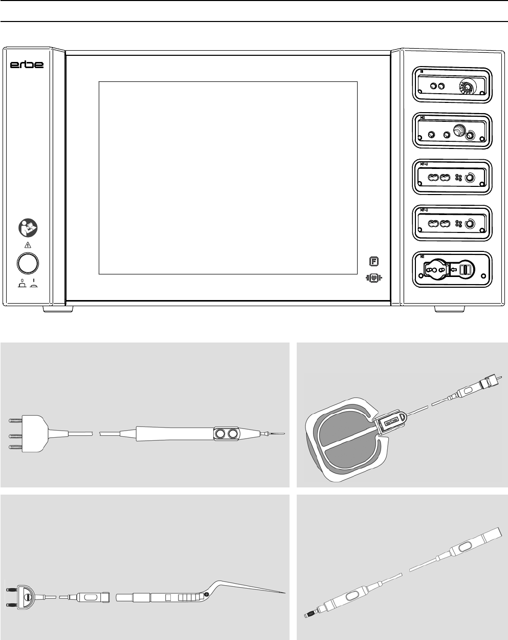
VIO 3 example accessories
Monopolar electrosurgical pencils, monopolar electrodes Patient plates
Bipolar instruments, bipolar forceps Connecting cables for electrosurgery
F
VIO 3
Dok.-Nr: D110127-EN, Ver.: 000, ÄM-Nr: 16446, Gültig ab: 10.05.16, Gedruckt: MZECEVIC/02.06.16, Ausdruck nicht maßstäblich und kein Original.Dok.-Nr: D110127-EN, Ver.: 000, ÄM-Nr: 16446, Gültig ab: 10.05.16, Gedruckt: MZECEVIC/02.06.16, Ausdruck nicht maßstäblich und kein Original.
37 / 158
3 • Accessories
80114-601
03.16
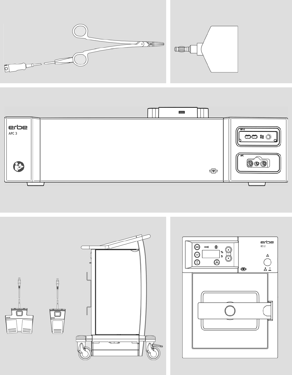
BiClamp and BiClamp LAP forceps Adapters for electrosurgery
APC 3 (unit for argon-plasma coagulation)
Accessories for ESU and modules IES 2 (smoke evacuation)
Dok.-Nr: D110127-EN, Ver.: 000, ÄM-Nr: 16446, Gültig ab: 10.05.16, Gedruckt: MZECEVIC/02.06.16, Ausdruck nicht maßstäblich und kein Original.Dok.-Nr: D110127-EN, Ver.: 000, ÄM-Nr: 16446, Gültig ab: 10.05.16, Gedruckt: MZECEVIC/02.06.16, Ausdruck nicht maßstäblich und kein Original.
3 • Accessories
38 / 158
80114-601
03.16
Use of APC instruments
You can only connect Erbe APC instruments with an integrated filter to the APC socket
of the APC 3. You can only set the mode, effect and argon flow within a specified range
wit these instruments.
Check compatibility of instrument and CUT / COAG mode with the help
of the Upmax display
1. Determine the electrical
capacity of the instrument
The maximum electrical capacity of the instrument is indicated on the instrument or
in the users manuals of the instruments. The unit of measurement for electrical capac-
ity is Vp. For example, an instrument can have a maximum electrical capacity of 5 kVp
(5000 Vp). Another instrument can have a maximum electrical capacity of 500 Vp. You
are not permitted to load the instrument beyond these values.
Example
You wish to operate an instrument that has a maximum electrical capacity of 500 Vp.
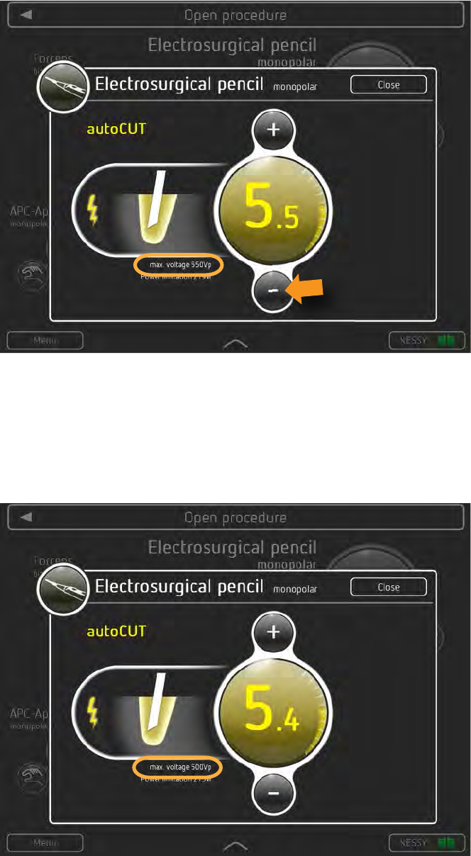
You wish to operate an instrument in autoCUT mode with effect 5.5. See the display
max. voltage in the CUT effect window.
2. Call up the CUT effect window 1. If the instrument symbol for the required instrument is not highlighted, touch the
relevant instrument symbol.
2. Touch the CUT effect display.
CAUTION
Electric load on instrument too high
The instrument can be damaged.
If the damaged area comes into contact with tissue, it can lead to
unintentional coagulation.
Determine the electrical capacity of the instrument. It is either
printed on the instrument or can be found in the user manual.
Compare the electrical capacity of the instrument with the max-
imum HF peak voltage of the required mode.
Observe the following instructions.
Dok.-Nr: D110127-EN, Ver.: 000, ÄM-Nr: 16446, Gültig ab: 10.05.16, Gedruckt: MZECEVIC/02.06.16, Ausdruck nicht maßstäblich und kein Original.Dok.-Nr: D110127-EN, Ver.: 000, ÄM-Nr: 16446, Gültig ab: 10.05.16, Gedruckt: MZECEVIC/02.06.16, Ausdruck nicht maßstäblich und kein Original.
39 / 158
3 • Accessories
80114-601
03.16
Fig. 3-1
The autoCUT mode with effect 5.5 would burden the instrument with a peak voltage
of 550 Vp. You must not operate the instrument with effect 5.5 in autoCUT mode. The
electrical capacity of the instrument (500 Vp) is lower than the maximum HF peak volt-
age (550 Vp) of the autoCUT mode with effect 5.5.
Reduce the effect. Touch the minus button until the HF peak voltage is equal to or
less than 500 Vp.
Fig. 3-2
The HF peak voltage (500 Vp) of the autoCUT mode with effect 5.4 is the same as the
electrical capacity of the instrument (500 Vp). You may work with this setting.
In the same way, you can test the compatibility of the instrument and COAG mode.
Touch the COAG effect display for this purpose.
Dok.-Nr: D110127-EN, Ver.: 000, ÄM-Nr: 16446, Gültig ab: 10.05.16, Gedruckt: MZECEVIC/02.06.16, Ausdruck nicht maßstäblich und kein Original.Dok.-Nr: D110127-EN, Ver.: 000, ÄM-Nr: 16446, Gültig ab: 10.05.16, Gedruckt: MZECEVIC/02.06.16, Ausdruck nicht maßstäblich und kein Original.
3 • Accessories
40 / 158
80114-601
03.16
Check compatibility of the return electrode
Depending on the return electrode (non-split or split), the Neutral Electrode Safety
System (NESSY) of the Erbe VIO and compatible return electrodes monitors various pa-
rameters:
•The unit / return electrode connection
•The skin / return electrode contact
•The application direction of the return electrode
Familiarize yourself in the chapter Safety Devices which individual parameters are
monitored. When using non-split return electrodes, the skin / return electrode contact
is not monitored.
When using third-party return electrodes, you must check in the accompanying papers
of the manufacturer whether the return electrode is suitable for the VIO used.
Compatible footswitches
You can only connect Erbe footswitches to the VIO 3. There is no footswitch for the
VIO 3 series.
CAUTION
Non-compatible or non-split return electrode
When applying a non-compatible return electrode, it should be ex-
pected that monitoring the contact between return electrode and
skin is faulty.
When applying a non-split return electrode, the contact between
return electrode and skin is not monitored. If contact between re-
turn electrode and skin is inadequate, the unit does not emit any
visual or acoustic warning signal.
Risk of burns for the patient under the return electrode!
Check in the accompanying papers of the manufacturer whether
the return electrode is suitable for the VIO device used.
Use only suitable return electrodes.
When applying a non-split return electrode: Regularly check the
return electrode for good skin contact.
Check in the accompanying papers of the manufacturer whether
the return electrode cable is suitable for the return electrode
used.
Use only suitable return electrode cables.
Dok.-Nr: D110127-EN, Ver.: 000, ÄM-Nr: 16446, Gültig ab: 10.05.16, Gedruckt: MZECEVIC/02.06.16, Ausdruck nicht maßstäblich und kein Original.Dok.-Nr: D110127-EN, Ver.: 000, ÄM-Nr: 16446, Gültig ab: 10.05.16, Gedruckt: MZECEVIC/02.06.16, Ausdruck nicht maßstäblich und kein Original.
41 / 158
4 • Description of the Controls
80114-601
03.16
Chapter 4
Description of the Controls
Controls on the front panel
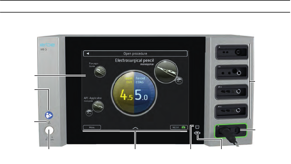
Fig. 4-1
Power switch
Unit on / off. The unit is only fully disconnected from the power supply once the power
cord is pulled out. Install the device such that the power cord can be pulled out without
problems.
Main screen
On the main screen you see all information and controls necessary for operating the
unit during an operation.
The main screen is the control center of the VIO 3. On this screen you can select the
instruments , set the instruments, monitor the return electrode and call up other
screens.
"F" icon
The symbol designates a constructional safety measure. The patient circuit is insulated
from ground. The danger of leakage currents and therefore the danger of burns is sub-
stantially reduced for the patient.
Icon: defibrillator discharge
All HF receptacles and the neutral electrode receptacle (applied parts) meet Type CF
requirements and are protected against the effects of defibrillator discharge.
Power switch
Symbol:
Read the
User Manual
Symbol: F Symbol:
Debrillator discharge
NE receptacle
Instrument
socket
Symbol:
Read the
Safety
Instructions
Touchscreen
Main screen
Dok.-Nr: D110127-EN, Ver.: 000, ÄM-Nr: 16446, Gültig ab: 10.05.16, Gedruckt: MZECEVIC/02.06.16, Ausdruck nicht maßstäblich und kein Original.Dok.-Nr: D110127-EN, Ver.: 000, ÄM-Nr: 16446, Gültig ab: 10.05.16, Gedruckt: MZECEVIC/02.06.16, Ausdruck nicht maßstäblich und kein Original.
4 • Description of the Controls
42 / 158
80114-601
03.16
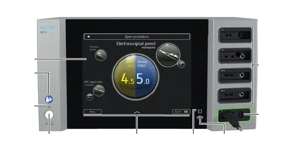
Fig. 4-2
Return electrode socket
Should you wish to activate the unit’s monopolar mode, you have to connect a return
electrode and apply it on the patient.
Instrument sockets
Connect HF instruments at these sockets.
Touchscreen
Touch-sensitive screen to set the VIO 3. The controls on the touchscreen change de-
pendent on the task currently undertaken. User your fingers to control the VIO 3.
Icon: read the user manual
Read the user manual before switching on and using the unit.
Symbol: Read the safety instructions
When reading the User Manual, pay special attention to the safety instructions.
Power switch
Symbol:
Read the
User Manual
Symbol: F Symbol:
Debrillator discharge
NE receptacle
Instrument
socket
Symbol:
Read the
Safety
Instructions
Touchscreen
Main screen
Dok.-Nr: D110127-EN, Ver.: 000, ÄM-Nr: 16446, Gültig ab: 10.05.16, Gedruckt: MZECEVIC/02.06.16, Ausdruck nicht maßstäblich und kein Original.Dok.-Nr: D110127-EN, Ver.: 000, ÄM-Nr: 16446, Gültig ab: 10.05.16, Gedruckt: MZECEVIC/02.06.16, Ausdruck nicht maßstäblich und kein Original.
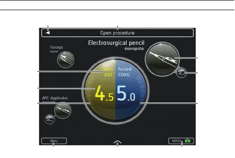
43 / 158
4 • Description of the Controls
80114-601
03.16
VIO 3 main screen
Fig. 4-3
On the main screen you see the symbols of the instruments stored in the program. A
series of further controls are also visible.
If you touch an instrument symbol, connect or activate the corresponding instrument,
the instrument symbol is highlighted (Example: monopolar electrode handle). In addi-
tion to information on the allocated activation type, you then obtain information on:
•CUT mode / COAG mode
•CUT effect / COAG effect
•Power output for CUT / COAG and progress display for sealing in the thermoSEAL
mode
Only if the instrument symbol is highlighted, can you change the instrument mode and
effect.
Menu button
If you touch the menu button you call up a menu to adapt a large number of unit set-
tings. These settings are explained in detail in the next chapter.
Arrow 1
If you touch Arrow 1, you call up the ‘Assign activation type’ field. Using symbols you
can assign footswitches, AUTO START and AUTO STOP to the instruments.
Menu button Arrow 1 NESSY button
Arrow 2 Program name
Instrument symbol
Activation type
COAG power display
CUT power display
CUT / COAG
mode displays
CUT / COAG
effect displays
Dok.-Nr: D110127-EN, Ver.: 000, ÄM-Nr: 16446, Gültig ab: 10.05.16, Gedruckt: MZECEVIC/02.06.16, Ausdruck nicht maßstäblich und kein Original.Dok.-Nr: D110127-EN, Ver.: 000, ÄM-Nr: 16446, Gültig ab: 10.05.16, Gedruckt: MZECEVIC/02.06.16, Ausdruck nicht maßstäblich und kein Original.
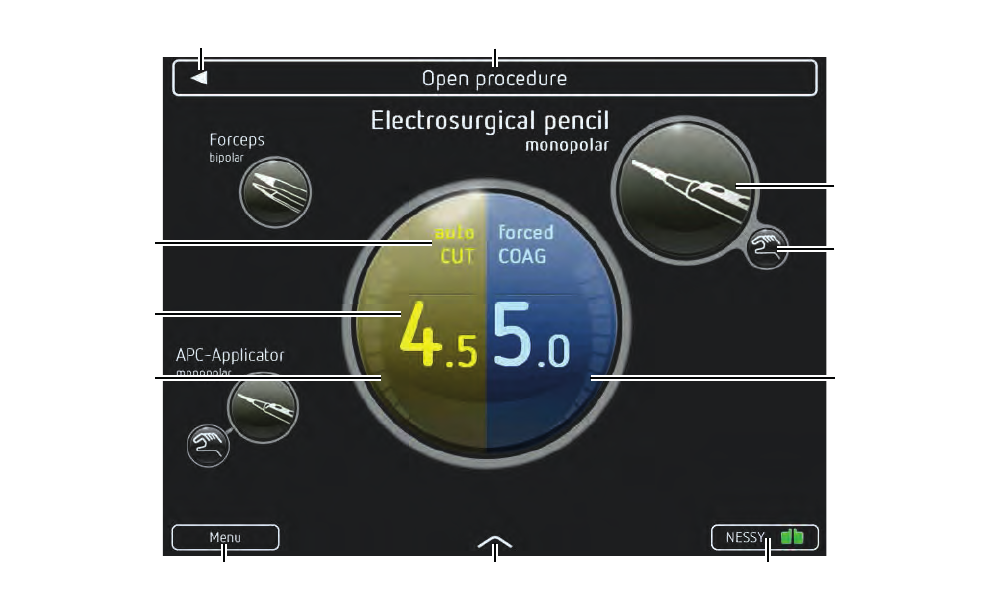
4 • Description of the Controls
44 / 158
80114-601
03.16
Fig. 4-4
NESSY button
The return electrode symbol provides information on what return electrode you have
connected: split or non-split. If the return electrode symbol is green, you can activate
monopolar modes. If the return electrode symbol is red, you cannot activate monopo-
lar modes.
If you touch the NESSY button, you call up the ‘return electrode monitoring’ window.
Here you receive information about the status of the return electrode. You can also
switch the neonatal monitoring on and off.
CUT and COAG power display
The segments of the CUT and COAG power displays show you whether and how much
power is output.
In the thermoSEAL mode, the display is a progress display for sealing.
Activation type
Shows the activation types assigned to the instrument.
Instrument symbol
The instrument symbols show the instruments in the program. If you connect an in-
strument which is not stored in the program, the unit displays an additional instrument
symbol.
If an instrument is connected to the unit, there is a connection between the instrument
symbol and the mode/effect displays. The outer circle of the instrument symbol is
highlighted white. No instrument is connected in the above fig.
If you touch an instrument symbol, you see the set modes and effects for the instru-
ment in the mode and effect displays.
Menu button Arrow 1 NESSY button
Arrow 2 Program name
Instrument symbol
Activation type
COAG power display
CUT power display
CUT / COAG
mode displays
CUT / COAG
effect displays
Dok.-Nr: D110127-EN, Ver.: 000, ÄM-Nr: 16446, Gültig ab: 10.05.16, Gedruckt: MZECEVIC/02.06.16, Ausdruck nicht maßstäblich und kein Original.Dok.-Nr: D110127-EN, Ver.: 000, ÄM-Nr: 16446, Gültig ab: 10.05.16, Gedruckt: MZECEVIC/02.06.16, Ausdruck nicht maßstäblich und kein Original.
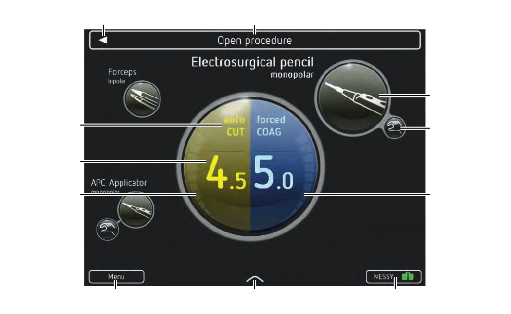
45 / 158
4 • Description of the Controls
80114-601
03.16
Fig. 4-5
Program name
Name of the selected program.
Arrow 2
If you touch Arrow 2, you call up the program list.
CUT and COAG mode displays
Displays the CUT and COAG mode for the selected instrument. If you touch the display,
you call up the window to change the mode.
CUT and COAG effect displays
Displays the CUT and COAG effect for the selected instrument. If you touch the display,
you call up the window to change the effect.
Menu button Arrow 1 NESSY button
Arrow 2 Program name
Instrument symbol
Activation type
COAG power display
CUT power display
CUT / COAG
mode displays
CUT / COAG
effect displays
Dok.-Nr: D110127-EN, Ver.: 000, ÄM-Nr: 16446, Gültig ab: 10.05.16, Gedruckt: MZECEVIC/02.06.16, Ausdruck nicht maßstäblich und kein Original.Dok.-Nr: D110127-EN, Ver.: 000, ÄM-Nr: 16446, Gültig ab: 10.05.16, Gedruckt: MZECEVIC/02.06.16, Ausdruck nicht maßstäblich und kein Original.
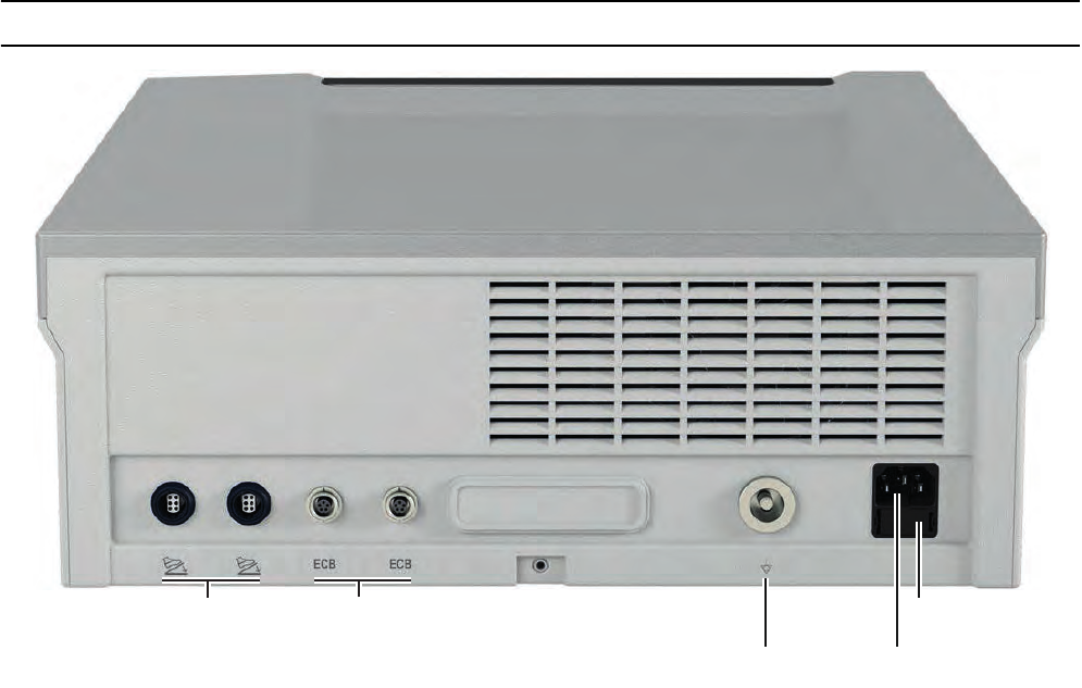
4 • Description of the Controls
46 / 158
80114-601
03.16
Controls on the back
Fig. 4-6
Footswitch sockets
You connect a two-pedal and a one-pedal footswitch to these sockets. The combina-
tions of two two-pedal footswitches or two one-pedal footswitches are not possible.
ECB sockets (Erbe Communication Bus)
These sockets serve to connect other units with the VIO 3.
Grounding terminal connection
If necessary, connect the grounding pin of the unit to the grounding system of the op-
erating room using a grounding cable.
Power connection
Connect the unit to a properly installed grounded power outlet. Only use the provided
power cord for this purpose. The power cord must bear the national test symbol.
Optionally, you can connect a power cord with V lock. The unit plug locks into the pow-
er connection of the VIO 3 and cannot loosen on its own.
Power fuses
The unit is protected with power fuses. If one of these power fuses has blown, the unit
may not be used on the patient again until it has been checked by a competent tech-
nician. The values of the power fuses are specified on the unit's rating plate. Only
spare fuses with these values may be used.
Footswitch sockets
Grounding terminal
Line fuses
Power connection
ECB sockets
Dok.-Nr: D110127-EN, Ver.: 000, ÄM-Nr: 16446, Gültig ab: 10.05.16, Gedruckt: MZECEVIC/02.06.16, Ausdruck nicht maßstäblich und kein Original.Dok.-Nr: D110127-EN, Ver.: 000, ÄM-Nr: 16446, Gültig ab: 10.05.16, Gedruckt: MZECEVIC/02.06.16, Ausdruck nicht maßstäblich und kein Original.

47 / 158
5 • Working with VIO 3
80114-601
03.16
Chapter 5
Working with VIO 3
Make power connection
The supply voltage must match the voltage specified on the unit's rating plate.
Connect the unit to a properly installed grounded power outlet. Only use the Erbe
power cord or an equivalent power cord for this purpose. The power cord must
bear the national test symbol. If the unit is installed on the VIO CART, make the
power connection with the power cord of the VIO CART.
Switching on, self-test
Use the power switch to switch the unit on. The unit then carries out a self-test
and tests all sockets. The units and footswitches connected are detected. All socket
frames are lit. You see the version number of the software on the display.
In the unit’s Further settings you can set which start screen you wish to start with after
the self-test:
•Program group list,
e.g. with the program groups Gynecology, General surgery
•Last used Program list,
e.g. the Gynecology program list with the programs Open Procedure, Laparoscopic
Procedure
•FocusView from the last used program
= main screen of the unit with symbols of the instruments stored in the program
and further controls
Although this setting is freely accessible, it should only be changed in coordination
with all those who use the unit.
These instructions start with the Program group list.
Dok.-Nr: D110127-EN, Ver.: 000, ÄM-Nr: 16446, Gültig ab: 10.05.16, Gedruckt: MZECEVIC/02.06.16, Ausdruck nicht maßstäblich und kein Original.Dok.-Nr: D110127-EN, Ver.: 000, ÄM-Nr: 16446, Gültig ab: 10.05.16, Gedruckt: MZECEVIC/02.06.16, Ausdruck nicht maßstäblich und kein Original.
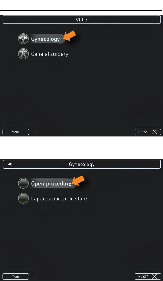
5 • Working with VIO 3
48 / 158
80114-601
03.16
Selecting the program
Fig. 5-1
1. Select a program group. Example: Gynecology
Fig. 5-2
2. Select a program. Example: Open Procedure
Dok.-Nr: D110127-EN, Ver.: 000, ÄM-Nr: 16446, Gültig ab: 10.05.16, Gedruckt: MZECEVIC/02.06.16, Ausdruck nicht maßstäblich und kein Original.Dok.-Nr: D110127-EN, Ver.: 000, ÄM-Nr: 16446, Gültig ab: 10.05.16, Gedruckt: MZECEVIC/02.06.16, Ausdruck nicht maßstäblich und kein Original.
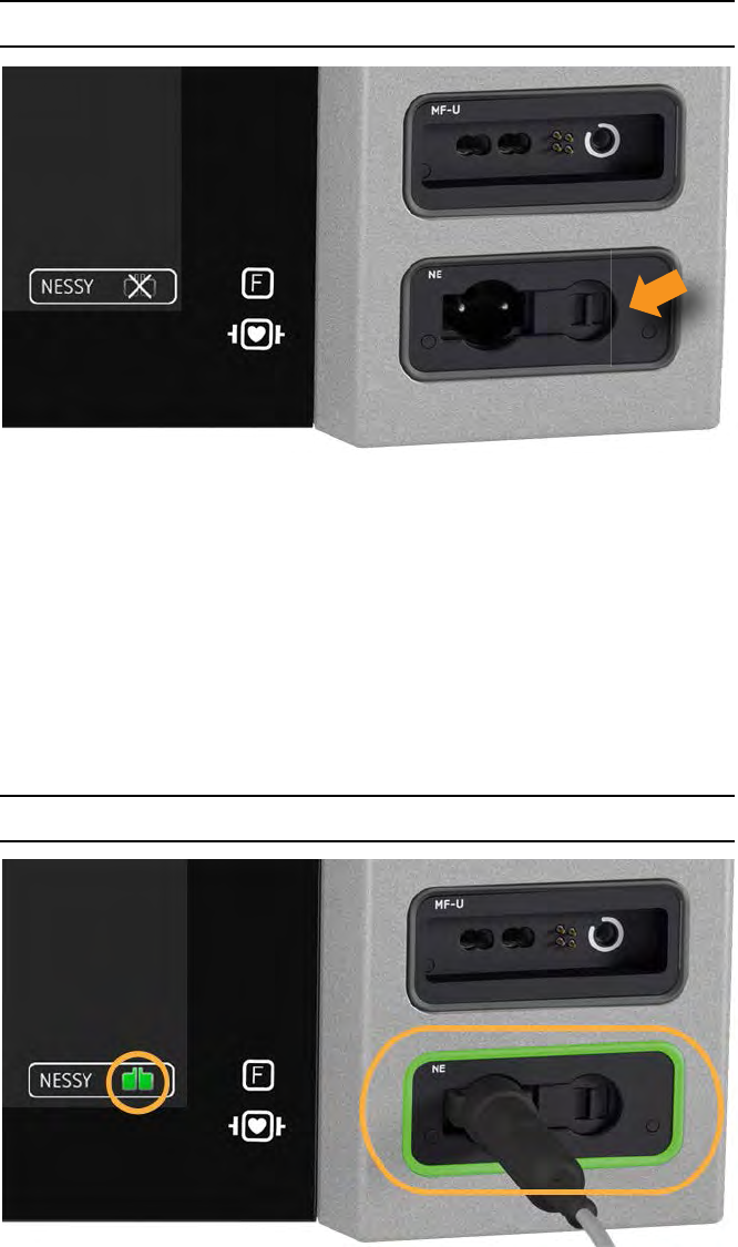
49 / 158
5 • Working with VIO 3
80114-601
03.16
Connecting return electrode, applying it on the patient
Fig. 5-3
1. Apply the return electrode on the patient.
2. Connect the return electrode cable to the return electrode socket.
Note: Under certain circumstances, the VIO 3 may ask you: Which return electrode type
have you just connected? You then have to make the decision between a split or a
non-split return electrode.
Make sure you actually connect the return electrode to the VIO 3 you register. Other-
wise, you cannot activate the monopolar modes.
Check return electrode
Fig. 5-4
If you have connected the return electrode correctly, the return electrode on the screen
lights green and the frame of the return electrode socket also lights green. The mo-
nopolar mode can be activated.
If the return electrode lights red or is crossed out, the frame of the return electrode
socket lights red or is not lit, touch the NESSY button to obtain assistance.
Read detailed information on the function of the return electrode in the Safety Devices
chapter. Here you also find assistance for various error situations.
Dok.-Nr: D110127-EN, Ver.: 000, ÄM-Nr: 16446, Gültig ab: 10.05.16, Gedruckt: MZECEVIC/02.06.16, Ausdruck nicht maßstäblich und kein Original.Dok.-Nr: D110127-EN, Ver.: 000, ÄM-Nr: 16446, Gültig ab: 10.05.16, Gedruckt: MZECEVIC/02.06.16, Ausdruck nicht maßstäblich und kein Original.
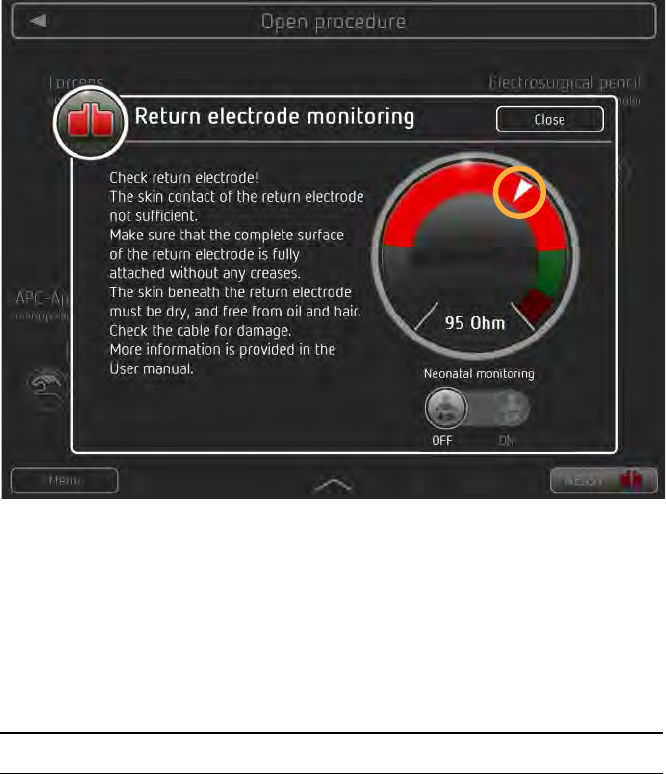
5 • Working with VIO 3
50 / 158
80114-601
03.16
Fig. 5-5
If a return electrode error arises during the operation, e.g. too little contact with the
patient's skin, a window for return electrode monitoring opens with a message.
An example for a message from return electrode monitoring is given in Fig. 5-5. In ad-
dition to the text, you see on the right a resistance display with resistance ranges. If
the needle is in the gray or red range, you cannot activate monopolar modes.
Connecting the first instrument
Connecting the instrument with the
aid of the pin configuration
Each instrument has a pin configuration showing the type and separations of the plug-
in contacts. Each socket has a pin configuration showing the type and separations of
the socket inputs. The pin configuration of the instrument and the socket must match.
1. Determine whether the instrument is monopolar or bipolar.
Monopolar instruments can be connected to monopolar sockets, multifunctional
sockets and MF-U sockets. Bipolar instruments can be connected to bipolar sock-
ets, multifunctional sockets and MF-U sockets. APC instruments must be connect-
ed to the APC sockets.
2. Consult the pin configuration of the instrument and socket.
3. Connect the instrument to the socket with suitable pin configuration.
If you plug the instrument into the wrong socket, the unit displays a message. Then
you cannot activate the unit.
Dok.-Nr: D110127-EN, Ver.: 000, ÄM-Nr: 16446, Gültig ab: 10.05.16, Gedruckt: MZECEVIC/02.06.16, Ausdruck nicht maßstäblich und kein Original.Dok.-Nr: D110127-EN, Ver.: 000, ÄM-Nr: 16446, Gültig ab: 10.05.16, Gedruckt: MZECEVIC/02.06.16, Ausdruck nicht maßstäblich und kein Original.
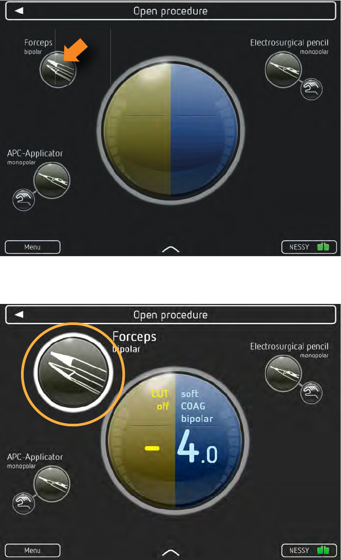
51 / 158
5 • Working with VIO 3
80114-601
03.16
Connecting the instrument with the
aid of the VIO 3
Fig. 5-6
1. Touch the instrument symbol. Example: Forceps bipolar
Fig. 5-7
The outer circle of the instrument symbol is flashing. The instrument symbol is high-
lighted.
Dok.-Nr: D110127-EN, Ver.: 000, ÄM-Nr: 16446, Gültig ab: 10.05.16, Gedruckt: MZECEVIC/02.06.16, Ausdruck nicht maßstäblich und kein Original.Dok.-Nr: D110127-EN, Ver.: 000, ÄM-Nr: 16446, Gültig ab: 10.05.16, Gedruckt: MZECEVIC/02.06.16, Ausdruck nicht maßstäblich und kein Original.
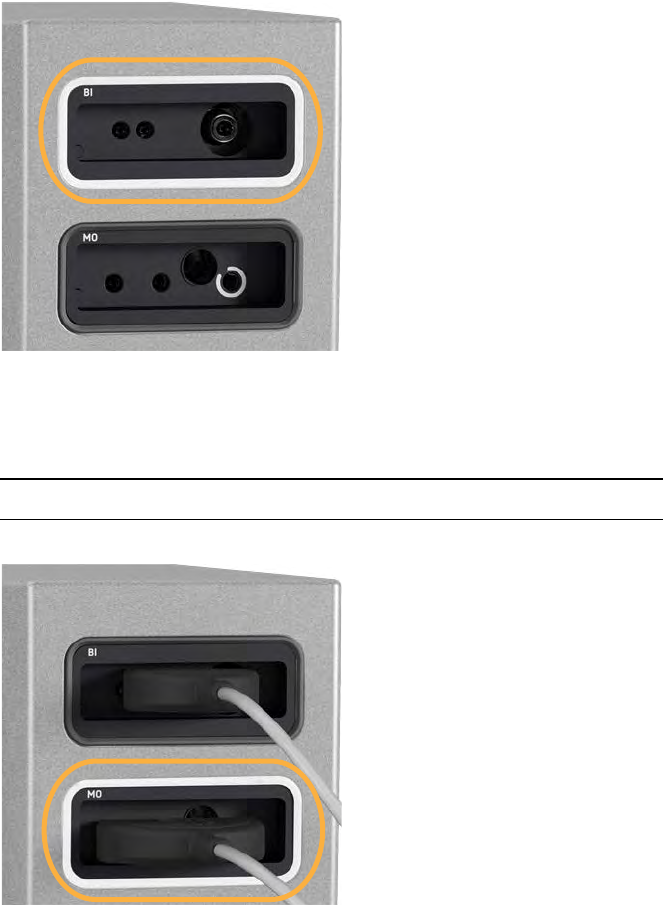
5 • Working with VIO 3
52 / 158
80114-601
03.16
Fig. 5-8
2. Connect the instrument to the socket with flashing socket frame.
Connecting a second instrument
Connect a second instrument. Example: Electrode handle monopolar
Fig. 5-9
After plugging in the instrument, the socket frame lights white. The instrument symbol
of the instrument is highlighted on the main screen.
Dok.-Nr: D110127-EN, Ver.: 000, ÄM-Nr: 16446, Gültig ab: 10.05.16, Gedruckt: MZECEVIC/02.06.16, Ausdruck nicht maßstäblich und kein Original.Dok.-Nr: D110127-EN, Ver.: 000, ÄM-Nr: 16446, Gültig ab: 10.05.16, Gedruckt: MZECEVIC/02.06.16, Ausdruck nicht maßstäblich und kein Original.
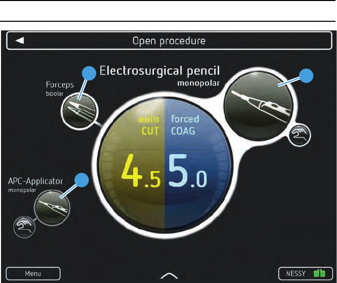
53 / 158
5 • Working with VIO 3
80114-601
03.16
Meaning of the instrument symbols in different displays
Fig. 5-10
If you touch an instrument symbol, connect or activate the corresponding instrument,
the instrument symbol is highlighted (Example: monopolar electrode handle). In addi-
tion to information on the allocated activation type, you then obtain information on:
•CUT mode / COAG mode
•CUT effect / COAG effect
•Power output for CUT / COAG and progress display for sealing in the thermoSEAL
mode
Only if the instrument symbol is highlighted, can you change the instrument mode and
effect.
The monopolar electrode handle (1) has just been plugged, activated or the corre-
sponding instrument symbol touched:
•The instrument symbol is highlighted in size.
•The outer circle of the instrument symbol is white.
•The instrument symbol is closely connected to the mode and effect displays.
You can check and change the instrument mode and effect in this display.
The bipolar forceps are connected to the unit (2):
•The outer circle of the instrument symbol is white.
•The instrument symbol is connected to the mode and effect displays with a thin
line.
The APC applicator is not connected to the unit (3):
•The outer circle of the instrument symbol is grayed out.
•The instrument symbol is not connected to the mode and effect displays.
1
2
3
Dok.-Nr: D110127-EN, Ver.: 000, ÄM-Nr: 16446, Gültig ab: 10.05.16, Gedruckt: MZECEVIC/02.06.16, Ausdruck nicht maßstäblich und kein Original.Dok.-Nr: D110127-EN, Ver.: 000, ÄM-Nr: 16446, Gültig ab: 10.05.16, Gedruckt: MZECEVIC/02.06.16, Ausdruck nicht maßstäblich und kein Original.
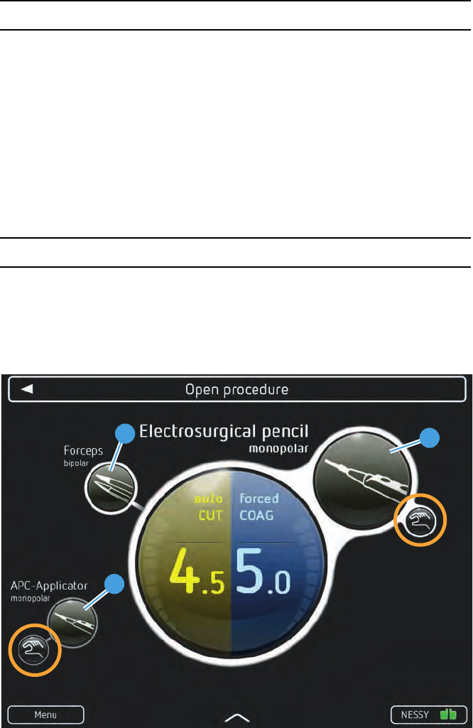
5 • Working with VIO 3
54 / 158
80114-601
03.16
Connecting an instrument which is not stored in the program
If required, you can connect instruments which are not stored in the program. The unit
then displays an additional instrument symbol on the main screen. Under certain cir-
cumstances, a window with an instrument list may open.
Select the instrument in the instrument list.
Note: The instrument additionally connected is not saved in the program. After switch-
ing off the unit, it no longer exists.
You can only save modified programs if you have access to the unit’s Protected set-
tings. See section: Overwrite modified program or save as a new program.
Checking program settings
In order to check the mode and effect settings of an instrument, the instrument symbol
has to be highlighted.
Prior to activation of instruments, check the program settings. You have to know
which instrument you are activating with which activation type and which mode
and effect settings.
Fig. 5-11
In the main screen you see at a glance which instruments are connected and which
activation type is assigned to them:
In the Open procedure example program, a monopolar electrode handle (1) and bipolar
forceps (2) are connected.
•The monopolar electrode handle (1) can be activated with the finger switch.
•The bipolar forceps (2) are not assigned any activation type. They cannot be acti-
vated.
•The APC applicator (3) is not connected. It could be activated with the finger
switch.
1
2
3
Dok.-Nr: D110127-EN, Ver.: 000, ÄM-Nr: 16446, Gültig ab: 10.05.16, Gedruckt: MZECEVIC/02.06.16, Ausdruck nicht maßstäblich und kein Original.Dok.-Nr: D110127-EN, Ver.: 000, ÄM-Nr: 16446, Gültig ab: 10.05.16, Gedruckt: MZECEVIC/02.06.16, Ausdruck nicht maßstäblich und kein Original.
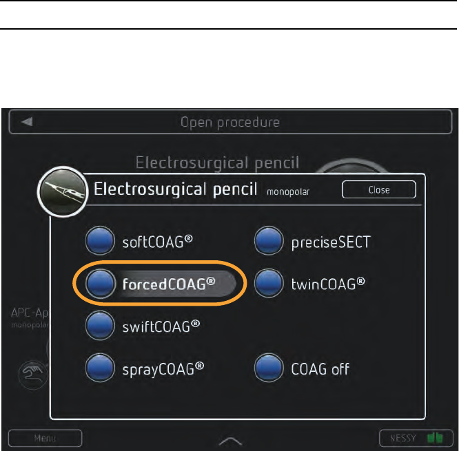
55 / 158
5 • Working with VIO 3
80114-601
03.16
In the Open procedure example program the instrument symbol for the monopolar
electrode handle (1) is touched. You would activate the instrument with the following
settings:
•autoCut, effect 4.5
•forcedCoag, effect 5.0
Changing mode and effect
Changing mode 1. If the instrument symbol for the required instrument is not highlighted, touch the
relevant instrument symbol.
2. Touch the CUT or COAG mode display.
Fig. 5-12
3. A window with an mode list opens. The active mode is highlighted gray (Example:
forcedCOAG). Touch the required mode.
Dok.-Nr: D110127-EN, Ver.: 000, ÄM-Nr: 16446, Gültig ab: 10.05.16, Gedruckt: MZECEVIC/02.06.16, Ausdruck nicht maßstäblich und kein Original.Dok.-Nr: D110127-EN, Ver.: 000, ÄM-Nr: 16446, Gültig ab: 10.05.16, Gedruckt: MZECEVIC/02.06.16, Ausdruck nicht maßstäblich und kein Original.
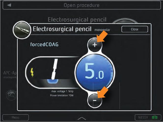
5 • Working with VIO 3
56 / 158
80114-601
03.16
Changing effect 1. If the instrument symbol for the required instrument is not highlighted, touch the
relevant instrument symbol.
2. Touch the CUT or COAG effect display.
Fig. 5-13
3. A window with an effect display opens (Example: forced COAG, effect 5.0). Select
the required effect with the + / - buttons.
4. Close the window.
Note: While you change the effect, the operating surgeon cannot activate the unit for
several seconds.
Note: The changes are not stored in the program. After switching off the unit, they no
longer exist.
You can only save modified programs if you have access to the unit’s Protected set-
tings. See section: Overwrite modified program or save as a new program.
Dok.-Nr: D110127-EN, Ver.: 000, ÄM-Nr: 16446, Gültig ab: 10.05.16, Gedruckt: MZECEVIC/02.06.16, Ausdruck nicht maßstäblich und kein Original.Dok.-Nr: D110127-EN, Ver.: 000, ÄM-Nr: 16446, Gültig ab: 10.05.16, Gedruckt: MZECEVIC/02.06.16, Ausdruck nicht maßstäblich und kein Original.
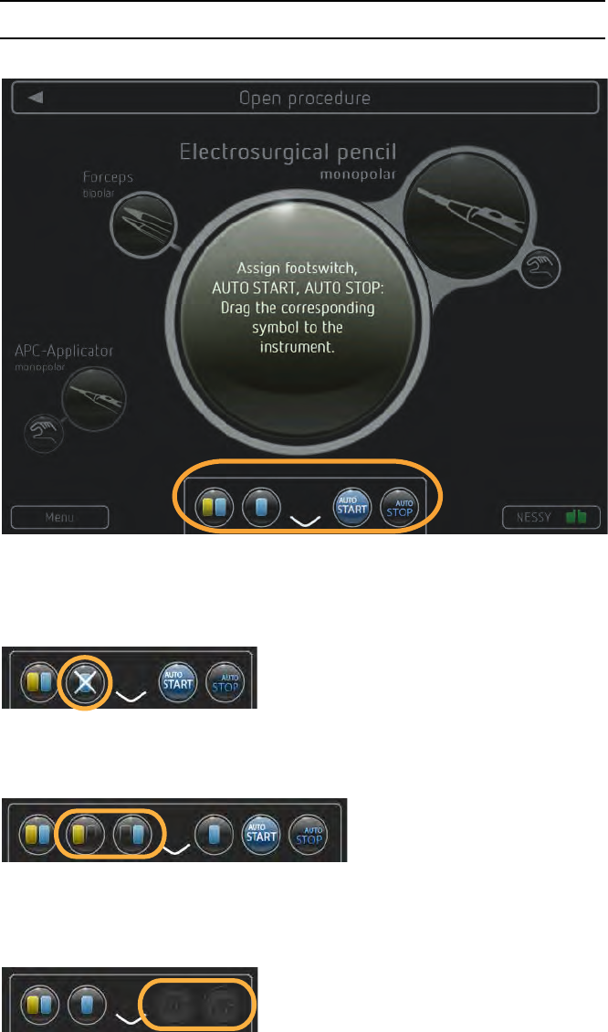
57 / 158
5 • Working with VIO 3
80114-601
03.16
Assigning activation type
Touch the arrow on the lower edge of the main screen (Arrow 1).
Fig. 5-14
The Assign activation type field opens. The field contains symbols for the activation
types two-pedal footswitch, one-pedal footswitch, AUTO START, AUTO STOP.
Meaning of the symbols in
different displays
Fig. 5-15
If a footswitch is not connected, the corresponding symbol is crossed out.
Fig. 5-16
If the “Assignment of two pedal footswitch” is permitted in the Protected Settings you
also see two symbols: CUT Pedal and COAG Pedal of the two-pedal footswitch.
Fig. 5-17
If the instruments stored in the program do not permit AUTO START or AUTO STOP, the
corresponding symbol is grayed out.
If the “Use of AUTO START” is blocked in the Protected settings , the corresponding
symbol is grayed out.
Dok.-Nr: D110127-EN, Ver.: 000, ÄM-Nr: 16446, Gültig ab: 10.05.16, Gedruckt: MZECEVIC/02.06.16, Ausdruck nicht maßstäblich und kein Original.Dok.-Nr: D110127-EN, Ver.: 000, ÄM-Nr: 16446, Gültig ab: 10.05.16, Gedruckt: MZECEVIC/02.06.16, Ausdruck nicht maßstäblich und kein Original.
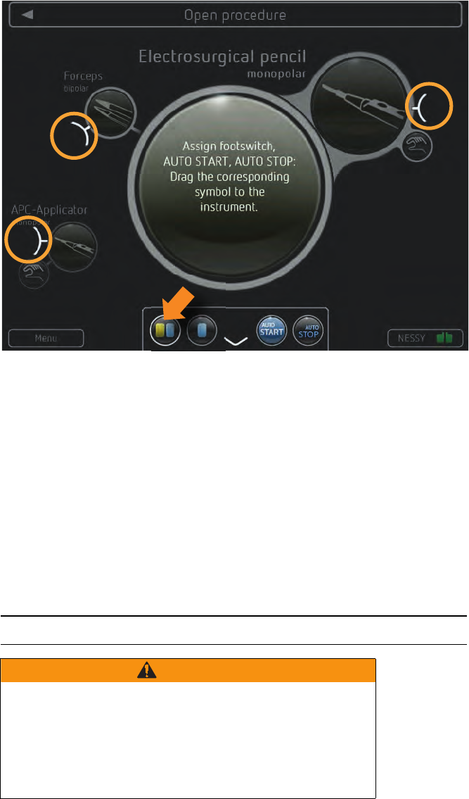
5 • Working with VIO 3
58 / 158
80114-601
03.16
Assigning activation type
Fig. 5-18
1. Touch a symbol. Example: Two-pedal footswitch
You see docking points on all instruments, which allow the selected activation type.
2. Drag the symbol to the docking point of the required instrument.
In the ‘Assign activation type’ field, the field is grayed out after assignment.
You can also drag symbols from one instrument to another.
Note: The changes are not stored in the program. After switching off the unit, they no
longer exist.
You can only save modified programs if you have access to the unit’s Protected set-
tings. See section: Overwrite modified program or save as a new program.
Activating VIO 3
WARNING
Activation of the unit with no knowledge of active settings
If the user does not understand the active settings of the unit, he
can cause the patient accidental tissue damage.
Check the active settings on the display of the unit, after: switch-
ing on the unit, connecting up an instrument, and changing the
program.
Dok.-Nr: D110127-EN, Ver.: 000, ÄM-Nr: 16446, Gültig ab: 10.05.16, Gedruckt: MZECEVIC/02.06.16, Ausdruck nicht maßstäblich und kein Original.Dok.-Nr: D110127-EN, Ver.: 000, ÄM-Nr: 16446, Gültig ab: 10.05.16, Gedruckt: MZECEVIC/02.06.16, Ausdruck nicht maßstäblich und kein Original.
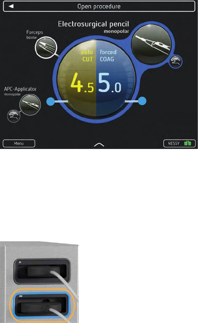
59 / 158
5 • Working with VIO 3
80114-601
03.16
Fig. 5-19
You can activate all instruments to which an activation type is assigned.
Operate the finger switch, footswitch or use AUTO START. Example: The monopolar
electrode handle is activated in COAG mode.
The outer circle of the mode and effect displays and the outer circle of the instrument
symbol lights up blue with COAG activation, yellow with CUT activation.
The segments of the CUT and COAG power displays (1) (2) show you whether and how
much power is output.
In the thermoSEAL mode, the display is a progress display for sealing.
Fig. 5-20
The socket frame of the activated instrument symbol lights up blue with COAG activa-
tion, yellow with CUT activation.
You hear an activation sound.
Note: You can also activate instruments whose settings you do not see. You should be
sure which settings you activate.
12
Dok.-Nr: D110127-EN, Ver.: 000, ÄM-Nr: 16446, Gültig ab: 10.05.16, Gedruckt: MZECEVIC/02.06.16, Ausdruck nicht maßstäblich und kein Original.Dok.-Nr: D110127-EN, Ver.: 000, ÄM-Nr: 16446, Gültig ab: 10.05.16, Gedruckt: MZECEVIC/02.06.16, Ausdruck nicht maßstäblich und kein Original.