Ecolab FAS1541 PSS Bed Beacon User Manual FCC Part 15
UltraClenz LLC. PSS Bed Beacon FCC Part 15
Ecolab >
Manual

3998 FAU Blvd. Suite 310 Boca Raton, FL 33431 Tel: 561-961-5585 Fax: 561-961-5587
Certification Exhibit
FCC ID: Z9O-FAS1541
IC: 10060A-FAS1541
FCC Rule Part: 15.209, 15.231, 15.249
IC Radio Standards Specification: RSS-210
ACS Project: 15-2042
Manufacturer: UltraClenz, LLC
Model: FAS1541-00
User Manual

Patient Safeguard System®
Patient Bed Installation
Revision 0.0
UltraClenz, LLC

Patient Safeguard System® Patient Bed Installation
UltraClenz, LLC
Page 1
Table of Contents
Abstract........................................................................................................................................................................................ 3
Revision History ........................................................................................................................................................................... 3
Reference Documents ................................................................................................................................................................. 3
Terms, Acronyms and Abbreviations ........................................................................................................................................... 3
1. Introduction to the Patient Safeguard System (PSS) ............................................................................................................... 4
1.1 Hardware Components ...................................................................................................................................................... 4
1.1.1 Healthcare Worker Badge ........................................................................................................................................... 4
1.1.2 Dispenser Beacon ....................................................................................................................................................... 4
1.1.3 Bed Beacon ................................................................................................................................................................. 4
1.2 Bentley Wireless Network ................................................................................................................................................. 4
1.2.1 Hubs ............................................................................................................................................................................ 4
1.2.2 Gateway ...................................................................................................................................................................... 4
1.3 Dashboard and Offsite Server ............................................................................................................................................ 5
2. Required Materials .................................................................................................................................................................. 6
3. PSS Patient Bed Installation Functions .................................................................................................................................... 7
4. Installation ............................................................................................................................................................................... 8
4.1 Bed Beacon Mount Installation ......................................................................................................................................... 8
4.2 Bed Beacon Installation ..................................................................................................................................................... 8
4.3 AC Line Power Sensor (ALP) ............................................................................................................................................... 9
4.4 Cable Management ............................................................................................................................................................ 9
5. Adjusting the Communication Range .................................................................................................................................... 10
5.1 Range Adjustment on Bed Beacon .................................................................................................................................. 10
5.2 Bed Beacon to Test Badge Range Adjustment ................................................................................................................. 11
5.3 Dashboard Test with the PSS Badge and Bed Beacon ..................................................................................................... 12
6. Metadata Entry ...................................................................................................................................................................... 16
6.1 New Bed Beacon Metadata Entry .................................................................................................................................... 16
6.2 Replacing an Existing Bed Beacon – Swapping Metadata................................................................................................ 17
7. Troubleshooting ..................................................................................................................................................................... 18
7.1 No Bed Beacon Heartbeats on the Dashboard ................................................................................................................ 18
7.2 The Bed Installation Does Not Communicate with a Badge ............................................................................................ 18
7.3 Bed Beacon FAS1541 ....................................................................................................................................................... 18
8. System Component Care and Maintenance .......................................................................................................................... 19
8.1 Cleaning the Components ................................................................................................................................................ 19
8.2 Handling the Bed Beacon ................................................................................................................................................. 19
8.3 Battery Replacement ....................................................................................................................................................... 19
Appendix A - Certification and Safety Approvals ....................................................................................................................... 20

Patient Safeguard System® Patient Bed Installation
UltraClenz, LLC
Page 2
FCC Statement ....................................................................................................................................................................... 20
Industry Canada ..................................................................................................................................................................... 20
Appendix B - Warranty .............................................................................................................................................................. 21
Appendix C – Bed Label ............................................................................................................................................................. 22
Figures
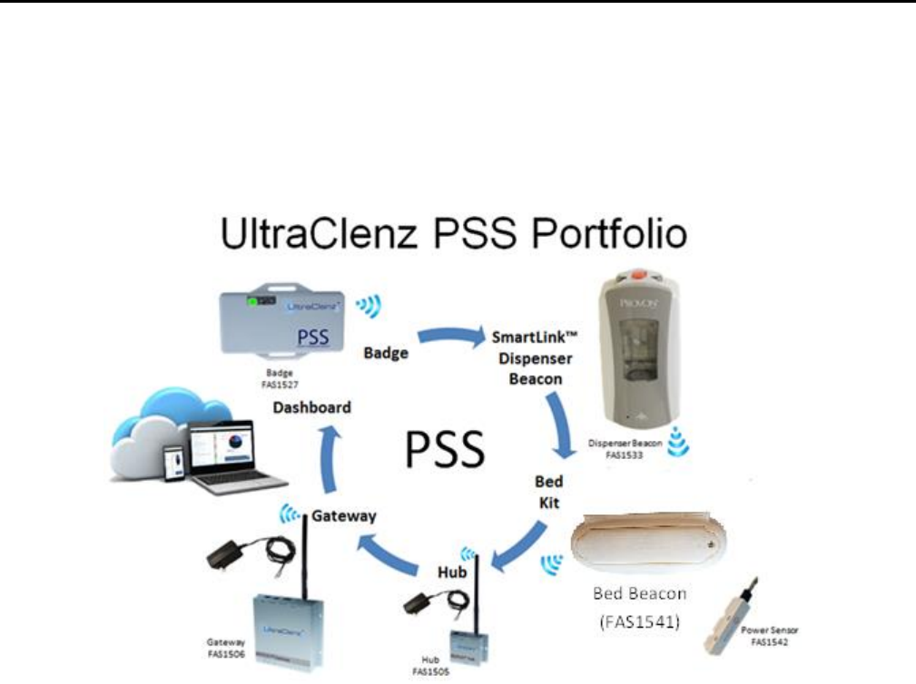
Patient Safeguard System Overview ............................................................................................................................................ 5
Figure 1. Bed Installation Components ................................................................................................................................. 7
Figure 2. Bed Beacon Details ................................................................................................................................................ 7
Figure 3. Bed Beacon Mounted on Patient Bed Model Hill-Rom Versa Care P3200 ............................................................ 8
Figure 4. Bed Beacon Installation ......................................................................................................................................... 8
Figure 5. AC Line Power Sensor Attached to Power Cord ..................................................................................................... 9
Figure 6. ALPS Cable Routing and Cable Tie Holder Placement ............................................................................................ 9
Figure 7. ALP Sensor Cable Routing and Cable Tie Holder Placement ................................................................................ 10
Figure 8. ALP Sensor Cable Routing to Bed Beacon and Cable Tie Holder Placement ........................................................ 10
Figure 9. Bed Beacon Range Adjustments .......................................................................................................................... 11
Figure 10. Test Badge Height Is 50 Inches From the floor .................................................................................................... 11
Figure 11. Test Badge Activation Distance from Bed’s Handrail Center is 24” ................................................................... 12
Figure 12. Dashboard Entry Screen....................................................................................................................................... 12
Figure 13. First Screen of Dashboard .................................................................................................................................... 13
Figure 14. Choose Device Screen .......................................................................................................................................... 13
Figure 15. Device Bed Beacon Screen ................................................................................................................................... 14
Figure 16. Choose the Search for Bed Beacon ...................................................................................................................... 14
Figure 17. Search for and See Device Screen ........................................................................................................................ 15
Figure 18. PSS Event Screen .................................................................................................................................................. 15
Figure 19. Active Bed Beacon List ......................................................................................................................................... 16
Figure 20. Bed Beacon Metadata .......................................................................................................................................... 17
Figure 21. Replace Icon ......................................................................................................................................................... 17
Figure 22. Replace Device Tab .............................................................................................................................................. 18
Figure 23. Battery Cover ....................................................................................................................................................... 19

Patient Safeguard System® Patient Bed Installation
UltraClenz, LLC
Page 3
Abstract
This document covers the basic operation of the Bed Installation and its components. Also covered is the installation of the
various components used in a Bed Installation.
Revision History
Revision
Date
By
Description
0
08/12/15
AP
Initial Release
Reference Documents
Patient Safeguard System™ Healthcare Worker Badge User’s Guide, DOC1046.
Terms, Acronyms and Abbreviations
Bentley
UltraClenz’ Proprietary Wireless Network
HCW
Healthcare Worker
LED
Light Emitting Diode
POST
Power On Self-Test
PSS
Patient Safeguard System
ALPS
AC Line Power Sensor
AC
Alternating Current (Bed 120 volt power from wall socket)

Patient Safeguard System® Patient Bed Installation
UltraClenz, LLC
Page 4
1. Introduction to the Patient Safeguard System (PSS)
The Patient Safeguard System is a state of the art wireless hand hygiene reminder system designed to enable best practices
for proper hand hygiene in a healthcare facility. Multiple studies from organizations like the World Health Organization
(WHO) and the Centers for Disease Control (CDC) have repeatedly demonstrated that proper hand hygiene leads directly to
improved infection control and a reduction in Healthcare Associated Infections (HAI). The PSS is a cost-effective, energy
efficient, robust and easily installed system for coaching healthcare workers (HCWs) to always wash or sanitize their hands
before and after patient contact. The system can be divided into three parts, hardware components, the Bentley Wireless
Network and the Dashboard web-based application.
1.1 Hardware Components
The PSS is built on individual components or devices that work in concert to deliver real-time individual hand hygiene
status to HCWs and near real-time statistics for both onsite and offsite monitoring of current and historical hand
hygiene compliance data. Currently, the components of PSS are the HCW Badge, the Dispenser Beacon and the Bed
Beacon.
1.1.1 Healthcare Worker Badge
The Badge is a wireless device worn by the HCW to provide real-time notification of the HCW’s current hand hygiene
status. Notification is provided by both visual and audible alerts. The Badge is responsible for determining,
maintaining and transmitting the current hand hygiene status of the HCW to other PSS components.
1.1.2 Dispenser Beacon
The Dispenser Beacon is attached to or embedded within a soap or sanitizer dispenser. Its function is to
communicate with the Badge worn by the HCW when the dispenser is activated (dispense event), collect dispense
event data from that Badge and then transmit the collected data to a network where it will ultimately be sent to an
offsite server for processing and archiving.
1.1.3 Bed Beacon
The Bed Beacon, along with its internal low frequency antenna, is mounted to a patient bed. Its function is to
communicate with the Badge worn by the HCW when the HCW comes in close proximity with the patient bed (bed
event), collect bed event data from that Badge and then transmit the collected data to a network where it will
ultimately be sent to an offsite server for processing and archiving.
1.2 Bentley Wireless Network
Bentley is a wireless mesh network used to transport event data collected by Dispenser Beacons and Bed Beacons to the
offsite server for processing and archiving. Bentley is composed of two types of devices, Hubs and a Gateway.
1.2.1 Hubs
Hubs are installed throughout a healthcare facility and communicate with nearby Bed Beacons and Dispenser
Beacons. When an event is generated by a Beacon, it broadcasts the event data to the nearest Hub. The Hub then
receives the event data and rebroadcasts it to the Gateway (if it is in range) or the next nearest Hub where the data
is passed from Hub to Hub until it reaches the Gateway.
1.2.2 Gateway
The Gateway receives event data generated by Dispenser Beacons or Bed Beacons directly, if they are in range, or
from Hubs which act as repeaters. The Gateway then transmits the event data to an offsite server via cellular
modem for processing and archiving.
Patient Safeguard System® Patient Bed Installation
UltraClenz, LLC
Page 5
1.3 Dashboard and Offsite Server
The Dashboard is a web-based application running on a designated offsite server. It is responsible for collecting,
processing and archiving onsite Dispenser Beacon and Bed Beacon event data sent by the onsite Gateway. The
Dashboard provides a user interface which allows access to hand hygiene data, statistics and reports compiled from
event data originating at the healthcare facility.
Patient Safeguard System Overview
Patient Safeguard System® Patient Bed Installation
UltraClenz, LLC
Page 6
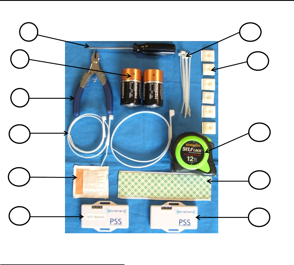
2. Required Materials
The materials needed for this install:
(A) Small Phillips screwdriver
(B) D cell alkaline batteries (2 ea.)
(C) Wire cutters
(D) Cable Ties 14in long (4ea.)
(E) Alcohol Wipe
(F) Test Badge (FAS1527)
(G) HCW Badge (FAS1527)
(H) Double sided tape
(I) Tape Measuring device
(J) Cable Tie Holder (10ea.)
(K) Cable Tie 4in long (10ea.)
A
B
C
D
G
E
F
H
K
I
J
Patient Safeguard System® Patient Bed Installation
UltraClenz, LLC
Page 7
The Patient Bed installation is comprised of three main components. The first component is the Bed beacon which is used
to create a zone around the patient bed and controls the zone around a patient bed. The second component is the AC Line
Power Sensor that senses when bed is connected or disconnected from AC power. The third component is the Bed Mount
which the Bed Beacon clips onto.
Figure 1. Bed Installation Components
3. PSS Patient Bed Installation Functions
The Bed Beacon works with the internal antenna to create a zone around a patient bed, referred to as the patient zone.
When a healthcare worker (HCW) wearing a Badge enters the zone, the Bed Beacon wirelessly communicates with the
Badge and lets the Badge know that it has entered the zone around a specific patient bed. The Bed Beacon will emit an
audible beep and flash a green LED when it has successfully communicated with the Badge. If communications with the
Badge are successful the Bed Beacon then sends information about its interaction with the Badge to the server via the
Bentley wireless network. For more information about how the Badge will react to being in the patient zone, please read
the document Patient Safeguard System® Healthcare Worker Badge User’s Guide (DOC1046).
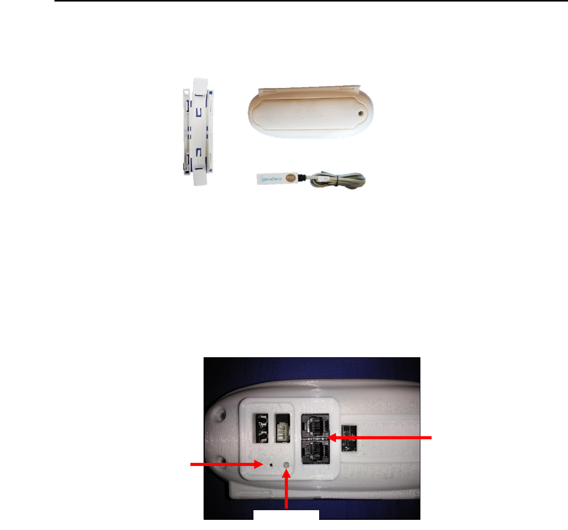
Figure 2. Bed Beacon Details
When the Bed Beacon is mounted on a bed and connected to the AC Line Power Sensor through the RJ11 jacks, it detects
when the bed is connected to the wall outlet. This will cause the Bed Beacon to emit a beep and flash a green LED. Each
time the state of the bed’s AC power changes state the Bed Beacon will send a message over the Bentley network. If the
bed’s power cord is disconnected from AC wall power the patient zone will be turned off while the bed is in transit. When
the ALP Sensor loses AC detection the Bed Beacon will emit 1 beep and flash 1 red LED. When the bed is brought back into
the room and bed AC power is restored the Bed Beacon will emit 1 beep and flash 1 green LED. Each time any device is
connected or disconnected from the Bed Beacon, the Bed Beacon will send a message over the Bentley network.
Bed Antenna (FAS1540)
Status LED’s
Audio port
AC Line Power Sensor (FAS1542)
AC Line Power Sensor (FAS1542)
Bed Beacon (FAS1541)
RJ11 Connectors
Bed Mount
Patient Safeguard System® Patient Bed Installation
UltraClenz, LLC
Page 8
4. Installation
4.1 Bed Beacon Mount Installation
The Bed Beacon Mount can be mounted directly to the frame of the bed itself (see Figure 3).
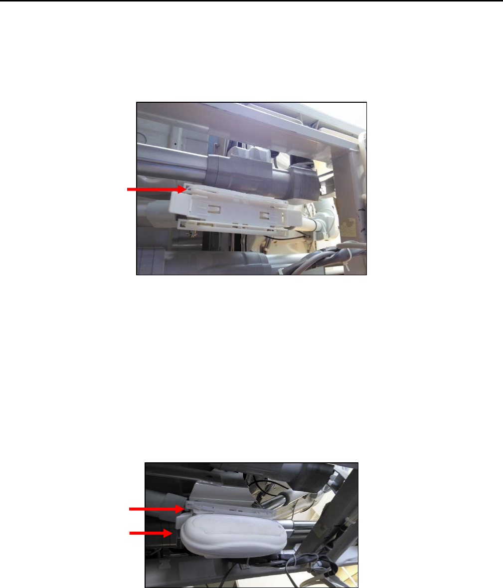
Figure 3. Bed Beacon Mounted on Patient Bed Model Hill-Rom Versa Care P3200
Tape mounting
Mount the Bed Beacon Mount onto the metal surface with the double-sided tape (supplied) and secure with the 14”
long cable tie. Make sure the Bed Mount and the mounting surface are clean and free of dirt and oil. Spray a
mixture of Dawn soap (1% of Dawn soap per a gallon of water) and scrub the mounting surface with a plain Scotch-
Brite scouring pad. Wipe the surface with a lint free cloth to clean off any contaminants. Then use a soft cloth
dampened with isopropyl alcohol to further clean the mounting surface. Repeat the process as necessary. Ensure the
mounting surface is dry before attaching antenna and firmly push and hold in place for several minutes (see Figure
3).
4.2 Bed Beacon Installation
The Bed Beacon (see Figure 4) chips directly into the Bed Beacon Mount.
Figure 4. Bed Beacon Installation
Bed Beacon
14” Long
Cable Tie
Bed Beacon Mount
Patient Safeguard System® Patient Bed Installation
UltraClenz, LLC
Page 9
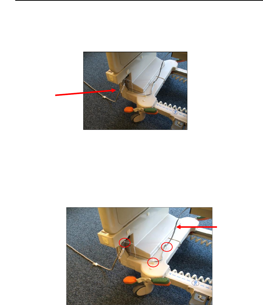
4.3 AC Line Power Sensor (ALP)
The AC Line Power Sensor (see Figure 6) is mounted onto the bed’s AC power cord (3” from cable gland). The ALP
Sensor senses the AC power of the patient bed cord to activate or deactivate the Bed Beacon during the bed’s
connect or disconnect, for transit to another location. The ALP Sensor is attached directly to the Dock via a small
cable. It mounts to bed’s power cord with 2 cable ties. Make sure a service loop is left in the ALP Sensor’s cable run,
allowing for the bed to be raised and lowered.
Figure 5. AC Line Power Sensor Attached to Power Cord
Cable Tie mounting
Mount the AC Line Power Sensor on the patient bed’s AC power cord using 2 cable ties (see Figure 5). Use cable tie
holders for routing the wire to the Dock, and make sure the mounting surface is clean and free of dirt and oil. A soft
cloth dampened with isopropyl alcohol works well to clean both surfaces.
4.4 Cable Management
1. Place cable tie holders, cable ties and route cable to the Bed Beacon as shown (see Figure 6, 7 & 8). Make sure
the mounting surfaces are clean and free of dirt and oil. A soft cloth dampened with isopropyl alcohol works well to
clean the mounting surfaces.
Figure 6. ALPS Cable Routing and Cable Tie Holder Placement
AC Line Power Sensor
attached to power cord
Service Loop (17”)
Patient Safeguard System® Patient Bed Installation
UltraClenz, LLC
Page 10
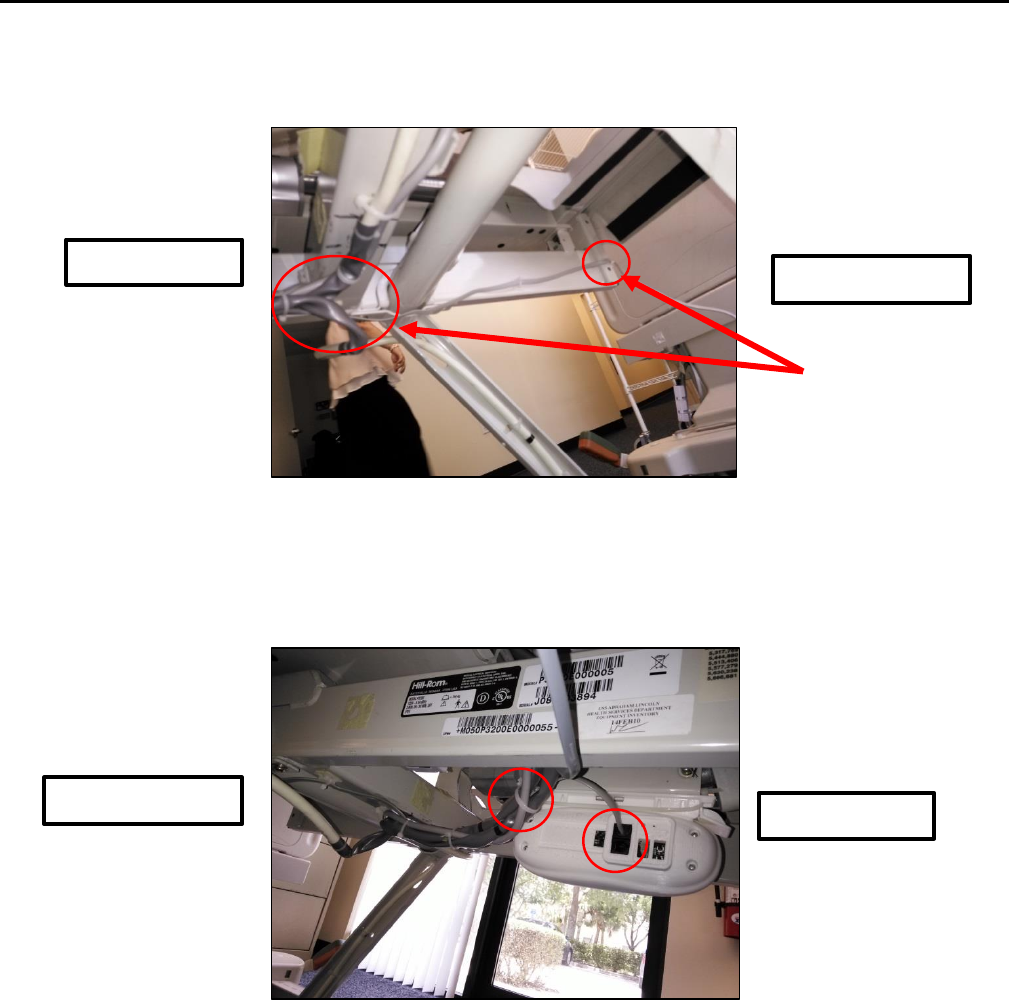
2. Place cable tie holders and route the ALP Sensor cable along the inside rail and tie down any excess cable (Service
Loop) as shown (see Figure 7).
Figure 7. ALP Sensor Cable Routing and Cable Tie Holder Placement
1. Place a cable tie holder and route the ALP Sensor cable as shown (see Figure 8).
Figure 8. ALP Sensor Cable Routing to Bed Beacon and Cable Tie Holder Placement
5. Adjusting the Communication Range
5.1 Range Adjustment on Bed Beacon
The Bed Beacon communication range is adjusted during installation to maximize communication with the healthcare
worker Badge. To adjust the communication range, the range buttons are located on the back of the Bed Beacon. The
Bed Beacon communication range is adjusted by repeatedly pushing either the “+” increment or the “–“decrement
range buttons (see Figure 9) to achieve the desired range. The total adjustable range of the Bed Beacon is 1 to 15
increments between the lowest and the highest setting. Each push of the “+” button will produce an audible beep and
the green LED will flash once indicating one (1) increment up. When the highest setting is reached, two (2) audible
Head of the bed
Foot of the bed
Head of the bed
Foot of the bed
Tie Downs
Patient Safeguard System® Patient Bed Installation
UltraClenz, LLC
Page 11
beeps will be heard and two (2) green LED flashes will be visible. Each push of the “-” button will produce an audible
beep and the red LED will flash once indicating one (1) increment down. When the lowest setting is reached, two (2)
audible beeps will be heard and two (2) red LED flashes will be visible. To reset a Bed Beacon’s range back to the factory
default setting, push and hold both of the “+” and “–“ buttons at the same time. Four (4) audible beeps will be heard
and the LEDs will flash in an alternating pattern between green and red. The factory default range setting for the Bed
Beacon is position 9. Replace the battery cover when the adjustment is complete.
Figure 9. Bed Beacon Range Adjustments
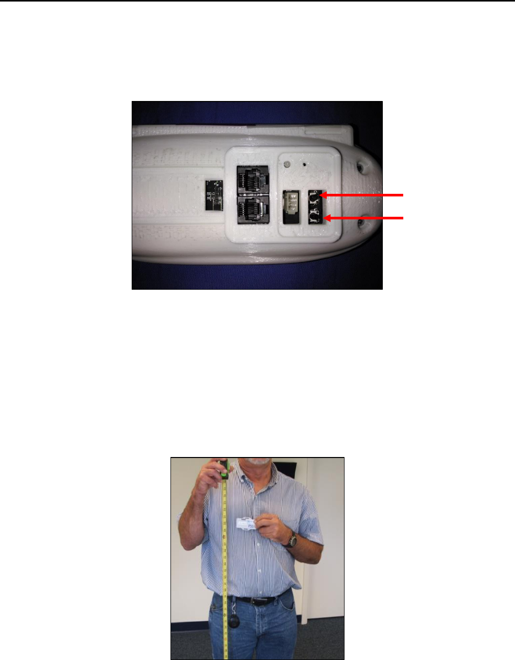
5.2 Bed Beacon to Test Badge Range Adjustment
2. Set and adjust the bed and mattress height to the average height for beds in the facility.
3. While holding the Test Badge 50 inches from the floor and 24 inches from the bed’s handrail center location
(side of bed) (see Figures 10 & 11), the Test Badge’s red and yellow LEDs should flash once a second, indicating
that the proper activation range and communication have been successfully established. If range is not 24”
adjust the Bed Beacon’s range buttons until the Badge activation range is 24 inches (see Figure 9).
Figure 10. Test Badge Height Is 50 Inches From the floor
Decrement “-“
Increment “+”
Patient Safeguard System® Patient Bed Installation
UltraClenz, LLC
Page 12
Figure 11. Test Badge Activation Distance from Bed’s Handrail Center is 24”
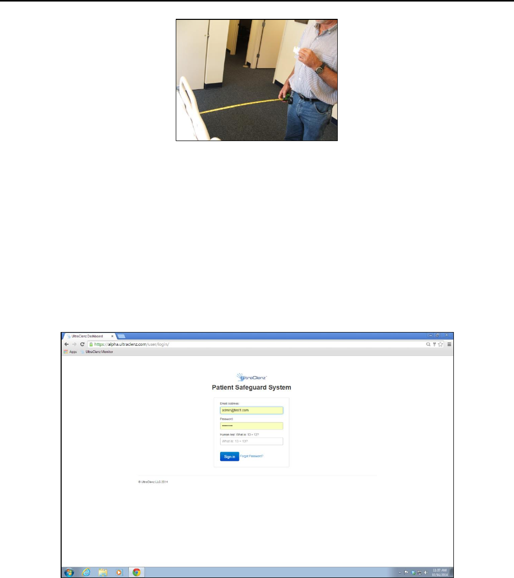
5.3 Dashboard Test with the PSS Badge and Bed Beacon
1. With the HWC Badge, verify that the Bed Beacon and Badge activates at 24 x 50 inches, and that Badge’s device
address is confirmed and verified on the dashboard.
2. Go to Google (Internet) and type your facility’s Dashboard URL and you should see Figure 12.
3. Type in the correct email address, password, and answer the math question correctly to sign in.
Figure 12. Dashboard Entry Screen
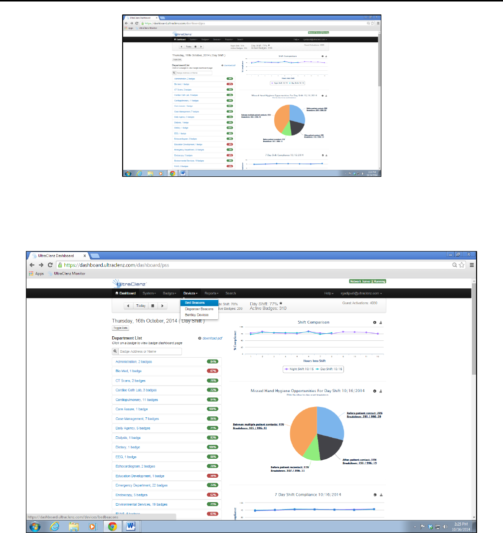
4. When access is granted you should see the screen shown in Figure 13.
Patient Safeguard System® Patient Bed Installation
UltraClenz, LLC
Page 13
Figure 13. First Screen of Dashboard
5. Click on Device and Bed Beacon as shown in Figure 14.
Figure 14. Choose Device Screen
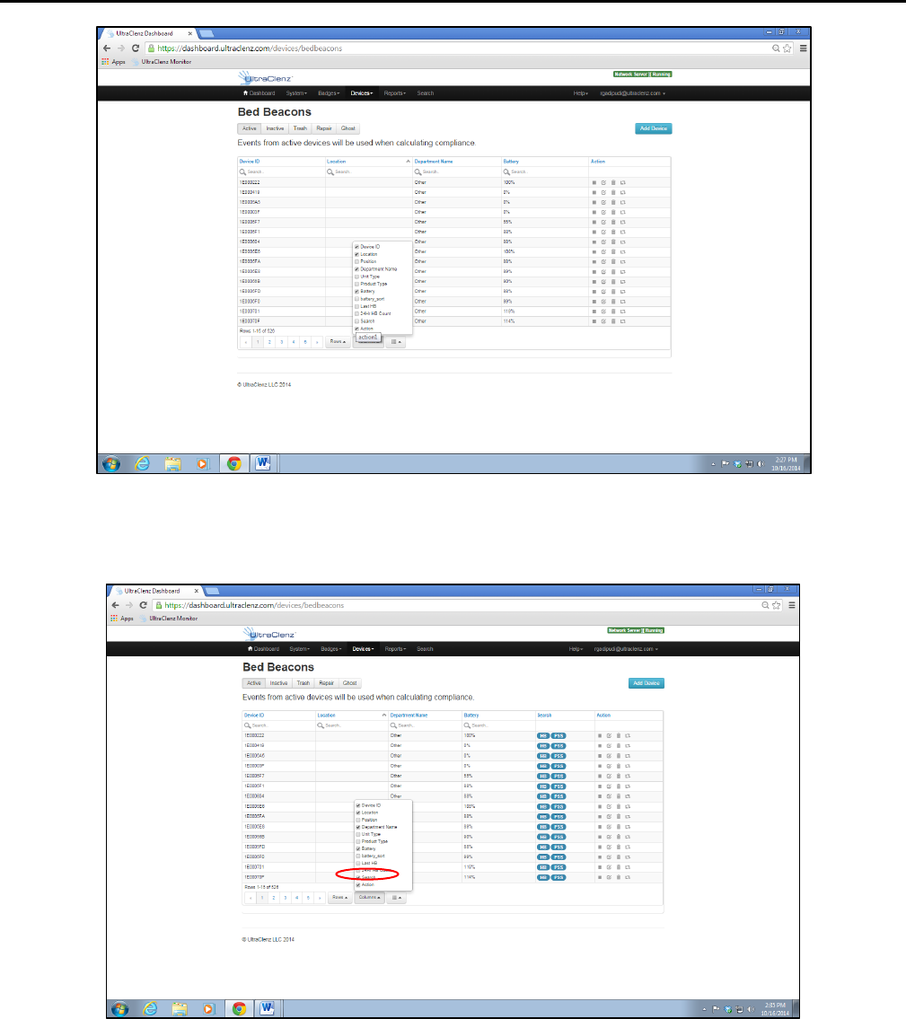
6. Click on Column and you should see the choose selection block as shown in Figure 15.
Patient Safeguard System® Patient Bed Installation
UltraClenz, LLC
Page 14
Figure 15. Device Bed Beacon Screen
7. Check the box Search choice as shown in Figure 16.
Figure 16. Choose the Search for Bed Beacon
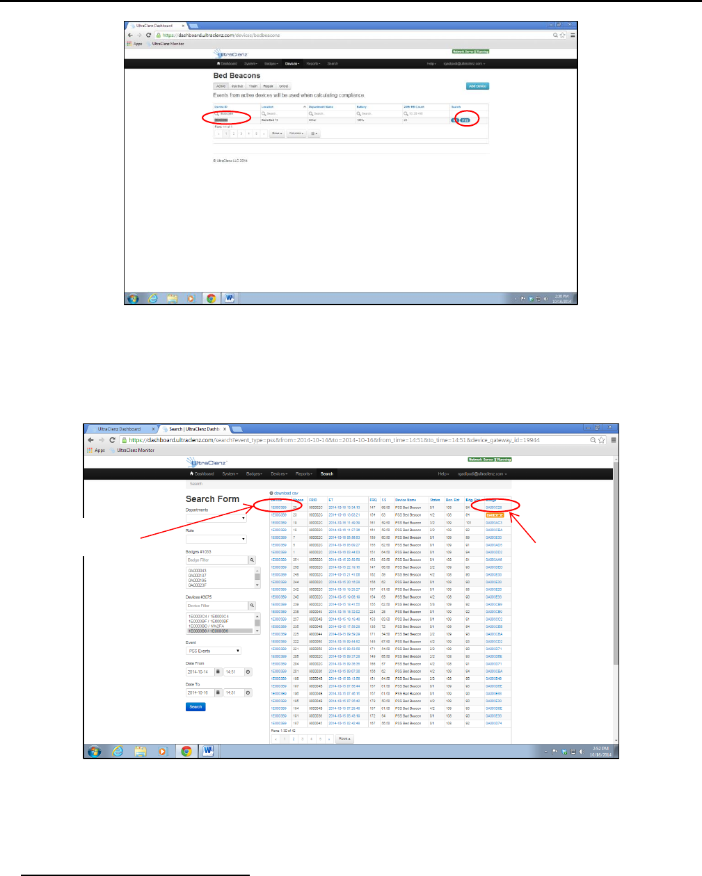
8. Enter the Bed Beacon’s device address number as shown in Figure 17 and the device should be found as shown.
Click on the PSS button shown.
Patient Safeguard System® Patient Bed Installation
UltraClenz, LLC
Page 15
Figure 17. Search for and See Device Screen
9. You should now see the Bed Beacon and HCW Badge device addresses as shown in Figure 18.
Figure 18. PSS Event Screen
There may be circumstances which require a Bed Beacon’s range to be adjusted, after the initial installation, to properly
communicate with a Badge. Examples of why a Bed Beacon’s range may need to be adjusted are explained below.
Cases for Bed Beacon Range Adjustment
1. Two beds with Bed Beacons in one room.
Bed Beacon
Address
Badge
Address
Patient Safeguard System® Patient Bed Installation
UltraClenz, LLC
Page 16
2. Two beds with Bed Beacons in separate but adjacent rooms separated by a wall.
In both cases, the range of communication of a given Bed Beacon may overlap or interfere with a nearby Bed Beacon. If
this occurs, the HCW’s Badge may communicate with a nearby Bed Beacon instead of the intended Bed Beacon. This
miscommunication can result in the system reporting contact with the wrong patient. To eliminate the possibility of
miscommunication, the range of Bed Beacons in close proximity may be decreased, at any time, to insure that a HCW’s
Badge will communicate with the intended Bed Beacon.
6. Metadata Entry
6.1 New Bed Beacon Metadata Entry
Activate the Bed Beacon with a Badge, twice, at the hospital. The events will be transmitted to the server to be viewed
on the dashboard. To locate the active Bed Beacon, login to the dashboard and select the “Device” tab and select “Bed
Beacons” from the drop down list as shown in Figure 14.
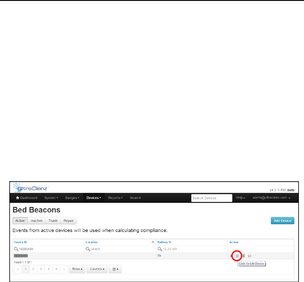
The metadata can only be accessed by restricted logins. Read the Bed Beacon address on the product label. The Bed
Beacon hexadecimal address will start with a 1E. The 1E at the beginning of the address is the device type and tells the
dashboard that this is a Bed Beacon. Enter the full address into the “Device ID” column search window. In the example
below, the address is 1E00048A (see Figure 19). Click the “Click To Edit Device” icon under the “Action” column to open
the device’s metadata page.
Figure 19. Active Bed Beacon List
Device Information (see Figure 19)
The Bed Beacon device information is optional. The device information can be found on the product label.
Facility (see Figure 14)
Select the facility location from the drop down list. The facility location is pre-populated in the “System” tab,
“Facility Setup” before the installation.
The box below the facility setup is used to enter the building metadata for large hospitals with multiple buildings
or wings. For single building hospitals this field can be left blank.
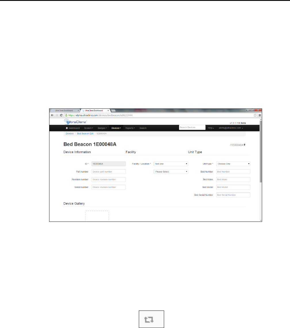
Unit Type (see Figure 20)
Unit type: Bed Beacon (not optional metadata). The unit types are pre-populated in the “System” tab, “Unit Types
Management”.
Patient Safeguard System® Patient Bed Installation
UltraClenz, LLC
Page 17
Bed Number: example – “001” (optional metadata). The installer can choose to place a numbered label at the
bed’s footboard frame to easily identify beds because the Bed Beacon label may not be in a convenient location to
easily view.
Bed Make: example – “Hill Rom” (optional metadata). The bed manufacturer information can assist staff in
identifying a bed.
Bed Model: example – “Versacare” (optional metadata). The bed model information can assist staff in identifying a
bed.
Bed Serial Number: example – “123456” (optional metadata). The bed serial number information can assist staff in
identifying a bed.
Figure 20. Bed Beacon Metadata
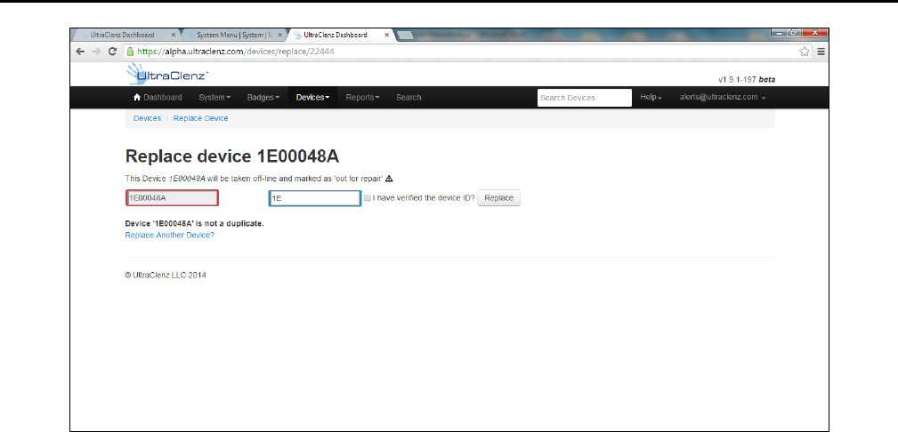
6.2 Replacing an Existing Bed Beacon – Swapping Metadata
Remove the Bed Beacon and read the address from the product label. Enter the Bed Beacon’s address in the active
Bed Beacon device list (see Figure 19 above). Click the replace icon in the device list “Action” column (see Figure 19).
The replacement tab will open. Enter the new Bed Beacon’s address into the blue box. Check the “I have verified the
device ID” then click “Replace” to transfer the old Bed Beacon’s red box to the new Bed Beacon blue box (see Figure
22). The old Bed Beacon will be marked for repair and deleted from the active device list. Click “Replace Another
Device?” to replace another Bed Beacon.
Figure 21. Replace Icon
Patient Safeguard System® Patient Bed Installation
UltraClenz, LLC
Page 18
Figure 22. Replace Device Tab
7. Troubleshooting
7.1 No Bed Beacon Heartbeats on the Dashboard
If the Bed Beacon has stopped transmitting heartbeats to the Dashboard there is one of three possible solutions:
1. The batteries have died. Place a new set of batteries in the Bed Beacon and test the Bed Beacon’s other
function, communications with a Badge as described in section 5. If the unit tests well, then give the Bed
Beacon a couple of hours to transmit a few heartbeats to the Dashboard.
2. If new batteries do not fix the problem, there is a problem with the wireless network hardware. Remove and
replace the Bed Beacon. Refer to section 6.2 – Replacing an Existing Bed Beacon – Swapping Metadata for
instructions on how to replace device information on the dashboard.
3. If replacing the Bed Beacon does not remedy the problem there, may be a problem with the Bentley network.
7.2 The Bed Installation Does Not Communicate with a Badge
If a Bed Installation is not communicating with Badges but is sending heartbeats to the dashboard, there are a number
of possible causes. The following steps will help to find the cause of the problem.
7.3 Bed Beacon FAS1541
1. Verify that the bed’s AC power cord is plugged into an active power source and the ALP Sensor is connected to
the Bed Beacon. Verify that you get an alert and a red flash when disconnecting from the Bed Beacon.
2. Verify the batteries of the Bed Beacon are 2.20v or Higher.
Note: If any of the components of the Bed Installation are replaced, the bed’s range will have to be re-checked and
readjusted as needed.
Patient Safeguard System® Patient Bed Installation
UltraClenz, LLC
Page 19
8. System Component Care and Maintenance
8.1 Cleaning the Components
The components should be cleaned by wiping with a soft cloth. The cloth should be damp but not wet. A soft cloth
dampened with isopropyl alcohol works well to clean the external surfaces. Only the exterior of the components may
be cleaned. Do not attempt to clean any interior surface of these components as this will damage the component’s
circuitry. Do not use abrasive cleaners or cleaning products in aerosol cans as they will damage the component’s finish.
8.2 Handling the Bed Beacon
The Bed Beacon is an electronic device and should be handled with care. Like other electronic devices such as cell
phones, the Bed Beacon must be protected from extreme heat, cold and moisture. Avoid handling the Bed Beacon
with wet hands or exposing it to rain. Avoid dropping or tossing the Bed Beacon. The shock can damage the Beacon’s
sensitive internal electronics.
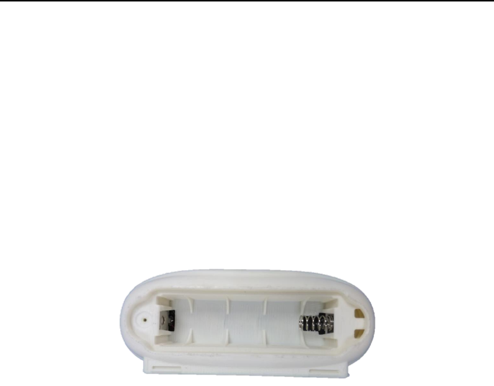
8.3 Battery Replacement
Bed Beacon is powered by 2 “D” Cell Alkaline Batteries. Avoid reverse polarity by installing the batteries as indicated.
Figure 23. Battery Cover
Patient Safeguard System® Patient Bed Installation
UltraClenz, LLC
Page 20
Appendix A - Certification and Safety Approvals
FCC Statement
NOTE: This equipment has been tested and found to comply with the limits for a Class B digital device, pursuant to Part 15 of the FCC
Rules. These limits are designed to provide reasonable protection against harmful interference in a residential installation. This
equipment generates, uses, and can radiate radio frequency energy and, if not installed and used in accordance with the instructions,
may cause harmful interference to radio communications. However, there is no guarantee that interference will not occur in a
particular installation. If this equipment causes harmful interference to radio or television reception, which can be determined by
turning the equipment off and on, the user is encouraged to try and correct the interference by one or more of the following
measures:
Reorient or relocate the receiving antenna.
Increase the separation between the equipment and receiver.
Connect the equipment into an outlet on a circuit different from that to which the receiver is connected.
Consult the dealer or an experienced radio/TV technician for help.
WARNING: Changes or modifications not expressly approved by UltraClenz, LLC could void the user’s authority to operate the
equipment.
RF EXPOSURE:
“This equipment complies with FCC radiation exposure limits set forth for an uncontrolled environment. This equipment should be
installed and operated with minimum distance 20cm between the radiator and your body. This transmitter must not be co-located or
operating in conjunction with any other antenna or transmitter.”
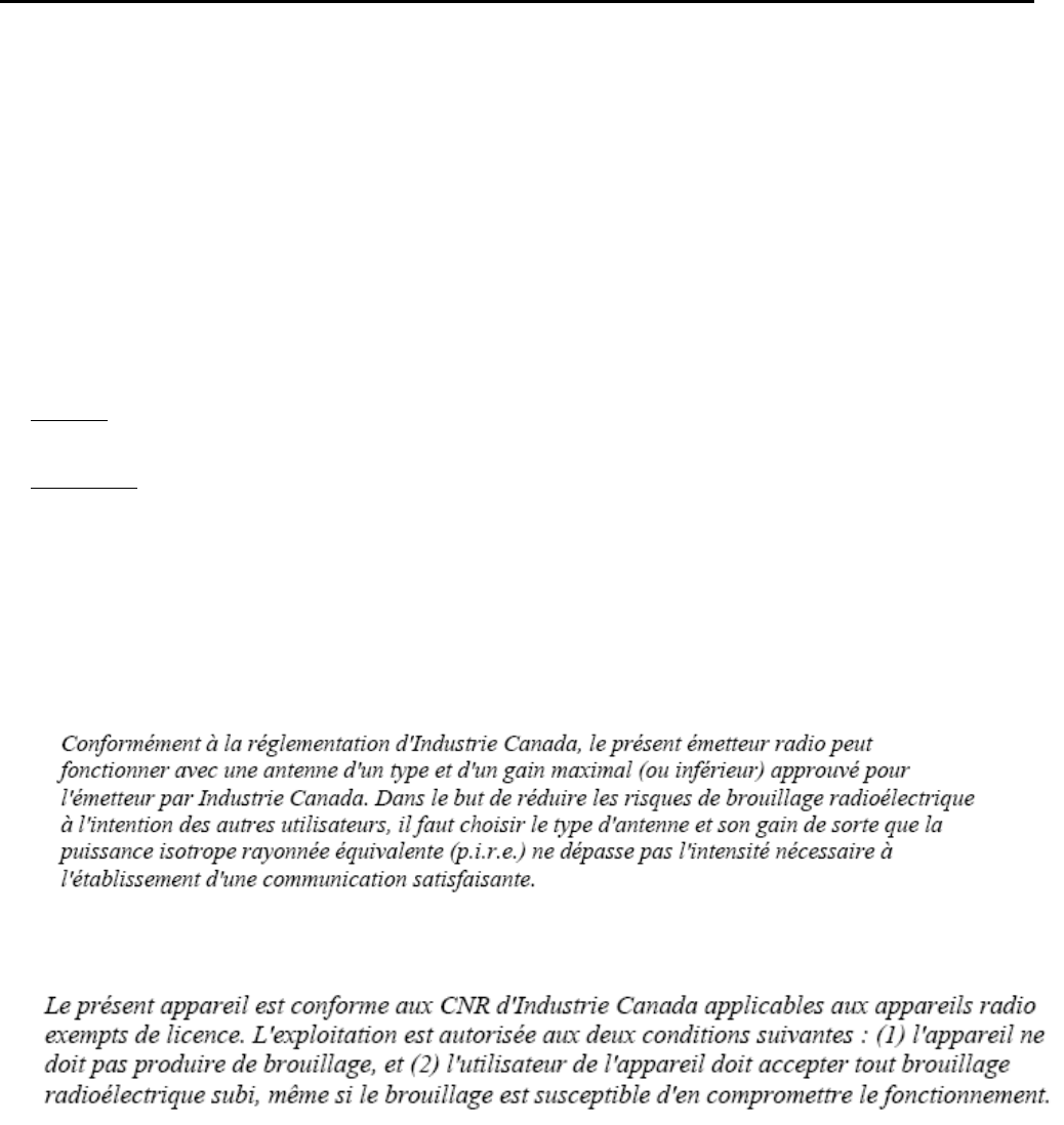
Industry Canada
Under Industry Canada regulations, this radio transmitter may only operate using an antenna of a type and maximum (or lesser) gain
approved for the transmitter by Industry Canada. To reduce potential radio interference to other users, the antenna type and its gain
should be so chosen that the equivalent isotropically radiated power (e.i.r.p.) is not more than that necessary for successful
communication.
This device complies with Industry Canada license-exempt RSS standard(s). Operation is subject to the following two conditions: (1)
this device may not cause interference, and (2) this device must accept any interference, including interference that may cause
undesired operation of the device.
This radio transmitter (IC:10060A-FAS1541) has been approved by Industry Canada to operate with the antenna types listed below
with the maximum permissible gain and required antenna impedance for each antenna type indicated. Antenna types not included in
this list, having a gain greater than the maximum gain indicated for that type, are strictly prohibited for use with this device.
Le présent émetteur radio (IC:10060A-FAS1541) a été approuvé par Industrie Canada pour fonctionner avec les
types d'antenne énumérés ci-dessous et ayant un gain admissible maximal et l'impédance requise pour chaque type d'antenne. Les
types d'antenne non inclus dans cette liste, ou dont le gain est supérieur au gain maximal indiqué, sont strictement interdits pour
l'exploitation de l'émetteur.

Patient Safeguard System® Patient Bed Installation
UltraClenz, LLC
Page 21
Appendix B - Warranty
This device is warranted against defective materials and workmanship for two years from the date of purchase.
Equipment covered by this warranty will be repaired or replaced in the United States and Canada, WITHOUT CHARGE,
except for shipping and handling, by our Factory Service Center.
When returning equipment for warranty service, you must first call your distributor’s Warranty Service Department for
your Return Merchandise Authorization Number (RMA). The RMA must be on your return label and the shipping charges
must be pre-paid and a copy of your receipt must be enclosed. Equipment should be returned to UltraClenz Customer
Service, 1201 Jupiter Park Drive, Jupiter, FL 33458.
This warranty covers all defects incurred from normal use of the equipment and does not apply in the following cases:
a. Loss or damage to the equipment due to abuse, mishandling, accident or failure to follow installation or use
instructions.
b. If the equipment is defective as a result of leaking batteries.
c. If the equipment has been serviced or modified by someone other than our authorized agents.
THE AFOREMENTIONED IS IN LIEU OF ALL WARRANTIES, EXPRESSED OR IMPLIED, INCLUDING BUT NOT LIMITED TO, ANY
WARRANTY OF MERCHANTABILITY OR OF FITNESS FOR ANY PARTICULAR PURPOSE. IN NO EVENT SHALL THE VENDOR BE
LIABLE FOR CONSEQUENTIAL, INCIDENTAL, INDIRECT OR SPECIAL DAMAGES OR LIABILITY, TRANSPORTATION,
INSTALLATION OR SUBSTITUTION COSTS, DELAYS, OR FOR ANY OTHER DAMAGES, COSTS, OR EXPENSES INCURRED,
IRRESPECTIVE OF HOW THEY OCCUR. THIS WARRANTY SHALL NOT EXTEND TO ANY OTHER PERSON OTHER THAN THE
ORIGINAL PUCHASER OF THIS EQUIPMENT OR THE PERSON FOR WHOM IT WAS PURCHASED AS A GIFT.
This warranty gives you specific legal rights, and you may also have other rights, which may vary from state to state. This
warranty is given with respect to equipment purchased in the United States.
Patient Safeguard System® Patient Bed Installation
UltraClenz, LLC
Page 22
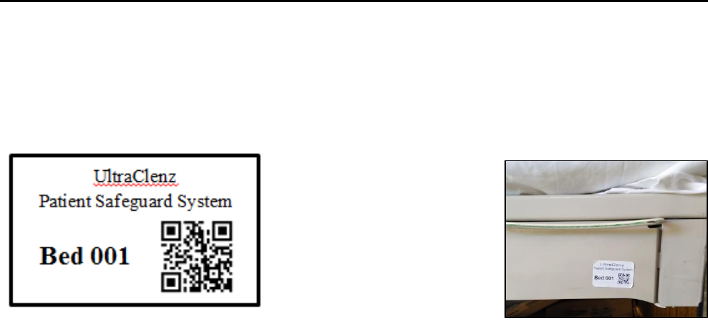
Appendix C – Bed Label
The bed label (Figure 1) is a unique bed number that will be linked to the PSS dashboard Bed Beacon Metadata. During
installation, the bed labels are located on or near the foot-board frame of the patient bed (Figure 2). The bed number helps
to quickly identify the PSS Bed Beacon address that’s on the bed.
Figure 1. Bed Installation Label
Figure 2. Bed Label Location