Edgecore Networks ECW7210L IEEE 802.11a/b/g/n/ac Enterprise Cloud Based Indoor Access Point User Manual Quick Start Guide
Edgecore Networks Corporation IEEE 802.11a/b/g/n/ac Enterprise Cloud Based Indoor Access Point Quick Start Guide
Contents
- 1. User Manual-1
- 2. User Manual-2
User Manual-1
– 1 –
Quick Start Guide
IEEE 802.11a/b/g/n/ac Enterprise Cloud Based Indoor Access Point
ECW7210-L
Note:
For detailed access point (AP) installation information, refer to the
Installation Guide, which is on the Documentation CD included with the AP.
Note:
For Safety and Regulatory information, refer to the Safety and Regulatory
Information document included with the AP.
Installation Information
The AP includes its own built-in features for mounting the unit to a wall or
suspended ceiling T-rail.
Caution:
The planning and installation of the AP requires professional personnel
that are trained in the installation of radio transmitting equipment. The user is
responsible for compliance with local regulations concerning items such as
antenna power, use of lightning arrestors, grounding, and radio mast or tower
construction. Therefore, it is recommended to consult a professional contractor
knowledgeable in local radio regulations prior to equipment installation.
Follow these steps to install the AP:
1. Unpack the AP Unpack the AP and check the package contents.
◆ECW7210-L Enterprise Access Point
◆AC Power adapter
◆Console cable (RJ-45 to DB-9)
◆Quick Start Guide (this guide)
◆Regulatory and Safety Information
◆Screw Kit
150200000848A
E032014-AP-R01
www.edge-core.com
Quick Start Guide
– 2 –
2. Mount the AP After planning your installation, mount the unit on a wall or suspended ceiling
T-rail.
.
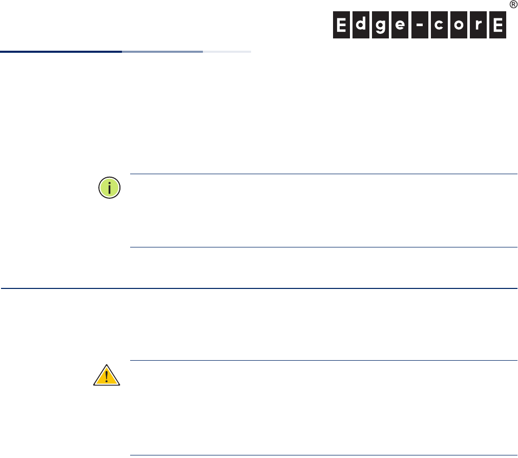
Mounting on a Wall
Set two screws in the wall 137.2 mm (5.2 in.) apart.
Slide the AP’s wall mounting slots down onto the screws so that the unit is secure.
1
2
1
2
1
2
.
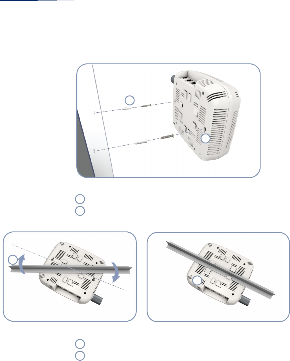
Mounting on a Ceiling T-rail
Position the AP’s ceiling-mount clip holders on either side of the T-rail.
Turn the AP until the two clips lock the AP to the T-rail.
1
2
Quick Start Guide
– 3 –
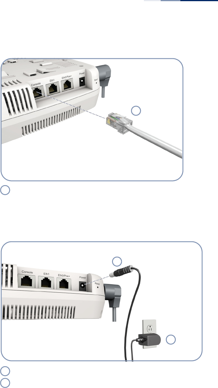
3. Connect Cables Connect network cable to the RJ-45 port for your network connection. The RJ-45
port connection can also provide PoE power to the unit.
4. Connect Power If you do not power the unit using PoE, connect the AC power adapter to the AP
and to an AC power source.
Connect Category 5e or better cable to the RJ-45 port.
1
1
Connect the power adapter to the power socket.
Connect the power adapter to a nearby AC power source.
1
2
1
2
Quick Start Guide
– 4 –
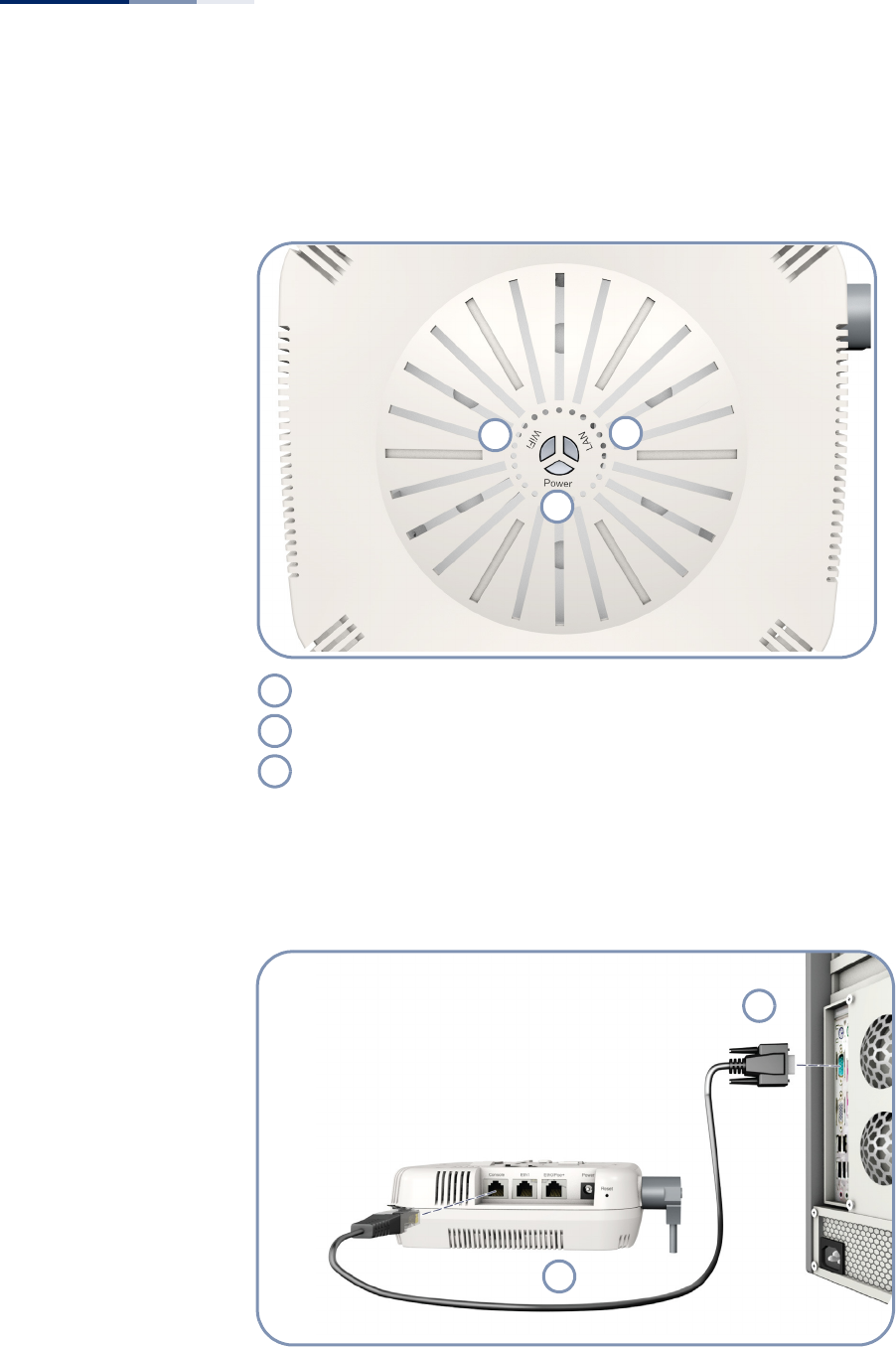
5. Verify AP Operation Verify basic AP operation by checking the system LEDs.
The Power LED should be on green and the LAN LED on or flashing green.
6. Connect to the
Console Port
To make initial configuration changes to the AP, connect a PC to the AP’s console
port using the included console cable.
WiFi
Power
LAN
2
13
1
2
3
1
2

Quick Start Guide
– 5 –
From a PC running VT-100 terminal emulator software, use the following settings:
◆Baud rate — 115,200 bps
◆Character Size — 8 Characters
◆Parity — None
◆Stop bit — One
◆Data bits — 8
◆Flow control — none
Log in to the command-line interface (CLI) using default settings:
◆Login Name — admin
◆Password — null (there is no default password)
7. Connect to the Web
User Interface
The AP offers a user-friendly web-based management interface for the
configuration of all the unit’s features.
You can make initial configuration changes by connecting a PC directly to the AP’s
LAN port. The AP has a default management IP address of 192.168.1.10 and a
subnet mask of 255.255.255.0. You must set your PC IP address to be on the same
subnet as the AP (that is, the PC and AP addresses must both start 192.168.1.x).
Log in to the web interface using the default settings:
◆Login Name — admin
◆Password — tallacnetworks
Console Port
Console Cable
1
2
Quick Start Guide
– 6 –
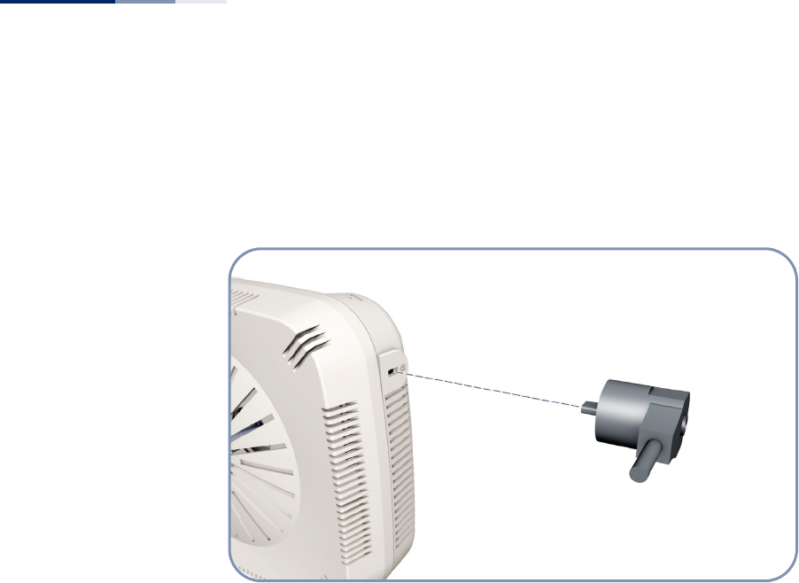
8. Security Slot The access point includes a Kensington security slot on the rear panel. You can
prevent unauthorized removal of the access point by wrapping the Kensington
security cable (not provided) around an unmovable object, inserting the lock into
the slot, and turning the key.

Quick Start Guide
– 7 –
Hardware Specifications
Item Specification
Chassis Specifications
Size W x D x H: 180 x 160 x 53 mm (7.08 x 6.29 x 2.08 inches)
Weight 638 g (1.40 lb)
Temperature Operating: 0 °C to 40 °C (32 °F to 104 °F)
Storage: -20 °C to 70 °C (-4 °F to 158 °F)
Humidity Operating: 5% to 95% (non-condensing)
Network Interfaces
Ports Two RJ45 1000Base-T: One with PoE (PD)
2.4 GHz Radio IEEE 802.11b/g/n
5 GHz Radio IEEE 802.11a/n/ac
Radio Frequencies
2.4 GHz 2400 ~ 2483.5 MHz
5 GHz B1: 5150 ~ 5250 MHz
B4: 5725 ~ 5850 MHz
Power Supply Specifications
PoE Input Power 48 VDC, 0.6 A
AC Power Adapter AC Input: 100 ~ 240 VAC, 50 ~ 60 Hz
DC Output: 12 VDC, 2.5 A
Power Consumption 20 W maximum
Regulatory Compliances
Radio FCC Part 15C 15.247/15.207 (2.4-2.4835GHz, 5.725-5.850GHz)
FCC Part 15E 15.407 (5.150GHz-5.250GHz)
Emissions FCC Class B Part 15
Safety UL 60950-1