Edgecore Networks SMC2891WAN 802.11a/b/g/n Outdoor Dual Band Wireless Access Point User Manual user guide
Edgecore Networks Corporation 802.11a/b/g/n Outdoor Dual Band Wireless Access Point user guide
Contents
- 1. User Manual - IG
- 2. User Manual - MG
- 3. User Manual - QSG
- 4. User Manual - Statements
User Manual - MG


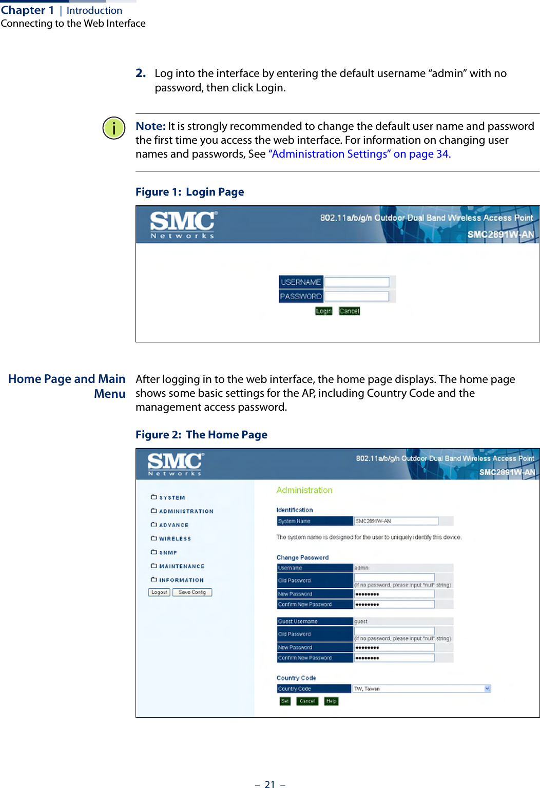
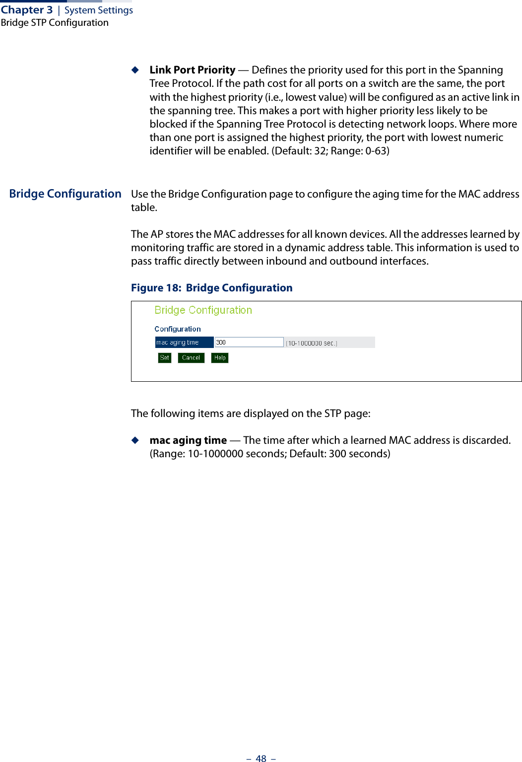
![Chapter 1 | IntroductionNetwork Connections– 20 –2. At the login prompt, enter “admin.”3. At the Password prompt, press <Enter>. There is no default password. 4. The session is opened and the CLI displays the “Accton#” prompt indicating you have access to the CLI commands. Example(none) login: adminPassword:Jan 1 11:33:13 login[1918]: root login on 'ttyS0'SMC#Network ConnectionsPrior to accessing the AP’s management agent through a network connection, you must first configure it with a valid IP address, subnet mask, and default gateway using a console connection, or the DHCP protocol.The AP has a static default management IPv4 address of 192.168.1.10 and a subnet mask of 255.255.255.0. Once the AP’s IP settings are configured for the network, you can access the AP’s management agent from anywhere within the attached network. The management agent can be accessed using Telnet from any computer attached to the network. The AP can also be managed by any computer using a web browser, or from a network computer using SNMP network management software.Connecting to the Web InterfaceThe AP offers a user-friendly web-based management interface for the configuration of all the unit’s features. Any PC directly attached to the unit can access the management interface using a web browser, such as Internet Explorer (version 6.x or above) or Firefox (version 2.x or above).You may want to make initial configuration changes by connecting a PC directly to the AP’s LAN port. The AP has a default management IP address of 192.168.1.10 and a subnet mask of 255.255.255.0. You must set your PC IP address to be on the same subnet as the AP (that is, the PC and AP addresses must both start 192.168.1.x).To access the AP’s web management interface, follow these steps:1. Use your web browser to connect to the management interface using the default IP address of 192.168.1.10.](https://usermanual.wiki/Edgecore-Networks/SMC2891WAN.User-Manual-MG/User-Guide-1903199-Page-20.png)
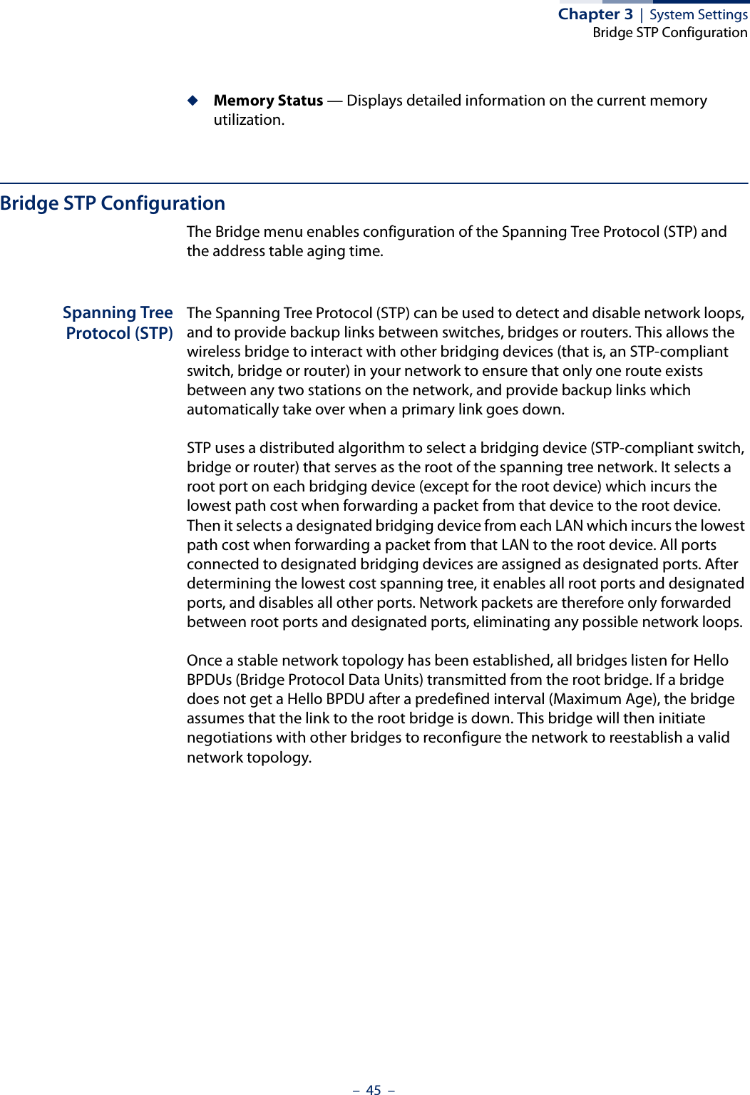
![Chapter 3 | System SettingsBridge STP Configuration– 47 –to the network. (Default: 20 seconds; Range: 6-40 seconds)Minimum: The higher of 6 or [2 x (Hello Time + 1)].Maximum: The lower of 40 or [2 x (Forward Delay - 1)]◆Hello Time — Interval (in seconds) at which the root device transmits a configuration message. (Default: 2 seconds; Range: 1-10 seconds)Minimum: 1Maximum: The lower of 10 or [(Max. Message Age / 2) -1]◆Forwarding Delay — The maximum time (in seconds) this device waits before changing states (i.e., discarding to learning to forwarding). This delay is required because every device must receive information about topology changes before it starts to forward frames. In addition, each port needs time to listen for conflicting information that would make it return to a discarding state; otherwise, temporary data loops might result. (Default: 15 seconds; Range: 1-30 seconds)Minimum: The higher of 1 or [(Max. Message Age / 2) + 1]Maximum: 30Ethernet InterfaceSets STP settings for the Ethernet port.◆Link Path Cost — This parameter is used by the STP to determine the best path between devices. Therefore, lower values should be assigned to ports attached to faster media, and higher values assigned to ports with slower media. (Path cost takes precedence over port priority.) (Default: 4; Range: 1-65535)◆Link Port Priority — Defines the priority used for this port in the Spanning Tree Protocol. If the path cost for all ports on a switch are the same, the port with the highest priority (i.e., lowest value) will be configured as an active link in the spanning tree. This makes a port with higher priority less likely to be blocked if the Spanning Tree Protocol is detecting network loops. Where more than one port is assigned the highest priority, the port with lowest numeric identifier will be enabled. (Default: 32; Range: 0-63)Wireless InterfaceSets STP settings for the radio interface.◆Index — Describes the VAP in question.◆Link Path Cost — This parameter is used by the STP to determine the best path between devices. Therefore, lower values should be assigned to ports attached to faster media, and higher values assigned to ports with slower media. (Path cost takes precedence over port priority.) (Default: 19; Range: 1-65535.)](https://usermanual.wiki/Edgecore-Networks/SMC2891WAN.User-Manual-MG/User-Guide-1903199-Page-47.png)
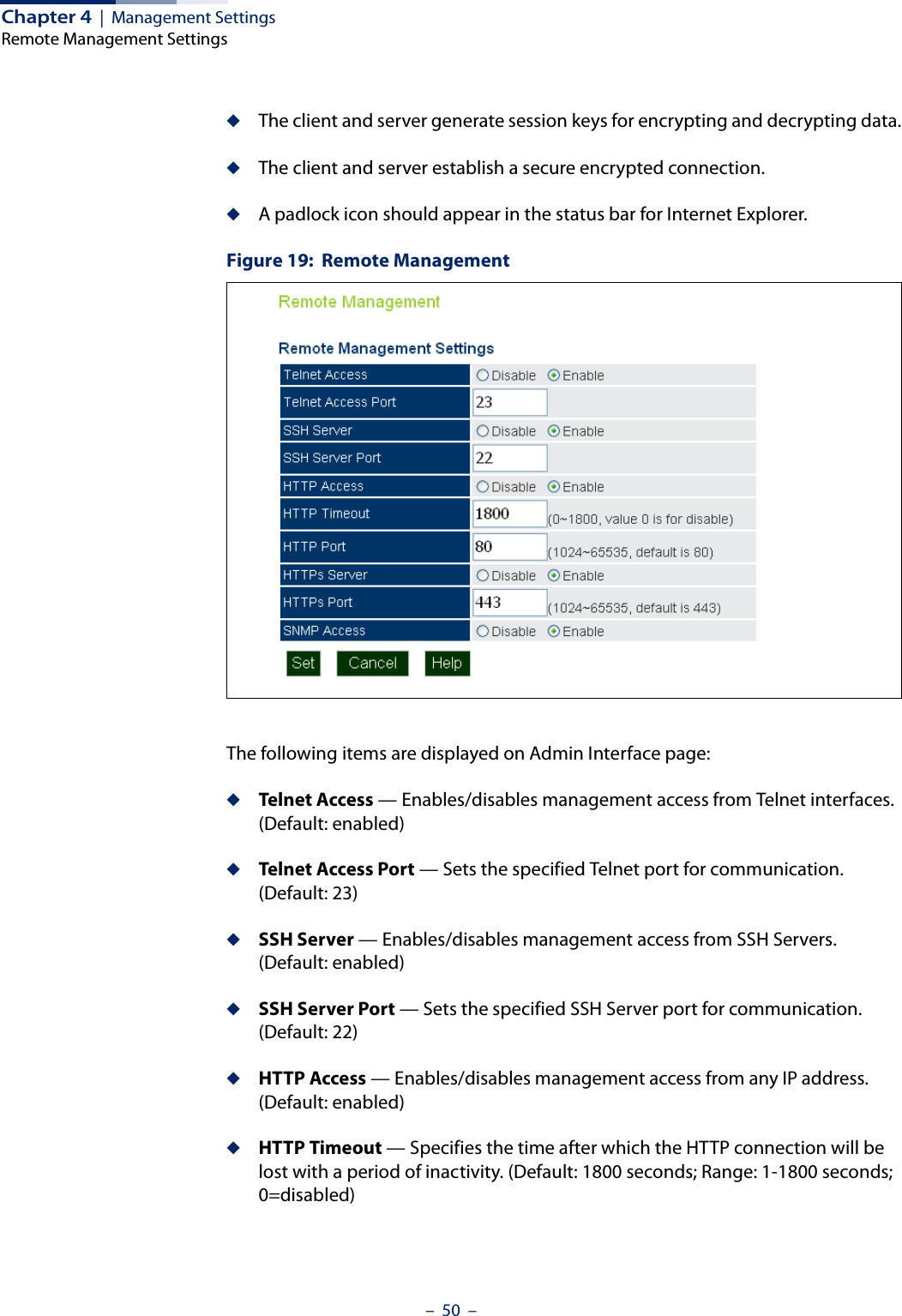
![– 49 –4Management SettingsThis chapter describes management access settings on the access point. It includes the following sections:◆“Remote Management Settings” on page 49◆“Access Limitation” on page 51◆“Simple Network Management Protocol” on page 52Remote Management SettingsThe Web, Telnet, and SNMP management interfaces are enabled and open to all IP addresses by default. To provide more security for management access to the access point, specific interfaces can be disabled and management restricted to a single IP address or a limited range of IP addresses.Once you specify an IP address or range of addresses, access to management interfaces is restricted to the specified addresses. If anyone tries to access a management interface from an unauthorized address, the access point will reject the connection.Telnet is a remote management tool that can be used to configure the access point from anywhere in the network. However, Telnet is not secure from hostile attacks. The Secure Shell (SSH) can act as a secure replacement for Telnet. The SSH protocol uses generated public keys to encrypt all data transfers passing between the access point and SSH-enabled management station clients and ensures that data traveling over the network arrives unaltered. Clients can then securely use the local user name and password for access authentication.Note that SSH client software needs to be installed on the management station to access the access point for management via the SSH protocol.Both HTTP and HTTPS service can be enabled independently. If you enable HTTPS, you must indicate this in the URL: https://device:port_number]When you start HTTPS, the connection is established in this way:◆The client authenticates the server using the server’s digital certificate.◆The client and server negotiate a set of security protocols to use for the connection.](https://usermanual.wiki/Edgecore-Networks/SMC2891WAN.User-Manual-MG/User-Guide-1903199-Page-49.png)
![– 109 –9Using the Command Line InterfaceWhen accessing the management interface for the over a direct connection to the console port, or via a Telnet connection, the access point can be managed by entering command keywords and parameters at the prompt. Using the access point’s command-line interface (CLI) is very similar to entering commands on a UNIX system.Console ConnectionTo access the AP through the console port, first set up a console connection to the AP. See “Console Port Connection” on page 19 for more information.At the console prompt, enter the user name and password. (The default user name is “admin” with no default password.) After the password is entered, the CLI displays the “SMC#” prompt. Example(none) login: adminPassword:Jan 1 11:33:13 login[1918]: root login on 'ttyS0'SMC#Note: Command examples shown later in this chapter abbreviate the console prompt to “AP” for simplicity.Enter the necessary commands to complete your desired tasks. When finished, exit the session with the “exit” command.](https://usermanual.wiki/Edgecore-Networks/SMC2891WAN.User-Manual-MG/User-Guide-1903199-Page-109.png)
![Chapter 9 | Using the Command Line InterfaceEntering Commands– 113 –current mode. The command classes and associated modes are displayed in the following table:Exec CommandsWhen you open a new console session on an access point, the system enters Exec command mode. Only a limited number of the commands are available in this mode. You can access all other commands only from the configuration mode. To access Exec mode, open a new console session with the user name “admin.” The command prompt displays as “AP#” for Exec mode.(none) login: adminPassword: [system login password]AP#Configuration CommandsConfiguration commands are used to modify access point settings. These commands modify the running configuration and are saved in memory. The configuration commands are organized into four different modes:◆Global Configuration (GC) - These commands modify the system level configuration, and include commands such as system name and password. ◆Interface-Ethernet Configuration (IC-E) - These commands modify the Ethernet port configuration, and include command such as dns and ip.◆Interface-Wireless Configuration (IC-W) - These commands modify the wireless port configuration of global parameters for the radio, and include commands such as channel and beacon-interval.◆Interface-Wireless Virtual Access Point Configuration (IC-W-VAP) - These commands modify the wireless port configuration for each VAP, and include commands such as ssid and encryption.To enter the Global Configuration mode, enter the command configure in Exec mode. The system prompt will change to “AP(config)#” which gives you access privilege to all Global Configuration commands.Table 3: Command ModesClass ModeExec PrivilegedConfiguration GlobalInterface-ethernetInterface-wirelessInterface-wireless-vap](https://usermanual.wiki/Edgecore-Networks/SMC2891WAN.User-Manual-MG/User-Guide-1903199-Page-113.png)
![Chapter 11 | System Management Commands– 126 –Default Setting Interface enabledCommand Mode Global ConfigurationExampleAP(config)# apmgmtui telnet-server enableAP(config)#apmgmtui http port This command specifies the TCP port number used by the web browser interface. Use the no form to use the default port.Syntax apmgmtui http port <port-number>no apmgmtui http portport-number - The TCP port to be used by the browser interface. (Range: 80 or 1024-65535)Default Setting 80Command Mode Global ConfigurationExampleAP(config)# apmgmtui http port 769AP(config)Related Commandsapmgmtui http serverapmgmtui http server This command allows this device to be monitored or configured from a web browser. Use the no form to disable this function.Syntax [no] apmgmtui http serverDefault Setting Enabled](https://usermanual.wiki/Edgecore-Networks/SMC2891WAN.User-Manual-MG/User-Guide-1903199-Page-126.png)
![Chapter 11 | System Management Commands– 128 –Command Mode Global ConfigurationCommand Usage ◆You cannot configure the HTTP and HTTPS servers to use the same port.◆To avoid using common reserved TCP port numbers below 1024, the configurable range is restricted to 443 and between 1024 and 65535. ◆If you change the HTTPS port number, clients attempting to connect to the HTTPS server must specify the port number in the URL, in this format: https://device:port_numberExample AP(config)# apmgmtui https port 1234AP(config)#apmgmtui httpsserverUse this command to enable the secure hypertext transfer protocol (HTTPS) over the Secure Socket Layer (SSL), providing secure access (that is, an encrypted connection) to the access point’s web interface. Use the no form to disable this function.Syntax [no] apmgmtui https serverDefault Setting EnabledCommand Mode Global ConfigurationCommand Usage ◆Both HTTP and HTTPS service can be enabled independently.◆If you enable HTTPS, you must indicate this in the URL: https://device:port_number]◆When you start HTTPS, the connection is established in this way:■The client authenticates the server using the server’s digital certificate.■The client and server negotiate a set of security protocols to use for the connection.■The client and server generate session keys for encrypting and decrypting data.](https://usermanual.wiki/Edgecore-Networks/SMC2891WAN.User-Manual-MG/User-Guide-1903199-Page-128.png)
![Chapter 11 | System Management Commands– 129 –■The client and server establish a secure encrypted connection.A padlock icon should appear in the status bar for Internet Explorer.Example AP(config)# apmgmtui https serverAP(config)#apmgmtui snmp This command enables and disables SNMP management access to the AP.Syntaxapmgmtui snmp [enable | disable]enable - Enables SNMP management access.disable - Disables SNMP management access.Default SettingEnabledCommand ModeGlobal ConfigurationExampleAP(config)# apmgmtui snmp enableAP(config)#apmgmtip This command specifies the client IP addresses that are allowed management access to the access point through various protocols.Note: Secure Web (HTTPS) connections are not affected by the UI Management or IP Management settings.Syntaxapmgmtip [multiple <ip-address> <subnet-mask> | single <ip-address> | any] multiple - Adds IP addresses within a specifiable range to the SNMP, web and Telnet groups.single - Adds an IP address to the SNMP, web and Telnet groups.any - Allows any IP address access through SNMP, web and Telnet groups.ip-address - Adds IP addresses to the SNMP, web and Telnet groups.](https://usermanual.wiki/Edgecore-Networks/SMC2891WAN.User-Manual-MG/User-Guide-1903199-Page-129.png)
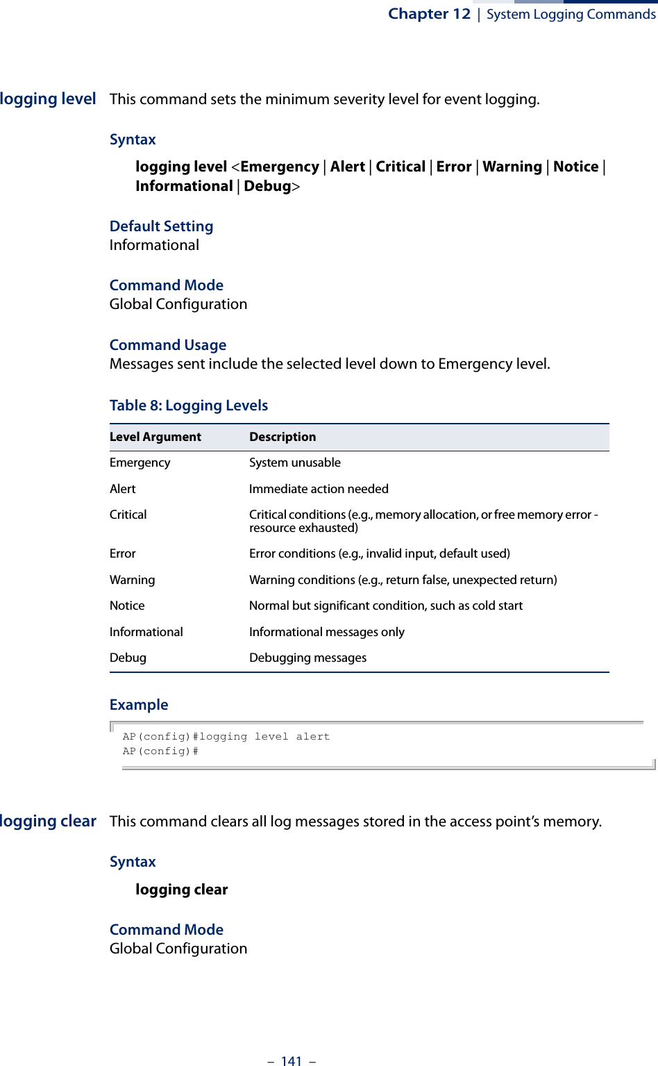
![– 139 –12 System Logging CommandsThese commands are used to configure system logging on the access point.logging on This command controls logging of error messages; i.e., sending debug or error messages to memory. The no form disables the logging process.Syntax[no] logging onDefault SettingDisabledCommand Mode Global ConfigurationCommand Usage The logging process controls error messages saved to memory. You can use the logging level command to control the type of error messages that are stored in memory. Example AP(config)#logging onAP(config)#Table 7: System Management CommandsCommand Function Mode Pagelogging on Controls logging of error messages GC 139logging host Adds a syslog server host IP address that will receive logging messages GC 140logging console Initiates logging of error messages to the console GC 140logging level Defines the minimum severity level for event logging GC 141logging clear Clears all log entries in access point memory GC 141show logging Displays the state of logging Exec 142show event-log Displays all log entries in access point memory Exec 142](https://usermanual.wiki/Edgecore-Networks/SMC2891WAN.User-Manual-MG/User-Guide-1903199-Page-139.png)
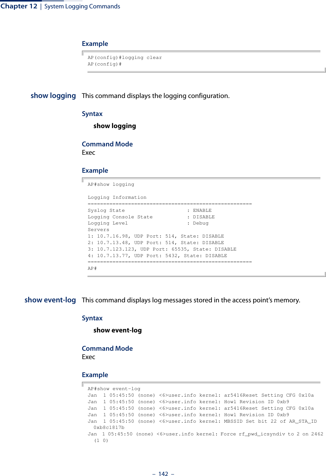
![Chapter 12 | System Logging Commands– 140 –logging host This command specifies syslog servers host that will receive logging messages. Use the no form to remove syslog server host.Syntaxlogging host <1 | 2 | 3 | 4> <host_name | host_ip_address> [udp_port]no logging host <1 | 2 | 3 | 4>1 - First syslog server.2 - Second syslog server.3 - Third syslog server.4 - Fourth syslog server.host_name - The name of a syslog server. (Range: 1-20 characters)host_ip_address - The IP address of a syslog server.udp_port - The UDP port used by the syslog server.Default Setting NoneCommand Mode Global ConfigurationExample AP(config)#logging host 1 10.1.0.3AP(config)#logging console This command initiates logging of error messages to the console. Use the no form to disable logging to the console.Syntax[no] logging consoleDefault Setting DisabledCommand Mode Global ConfigurationExample AP(config)#logging consoleAP(config)#](https://usermanual.wiki/Edgecore-Networks/SMC2891WAN.User-Manual-MG/User-Guide-1903199-Page-140.png)

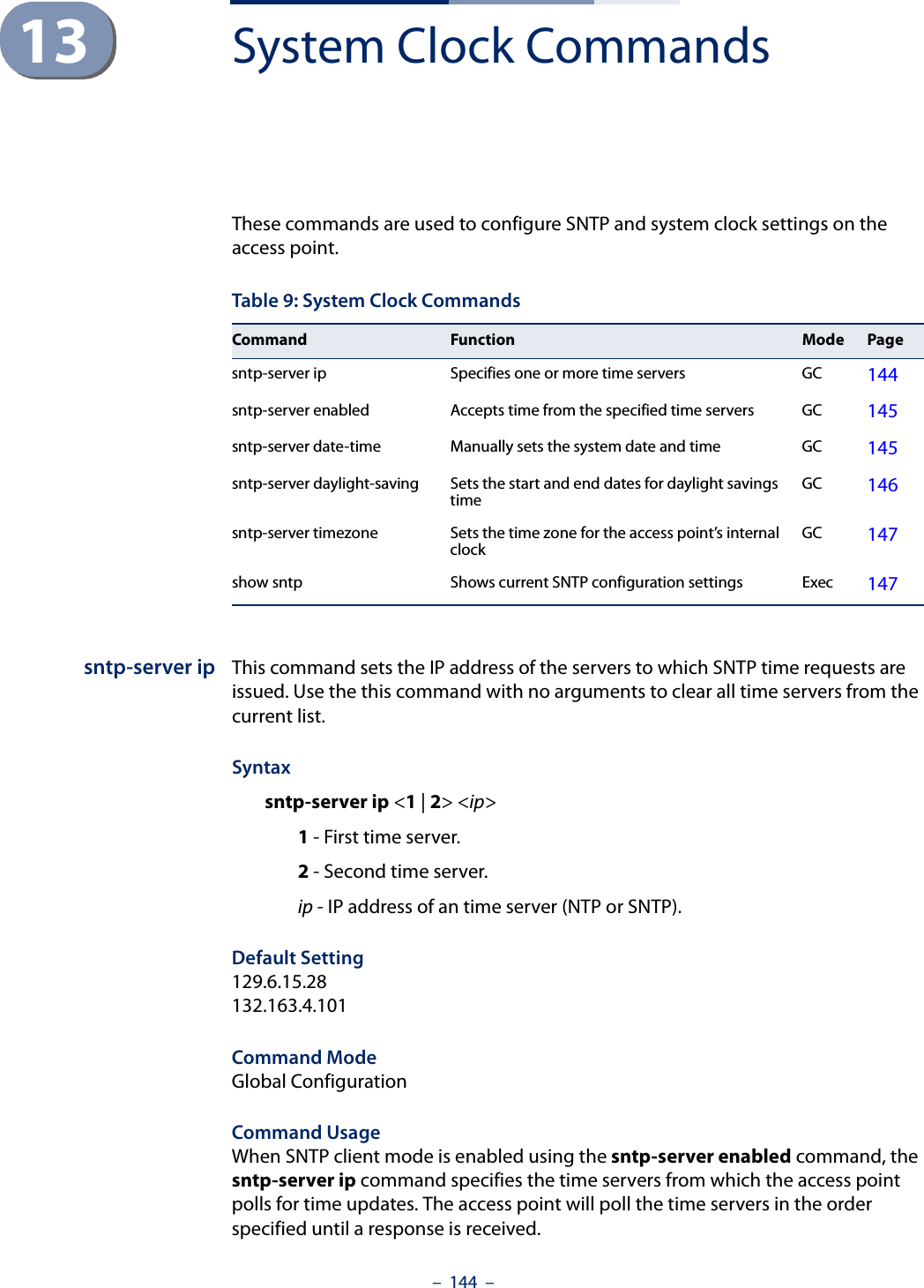
![Chapter 13 | System Clock Commands– 145 –Example AP(config)#sntp-server ip 1 10.1.0.19AP#Related Commandssntp-server enabledshow sntpsntp-server enabled This command enables SNTP client requests for time synchronization with NTP or SNTP time servers specified by the sntp-server ip command. Use the no form to disable SNTP client requests.Syntax[no] sntp-server enabledDefault Setting EnabledCommand Mode Global ConfigurationCommand Usage The time acquired from time servers is used to record accurate dates and times for log events. Without SNTP, the access point only records the time starting from the factory default set at the last bootup (i.e., 00:14:00, January 1, 1970).Example AP(config)#sntp-server enabledAP(config)#Related Commandssntp-server ipshow sntpsntp-server date-time This command sets the system clock.Syntaxsntp-server <year> <month> <day> <hour> <minute>year - Sets the year. (Range: 1970-2100)month - Sets the month. (Range: 1-12)day - Sets the day. (Range: 1-31)](https://usermanual.wiki/Edgecore-Networks/SMC2891WAN.User-Manual-MG/User-Guide-1903199-Page-145.png)
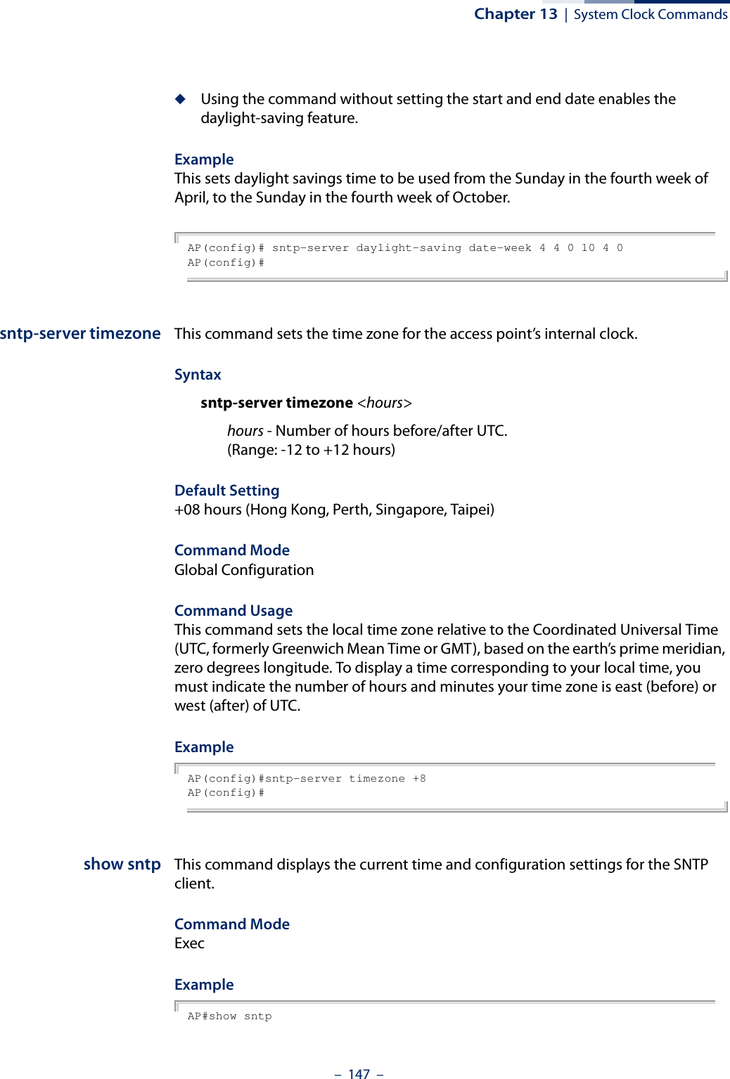
![Chapter 13 | System Clock Commands– 146 –hour - Sets the hour. (Range: 0-23)minute - Sets the minute. (Range: 0-59)Default Setting 00:14:00, January 1, 1970Command Mode Global ConfigurationExample This example sets the system clock to 12:10 April 27, 2009.AP(config)# sntp-server date-time 2009 4 27 12 10AP(config)#Related Commandssntp-server enabledsntp-server daylight-savingThis command sets the start and end dates for daylight savings time. Use the no form to disable daylight savings time.Syntaxsntp-server daylight-saving [date-week <start-month> <start-week> <start-day> <end-month> <end-week> <end-day>]no sntp-server daylight-saving date-week - The key word to set the date on which to start and end the daylight-saving time.start-month - Sets the start month. (Range: 1-12)start-week - Sets the start week. (Range: 1-5)start-day - Sets the start day. (Range: 0-6, where 0 is Sunday)end-month - Sets the end month. (Range: 1-12)end-week - Sets the end week. (Range: 1-5)end-day - Sets the end day. (Range: 0-6, where 0 is Sunday)Default Setting DisabledCommand Mode Global ConfigurationCommand Usage ◆The command sets the system clock back one hour during the specified period.](https://usermanual.wiki/Edgecore-Networks/SMC2891WAN.User-Manual-MG/User-Guide-1903199-Page-146.png)

![– 149 –14 DHCP Relay CommandsDynamic Host Configuration Protocol (DHCP) can dynamically allocate an IP address and other configuration information to network clients that broadcast a request. To receive the broadcast request, the DHCP server would normally have to be on the same subnet as the client. However, when the access point’s DHCP relay agent is enabled, received client requests can be forwarded directly by the access point to a known DHCP server on another subnet. Responses from the DHCP server are returned to the access point, which then broadcasts them back to clients.dhcp-relay server This command configures the DHCP server address and enables the DHCP relay agent.Syntaxdhcp-relay server <ip_address>ip_address - IP address of the DHCP server.Default Setting 0.0.0.0 (disabled)Command Mode Interface Configuration (Wireless-VAP)Command Usage ◆For the DHCP relay agent to function, the DHCP server IP address must be configured. The default IP address “0.0.0.0” disables the DHCP relay agent.◆To view the DHCP relay status, use the show interface wireless command.Example AP(if-wireless 0: VAP[0])# dhcp-relay server 192.168.1.10AP(if-wireless 0: VAP[0])#Table 10: DHCP Relay CommandsCommand Function Mode Pagedhcp-relay server Sets the DHCP server address and enables the DHCP relay agent IC-W-VAP 149](https://usermanual.wiki/Edgecore-Networks/SMC2891WAN.User-Manual-MG/User-Guide-1903199-Page-149.png)
![Chapter 15 | SNMP Commands– 152 –snmp-servercommunityThis command defines the community access string for the Simple Network Management Protocol. Use the no form to remove the specified community string.Syntaxsnmp-server community string [ro | rw]no snmp-server community stringstring - Community string that acts like a password and permits access to the SNMP protocol. (Maximum length: 23 characters, case sensitive)ro - Specifies read-only access. Authorized management stations are only able to retrieve MIB objects. rw - Specifies read/write access. Authorized management stations are able to both retrieve and modify MIB objects.Default Setting ◆public - Read-only access. Authorized management stations are only able to retrieve MIB objects.◆private - Read/write access. Authorized management stations are able to both retrieve and modify MIB objects.Command Mode Global ConfigurationCommand Usage If you enter a community string without the ro or rw option, the default is read only.Example AP(config)#snmp-server community alpha rwAP(config)#snmp-server contact This command sets the system contact string. Use the no form to remove the system contact information.Syntaxsnmp-server contact stringno snmp-server contactstring - String that describes the system contact. (Maximum length: 255 characters)Default Setting None](https://usermanual.wiki/Edgecore-Networks/SMC2891WAN.User-Manual-MG/User-Guide-1903199-Page-152.png)
![Chapter 15 | SNMP Commands– 153 –Command Mode Global ConfigurationExample AP(config)#snmp-server contact PaulAP(config)#Related Commandssnmp-server locationsnmp-server location This command sets the system location string. Use the no form to remove the location string.Syntaxsnmp-server location <text>no snmp-server locationtext - String that describes the system location. (Maximum length: 255 characters)Default Setting NoneCommand Mode Global ConfigurationExample AP(config)#snmp-server location WC-19AP(config)#Related Commandssnmp-server contactsnmp-server enableserverThis command enables SNMP management access and also enables this device to send SNMP traps (i.e., notifications). Use the no form to disable SNMP service and trap messages.Syntax [no] snmp-server enable serverDefault Setting Enabled](https://usermanual.wiki/Edgecore-Networks/SMC2891WAN.User-Manual-MG/User-Guide-1903199-Page-153.png)
![Chapter 15 | SNMP Commands– 155 –Example AP(config)#snmp-server host 1 10.1.19.23 batmanAP(config)#Related Commandssnmp-server enable serversnmp-server trap This command enables the access point to send specific SNMP traps (i.e., notifications). Use the no form to disable specific trap messages.Syntaxsnmp-server trap <trap>no snmp-server trap <trap>trap - One of the following SNMP trap messages:sysSystemDown - The access point is about to shutdown and reboot.sysSystemUp - The access point is up and running.Default Setting All traps enabledCommand Mode Global ConfigurationCommand Usage This command is used in conjunction with the snmp-server host and snmp-server enable server commands to enable SNMP notifications.Example AP(config)#no snmp-server trap syssystemupAP(config)#snmp-server vacmviewThis command configures SNMP v3 views. Use the no form to delete an SNMP v3 view or remove a subtree from a filter.Syntaxsnmp-server vacm view <name> [included | excluded] <subtree> [mask <mask>]no snmp-server vacm view <name> [included | excluded] <subtree>name - A user-defined name that identifies an SNMP v3 view. (Maximum length: 32 characters)](https://usermanual.wiki/Edgecore-Networks/SMC2891WAN.User-Manual-MG/User-Guide-1903199-Page-155.png)
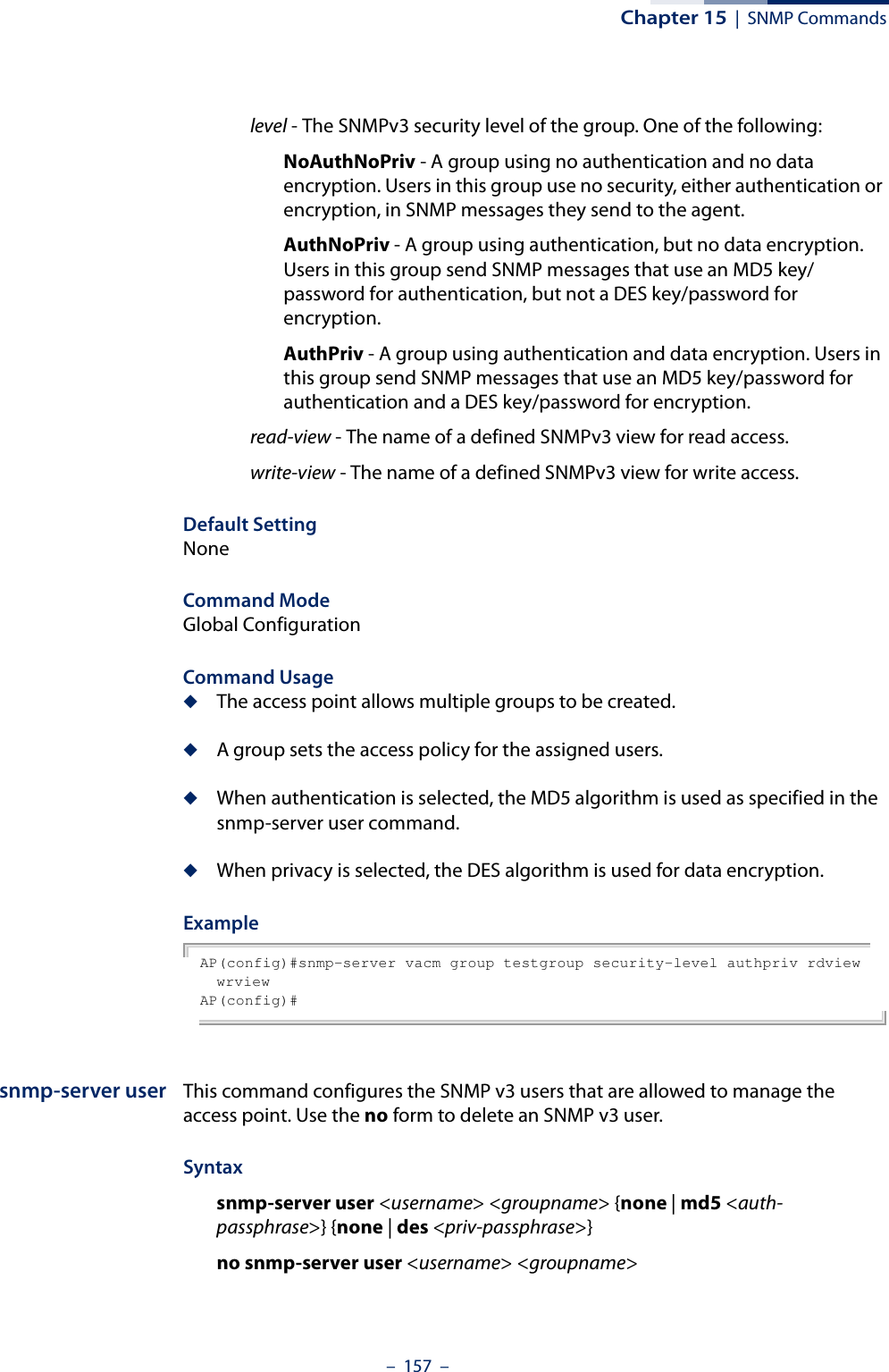
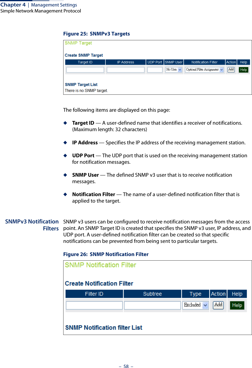
![Chapter 15 | SNMP Commands– 158 –username - Name of the user connecting to the SNMP agent. (Range: 1-32 characters)groupname - Name of an SNMP group to which the user is assigned. (Range: 1-32 characters)none | md5 - Uses no authentication or MD5 authentication.auth-passphrase - Authentication password. Enter a minimum of eight characters for the user. (8 – 32 characters)none | des - Uses SNMPv3 with no privacy, or with DES56 encryption.priv-passphrase - Privacy password. Enter a minimum of eight characters for the user. (8 – 32 characters)Default Setting NoneCommand Mode Global ConfigurationCommand Usage ◆Multiple SNMPv3 users can be configured on the access point.◆Users must be assigned to groups that have the same security levels. If a user who has “AuthPriv” security (uses authentication and encryption) is assigned to a NoAuthNoPriv group, the user will not be able to access the database. An AuthPriv user must be assigned to the group with the AuthPriv security level.Example AP(config)#snmp-server user chris grname md5 passw1 des passw2AP(config)#snmp-server target This command configures SNMP v3 notification targets. Use the no form to delete an SNMP v3 target.Syntaxsnmp-server target <target-id> <ip-addr> <sec-name> <port-number> [notification-filter-id]no snmp-server target <target-id>target-id - A user-defined name that identifies a receiver of SNMP notifications. (Maximum length: 32 characters)ip-addr - Specifies the IP address of the management station to receive notifications.sec-name - The defined SNMP v3 user name that is to receive notifications.](https://usermanual.wiki/Edgecore-Networks/SMC2891WAN.User-Manual-MG/User-Guide-1903199-Page-158.png)
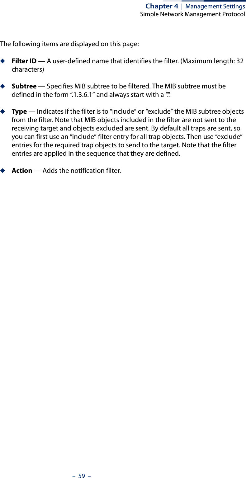
![Chapter 15 | SNMP Commands– 159 –port-number - The UDP port that is used on the receiving management station for notifications.notification-filter-id - The name if a defined notification filter.Default Setting NoneCommand Mode Global ConfigurationCommand Usage ◆The access point supports multiple SNMP v3 target IDs.◆The SNMP v3 user name that is specified in the target must first be configured using the snmp-server user command.Example AP(config)#snmp-server target tarname 192.168.1.33 chris 1234AP(config)#snmp-server filter This command configures SNMP v3 notification filters. Use the no form to delete an SNMP v3 filter or remove a subtree from a filter.Syntaxsnmp-server filter <filter-id> <include | exclude> <subtree> no snmp-server filter <filter-id> [subtree]filter-id - A user-defined name that identifies an SNMP v3 notification filter. (Maximum length: 32 characters)include - Defines a filter type that includes objects in the MIB subtree.exclude - Defines a filter type that excludes objects in the MIB subtree.subtree - The part of the MIB subtree that is to be filtered.Default Setting NoneCommand Mode Global ConfigurationCommand Usage ◆The access point allows multiple notification filters to be created. Each filter can be defined by up to 20 MIB subtree ID entries.](https://usermanual.wiki/Edgecore-Networks/SMC2891WAN.User-Manual-MG/User-Guide-1903199-Page-159.png)
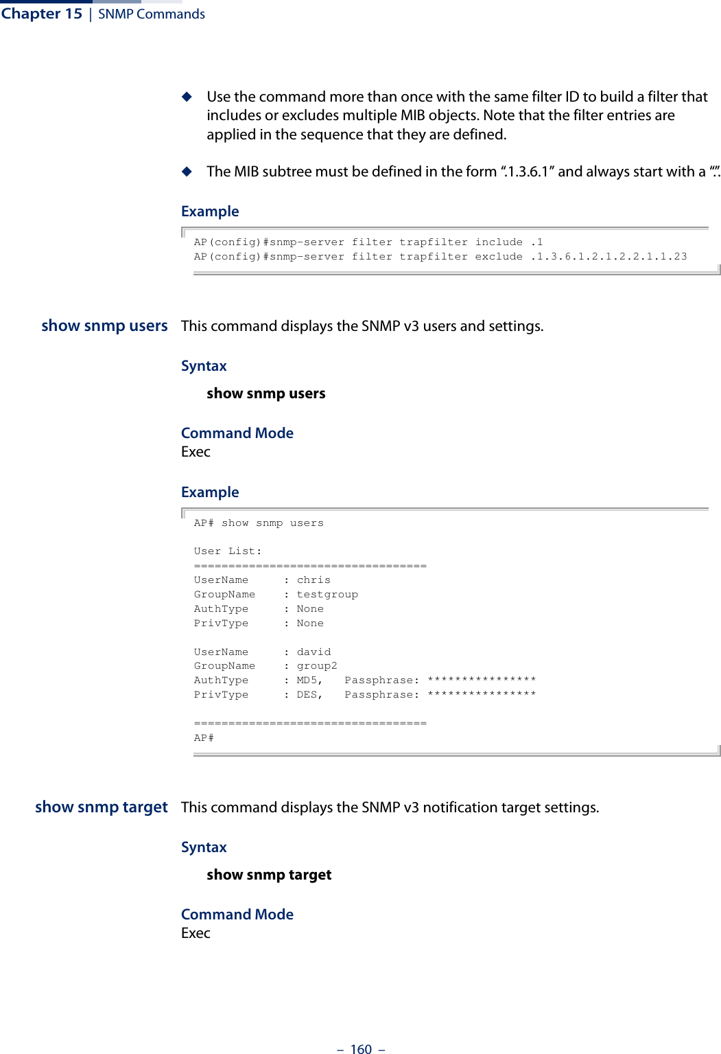
![Chapter 15 | SNMP Commands– 161 –Example AP# show snmp targetTarget List:==================================Target ID : christrapsIP Address : 192.168.1.33User Name : chrisUDP Port : 4321Filter ID : Not Defined==================================AP#show snmp filter This command displays the SNMP v3 notification filter settings.Syntaxshow snmp filter [filter-id] filter-id - A user-defined name that identifies an SNMP v3 notification filter. (Maximum length: 32 characters)Command Mode ExecExample AP# show snmp filterFilter List:==================================Filter: defaultfilter Type: Included Subtree: .1 Type: Excluded Subtree: .1.3.6.1.2.1.2.2.1.1.23Filter: testfilter Type: Excluded Subtree: .13.6.1.2.1.2.2.1.2==================================AP#show snmp This command displays the SNMP configuration settings.Command Mode Exec](https://usermanual.wiki/Edgecore-Networks/SMC2891WAN.User-Manual-MG/User-Guide-1903199-Page-161.png)
![Chapter 15 | SNMP Commands– 162 –ExampleAP# show snmpSNMP Information==============================================Service State : EnableCommunity (ro) : *******Community (rw) : ********Location : where?Contact : who?==============================================Trap Destination List:==============================================Trap Destination: 192.168.1.22, Community : *****==============================================Trap Configuration:========================================================================== systemUp: Disabled systemDown: Disabled==========================================================================AP#show snmp vacm view This command displays the configured SNMP v3 views.Syntaxshow snmp vacm view [view-name]view-name - The name of a user-defined SNMPv3 view. Command ModeExecExampleAP# sh snmp vacm viewView List:==================================View Name : defaultview Type : included OID : .1 Mask :View Name : testview Type : included OID : .1 Mask : Type : excluded OID : .13.6.1.2.1.2.2.1.2.1.1 Mask :==================================AP#](https://usermanual.wiki/Edgecore-Networks/SMC2891WAN.User-Manual-MG/User-Guide-1903199-Page-162.png)
![Chapter 15 | SNMP Commands– 163 –show snmp vacmgroupThis command displays the configured SNMP v3 groups.Syntaxshow snmp vacm group [group-name]group-name - The name of a user-defined SNMPv3 group.Command ModeExecExampleAP# sh snmp vacm groupGroup List:==================================Group Name : testgroupSecurity Level : NoAuthNoPrivRead-View : defaultviewWrite-View : defaultviewGroup Name : group2Security Level : AuthPrivRead-View : defaultviewWrite-View : defaultview==================================AP#](https://usermanual.wiki/Edgecore-Networks/SMC2891WAN.User-Manual-MG/User-Guide-1903199-Page-163.png)
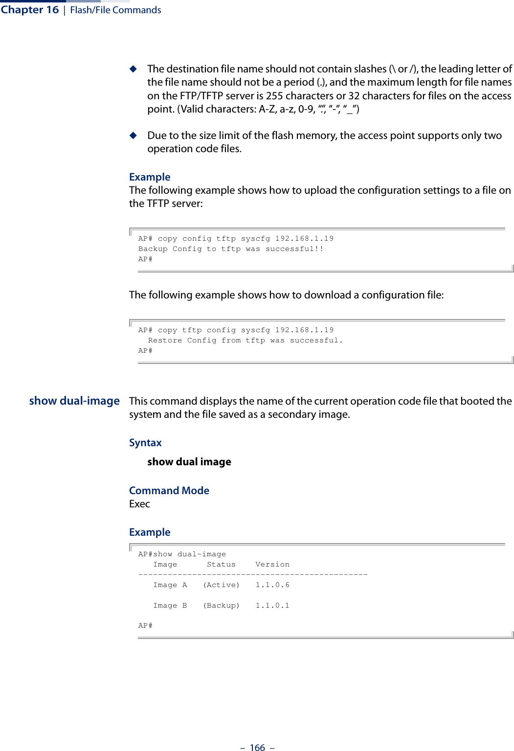
![– 164 –16 Flash/File CommandsThese commands are used to manage the system code or configuration files.dual-image This command specifies the image used to start up the system.Syntaxdual-image boot image [a | b]a - Selects image file A as the startup software.b - Selects image file B as the startup software.Default Setting NoneCommand Mode ExecCommand Usage ◆The access point supports two software image files (A and B), one of which is set as the boot image, or “Active” file, and the other acts as a “Backup” file. ◆You can upgrade new access point software from a local file on the management workstation, or from an FTP or TFTP server. The new software file replaces the image (A or B) that is not currently set as the boot image. ◆After upgrading new software, you must reboot the access point to implement the new code. Until a reboot occurs, the access point will continue to run the software it was using before the upgrade started. Also note that new software that is incompatible with the current configuration automatically restores the access point to the factory default settings when first activated after a reboot. Table 12: Flash/File CommandsCommand Function Mode Pagedual-image Specifies the file or image used to start up the system GC 164copy Copies a code image or configuration between flash memory and a FTP/TFTP server Exec 165show dual-image Displays the name of the current operation code file that booted the system Exec 166](https://usermanual.wiki/Edgecore-Networks/SMC2891WAN.User-Manual-MG/User-Guide-1903199-Page-164.png)
![Chapter 16 | Flash/File Commands– 165 –ExampleAP# dual-image boot-image AChange image to AAP#copy This command copies a boot file, code image, or configuration file between the access point’s flash memory and a FTP/TFTP server. When you save the configuration settings to a file on a FTP/TFTP server, that file can later be downloaded to the access point to restore system operation. The success of the file transfer depends on the accessibility of the FTP/TFTP server and the quality of the network connection. Syntaxcopy {ftp [firmware | config] <file-name> <ip-address> <user-name> <password> | tftp [firmware | config] <file-name> <ip-address>} copy config {ftp <file-name> <ip-address> <user-name> <password> | tftp <file-name> <ip-address>} copy running startupftp - Keyword that allows you to copy to/from an FTP server.tftp - Keyword that allows you to copy to/from a TFTP server.firmware - Keyword that allows you to copy a software image file from an FTP/TFTP server to flash memory.config - Keyword that allows you to copy a configuration file to/from an FTP/TFTP server. running startup - Keywords that save the current running configuration to the startup configuration file in flash memory.file-name - The name of a file to copy.ip-address - The IP address of an FTP or TFTP server.user-name - The access user name for the FTP server.password - The access password for the FTP server.Default Setting NoneCommand Mode ExecCommand Usage ◆Only a configuration file can be uploaded to an FTP/TFTP server, but every type of file can be downloaded to the access point.](https://usermanual.wiki/Edgecore-Networks/SMC2891WAN.User-Manual-MG/User-Guide-1903199-Page-165.png)
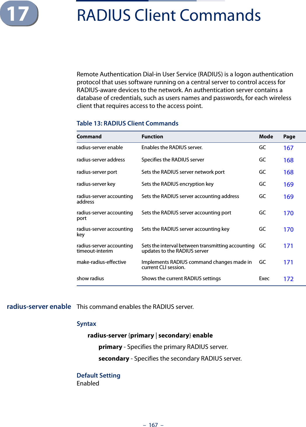
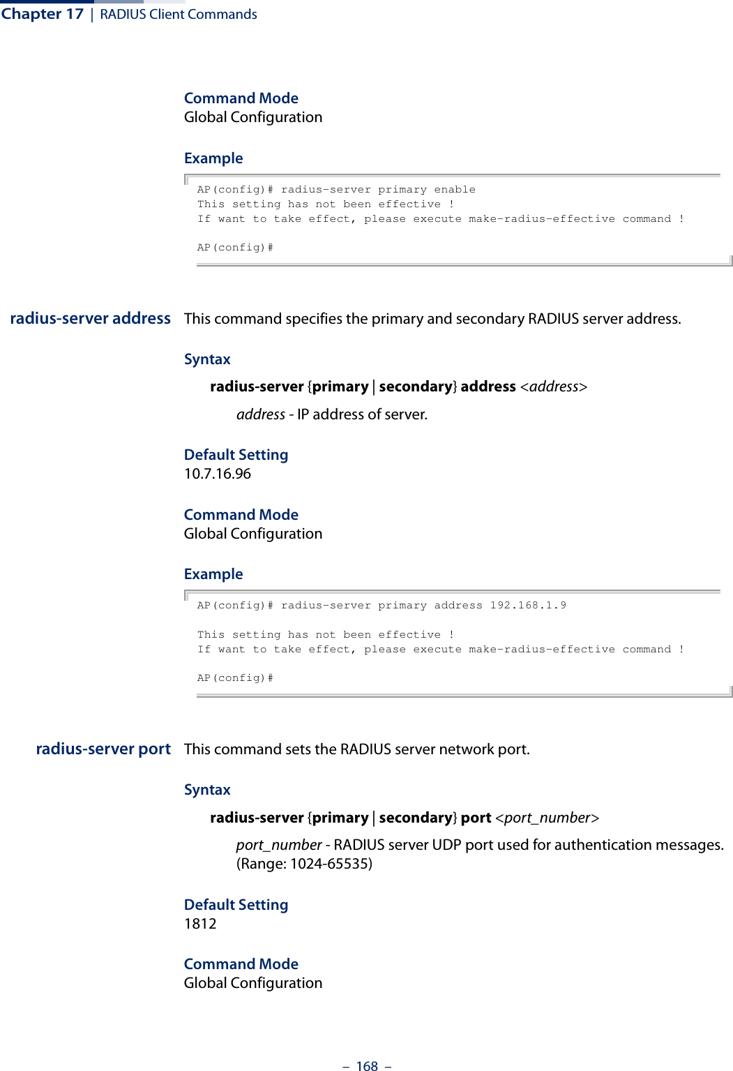
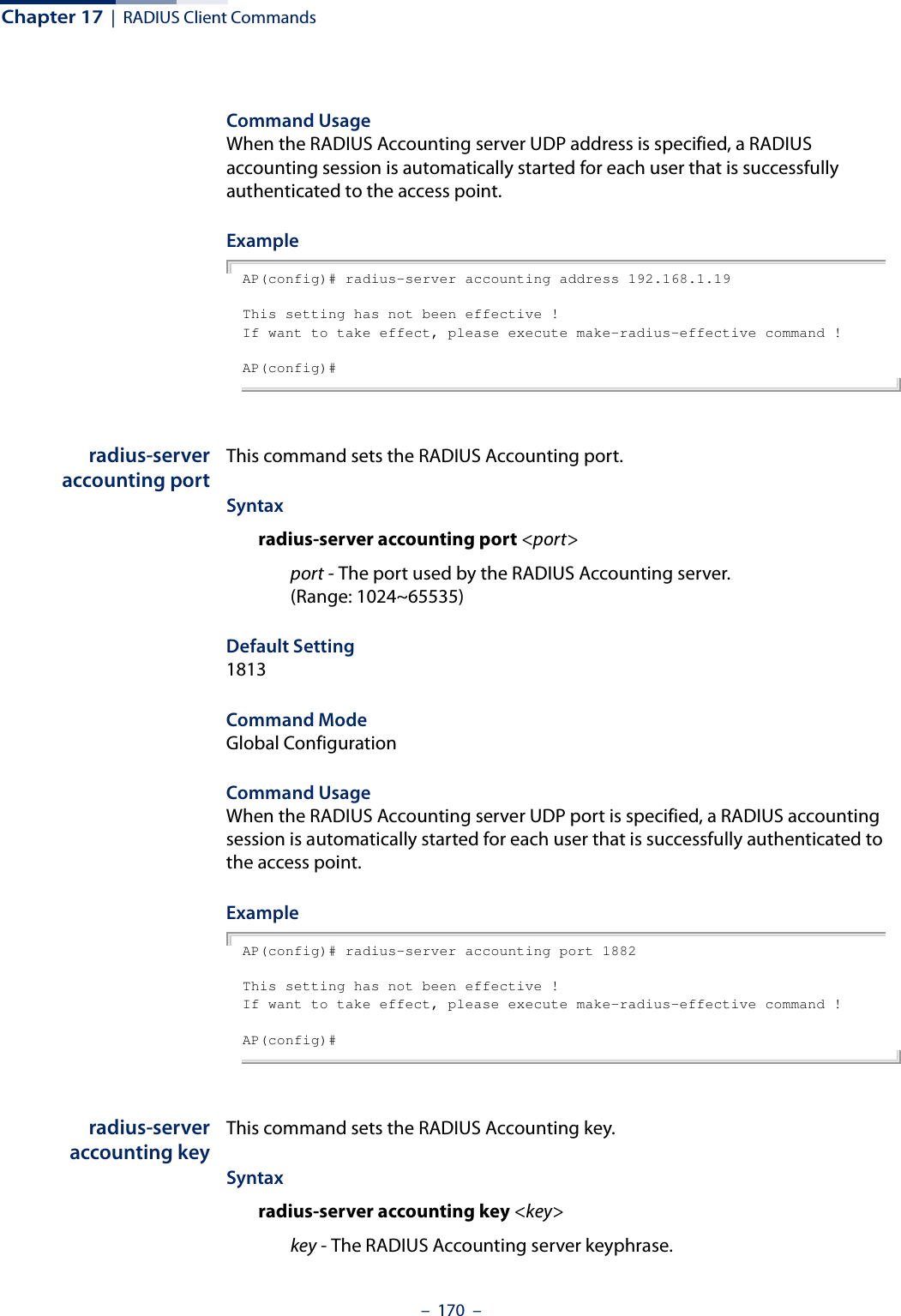
![Chapter 17 | RADIUS Client Commands– 169 –Example AP(config)# radius-server primary port 1810This setting has not been effective !If want to take effect, please execute make-radius-effective command !AP(config)#radius-server key This command sets the RADIUS encryption key. Syntax radius-server {primary | secondary] key <key_string>key_string - Encryption key used to authenticate logon access for client. Do not use blank spaces in the string. (Maximum length: 20 characters)Default Setting DEFAULTCommand Mode Global ConfigurationExample AP(config)# radius-server primary key greenThis setting has not been effective !If want to take effect, please execute make-radius-effective command !AP(config)#radius-serveraccounting addressThis command sets the RADIUS Accounting server network IP address. Syntaxradius-server accounting address <address>address - IP address of the RADIUS Accounting serverDefault Setting 10.7.16.96Command Mode Global Configuration](https://usermanual.wiki/Edgecore-Networks/SMC2891WAN.User-Manual-MG/User-Guide-1903199-Page-169.png)
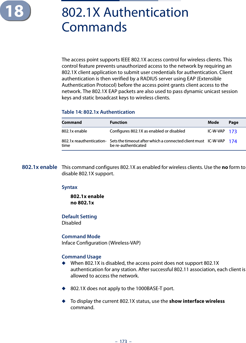
![Chapter 18 | 802.1X Authentication Commands– 174 –ExampleAP(if-wireless 0: VAP[0])# 802.1x enableThis setting has not been effective !If want to take effect, please execute make-security-effective command !AP(if-wireless 0: VAP[0])#Related Commandsshow interface wireless802.1xreauthentication-timeThis command sets the time period after which a connected client must be re-authenticated. Syntax802.1x reauthentication-time <seconds>seconds - The number of seconds. (Range: 0-1440)Default600 secondsCommand ModeInterface Configuration (Wireless-VAP)ExampleAP(if-wireless 0: VAP[0])# 802.1x reauthentication-time 600This setting has not been effective !If want to take effect, please execute make-security-effective command !AP(if-wireless 0: VAP[0])#](https://usermanual.wiki/Edgecore-Networks/SMC2891WAN.User-Manual-MG/User-Guide-1903199-Page-174.png)
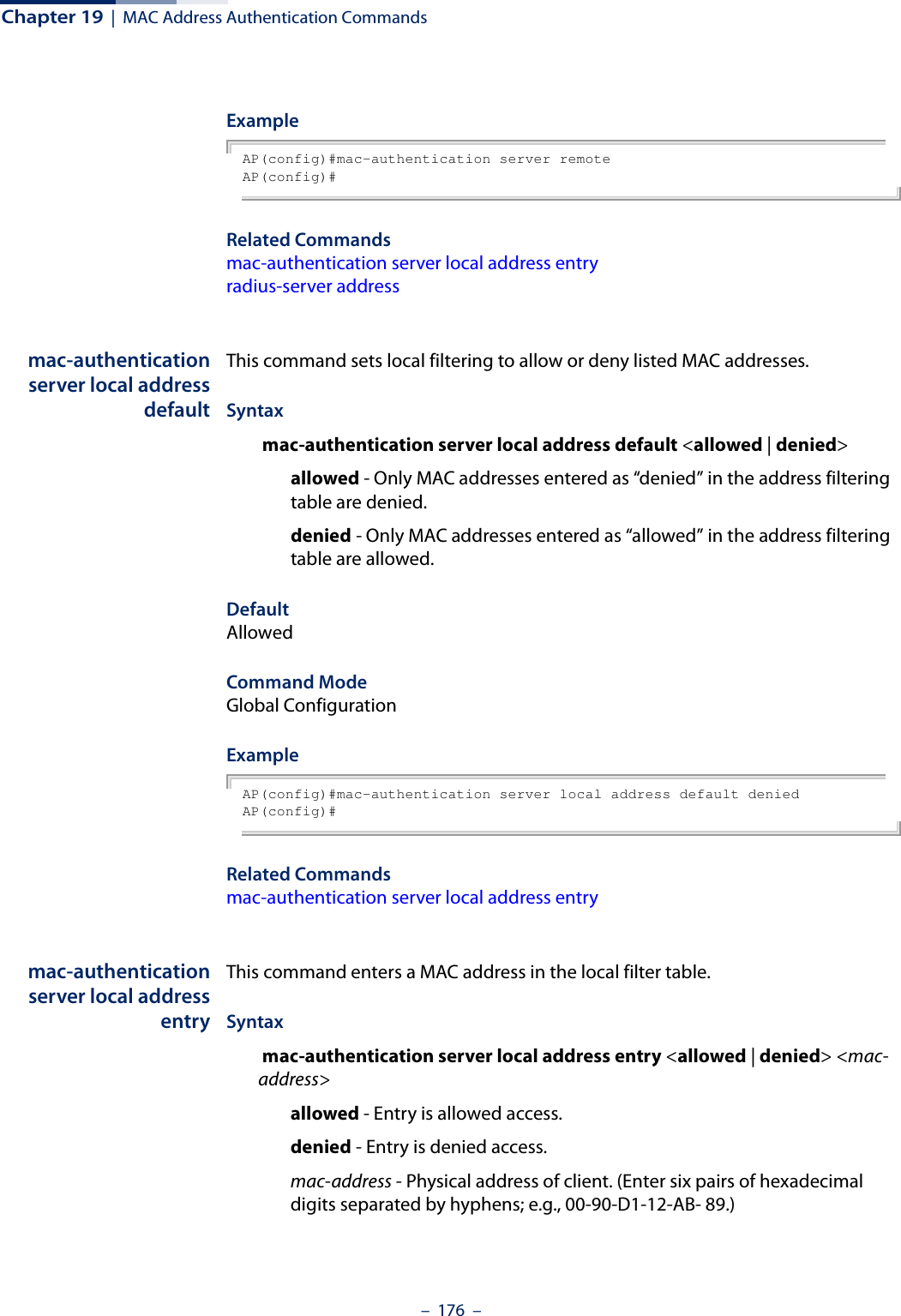
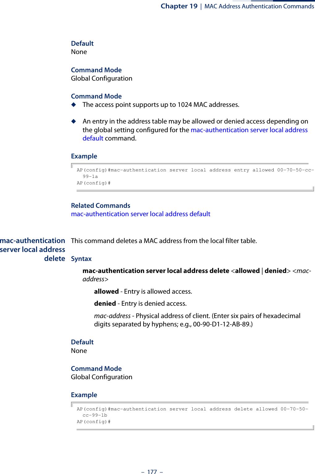
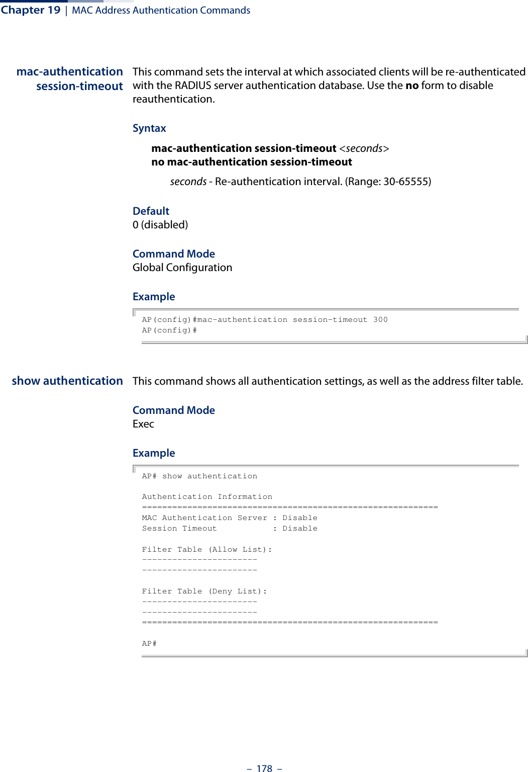
![– 175 –19 MAC Address Authentication CommandsUse these commands to define MAC authentication on the access point. For local MAC authentication, first define the default filtering policy, then enter the MAC addresses to be filtered, indicating if they are allowed or denied. For RADIUS MAC authentication, the MAC addresses and filtering policy must be configured on the RADIUS server.mac-authenticationserverThis command sets address filtering to be performed with local or remote options. Use the no form to disable MAC address authentication.Syntaxmac-authentication server [local | remote]no mac-authentication serverlocal - Authenticate the MAC address of wireless clients with the local authentication database during 802.11 association.remote - Authenticate the MAC address of wireless clients with the RADIUS server during 802.1X authentication.DefaultDisabledCommand ModeGlobal ConfigurationTable 15: MAC Address AuthenticationCommand Function Mode Pagemac-authentication server Sets address filtering to be performed with local or remote options GC 175mac-authentication server local address default Sets local filtering to allow or deny listed addresses GC 176mac-authentication server local address entry Enters a MAC address in the local filter table GC 176mac-authentication server local address delete Removes a MAC address from the local filter table GC 177mac-authentication session-timeout Sets the interval at which associated clients will be re-authenticated with the RADIUS server authentication databaseGC 178show authentication Shows all authentication settings, as well as the address filter table Exec 178](https://usermanual.wiki/Edgecore-Networks/SMC2891WAN.User-Manual-MG/User-Guide-1903199-Page-175.png)
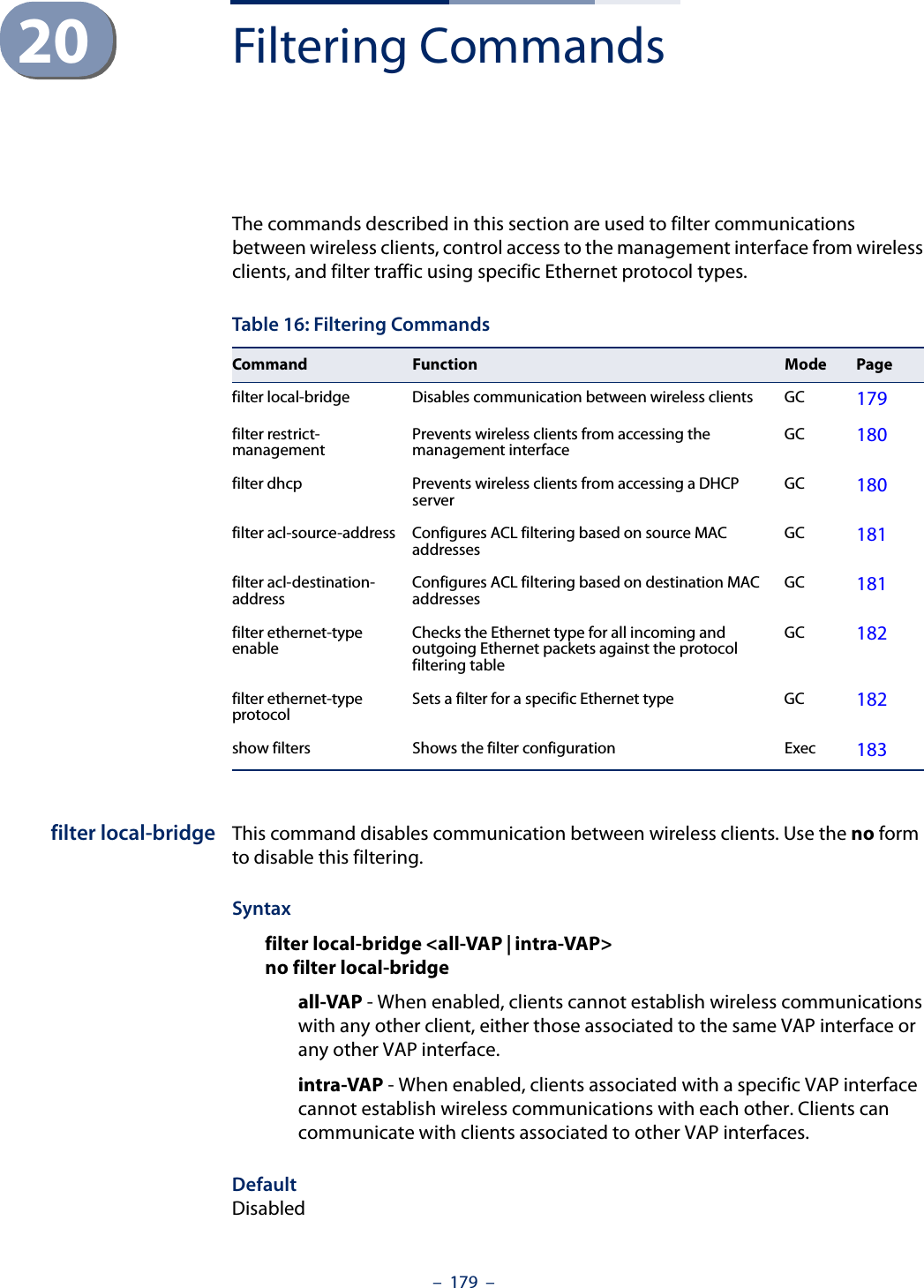
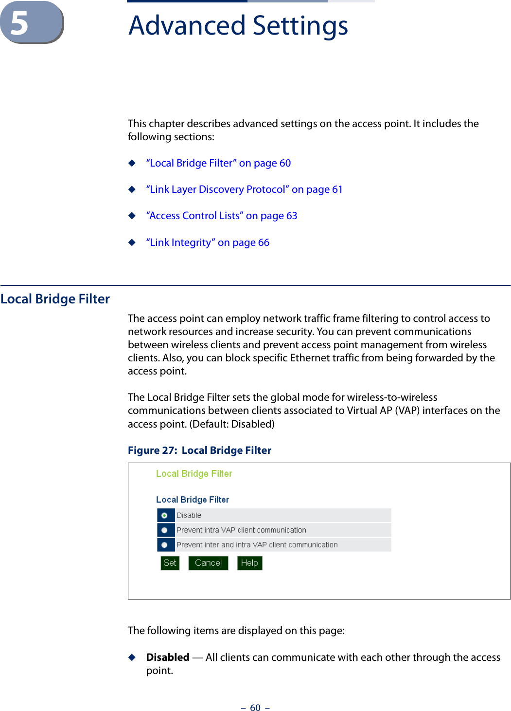
![Chapter 20 | Filtering Commands– 180 –Command ModeGlobal ConfigurationCommand UsageThis command can disable wireless-to-wireless communications between clients via the access point. However, it does not affect communications between wireless clients and the wired network.ExampleAP(config)#filter local-bridge all-vapAP(config)#filter restrict-managementThis command prevents wireless clients from accessing the management interface on the access point. Use the no form to disable this filtering.Syntax[no] filter restrict-managementDefaultDisabledCommand ModeGlobal ConfigurationExampleAP(config)#filter restrict-managementAP(config)#filter dhcp This command prevents the AP or wireless clients from obtaining an IP address from a DHCP server installed on wireless client. Syntaxfilter dhcp <enable | disable>enable - Prevent DHCP IP assignment from a wireless client.disable - Allow DHCP IP assignment from a wireless client.DefaultDisabledCommand ModeGlobal Configuration](https://usermanual.wiki/Edgecore-Networks/SMC2891WAN.User-Manual-MG/User-Guide-1903199-Page-180.png)
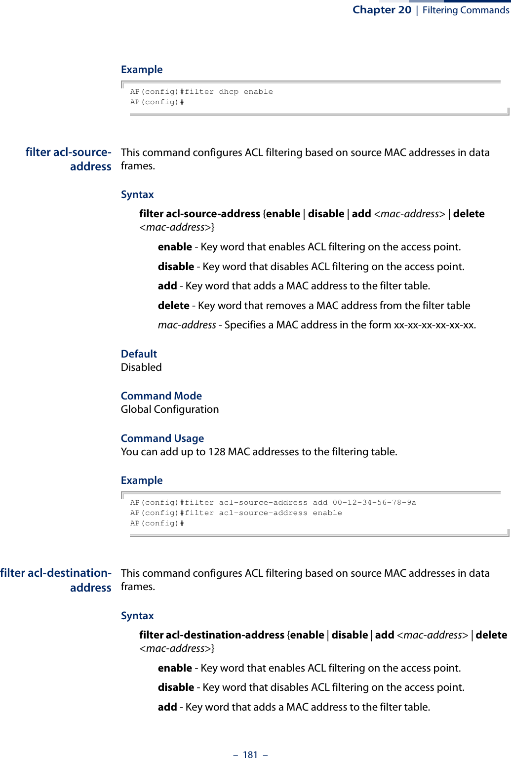
![Chapter 20 | Filtering Commands– 182 –delete - Key word that removes a MAC address from the filter tablemac-address - Specifies a MAC address in the form xx-xx-xx-xx-xx-xx.DefaultDisabledCommand ModeGlobal ConfigurationExampleAP(config)#filter acl-destination-address add 00-12-34-56-78-9aAP(config)#filter acl-destination-address enableAP(config)#filter ethernet-typeenabledThis command checks the Ethernet type on all incoming and outgoing Ethernet packets against the protocol filtering table. Use the no form to disable this feature.Syntax[no] filter ethernet-type enabledDefaultDisabledCommand ModeGlobal ConfigurationCommand UsageThis command is used in conjunction with the filter ethernet-type protocol command to determine which Ethernet protocol types are to be filtered.ExampleAP(config)#filter ethernet-type enabledAP(config)#Related Commandsfilter ethernet-type protocolfilter ethernet-typeprotocolThis command sets a filter for a specific Ethernet type. Use the no form to disable filtering for a specific Ethernet type.Syntax[no] filter ethernet-type protocol <protocol>](https://usermanual.wiki/Edgecore-Networks/SMC2891WAN.User-Manual-MG/User-Guide-1903199-Page-182.png)
![Chapter 20 | Filtering Commands– 183 –protocol - An Ethernet protocol type. (Options: ARP, RARP, Berkeley-Trailer-Negotiation, LAN-Test, X25-Level-3, Banyan, CDP, DEC XNS, DEC-MOP-Dump-Load, DEC-MOP, DEC-LAT, Ethertalk, Appletalk-ARP, Novell-IPX(old), Novell-IPX(new), EAPOL, Telxon-TXP, Aironet-DDP, Enet-Config-Test, IP, IPv6, NetBEUI, PPPoE_Discovery, PPPoE_PPP_Session)DefaultNoneCommand ModeGlobal ConfigurationCommand UsageUse the filter ethernet-type enable command to enable filtering for Ethernet types specified in the filtering table, or the no filter ethernet-type enable command to disable all filtering based on the filtering table.ExampleAP(config)#filter ethernet-type protocol ARPAP(config)#Related Commandsfilter ethernet-type enabledshow filters This command shows the filter options and protocol entries in the filter table. Syntaxshow filters [acl-source-address | acl-destination-address]Command ModeExecExampleAP#show filtersProtocol Filter Information=======================================================================Local Bridge :Traffic among all client STAs blockedAP Management :DISABLEDEtherType Filter :DISABLEDEnabled EtherType Filters-----------------------------------------------------------------------=======================================================================AP#](https://usermanual.wiki/Edgecore-Networks/SMC2891WAN.User-Manual-MG/User-Guide-1903199-Page-183.png)

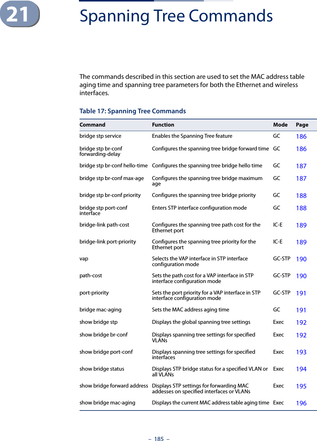
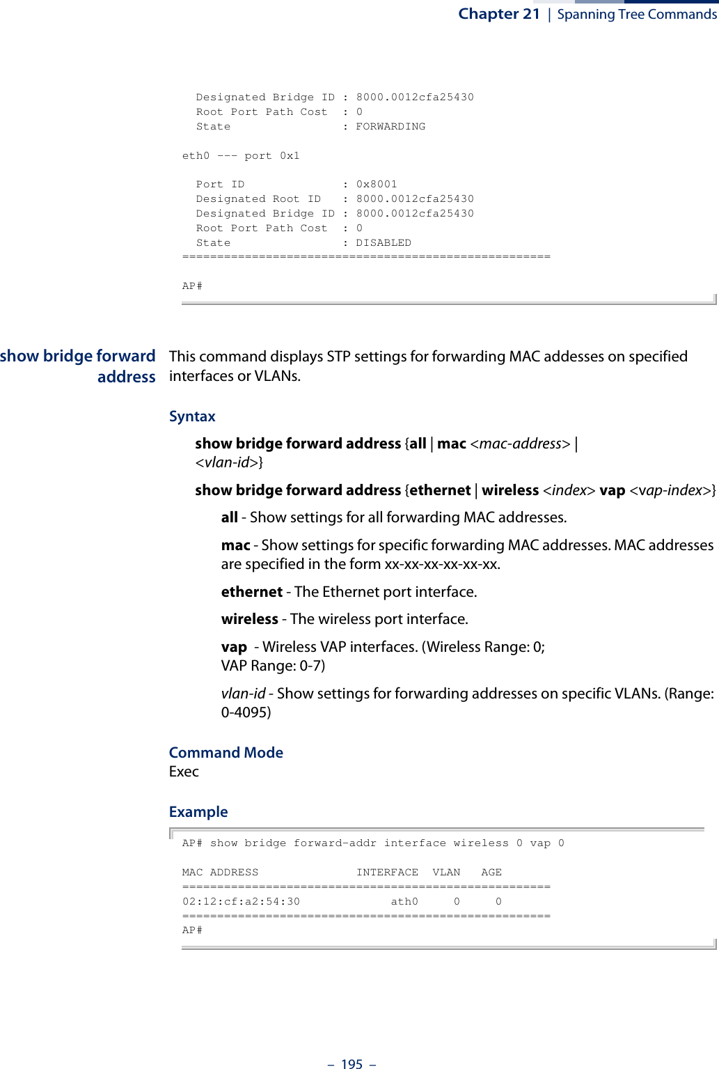
![Chapter 21 | Spanning Tree Commands– 186 –bridge stp service This command enables the Spanning Tree Protocol. Use the no form to disable the Spanning Tree Protocol.Syntax [no] bridge stp serviceDefault Setting EnabledCommand Mode Global ConfigurationExample This example globally enables the Spanning Tree Protocol.AP(config)bridge stp serviceAP(config)bridge stp br-confforwarding-delayUse this command to configure the spanning tree bridge forward time globally for the wireless bridge.Syntax bridge stp br-conf forwarding-delay <seconds>seconds - Time in seconds. (Range: 4 - 30 seconds)The minimum value is the higher of 4 or [(max-age / 2) + 1]. Default Setting 15 secondsCommand Mode Global ConfigurationCommand Usage This command sets the maximum time (in seconds) the root device will wait before changing states (i.e., discarding to learning to forwarding). This delay is required because every device must receive information about topology changes before it starts to forward frames. In addition, each port needs time to listen for conflicting information that would make it return to the discarding state; otherwise, temporary data loops might result.ExampleAP(config)#bridge stp br-conf forwarding-delay 20AP(config)#](https://usermanual.wiki/Edgecore-Networks/SMC2891WAN.User-Manual-MG/User-Guide-1903199-Page-186.png)
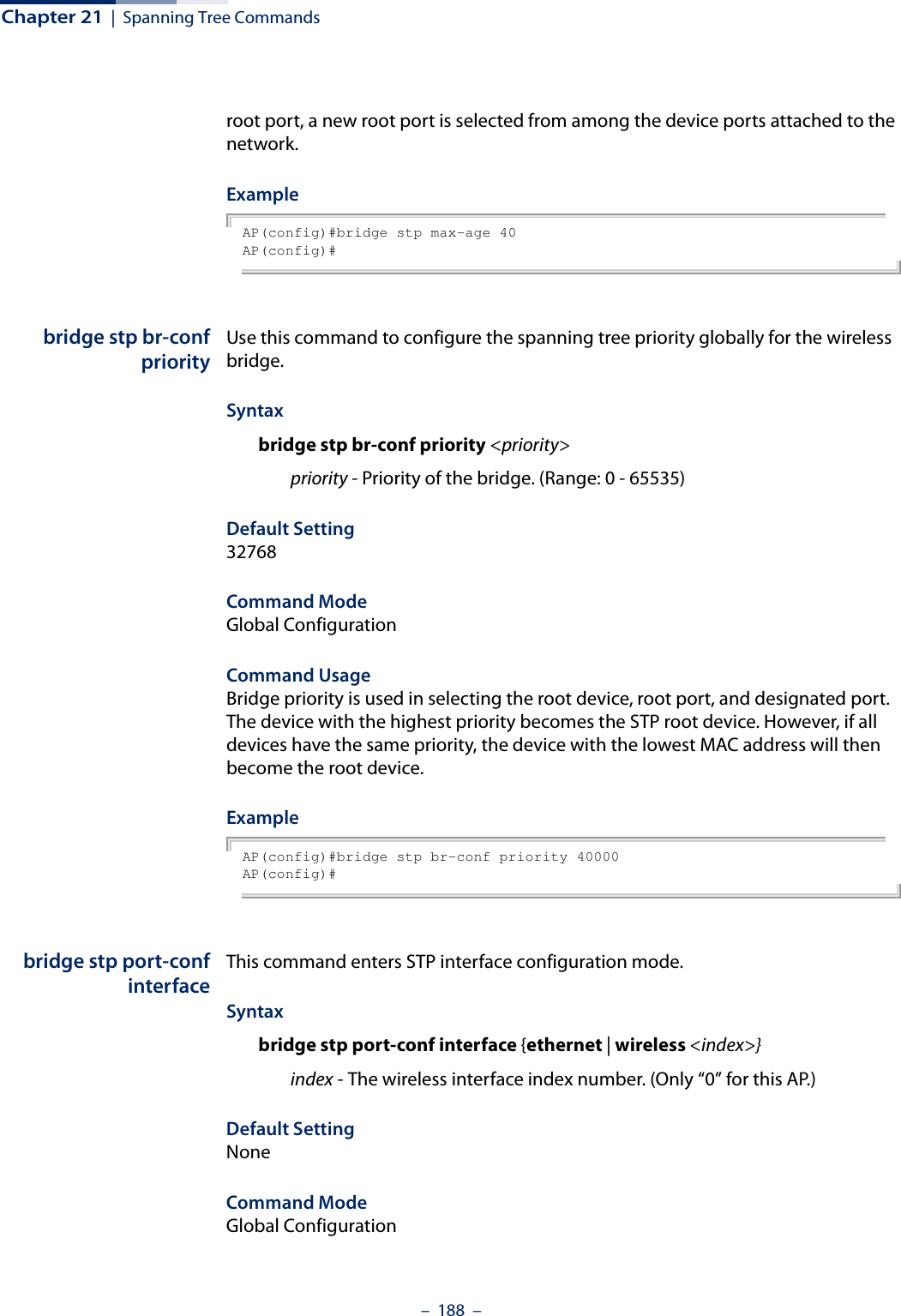
![Chapter 21 | Spanning Tree Commands– 187 –bridge stp br-confhello-timeUse this command to configure the spanning tree bridge hello time globally for the wireless bridge.Syntax bridge stp br-conf hello-time <time>time - Time in seconds. (Range: 1-10 seconds). The maximum value is the lower of 10 or [(max-age / 2) -1]. Default Setting 2 secondsCommand Mode Global ConfigurationCommand Usage This command sets the time interval (in seconds) at which the root device transmits a configuration message.Example AP(config)#bridge stp br-conf hello-time 5AP(config)#bridge stp br-confmax-ageUse this command to configure the spanning tree bridge maximum age globally for the wireless bridge.Syntax bridge stp br-conf max-age <seconds>seconds - Time in seconds. (Range: 6-40 seconds)The minimum value is the higher of 6 or [2 x (hello-time + 1)].The maximum value is the lower of 40 or [2 x (forward-time - 1)].Default Setting 20 secondsCommand Mode Global ConfigurationCommand Usage This command sets the maximum time (in seconds) a device can wait without receiving a configuration message before attempting to reconfigure. All device ports (except for designated ports) should receive configuration messages at regular intervals. Any port that ages out STP information (provided in the last configuration message) becomes the designated port for the attached LAN. If it is a](https://usermanual.wiki/Edgecore-Networks/SMC2891WAN.User-Manual-MG/User-Guide-1903199-Page-187.png)
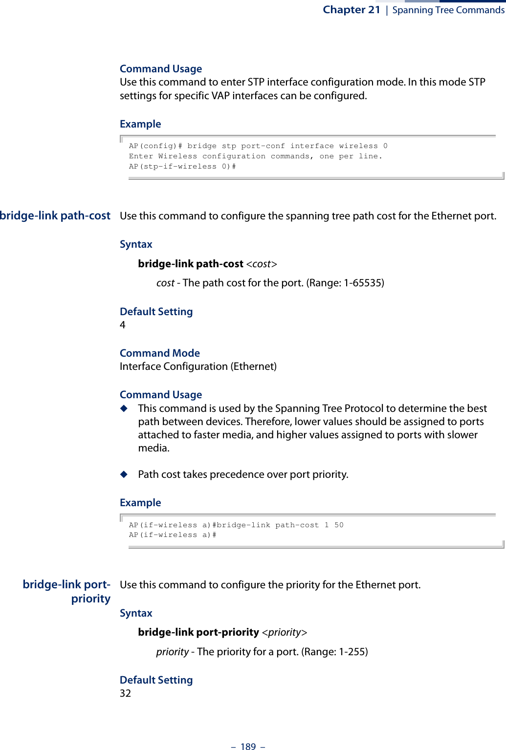
![Chapter 21 | Spanning Tree Commands– 190 –Command Mode Interface Configuration (Ethernet)Command Usage ◆This command defines the priority for the use of a port in the Spanning Tree Protocol. If the path cost for all ports on a wireless bridge are the same, the port with the highest priority (that is, lowest value) will be configured as an active link in the spanning tree. ◆Where more than one port is assigned the highest priority, the port with lowest numeric identifier will be enabled.Example AP(if-wireless a)#bridge-link port-priority 1 64AP(if-wireless a)#Related Commandsbridge-link path-costvap (STP Interface) This command selects the VAP interface for configuring STP settings.Syntaxvap <vap-index>vap-index - The index number for the VAP interface. (Range: 0-7)Command ModeGlobal Configuration (STP interface)ExampleAP(stp-if-wireless 0)# vap 0AP(stp-if-wireless 0: VAP[0])# path-cost (STPInterface)This command sets the spanning tree path cost for the VAP interface.Syntaxpath-cost <cost>cost - The path cost for the VAP interface. (Range: 1-65535)Command ModeGlobal Configuration (STP interface)](https://usermanual.wiki/Edgecore-Networks/SMC2891WAN.User-Manual-MG/User-Guide-1903199-Page-190.png)
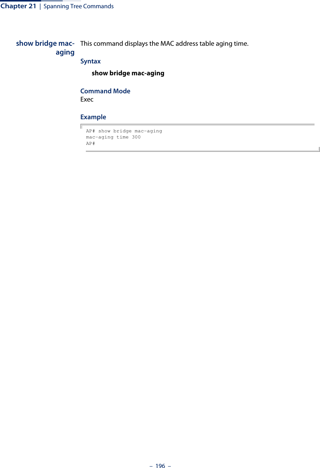
![Chapter 21 | Spanning Tree Commands– 191 –Command Usage◆This command is used by the Spanning Tree Protocol to determine the best path between devices. Therefore, lower values should be assigned to interfaces with faster media, and higher values assigned to interfaces with slower media.◆Path cost takes precedence over port priority.ExampleAP(stp-if-wireless 0: VAP[0])# path-cost 512AP(stp-if-wireless 0: VAP[0])#port-priority (STPInterface)This command sets the spanning tree path cost for the VAP interface.Syntaxport-priority <priority>priority - The priority for the VAP interface. (Range: 0-63)Command ModeGlobal Configuration (STP interface)Command Usage◆This command defines the priority for the use of an interface in the Spanning Tree Protocol. If the path cost for all interfaces on a bridge are the same, the interface with the highest priority (that is, lowest value) will be configured as an active link in the spanning tree.◆Where more than one interface is assigned the highest priority, the interface with lowest numeric identifier will be enabled.ExampleAP(stp-if-wireless 0: VAP[0])# port-priority 10AP(stp-if-wireless 0: VAP[0])#bridge mac-aging This command sets the MAC address table aging time.Syntaxbridge mac-aging <aging-time>aging-time - The time after which a learned MAC address is discarded. (Range: 10-1000000 seconds)Default300 seconds](https://usermanual.wiki/Edgecore-Networks/SMC2891WAN.User-Manual-MG/User-Guide-1903199-Page-191.png)
![– 197 –22 WDS Bridge CommandsThe commands described in this section are used to set the operation mode for each access point interface and configure Wireless Distribution System (WDS) forwarding table settings. wds ap This command enables the bridge operation mode for the radio interface.Syntaxwds apDefault Setting DisabledCommand Mode Interface Configuration (Wireless) VAPExample AP(if-wireless 0 [VAP 0])#wds apAP(if-wireless 0 [VAP 0])#wds sta This command configures WDS station mode on a VAP interface.Syntaxwds sta ap-ssid <ssid> address <mac-address>ssid - Severice set identifier. Maximum: 32 characters.mac-address - The MAC address of the connecting VAP in WDS-AP mode.Table 18: WDS Bridge CommandsCommand Function Mode Pagewds ap Selects the bridge operation mode for a radio interface IC-W VAP 197wds sta Configures the MAC addresses of the parent bridge node IC-W VAP 197show wds wireless Configures MAC addresses of connected child bridge nodes Exec 198](https://usermanual.wiki/Edgecore-Networks/SMC2891WAN.User-Manual-MG/User-Guide-1903199-Page-197.png)
![Chapter 22 | WDS Bridge Commands– 198 –Default Setting NoneCommand Mode Interface Configuration (Wireless) VAPCommand Usage In WDS-STA mode, the VAP operates as a client station in WDS mode, which connects to an access point in WDS-AP mode. The user needs to specify the SSID and MAC address of the VAP to which it intends to connect.Example AP(if-wireless 0 [VAP 0])#wds sta ap-ssid red address 00-11-22-33-44-55AP(if-wireless 0 [VAP 0])#show wds wireless This command displays the current WDS settings for VAPs.Syntaxshow wds wireless <index> vap {all | <vap-index>}index -The wireless interface index number. (Option: 0)vap-index - The VAP index number. (Range: 0-7)Command Mode ExecExample AP# show wds wireless 0 vap 0WDS Status(wireless 0 vap 0)==========================================Status: upMode: STAAP SSID: redAP MAC: 00:11:22:33:44:55==========================================AP#](https://usermanual.wiki/Edgecore-Networks/SMC2891WAN.User-Manual-MG/User-Guide-1903199-Page-198.png)
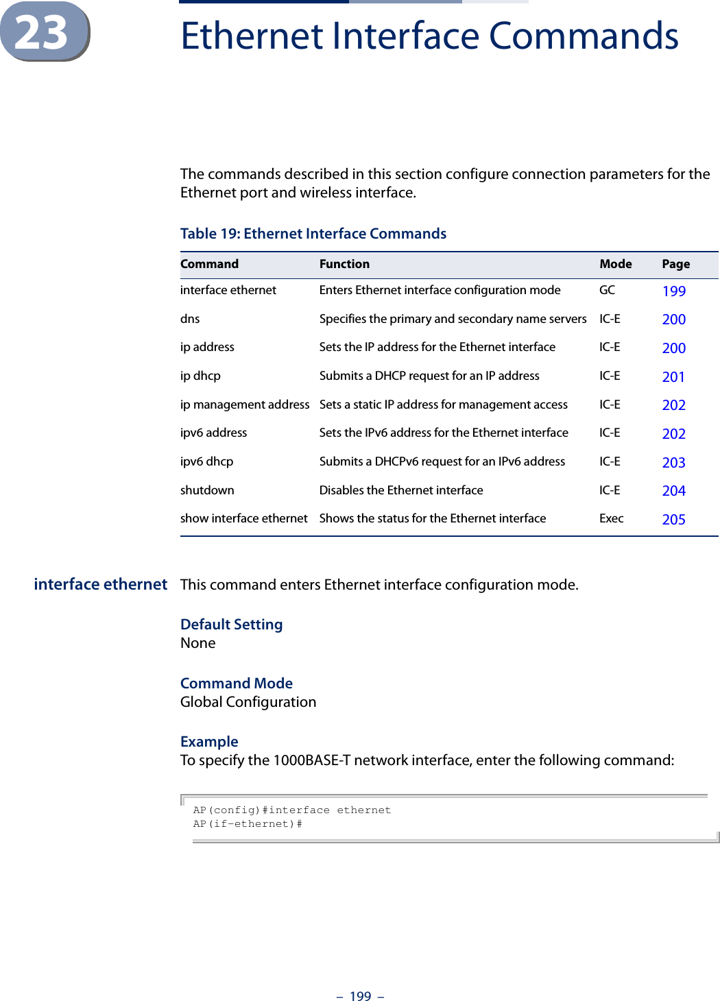
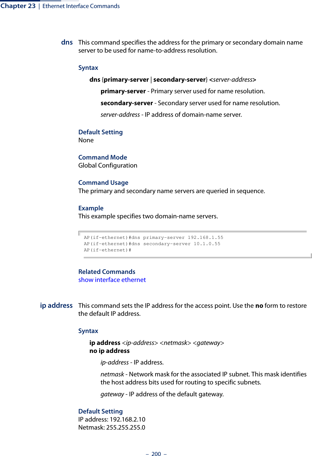
![Chapter 23 | Ethernet Interface Commands– 201 –Command Mode Interface Configuration (Ethernet)Command Usage ◆DHCP is disabled by default. If DHCP is enabled, you must first disable the DHCP client with the no ip dhcp command before you manually configure a new IP address.◆You must assign an IP address to this device to gain management access over the network or to connect the access point to existing IP subnets. You can manually configure a specific IP address using this command, or direct the device to obtain an address from a DHCP server using the ip dhcp command. Valid IP addresses consist of four numbers, 0 to 255, separated by periods. Anything other than this format will not be accepted by the configuration program. ExampleAP(config)#interface ethernetEnter Ethernet configuration commands, one per line.AP(if-ethernet)#ip address 192.168.1.2 255.255.255.0 192.168.1.253AP(if-ethernet)#Related Commandsip dhcpip dhcp This command enables the access point to obtain an IP address from a DHCP server. Use the no form to restore the default IP address.Syntax [no] ip dhcpDefault Setting DisabledCommand Mode Interface Configuration (Ethernet)Command Usage ◆You must assign an IP address to this device to gain management access over the network or to connect the access point to existing IP subnets. You can manually configure a specific IP address using the ip address command, or direct the device to obtain an address from a DHCP server using this command. ◆When you use this command, the access point will begin broadcasting DHCP client requests. The current IP address will continue to be effective until a DHCP reply is received. Requests will be broadcast periodically by this device in an](https://usermanual.wiki/Edgecore-Networks/SMC2891WAN.User-Manual-MG/User-Guide-1903199-Page-201.png)
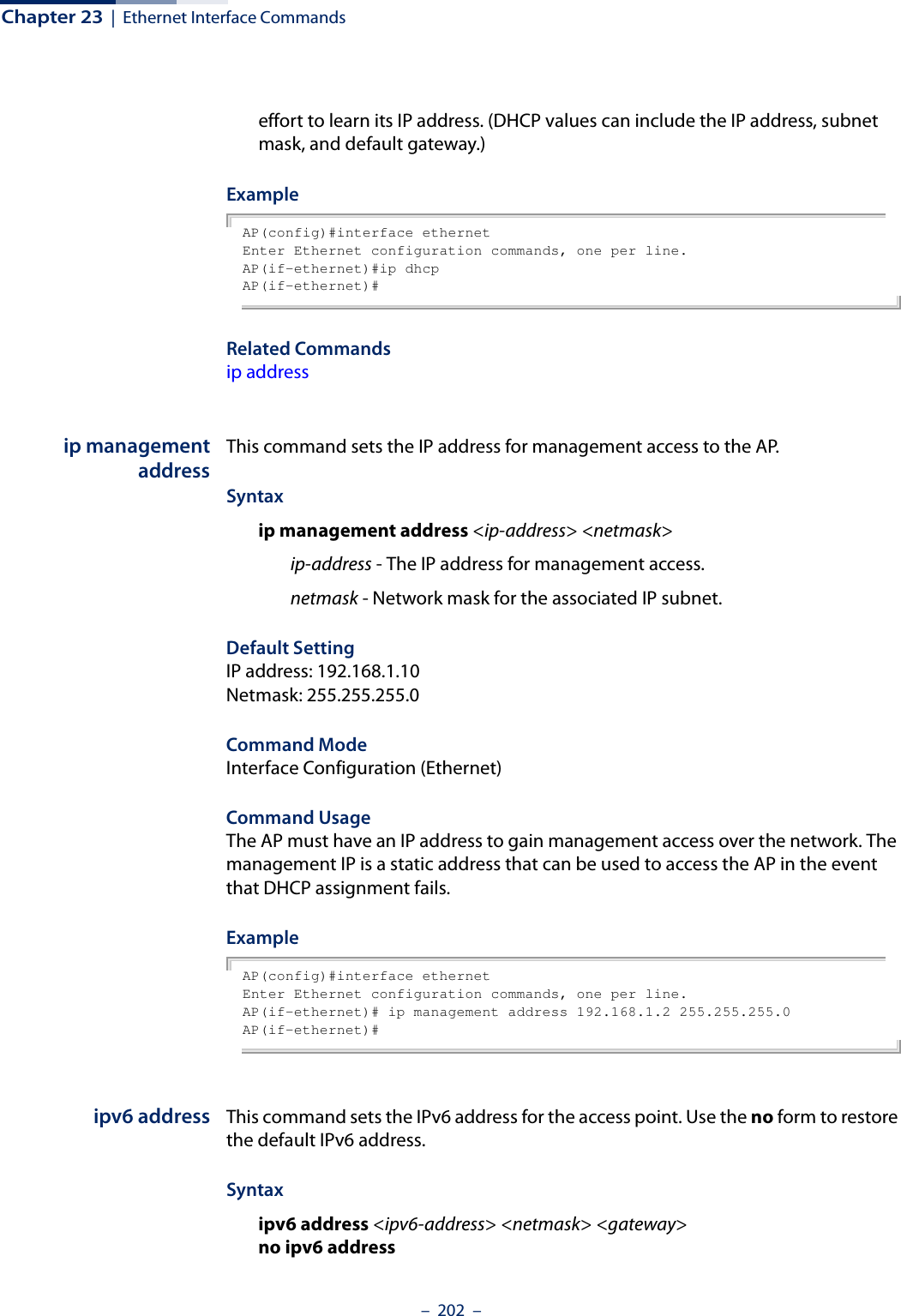
![Chapter 23 | Ethernet Interface Commands– 203 –ipv6-address - IPv6 address. netmask - Network mask for the associated IPv6 subnet. This mask identifies the host address bits used for routing to specific subnets. gateway - IPv6 address of the default gateway.Default Setting IP address: 2001:db8::1Netmask: 64Gateway: 2001:db8::2Command Mode Interface Configuration (Ethernet)Command Usage ◆DHCPv6 is disabled by default. To manually configure a new IPv6 address, you must first disable the DHCPv6 client with the no ipv6 dhcp command.◆You must assign an IPv6 address to this device to gain management access over the network or to connect the access point to existing IPv6 subnets. You can manually configure a specific IPv6 address using this command, or direct the device to obtain an address from a DHCPv6 server using the ipv6 dhcp command. ExampleAP(config)#interface ethernetEnter Ethernet configuration commands, one per line.Enterprise AP(if-ethernet)#ipv6 address 2001:db8::10 64 2001:db8::19AP(if-ethernet)#Related Commandsipv6 dhcpipv6 dhcp This command enables the access point to obtain an IPv6 address from a DHCPv6 server. Use the no form to restore the default IPv6 address.Syntax [no] ipv6 dhcpDefault Setting DisabledCommand Mode Interface Configuration (Ethernet)](https://usermanual.wiki/Edgecore-Networks/SMC2891WAN.User-Manual-MG/User-Guide-1903199-Page-203.png)
![Chapter 23 | Ethernet Interface Commands– 204 –Command Usage ◆You must assign an IPv6 address to this device to gain management access over the network or to connect the access point to existing IPv6 subnets. You can manually configure a specific IPv6 address using the ipv6 address command, or direct the device to obtain an address from a DHCPv6 server using this command. ◆When you use this command, the access point will begin broadcasting DHCPv6 client requests. The current IPv6 address (i.e., default or manually configured address) will continue to be effective until a DHCPv6 reply is received. Requests will be broadcast periodically by this device in an effort to learn its IPv6 address. (DHCPv6 values can include the IPv6 address, subnet mask, and default gateway.) ExampleAP(config)#interface ethernetEnter Ethernet configuration commands, one per line.AP(if-ethernet)#ipv6 dhcpAP(if-ethernet)#Related Commandsipv6 addressshutdown (Ethernet) This command disables the Ethernet interface. To restart a disabled interface, use the no form.Syntax [no] shutdownDefault Setting Interface enabledCommand Mode Interface Configuration (Ethernet)Command Usage This command allows you to disable the Ethernet port due to abnormal behavior (e.g., excessive collisions), and reenable it after the problem has been resolved. You may also want to disable the Ethernet port for security reasons. Example The following example disables the Ethernet port.AP(if-ethernet)#shutdownAP(if-ethernet)#](https://usermanual.wiki/Edgecore-Networks/SMC2891WAN.User-Manual-MG/User-Guide-1903199-Page-204.png)
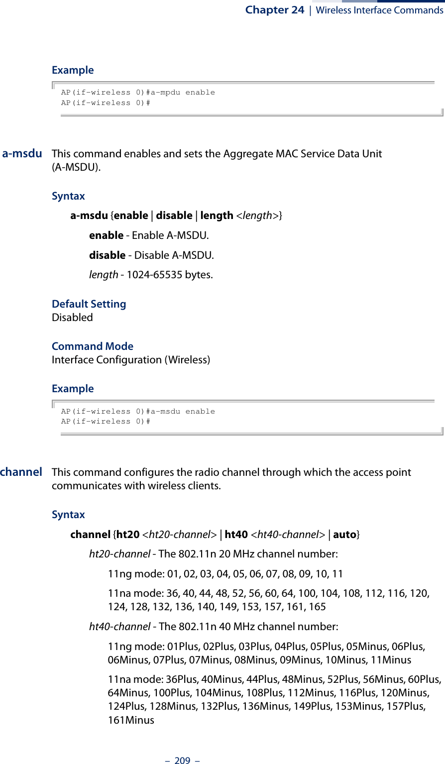
![Chapter 24 | Wireless Interface Commands– 208 –Command Mode Global Configuration Example AP(config)# interface wireless 0Enter Wireless configuration commands, one per line.AP(if-wireless 0)#vap This command provides access to the VAP (Virtual Access Point) interface configuration mode.Syntaxvap <vap-index>vap-index - The number that identifies the VAP interface. (Options: 0-15)Default Setting NoneCommand Mode Interface Configuration (Wireless)ExampleAP(if-wireless 0)#vap 0AP(if-wireless 0: VAP[0])#a-mpdu This command enables and sets the Aggregate MAC Protocol Data Unit (A-MPDU).Syntaxa-mpdu {enable | disable | length | <length >}enable - Enable A-MPDU.disable - Disable A-MPDU.length - 1024-65535 bytes.Default Setting DisabledCommand Mode Interface Configuration (Wireless)](https://usermanual.wiki/Edgecore-Networks/SMC2891WAN.User-Manual-MG/User-Guide-1903199-Page-208.png)
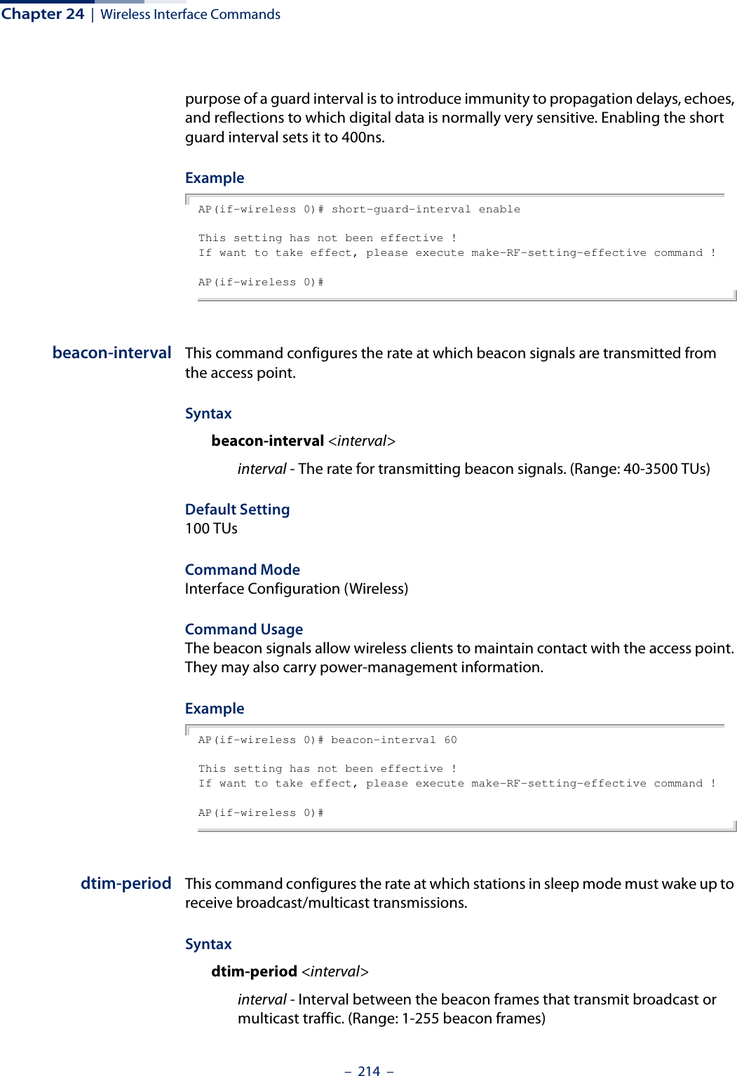
![Chapter 24 | Wireless Interface Commands– 213 –preamble This command sets the length of the signal preamble that is used at the start of a 802.11b/g data transmission.Syntaxpreamble [long | short-or-long]long - Sets the preamble to long (192 microseconds).short-or-long - Sets the preamble to short if no 802.11b clients are detected (96 microseconds).Default SettingShort-or-LongCommand ModeInterface Configuration (Wireless)Command Usage◆Using a short preamble instead of a long preamble can increase data throughput on the access point, but requires that all clients can support a short preamble.◆Set the preamble to long to ensure the access point can support all 802.11b and 802.11g clients.ExampleAP(if-wireless 0)# preamble short-or-longThis setting has not been effective !If want to take effect, please execute make-RF-setting-effective command !AP(if-wireless 0)#short-guard-interval This command sets the 802.11n guard interval to 400ns (short) or 800ns (long).Syntaxshort-guard-interval <enable | disable>Default SettingDisabledCommand ModeInterface Configuration (Wireless)Command UsageThe 802.11n draft specifies two guard intervals: 400ns (short) and 800ns (long). Support of the 400ns guard interval is optional for transmit and receive. The](https://usermanual.wiki/Edgecore-Networks/SMC2891WAN.User-Manual-MG/User-Guide-1903199-Page-213.png)
![Chapter 24 | Wireless Interface Commands– 216 –Command Usage ◆If the threshold is set to 1, the access point always sends RTS signals. If set to 2346, the access point never sends RTS signals. If set to any other value, and the packet size equals or exceeds the RTS threshold, the RTS/CTS (Request to Send / Clear to Send) mechanism will be enabled.◆The access point sends RTS frames to a receiving station to negotiate the sending of a data frame. After receiving an RTS frame, the station sends a CTS frame to notify the sending station that it can start sending data. ◆Access points contending for the wireless medium may not be aware of each other. The RTS/CTS mechanism can solve this “Hidden Node” problem.ExampleAP(if-wireless 0)# rts-threshold 1This setting has not been effective !If want to take effect, please execute make-RF-setting-effective command !AP(if-wireless 0)#ssid This command configures the service set identifier (SSID) of the VAP.Syntaxssid <string>string - The name of a basic service set supported by the access point. (Range: 1 - 32 characters)Default Setting 2.4 GHz: EAP9112A_11BGN_0 to 15 (for VAPs 0-15)5 GHz: EAP9112A_11NA_0 to 15 (for VAPs 0-15)Command Mode Interface Configuration (Wireless-VAP)Command Usage Clients that want to connect to the wireless network through an access point must set their SSIDs to the same as that of the access point.ExampleAP(if-wireless 0: VAP[0])# ssid net-nameThis setting has not been effective !If want to take effect, please execute make-security-effective command !AP(if-wireless 0: VAP[0])#](https://usermanual.wiki/Edgecore-Networks/SMC2891WAN.User-Manual-MG/User-Guide-1903199-Page-216.png)
![Chapter 24 | Wireless Interface Commands– 217 –closed-system This command prohibits access to clients without a pre-configured SSID. Use the no form to disable this feature.Syntax[no] closed-system Default Setting DisabledCommand Mode Interface Configuration (Wireless-VAP)Command Usage When closed system is enabled, the access point will not include its SSID in beacon messages. Nor will it respond to probe requests from clients that do not include a fixed SSID.ExampleAP(if-wireless 0: VAP[0])#closed-systemThis setting has not been effective !If want to take effect, please execute make-security-effective command !AP(if-wireless 0)#max-client This command configures the maximum number of wireless clients that can associate with a radio.Syntaxmax-client <max-clients>max-clients - The maximum number associated clients for the radio. (Range: 1-127)Default Setting 127Command Mode Interface Configuration (Wireless)Command Usage This command sets the total maximum number of clients that may associate with the radio. This includes the total clients associated to all VAP interfaces. The maximum number of clients that can associate to a specific VAP interface can be set using the max-association command.](https://usermanual.wiki/Edgecore-Networks/SMC2891WAN.User-Manual-MG/User-Guide-1903199-Page-217.png)
![Chapter 24 | Wireless Interface Commands– 218 –ExampleAP(if-wireless 0)# max-client 64This setting has not been effective !If want to take effect, please execute make-security-effective command !AP(if-wireless 0)#max-association This command configures the maximum number of wireless clients that can associate with a VAP interface.Syntaxmax-association <max-clients>max-clients - The maximum number associated clients for the VAP interface. (Range: 1-127)Default Setting 127Command Mode Interface Configuration (Wireless-VAP)Command Usage This command sets the total maximum number of clients that may associate with a VAP interface. If the value is greater than the setting for the maximum clients per radio (max-client command), the command does not take effect.ExampleAP(if-wireless 0: VAP[0])# max-association 64AP(if-wireless 0: VAP[0])#client-assoc-preempt This command enables a feature that implements a priority for associating clients when the maximum has been reached. Use the no form to disable the feature.Syntax[no] client-assoc-preemptDefault Setting DisabledCommand Mode Interface Configuration (Wireless-VAP)](https://usermanual.wiki/Edgecore-Networks/SMC2891WAN.User-Manual-MG/User-Guide-1903199-Page-218.png)
![Chapter 24 | Wireless Interface Commands– 219 –Command Usage◆When enabled, the AP applies a priority order for associating clients when the maximum clients for the VAP has been reached. The priority order is 11n clients, 11a/g clients, then 11b clients. ◆When the association pool for the VAP is full and the AP receives an association request from a high-priority (11n) client, the AP sends a disassociation to a lower priority client (11a/g or 11b) in order to be able to associate the high-priority client. If there are no lower-priority clients to disassociate, the AP will reject the association request. ExampleAP(if-wireless 0: VAP[0])# client-assoc-preemptset_vap_assoc_pri 0 0 yThis setting has not been effective !If want to take effect, please execute make-security-effective command !AP(if-wireless 0: VAP[0])#assoc-timeout-intervalThis command configures the idle time interval (when no frames are sent) after which the client is disassociated from the VAP interface.Syntaxassoc-timeout-interval <minutes>minutes - The number of minutes of inactivity before disassociation. (Range: 5-60 minutes)Default Setting 5 minutesCommand Mode Interface Configuration (Wireless-VAP)ExampleAP(if-wireless 0: VAP[0])# assoc-timeout-interval 10This setting has not been effective !If want to take effect, please execute make-security-effective command !AP(if-wireless 0: VAP[0])#](https://usermanual.wiki/Edgecore-Networks/SMC2891WAN.User-Manual-MG/User-Guide-1903199-Page-219.png)
![Chapter 24 | Wireless Interface Commands– 220 –auth-timeout-interval This command configures the time interval within which clients must complete authentication to the VAP interface.Syntaxauth-timeout-interval <minutes>minutes - The number of minutes before re-authentication. (Range: 3-60 minutes)Default Setting 3 minutesCommand Mode Interface Configuration (Wireless-VAP)ExampleAP(if-wireless 0: VAP[0])# auth-timeout-interval 10This setting has not been effective !If want to take effect, please execute make-security-effective command !AP(if-wireless 0: VAP[0])#multicast-enhance This command enables a feature that improves multicast video quality for wireless clients. Use the no form to disable the feature.Syntax[no] multicast-enhanceDefault Setting DisabledCommand Mode Interface Configuration (Wireless-VAP)Command UsageWhen a wireless client joins a multicast group, this feature converts multicast packets to unicast packets to improve multicast video quality.ExampleAP(if-wireless 0: VAP[0])# multicast-enhanceset_vap_mcastenhance 0 0 2This setting has not been effective !If want to take effect, please execute make-security-effective command !AP(if-wireless 0: VAP[0])#](https://usermanual.wiki/Edgecore-Networks/SMC2891WAN.User-Manual-MG/User-Guide-1903199-Page-220.png)
![Chapter 24 | Wireless Interface Commands– 221 –shutdown (VAP) This command disables the VAP interface. Use the no form to restart the interface.Syntax [no] shutdownDefault Setting Interface enabledCommand Mode Interface Configuration (Wireless-VAP)Command UsageYou must first enable VAP interface 0 before you can enable VAP interfaces 1 to 15.Example AP(if-wireless 0: VAP[0])# shutdownThis setting has not been effective !If want to take effect, please execute make-security-effective command !AP(if-wireless 0: VAP[0])#interfere-chan-recoverThis command rescans channels when interference is detected on the current channel. Use the no form to disable the feature.Syntax [no] interfere-chan-recoverDefault Setting DisabledCommand Mode Interface Configuration (Wireless)Command Usage◆When interference is detected on the current channel, the AP re-scans all channels and then changes to a new clear channel. ◆There is too much interference on a channel when the AP is unable to send the beacon signal more than ten times. The AP will then use its auto-channel algorithm to find a new clear channel.Example AP(if-wireless 0)# interfere-chan-recoverAP(if-wireless 0)#](https://usermanual.wiki/Edgecore-Networks/SMC2891WAN.User-Manual-MG/User-Guide-1903199-Page-221.png)
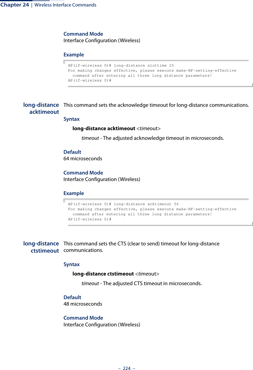
![Chapter 24 | Wireless Interface Commands– 225 –ExampleAP(if-wireless 0)# long-distance ctstimeout 56For making changes effective, please execute make-RF-setting-effective command after entering all three long distance parameters!AP(if-wireless 0)#bandwidth-controldownlinkThis command enables the downlink bandwidth control for a VAP interface.Syntaxbandwidth-control downlink <enable | disable>enable - Enables the downlink bandwidth control setting. disable - Disables the feature. DefaultDisabledCommand ModeInterface Configuration (Wireless-VAP)Command Usage This command enables the rate limiting of traffic from the wired network as it is passed to the VAP interface. You can set a maximum rate in Kbytes per second.ExampleAP(if-wireless 0: VAP[0])# bandwidth-control downlink enableThis setting has not been effective !If want to take effect, please execute make-security-effective command !AP(if-wireless 0: VAP[0])#bandwidth-controldownlink rateThis command sets the downlink bandwidth rate for a VAP interface.Syntaxbandwidth-control downlink rate <rate>rate - The allowed downlink rate in Kbytes per second. (Range: 100-12000 Kbytes per second)Default100 Kbytes per secondCommand ModeInterface Configuration (Wireless-VAP)](https://usermanual.wiki/Edgecore-Networks/SMC2891WAN.User-Manual-MG/User-Guide-1903199-Page-225.png)
![Chapter 24 | Wireless Interface Commands– 226 –ExampleAP(if-wireless 0: VAP[0])# bandwidth-control downlink rate 512This setting has not been effective !If want to take effect, please execute make-security-effective command !AP(if-wireless 0: VAP[0])#bandwidth-controluplinkThis command enables the uplink bandwidth control for a VAP interface.Syntaxbandwidth-control uplink <enable | disable>enable - Enables the uplink bandwidth control setting. disable - Disables the feature. DefaultDisabledCommand ModeInterface Configuration (Wireless-VAP)Command Usage This command enables the rate limiting of traffic from the VAP interface as it is passed to the wired network. You can set a maximum rate in Kbytes per second.ExampleAP(if-wireless 0: VAP[0])# bandwidth-control uplink enableThis setting has not been effective !If want to take effect, please execute make-security-effective command !AP(if-wireless 0: VAP[0])#bandwidth-controluplink rateThis command sets the uplink bandwidth rate for a VAP interface.Syntaxbandwidth-control uplink rate <rate>rate - The allowed uplink rate in Kbytes per second. (Range: 100-12000 Kbytes per second)Default100 Kbytes per second](https://usermanual.wiki/Edgecore-Networks/SMC2891WAN.User-Manual-MG/User-Guide-1903199-Page-226.png)
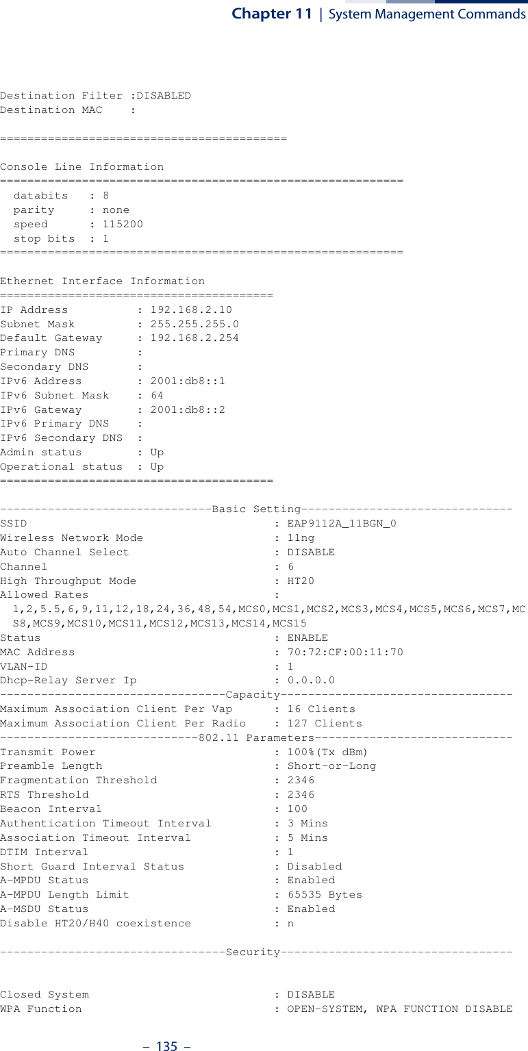
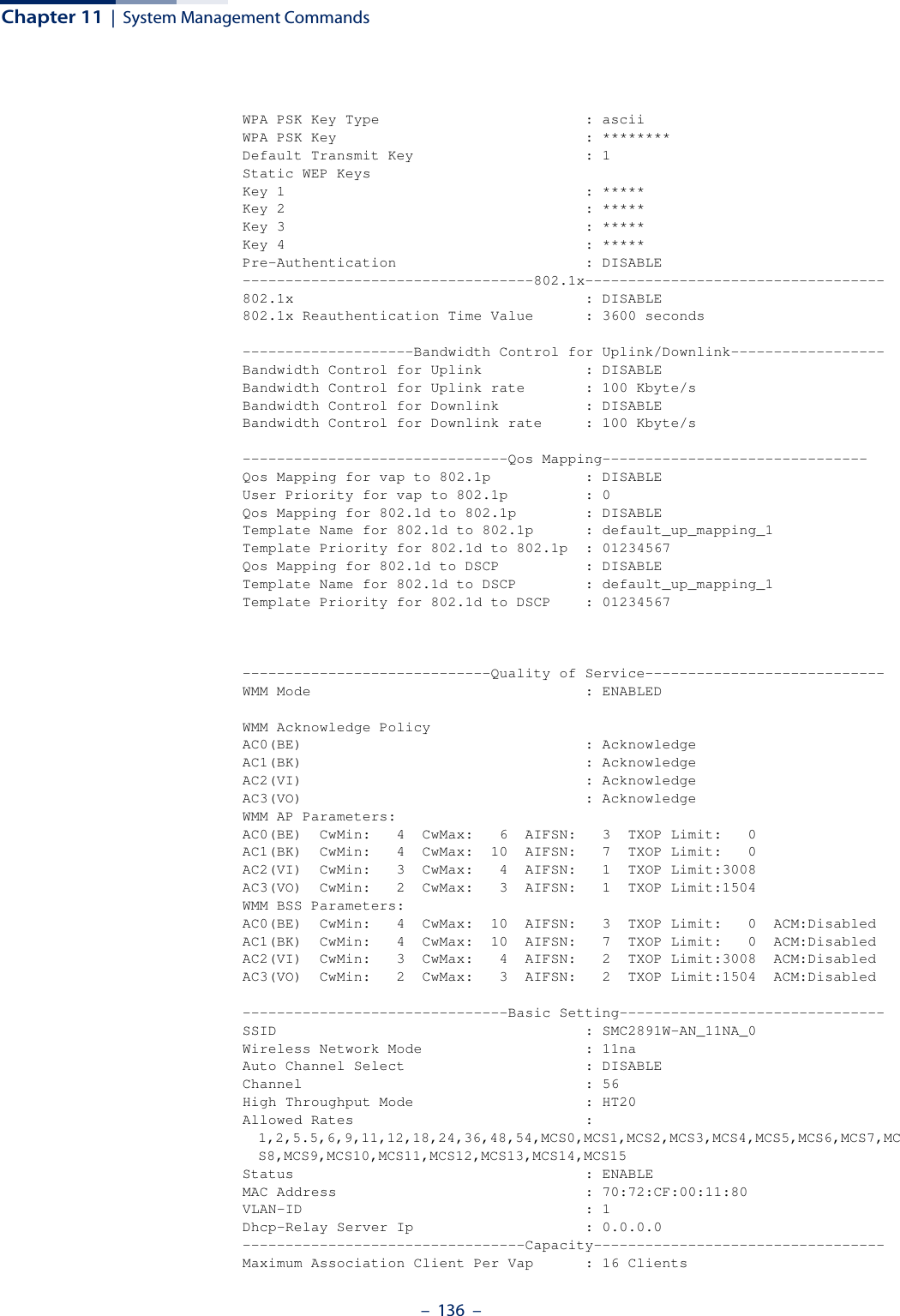
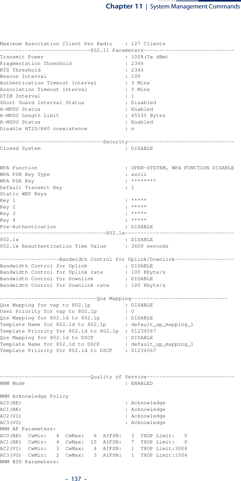
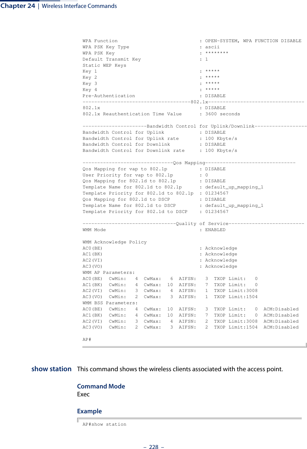
![Chapter 24 | Wireless Interface Commands– 227 –Command ModeInterface Configuration (Wireless-VAP)ExampleAP(if-wireless 0: VAP[0])# bandwidth-control uplink rate 512This setting has not been effective !If want to take effect, please execute make-security-effective command !AP(if-wireless 0: VAP[0])#show interfacewirelessThis command displays the status for a specified VAP interface.Syntaxshow interface wireless <index> vap <vap-index>index - The wireless interface slot number. (Range: 0 or 1)vap-index - The number that identifies a VAP interface. (Options: 0-15)Command Mode ExecExample AP# show interface wireless 0 vap 0----------------------------------Basic Setting----------------------------SSID : EAP9112A_11BGN_0Wireless Network Mode : 11ngAuto Channel Select : DISABLEChannel : 6High Throughput Mode : HT20Status : ENABLEVLAN-ID : 1Dhcp-Relay Server Ip : 0.0.0.0------------------------------------Capacity--------------------------------Maximum Association Client Per Vap : 16 ClientsMaximum Association Client Per Radio : 127 Clients--------------------------------802.11 Parameters---------------------------Transmit Power : 100%(20 dBm)Preamble Length : Short-or-LongFragmentation Threshold : 2346RTS Threshold : 2346Beacon Interval : 100Authentication Timeout Interval : 3 MinsAssociation Timeout Interval : 5 MinsDTIM Interval : 1Short Guard Interval Status : DisabledA-MPDU Status : EnabledA-MPDU Length Limit : 65535 BytesA-MSDU Status : Enabled------------------------------------Security--------------------------------Closed System : DISABLE](https://usermanual.wiki/Edgecore-Networks/SMC2891WAN.User-Manual-MG/User-Guide-1903199-Page-227.png)
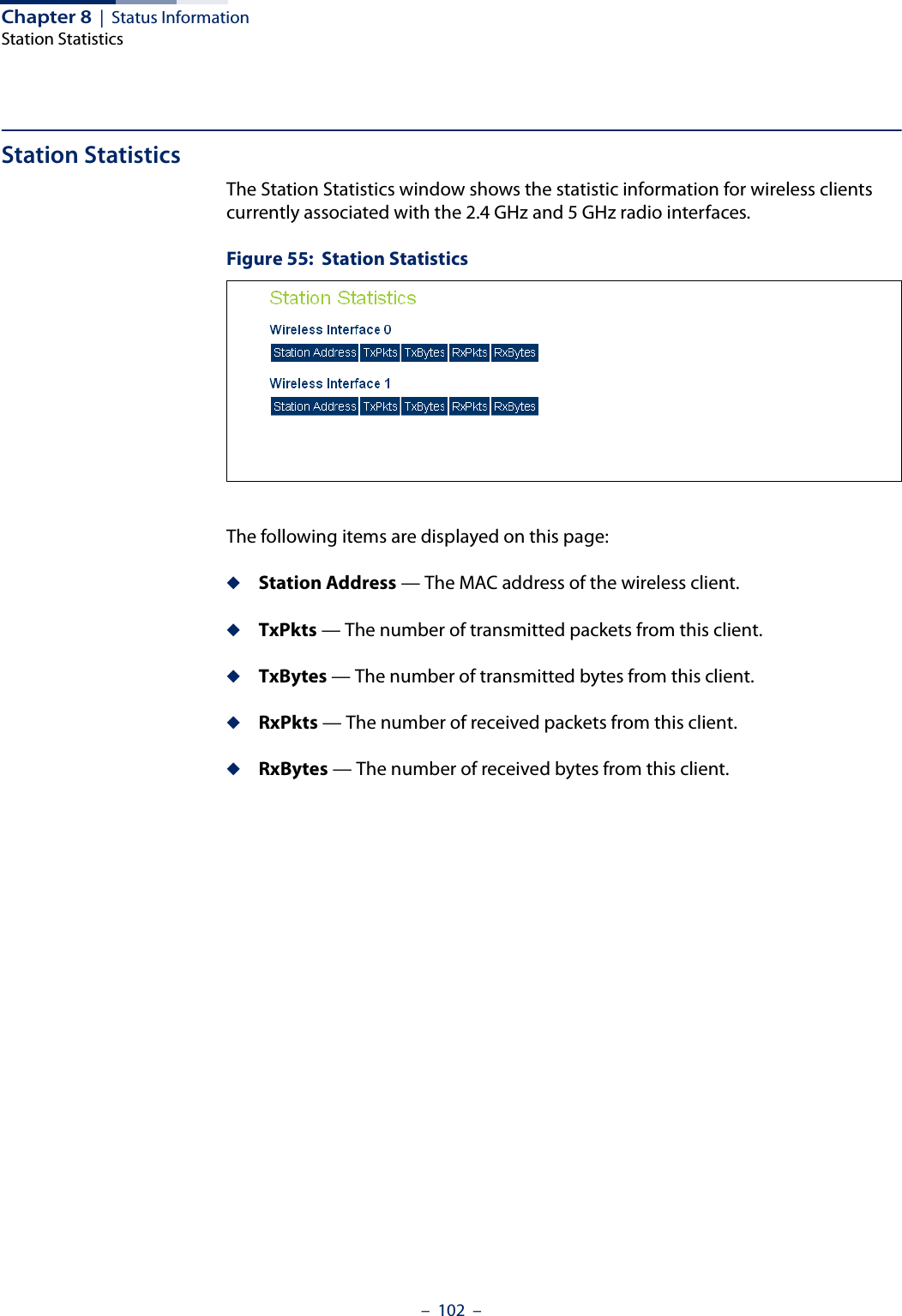
![Chapter 24 | Wireless Interface Commands– 229 –Station Table Information========================================Wireless Interface 0 VAPs List:if-wireless 0 VAP [0] :ADDR RSSI Tx(Mbps) Rx(Mbps) IP Privacy Authenticationfc:25:3f:70:1a:4f 22 0M 6M 0.0.0.0 off Openfc:25:3f:5c:32:49 20 0M 13M 0.0.0.0 off Openif-wireless 0 VAP [1] :if-wireless 0 VAP [2] :if-wireless 0 VAP [3] :if-wireless 0 VAP [4] :if-wireless 0 VAP [5] :if-wireless 0 VAP [6] :if-wireless 0 VAP [7] :if-wireless 0 VAP [8] :if-wireless 0 VAP [9] :if-wireless 0 VAP [10] :if-wireless 0 VAP [11] :if-wireless 0 VAP [12] :if-wireless 0 VAP [13] :if-wireless 0 VAP [14] :if-wireless 0 VAP [15] :Wireless Interface 1 VAPs List:if-wireless 1 VAP [0] :if-wireless 1 VAP [1] :if-wireless 1 VAP [2] :if-wireless 1 VAP [3] :if-wireless 1 VAP [4] :if-wireless 1 VAP [5] :if-wireless 1 VAP [6] :if-wireless 1 VAP [7] :if-wireless 1 VAP [8] :if-wireless 1 VAP [9] :if-wireless 1 VAP [10] :if-wireless 1 VAP [11] :if-wireless 1 VAP [12] :if-wireless 1 VAP [13] :if-wireless 1 VAP [14] :if-wireless 1 VAP [15] :========================================AP#show station statistics This command shows statistics information for wireless clients associated with the access point.Command Mode Exec](https://usermanual.wiki/Edgecore-Networks/SMC2891WAN.User-Manual-MG/User-Guide-1903199-Page-229.png)
![Chapter 24 | Wireless Interface Commands– 230 –Example AP#show station statisticsStation Table Information========================================Wireless Interface 0 VAPs List:if-wireless 0 VAP [0] :Total Station Number of this vap: 0if-wireless 0 VAP [1] :Total Station Number of this vap: 0if-wireless 0 VAP [2] :Total Station Number of this vap: 0if-wireless 0 VAP [3] :Total Station Number of this vap: 0if-wireless 0 VAP [4] :Total Station Number of this vap: 0if-wireless 0 VAP [5] :Total Station Number of this vap: 0if-wireless 0 VAP [6] :Total Station Number of this vap: 0if-wireless 0 VAP [7] :Total Station Number of this vap: 0if-wireless 0 VAP [8] :Total Station Number of this vap: 0if-wireless 0 VAP [9] :Total Station Number of this vap: 0if-wireless 0 VAP [10] :Total Station Number of this vap: 0if-wireless 0 VAP [11] :Total Station Number of this vap: 0if-wireless 0 VAP [12] :Total Station Number of this vap: 0if-wireless 0 VAP [13] :Total Station Number of this vap: 0if-wireless 0 VAP [14] :Total Station Number of this vap: 0if-wireless 0 VAP [15] :Total Station Number of this vap: 0Wireless Interface 1 VAPs List:if-wireless 1 VAP [0] :Total Station Number of this vap: 0if-wireless 1 VAP [1] :Total Station Number of this vap: 0if-wireless 1 VAP [2] :Total Station Number of this vap: 0if-wireless 1 VAP [3] :Total Station Number of this vap: 0if-wireless 1 VAP [4] :Total Station Number of this vap: 0if-wireless 1 VAP [5] :Total Station Number of this vap: 0if-wireless 1 VAP [6] :Total Station Number of this vap: 0if-wireless 1 VAP [7] :Total Station Number of this vap: 0if-wireless 1 VAP [8] :Total Station Number of this vap: 0if-wireless 1 VAP [9] :Total Station Number of this vap: 0if-wireless 1 VAP [10] :Total Station Number of this vap: 0if-wireless 1 VAP [11] :](https://usermanual.wiki/Edgecore-Networks/SMC2891WAN.User-Manual-MG/User-Guide-1903199-Page-230.png)
![Chapter 24 | Wireless Interface Commands– 231 –Total Station Number of this vap: 0if-wireless 1 VAP [12] :Total Station Number of this vap: 0if-wireless 1 VAP [13] :Total Station Number of this vap: 0if-wireless 1 VAP [14] :Total Station Number of this vap: 0if-wireless 1 VAP [15] :Total Station Number of this vap: 0========================================Total Station Number of this device: 0Total Station Number of Radio 0: 0Total Station Number of Radio 1: 0========================================AP#](https://usermanual.wiki/Edgecore-Networks/SMC2891WAN.User-Manual-MG/User-Guide-1903199-Page-231.png)
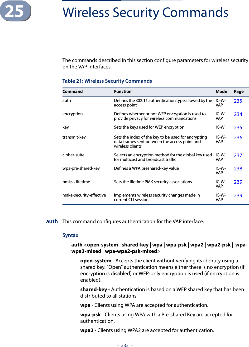
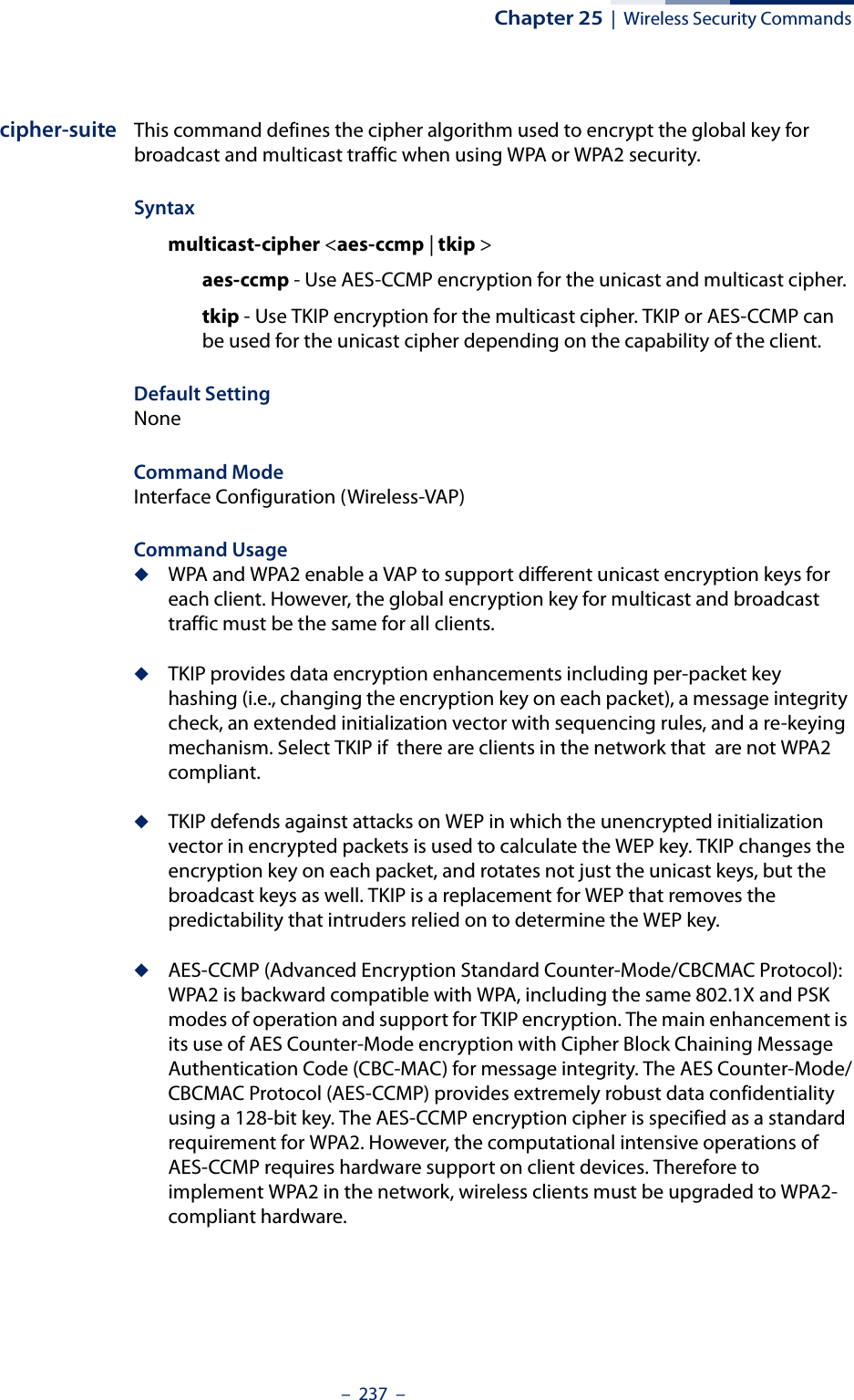
![Chapter 25 | Wireless Security Commands– 234 –◆WPA2 defines a transitional mode of operation for networks moving from WPA security to WPA2. WPA2 Mixed Mode allows both WPA and WPA2 clients to associate to a common VAP interface. When the encryption cipher suite is set to TKIP, the unicast encryption cipher (TKIP or AES-CCMP) is negotiated for each client. The access point advertises it’s supported encryption ciphers in beacon frames and probe responses. WPA and WPA2 clients select the cipher they support and return the choice in the association request to the access point. For mixed-mode operation, the cipher used for broadcast frames is always TKIP. WEP encryption is not allowed.ExampleAP(if-wireless 0: VAP[0])# auth wpa-pskAP(if-wireless 0: VAP[0])#Related Commandsencryptionkeyencryption This command enables data encryption for wireless communications. Use the no form to disable data encryption.Syntax[no] encryptionDefault Setting disabledCommand Mode Interface Configuration (Wireless-VAP)Command Usage ◆Selecting a security method using the auth command, automatically enables data encryption (WEP, TKIP, or AES-CCMP) for the VAP. Only use this command when using WEP encryption with an Open System.◆Encryption is implemented in this device to prevent unauthorized access to your wireless network. For more secure data transmissions, enable encryption by selecting a security method using the auth command, or by using the encryption command when using WEP encryption only.◆The encryption settings must be the same on each client in your wireless network.◆Note that encryption protects data transmitted between wireless nodes, but does not protect any transmissions over your wired network or over the Internet.](https://usermanual.wiki/Edgecore-Networks/SMC2891WAN.User-Manual-MG/User-Guide-1903199-Page-234.png)
![Chapter 25 | Wireless Security Commands– 235 –ExampleAP(if-wireless 0: VAP[0])# encryptionThis setting has not been effective !If want to take effect, please execute make-security-effective command !AP(if-wireless 0: VAP[0])#Related Commandskeykey This command sets the keys used for WEP encryption. Use the no form to delete a configured key.Syntaxkey {<index> <size> <type> <value> | static | dynamic}no key <index>index - Key index. (Range: 1-4)size - Key size. (Options: 64 or 128 bits)type - Input format. (Options: ASCII, HEX)value - The key string.For 64-bit keys, use 5 alphanumeric characters or 10 hexadecimal digits.For 128-bit keys, use 13 alphanumeric characters or 26 hexadecimal digits.static - Uses static WEP keys with 802.1X authentication.dynamic - When using 802.1X authentication, allows WEP keys to be dynamically generated by the RADIUS server.Default Setting NoneCommand Mode Interface Configuration (Wireless-VAP)Command Usage ◆To enable WEP, use the auth shared-key command to select the “shared key” authentication type, use the key command to configure at least one key, and then use the transmit-key command to select a key to use.◆If WEP is enabled, all wireless clients must be configured with the same shared keys to communicate with the VAP.](https://usermanual.wiki/Edgecore-Networks/SMC2891WAN.User-Manual-MG/User-Guide-1903199-Page-235.png)
![Chapter 25 | Wireless Security Commands– 236 –◆The WEP key index, length and type configured for the VAP must match those configured for clients.ExampleAP(if-wireless 0: VAP[0])# key 1 64 hex 1234512345This setting has not been effective !If want to take effect, please execute make-security-effective command !AP(if-wireless 0: VAP[0])#Related Commandskeyencryptiontransmit-keytransmit-key This command sets the index of the WEP key to be used for encrypting data frames transmitted from the VAP to wireless clients.Syntaxtransmit-key <index>index - Key index. (Range: 1-4)Default Setting 1Command Mode Interface Configuration (Wireless-VAP)Command Usage ◆If you use WEP key encryption option, the access point uses the transmit key to encrypt multicast and broadcast data signals that it sends to client devices. Other keys can be used for decryption of data from clients.◆When using dynamic keys with 802.1X, the access point uses a dynamic key to encrypt unicast and broadcast messages to 802.1X-enabled clients. However, because the access point sends the keys during the 802.1X authentication process, these keys do not have to appear in the client’s key list.ExampleAP(if-wireless 0: VAP[0])# transmit-key 1This setting has not been effective !If want to take effect, please execute make-security-effective command !AP(if-wireless 0: VAP[0])#](https://usermanual.wiki/Edgecore-Networks/SMC2891WAN.User-Manual-MG/User-Guide-1903199-Page-236.png)
![Chapter 25 | Wireless Security Commands– 238 –ExampleAP(if-wireless 0: VAP[0])# cipher-suite tkipThis setting has not been effective !If want to take effect, please execute make-security-effective command !AP(if-wireless 0: VAP[0])#wpa-pre-shared-key This command defines a Wi-Fi Protected Access (WPA/WPA2) Pre-shared-key.Syntaxwpa-pre-shared-key <hex | passphrase-key> <value>hex - Specifies hexadecimal digits as the key input format.passphrase-key - Specifies an ASCII pass-phrase string as the key input format.value - The key string. For ASCII input, specify a string between 8 and 63 characters. For HEX input, specify exactly 64 digits.Command Mode Interface Configuration (Wireless-VAP)Command Usage ◆To support WPA or WPA2 for client authentication, use the auth command to specify the authentication type, and use the wpa-preshared-key command to specify one static key.◆If WPA or WPA2 is used with pre-shared-key mode, all wireless clients must be configured with the same pre-shared key to communicate with the access point’s VAP interface.ExampleAP(if-wireless 0: VAP[0])# wpa-pre-shared-key passphrase-key agoodsecretThis setting has not been effective !If want to take effect, please execute make-security-effective command !AP(if-wireless 0: VAP[0])#Related Commandsauth](https://usermanual.wiki/Edgecore-Networks/SMC2891WAN.User-Manual-MG/User-Guide-1903199-Page-238.png)
![Chapter 25 | Wireless Security Commands– 239 –pmksa-lifetime This command sets the time for aging out cached WPA2 Pairwise Master Key Security Association (PMKSA) information for fast roaming.Syntaxpmksa-lifetime <minutes>minutes - The time for aging out PMKSA information. (Range: 0 - 14400 minutes)Default Setting 720 minutesCommand Mode Interface Configuration (Wireless-VAP)Command Usage ◆WPA2 provides fast roaming for authenticated clients by retaining keys and other security information in a cache, so that if a client roams away from an access point and then returns reauthentication is not required. ◆When a WPA2 client is first authenticated, it receives a Pairwise Master Key (PMK) that is used to generate other keys for unicast data encryption. This key and other client information form a Security Association that the access point names and holds in a cache. The lifetime of this security association can be configured with this command. When the lifetime expires, the client security association and keys are deleted from the cache. If the client returns to the access point, it requires full reauthentication.ExampleAP(if-wireless 0: VAP[0])# pmksa-lifetime 600This setting has not been effective !If want to take effect, please execute make-security-effective command !AP(if-wireless 0: VAP[0])#make-security-effectiveThis command implements all wireless security changes made in the current CLI session.Syntaxmake-security-effectiveDefault Setting NoneCommand Mode Interface Configuration (Wireless-VAP)](https://usermanual.wiki/Edgecore-Networks/SMC2891WAN.User-Manual-MG/User-Guide-1903199-Page-239.png)
![Chapter 25 | Wireless Security Commands– 240 –ExampleAP(if-wireless 0: VAP[0])# make-security-effectiveIt will take several minutes !Please wait a while...device eth0 left promiscuous modebr0: port 1(eth0) entering disabled statebr0: port 3(ath16) entering disabled statebr0: port 2(ath0) entering disabled statedevice ath16 left promiscuous modebr0: port 3(ath16) entering disabled statedevice ath0 left promiscuous modebr0: port 2(ath0) entering disabled statewlan_vap_delete : enter. vaphandle=0x879a2000wlan_vap_delete : exit. vaphandle=0x879a2000wlan_vap_delete : enter. vaphandle=0x8729c000wlan_vap_delete : exit. vaphandle=0x8729c000device eth0 entered promiscuous modebr0: port 1(eth0) entering forwarding statewlan_vap_create : enter. devhandle=0x87ae8300, opmode=IEEE80211_M_HOSTAP, flags=0x1wlan_vap_create : exit. devhandle=0x87ae8300, opmode=IEEE80211_M_HOSTAP, flags=0x1.VAP device ath0 createdSetting Max Stations:17 DES SSID SET=EAP9112A_11BGN_0 ieee80211_ioctl_siwmode: imr.ifm_active=393856, new mode=3, valid=1wlan_vap_create : enter. devhandle=0x87048300, opmode=IEEE80211_M_HOSTAP, flags=0x1wlan_vap_create : exit. devhandle=0x87048300, opmode=IEEE80211_M_HOSTAP, flags=0x1.VAP device ath16 createdSetting Max Stations:17 DES SSID SET=EAP9112A_11NA_0 ieee80211_ioctl_siwmode: imr.ifm_active=328320, new mode=3, valid=1device ath0 entered promiscuous modebr0: port 2(ath0) entering forwarding statedevice ath16 entered promiscuous modebr0: port 3(ath16) entering forwarding stateAP(if-wireless 0: VAP[0])#](https://usermanual.wiki/Edgecore-Networks/SMC2891WAN.User-Manual-MG/User-Guide-1903199-Page-240.png)
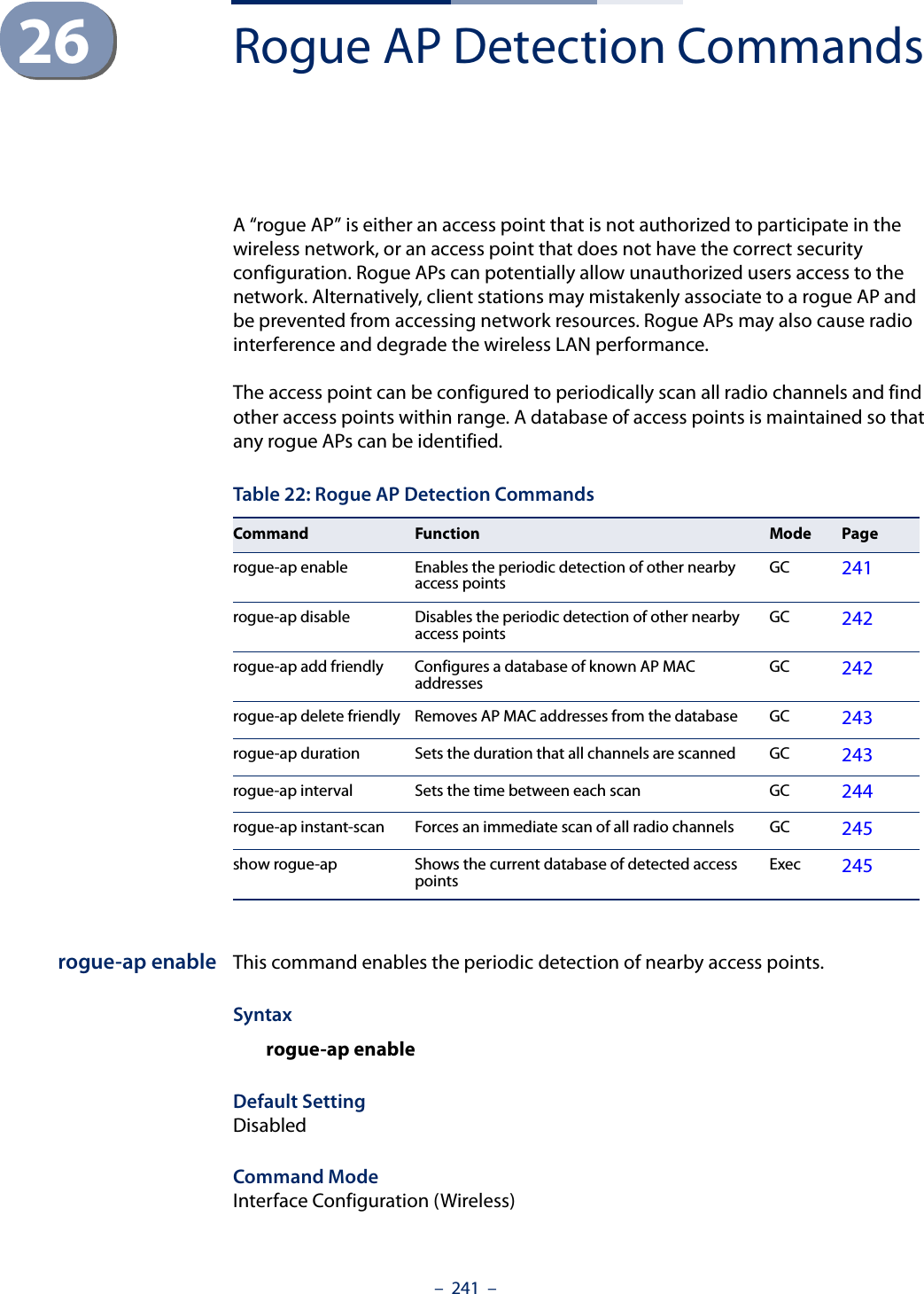
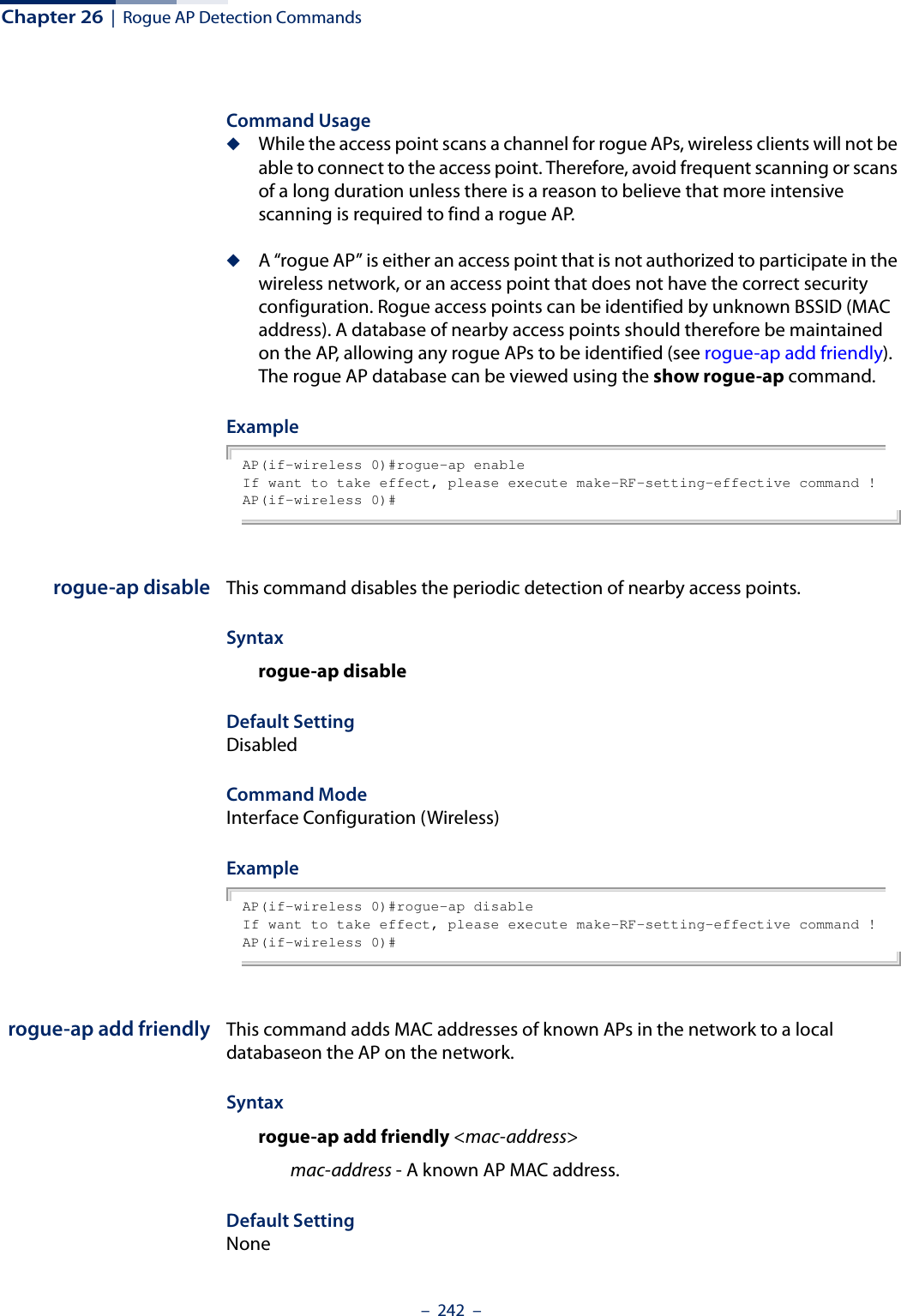
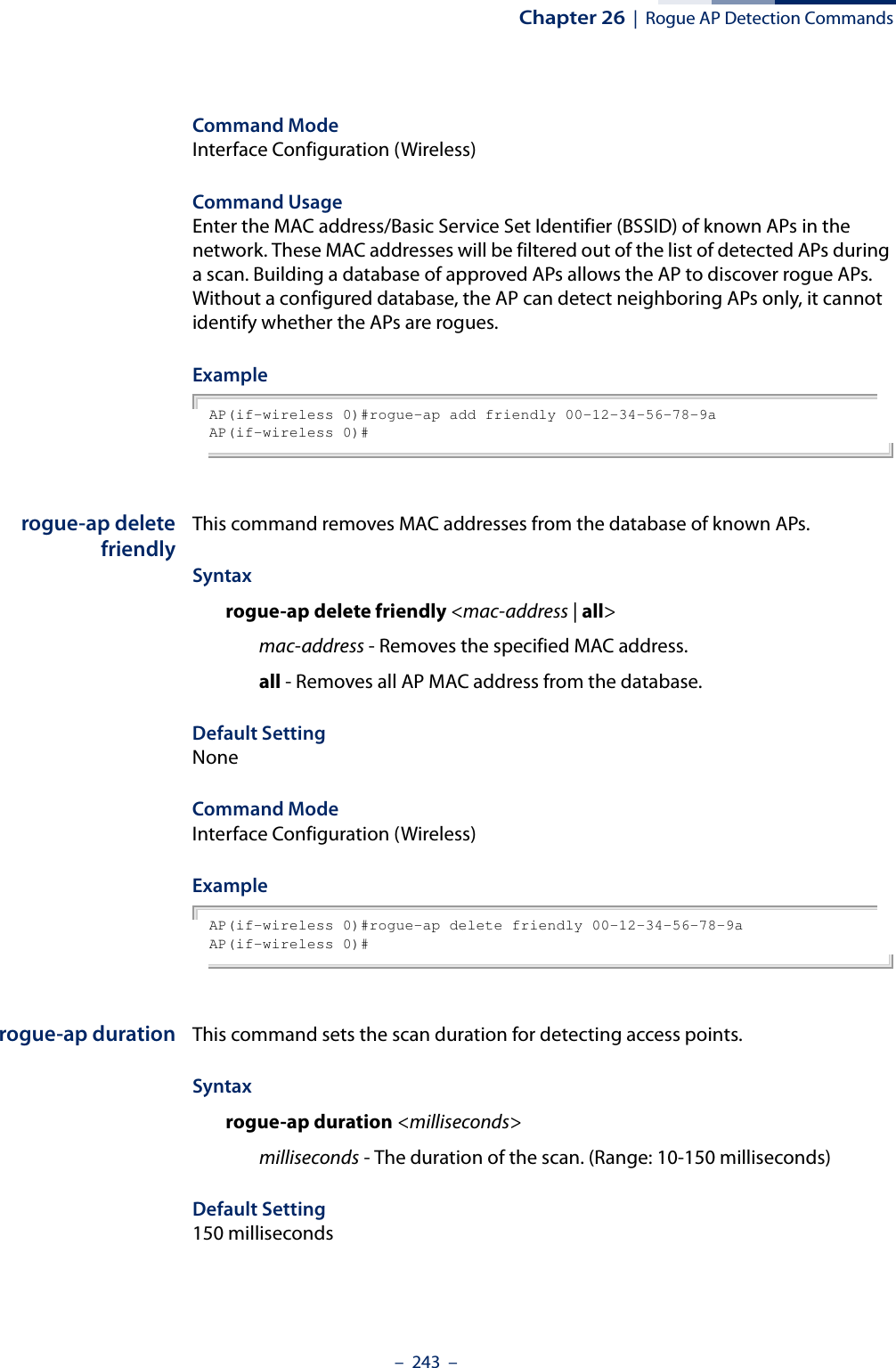
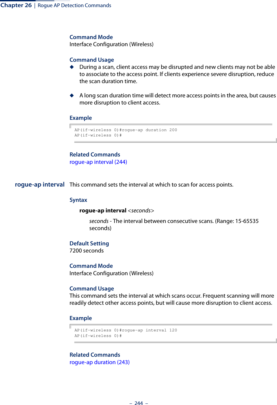
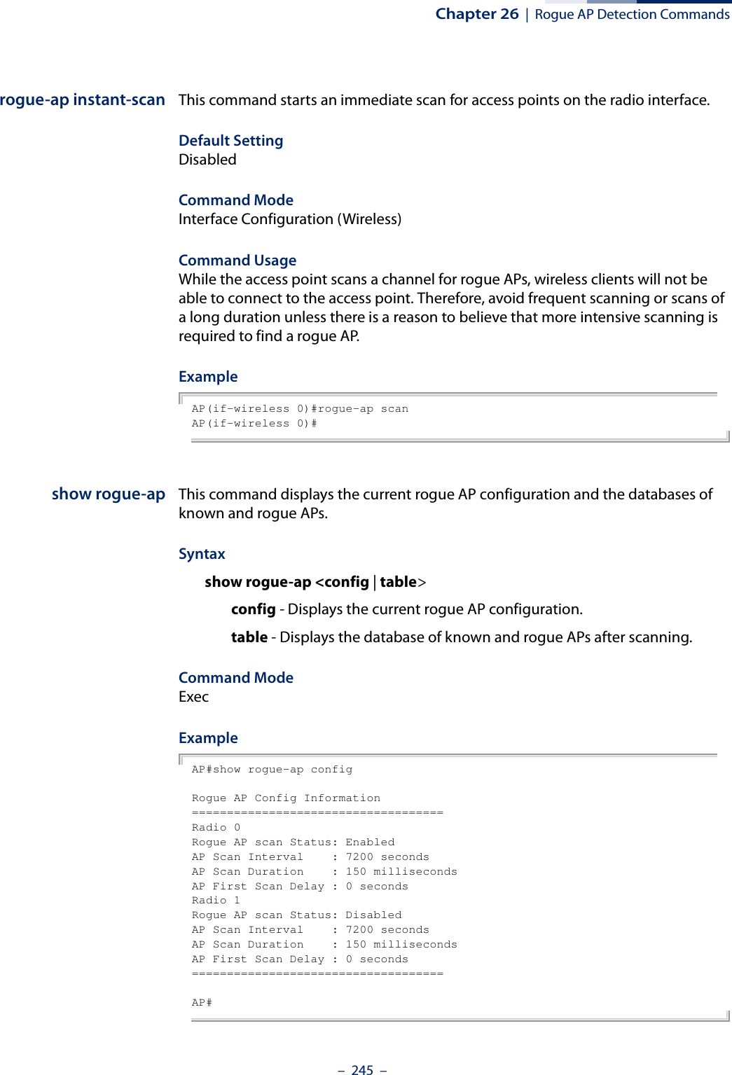
![– 247 –27 Link Integrity CommandsThe access point provides a link integrity feature that can be used to ensure that wireless clients are connected to resources on the wired network. The access point does this by periodically sending Ping messages to a host device in the wired Ethernet network. If the access point detects that the connection to the host has failed, it disables the radio interfaces, forcing clients to find and associate with another access point. When the connection to the host is restored, the access point re-enables the radio interfaces.link-integrity This command enables link integrity detection and configures the IP address, detect interval, response timeout, and retry count for the link integrity host test. Use the no form to disable link integrity detection.Syntaxlink-integrity [<ip_address> interval <interval> timeout <timeout> retry <retry>]no link-integrityip_address - IP address of the host. interval - The interval time between each Ping sent to the host. (Range: 10-86400 seconds)timeout - The time to wait for a response to a Ping message. (Range: 1-10 seconds)retry - The number of consecutive failed Ping counts before the link is determined as lost. (Range: 1-99)Default SettingStatus: DisabledHost IP Address: 192.168.2.254Detect Interval: 60 secondsTable 23: Link Integrity CommandsCommand Function Mode Pagelink-integrity Enables link integrity detection and specifies the IP address of a host device in the wired networkGC 247link-integrity link-fail-action Sets the link fail action GC 248show link-integrity Displays the current link integrity configuration Exec 249](https://usermanual.wiki/Edgecore-Networks/SMC2891WAN.User-Manual-MG/User-Guide-1903199-Page-247.png)
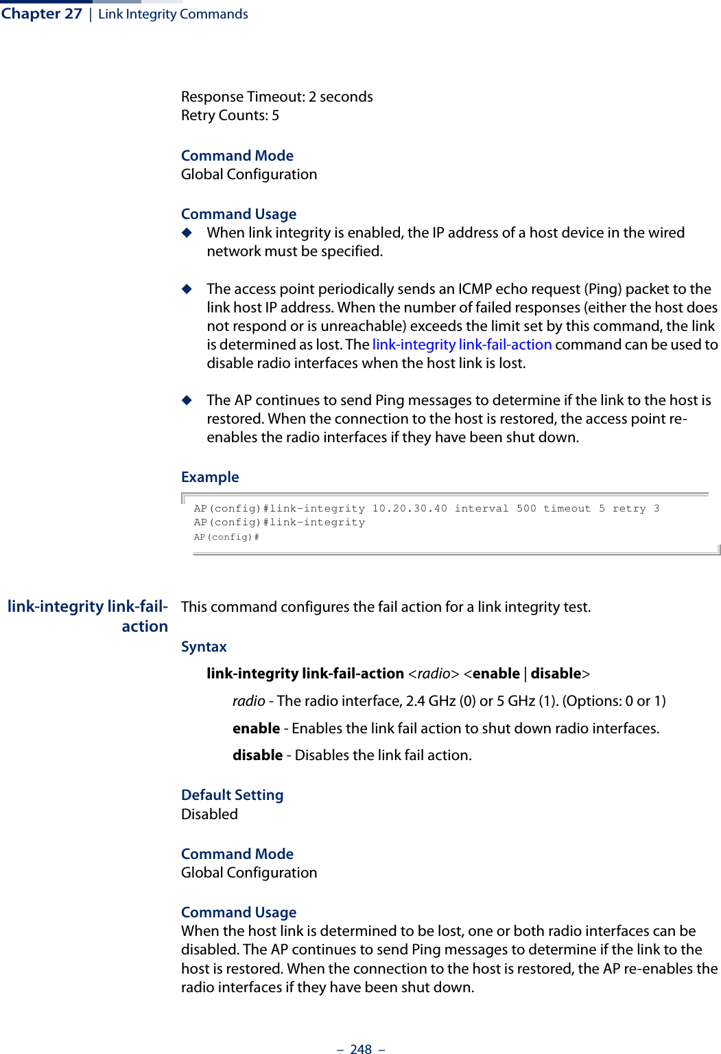
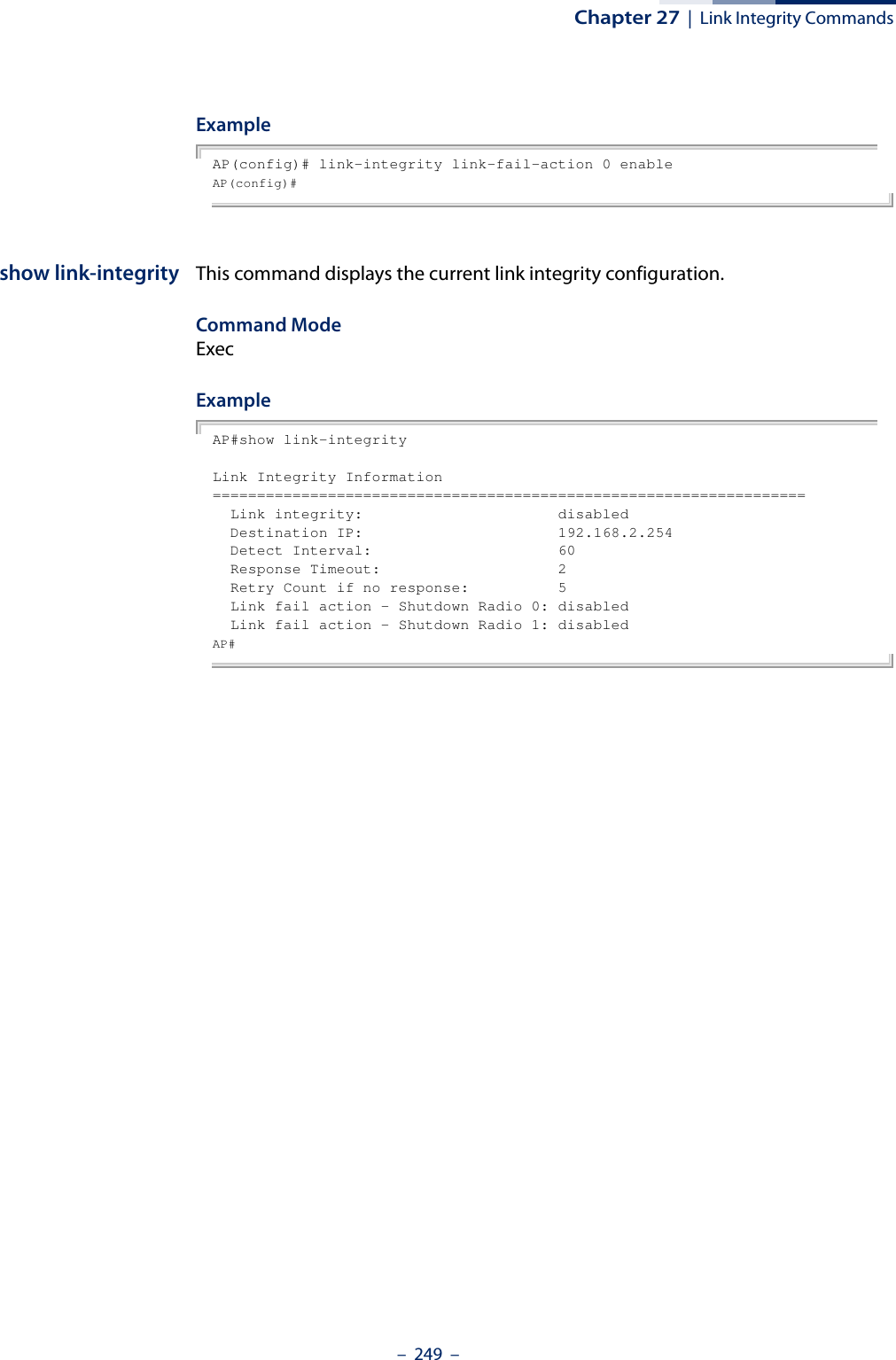
![– 250 –28 Link Layer Discovery CommandsLLDP allows devices in the local broadcast domain to share information about themselves. LLDP-capable devices periodically transmit information in messages called Type Length Value (TLV) fields to neighbor devices. Advertised information is represented in Type Length Value (TLV) format according to the IEEE 802.1ab standard, and can include details such as device identification, capabilities and configuration settings.This information can be used by SNMP applications to simplify troubleshooting, enhance network management, and maintain an accurate network topology.lldp service This command enables LLDP on the access point. Use the no form to disable LLDP.Syntax[no] lldp serviceDefault SettingEnabledCommand Mode Global ConfigurationExampleAP(config)# lldp serviceAP(config)# Table 24: Link Layer Discovery CommandsCommand Function Mode Pagelldp service Enables the transmission of LLDP information GC 250lldp transmit hold-muliplier Sets the message transmission hold time GC 251lldp transmit interval Sets the message transmission interval time GC 251lldp transmit re-init-delay Sets the reinitial delay time GC 252lldp transmit delay-to-local-change Sets the transmission delay value GC 252show lldp Shows the current LLDP information Exec 253](https://usermanual.wiki/Edgecore-Networks/SMC2891WAN.User-Manual-MG/User-Guide-1903199-Page-250.png)
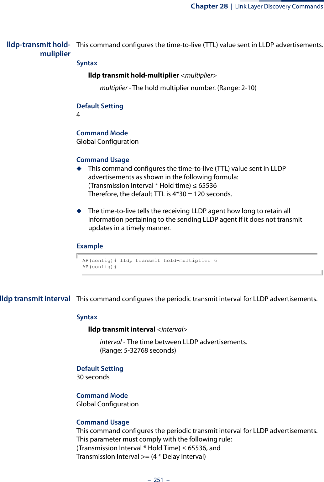
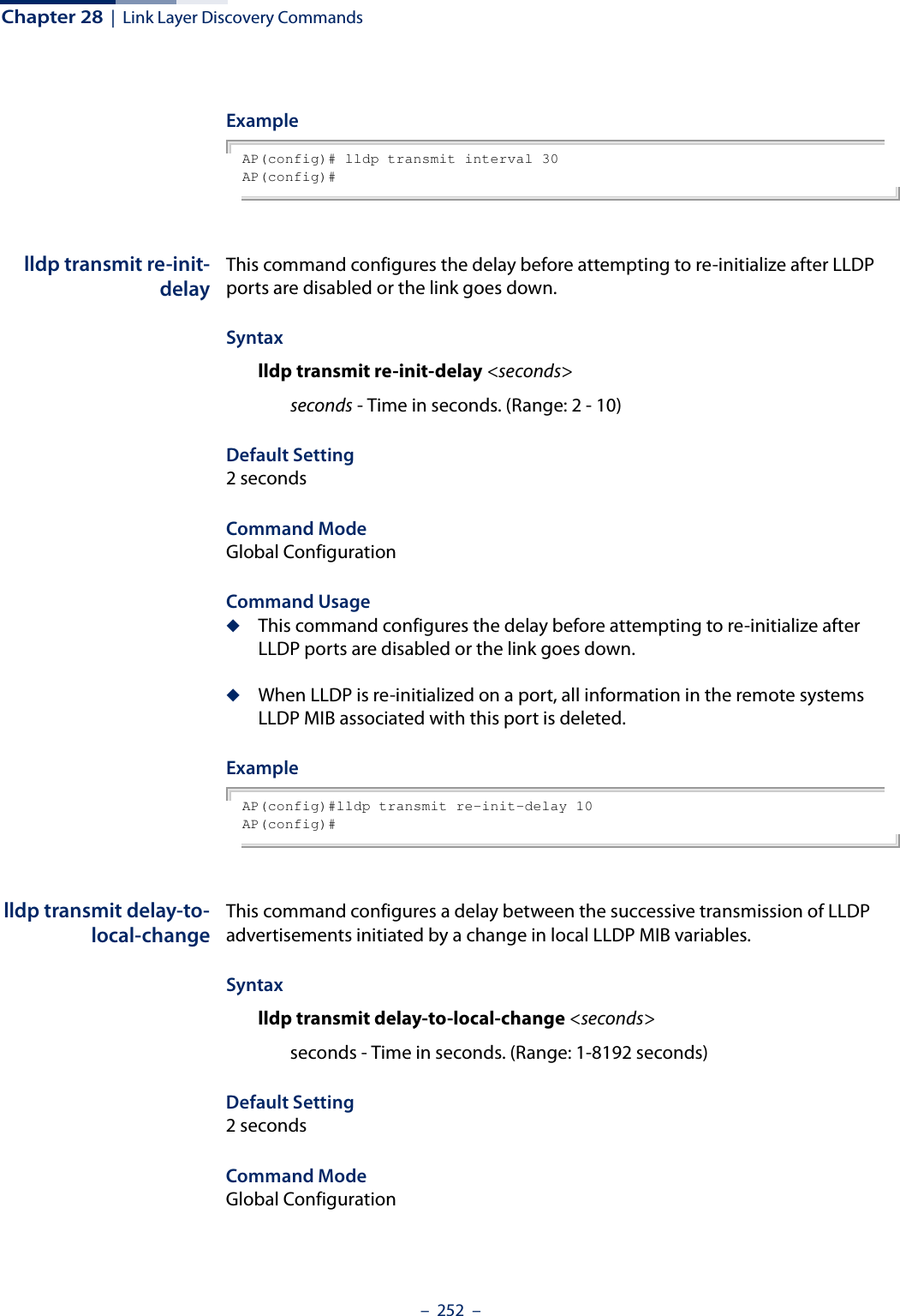
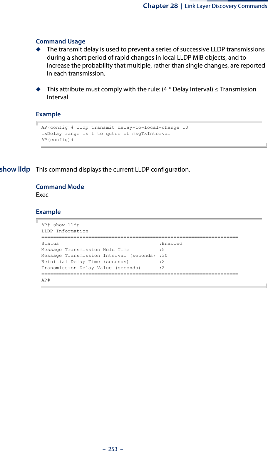
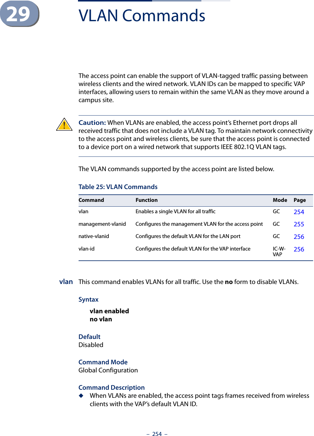
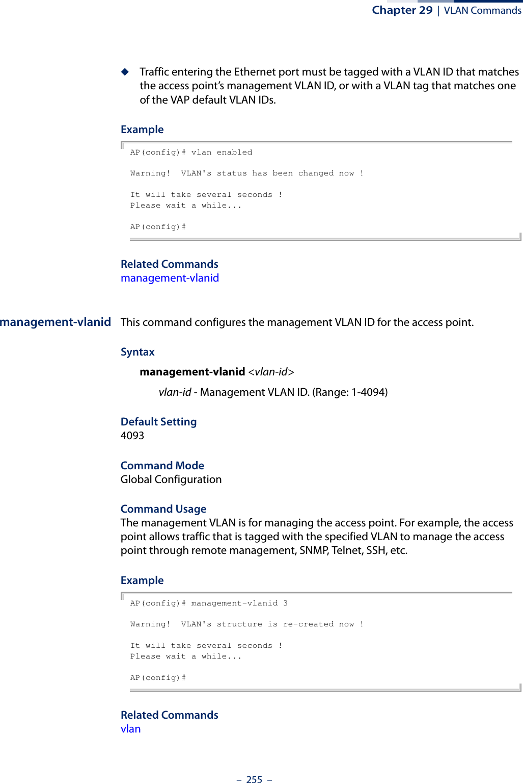
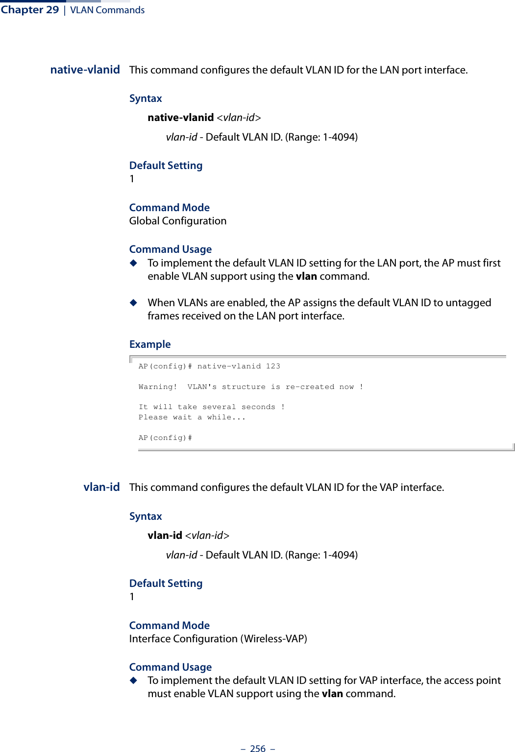
![Chapter 29 | VLAN Commands– 257 –◆When VLANs are enabled, the access point tags frames received from wireless clients with the default VLAN ID for the VAP interface.ExampleAP(if-wireless 0: VAP[0])# vlan-ID 6This setting has not been effective !If want to take effect, please execute make-security-effective command !AP(if-wireless 0: VAP[0])#](https://usermanual.wiki/Edgecore-Networks/SMC2891WAN.User-Manual-MG/User-Guide-1903199-Page-257.png)
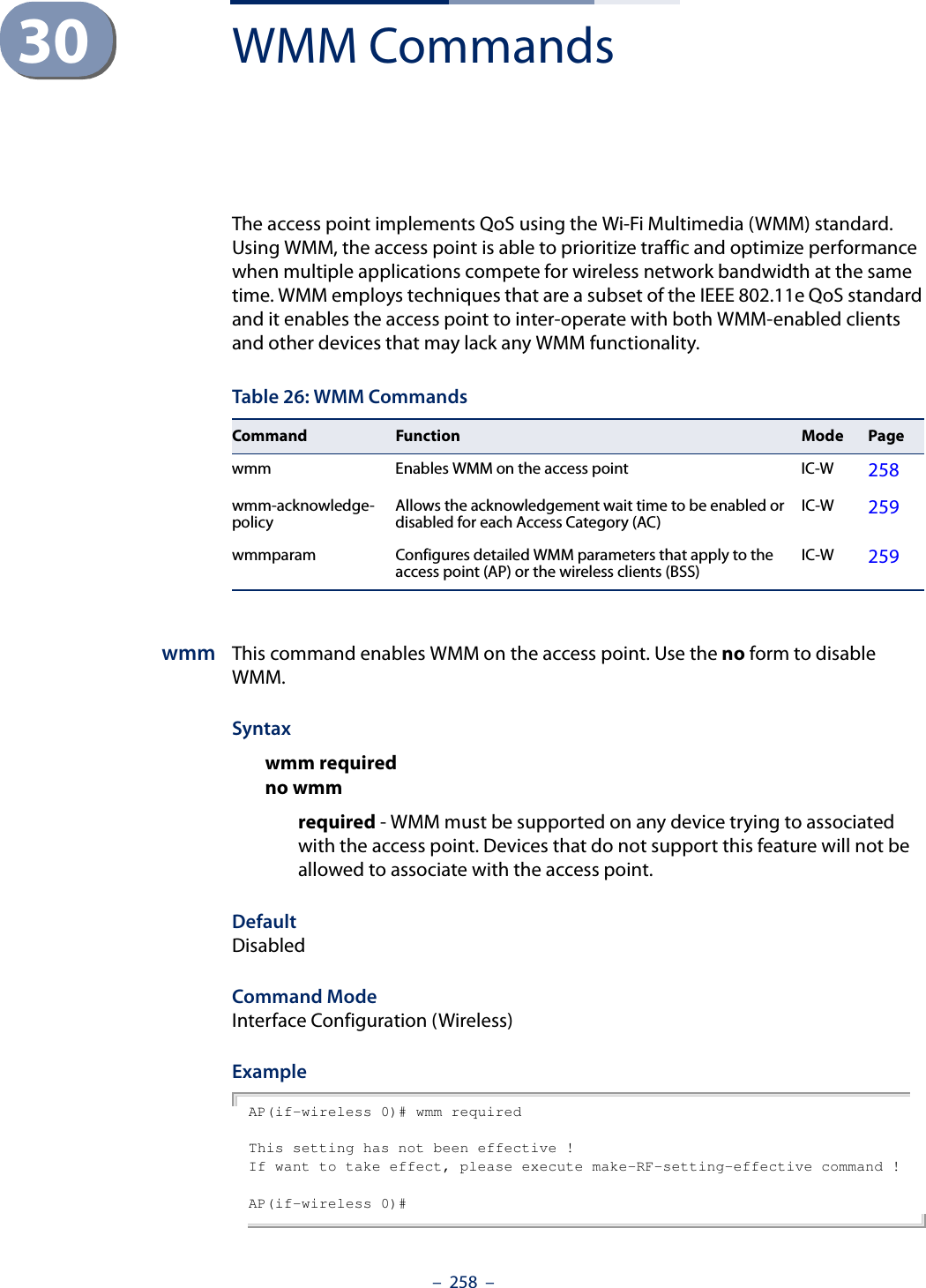
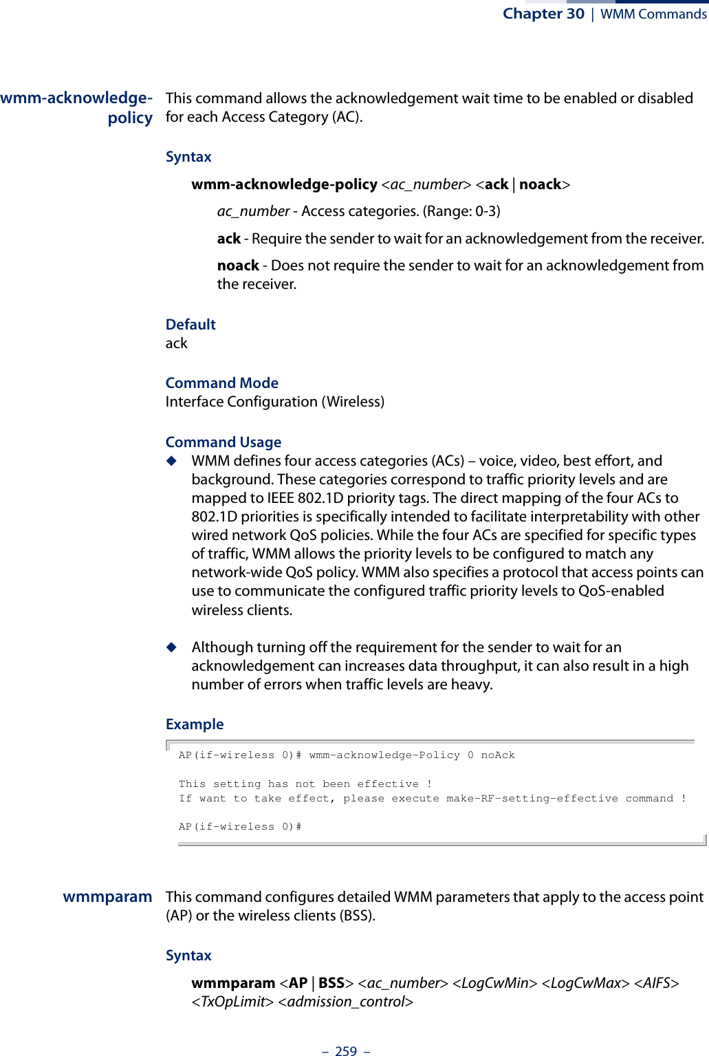
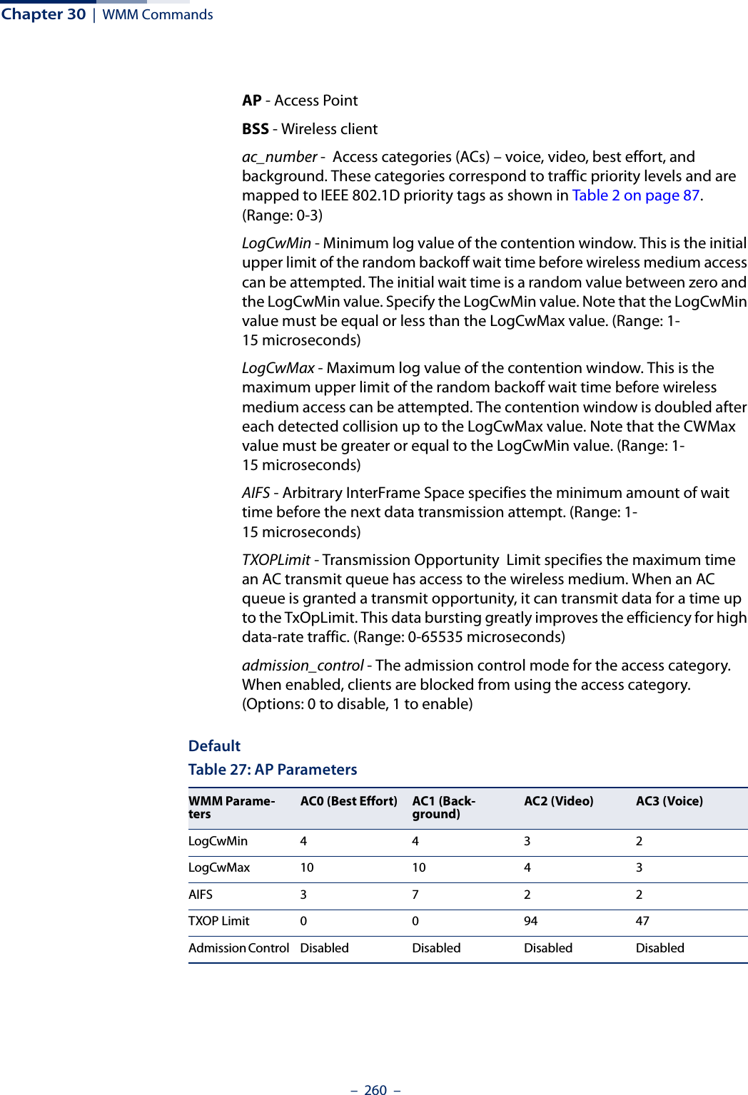
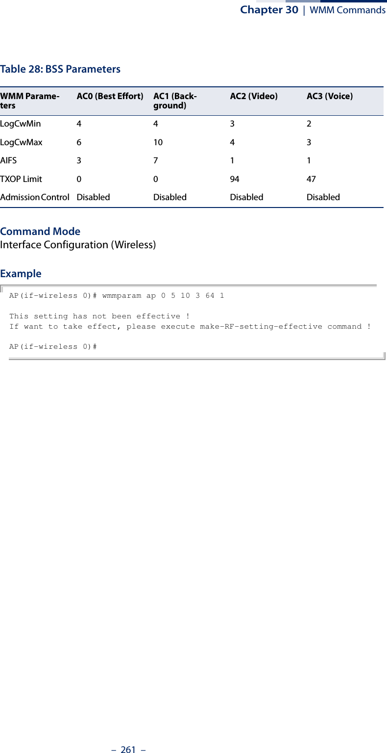

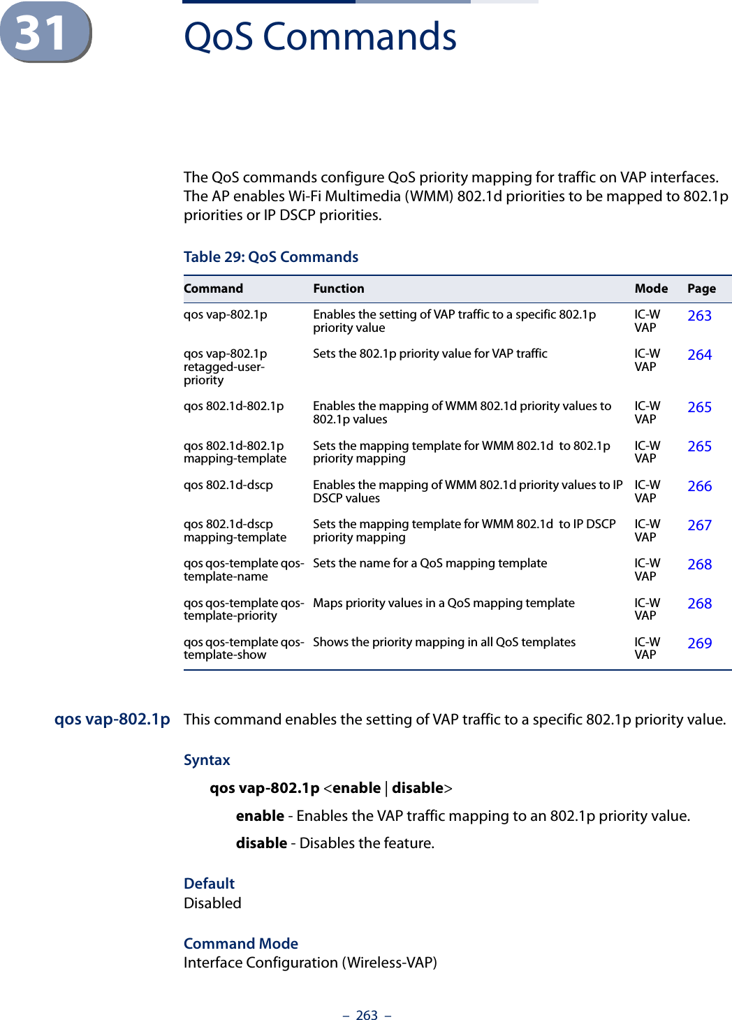
![Chapter 31 | QoS Commands– 264 –Command Usage ◆To implement this command on a VAP interface the default VLAN ID for the VAP must be set to any other value than 1.◆The VAP-to-802.1p priority QoS feature cannot be enabled together with the 802.1d-to-802.1p or 802.1d-to-DSCP features.ExampleAP(if-wireless 0: VAP[0])# qos vap-802.1p enableThis setting has not been effective !If want to take effect, please execute make-security-effective command !AP(if-wireless 0: VAP[0])#qos vap-802.1pretagged-user-priorityThis command sets the 802.1p priority value for all traffic on a VAP interface.Syntaxqos vap-802.1p retagged-user-priority <user-priority>user-priority - The 802.1p priority value for traffic on the VAP interface. Default0Command ModeInterface Configuration (Wireless-VAP)Command Usage ◆Requires the QoS feature be enabled using the qos vap-802.1p command.◆To implement the QoS priority setting on a VAP interface, the default VLAN ID for the VAP must be set to any other value than 1.ExampleAP(if-wireless 0: VAP[0])# qos vap-802.1p retagged-user-priority 7This setting has not been effective !If want to take effect, please execute make-security-effective command !AP(if-wireless 0: VAP[0])#](https://usermanual.wiki/Edgecore-Networks/SMC2891WAN.User-Manual-MG/User-Guide-1903199-Page-264.png)
![Chapter 31 | QoS Commands– 265 –qos 802.1d-802.1p This command enables the mapping of WMM 802.1d priority values to 802.1p values on a VAP interface.Syntaxqos 802.1d-802.1p <enable | disable>enable - Enables the mapping of WMM 802.1d to 802.1p priority values. disable - Disables the feature. DefaultDisabledCommand ModeInterface Configuration (Wireless-VAP)Command Usage ◆This QoS feature requires a QoS mapping template to be configured using the qos qos-template qos-template-priority command. The mapping template can then be linked to the 802.1d-to-802.1p priority mapping using the qos 802.1d-802.1p mapping-template command.◆To implement this command on a VAP interface the default VLAN ID for the VAP must be set to any other value than 1.ExampleAP(if-wireless 0: VAP[0])# qos 802.1d-802.1p enableThis setting has not been effective !If want to take effect, please execute make-security-effective command !AP(if-wireless 0: VAP[0])#qos 802.1d-802.1pmapping-templateThis command sets the mapping template to use for the WMM 802.1d to 802.1p priority mapping on a VAP interface.Syntaxqos 802.1d-802.1p mapping-template <template-id> template-id - The identifying number of a QoS mapping template. (Range: 1-8)Default1Command ModeInterface Configuration (Wireless-VAP)](https://usermanual.wiki/Edgecore-Networks/SMC2891WAN.User-Manual-MG/User-Guide-1903199-Page-265.png)
![Chapter 31 | QoS Commands– 266 –Command Usage ◆The AP supports eight QoS priority mapping templates, each identified by an ID number (1 to 8). The templates also have user-defined name that can be configured using the qos qos-template qos-template-name command.◆The QoS priority mapping templates can be configured using the qos qos-template qos-template-priority command.ExampleAP(if-wireless 0: VAP[0])# qos 802.1d-802.1p mapping-template 3This setting has not been effective !If want to take effect, please execute make-security-effective command !AP(if-wireless 0: VAP[0])#qos 802.1d-dscp This command enables the mapping of WMM 802.1d priority values to IP DSCP values on a VAP interface.Syntaxqos 802.1d-dscp <enable | disable>enable - Enables the mapping of WMM 802.1d to DSCP priority values. disable - Disables the feature. DefaultDisabledCommand ModeInterface Configuration (Wireless-VAP)Command Usage ◆This QoS feature requires a QoS mapping template to be configured using the qos qos-template qos-template-priority command. The mapping template can then be linked to the 802.1d-to-DSCP priority mapping using the qos 802.1d-dscp mapping-template command.◆Both “802.1d to 802.1p” mapping and “802.1d to DSCP” mapping can be enabled simultaneously when the default VLAN ID for the VAP is any other value than 1. When only 802.1d-to-DSCP mapping is enabled, the default VLAN ID for the VAP must be set to 1.ExampleAP(if-wireless 0: VAP[0])# qos 802.1d-dscp enableThis setting has not been effective !If want to take effect, please execute make-security-effective command !](https://usermanual.wiki/Edgecore-Networks/SMC2891WAN.User-Manual-MG/User-Guide-1903199-Page-266.png)
![Chapter 31 | QoS Commands– 267 –AP(if-wireless 0: VAP[0])#qos 802.1d-dscpmapping-templateThis command sets the mapping template to use for the WMM 802.1d to DSCP priority mapping on a VAP interface.Syntaxqos 802.1d-dscp mapping-template <template-id> template-id - The identifying number of a QoS mapping template. (Range: 1-8)Default1Command ModeInterface Configuration (Wireless-VAP)Command Usage ◆The AP supports eight QoS priority mapping templates, each identified by an ID number (1 to 8). The templates also have user-defined name that can be configured using the qos qos-template qos-template-name command.◆The QoS priority mapping templates can be configured using the qos qos-template qos-template-priority command.ExampleAP(if-wireless 0: VAP[0])# qos 802.1d-dscp mapping-template 3This setting has not been effective !If want to take effect, please execute make-security-effective command !AP(if-wireless 0: VAP[0])#](https://usermanual.wiki/Edgecore-Networks/SMC2891WAN.User-Manual-MG/User-Guide-1903199-Page-267.png)
![Chapter 31 | QoS Commands– 268 –qos qos-template qos-template-nameThis command sets the name of a QoS priority mapping template.Syntaxqos qos-template qos-template-name <template-id> <template-name>template-id - The identifying number of a QoS mapping template. (Range: 1-8)template-name - The user-defined name of a QoS mapping template. (Maximum 32 alphanumeric characters; can include “-” and “_”)DefaultID 1: default_up_mapping_1ID 2: default_up_mapping_2ID 3: default_up_mapping_3ID 4: default_up_mapping_4ID 5: default_up_mapping_5ID 6: default_up_mapping_6ID 7: default_up_mapping_7ID 8: default_up_mapping_8Command ModeInterface Configuration (Wireless-VAP)ExampleAP(if-wireless 0: VAP[0])# qos qos-template qos-template-name 3 test-templateAP(if-wireless 0: VAP[0])#qos qos-template qos-template-priorityThis command configures priority values in a QoS priority mapping template.Syntaxqos qos-template qos-template-priority <template-id> <prirority-list>template-id - The identifying number of a QoS mapping template. (Range: 1-8)prirority-list - The mapped priority values a QoS mapping template. (Range: 0-7; the list is enterd as a sequence of eight numbers, for example “01234567”)Default01234567Command ModeInterface Configuration (Wireless-VAP)](https://usermanual.wiki/Edgecore-Networks/SMC2891WAN.User-Manual-MG/User-Guide-1903199-Page-268.png)
![Chapter 31 | QoS Commands– 269 –ExampleAP(if-wireless 0: VAP[0])# qos qos-template qos-template-priority 1 10234765AP(if-wireless 0: VAP[0])#qos qos-template qos-template-showThis command displays the user-defined QoS priority mapping templates and their priority mapping configuration.Syntaxqos qos-template qos-template-show DefaultnoneCommand ModeInterface Configuration (Wireless-VAP)ExampleAP(if-wireless 0: VAP[0])# qos qos-template qos-template-show----------Qos Mapping Template---------------id priority name1 10234765 test-template2 01234567 default_up_mapping_23 01234567 default_up_mapping_34 01234567 default_up_mapping_45 01234567 default_up_mapping_56 01234567 default_up_mapping_67 01234567 default_up_mapping_78 01234567 default_up_mapping_8----------Qos Mapping Template---------------AP(if-wireless 0: VAP[0])#](https://usermanual.wiki/Edgecore-Networks/SMC2891WAN.User-Manual-MG/User-Guide-1903199-Page-269.png)