Edgecore Networks SMC2891WAN 802.11a/b/g/n Outdoor Dual Band Wireless Access Point User Manual user guide
Edgecore Networks Corporation 802.11a/b/g/n Outdoor Dual Band Wireless Access Point user guide
Contents
- 1. User Manual - IG
- 2. User Manual - MG
- 3. User Manual - QSG
- 4. User Manual - Statements
User Manual - MG

802.11a/b/g/n Outdoor
Dual-Band Wireless Access Point
SMC2890W-AN, SMC2891W-AN
MANAGEMENT
GUIDE
802.11a/b/g/n Outdoor Dual Band
Wireless Access Point

No. 1, Creation Road III,
Hsinchu Science Park,
30077, Taiwan, R.O.C.
Tel: +886 3 5638888
Fax: +886 3 6686111
Outdoor Access Point
Management Guide
January 2013
Pub. # 149100000208A
E012013-CS-R01
Information furnished by SMC Networks, Inc. (SMC) is believed to be accurate and reliable. However, no
responsibility is assumed by SMC for its use, nor for any infringements of patents or other rights of third parties
which may result from its use. No license is granted by implication or otherwise under any patent or patent
rights of SMC. SMC reserves the right to change specifications at any time without notice.
Copyright © 2013 by
SMC Networks, Inc.
No. 1 Creation Road III,
Hsinchu Science Park,
30077, Taiwan, R.O.C.
All rights reserved
Trademarks:
SMC is a registered trademark; and Barricade, EZ Switch, TigerStack, TigerSwitch, and TigerAccess are
trademarks of SMC Networks, Inc. Other product and company names are trademarks or registered trademarks
of their respective holders.

– 4 –
Warranty and Product
Registration
To register SMC products and to review the detailed warranty statement, please
refer to the Support Section of the SMC Website at http://www.smc.com.

– 5 –
How to Use This Guide
This guide includes detailed information on the access point (AP) software,
including how to operate and use the management functions of the AP. To deploy
this AP effectively and ensure trouble-free operation, you should first read the
relevant sections in this guide so that you are familiar with all its software features.
Who Should Read This
Guide?
This guide is for network administrators who are responsible for operating and
maintaining network equipment. The guide assumes a basic working knowledge of
LANs (Local Area Networks), the Internet Protocol (IP), and Simple Network
Management Protocol (SNMP).
How This Guide is
Organized
The organization of this guide is based on the AP’s main management interfaces.
The web management interface and command line interface (CLI) are described in
separate sections. An introduction and initial configuration information is also
provided.
The guide includes these sections:
◆Section I “Getting Started” — Includes an introduction to AP management and
initial configuration settings.
◆Section II “Web Configuration” — Includes all management options available
through the web interface.
◆Section III “Command Line Interface” — Includes information on how to use the
CLI and details on all CLI commands.
◆Section IV “Appendices” — Includes information on troubleshooting AP
management access.
Related
Documentation
This guide focuses on AP software configuration, it does not cover hardware
installation of the AP. For specific information on how to install the AP, see the
following guide:
Installation Guide
For all safety information and regulatory statements, see the following documents:
Quick Start Guide
Safety and Regulatory Information

How to Use This Guide
– 6 –
Conventions The following conventions are used throughout this guide to show information:
Note:
Emphasizes important information or calls your attention to related features
or instructions.
Caution:
Alerts you to a potential hazard that could cause loss of data, or damage
the system or equipment.
Warning:
Alerts you to a potential hazard that could cause personal injury.
Revision History This section summarizes the changes in each revision of this guide.
January 2013 Revision
This is the first revision of this guide. It is valid for software release v0.3.3.4.

– 7 –
Contents
Warranty and Product Registration 4
How to Use This Guide 5
Contents 7
Figures 12
Tables 14
Section I Getting Started 17
1 Introduction 18
Configuration Options 18
Console Port Connection 19
Console Login 19
Network Connections 20
Connecting to the Web Interface 20
Home Page and Main Menu 21
Common Web Page Buttons 22
2 Initial Configuration 24
CLI Initial Configuration Steps 24
Setting an IP Address 24
Setting a Password 25
Setting the Country Code 25
Web Quick Start 26
Step 1 26
Step 2 28
Step 3 29
Step 4 31

Contents
– 8 –
Section II Web Configuration 32
3 System Settings 33
Administration Settings 34
IPv4 Address 35
IPv6 Address 36
RADIUS Settings 37
Primary and Secondary RADIUS Server Setup 37
RADIUS Accounting 38
System Time 39
SNTP Server Settings 40
Time Zone Setting 40
Daylight Saving Settings 40
VLAN Configuration 40
System Logs 42
Quick Start Wizard 43
System Resource 44
Bridge STP Configuration 45
Spanning Tree Protocol (STP) 45
Bridge Configuration 48
4 Management Settings 49
Remote Management Settings 49
Access Limitation 51
Simple Network Management Protocol 52
SNMP Basic Settings 52
SNMP Trap Settings 54
View Access Control Model 55
SNMPv3 Users 56
SNMPv3 Targets 57
SNMPv3 Notification Filters 58
5 Advanced Settings 60
Local Bridge Filter 60

Contents
– 9 –
Link Layer Discovery Protocol 61
Access Control Lists 63
Source Address Settings 63
Destination Address Settings 64
Ethernet Type 65
Link Integrity 66
6 Wireless Settings 67
Authentication 68
Local MAC Authentication 68
RADIUS MAC Authentication 69
Radio Settings 71
Virtual Access Points (VAPs) 75
VAP Basic Settings 76
WDS-STA Mode 78
Wireless Security Settings 78
Wired Equivalent Privacy (WEP) 80
VAP QoS Settings 82
VAP Bandwidth Settings 84
Rogue AP Detection 84
Wi-Fi Multimedia (WMM) 86
7 Maintenance Settings 91
Upgrading Firmware 91
Running Configuration 93
Resetting the Access Point 94
Scheduled Reboot 95
8 Status Information 97
AP Status 98
AP System Configuration 98
AP Wireless Configuration 100
Station Status 101
Station Statistics 102
Event Logs 103
WDS Status 104

Contents
– 10 –
Section III Command Line Interface 107
9 Using the Command Line Interface 109
Console Connection 109
Telnet Connection 110
Entering Commands 111
Keywords and Arguments 111
Minimum Abbreviation 111
Command Completion 111
Getting Help on Commands 111
Showing Commands 111
Negating the Effect of Commands 112
Using Command History 112
Understanding Command Modes 112
Command Line Processing 114
10 General Commands 115
11 System Management Commands 119
12 System Logging Commands 139
13 System Clock Commands 144
14 DHCP Relay Commands 149
15 SNMP Commands 151
16 Flash/File Commands 164
17 RADIUS Client Commands 167
18 802.1X Authentication Commands 173
19 MAC Address Authentication Commands 175
20 Filtering Commands 179
21 Spanning Tree Commands 185

Contents
– 11 –
22 WDS Bridge Commands 197
23 Ethernet Interface Commands 199
24 Wireless Interface Commands 206
25 Wireless Security Commands 232
26 Rogue AP Detection Commands 241
27 Link Integrity Commands 247
28 Link Layer Discovery Commands 250
29 VLAN Commands 254
30 WMM Commands 258
31 QoS Commands 263
Section IV Appendices 271
A Troubleshooting 272
Problems Accessing the Management Interface 272
Using System Logs 272
Index of CLI Commands 274
Index 276

– 12 –
Figures
Figure 1: Login Page 21
Figure 2: The Home Page 21
Figure 3: Set Configuration Changes 22
Figure 4: Help Menu 23
Figure 5: Quick Start - Step 1 27
Figure 6: Quick Start - Step 2 28
Figure 7: Quick Start - Step 3 29
Figure 8: Quick Start - Step 4 31
Figure 9: Administration 34
Figure 10: IPv4 Configuration 35
Figure 11: IPv6 Configuration 36
Figure 12: RADIUS Settings 38
Figure 13: SNTP Settings 39
Figure 14: Setting the VLAN Identity 41
Figure 15: System Log Settings 42
Figure 16: System Resource 44
Figure 17: Spanning Tree Protocol 46
Figure 18: Bridge Configuration 48
Figure 19: Remote Management 50
Figure 20: Access Limitation 51
Figure 21: SNMP Basic Settings 53
Figure 22: SNMP Trap Settings 54
Figure 23: SNMP VACM 55
Figure 24: Configuring SNMPv3 Users 56
Figure 25: SNMPv3 Targets 58
Figure 26: SNMP Notification Filter 58
Figure 27: Local Bridge Filter 60
Figure 28: LLDP Settings 61
Figure 29: Source ACLs 63

Figures
– 13 –
Figure 30: Destination ACLs 64
Figure 31: Ethernet Type Filter 65
Figure 32: Link Integrity 66
Figure 33: Local Authentication 68
Figure 34: RADIUS Authentication 69
Figure 35: Radio Settings 71
Figure 36: VAP Settings 75
Figure 37: VAP Basic Settings 76
Figure 38: WDS-STA Mode 78
Figure 39: Configuring VAPs - Security Settings 78
Figure 40: WEP Configuration 81
Figure 41: QoS Settings 82
Figure 42: QoS Template Setting 83
Figure 43: Bandwidth Settings 84
Figure 44: Rogue AP Detection 85
Figure 45: WMM Backoff Wait Times 88
Figure 46: QoS 88
Figure 47: Firmware 92
Figure 48: Running Configuration File 93
Figure 49: Resetting the Access Point 95
Figure 50: Reboot Schedule — Fixed Time 95
Figure 51: Reboot Schedule — Countdown Time 96
Figure 52: AP System Configuration 98
Figure 53: AP Wireless Configuration 100
Figure 54: Station Status 101
Figure 55: Station Statistics 102
Figure 56: Event Logs 103
Figure 57: WDS Status 104

– 14 –
Tables
Table 1: Logging Levels 43
Table 2: WMM Access Categories 87
Table 3: Command Modes 113
Table 4: General Commands 115
Table 5: System Management Commands 119
Table 6: Country Codes 120
Table 7: System Management Commands 139
Table 8: Logging Levels 141
Table 9: System Clock Commands 144
Table 10: DHCP Relay Commands 149
Table 11: SNMP Commands 151
Table 12: Flash/File Commands 164
Table 13: RADIUS Client Commands 167
Table 14: 802.1x Authentication 173
Table 15: MAC Address Authentication 175
Table 16: Filtering Commands 179
Table 17: Spanning Tree Commands 185
Table 18: WDS Bridge Commands 197
Table 19: Ethernet Interface Commands 199
Table 20: Wireless Interface Commands 206
Table 21: Wireless Security Commands 232
Table 22: Rogue AP Detection Commands 241
Table 23: Link Integrity Commands 247
Table 24: Link Layer Discovery Commands 250
Table 25: VLAN Commands 254
Table 26: WMM Commands 258
Table 27: AP Parameters 260
Table 28: BSS Parameters 261
Table 29: QoS Commands 263


Tables
– 16 –

– 17 –
Section I
Getting Started
This section provides an overview of the access point, and introduces some basic
concepts about wireless networking. It also describes the basic settings required to
access the management interface.
This section includes these chapters:
◆“Introduction” on page 18
◆“Initial Configuration” on page 24

– 18 –
1Introduction
The access point (AP) runs software that includes a network management agent.
The agent offers a variety of management options, including SNMP and a web-
based interface. A PC may also be connected directly to the AP’s console port for
configuration using a command line interface (CLI).
Configuration Options
The AP’s HTTP web agent allows you to configure AP parameters, monitor wireless
connections, and display statistics using a standard web browser such as Internet
Explorer 6.x or above, and Mozilla Firefox 3.6.2/4/5. The AP’s web management
interface can be accessed from any computer attached to the network.
The CLI program can be accessed by a direct connection to the RS-232 serial
console port on the AP, or remotely by a Telnet or Secure Shell (SSH) connection
over the network.
The AP’s management agent also supports SNMP (Simple Network Management
Protocol). This SNMP agent permits the AP to be managed from any computer in
the network using network management software.
The AP’s web interface, console interface, and SNMP agent allow you to perform
management functions such as:
◆Set management access user names and passwords
◆Configure IP settings
◆Configure SNMP parameters
◆Configure 2.4 GHz and 5 GHz radio settings
◆Control access through wireless security settings
◆Filter packets using Access Control Lists (ACLs)
◆Upload and download system firmware or configuration files
◆Display system information and statistics

Chapter 1
| Introduction
Console Port Connection
– 19 –
Console Port Connection
The AP provides an RS-232 serial console port that enables a connection to a PC or
terminal for monitoring and configuring the AP. A null-modem console cable is
provided with the AP.
Attach a VT100-compatible terminal, or a PC running a terminal emulation program
to the AP. You can use the console cable provided with this package, or use a null-
modem cable that complies with the wiring assignments shown in the Installation
Guide.
To connect a terminal to the console port, complete the following steps:
1. Connect the console cable to the serial port on a terminal, or a PC running
terminal emulation software, and tighten the captive retaining screws on the
DB-9 connector.
2. Connect the other end of the cable to the console port on the AP.
3. Make sure the terminal emulation software is set as follows:
■Select the appropriate serial port (COM port 1 or COM port 2).
■Set the baud rate to 115200 bps.
■Set the data format to 8 data bits, 1 stop bit, and no parity.
■Set flow control to none.
■Set the emulation mode to VT100.
■When using HyperTerminal, select Terminal keys, not Windows keys.
Note:
Once you have set up the terminal correctly, the console login screen will be
displayed.
For a description of how to use the CLI, see “Using the Command Line Interface” on
page 109. For a list of all the CLI commands, refer to “Index of CLI Commands” on
page 274.
Console Login Access to the CLI is controlled by user names and passwords. The AP has a default
user name and password. To log into the CLI using the default user name and
password, perform these steps:
1. To initiate your console connection, press <Enter>. The “User Access
Verification” procedure starts.

Chapter 1
| Introduction
Network Connections
– 20 –
2. At the login prompt, enter “admin.”
3. At the Password prompt, press <Enter>. There is no default password.
4. The session is opened and the CLI displays the “Accton#” prompt indicating you
have access to the CLI commands.
Example
(none) login: admin
Password:
Jan 1 11:33:13 login[1918]: root login on 'ttyS0'
SMC#
Network Connections
Prior to accessing the AP’s management agent through a network connection, you
must first configure it with a valid IP address, subnet mask, and default gateway
using a console connection, or the DHCP protocol.
The AP has a static default management IPv4 address of 192.168.1.10 and a subnet
mask of 255.255.255.0.
Once the AP’s IP settings are configured for the network, you can access the AP’s
management agent from anywhere within the attached network. The
management agent can be accessed using Telnet from any computer attached to
the network. The AP can also be managed by any computer using a web browser,
or from a network computer using SNMP network management software.
Connecting to the Web Interface
The AP offers a user-friendly web-based management interface for the
configuration of all the unit’s features. Any PC directly attached to the unit can
access the management interface using a web browser, such as Internet Explorer
(version 6.x or above) or Firefox (version 2.x or above).
You may want to make initial configuration changes by connecting a PC directly to
the AP’s LAN port. The AP has a default management IP address of 192.168.1.10 and
a subnet mask of 255.255.255.0. You must set your PC IP address to be on the same
subnet as the AP (that is, the PC and AP addresses must both start 192.168.1.x).
To access the AP’s web management interface, follow these steps:
1. Use your web browser to connect to the management interface using the
default IP address of 192.168.1.10.
Chapter 1
| Introduction
Connecting to the Web Interface
– 21 –
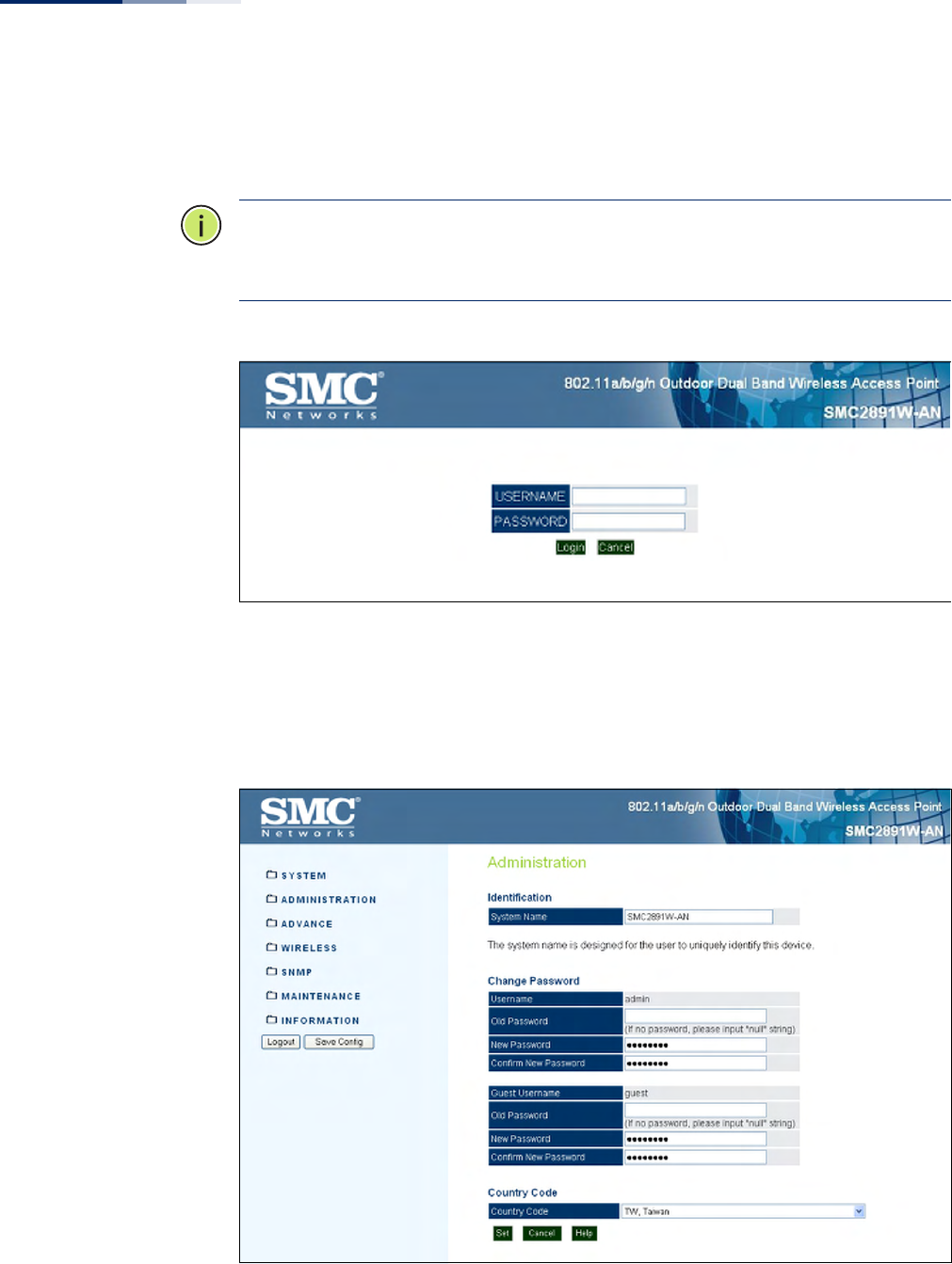
2. Log into the interface by entering the default username “admin” with no
password, then click Login.
Note:
It is strongly recommended to change the default user name and password
the first time you access the web interface. For information on changing user
names and passwords, See “Administration Settings” on page 34.
Figure 1: Login Page
Home Page and Main
Menu
After logging in to the web interface, the home page displays. The home page
shows some basic settings for the AP, including Country Code and the
management access password.
Figure 2: The Home Page

Chapter 1
| Introduction
Connecting to the Web Interface
– 22 –
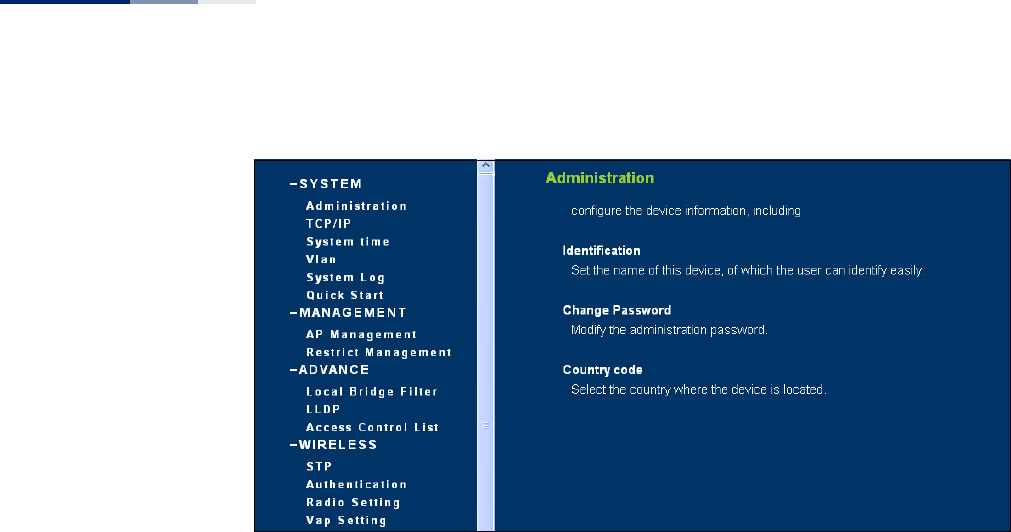
The web interface Main Menu menu provides access to all the configuration
settings available for the AP.
To configure settings, click the relevant Main Menu item. Each Main Menu item is
sumarized below with links to the relevant section in this guide where
configuration parameters are described in detail:
◆System — Configures Management IP, WAN, LAN and QoS settings. See
“System Settings” on page 33.
◆Administration — Configures HTTP, Telnet, and SSH access settings. See
“Management Settings” on page 49.
◆Advanced — Confiures LLDP and Access Control Lists. See “Advanced Settings”
on page 60.
◆Wireless — Configures AP radio settings. See “Wireless Settings” on page 67.
◆SNMP — Configures SNMP settings. See “Management Settings” on page 49.
◆Maintentance — Enables firmware upgrades and resets the AP. See
“Maintenance Settings” on page 91.
◆Information — Displays current system settings. See “Status Information” on
page 97.
Common Web Page
Buttons
The list below describes the common buttons found on most web management
pages:
◆Set – Applies the new parameters and saves them to temporary RAM memory.
Also displays a screen to inform you when it has taken affect. Clicking ‘OK’
returns to the home page. The running configuration will not be saved upon a
reboot unless you use the “Save Config” button.
Figure 3: Set Configuration Changes
◆Cancel – Cancels the newly entered settings and restores the originals.
◆Help – Displays the help window.
Chapter 1
| Introduction
Connecting to the Web Interface
– 23 –
Figure 4: Help Menu
◆Logout – Ends the web management session.
◆Save Config – Saves the current configuration so that it is retained after a
restart.

– 24 –
2Initial Configuration
The AP’s initial configuration steps can be made through the CLI or web browser
interface. If the AP is not configured with an IP address that is compatible with your
network. You can first use the command line interface (CLI) as described below to
configure a valid IP address.
CLI Initial Configuration Steps
First connect to the AP’s console port and log in to the CLI, as described in “Console
Port Connection” on page 19. Then proceed with the required configuration.
Setting an IP Address If the default IP address is not compatible with your network or a DHCP server is not
available, the AP’s IP address must be configured manually using the CLI.
Type “configure” to enter configuration mode, then type “interface ethernet” to
access the Ethernet interface-configuration mode.
SMC#configure
SMC(config)#interface ethernet
SMC(config-if)#
First type “no ip dhcp” to disable DHCP client mode. Then type “ip address ip-
address netmask gateway,” where “ip-address” is the access point’s IP address,
“netmask” is the network mask for the network, and “gateway” is the default
gateway router. Check with your system administrator to obtain an IP address that
is compatible with your network.
SMC(if-ethernet)#no ip dhcp
SMC(if-ethernet)#ip address 192.168.2.2 255.255.255.0 192.168.2.254
SMC(if-ethernet)#
After configuring the access point’s IP parameters, you can access the management
interface from anywhere within the attached network. The command line interface
can also be accessed using Telnet from any computer attached to the network.
Note:
Command examples shown later in this manual abbreviate the console
prompt to “AP” for simplicity.

Chapter 2
| Initial Configuration
CLI Initial Configuration Steps
– 25 –
Setting a Password If you are logging in to the CLI for the fist time, you should define management
access passwords for an administrator and guest (used for CLI and web
management), record them, and then keep them in a safe place.
Note:
If you loose your management access passwords, you will need to use the
Reset button on the AP to set the configuration back to factory default values.
Passwords can consist of 5 to 32 alphanumeric characters and are case sensitive. To
prevent unauthorized access to the AP, set the passwords as follows:
Open the console interface to access the CLI prompt. Type “configure” and press
<Enter>. Type “password admin null password,” w here “null” is the default old
password, and “password” is your new password. Press <Enter>.
Example
AP#configure
AP(config)#password admin null tpschris
AP(config)#
Setting the Country
Code
You must set the country code of the AP to be sure that the radios operate
according to permitted local regulations. That is, setting the country code restricts
operation of the AP to the radio channels and transmit power levels permitted for
wireless networks in the specified country.
Caution:
You must set the country code to the country of operation. Setting the
country code ensures that the radios operate within the local regulations specified
for wireless networks.
Note:
The country code selection is for non-US models only and is not available to
all US models. Per FCC regulation, all Wi-Fi products marketed in the US must be
fixed to US operation channels only.
From the CLI prompt, type “country ?” to display the list of country codes. Select the
code for your country, and enter the command again, following by your country
code (for example., “tw” for Taiwan).
Example
AP#country ?
WORD Country code:
AL-ALBANIA, DZ-ALGERIA, AR-ARGENTINA, AM-ARMENIA, AU-AUSTRALIA,
AT-AUSTRIA, AZ-AZERBAIJAN,
BH-BAHRAIN, BY-BELARUS, BE-BELGIUM, BZ-BELIZE, BO-BOLIVIA,

Chapter 2
| Initial Configuration
Web Quick Start
– 26 –
BA-BOSNIA, BR-BRAZIL, BN-BRUNEI_DARUSSALAM, BG-BULGARIA,
CA-CANADA, CL-CHILE, CN-CHINA, CO-COLOMBIA, CR-COSTA_RICA,
HR-CROATIA, CY-CYPRUS, CZ-CZECH_REPUBLIC, DK-DENMARK,
DK-DENMARK, DO-DOMINICAN_REPUBLIC,
EC-ECUADOR, EG-EGYPT, EE-ESTONIA,
FI-FINLAND, FO-FAROE_ISLANDS, FR-FRANCE, F2-FRANCE2,
GE-GEORGIA, DE-GERMANY, GR-GREECE, GT-GUATEMALA,
HK-HONG_KONG, HN-HONDURAS, HU-HUNGARY,
IS-ICELAND, IN-INDIA, ID-INDONESIA, IR-IRAN, IQ-IRAQ, IE-IRELAND,
IL-ISRAEL, IT-ITALY,
JM-JAMAICA, JP0-JAPAN0, JP3-JAPAN3(including 4.9G channels), JO-JORDAN,
KE-KENYA, KZ-KAZAKHSTAN, KP-NORTH KOREA, KR-KOREA_REPUBLIC,
K2-KOREA_REPUBLIC2(including 2.3G channels),
K3-KOREA_REPUBLIC3(more channels in 5G), KW-KUWAIT,
LV-LATVIA, LB-LEBANON, LI-LIECHTENSTEIN, LT-LITHUANIA,
LU-LUXEMBOURG, LY-LIBYA, MO-MACAU,
MO-MACAU, MK-MACEDONIA, MY-MALAYSIA, MT-MALTA, MX-MEXICO,
MC-MONACO, MA-MOROCCO,
NL-NETHERLANDS, AN-NETHERLANDS-ANTELLIS, NZ-NEW_ZEALAND,
NI-NICARGUA, NO-NORWAY,
OM-OMAN,
PK-PAKISTAN, PA-PANAMA, PY-PARAGUAY, PE-PERU, PH-PHILIPPINES,
PL-POLAND, PT-PORTUGAL, PR-PUERTO_RICO,
QA-QATAR,
RO-ROMANIA, RU-RUSSIA,
SA-SAUDI_ARABIA, RS_ME-SERBIA & MONTENEGRO, SG-SINGAPORE, SI-SLOVENIA,
SK-SLOVAK_REPUBLIC, SV-EL SALVADOR, ZA-SOUTH_AFRICA, ES-SPAIN,
LK-SRILANKA, SE-SWEDEN, CH-SWITZERLAND, SY-SYRIA,
TW-TAIWAN, TH-THAILAND, TT-TRINIDAD & TOBAGO, TN-TUNISIA, TR-TURKEY,
AE-UNITED_ARAB_EMIRATES, GB-UNITED_KINGDOM, UA-UKRAINE,
US-UNITED_STATES, PS-UNITED_STATES(PUBLIC SAFETY), UY-URUGUAY,
UZ-UZBEKISTAN,
VE-VENEZUELA, VN-VIETNAM, YE-YEMEN,
ZW-ZIMBABWE
AP# country tw
AP#
Web Quick Start
The web interface Quick Start menu is designed to help you configure the basic
settings required to get the AP up and running.
Click “System’” followed by “Quick Start’”
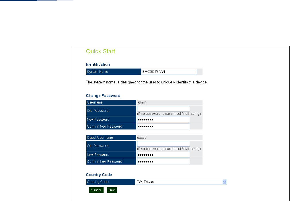
Step 1 The first page of the Quick Start configures the system identification, access
password, and the Country Code.
Chapter 2
| Initial Configuration
Web Quick Start
– 27 –
Figure 5: Quick Start - Step 1
The following items are displayed on the first page of the Quick Start wizard:
Identification
◆System Name — The name assigned to the access point.
(Default: SMC2890W-AN or SMC2891W-AN)
Change Password
◆Username/Guest Username — The name of the user is fixed as either “admin”
or “guest” and is not configurable.
◆Old Password — If the unit has been configured with a password already,
enter that password, otherwise enter the default password “null.”
◆New Password — The password for management access.
(Length: 5-32 characters, case sensitive)
◆Confirm New Password — Enter the password again for verification.
Country Code
◆Country Code — Configures the access point’s country code from a drop down
menu, which identifies the country of operation and sets the authorized radio
channels.
Chapter 2
| Initial Configuration
Web Quick Start
– 28 –
Caution:
You must set the country code to the country of operation. Setting the
country code restricts operation of the access point to the radio channels and
transmit power levels permitted for wireless networks in the specified country.
◆Cancel — Cancels the newly entered settings and restores the orignals.
◆Next — Proceeds to the next page.
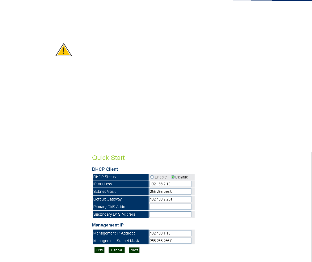
Step 2 The Step 2 page of the Quick Start configures IP settings and DHCP client status.
Figure 6: Quick Start - Step 2
The following items are displayed on this page:
DHCP
◆DHCP Status — Enables/disables DHCP on the access point. (Default: Disabled)
◆IP Address — Specifies an IP address for the access point. Valid IP addresses
consist of four decimal numbers, 0 to 255, separated by periods. (Default:
192.168.2.10.)
◆Subnet Mask — Indicates the local subnet mask. Select the desired mask from
the drop down menu. (Default: 255.255.255.0)
◆Default Gateway — The default gateway is the IP address of the router for the
access point, which is used if the requested destination address is not on the
local subnet. (Default: 192.168.2.254)
If you have DNS, RADIUS, or other network servers located on another subnet,
type the IP address of the default gateway router in the text field provided.
Chapter 2
| Initial Configuration
Web Quick Start
– 29 –
◆Primary and Secondary DNS Address — The IP address of Domain Name
Servers on the network. A DNS maps numerical IP addresses to domain names
and can be used to identify network hosts by familiar names instead of the IP
addresses. (The default Primary and Secondary DNS addresses are null values.)
◆Management IP — The IPv4 address of the AP through which you can access
management interfaces.
■Management IP Address — Specifies an IPv4 address for management of
the access point. (Default: 192.168.1.10.)
■Management Subnet Mask — Indicates the local subnet mask.
(Default: 255.255.255.0)
◆Prev — Returns to the previous screen.
◆Cancel — Cancels the newly entered settings and restores the orignals.
◆Next — Proceeds to the final step in the Quick Start wizard.
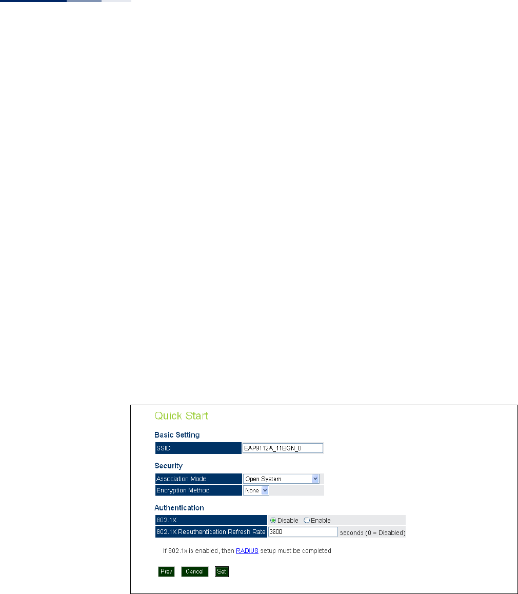
Step 3 The Step 3 page of the Quick Start configures basic radio and wireless security
settings.
Figure 7: Quick Start - Step 3
The following items are displayed on this page:
Basic Setting
◆SSID — The name of the basic service set provided by the primary VAP
interface. Clients that want to connect to the network through the AP must set
their SSID to the same as that of a VAP interface.
(Default: EAP9112A_11BGN_0; Range: 1-32 characters)

Chapter 2
| Initial Configuration
Web Quick Start
– 30 –
Security
◆Association Mode — Defines the mode with which the VAP will associate with
clients. (For more information on security modes, see “Wireless Security
Settings” on page 78.)
■Open System: The VAP is configured by default as an “open system,” which
broadcasts a beacon signal including the configured SSID. Wireless clients
with an SSID setting of “any” can read the SSID from the beacon and
automatically set their SSID to allow immediate connection.
■WPA: WPA employs a combination of several technologies to provide an
enhanced security solution for 802.11 wireless networks.
■WPA-PSK: For enterprise deployment, WPA requires a RADIUS
authentication server to be configured on the wired network. However, for
small office networks that may not have the resources to configure and
maintain a RADIUS server, WPA provides a simple operating mode that uses
just a pre-shared password for network access. The Pre-Shared Key mode
uses a common password for user authentication that is manually entered
on the access point and all wireless clients. The PSK mode uses the same
TKIP packet encryption and key management as WPA in the enterprise,
providing a robust and manageable alternative for small networks.
■WPA2: WPA was introduced as an interim solution for the vulnerability of
WEP pending the ratification of the IEEE 802.11i wireless security standard.
In effect, the WPA security features are a subset of the 802.11i standard.
WPA2 includes the now ratified 802.11i standard, but also offers backward
compatibility with WPA. Therefore, WPA2 includes the same 802.1X and PSK
modes of operation and support for TKIP encryption.
■WPA2-PSK: Clients using WPA2 with a Pre-shared Key are accepted for
authentication.
■WPA-WPA2 Mixed: Clients using WPA or WPA2 are accepted for
authentication.
■WPA-WPA2-PSK-mixed: Clients using WPA or WPA2 with a Pre-shared Key
are accepted for authentication.
◆Encryption Method — Selects an encryption method for the global key used
for multicast and broadcast traffic, which is supported by all wireless clients.
■WEP: WEP is used as the multicast encryption cipher. You should select
WEP only when both WPA and WEP clients are supported.
■TKIP: TKIP is used as the multicast encryption cipher.
■AES-CCMP: AES-CCMP is used as the multicast encryption cipher. AES-
CCMP is the standard encryption cipher required for WPA2.

Chapter 2
| Initial Configuration
Web Quick Start
– 31 –
Authentication
◆802.1X — The access point supports 802.1X authentication only for clients
initiating the 802.1X authentication process (i.e., the access point does not
initiate 802.1X authentication). For clients initiating 802.1X, only those
successfully authenticated are allowed to access the network. For those clients
not initiating 802.1X, access to the network is allowed after successful wireless
association with the access point. The 802.1X mode allows access for clients not
using WPA or WPA2 security.
◆Pre-Authentication — When using WPA2 over 802.1X, pre-authentication can
be enabled, which allows clients to roam to a new access point and be quickly
associated without performing full 802.1X authentication. (Default: Disabled)
◆802.1x Reauthentication Time — The time period after which a connected
client must be re-authenticated. During the re-authentication process of
verifying the client’s credentials on the RADIUS server, the client remains
connected the network. Only if re-authentication fails is network access
blocked. (Range: 0-65535 seconds; Default: 0 means disabled)
Note:
When 802.1X is enabled, be sure to configure RADIUS server details. For
more information, see “RADIUS Settings” on page 37.
Step 4 When you have clicked “Set” after Step 3, the AP saves the Quick Start configuration
settings. Click “OK” to confirm that the Quick Start is complete.
Figure 8: Quick Start - Step 4

– 32 –
Section II
Web Configuration
This section provides details on configuring the access point using the web
browser interface.
This section includes these chapters:
◆“System Settings” on page 33
◆“Management Settings” on page 49
◆“Advanced Settings” on page 60
◆“Wireless Settings” on page 67
◆“Maintenance Settings” on page 91
◆“Status Information” on page 97

– 33 –
3System Settings
This chapter describes basic system settings on the access point. It includes the
following sections:
◆“Administration Settings” on page 34
◆“IPv4 Address” on page 35
◆“IPv6 Address” on page 36
◆“RADIUS Settings” on page 37
◆“System Time” on page 39
◆“VLAN Configuration” on page 40
◆“System Logs” on page 42
◆“Quick Start Wizard” on page 43
◆“System Resource” on page 44
◆“Bridge STP Configuration” on page 45
Chapter 3
| System Settings
Administration Settings
– 34 –
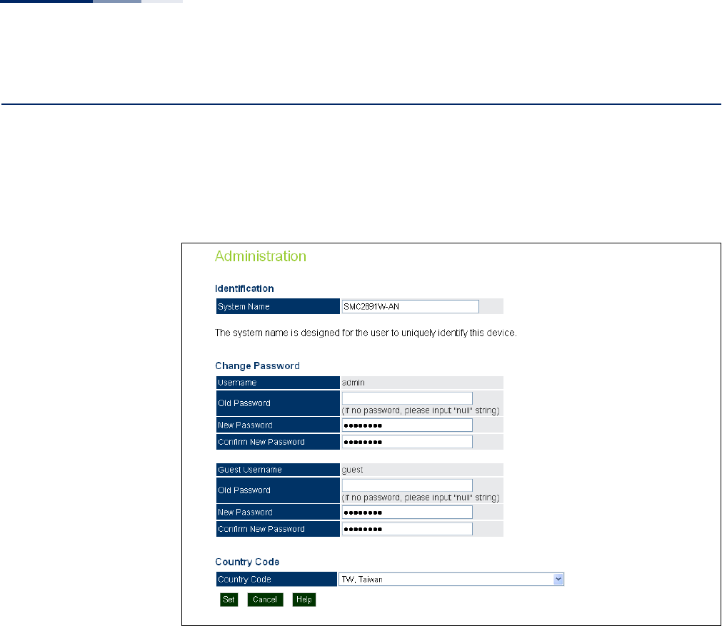
Administration Settings
The Administration Settings page configures some basic settings for the AP, such as
the system identification name, the management access passwords, and the
wireless operation Country Code.
Figure 9: Administration
The following items are displayed on this page:
◆System Name — An alias for the AP, enabling the device to be uniquely
identified on the network. (Default: SMC2890W-AN or SMC2891W-AN;
Range: 1-32 characters)
◆Username/Guest Username — The name of the user is fixed as either “admin”
or “guest” and is not configurable.
◆Old Password — Type your current password.
◆New Password — The password for management access.
(Length: 5-32 characters, case sensitive)
◆Confirm New Password — Enter the password again for verification.
◆Country Code — Configures the AP’s country code, which identifies the
country of operation and sets the authorized radio channels.
Chapter 3
| System Settings
IPv4 Address
– 35 –
Caution:
You must set the country code to the country of operation. Setting the
country code restricts operation of the AP to the radio channels and transmit
power levels permitted for wireless networks in the specified country.
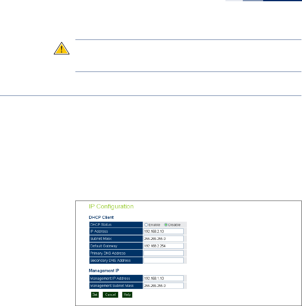
IPv4 Address
Configuring the AP with an IPv4 address expands your ability to manage the AP. A
number of the AP’s features depend on IPv4 addressing to operate.
You can use the web browser interface to access IPv4 addressing only if the access
point already has an IPv4 address that is reachable through your network.
By default, the AP will be not be automatically configured with IPv4 settings from a
Dynamic Host Configuration Protocol (DHCP) server. The default IPv4 address for
management access is 192.168.1.10, with a subnet mask 255.255.255.0.
Figure 10: IPv4 Configuration
The following items are displayed on this page:
◆DHCP Status — Enables/disables DHCP on the access point.
◆IP Address — Specifies an IP address for the access point. Valid IP addresses
consist of four decimal numbers, 0 to 255, separated by periods. (Default:
192.168.2.10.)
◆Subnet Mask — Indicates the local subnet mask. (Default: 255.255.255.0)
◆Default Gateway — The default gateway is the IP address of the router for the
access point, which is used if the requested destination address is not on the
local subnet.

Chapter 3
| System Settings
IPv6 Address
– 36 –
If you have management stations, DNS, RADIUS, or other network servers
located on another subnet, type the IP address of the default gateway router in
the text field provided.
◆Primary and Secondary DNS Address — The IP address of Domain Name
Servers on the network. A DNS maps numerical IP addresses to domain names
and can be used to identify network hosts by familiar names instead of the IP
addresses.
If you have one or more DNS servers located on the local network, type the IP
addresses in the text fields provided.
◆Management IP — The IPv4 address of the AP through which you can access
management interfaces.
■Management IP Address — Specifies an IPv4 address for management of
the access point. (Default: 192.168.1.10.)
■Management Subnet Mask — Indicates the local subnet mask.
(Default: 255.255.255.0)
IPv6 Address
This section describes how to configure an IPv6 interface for management access
over the network. This AP supports both IPv4 and IPv6, and can be managed
through either of these address types.
By default, the AP will be not be automatically configured with IPv6 settings from a
DHCPv6 server. The default IPv6 address is 2001:db8::1, subnet mask 64 and a
default gateway of 2001:db8::2.
Figure 11: IPv6 Configuration
The following items are displayed on this page:

Chapter 3
| System Settings
RADIUS Settings
– 37 –
◆DHCP Status — Enables/disables DHCPv6 on the access point.
◆IP Address — Specifies an IPv6 address for management of the access point.
(Default: 2001:db8::1)
◆Subnet Mask — Indicates the local subnet mask. (Default: 64)
◆Default Gateway — The default gateway is the IPv6 address of the router for
the access point, which is used if the requested destination address is not on
the local subnet.
If you have management stations, DNS, RADIUS, or other network servers
located on another subnet, type the IPv6 address of the default gateway router
in the text field provided.
◆Primary and Secondary DNS Address — The IPv6 address of Domain Name
Servers on the network. A DNS maps numerical IPv6 addresses to domain
names and can be used to identify network hosts by familiar names instead of
the IPv6 addresses.
If you have one or more DNS servers located on the local network, type the IPv6
addresses in the text fields provided.
RADIUS Settings
Remote Authentication Dial-in User Service (RADIUS) is an authentication protocol
that uses software running on a central server to control access to RADIUS-aware
devices on the network. An authentication server contains a database of user
credentials for each user that requires access to the network.
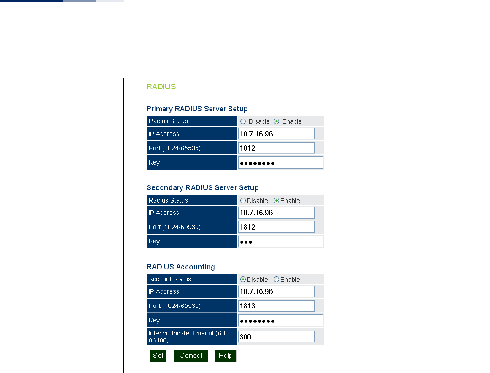
Primary and
Secondary RADIUS
Server Setup
A primary RADIUS server must be specified for the access point to implement IEEE
802.1X network access control and Wi-Fi Protected Access (WPA) wireless security.
A secondary RADIUS server may also be specified as a backup should the primary
server fail or become inaccessible.
In addition, you can configure a RADIUS Accounting server to receive user-session
accounting information from the access point. RADIUS Accounting can be used to
provide valuable information on user activity in the network.
This guide assumes that you have already configured RADIUS server(s) to support
the access point. Configuration of RADIUS server software is beyond the scope of
this guide, refer to the documentation provided with the RADIUS server software.
Chapter 3
| System Settings
RADIUS Settings
– 38 –
Figure 12: RADIUS Settings
The following items are displayed on the RADIUS Settings page:
◆RADIUS Status — Enables/disables the primary RADIUS server.
◆IP Address — Specifies the IP address or host name of the RADIUS server.
◆Port (1024-65535) — The UDP port number used by the RADIUS server for
authentication messages. (Range: 1024-65535; Default: 1812)
◆Key — A shared text string used to encrypt messages between the access point
and the RADIUS server. Be sure that the same text string is specified on the
RADIUS server. Do not use blank spaces in the string. (Maximum length: 255
characters)
RADIUS Accounting The following items are displayed on the RADIUS Settings page:
◆Account Status — Enables/disables RADIUS accounting.
◆IP Address — Specifies the IP address or host name of the RADIUS accounting
server.
Chapter 3
| System Settings
System Time
– 39 –
◆Port (1024-65535) — The UDP port number used by the RADIUS accounting
server for authentication messages. (Range: 1024-65535; Default: 1813)
◆Key — A shared text string used to encrypt messages between the access point
and the RADIUS accounting server. Be sure that the same text string is specified
on the RADIUS server. Do not use blank spaces in the string. (Maximum length:
255 characters)
◆Interim Update Timeout (60-86400) — The interval between transmitting
accounting updates to the RADIUS server. (Range: 60-86400; Default: 300
seconds)
System Time
Simple Network Time Protocol (SNTP) allows the access point to set its internal
clock based on periodic updates from a time server (SNTP or NTP). Maintaining an
accurate time on the access point enables the system log to record meaningful
dates and times for event entries. If the clock is not set, the access point will only
record the time from the factory default set at the last bootup.
The access point acts as an SNTP client, periodically sending time synchronization
requests to specific time servers. You can configure up to two time server IP
addresses. The access point will attempt to poll each server in the configured
sequence.
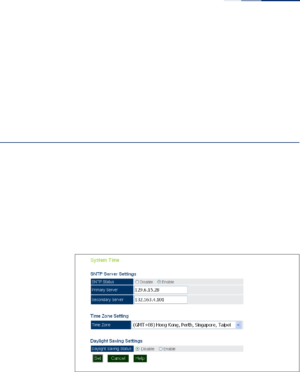
Figure 13: SNTP Settings

Chapter 3
| System Settings
VLAN Configuration
– 40 –
SNTP Server Settings Configures the access point to operate as an SNTP client. When enabled, at least
one time server IP address must be specified.
◆SNTP Status — Enables/disables SNTP. (Default: enabled)
◆Primary Server — The IP address of an SNTP or NTP time server that the access
point attempts to poll for a time update.
◆Secondary Server — The IP address of a secondary SNTP or NTP time server.
The access point first attempts to update the time from the primary server; if
this fails it attempts an update from the secondary server.
Time Zone Setting SNTP uses Greenwich Mean Time, or GMT (sometimes referred to as Coordinated
Universal Time, or UTC) based on the time at the Earth’s prime meridian, zero
degrees longitude. To display a time corresponding to your local time, you must
indicate the number of hours your time zone is located before (east) or after (west)
GMT.
◆Time Zone — Select from the scroll down list the locale you are situated most
close to, for example for New York, select ‘(GMT-05) Eastern Time (US & Canada)’.
Daylight Saving
Settings
The access point provides a way to automatically adjust the system clock for
Daylight Savings Time changes. To use this feature you must define the month and
date to begin and to end the change from standard time. During this period the
system clock is set back by one hour.
◆Daylight Saving Status — Enalbes/disables daylight savings time. (Default:
disabled)
When enabled, set the month, day, and week to start and stop the daylight
savings time.
VLAN Configuration
VLANs (virtual local area networks) are turned off by default when first installing the
access point. If turned on they will automatically tag any packets received by the
LAN port before sending them on to the relevant VAP (virtual access point).
The access point can employ VLAN tagging support to control access to network
resources and increase security. VLANs separate traffic passing between the access
point, associated clients, and the wired network. There can be a default VLAN for
each VAP (Virtual Access Point) interface, and a management VLAN for the access
point.
Chapter 3
| System Settings
VLAN Configuration
– 41 –
Note the following points about the access point’s VLAN support:
◆The management VLAN is for managing the access point through remote
management tools, such as the web interface, SSH, SNMP, or Telnet. The access
point only accepts management traffic that is tagged with the specified
management VLAN ID.
◆All wireless clients associated to the access point are assigned to a VLAN.
Wireless clients are assigned to the default VLAN for the VAP interface with
which they are associated. The access point only allows traffic tagged with
default VLAN IDs to access clients associated on each VAP interface.
◆When VLAN support is enabled on the access point, traffic passed to the wired
network is tagged with the appropriate VLAN ID, either a VAP default VLAN ID,
or the management VLAN ID. Traffic received from the wired network must also
be tagged with one of these known VLAN IDs. Received traffic that has an
unknown VLAN ID or no VLAN tag is dropped.
◆When VLAN support is disabled, the access point does not tag traffic passed to
the wired network and ignores the VLAN tags on any received frames.
Note:
Before enabling VLAN tagging on the access point, be sure to configure the
attached network switch port to support tagged VLAN frames from the access
point’s management VLAN ID and default VLAN IDs. Otherwise, connectivity to the
access point will be lost when you enable the VLAN feature.
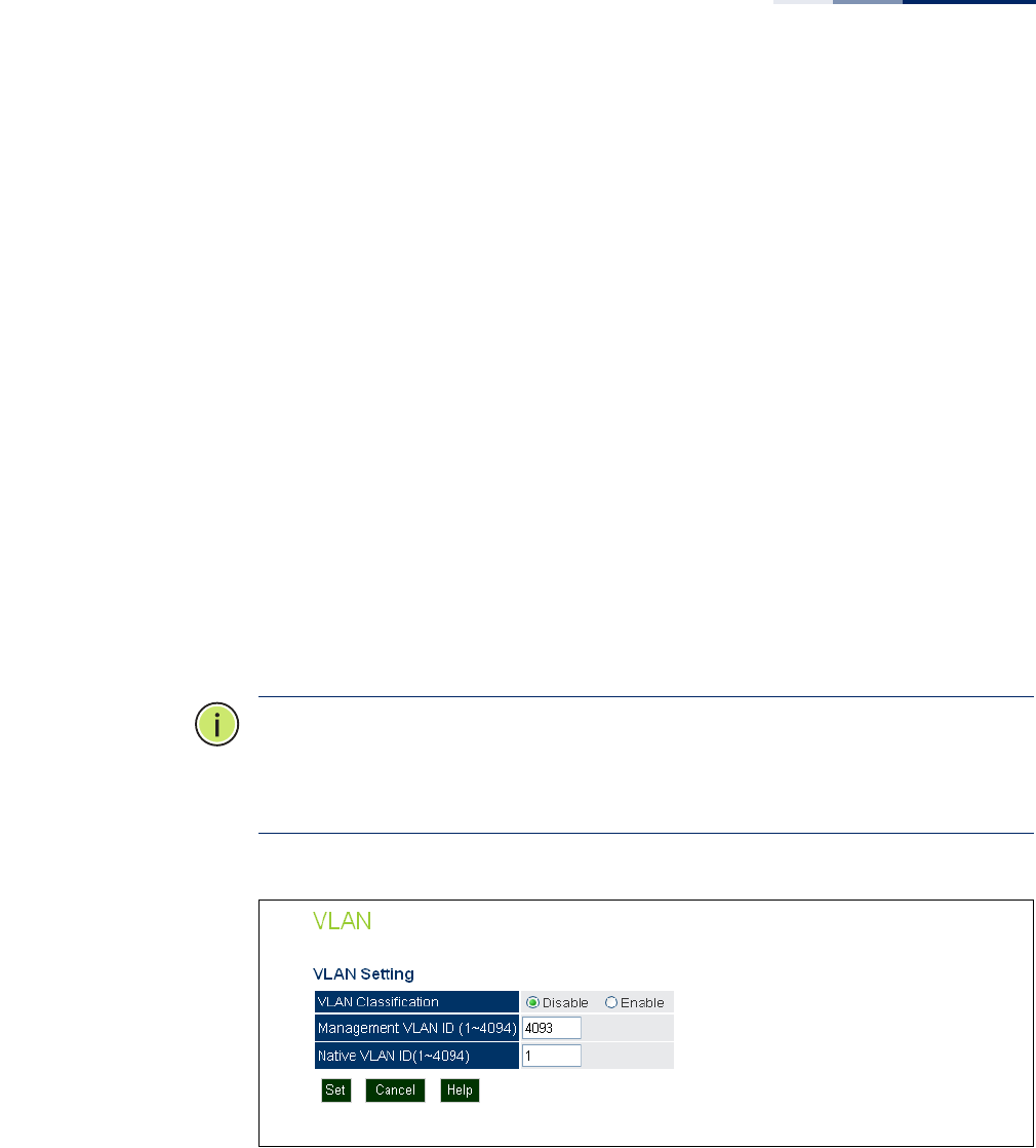
Figure 14: Setting the VLAN Identity
The following items are displayed on this page:
◆VLAN Classification — Enables VLAN packet tagging. (Default: disabled)
◆Management VLAN ID — The VLAN ID that traffic must have to be able to
manage the access point. (Range 1-4094; Default: 4093)
◆Native VLAN ID — The VLAN ID assigned to untagged packets received by the
LAN port. (Range: 1-4094; Default: 1)
Chapter 3
| System Settings
System Logs
– 42 –
System Logs
The access point can be configured to send event and error messages to a System
Log Server. The system clock can also be synchronized with a time server, so that all
the messages sent to the Syslog server are stamped with the correct time and date.
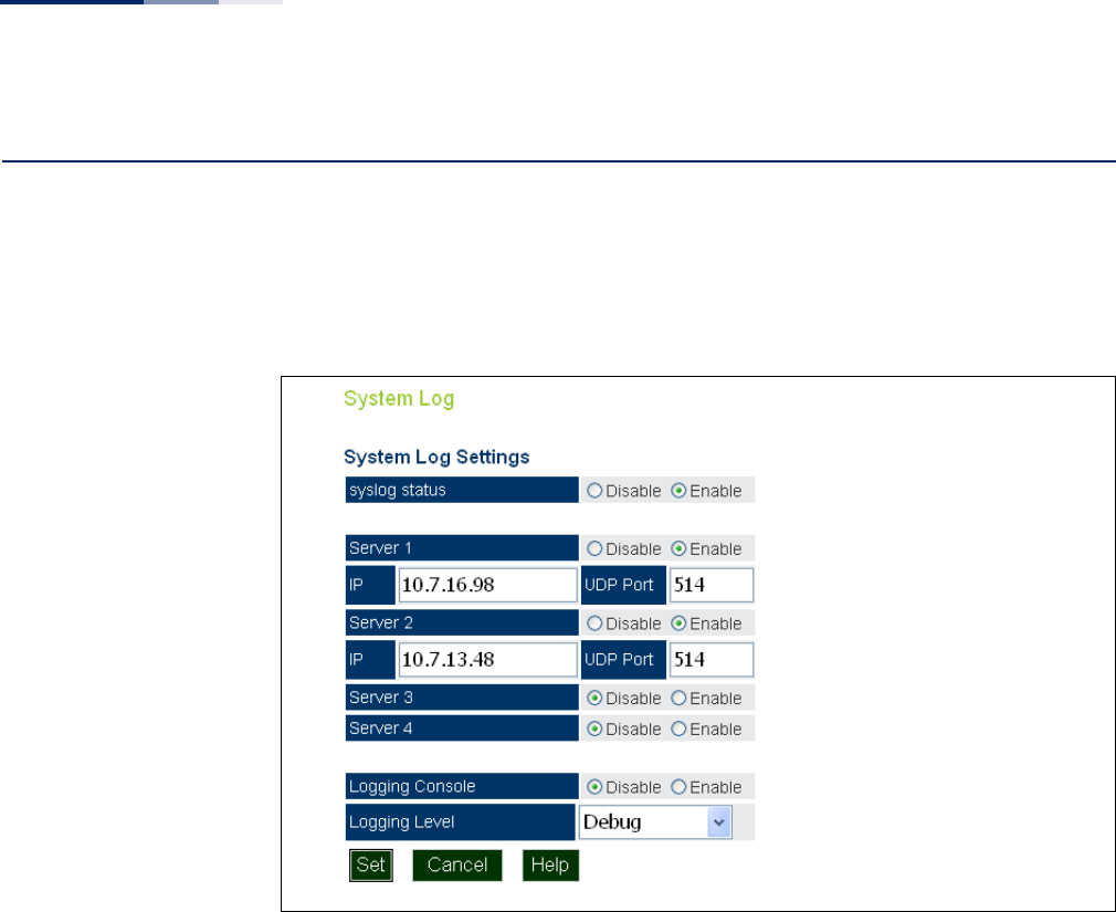
Figure 15: System Log Settings
The following items are displayed on this page:
◆Syslog Status — Enables/disables the logging of error messages. (Default:
enabled)
◆Server 1~4 — Enables the sending of log messages to a Syslog server host. Up
to four Syslog servers are supported on the access point. (Default: disabled)
◆IP — The IP address or name of a Syslog server. (Server 1 Default: 10.7.16.98;
Server 2 Default: 10.7.13.48; Server 3 Default: 10.7.123.123; Server 4 Default:
10.7.13.77)
◆UDP Port — The UDP port used by a Syslog server. (Range: 514 or 11024-
65535; Server 1~2 Default: 514; Server 3 Default: 6553; Server 4 Default: 5432)
◆Logging Console — Enables the logging of error messages to the console.
(Default: disabled)

Chapter 3
| System Settings
Quick Start Wizard
– 43 –
◆Logging Level — Sets the minimum severity level for event logging. (Default:
Debug)
The system allows you to limit the messages that are logged by specifying a
minimum severity level. The following table lists the error message levels from
the most severe (Emergency) to least severe (Debug). The message levels that
are logged include the specified minimum level up to the Emergency level.
Quick Start Wizard
The Quick Start menu item is described in the preceding chapter, see “Web Quick
Start” on page 26.
Table 1: Logging Levels
Error Level Description
Emergency System unusable
Alerts Immediate action needed
Critical Critical conditions (e.g., memory allocation, or free memory error -
resource exhausted)
Error Error conditions (e.g., invalid input, default used)
Warning Warning conditions (e.g., return false, unexpected return)
Notice Normal but significant condition, such as cold start
Informational Informational messages only
Debug Debugging messages
Chapter 3
| System Settings
System Resource
– 44 –
System Resource
The System Resource page displays information on the AP’s current CPU and
memory utilization. This page also allows you to set thresholds for the CPU and
memory usage, where an SNMP trap can be sent as an alert.
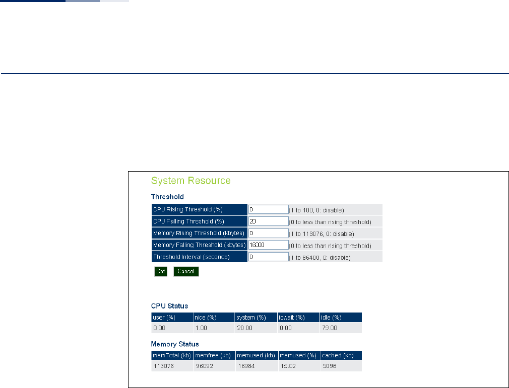
Figure 16: System Resource
The following items are displayed on this page:
◆CPU Rising Threshold — A high CPU utilization percentage above which a
“CPU Busy” SNMP trap message is sent (only sent once). (Range: 1-100 percent,
0 is disabled; Default: 0)
◆CPU Falling Threshold — A low CPU utilization percentage below which a
“CPU Free” SNMP trap message is sent once the Rising Threshold has been
exceeded. (Range: 0 to less than the Rising Threshold; Default: 20)
◆Memory Rising Threshold — A high memory utilization threshold in Kbytes
above which a “Memory Overload” SNMP trap message is sent (only sent once).
(Range: 1-113076 Kbytes, 0 is disabled; Default: 0)
◆Memory Falling Threshold — A low memory utilization threshold in Kbytes
below which a “Memory Free” SNMP trap message is sent once the Rising
Threshold has been exceeded. (Range: 0 to less than the Rising Threshold;
Default: 16000 Kbytes)
◆Threshold Interval — The interval in seconds between each CPU utilization
check. (Range: 1 to 86400 seconds, 0 is disabled; Default: 0)
◆CPU Status — Displays detailed information on the current CPU utilization.

Chapter 3
| System Settings
Bridge STP Configuration
– 45 –
◆Memory Status — Displays detailed information on the current memory
utilization.
Bridge STP Configuration
The Bridge menu enables configuration of the Spanning Tree Protocol (STP) and
the address table aging time.
Spanning Tree
Protocol (STP)
The Spanning Tree Protocol (STP) can be used to detect and disable network loops,
and to provide backup links between switches, bridges or routers. This allows the
wireless bridge to interact with other bridging devices (that is, an STP-compliant
switch, bridge or router) in your network to ensure that only one route exists
between any two stations on the network, and provide backup links which
automatically take over when a primary link goes down.
STP uses a distributed algorithm to select a bridging device (STP-compliant switch,
bridge or router) that serves as the root of the spanning tree network. It selects a
root port on each bridging device (except for the root device) which incurs the
lowest path cost when forwarding a packet from that device to the root device.
Then it selects a designated bridging device from each LAN which incurs the lowest
path cost when forwarding a packet from that LAN to the root device. All ports
connected to designated bridging devices are assigned as designated ports. After
determining the lowest cost spanning tree, it enables all root ports and designated
ports, and disables all other ports. Network packets are therefore only forwarded
between root ports and designated ports, eliminating any possible network loops.
Once a stable network topology has been established, all bridges listen for Hello
BPDUs (Bridge Protocol Data Units) transmitted from the root bridge. If a bridge
does not get a Hello BPDU after a predefined interval (Maximum Age), the bridge
assumes that the link to the root bridge is down. This bridge will then initiate
negotiations with other bridges to reconfigure the network to reestablish a valid
network topology.
Chapter 3
| System Settings
Bridge STP Configuration
– 46 –
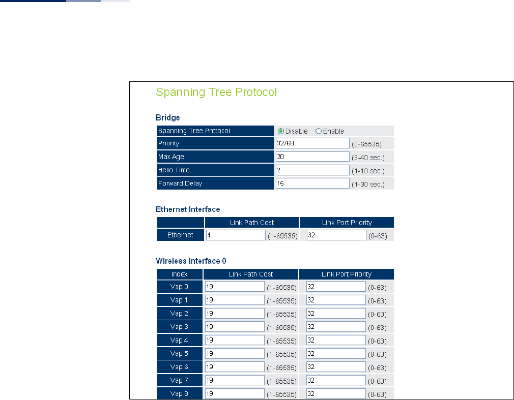
Figure 17: Spanning Tree Protocol
Bridge
Sets STP bridge link parameters.
The following items are displayed on the STP page:
◆Spanning Tree Protcol — Enables/disables STP on the AP.
(Default: Disabled)
◆Priority — Used in selecting the root device, root port, and designated port.
The device with the highest priority becomes the STP root device. However, if
all devices have the same priority, the device with the lowest MAC address will
then become the root device. (Note that lower numeric values indicate higher
priority.) (Default:32768; Range: 0-65535)
◆Max Age — The maximum time (in seconds) a device can wait without
receiving a configuration message before attempting to reconfigure. All device
ports (except for designated ports) should receive configuration messages at
regular intervals. Any port that ages out STP information (provided in the last
configuration message) becomes the designated port for the attached LAN. If it
is a root port, a new root port is selected from among the device ports attached

Chapter 3
| System Settings
Bridge STP Configuration
– 47 –
to the network.
(Default: 20 seconds; Range: 6-40 seconds)
Minimum: The higher of 6 or [2 x (Hello Time + 1)].
Maximum: The lower of 40 or [2 x (Forward Delay - 1)]
◆Hello Time — Interval (in seconds) at which the root device transmits a
configuration message. (Default: 2 seconds; Range: 1-10 seconds)
Minimum: 1
Maximum: The lower of 10 or [(Max. Message Age / 2) -1]
◆Forwarding Delay — The maximum time (in seconds) this device waits before
changing states (i.e., discarding to learning to forwarding). This delay is
required because every device must receive information about topology
changes before it starts to forward frames. In addition, each port needs time to
listen for conflicting information that would make it return to a discarding
state; otherwise, temporary data loops might result. (Default: 15 seconds;
Range: 1-30 seconds)
Minimum: The higher of 1 or [(Max. Message Age / 2) + 1]
Maximum: 30
Ethernet Interface
Sets STP settings for the Ethernet port.
◆Link Path Cost — This parameter is used by the STP to determine the best path
between devices. Therefore, lower values should be assigned to ports attached
to faster media, and higher values assigned to ports with slower media. (Path
cost takes precedence over port priority.) (Default: 4; Range: 1-65535)
◆Link Port Priority — Defines the priority used for this port in the Spanning
Tree Protocol. If the path cost for all ports on a switch are the same, the port
with the highest priority (i.e., lowest value) will be configured as an active link in
the spanning tree. This makes a port with higher priority less likely to be
blocked if the Spanning Tree Protocol is detecting network loops. Where more
than one port is assigned the highest priority, the port with lowest numeric
identifier will be enabled. (Default: 32; Range: 0-63)
Wireless Interface
Sets STP settings for the radio interface.
◆Index — Describes the VAP in question.
◆Link Path Cost — This parameter is used by the STP to determine the best path
between devices. Therefore, lower values should be assigned to ports attached
to faster media, and higher values assigned to ports with slower media. (Path
cost takes precedence over port priority.) (Default: 19; Range: 1-65535.)
Chapter 3
| System Settings
Bridge STP Configuration
– 48 –
◆Link Port Priority — Defines the priority used for this port in the Spanning
Tree Protocol. If the path cost for all ports on a switch are the same, the port
with the highest priority (i.e., lowest value) will be configured as an active link in
the spanning tree. This makes a port with higher priority less likely to be
blocked if the Spanning Tree Protocol is detecting network loops. Where more
than one port is assigned the highest priority, the port with lowest numeric
identifier will be enabled. (Default: 32; Range: 0-63)
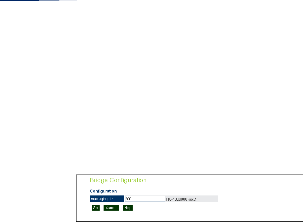
Bridge Configuration Use the Bridge Configuration page to configure the aging time for the MAC address
table.
The AP stores the MAC addresses for all known devices. All the addresses learned by
monitoring traffic are stored in a dynamic address table. This information is used to
pass traffic directly between inbound and outbound interfaces.
Figure 18: Bridge Configuration
The following items are displayed on the STP page:
◆mac aging time — The time after which a learned MAC address is discarded.
(Range: 10-1000000 seconds; Default: 300 seconds)

– 49 –
4Management Settings
This chapter describes management access settings on the access point. It includes
the following sections:
◆“Remote Management Settings” on page 49
◆“Access Limitation” on page 51
◆“Simple Network Management Protocol” on page 52
Remote Management Settings
The Web, Telnet, and SNMP management interfaces are enabled and open to all IP
addresses by default. To provide more security for management access to the
access point, specific interfaces can be disabled and management restricted to a
single IP address or a limited range of IP addresses.
Once you specify an IP address or range of addresses, access to management
interfaces is restricted to the specified addresses. If anyone tries to access a
management interface from an unauthorized address, the access point will reject
the connection.
Telnet is a remote management tool that can be used to configure the access point
from anywhere in the network. However, Telnet is not secure from hostile attacks.
The Secure Shell (SSH) can act as a secure replacement for Telnet. The SSH protocol
uses generated public keys to encrypt all data transfers passing between the access
point and SSH-enabled management station clients and ensures that data traveling
over the network arrives unaltered. Clients can then securely use the local user
name and password for access authentication.
Note that SSH client software needs to be installed on the management station to
access the access point for management via the SSH protocol.
Both HTTP and HTTPS service can be enabled independently. If you enable HTTPS,
you must indicate this in the URL: https://device:port_number]
When you start HTTPS, the connection is established in this way:
◆The client authenticates the server using the server’s digital certificate.
◆The client and server negotiate a set of security protocols to use for the
connection.
Chapter 4
| Management Settings
Remote Management Settings
– 50 –
◆The client and server generate session keys for encrypting and decrypting data.
◆The client and server establish a secure encrypted connection.
◆A padlock icon should appear in the status bar for Internet Explorer.
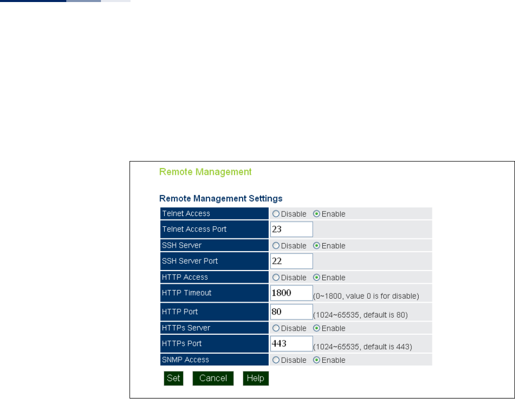
Figure 19: Remote Management
The following items are displayed on Admin Interface page:
◆Telnet Access — Enables/disables management access from Telnet interfaces.
(Default: enabled)
◆Telnet Access Port — Sets the specified Telnet port for communication.
(Default: 23)
◆SSH Server — Enables/disables management access from SSH Servers.
(Default: enabled)
◆SSH Server Port — Sets the specified SSH Server port for communication.
(Default: 22)
◆HTTP Access — Enables/disables management access from any IP address.
(Default: enabled)
◆HTTP Timeout — Specifies the time after which the HTTP connection will be
lost with a period of inactivity. (Default: 1800 seconds; Range: 1-1800 seconds;
0=disabled)
Chapter 4
| Management Settings
Access Limitation
– 51 –
◆HTTP Port — Specifies the HTTP port for IP connectivity. (Default: 80; Range
1024-65535)
◆HTTPS Server — Enables/disables management access from a HTTPS server.
(Default: enabled)
◆HTTPS Port — Specifies the HTTPS port for secure IP connectivity. (Default:
443; Range 1024-65535)
◆SNMP Access — Enables management access through SNMP. For more
information on SNMP access, see “Simple Network Management Protocol” on
page 52. (Default: enabled)
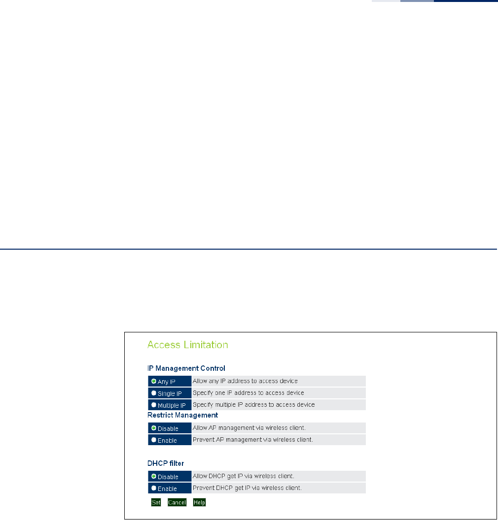
Access Limitation
The Access Limitation page limits management access to the access point from
specified IP addresses or wireless clients.
Figure 20: Access Limitation
The following items are displayed on the Access Limitation page:
IP Management Control
◆Any IP — Indicates that any IP address is allowed management access.
◆Single IP — Specifies a single IP address that is allowed management access.
◆Multiple IP — Specifies an address range as defined by the entered IP address
and subnet mask. For example, IP address 192.168.1.6 and subnet mask
255.255.255.0, defines all IP addresses from 192.168.1.1 to 192.168.1.254.

Chapter 4
| Management Settings
Simple Network Management Protocol
– 52 –
◆IP Address — Specifies the IP address.
◆Subnet Mask — Specifies the subnet mask in the form 255.255.255.x
Restrict Management
◆Enable/Disable — Enables/disables management of the device by a wireless
client. (Default: disabled)
DHCP Filter
◆Enable/Disable — Enables/disables the AP and wireless clients from obtaining
an IP address from a DHCP server installed on wireless client. (Default: disabled)
Simple Network Management Protocol
Simple Network Management Protocol (SNMP) is a communication protocol
designed specifically for managing devices on a network. Equipment commonly
managed with SNMP includes switches, routers and host computers. SNMP is
typically used to configure these devices for proper operation in a network
environment, as well as to monitor them to evaluate performance or detect
potential problems.
Managed devices supporting SNMP contain software, which runs locally on the
device and is referred to as an agent. A defined set of variables, known as managed
objects, is maintained by the SNMP agent and used to manage the device. These
objects are defined in a Management Information Base (MIB) that provides a
standard presentation of the information controlled by the agent. SNMP defines
both the format of the MIB specifications and the protocol used to access this
information over the network.
The access point includes an onboard agent that supports SNMP versions 1, 2c, and
3 clients. This agent continuously monitors the status of the access point, as well as
the traffic passing to and from wireless clients. A network management station can
access this information using SNMP management software that is compliant with
MIB II. To implement SNMP management, the access point must first have an IP
address and subnet mask, configured either manually or dynamically. Access to the
onboard agent using SNMP v1 and v2c is controlled by community strings. To
communicate with the access point, the management station must first submit a
valid community string for authentication.
Access to the access point using SNMP v3 provides additional security features that
cover message integrity, authentication, and encryption; as well as controlling
notifications that are sent to specified user targets.
SNMP Basic Settings The access point SNMP agent must be enabled to function (for versions 1, 2c, and 3
clients). Management access using SNMP v1 and v2c also requires community
Chapter 4
| Management Settings
Simple Network Management Protocol
– 53 –
strings to be configured for authentication. Trap notifications can be enabled and
sent to up to four management stations.
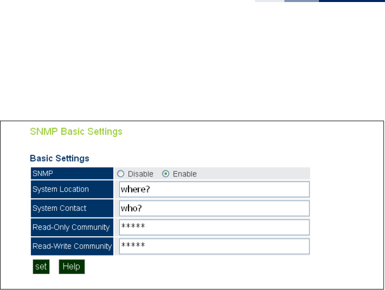
Figure 21: SNMP Basic Settings
The following items are displayed on this page:
◆SNMP — Enables or disables SNMP management access and also enables the
access point to send SNMP traps (notifications). (Default: Disable)
◆System Location — A text string that describes the system location.
(Maximum length: 255 characters)
◆System Contact — A text string that describes the system contact. (Maximum
length: 255 characters)
◆Read-Only Community — Defines the SNMP community access string that
has read-only access. Authorized management stations are only able to retrieve
MIB objects. (Maximum length: 23 characters, case sensitive; Default: public)
◆Read-Write Community — Defines the SNMP community access string that
has read/write access. Authorized management stations are able to both
retrieve and modify MIB objects. (Maximum length: 23 characters, case
sensitive; Default: private)
Chapter 4
| Management Settings
Simple Network Management Protocol
– 54 –
SNMP Trap Settings Traps indicating status changes are issued by the AP to specified trap managers.
You must specify trap managers so that key events are reported by the AP to your
management station (using network management platforms).
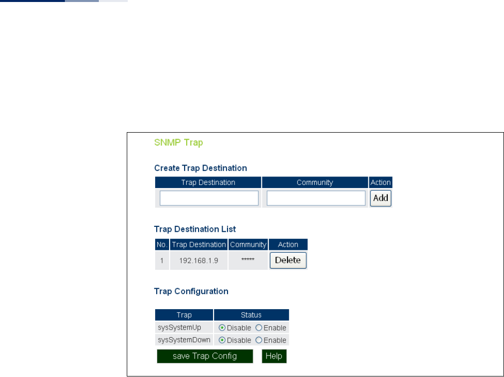
Figure 22: SNMP Trap Settings
The following items are displayed on this page:
◆Trap Destination — Specifies the recipient of SNMP notifications. Enter the IP
address or the host name. (Host Name: 1 to 63 characters, case sensitive)
◆Community — The community string sent with the notification operation.
(Maximum length: 23 characters, case sensitive; Default: public)
◆Action — Adds a new SNMP trap destination to the list.
◆Trap Destination List — Lists the configured SNMP trap destinations.
◆Trap Configuration — Enables or disables trap status.
■sysSystemUp: The access point is up and running.
■sysSystemDown: The access point is about to shutdown and reboot.
◆Save Trap Config — Applies the new parameters and saves them to RAM
memory. Also prompts a screen to inform you when it has taken affect. Clicking
‘OK’ returns to the home page. Changes will not be saved upon a reboot unless
the running configuration file is saved.
Chapter 4
| Management Settings
Simple Network Management Protocol
– 55 –
View Access Control
Model
To configure SNMPv3 management access to the AP, follow these steps:
1. Specify read and write access views for the AP MIB tree.
2. Configure SNMP user groups with the required security model (that is, SNMP
v1, v2c, or v3) and security level (authentication and privacy).
3. Assign SNMP users to groups, along with their specific authentication and
privacy passwords.
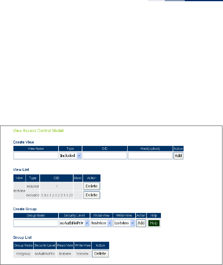
Figure 23: SNMP VACM
Creating Views
SNMPv3 views are used to restrict user access to specified portions of the MIB tree.
The are no predefined views by default.
The following items are displayed on the VACM page.
◆View Name – The name of the SNMP view. (Range: 1-32 characters)
◆Type – Indicates if the object identifier of a branch within the MIB tree is
included or excluded from the SNMP view.
◆OID – Allows you to configure the object identifiers of branches within the MIB
tree. Wild cards can be used to mask a specific portion of the OID string.
◆Mask (option) – A hexadecimal value with each bit masking the corresponding
ID in the MIB subtree. A “1” in the mask indicates an exact match and a “0”
indicates a “wild card.” For example, a mask value of 0xFFBF provides a bit mask

Chapter 4
| Management Settings
Simple Network Management Protocol
– 56 –
“1111 1111 1011 1111.” If applied to the subtree “1.3.6.1.2.1.2.2.1.1.23,” the zero
corresponds to the 10th subtree ID. When there are more subtree IDs than bits
in the mask, the mask is padded with ones.
◆View List – Shows the currently configured object identifiers of branches
within the MIB tree that define the SNMP view.
Creating Groups
An SNMPv3 group sets the access policy for its assigned users, restricting them to
specific read, write, and notify views. You can create new groups to map a set of
SNMP users to SNMP views.
◆Group Name – The name of the SNMP group. (Range: 1-32 characters)
◆Security Level – The security level used for the group:
■noAuthNoPriv – There is no authentication or encryption used in SNMP
communications.
■AuthNoPriv – SNMP communications use authentication, but the data is
not encrypted.
■AuthPriv – SNMP communications use both authentication and
encryption.
◆Read View – The configured view for read access. (Range: 1-32 characters)
◆Write View – The configured view for write access. (Range: 1-32 characters)
SNMPv3 Users The access point allows multiple SNMP v3 users to be configured. Each SNMPv3
user is defined by a unique name. Users must be configured with a specific security
level and assigned to a group. The SNMPv3 group restricts users to a specific read,
write, or notify view.
Figure 24: Configuring SNMPv3 Users

Chapter 4
| Management Settings
Simple Network Management Protocol
– 57 –
The following items are displayed on this page:
◆User Name — The SNMPv3 user name. (32 characters maximum)
◆Group — The SNMPv3 group name.
◆Auth Type — The authentication type used for the SNMP user; either MD5 or
none. When MD5 is selected, enter a password in the corresponding
Passphrase field.
◆Auth Passphrase — The authentication password or key associated with the
authentication and privacy settings. A minimum of eight plain text characters is
required.
◆Priv Type — The data encryption type used for the SNMP user; either DES or
none. When DES is selected, enter a key in the corresponding Passphrase field.
◆Priv Passphrase — The password or key associated with the authentication
and privacy settings. A minimum of eight plain text characters is required.
◆Action — Click the Add button to add a new user to the list. Click the edit
button to change details of an existing user. Click the Del button to remove a
user from the list.
Note:
Users must be assigned to groups that have the same security levels. For
example, a user who has “Auth Type” and “Priv Type” configured to MD5 and DES
respectively (that it, uses both authentication and data encryption) must be
assigned to the RWPriv group. If this same user were instead assigned to the read-
only (RO) group, the user would not be able to access the database.
SNMPv3 Targets An SNMP v3 notification Target ID is specified by the SNMP v3 user, IP address, and
UDP port. A user-defined filter can also be assigned to specific targets to limit the
notifications received to specific MIB objects. (Note that the filter must first be
configured. See “SNMPv3 Notification Filters” on page 58.)
To configure a new notification receiver target, define the parameters and select a
filter, if required. Note that the SNMP v3 user name must first be defined (See
“SNMPv3 Users” on page 56.)
Chapter 4
| Management Settings
Simple Network Management Protocol
– 58 –
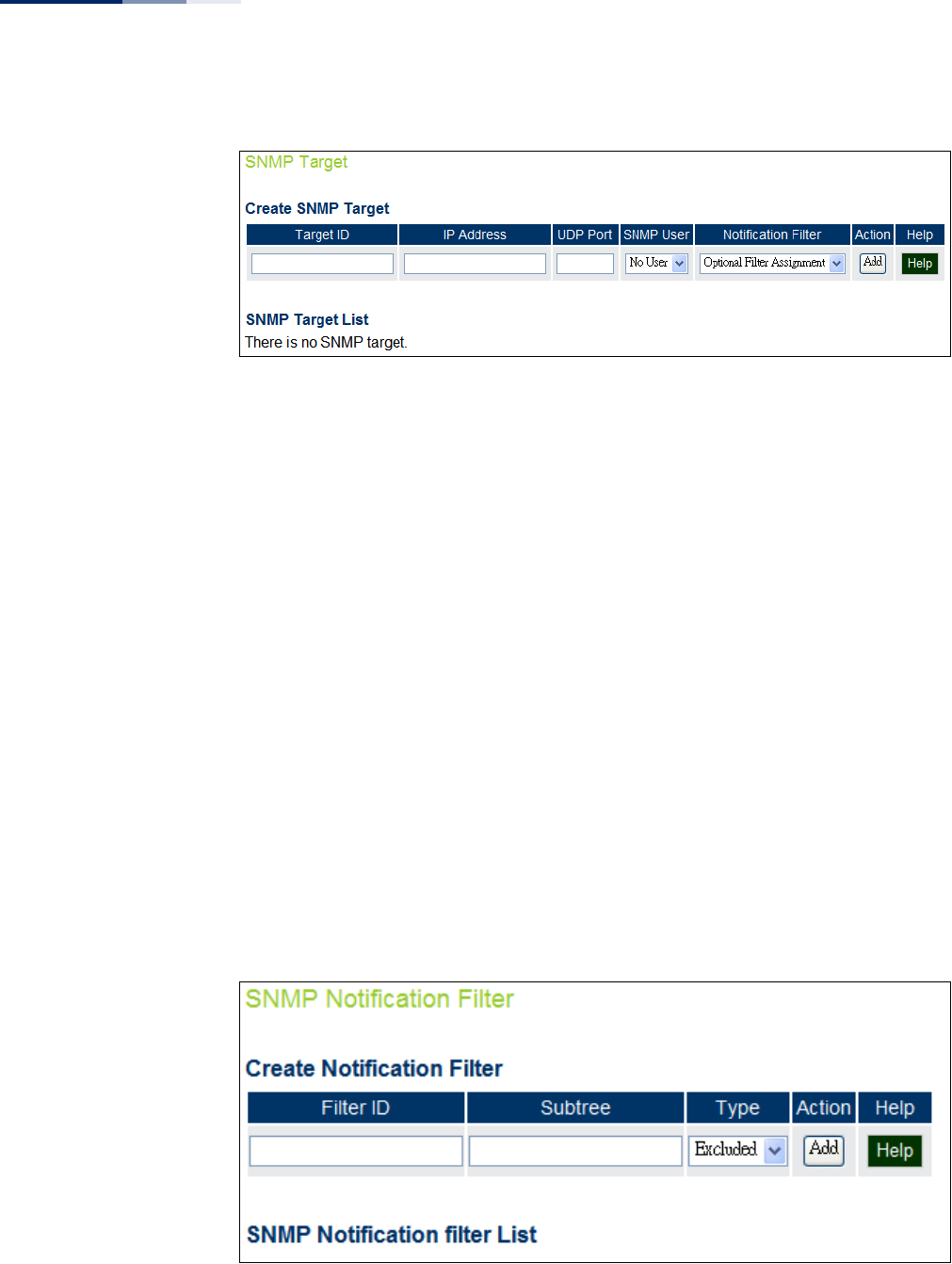
Figure 25: SNMPv3 Targets
The following items are displayed on this page:
◆Target ID — A user-defined name that identifies a receiver of notifications.
(Maximum length: 32 characters)
◆IP Address — Specifies the IP address of the receiving management station.
◆UDP Port — The UDP port that is used on the receiving management station
for notification messages.
◆SNMP User — The defined SNMP v3 user that is to receive notification
messages.
◆Notification Filter — The name of a user-defined notification filter that is
applied to the target.
SNMPv3 Notification
Filters
SNMP v3 users can be configured to receive notification messages from the access
point. An SNMP Target ID is created that specifies the SNMP v3 user, IP address, and
UDP port. A user-defined notification filter can be created so that specific
notifications can be prevented from being sent to particular targets.
Figure 26: SNMP Notification Filter

Chapter 4
| Management Settings
Simple Network Management Protocol
– 59 –
The following items are displayed on this page:
◆Filter ID — A user-defined name that identifies the filter. (Maximum length: 32
characters)
◆Subtree — Specifies MIB subtree to be filtered. The MIB subtree must be
defined in the form “.1.3.6.1” and always start with a “.”.
◆Type — Indicates if the filter is to “include” or “exclude” the MIB subtree objects
from the filter. Note that MIB objects included in the filter are not sent to the
receiving target and objects excluded are sent. By default all traps are sent, so
you can first use an “include” filter entry for all trap objects. Then use “exclude”
entries for the required trap objects to send to the target. Note that the filter
entries are applied in the sequence that they are defined.
◆Action — Adds the notification filter.
– 60 –
5Advanced Settings
This chapter describes advanced settings on the access point. It includes the
following sections:
◆“Local Bridge Filter” on page 60
◆“Link Layer Discovery Protocol” on page 61
◆“Access Control Lists” on page 63
◆“Link Integrity” on page 66
Local Bridge Filter
The access point can employ network traffic frame filtering to control access to
network resources and increase security. You can prevent communications
between wireless clients and prevent access point management from wireless
clients. Also, you can block specific Ethernet traffic from being forwarded by the
access point.
The Local Bridge Filter sets the global mode for wireless-to-wireless
communications between clients associated to Virtual AP (VAP) interfaces on the
access point. (Default: Disabled)
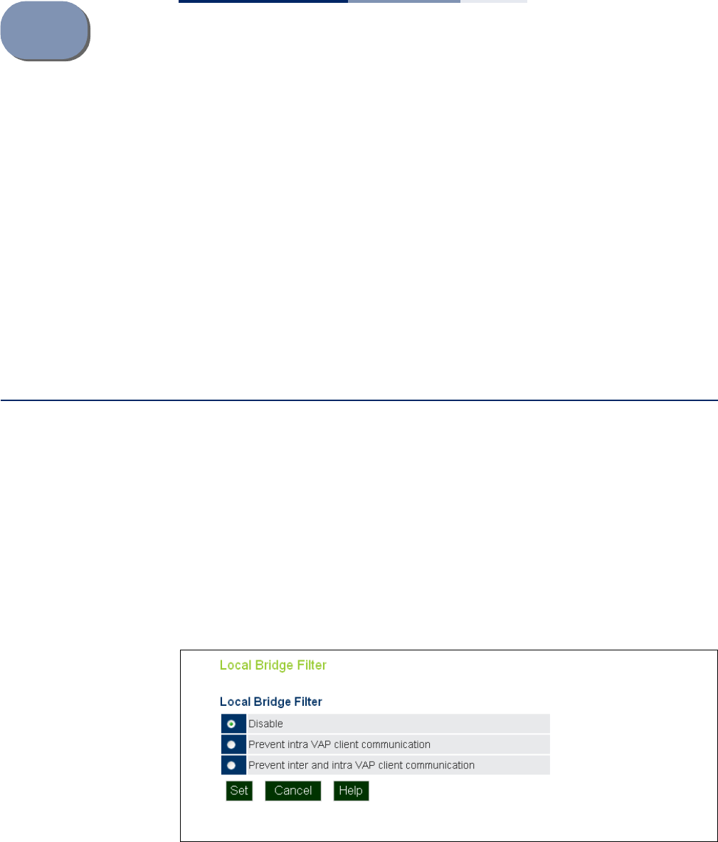
Figure 27: Local Bridge Filter
The following items are displayed on this page:
◆Disabled — All clients can communicate with each other through the access
point.
Chapter 5
| Advanced Settings
Link Layer Discovery Protocol
– 61 –
◆Prevent Intra VAP client communication — When enabled, clients associated
with a specific VAP interface cannot establish wireless communications with
each other. Clients can communicate with clients associated to other VAP
interfaces.
◆Prevent Inter and Intra VAP client communication — When enabled, clients
cannot establish wireless communications with any other client, either those
associated to the same VAP interface or any other VAP interface.
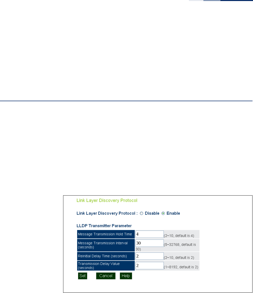
Link Layer Discovery Protocol
This page allows you to configure the Link Layer Discovery Protocol (LLDP). LLDP
allows devices in the local broadcast domain to share information about
themselves. LLDP-capable devices periodically transmit information in messages
called Type Length Value (TLV) fields to neighbor devices. Advertised information is
represented in Type Length Value (TLV) format according to the IEEE 802.1ab
standard, and can include details such as device identification, capabilities and
configuration settings.
This information can be used by SNMP applications to simplify troubleshooting,
enhance network management, and maintain an accurate network topology.
Figure 28: LLDP Settings
The following items are displayed on this page:
◆Disable/Enable — Disables/Enables LLDP on the access point.
◆Message Transmission Hold Time — Configures the time-to-live (TTL) value
sent in LLDP advertisements as shown in the formula below. (Range: 2-10;
Default: 4)

Chapter 5
| Advanced Settings
Link Layer Discovery Protocol
– 62 –
The time-to-live tells the receiving LLDP agent how long to retain all
information pertaining to the sending LLDP agent if it does not transmit
updates in a timely manner. TTL in seconds is based on the following rule:
(Transmission Interval * Hold time) ≤ 65536. Therefore, the default TTL is 4*30 =
120 seconds.
◆Message Transmission Interval (seconds) — Configures the periodic transmit
interval for LLDP advertisements. (Range: 5-32768 seconds; Default: 30
seconds)
This attribute must comply with the following rule: (Transmission Interval *
Hold Time) ≤ 65536, and Transmission Interval >= (4 * Delay Interval)
◆ReInitial Delay Time (seconds) — Configures the delay before attempting to
re-initialize after LLDP ports are disabled or the link goes down. (Range: 1-10
seconds; Default: 2 seconds)
When LLDP is re-initialized on a port, all information in the remote systems
LLDP MIB associated with this port is deleted.
◆Transmission Delay Value (seconds) — Configures a delay between the
successive transmission of advertisements initiated by a change in local LLDP
MIB variables. (Range: 1-8192 seconds; Default: 4 seconds)
The transmit delay is used to prevent a series of successive LLDP transmissions
during a short period of rapid changes in local LLDP MIB objects, and to
increase the probability that multiple, rather than single changes, are reported
in each transmission.
This attribute must comply with the rule: (4 * Delay Interval) ≤ Transmission
Interval
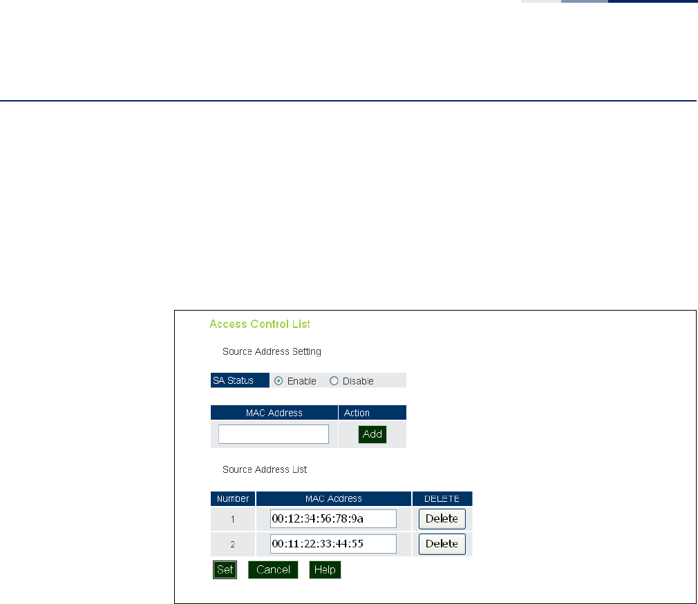
Chapter 5
| Advanced Settings
Access Control Lists
– 63 –
Access Control Lists
Access Control Lists allow you to configure a list of wireless client MAC addresses
that are not authorized to access the network. A database of MAC addresses can be
configured locally on the access point.
Source Address
Settings
The ACL Source Address Settings page enables traffic filtering based on the source
MAC address in the data frame.
Figure 29: Source ACLs
The following items are displayed on this page:
◆SA Status — Enables network traffic with specific source MAC addresses to be
filtered (dropped) from the access point.
◆MAC Address — Specifies a source MAC address to filter, in the form
xx.xx.xx.xx.xx.xx, or xx-xx-xx-xx-xx-xx.
◆Action — Selecting “Add” adds a new MAC address to the filter list, selecting
delete removes the specified MAC address.
◆Number — Specifies the number associated with the MAC address.
◆MAC Address — Displays the configured source MAC address.
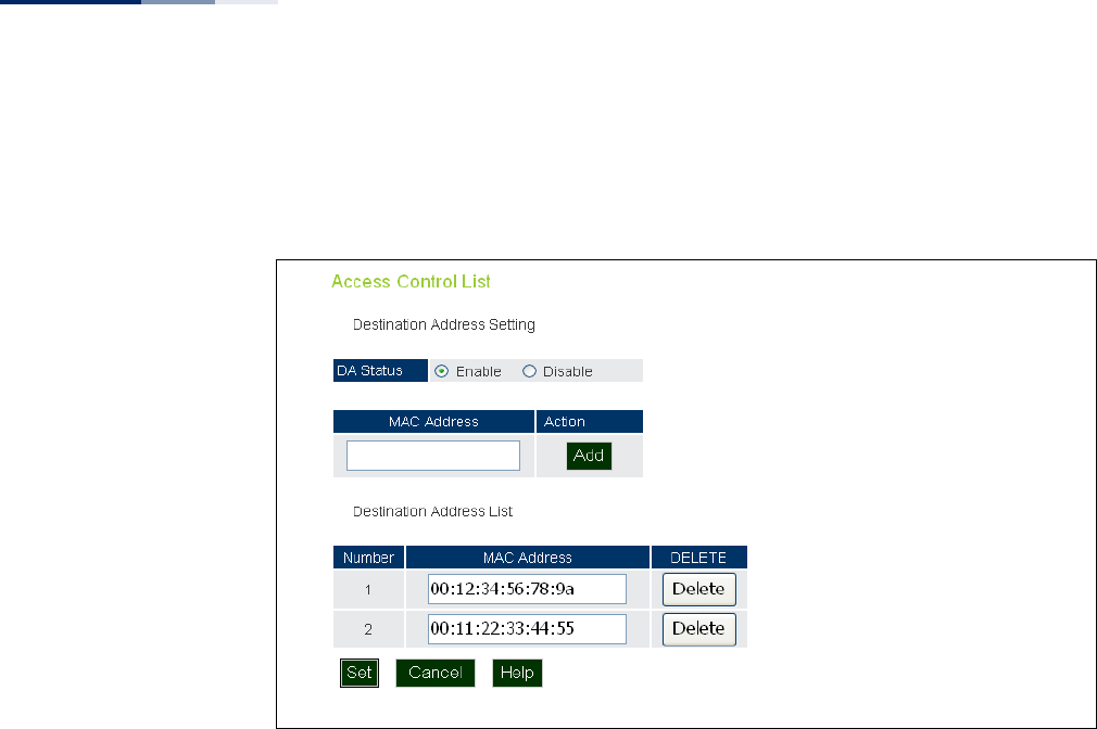
Chapter 5
| Advanced Settings
Access Control Lists
– 64 –
Destination Address
Settings
The ACL Destination Address Settings page enables traffic filtering based on the
destination MAC address in the data frame.
Figure 30: Destination ACLs
The following items are displayed on this page:
◆DA Status — Enables network traffic with specific destination MAC addresses
to be filtered (dropped) from the access point.
◆MAC Address — Specifies a destination MAC address to filter, in the form
xx:xx:xx:xx:xx:xx or xx-xx-xx-xx-xx-xx.
◆Action — Selecting “Add” adds a new MAC address to the filter list, selecting
delete deletes the specified MAC address.
◆Number — Specifies the number of the MAC address in the filter table.
◆MAC Address — Displays the configured destination MAC address.
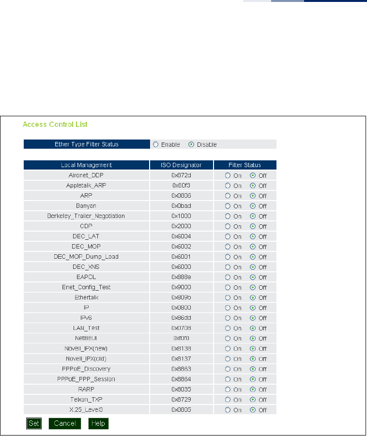
Chapter 5
| Advanced Settings
Access Control Lists
– 65 –
Ethernet Type The Ethernet Type Filter controls checks on the Ethernet type of all incoming and
outgoing Ethernet packets against the protocol filtering table. (Default: Disabled)
Figure 31: Ethernet Type Filter
The following items are displayed on this page:
◆Disabled — Access point does not filter Ethernet protocol types.
◆Enabled — Access point filters Ethernet protocol types based on the
configuration of protocol types in the filter table. If the status of a protocol is set
to “ON,” the protocol is filtered from the access point.
◆Local Management — Describes the Ethernet filter type.
◆ISO Designator — Describes the ISO Designator identifier.
◆Filter Status — Turns the filter on or off.
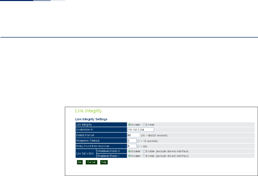
Chapter 5
| Advanced Settings
Link Integrity
– 66 –
Link Integrity
The AP provides a link integrity feature that can be used to ensure that wireless
clients are connected to resources on the wired network. The AP does this by
periodically sending Ping messages to a host device in the wired Ethernet network.
If the AP detects that the connection to the host has failed, it can disable the radio
interfaces, forcing clients to find and associate with another AP. When the
connection to the host is restored, the AP re-enables the radio interfaces.
Figure 32: Link Integrity
The following items are displayed on this page:
◆Link Integrity — Enables the feature. (Default: Disabled)
◆Destination IP — The link host IP address on the wired network to which Ping
messages are sent. (Default: 192.168.2.254)
◆Detect Interval — The interval time between each Ping sent to the host IP
address.(Range: 10-86400 seconds; Default: 60 seconds)
◆Response Timeout — The time to wait for a response to a Ping message.
(Range: 1-10 seconds; Default: 2 seconds)
◆Retry Count if no response — The number of consecutive failed Ping counts
before the link is determined as lost. (Range: 1-99; Default: 5)
◆Link Fail Action — When a link integrity test fails you can optionally disable
either radio interface. Note that the shutdown action does not apply for a VAP
interface set to WDS station mode. (Default: Disabled)

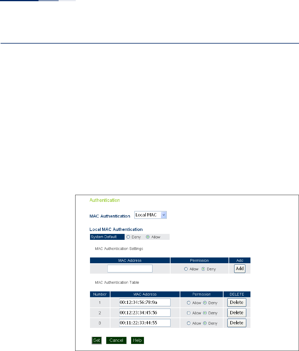
Chapter 6
| Wireless Settings
Authentication
– 68 –
Authentication
Wireless clients can be authenticated for network access by checking their MAC
address against the local database configured on the access point, or by using a
database configured on a central RADIUS server. Alternatively, authentication can
be implemented using the IEEE 802.1X network access control protocol.
You can configure a list of the MAC addresses for wireless clients that are authorized
to access the network. This provides a basic level of authentication for wireless
clients attempting to gain access to the network. A database of authorized MAC
addresses can be stored locally on the access point or remotely on a central RADIUS
server. (Default: Local MAC)
Local MAC
Authentication
Configures the local MAC authentication database. The MAC database provides a
mechanism to take certain actions based on a wireless client’s MAC address. The
MAC list can be configured to allow or deny network access to specific clients.
Figure 33: Local Authentication
The following items are displayed on Authentication page:
MAC Authentication — Selects between, disabled, Local MAC authentication and
RADIUS authentication.
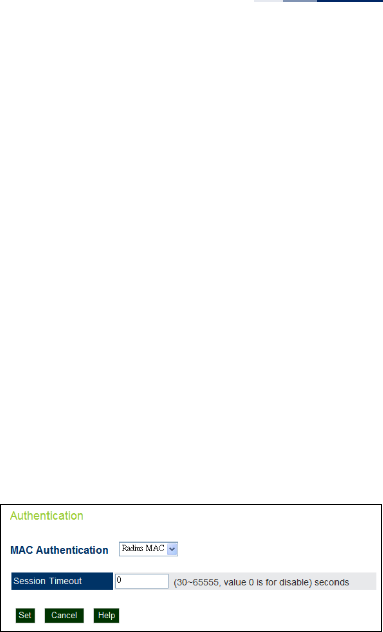
Chapter 6
| Wireless Settings
Authentication
– 69 –
◆Local MAC — The MAC address of the associating station is compared against
the local database stored on the access point. The Local MAC Authentication
section enables the local database to be set up.
◆System Default — Specifies a default action for all unknown MAC addresses
(that is, those not listed in the local MAC database).
■Deny: Blocks access for all MAC addresses except those listed in the local
database as “Allow.”
■Allow: Permits access for all MAC addresses except those listed in the local
database as “Deny.”
◆MAC Authentication Settings — Enters specified MAC addresses and
permissions into the local MAC database.
■MAC Address: Physical address of a client. Enter six pairs of hexadecimal
digits separated by hyphens; for example, 00-90-D1-12-AB-89.
■Permission: Select Allow to permit access or Deny to block access.
■Add/Delete: Adds or deletes the specified MAC address and permission
setting into or from the local database.
◆MAC Authentication Table — Displays current entries in the local MAC
database.
RADIUS MAC
Authentication
The MAC address of the associating station is sent to a configured RADIUS server for
authentication. When using a RADIUS authentication server for MAC address
authentication, the server must first be configured on the RADIUS page.
Figure 34: RADIUS Authentication
The following items are displayed on Authentication page:
MAC Authentication — Selects between, disabled, Local MAC authentication and
RADIUS authentication.

Chapter 6
| Wireless Settings
Authentication
– 70 –
◆RADIUS MAC — The MAC address of the associating station is compared
against the RADIUS server database. The RADIUS MAC Authentication section
enables the RADIUS database to be set up.
◆Session Timeout — The time period after which a connected client must be
re-authenticated. During the re-authentication process of verifying the client’s
credentials on the RADIUS server, the client remains connected the network.
Only if re-authentication fails is network access blocked. (Default: 0 means
disabled; Range: 30-65535 seconds)
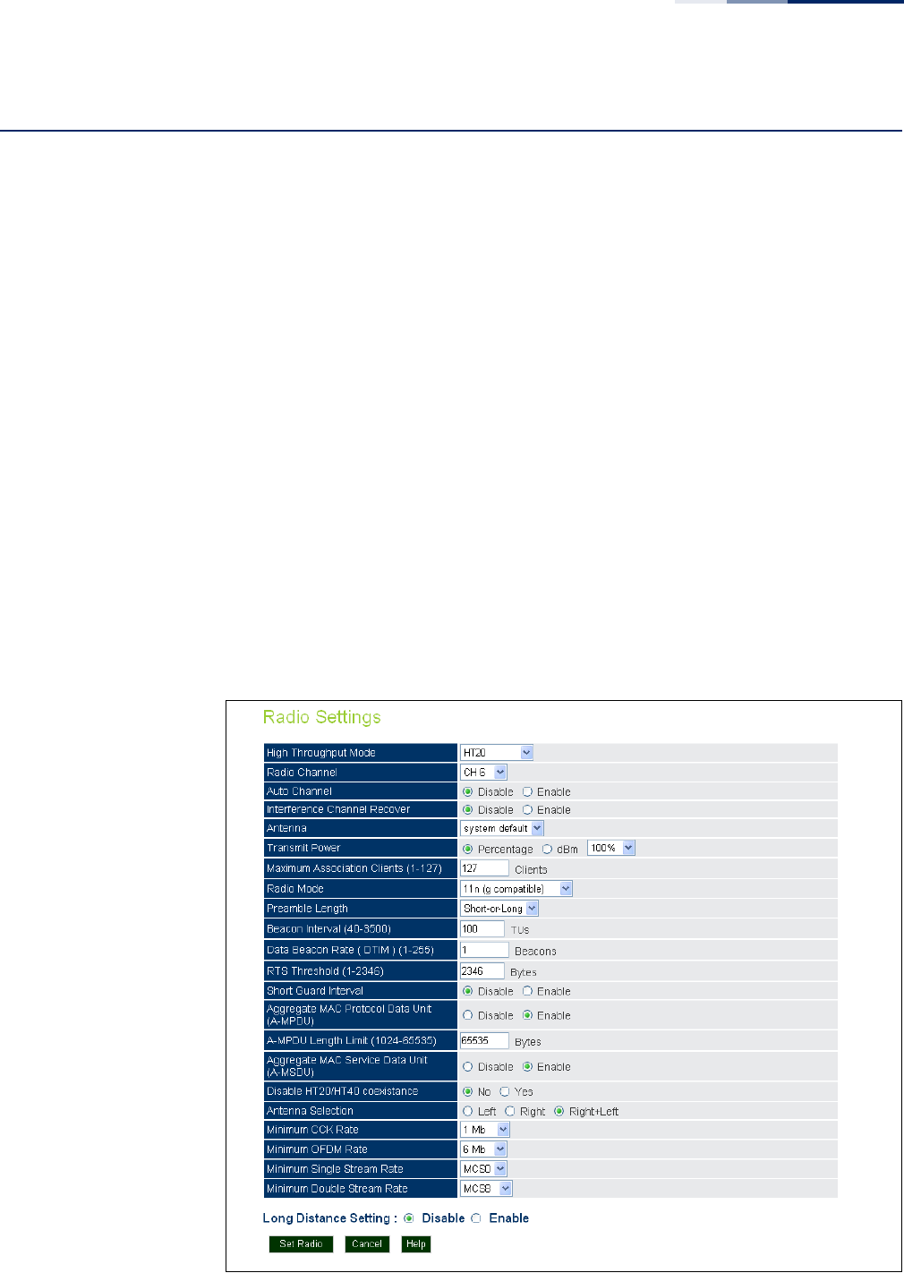
Chapter 6
| Wireless Settings
Radio Settings
– 71 –
Radio Settings
The IEEE 802.11n wireless interfaces include configuration options for radio signal
characteristics and wireless security features.
The AP can operate in several radio modes, mixed 802.11b/g/n (2.4 GHz), or mixed
802.11a/n (5 GHz). Note that the radios can operate at 2.4 GHz and 5 GHz at the
same time. The web interface identifies the radio configuration pages as:
◆Radio 0 — the 2.4 GHz 802.11b/g/n radio interface
◆Radio 1 — the 5 GHz 802.11a/n radio interface
Each radio supports 16 virtual access point (VAP) interfaces, referred to as VAP 0 ~
VAP 15. Each VAP functions as a separate access point, and can be configured with
its own Service Set Identification (SSID) and security settings. However, most radio
signal parameters apply to all VAP interfaces. The configuration options are nearly
identical, and are therefore both covered in this section of the manual. Traffic to
specific VAPs can be segregated based on user groups or application traffic. The
clients associate with each VAP in the same way as they would with separate
physical access points. The AP supports up to a total of 127 wireless clients across
all VAP interfaces per radio.
Figure 35: Radio Settings

Chapter 6
| Wireless Settings
Radio Settings
– 72 –
The following items are displayed on this page:
◆High Throughput Mode — The access point provides a channel bandwidth of
20 MHz by default giving an 802.11g connection speed of 54 Mbps and a
802.11n connection speed of up to 108 Mbps, and ensures backward
compliance for slower 802.11b devices. Setting the HT Channel Bandwidth to
40 MHz increases connection speed for 802.11n up to 300 Mbps. HT40plus
indicates that the secondary channel is above the primary channel. HT40minus
indicates that the secondary channel is below the primary channel.
(Default: HT20; Range:HT20, HT40PLUS, HT40MINUS)
◆Radio Channel — The radio channel that the access point uses to
communicate with wireless clients. When multiple access points are deployed
in the same area, set the channel on neighboring access points at least five
channels apart to avoid interference with each other. For example, for 11g/n
HT20 mode you can deploy up to three access points in the same area using
channels 1, 6, 11. Note that wireless clients automatically set the channel to the
same as that used by the access point to which it is linked. (The available
channels are dependent on the Radio Mode, High Throughput Mode, and
Country Code settings.)
◆Auto Channel — Selecting Auto Select enables the access point to
automatically select an unoccupied radio channel.
◆Interference Channel Recover — Rescans all channels when interference is
detected on the current channel, and then changes to a clear channel.
(Default: Disabled)
◆Antenna — Sets the antenna options for this AP to “system default.”
◆Transmit Power — Adjusts the power of the radio signals transmitted from the
access point. The higher the transmission power, the farther the transmission
range. Power selection is not just a trade off between coverage area and
maximum supported clients. You also have to ensure that high-power signals
do not interfere with the operation of other radio devices in the service area.
(Range - Percentage mode: min, 12.5%, 25%, 50%, 100%; Default: 100%)
(Range - dBm mode: 3-20 dBm; Default: 18 dBm)
◆Maximum Association Clients — The total maximum number of clients that
may associate with the radio. (Range: 1-127; Default: 127)
◆Radio Mode — Defines the radio operation mode.
■Radio 0 (2.4 GHz Radio) — Default: 11n (g compatible); Options: 11n (b&g
compatible), 11n (g compatible).
■Radio 1 (5 GHz Radio) — Default: 11n; Options: 11n (a compatible), 11n.

Chapter 6
| Wireless Settings
Radio Settings
– 73 –
Note:
Enabling the AP to communicate with 802.11b/g clients in both 802.11b/g/n
Mixed and 802.11n modes also requires that HT Operation be set to HT20.
◆Preamble Length — The radio preamble (sometimes called a header) is a
section of data at the head of a packet that contains information that the
wireless device and client devices need when sending and receiving packets.
You can set the radio preamble to long or short. A short preamble improves
throughput performance, whereas a long preamble is required when legacy
wireless devices are part of your network.
◆Beacon Interval — The rate at which beacon signals are transmitted from the
access point. The beacon signals allow wireless clients to maintain contact with
the access point. They may also carry power-management information. (Range:
40-3500 TUs; Default: 100 TUs)
◆Data Beacon Rate (DTIM) — The rate at which stations in sleep mode must
wake up to receive broadcast/multicast transmissions.
Known also as the Delivery Traffic Indication Map (DTIM) interval, it indicates
how often the MAC layer forwards broadcast/multicast traffic, which is
necessary to wake up stations that are using Power Save mode. The default
value of 2 indicates that the access point will save all broadcast/multicast
frames for the Basic Service Set (BSS) and forward them after every second
beacon. Using smaller DTIM intervals delivers broadcast/multicast frames in a
more timely manner, causing stations in Power Save mode to wake up more
often and drain power faster. Using higher DTIM values reduces the power used
by stations in Power Save mode, but delays the transmission of broadcast/
multicast frames. (Range: 1-255 beacons; Default: 1 beacon)
◆RTS Threshold — Sets the packet size threshold at which a Request to Send
(RTS) signal must be sent to a receiving station prior to the sending station
starting communications. The access point sends RTS frames to a receiving
station to negotiate the sending of a data frame. After receiving an RTS frame,
the station sends a CTS (clear to send) frame to notify the sending station that it
can start sending data.
If the RTS threshold is set to 1, the access point always sends RTS signals. If set
to 2346, the access point never sends RTS signals. If set to any other value, and
the packet size equals or exceeds the RTS threshold, the RTS/CTS (Request to
Send / Clear to Send) mechanism will be enabled.
The access points contending for the medium may not be aware of each other.
The RTS/CTS mechanism can solve this “Hidden Node Problem.” (Range: 1-2346
bytes: Default: 2346 bytes)
◆Short Guard Interval — The 802.11n draft specifies two guard intervals: 400ns
(short) and 800ns (long). Support of the 400ns GI is optional for transmit and
receive. The purpose of a guard interval is to introduce immunity to

Chapter 6
| Wireless Settings
Radio Settings
– 74 –
propagation delays, echoes, and reflections to which digital data is normally
very sensitive. Enabling the Short Guard Interval sets it to 400ns. (Default:
Disabled)
◆Aggregate MAC Protocol Data Unit (A-MPDU) — Enables / disables the
sending of this four frame packet header for statistical purposes. (Default:
Enabled)
◆A-MPDU Length Limit (1024-65535) — Defines the A-MPDU length. (Default:
65535 bytes; Range: 1024-65535 bytes)
◆Aggregate MAC Service Data Unit (A-MSDU) — Enables / disables the
sending of this four frame packet header for statistical purposes. (Default:
Enabled)
◆Disable HT20/HT40 Coexistance — Prevents 802.11n 20 MHz and 40 MHz
channel bandwidths from operating together in the same network.
(Default: Disabled)
◆Antenna Selection — Sets the radio to use one or both antennas. (Options:
Left, Right, Right+Left; Default: Right+Left)
◆Minimum CCK Rate — (2.4 GHz radio only) The minimum CCK data rate at
which the AP transmits packets on the wireless interface. (Options: 1, 2, 5.5,
11 Mbps; Default 1 Mbps)
◆Minimum OFDM Rate — The minimum OFDM data rate at which the AP
transmits packets on the wireless interface. (Range: 6, 9, 12, 18, 24, 36, 48,
54 Mbps; Default 6 Mbps)
◆Minimum Single Stream Rate — The minimum 802.11n single stream data
rate at which the AP transmits packets on the wireless interface. (Range: MCS0-
MCS7; Default MCS0)
◆Minimum Double Stream Rate — The minimum 802.11n double stream data
rate at which the AP transmits packets on the wireless interface. (Range: MCS8-
MCS15; Default MCS8)
◆Long Distance Setting — When you have long-distance links in the wireless
network, some timing parameters require an adjustment to maintain
communications.
Enter the approximate distance (in meters) of the client from the AP. Click on
the “Show Reference Data” button to compute a set of recommended values
for SlotTime, ACKTimeOut and CTSTimeOut. You can use the recommended
values or enter your own values that work for your specific environment.
◆Set Radio — Sets all entered parameters.
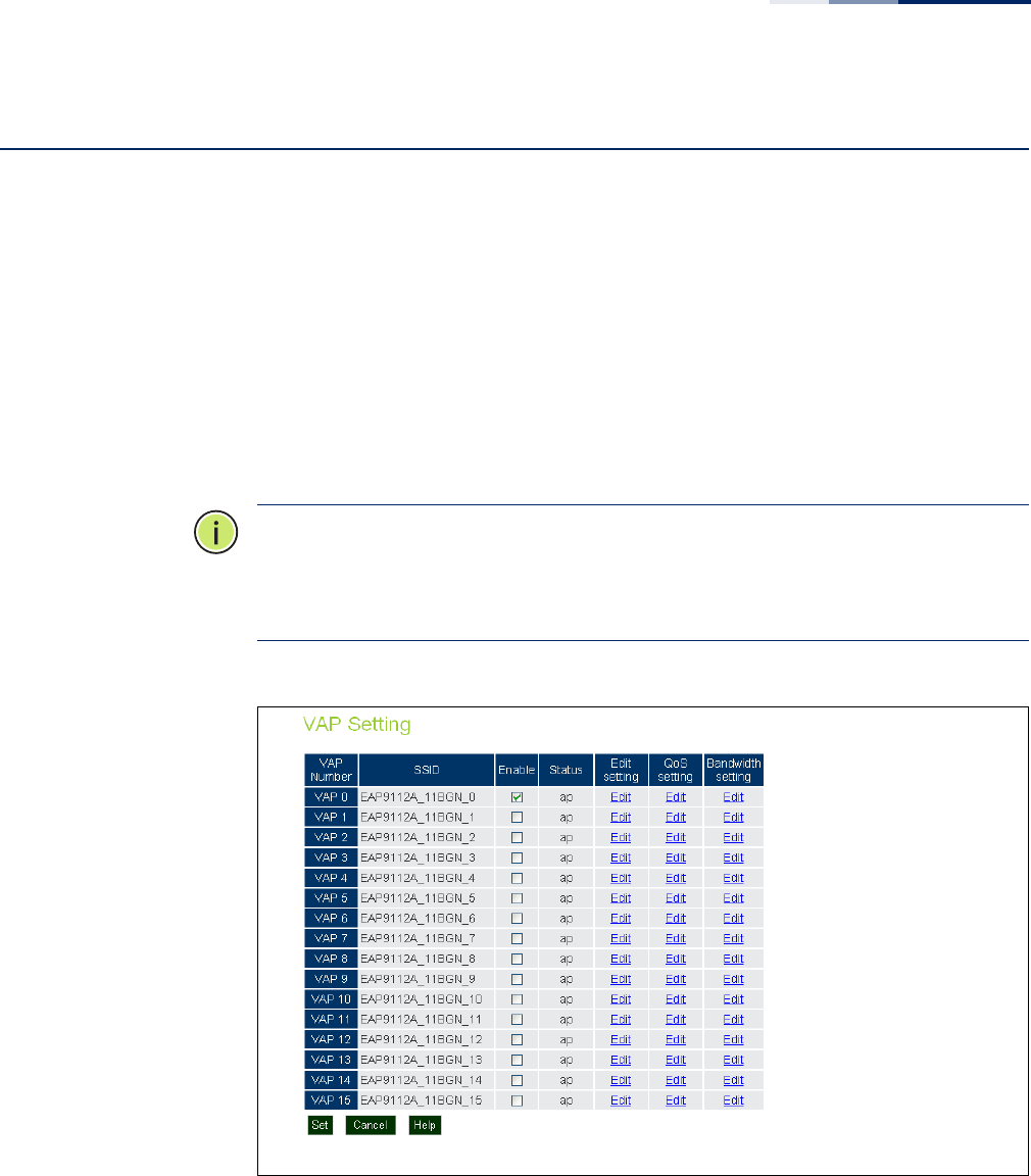
Chapter 6
| Wireless Settings
Virtual Access Points (VAPs)
– 75 –
Virtual Access Points (VAPs)
The AP supports up to 16 virtual access point (VAP) interfaces per radio, numbered
0 to 15. Each VAP functions as a separate access point, and can be configured with
its own Service Set Identification (SSID) and security settings. However, most radio
signal parameters apply to all VAP interfaces.
The VAPs function similar to a VLAN, with each VAP mapped to its own default
VLAN ID. Traffic to specific VAPs can be segregated based on user groups or
application traffic. All VAPs can support up to a total of 127 wireless clients,
whereby the clients associate with each VAP the same way as they would with
separate physical access points.
Note:
The radio channel settings for the access point are limited by local
regulations, which determine the number of channels that are available. See
“Operating Channels” on page 46 for additional information on the maximum
number channels available.
Figure 36: VAP Settings
The following items are displayed on this page:
◆VAP Number — The number associated with the VAP, 0-15.
◆SSID — The name of the basic service set provided by a VAP interface. Clients
that want to connect to the network through the access point must set their
SSID to the same as that of an access point VAP interface. (Default:
EAP9112A_11BGN_# (0 to 15); Range: 1-32 characters)
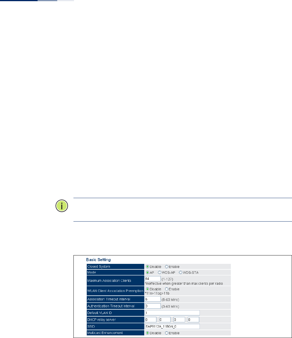
Chapter 6
| Wireless Settings
Virtual Access Points (VAPs)
– 76 –
◆Enable — Enables the specified VAP. (Default: Disabled)
◆Status — Displays the mode of the VAP. The default is set to "AP," for normal
access point services.
◆Edit Setting — Click to open the page to configure basic and security settings
for the selected VAP.
◆QoS Setting — Click to open the page to configure QoS settings for the
selected VAP.
◆Bandwidth Setting — Click to open the page to configure bandwidth control
for the selected VAP.
VAP Basic Settings Sets the basic operating mode and other settings for the VAP.
Each VAP can operate in one of three modes; normal AP mode, WDS-AP bridge AP
mode, or WDS-STA bridge station mode. The default mode is AP for the VAP to
support normal access point services.
Note:
For more information and examples for setting up WDS networks, see “WDS
Setup Examples” on page 45.
Note that the Basic Settings are the same for both AP and WDS-AP modes.
Figure 37: VAP Basic Settings
The following items are displayed on this page:
◆Closed System — When enabled, the VAP does not include its SSID in beacon
messages. Nor does it respond to probe requests from clients that do not
include a fixed SSID. (Default: Disable)

Chapter 6
| Wireless Settings
Virtual Access Points (VAPs)
– 77 –
◆Mode — Selects the mode in which the VAP will function.
■AP Mode: The VAP provides services to clients as a normal access point.
■WDS-AP Mode: The VAP operates as an access point in WDS mode, which
accepts connections from APs in WDS-STA mode.
■WDS-STA Mode: The VAP operates as a client station in WDS mode, which
connects to an access point VAP in WDS-AP mode. The user needs to
specify the MAC address of the access point in WDS-AP mode to which it
intends to connect.
◆Maximum Association Clients — The total maximum number of clients that
may associate with this VAP. The maximum is 127, which is the total associated
clients for all VAP interfaces. (Range: 1 to 127; Default 64)
◆WLAN Client Association Preemption — When enabled, the AP applies a
priority order for associating clients when the maximum clients for the VAP has
been reached. The priority order is 11n clients, 11a/g clients, then 11b clients.
When the association pool for the VAP is full and the AP receives an association
request from a high-priority (11n) client, the AP sends a disassociation to a
lower priority client (11a/g or 11b) in order to be able to associate the high-
priority client. If there are no lower-priority clients to disassociate, the AP will
reject the association request. (Default: Disabled)
◆Association Timeout Interval — The idle time interval (when no frames are
sent) after which a client is disassociated from the VAP interface. (Range: 5-60
minutes; Default: 30 minutes)
◆Authentication Timeout Interval — The time within which the client should
finish authentication before authentication times out.
(Range: 5-60 minutes; Default: 60 minutes)
◆Default VLAN ID — The VLAN ID assigned to wireless clients associated to the
VAP interface that are not assigned to a specific VLAN by RADIUS server
configuration. (Default: 1)
◆DHCP Relay Server — The IP address of the DHCP relay server. Dynamic Host
Configuration Protocol (DHCP) can dynamically allocate an IP address and
other configuration information to network clients that broadcast a request. To
receive the broadcast request, the DHCP server would normally have to be on
the same subnet as the client. However, when the access point’s DHCP relay
agent is enabled, received client requests can be forwarded directly by the
access point to a known DHCP server on another subnet. Responses from the
DHCP server are returned to the access point, which then broadcasts them
back to clients. (Default: 0.0.0.0 (disabled))
◆SSID — The service set identifier for the VAP.
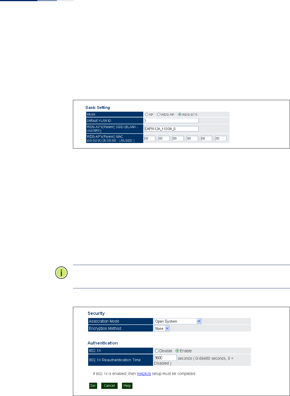
Chapter 6
| Wireless Settings
Virtual Access Points (VAPs)
– 78 –
◆Multicast Enhancement — When a wireless client joins a multicast group, this
feature converts multicast packets to unicast packets to improve multicast
video quality.
WDS-STA Mode Describes additional basic VAP settings when functioning in WDS-STA mode.
Figure 38: WDS-STA Mode
The following items are displayed in the VAP Basic Settings when WDS-AP mode is
selected:
◆WDS-AP (Parent) SSID — The SSID of the VAP on the connecting access point
that is set to WDS-AP mode.
◆WDS-AP (Parent) MAC — The MAC address of the VAP on the connecting
access point that is set to WDS-AP mode.
Wireless Security
Settings
Describes the wireless security settings for each VAP, including association mode,
encryption, and authentication.
Note:
For VAPs set to WDS-AP or WDS-STA mode, the security options are limited
to WPA-PSK and WPA2-PSK only.
Figure 39: Configuring VAPs - Security Settings

Chapter 6
| Wireless Settings
Virtual Access Points (VAPs)
– 79 –
The following items are available for VAP security:
◆Association Mode — Defines the mode with which the VAP will associate with
clients.
■Open System: The VAP is configured by default as an “open system,” which
broadcasts a beacon signal including the configured SSID. Wireless clients
with an SSID setting of “any” can read the SSID from the beacon and
automatically set their SSID to allow immediate connection.
■WPA: WPA employs a combination of several technologies to provide an
enhanced security solution for 802.11 wireless networks.
■WPA-PSK: For enterprise deployment, WPA requires a RADIUS
authentication server to be configured on the wired network. However, for
small office networks that may not have the resources to configure and
maintain a RADIUS server, WPA provides a simple operating mode that uses
just a pre-shared password for network access. The Pre-Shared Key mode
uses a common password for user authentication that is manually entered
on the access point and all wireless clients. The PSK mode uses the same
TKIP packet encryption and key management as WPA in the enterprise,
providing a robust and manageable alternative for small networks.
■WPA2: WPA was introduced as an interim solution for the vulnerability of
WEP pending the ratification of the IEEE 802.11i wireless security standard.
In effect, the WPA security features are a subset of the 802.11i standard.
WPA2 includes the now ratified 802.11i standard, but also offers backward
compatibility with WPA. Therefore, WPA2 includes the same 802.1X and PSK
modes of operation and support for TKIP encryption.
■WPA2-PSK: Clients using WPA2 with a Pre-shared Key are accepted for
authentication.
■WPA-WPA2 Mixed: Clients using WPA or WPA2 are accepted for
authentication.
■WPA-WPA2-PSK-mixed: Clients using WPA or WPA2 with a Pre-shared Key
are accepted for authentication.
◆Encryption Method — Selects an encryption method for the global key used
for multicast and broadcast traffic, which is supported by all wireless clients.
■WEP: WEP is used as the multicast encryption cipher. You should select
WEP only when both WPA and WEP clients are supported.
■TKIP: TKIP is used as the multicast encryption cipher.
■AES-CCMP: AES-CCMP is used as the multicast encryption cipher. AES-
CCMP is the standard encryption cipher required for WPA2.

Chapter 6
| Wireless Settings
Virtual Access Points (VAPs)
– 80 –
◆802.1X — The access point supports 802.1X authentication only for clients
initiating the 802.1X authentication process (i.e., the access point does not
initiate 802.1X authentication). For clients initiating 802.1X, only those
successfully authenticated are allowed to access the network. For those clients
not initiating 802.1X, access to the network is allowed after successful wireless
association with the access point. The 802.1X mode allows access for clients not
using WPA or WPA2 security.
◆Pre-Authentication — When using WPA2 over 802.1X, pre-authentication can
be enabled, which allows clients to roam to a new access point and be quickly
associated without performing full 802.1X authentication. (Default: Disabled)
◆802.1x Reauthentication Time — The time period after which a connected
client must be re-authenticated. During the re-authentication process of
verifying the client’s credentials on the RADIUS server, the client remains
connected the network. Only if re-authentication fails is network access
blocked. (Range: 0-65535 seconds; Default: 0 means disabled)
Wired Equivalent
Privacy (WEP)
WEP provides a basic level of security, preventing unauthorized access to the
network, and encrypting data transmitted between wireless clients and the VAP.
WEP uses static shared keys (fixed-length hexadecimal or alphanumeric strings)
that are manually distributed to all clients that want to use the network.
WEP is the security protocol initially specified in the IEEE 802.11 standard for
wireless communications. Unfortunately, WEP has been found to be seriously
flawed and cannot be recommended for a high level of network security. For more
robust wireless security, the access point provides Wi-Fi Protected Access (WPA)
and WPA2 for improved data encryption and user authentication.
Setting up shared keys enables the basic IEEE 802.11 Wired Equivalent Privacy
(WEP) on the access point to prevent unauthorized access to the network.
If you choose to use WEP shared keys instead of an open system, be sure to define
at least one static WEP key for user authentication and data encryption. Also, be
sure that the WEP shared keys are the same for each client in the wireless network.
All clients share the same keys, which are used for user authentication and data
encryption. Up to four keys can be specified.
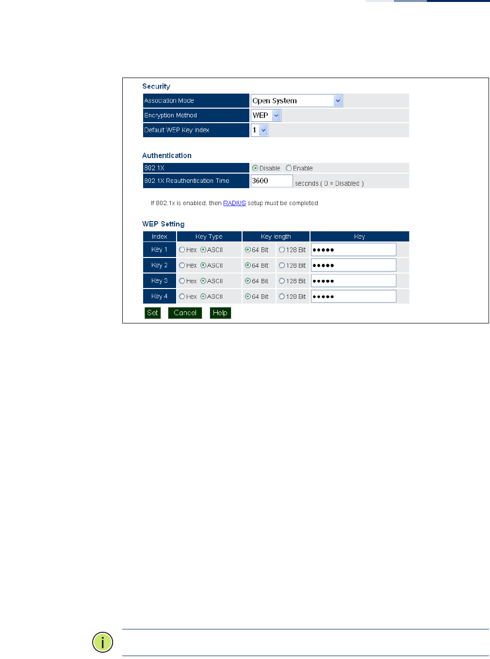
Chapter 6
| Wireless Settings
Virtual Access Points (VAPs)
– 81 –
Figure 40: WEP Configuration
The following items are on this page for WEP configuration:
◆Default WEP Key Index – Selects the key number to use for encryption for the
VAP interface. If the clients have all four WEP keys configured to the same
values, you can change the encryption key to any of the settings without
having to update the client keys.
(Default: Key 1)
◆Key Type – Select the preferred method of entering WEP encryption keys for
the VAP, either hexadecimal digits (Hex) or alphanumeric characters (ASCII).
◆Key Length – Select 64 Bit or 128 Bit key length. Note that the same size of
encryption key must be supported on all wireless clients. (Default: 64 bit)
◆Key – Enter up to four WEP encryption keys for the VAP.
■Hex: Enter keys as 10 hexadecimal digits (0-9 and A-F) for 64 bit keys, or 26
hexadecimal digits for 128 bit keys.
■ASCII: Enter keys as 5 alphanumeric characters for 64 bit keys, or 13
alphanumeric characters for 128 bit keys.
Note:
Key index, type, and length must match that configured on the clients.
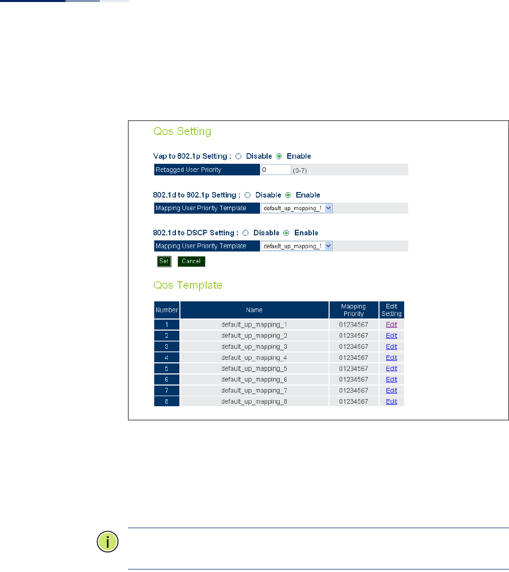
Chapter 6
| Wireless Settings
Virtual Access Points (VAPs)
– 82 –
VAP QoS Settings Click the QoS Setting link from the VAP Settings page to access the QoS priority
mapping configuration for traffic on the VAP interface.
Figure 41: QoS Settings
The following items are displayed in the VAP QoS Settings page:
◆VAP to 802.1p Setting — You can modify the VLAN priority tags of traffic on
the VAP interface with a specified priority value. Requires the default VLAN ID
for the VAP to be any other value than 1.
Note:
The VAP-to-802.1p priority QoS feature cannot be enabled together with the
802.1d-to-802.1p or 802.1d-to-DSCP features.
◆802.1d to 802.1p Setting — Enables the mapping of traffic priority from
WMM 802.1d priorities to 802.1p VLAN tag priority values. The priorities are
mapped according to the user-defined QoS Template map. Requires the
default VLAN ID for the VAP to be any other value than 1.
◆802.1d to DSCP Setting — Enables the mapping of traffic priority from WMM
802.1d priorities to IP DSCP priority values. The priorities are mapped according
to the user-defined QoS Template map.
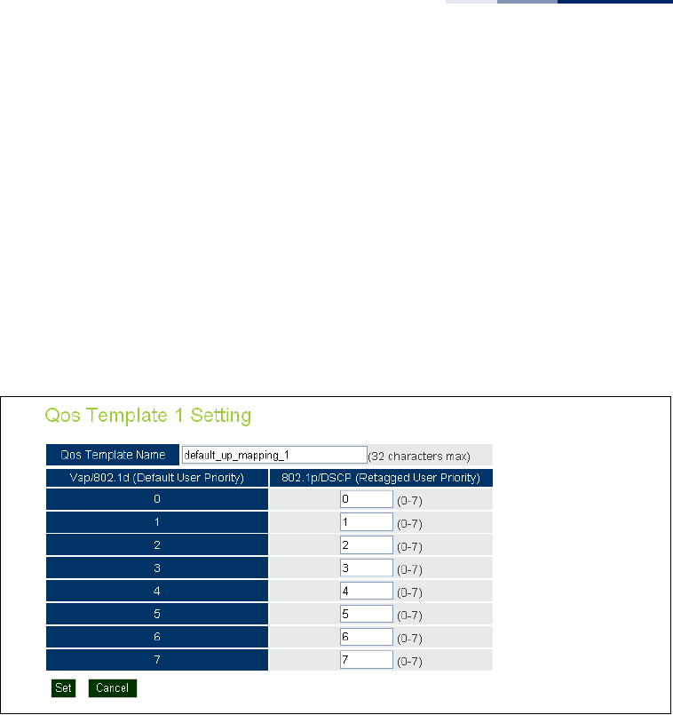
Chapter 6
| Wireless Settings
Virtual Access Points (VAPs)
– 83 –
Both “802.1d to 802.1p” mapping and “802.1d to DSCP” mapping can be
enabled simultaneously when the default VLAN ID for the VAP is any other
value than 1. When only “802.1d to DSCP” mapping is enabled, the default
VLAN ID for the VAP must be set to 1.
◆QoS Template — Enables up to eight user-defined priority mapping tables to
be configued. The tables are used to map the WMM 802.1d priorities to 802.1p/
DSCP priorities.
Click the “Edit” link in the list to define a template priority map.
Figure 42: QoS Template Setting
The following items are displayed in the QoS Template Setting page:
◆QoS Template Name — A descriptive name that identifies the mappng
template. All eight templates have a default name that can be edited by the
user (maximum 32 characters).
◆Vap/802.1d (Default User Priority) — The WMM 802.1d priority value in a
tagged packet.
◆802.1p/DSCP (Retagged User Priority) — The 802.1p or IP DSCP priority
value that replaces the WMM 802.1d value in tagged packets. (Range: 0-7)
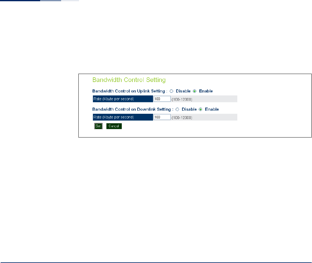
Chapter 6
| Wireless Settings
Rogue AP Detection
– 84 –
VAP Bandwidth
Settings
Click the Bandwidth Setting link from the VAP Settings page to configure rate
limiting for traffic on the VAP interface.
Figure 43: Bandwidth Settings
The following items are displayed on this page:
◆Bandwidth Control on Uplink Setting — Enables the rate limiting of traffic
from the VAP interface as it is passed to the wired network. You can set a
maximum rate in kbytes per second. (Range: 100-12000 Kbytes per second;
Default: 100 Kbytes per second)
◆Bandwidth Control on Downlink Setting — Enables the rate limiting of traffic
from the wired network as it is passed to the VAP interface. You can set a
maximum rate in kbytes per second. (Range: 100-12000 Kbytes per second;
Default: 100 Kbytes per second)
Rogue AP Detection
A “rogue AP” is either an access point that is not authorized to participate in the
wireless network, or an access point that does not have the correct security
configuration. Rogue APs can allow unauthorized access to the network, or fool
client stations into mistakenly associating with them and thereby blocking access
to network resources.
The access point can be configured to periodically scan all radio channels and find
other access points within range. A database of nearby access points is maintained
where any rogue APs can be identified. Rogue access points can be identified by
unknown BSSID (MAC address).
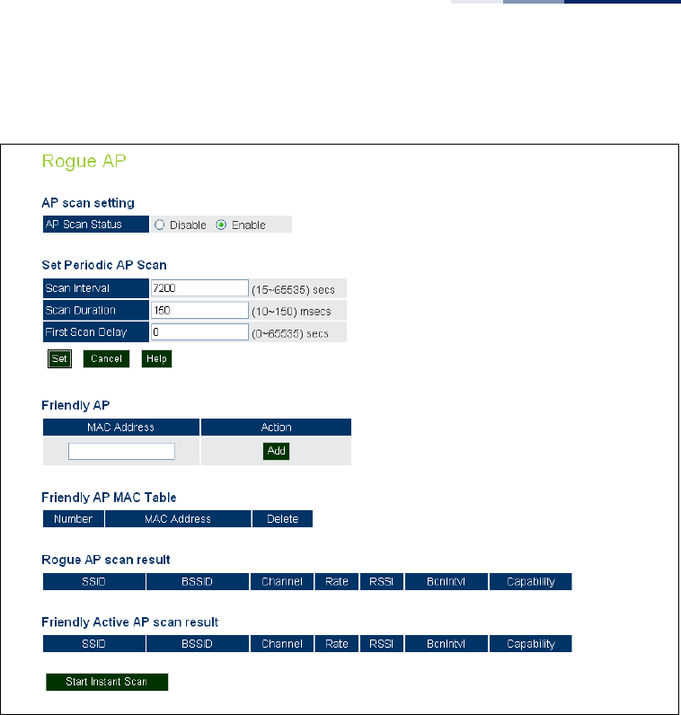
Chapter 6
| Wireless Settings
Rogue AP Detection
– 85 –
Figure 44: Rogue AP Detection
The following items are displayed on this page:
◆AP Scan Setting — Enables the periodic scanning for other nearby access
points. (Default: Disable)
◆Scan Interval — Sets the time between each rogue AP scan. (Range: 15 -65535
seconds; Default: 7200 seconds)
◆Scan Duration — Sets the length of time for each rogue AP scan. A long scan
duration time will detect more access points in the area, but causes more
disruption to client access. (Range: 10 -150 milliseconds; Default: 150
milliseconds)
◆First Scan Delay — Delays the start of rogue AP scanning after enabling the
feature or booting the AP. (Range: 0 -65535 seconds; Default: 65535 seconds)
◆Friendly AP — Allows you to enter the MAC address/Basic Service Set Identifier
(BSSID) of known APs in the network. These MAC addresses will be filtered out
of the list of detected APs during a scan.
◆Friendly AP MAC Table — Displays the MAC addresses of known APs in the
network.

Chapter 6
| Wireless Settings
Wi-Fi Multimedia (WMM)
– 86 –
◆Rogue AP Scan Result — Displays information of unknown APs detected
within the range of the AP running the scan.
◆Friendly Active AP Scan Result — Displays information of known APs
detected within the range of the AP running the scan.
◆Start Instant Scan — Starts an immediate rogue AP scan on the radio
interface. (Default: Disable)
Note:
While the access point scans a channel for rogue APs, wireless clients will not
be able to connect to the access point. Therefore, avoid frequent scanning or scans
of a long duration unless there is a reason to believe that more intensive scanning is
required to find a rogue AP.
Wi-Fi Multimedia (WMM)
Wireless networks offer an equal opportunity for all devices to transmit data from
any type of application. Although this is acceptable for most applications,
multimedia applications (with audio and video) are particularly sensitive to the
delay and throughput variations that result from this “equal opportunity” wireless
access method. For multimedia applications to run well over a wireless network, a
Quality of Service (QoS) mechanism is required to prioritize traffic types and
provide an “enhanced opportunity” wireless access method.
The access point implements QoS using the Wi-Fi Multimedia (WMM) standard.
Using WMM, the access point is able to prioritize traffic and optimize performance
when multiple applications compete for wireless network bandwidth at the same
time. WMM employs techniques that are a subset of the IEEE 802.11e QoS standard
and it enables the access point to interoperate with both WMM-enabled clients and
other devices that may lack any WMM functionality.
Access Categories — WMM defines four access categories (ACs): voice, video, best
effort, and background. These categories correspond to traffic priority levels and
are mapped to IEEE 802.1D priority tags (see “WMM Access Categories” on
page 87). The direct mapping of the four ACs to 802.1D priorities is specifically
intended to facilitate inter operability with other wired network QoS policies. While
the four ACs are specified for specific types of traffic, WMM allows the priority levels
to be configured to match any network-wide QoS policy. WMM also specifies a
protocol that access points can use to communicate the configured traffic priority
levels to QoS-enabled wireless clients.

Chapter 6
| Wireless Settings
Wi-Fi Multimedia (WMM)
– 87 –
WMM Operation — WMM uses traffic priority based on the four ACs; Voice, Video,
Best Effort, and Background. The higher the AC priority, the higher the probability
that data is transmitted.
When the access point forwards traffic, WMM adds data packets to four
independent transmit queues, one for each AC, depending on the 802.1D priority
tag of the packet. Data packets without a priority tag are always added to the Best
Effort AC queue. From the four queues, an internal “virtual” collision resolution
mechanism first selects data with the highest priority to be granted a transmit
opportunity. Then the same collision resolution mechanism is used externally to
determine which device has access to the wireless medium.
For each AC queue, the collision resolution mechanism is dependent on two timing
parameters:
◆AIFSN (Arbitration Inter-Frame Space Number), a number used to calculate the
minimum time between data frames
◆CW (Contention Window), a number used to calculate a random backoff time
After a collision detection, a backoff wait time is calculated. The total wait time is
the sum of a minimum wait time (Arbitration Inter-Frame Space, or AIFS)
determined from the AIFSN, and a random backoff time calculated from a value
selected from zero to the CW. The CW value varies within a configurable range. It
starts at CWMin and doubles after every collision up to a maximum value, CWMax.
After a successful transmission, the CW value is reset to its CWMin value.
Table 2: WMM Access Categories
Access
Category
WMM
Designation
Description 802.1D
Tags
AC_VO (AC3) Voice Highest priority, minimum delay. Time-sensitive
data such as VoIP (Voice over IP) calls. 7, 6
AC_VI (AC2) Video High priority, minimum delay. Time-sensitive data
such as streaming video. 5, 4
AC_BE (AC0) Best Effort Normal priority, medium delay and throughput.
Data only affected by long delays. Data from
applications or devices that lack QoS capabilities.
0, 3
AC_BK (AC1) Background Lowest priority. Data with no delay or throughput
requirements, such as bulk data transfers. 2, 1
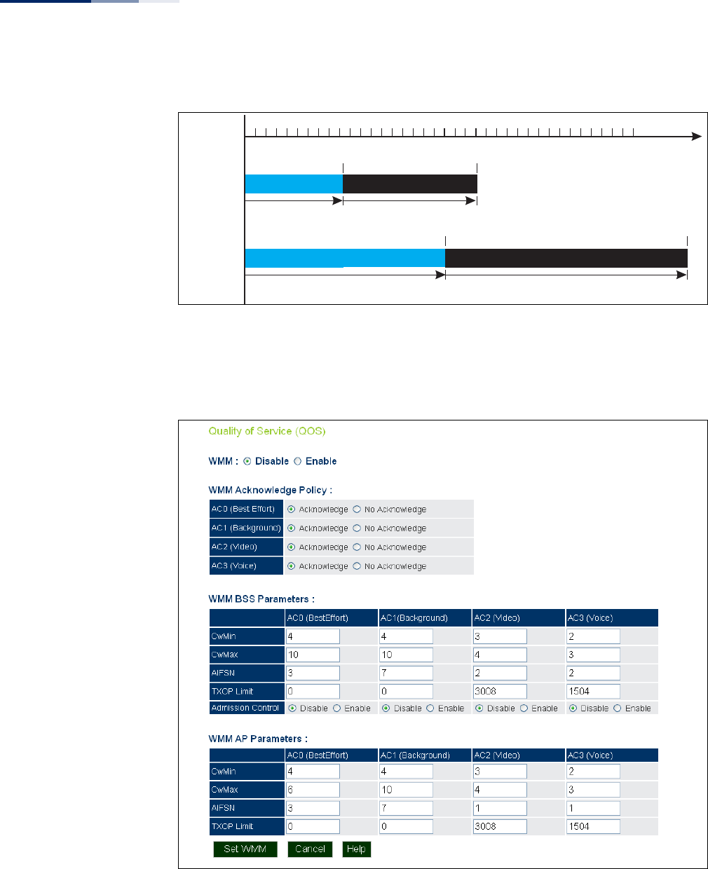
Chapter 6
| Wireless Settings
Wi-Fi Multimedia (WMM)
– 88 –
Figure 45: WMM Backoff Wait Times
For high-priority traffic, the AIFSN and CW values are smaller. The smaller values
equate to less backoff and wait time, and therefore more transmit opportunities.
Figure 46: QoS
AIFS Random Backoff
AIFS Random Backoff
CWMin CWMax
CWMin CWMax
Time
High Priority
Low Priority
Minimum Wait Time Random Wait Time
Minimum Wait Time Random Wait Time

Chapter 6
| Wireless Settings
Wi-Fi Multimedia (WMM)
– 89 –
The following items are displayed on this page:
◆WMM — Sets the WMM operational mode on the access point. When enabled,
the parameters for each AC queue will be employed on the access point and
QoS capabilities are advertised to WMM-enabled clients. (Default: Disabled)
■Disable: WMM is disabled.
■Enable: WMM must be supported on any device trying to associated with
the access point. Devices that do not support this feature will not be
allowed to associate with the access point.
◆WMM Acknowledge Policy — By default, all wireless data transmissions
require the sender to wait for an acknowledgement from the receiver. WMM
allows the acknowledgement wait time to be turned off for each Access
Category (AC) 0-3. Although this increases data throughput, it can also result in
a high number of errors when traffic levels are heavy. (Default: Acknowledge)
■Aknowledge — Applies the WMM policy.
■No Aknowledge — Ignores the WMM policy.
◆WMM BSS Parameters — These parameters apply to the wireless clients.
◆WMM AP Parameters — These parameters apply to the access point.
■logCWMin (Minimum Contention Window): The initial upper limit of the
random backoff wait time before wireless medium access can be
attempted. The initial wait time is a random value between zero and the
CWMin value. Specify the CWMin value in the range 0-15 microseconds.
Note that the CWMin value must be equal or less than the CWMax value.
■logCWMax (Maximum Contention Window): The maximum upper limit of
the random backoff wait time before wireless medium access can be
attempted. The contention window is doubled after each detected collision
up to the CWMax value. Specify the CWMax value in the range 0-15
microseconds. Note that the CWMax value must be greater or equal to the
CWMin value.
■AIFSN (Arbitration Inter-Frame Space): The minimum amount of wait time
before the next data transmission attempt. Specify the AIFS value in the
range 0-15 microseconds.
■TXOP Limit (Transmit Opportunity Limit): The maximum time an AC
transmit queue has access to the wireless medium. When an AC queue is
granted a transmit opportunity, it can transmit data for a time up to the
TxOpLimit. This data bursting greatly improves the efficiency for high data-
rate traffic. Specify a value in the range 0-65535 microseconds.

Chapter 6
| Wireless Settings
Wi-Fi Multimedia (WMM)
– 90 –
■Admission Control: The admission control mode for the access category.
When enabled, clients are blocked from using the access category. (Default:
Disabled)
◆Set WMM — Applies the new parameters and saves them to RAM memory.
Also prompts a screen to inform you when it has taken affect. Click “OK” to
return to the home page. Changes will not be saved upon a reboot unless the
running configuration file is saved.

– 91 –
7Maintenance Settings
Maintenance settings includes the following sections:
◆“Upgrading Firmware” on page 91
◆“Running Configuration” on page 93
◆“Resetting the Access Point” on page 94
◆“Scheduled Reboot” on page 95
Upgrading Firmware
You can upgrade new access point software from a local file on the management
workstation, or from an FTP or TFTP server. New software may be provided
periodically from your distributor.
After upgrading new software, you must reboot the access point to implement the
new code. Until a reboot occurs, the access point will continue to run the software
it was using before the upgrade started. Also note that new software that is
incompatible with the current configuration automatically restores the access
point to the factory default settings when first activated after a reboot.
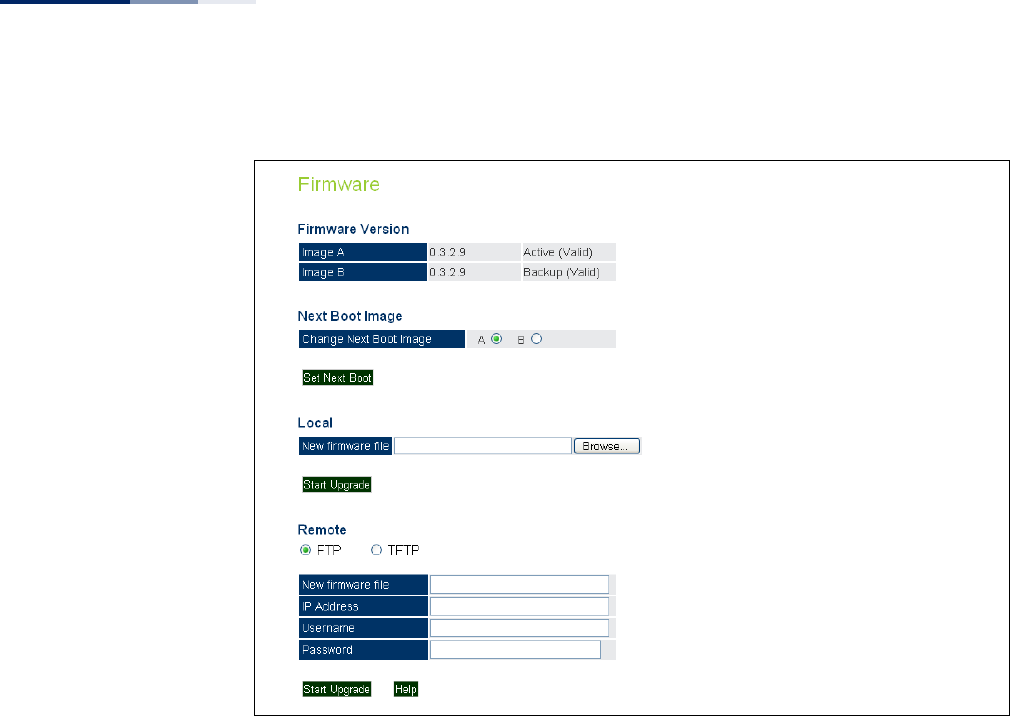
Chapter 7
| Maintenance Settings
Upgrading Firmware
– 92 –
Figure 47: Firmware
The following items are displayed on this page:
◆Firmware Version — Displays the software image version that is being used as
the runtime image. The “Active” image is the current running software, and the
“Backup” image is the second software file installed on the AP, but not running.
◆Next Boot Image — Specifies what version of software will be used as a
runtime image upon bootup.
◆Set Next Boot — Applies the runtime image setting.
◆Local — Downloads an operation code image file from the web management
station to the access point using HTTP. Use the Browse button to locate the
image file locally on the management station and click Start Upgrade to
proceed.
■New Firmware File: Specifies the name of the code file on the server. The
new firmware file name should not contain slashes (\ or /), the leading letter
of the file name should not be a period (.), and the maximum length for file
names is 32 characters for files on the access point. (Valid characters: A-Z, a-
z, 0-9, “.”, “-”, “_”)
◆Remote — Downloads an operation code image file from a specified remote
FTP or TFTP server. After filling in the following fields, click Start Upgrade to
proceed.
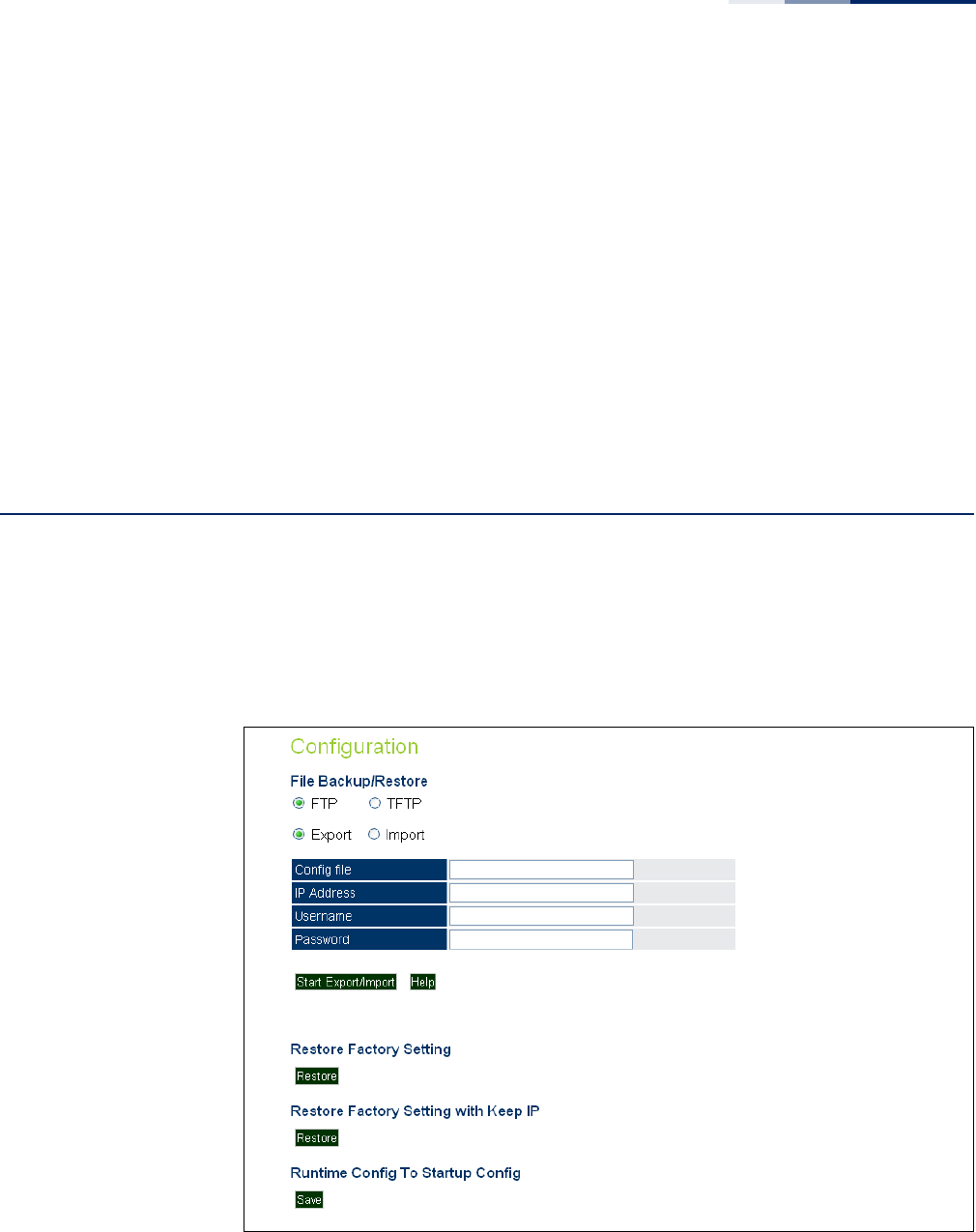
Chapter 7
| Maintenance Settings
Running Configuration
– 93 –
■New Firmware File: Specifies the name of the code file on the server. The
new firmware file name should not contain slashes (\ or /), the leading letter
of the file name should not be a period (.), and the maximum length for file
names on the FTP/TFTP server is 255 characters or 32 characters for files on
the access point. (Valid characters: A-Z, a-z, 0-9, “.”, “-”, “_”)
■IP Address: IP address or host name of FTP or TFTP server.
■Username: The user ID used for login on an FTP server.
■Password: The password used for login on an FTP server.
◆Start Upgrade — Commences the upgrade process.
Running Configuration
A copy of a previous running configuration may be uploaded to the access point as
a saved file from a remote location, or the current configuration saved and stored
for restoration purposes at a later point. A configuration file may be saved or
downloaded to/from a specified remote FTP or TFTP server.
Figure 48: Running Configuration File

Chapter 7
| Maintenance Settings
Resetting the Access Point
– 94 –
The following items are displayed on this page:
◆File Backup/Restore — Downloads an operation code image file from a
specified remote FTP or TFTP server. After filling in the following fields, click
Start Export/Import to proceed.
◆Export/Import — Select Export to upload a file to an FTP/TFTP server. Select
Import to download a file from an FTP/TFTP server.
◆Config file — Specifies the name of the configuration file. A path on the server
can be specified using “/” in the name, providing the path already exists; for
example, “myfolder/.” Other than to indicate a path, the file name must not
contain any slashes (\ or /), the leading letter cannot be a period (.), and the
maximum length for file names on the FTP/TFTP server is 255 characters. (Valid
characters: A-Z, a-z, 0-9, “.”, “-”, “_”)
◆IP Address — IP address or host name of FTP or TFTP server.
◆Username — The user ID used for login on an FTP server.
◆Password — The password used for login on an FTP server.
◆Start Import/Export — Initiates the selected backup or restore.
◆Restore Factory Setting — Click the Restore button to reset the configuration
settings for the access point to the factory defaults and reboot the system. Note
that all user configured information will be lost. You will have to re-enter the
default user name and password to re-gain management access to this device.
◆Restore Factory Setting with Keep IP — Click the Restore button to reset the
AP’s configuration settings, except for the IP, to the factory defaults and reboot
the system. Note that other than the IP settings, all user configured information
will be lost. You will have to re-enter the default user name and password to re-
gain management access to this device.
◆Running Config To Startup Config — Click “Save” to save the running
configuration to the startup file.
Resetting the Access Point
The Reset page allows you to reset the access point and save the running
configuration before the reboot.
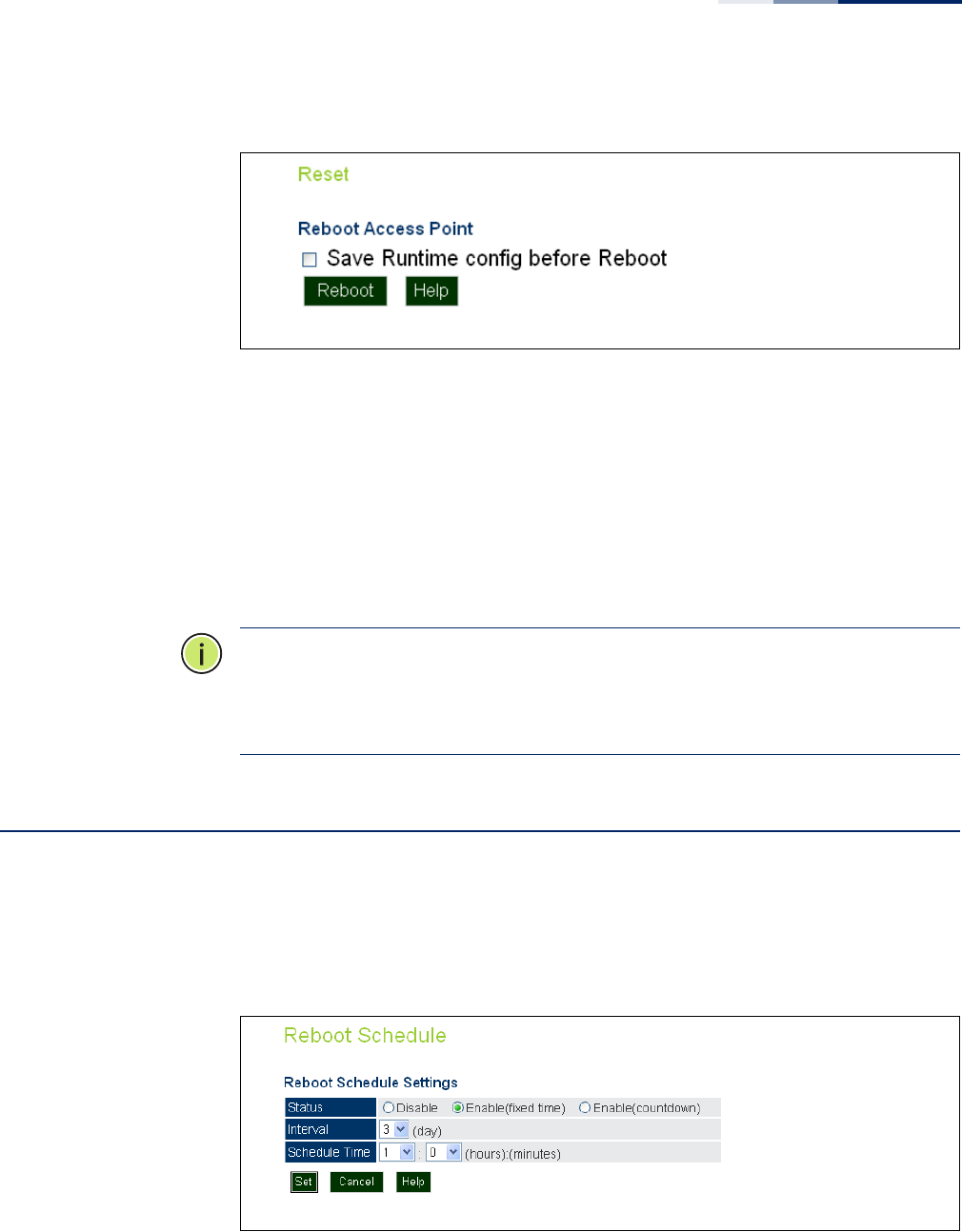
Chapter 7
| Maintenance Settings
Scheduled Reboot
– 95 –
Figure 49: Resetting the Access Point
The following items are displayed on this page:
◆Save Runtime config before Reboot — Checking this option saves the
current running configuration to the startup file.
◆Reboot — Click the “Reboot” button to reset the configuration settings for the
AP and reboot the system. Note that all unsaved user configured information
will be lost.
Note:
If you have upgraded system software, then you must reboot the access
point to implement the new operation code. New software that is incompatible
with the current configuration automatically restores the access point to default
values when first activated after a reboot.
Scheduled Reboot
The Reboot Schedule page allows you to set the AP to reboot on a specified time
schedule. The time can be either by days and hours, or a simple countdown in
minutes.
Figure 50: Reboot Schedule — Fixed Time
The following items are displayed on this page:
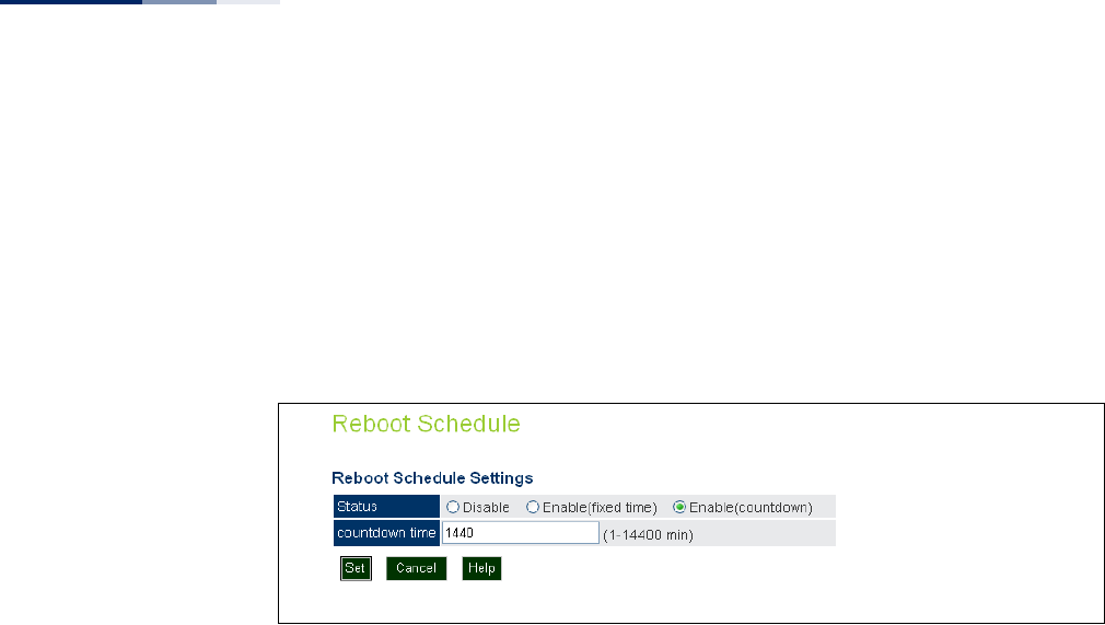
Chapter 7
| Maintenance Settings
Scheduled Reboot
– 96 –
◆Status — Selects a fixed time interval or a countdown time, or disables the
feature.
◆Interval — Specifies the interval in days. (Range: 1~7 days)
◆Schedule Time — Specifies a time in hours and minutes. (Range: 0~23 hours,
0~59 minutes)
Figure 51: Reboot Schedule — Countdown Time
The following items are displayed on this page:
◆Status — Selects a fixed time interval or a countdown time, or disables the
feature.
◆Countdown Time — Specifies a time in minutes. (Default: 14400 minutes;
Range: 1~14400 minutes)

– 97 –
8Status Information
The Information menu displays information on the current system configuration,
the wireless interface, the station status and system logs.
Status Information includes the following sections:
◆“AP Status” on page 98
◆“Station Status” on page 101
◆“Station Statistics” on page 102
◆“Event Logs” on page 103
◆“WDS Status” on page 104
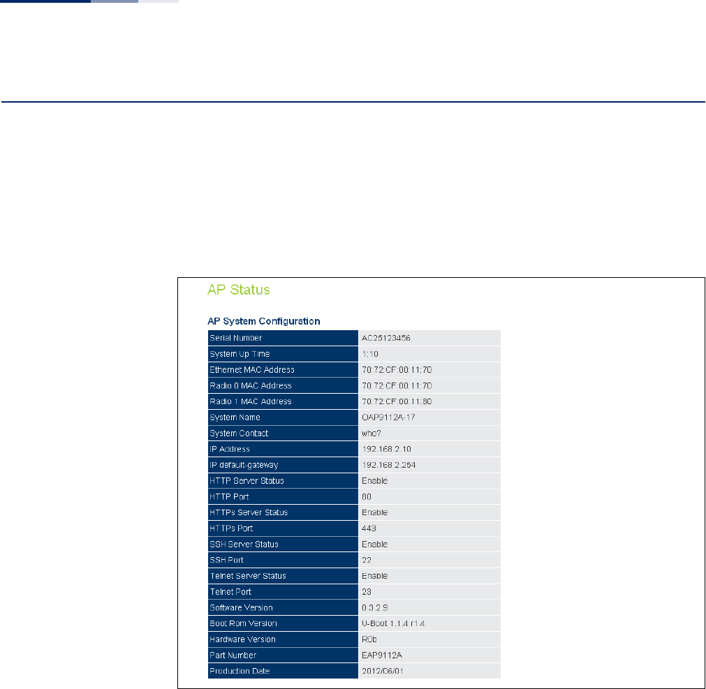
Chapter 8
| Status Information
AP Status
– 98 –
AP Status
The AP Status window displays basic system configuration settings, as well as the
settings for the wireless interfaces.
AP System
Configuration
The AP System Configuration table displays the basic system configuration settings
Figure 52: AP System Configuration
The following items are displayed on this page:
◆Serial Number — The serial number of the physical access point.
◆System Up Time — Length of time the management agent has been up.
◆Ethernet MAC Address — The physical layer address for the Ethernet port.
◆Radio 0 MAC Address — The base physical layer address of the 2.4 GHz
interface.
◆Radio 1 MAC Address — The base physical layer address for the 5 GHz
interface.

Chapter 8
| Status Information
AP Status
– 99 –
◆System Name — Name assigned to this system.
◆System Contact — Administrator responsible for the system.
◆IP Address — IP address of the management interface for this device.
◆IP Default Gateway — IP address of the gateway router between this device
and management stations that exist on other network segments.
◆HTTP Server Status — Shows if management access via HTTP is enabled.
◆HTTP Port — Shows the TCP port used by the HTTP interface.
◆HTTPS Server Status — Shows if management access via HTTPS is enabled.
◆HTTPS Port — Shows the TCP port used by the HTTPS interface.
◆SSH Server Status — Shows if management access via SSH is enabled.
◆SSH Port — Shows the TCP port used for SSH access.
◆Telnet Server Status — Shows if management access via Telnet is enabled.
◆Telnet Por t — Shows the TCP port used for Telnet access.
◆Software Version — Shows the software version number.
◆Boot Rom Version — Show the boot software version number.
◆Hardware Version — Shows the unit’s hardware version number.
◆Part Number — Shows the model number of the unit.
◆Production Date — Shows the production date of the unit.
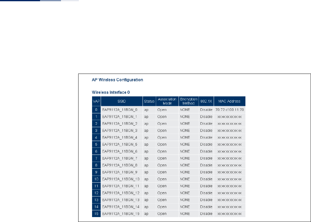
Chapter 8
| Status Information
AP Status
– 100 –
AP Wireless
Configuration
The AP Wireless Configuration displays the VAP interface settings for the 2.4 GHz
and 5 GHz radios.
Figure 53: AP Wireless Configuration
The following items are displayed on this page for the 2.4 GHz and 5 GHz radio
interfaces:
◆VAP — Displays the VAP number.
◆SSID — The service set identifier for the VAP interface.
◆Status — Displays the interface mode setting, either “ap”, “wds-ap”, or “wds-sta”.
◆Association Mode — Shows the basic security mode configured for the VAP.
◆Encryption Method — Displays the encryption method used on the interface.
◆802.1X — Shows if IEEE 802.1X access control for wireless clients is enabled.
◆MAC Address — Displays the MAC address of the VAP interface.
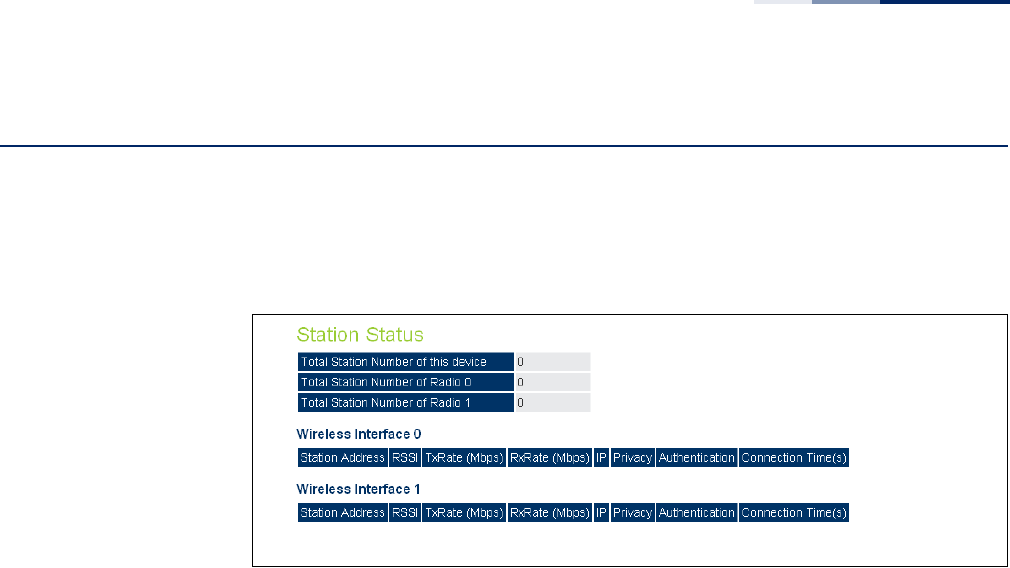
Chapter 8
| Status Information
Station Status
– 101 –
Station Status
The Station Status window shows the wireless clients currently associated with the
2.4 GHz and 5 GHz radio interfaces.
Figure 54: Station Status
The following items are displayed on this page:
◆Total Station Number of this device — The total number of clients associated
to the AP.
◆Total Station Number of Radio 0 — The total number of clients associated to
the 2.4 GHz radio.
◆Total Station Number of Radio 1 — The total number of clients associated to
the 5 GHz radio.
◆Station Address — The MAC address of the wireless client.
◆RSSI — The Receive Signal Strength Indicator for the wireless client.
◆TxRate (Mbps) — The data tranmit rate to the wireless client.
◆RxRate (Mbps) — The data receive rate from the wireless client.
◆IP — The IP address assigned to the wireless client.
◆Privacy — The data encryption method used by the wireless client.
◆Authentication — The authentication method used by the wireless client.
◆Connection Time — The time the wireless client has been associated.
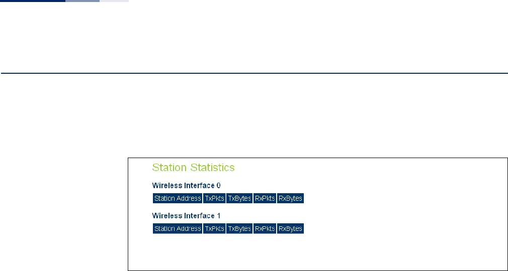
Chapter 8
| Status Information
Station Statistics
– 102 –
Station Statistics
The Station Statistics window shows the statistic information for wireless clients
currently associated with the 2.4 GHz and 5 GHz radio interfaces.
Figure 55: Station Statistics
The following items are displayed on this page:
◆Station Address — The MAC address of the wireless client.
◆TxPkts — The number of transmitted packets from this client.
◆TxBytes — The number of transmitted bytes from this client.
◆RxPkts — The number of received packets from this client.
◆RxBytes — The number of received bytes from this client.
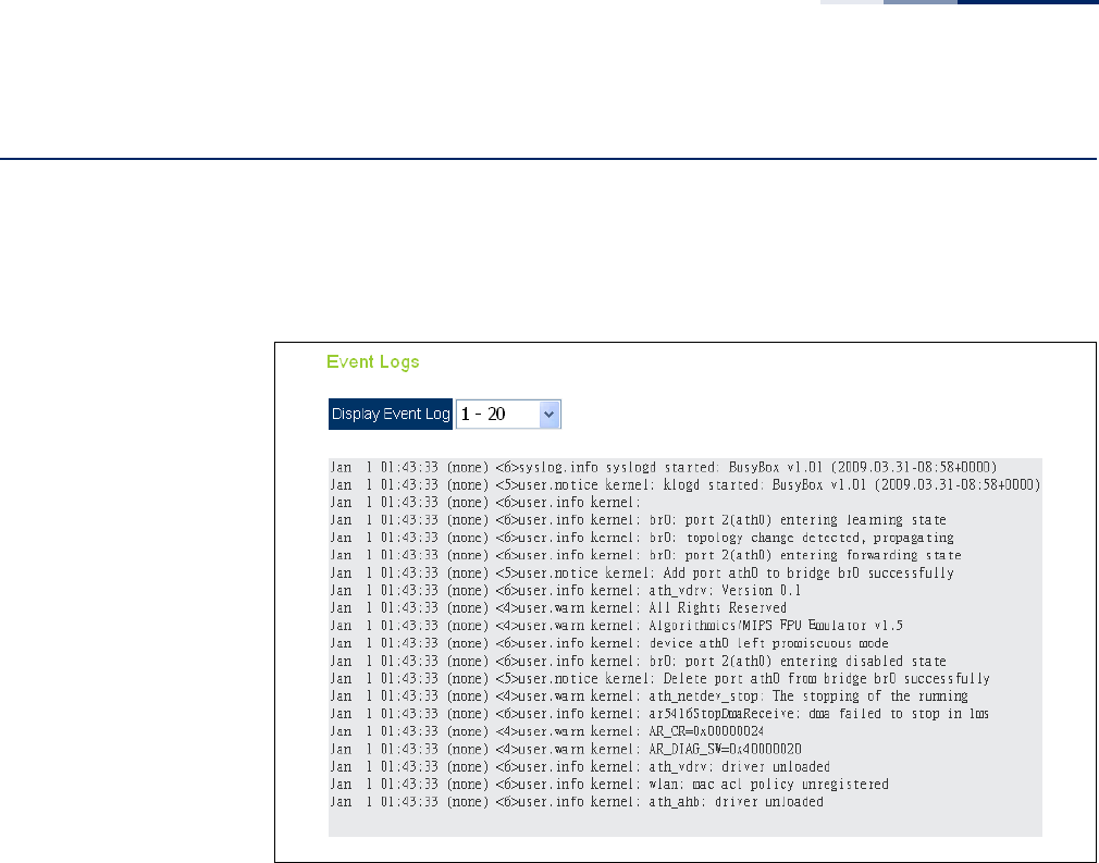
Chapter 8
| Status Information
Event Logs
– 103 –
Event Logs
The Event Logs window shows the log messages generated by the access point and
stored in memory.
Figure 56: Event Logs
The following items are displayed on this page:
◆Display Event Log — Selects the log entries to display. Up to 20 log messages
can be displayed at one time.
Each log entry includes the time the log message was generated, the logging
level associated with the message, and the text of the log message.
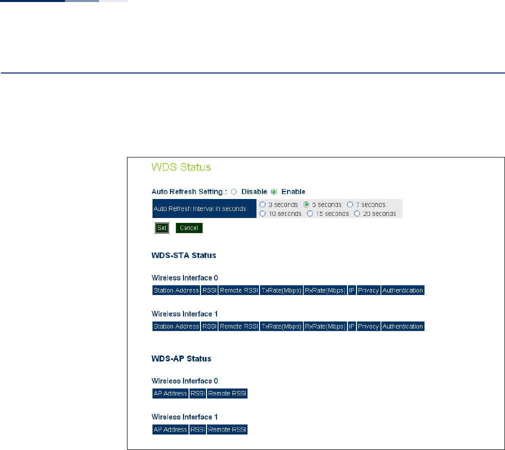
Chapter 8
| Status Information
WDS Status
– 104 –
WDS Status
The WDS Status window shows the WDS information for the 2.4 GHz and 5 GHz
radio interfaces.
Figure 57: WDS Status
The following items are displayed on this page:
◆Auto Refresh Setting — Enables the automatic refresh of WDS status
information. When enabled, you can also set the time interval between each
status refresh.
◆WDS-STA Status — The status of other APs in WDS-STA mode connected to
the AP interfaces.
■Station Address — The MAC address of the AP client.
■RSSI — The Receive Signal Strength Indicator of the received signal sent
from the peer WDS client.
■Remote RSSI — The Receive Signal Strength Indicator of the AP signal
received by the peer WDS-STA client.
■TxRate (Mbps) — The data tranmit rate to the AP client.

Chapter 8
| Status Information
WDS Status
– 105 –
■RxRate (Mbps) — The data receive rate from the AP client.
■IP — The IP address assigned to the AP client.
■Privacy — The data encryption method used by the AP client.
■Authentication — The authentication method used by the AP client.
◆WDS-AP Status — The status of other APs in WDS-AP mode connected to AP
interfaces.
■Station Address — The MAC address of the WDS-enabled AP.
■RSSI — The Receive Signal Strength Indicator of the received signal sent
from the peer WDS AP.
■Remote RSSI — The Receive Signal Strength Indicator of the AP signal
received by the peer WDS-AP.

Chapter 8
| Status Information
WDS Status
– 106 –

– 107 –
Section III
Command Line Interface
This section provides a detailed description of the Command Line Interface, along
with examples for all of the commands.
This section includes these chapters:
◆“Using the Command Line Interface” on page 109
◆“General Commands” on page 115
◆“System Management Commands” on page 119
◆“System Logging Commands” on page 139
◆“System Clock Commands” on page 144
◆“DHCP Relay Commands” on page 149
◆“SNMP Commands” on page 151
◆“Flash/File Commands” on page 164
◆“RADIUS Client Commands” on page 167
◆“802.1X Authentication Commands” on page 173
◆“MAC Address Authentication Commands” on page 175
◆“Filtering Commands” on page 179
◆“Spanning Tree Commands” on page 185
◆“WDS Bridge Commands” on page 197
◆“Ethernet Interface Commands” on page 199
◆“Wireless Interface Commands” on page 206


– 109 –
9Using the Command Line
Interface
When accessing the management interface for the over a direct connection to the
console port, or via a Telnet connection, the access point can be managed by
entering command keywords and parameters at the prompt. Using the access
point’s command-line interface (CLI) is very similar to entering commands on a
UNIX system.
Console Connection
To access the AP through the console port, first set up a console connection to the
AP. See “Console Port Connection” on page 19 for more information.
At the console prompt, enter the user name and password. (The default user name
is “admin” with no default password.) After the password is entered, the CLI displays
the “SMC#” prompt.
Example
(none) login: admin
Password:
Jan 1 11:33:13 login[1918]: root login on 'ttyS0'
SMC#
Note:
Command examples shown later in this chapter abbreviate the console
prompt to “AP” for simplicity.
Enter the necessary commands to complete your desired tasks.
When finished, exit the session with the “exit” command.

Chapter 9
| Using the Command Line Interface
Telnet Connection
– 110 –
Telnet Connection
Telnet operates over the IP transport protocol. In this environment, your
management station and any network device you want to manage over the
network must have a valid IP address. If the access point does not acquire an IP
address from a DHCP server, the default IP address used by the access point is
192.168.2.10.
To access the AP through a Telnet session, you must first set the IP address for the
AP, and set the default gateway if you are managing the AP from a different IP
subnet. For example:
AP#configure
AP(config)#interface ethernet
AP(if-ethernet)#ip address 10.1.0.1 255.255.255.0 10.1.0.254
AP(if-ethernet)#
After you configure the access point with an IP address, you can open a Telnet
session by performing these steps.
1. From the remote host, enter the Telnet command and the IP address of the
device you want to access.
2. At the prompt, enter the user name and system password. The CLI will display
the “AP#” prompt to show that you are using executive access mode (that is,
Exec).
(none) login: admin
Password:
AP#
3. Enter the necessary commands to complete your desired tasks.
4. When finished, exit the session with the “quit” or “exit” command.
Note:
You can open up to four sessions to the device through Telnet.

Chapter 9
| Using the Command Line Interface
Entering Commands
– 111 –
Entering Commands
This section describes how to enter CLI commands.
Keywords and
Arguments
A CLI command is a series of keywords and arguments. Keywords identify a
command, and arguments specify configuration parameters. For example, in the
command “show interfaces ethernet,” show and interfaces are keywords, and
ethernet is an argument that specifies the interface type.
You can enter commands as follows:
◆To enter a simple command, enter the command keyword.
◆To enter commands that require parameters, enter the required parameters
after the command keyword. For example, to set a password for the
administrator, enter:
AP(config)#password admin tpschris
Minimum
Abbreviation
The CLI will accept a minimum number of characters that uniquely identify a
command. For example, the command “configure” can be entered as con. If an
entry is ambiguous, the system will prompt for further input.
Command
Completion
If you terminate input with a Tab key, the CLI will print the remaining characters of a
partial keyword up to the point of ambiguity. In the “configure” example, typing
con followed by a tab will result in printing the command up to “configure.”
Getting Help on
Commands
You can display a brief description of the help system by entering the help
command. You can also display command syntax by following a command with the
“?” character to list keywords or parameters.
Showing Commands If you enter a “?” at the command prompt, the system will display the first level of
keywords for the current configuration mode (Exec, Global Configuration, or
Interface). You can also display a list of valid keywords for a specific command. For
example, the command “show ?” displays a list of possible show commands:
AP# show ?
APmanagement Show management AP information.
authentication Show Authentication parameters.
bridge Show bridge.
config Show current configuration.
event-log Show event log on console.
filters Show filters.
firmware-image Show firmware images version.

Chapter 9
| Using the Command Line Interface
Entering Commands
– 112 –
interface Show interface information.
line TTY line information.
lldp Show lldp parameters.
logging Show the logging buffers.
long-distance Show the outdoor parameter information.
radius Show radius server.
rogue-ap Show Rogue AP information.
snmp Show snmp configuration.
sntp Show sntp configuration.
station Show 802.11 station table.
system Show system information.
version Show system version.
wds Show WDS service.
AP: show
The command “show interface ?” will display the following information:
AP# show interface ?
ethernet Show Ethernet interface
wireless Show Wireless interface
AP# show interface
Negating the Effect of
Commands
For many configuration commands you can enter the prefix keyword “no” to cancel
the effect of a command or reset the configuration to the default value. For
example, the logging command will log system messages to a host server. To
disable logging, specify the no logging command. This guide describes the
negation effect for all applicable commands.
Using Command
History
The CLI maintains a history of commands that have been entered. You can scroll
back through the history of commands by pressing the up arrow key. Any
command displayed in the history list can be executed again, or first modified and
then executed.
Understanding
Command Modes
The command set is divided into Exec and Configuration classes. Exec commands
generally display information on system status or clear statistical counters.
Configuration commands, on the other hand, modify interface parameters or
enable certain functions. These classes are further divided into different modes.
Available commands depend on the selected mode. You can always enter a
question mark “?” at the prompt to display a list of the commands available for the

Chapter 9
| Using the Command Line Interface
Entering Commands
– 113 –
current mode. The command classes and associated modes are displayed in the
following table:
Exec Commands
When you open a new console session on an access point, the system enters Exec
command mode. Only a limited number of the commands are available in this
mode. You can access all other commands only from the configuration mode. To
access Exec mode, open a new console session with the user name “admin.” The
command prompt displays as “AP#” for Exec mode.
(none) login: admin
Password:
[system login password]
AP#
Configuration Commands
Configuration commands are used to modify access point settings. These
commands modify the running configuration and are saved in memory.
The configuration commands are organized into four different modes:
◆Global Configuration (GC) - These commands modify the system level
configuration, and include commands such as system name and password.
◆Interface-Ethernet Configuration (IC-E) - These commands modify the Ethernet
port configuration, and include command such as dns and ip.
◆Interface-Wireless Configuration (IC-W) - These commands modify the wireless
port configuration of global parameters for the radio, and include commands
such as channel and beacon-interval.
◆Interface-Wireless Virtual Access Point Configuration (IC-W-VAP) - These
commands modify the wireless port configuration for each VAP, and include
commands such as ssid and encryption.
To enter the Global Configuration mode, enter the command configure in Exec
mode. The system prompt will change to “AP(config)#” which gives you access
privilege to all Global Configuration commands.
Table 3: Command Modes
Class Mode
Exec Privileged
Configuration Global
Interface-ethernet
Interface-wireless
Interface-wireless-vap

Chapter 9
| Using the Command Line Interface
Entering Commands
– 114 –
AP#configure
AP(config)#
To enter Interface mode, you must enter the “interface ethernet” while in Global
Configuration mode. The system prompt will change to “AP(if-ethernet)#,” or
“AP(if-wireless 0)” indicating that you have access privileges to the associated
commands. You can use the exit command to return to the Exec mode.
AP(config)#interface ethernet
AP(if-ethernet)#
Command Line
Processing
Commands are not case sensitive. You can abbreviate commands and parameters
as long as they contain enough letters to differentiate them from any other
currently available commands or parameters. You can use the Tab key to complete
partial commands, or enter a partial command followed by the “?” character to
display a list of possible matches.

– 115 –
10 General Commands
This chapter details general commands that apply to the CLI.
configure This command activates Global Configuration mode. You must enter this mode to
modify most of the settings on the access point. You must also enter Global
Configuration mode prior to enabling the context modes for Interface
Configuration. See “Using the Command Line Interface” on page 109.
Default Setting
None
Command Mode
Exec
Example
AP#configure
AP(config)#
Related Commands
end
Table 4: General Commands
Command Function Mode Page
configure Activates global configuration mode Exec 115
end Returns to previous configuration mode GC, IC 116
exit Returns to the previous configuration mode, or exits the
CLI any 116
cli-session-timeout Sets a timeout for CLI and Telnet sessions Exec 116
ping Sends ICMP echo request packets to another node on the
network Exec 117
reset Restarts the system Exec 118
show line Shows the configuration settings for the console port Exec 118

Chapter 10
| General Commands
– 116 –
end This command returns to the previous configuration mode.
Default Setting
None
Command Mode
Global Configuration, Interface Configuration
Example
This example shows how to return to the Configuration mode from the Interface
Configuration mode:
AP(if-ethernet)#end
AP(config)#
exit This command returns to the Exec mode or exits the configuration program.
Default Setting
None
Command Mode
Any
Example
This example shows how to return to the Exec mode from the Interface
Configuration mode, and then quit the CLI session:
AP(if-ethernet)#exit
AP#exit
(none) login:
cli-session-timeout This command enables a timeout for console and Telnet sessions.
Syntax
cli-session-timeout <enable | disable | value>
enable - Enables the timeout.
disable - Disables the timeout.
value - Sets a time for the timeout (Range: 60~3600 seconds).
Default Setting
120 seconds

Chapter 10
| General Commands
– 117 –
Command Mode
Exec
Example
The following example disables the CLI timeout.
AP(config)# cli-session-timeout disable
AP(config)#
ping This command sends ICMP echo request packets to another node on the network.
Syntax
ping <host_name | ip_address>
host_name - Alias of the host.
ip_address - IP address of the host.
Default Setting
None
Command Mode
Exec
Command Usage
◆Use the ping command to see if another site on the network can be reached.
◆The following are some results of the ping command:
■Normal response - The normal response occurs in one to ten seconds,
depending on network traffic.
■Destination does not respond - If the host does not respond, a “timeout”
appears in ten seconds.
■Destination unreachable - The gateway for this destination indicates that
the destination is unreachable.
■Network or host unreachable - The gateway found no corresponding entry
in the route table.
Example
AP#ping 192.168.1.19
192.168.1.19 is alive
AP#

Chapter 10
| General Commands
– 118 –
reset This command restarts the system or restores the factory default settings.
Syntax
reset <board | configuration | configuration-keep-ip>
board - Reboots the system.
configuration - Resets the configuration settings to the factory defaults,
and then reboots the system.
configuration-keep-ip - Resets the configuration settings to the factory
defaults except for the IP address, and then reboots the system.
Default Setting
None
Command Mode
Exec
Command Usage
When the system is restarted, it will always run the Power-On Self-Test.
Example
This example shows how to reset the system:
AP#reset board
Please wait a moment...
show line This command displays the console port’s configuration settings.
Command Mode
Exec
Example
The console port settings are fixed at the values shown below.
AP#show line
Console Line Information
======================================================
databits : 8
parity : none
speed : 115200
stop bits : 1
======================================================
AP#

– 119 –
11 System Management
Commands
These commands are used to configure the password, system logs, browser
management options, clock settings, and a variety of other system information.
Table 5: System Management Commands
Command Function Mode Page
country Sets the access point country code Exec 120
prompt Customizes the command line prompt GC 121
system name Specifies the host name for the access point GC 122
system-resource Sets rising and falling CPU and memory thresholds GC 122
password Specifies the password for management access GC 123
reboot-schedule Restarts the AP after a specified time GC 124
apmgmtui ssh enable Enables the Secure Shell server GC 124
apmgmtui ssh port Sets the Secure Shell port GC 125
ip telnet-server enable Enables the Telnet server GC 125
apmgmtip Specifies an IP address or range of addresses allowed
access to management interfaces GC 129
apmgmtui telnet-
server Enables Telnet management access GC 125
apmgmtui snmp Enables SNMP management access GC 129
apmgmtui http port Specifies the port to be used by the web browser
interface GC 126
apmgmtui http server Allows the access point to be monitored or configured
from a browser GC 126
apmgmtui http
session-timeout Sets the web interface timeout GC 127
apmgmtui https port Specifies the UDP port number used for a secure HTTP
connection to the access point’s Web interface GC 127
apmgmtui https
server Enables the secure HTTP server on the access point GC 128
show apmanagement Shows the AP management configuration Exec 130
show system Displays system information Exec 130
show system resource Displays CPU and memory usage information Exec 131

Chapter 11
| System Management Commands
– 120 –
country This command configures the access point’s country code, which identifies the
country of operation and sets the authorized radio channels.
Syntax
country <country_code>
country_code - A two character code that identifies the country of
operation. See the following table for a full list of codes.
show version Displays version information for the system Exec 132
show config Displays detailed configuration information for the
system Exec 132
Table 5: System Management Commands (Continued)
Command Function Mode Page
Table 6: Country Codes
Country Code Country Code Country Code Country Code
Albania AL Dominican
Republic DO Kuwait KW Romania RO
Algeria DZ Ecuador EC Latvia LV Russia RU
Argentina AR Egypt EG Lebanon LB Saudi Arabia SA
Armenia AM Estonia EE Liechtenstein LI Singapore SG
Australia AU Finland FI Lithuania LT Slovak
Republic SK
Austria AT France FR Macao MO Spain ES
Azerbaijan AZ Georgia GE Macedonia MK Sweden SE
Bahrain BH Germany DE Malaysia MY Switzerland CH
Belarus BY Greece GR Malta MT Syria SY
Belgium BE Guatemala GT Mexico MX Taiwan TW
Honduras HN Monaco MC Thailand TH
Belize BZ Hong Kong HK Morocco MA Trinidad &
Tobago TT
Bolivia BO Hungary HU Netherlands NL Tunisia TN
Brazil BR Iceland IS New Zealand NZ Turkey TR
Brunei
Darussalam BN India IN Norway NO Ukraine UA
Bulgaria BG Indonesia ID Qatar QA United Arab
Emirates AE
Canada CA Iran IR Oman OM United
Kingdom GB
Chile CL Ireland IE Pakistan PK United States US

Chapter 11
| System Management Commands
– 121 –
Default Setting
US - for units sold in the United States
99 (no country set) - for units sold in other countries
Command Mode
Exec
Command Usage
◆If you purchased an access point outside of the United States, the country code
must be set before radio functions are enabled.
◆The available Country Code settings can be displayed by using the country ?
command.
Example
AP#country tw
AP#
prompt This command customizes the CLI prompt. Use the no form to restore the default
prompt.
Syntax
prompt <string>
no prompt
string - Any alphanumeric string to use for the CLI prompt.
(Maximum length: 32 characters)
China CN Israel IL Panama PA Uruguay UY
Colombia CO Italy IT Peru PE Uzbekistan UZ
Costa Rica CR Japan JP Philippines PH Yemen YE
Croatia HR Jordan JO Poland PL Venezuela VE
Cyprus CY Kazakhstan KZ Portugal PT Vietnam VN
Czech
Republic CZ North Korea KP Puerto Rico PR Zimbabwe ZW
Denmark DK Korea
Republic KR Slovenia SI
Elsalvador SV Luxembourg LU South Africa ZA
Table 6: Country Codes (Continued)
Country Code Country Code Country Code Country Code

Chapter 11
| System Management Commands
– 122 –
Default Setting
Enterprise AP
Command Mode
Global Configuration
Example
AP(config)#prompt RD2
RD2(config)#
system name This command specifies or modifies the system name for this device.
Syntax
system name <name>
name - The name of this host.
(Maximum length: 32 characters)
Default Setting
Enterprise AP
Command Mode
Global Configuration
Example
AP(config)#system name AP
AP(config)#
system-resource This command sets CPU and memory rising and falling thresholds that monitor
system resources.
Syntax
system-resource threshold <cpu-rising> <cpu-falling> <memory-rising>
<memory-falling> <interval>
threshold - Keyword that sets CPU and memory threshold values.
cpu-rising - The CPU utilization rising threshold as a percentage.
(Range: 1-100 percent, 0 is disabled)
cpu-falling - The CPU utilization falling threshold as a percentage.
(Range: 0 to less than the CPU rising threshold)
memory-rising - The memory utilization rising threshold in Kbytes.
(Range: 1-113076 Kbytes, 0 is disabled)

Chapter 11
| System Management Commands
– 123 –
memory-falling - The memory utilization falling threshold in Kbytes.
(Range: 0 to less than the memory rising threshold)
interval - The utilization check interval in seconds.
(Range: 1 to 86400 seconds, 0 is disabled)
Default Setting
CPU Rising Threshold: 0 (disabled)
CPU Falling Threshold: 20 percent
Memory Rising Threshold: 0 (disabled)
Memory Falling Threshold: 16000 Kbytes
Threshold Interval: 0 (disabled)
Command Mode
Global Configuration
Command Usage
◆When the CPU rising threshold is exceeded, a “CPU Busy” SNMP trap message is
sent (only sent once). When the CPU utilization then drops below the falling
threshold, a “CPU Free” trap message is sent .
◆When the memory rising threshold is exceeded, a “Memory Overload” SNMP
trap message is sent (only sent once). When the memory utilization then drops
below the falling threshold, a “Memory Free” trap message is sent .
Example
AP(config)# system-resource threshold 80 20 100000 16000 20
AP(config)#
password After initially logging onto the system, you should set the access passwords.
Remember to record them in a safe place.
Syntax
password <admin | guest> <old-password> <new-password>
admin - The keyword for the administrator password.
guest - The keyword for the guest password
old-password - The current password for management access. When there
is no password set, enter the string “null”.
(Length: 5-32 characters, case sensitive)
new-password - The new password for management access.
(Length: 5-32 characters, case sensitive)

Chapter 11
| System Management Commands
– 124 –
Default Setting
None. There are no admin or guest passwords.
Command Mode
Global Configuration
Example
AP(config)#password admin null tpschris
AP(config)#
reboot-schedule This command restarts the system after a scheduled time.
Syntax
reboot-schedule {fixed-time <day><hour><minutes> | countdown
<minutes> | disable}
fixed-time - Reboots after a specified time in days, hours, and minutes.
countdown - Reboots after a specified coundown time in minutes.
disable - Disables the reboot schedule.
Default Setting
Disabled
Command Mode
Global Configuration
Command Usage
When the system is restarted, it will always run the Power-On Self-Test.
Example
This example shows how to set a scheduled reboot time:
AP(config)# reboot-schedule fixed-time 1 2 3
AP(config)#
apmgmgtui ssh
enable
This command enables the Secure Shell server. Use the no form to disable the
server.
Syntax
apmgmtui ssh enable
no apmgmtui ssh-server

Chapter 11
| System Management Commands
– 125 –
Default Setting
Enabled
Command Mode
Global Configuration
Command Usage
◆The access point supports Secure Shell version 2.0 only.
◆After boot up, the SSH server needs about two minutes to generate host
encryption keys. The SSH server is disabled while the keys are being generated.
The show system command displays the status of the SSH server.
Example
AP(config)# apmgmtui ssh enable
AP(config)#
apmgmtui ssh port This command sets the Secure Shell server port.
Syntax
apmgmtui ssh port <port-number>
port-number - The UDP port used by the SSH server.
(Range: 1-65535)
Default Setting
22
Command Mode
Global Configuration
Example
AP(config)# apmgmtui ssh port 1124
AP(config)#
apmgmtui telnet-
server enable
This command enables the Telnet server. Use the no form to disable the server.
Syntax
apmgmtui telnet-server enable
no apmgmtui telnet-server

Chapter 11
| System Management Commands
– 126 –
Default Setting
Interface enabled
Command Mode
Global Configuration
Example
AP(config)# apmgmtui telnet-server enable
AP(config)#
apmgmtui http port This command specifies the TCP port number used by the web browser interface.
Use the no form to use the default port.
Syntax
apmgmtui http port <port-number>
no apmgmtui http port
port-number - The TCP port to be used by the browser interface. (Range: 80
or 1024-65535)
Default Setting
80
Command Mode
Global Configuration
Example
AP(config)# apmgmtui http port 769
AP(config)
Related Commands
apmgmtui http server
apmgmtui http server This command allows this device to be monitored or configured from a web
browser. Use the no form to disable this function.
Syntax
[no] apmgmtui http server
Default Setting
Enabled

Chapter 11
| System Management Commands
– 127 –
Command Mode
Global Configuration
Example
AP(config)# apmgmtui http server
AP(config)#
Related Commands
apmgmtui http port
apmgmtui http
session-timeout
This command sets the web browser timeout limit.
Syntax
apmgmtui http session-timeout <seconds>
seconds - The web session timeout. (Range: 0-1800 seconds, 0 means
disabled)
Default Setting
1800 seconds
Command Mode
Global Configuration
Example
AP(config)# apmgmtui http session-timeout 0
AP(config)#
Related Commands
apmgmtui http server
apmgmtui https port Use this command to specify the UDP port number used for HTTPS/SSL connection
to the access point’s web interface. Use the no form to restore the default port.
Syntax
apmgmtui https port <port_number>
no apmgmtui https port
port_number – The UDP port used for HTTPS/SSL.
(Range: 443, 1024-65535)
Default Setting
443

Chapter 11
| System Management Commands
– 128 –
Command Mode
Global Configuration
Command Usage
◆You cannot configure the HTTP and HTTPS servers to use the same port.
◆To avoid using common reserved TCP port numbers below 1024, the
configurable range is restricted to 443 and between 1024 and 65535.
◆If you change the HTTPS port number, clients attempting to connect to the
HTTPS server must specify the port number in the URL, in this format: https://
device:port_number
Example
AP(config)# apmgmtui https port 1234
AP(config)#
apmgmtui https
server
Use this command to enable the secure hypertext transfer protocol (HTTPS) over
the Secure Socket Layer (SSL), providing secure access (that is, an encrypted
connection) to the access point’s web interface. Use the no form to disable this
function.
Syntax
[no] apmgmtui https server
Default Setting
Enabled
Command Mode
Global Configuration
Command Usage
◆Both HTTP and HTTPS service can be enabled independently.
◆If you enable HTTPS, you must indicate this in the URL:
https://device:port_number]
◆When you start HTTPS, the connection is established in this way:
■The client authenticates the server using the server’s digital certificate.
■The client and server negotiate a set of security protocols to use for the
connection.
■The client and server generate session keys for encrypting and decrypting
data.

Chapter 11
| System Management Commands
– 129 –
■The client and server establish a secure encrypted connection.
A padlock icon should appear in the status bar for Internet Explorer.
Example
AP(config)# apmgmtui https server
AP(config)#
apmgmtui snmp This command enables and disables SNMP management access to the AP.
Syntax
apmgmtui snmp [enable | disable]
enable - Enables SNMP management access.
disable - Disables SNMP management access.
Default Setting
Enabled
Command Mode
Global Configuration
Example
AP(config)# apmgmtui snmp enable
AP(config)#
apmgmtip This command specifies the client IP addresses that are allowed management
access to the access point through various protocols.
Note:
Secure Web (HTTPS) connections are not affected by the UI Management or
IP Management settings.
Syntax
apmgmtip [multiple <ip-address> <subnet-mask> | single <ip-address> | any]
multiple - Adds IP addresses within a specifiable range to the SNMP, web
and Telnet groups.
single - Adds an IP address to the SNMP, web and Telnet groups.
any - Allows any IP address access through SNMP, web and Telnet groups.
ip-address - Adds IP addresses to the SNMP, web and Telnet groups.

Chapter 11
| System Management Commands
– 130 –
subnet-mask - Specifies a range of IP addresses allowed management
access.
Default Setting
All addresses
Command Mode
Global Configuration
Command Usage
◆If anyone tries to access a management interface on the access point from an
invalid address, the unit will reject the connection, enter an event message in
the system log, and send a trap message to the trap manager.
◆Management access applies to SNMP, HTTP (web), Telnet, and SSH connections.
Example
This example restricts management access to the specified addresses.
AP(config)#apmgmtip multiple 192.168.1.50 255.255.255.0
AP(config)#
show apmanagement This command shows the AP management configuration, including the IP
addresses of management stations allowed to access the AP, and the protocols that
are open to management access.
Command Mode
Exec
Example
AP#show apmanagement
=================================
AP Management IP Mode: static
Telnet UI: Enable
WEB UI : Enable
SNMP UI : Enable
==================================
AP#
show system This command displays basic system configuration settings.
Command Mode
Exec

Chapter 11
| System Management Commands
– 131 –
Example
AP#show system
System Information
==============================================================
Serial Number : AC25123456
System Up time : 1 min
System Name : SMC2891W-AN
System Location : where?
System Contact : who?
System Country Code : TW - Taiwan
MAC Address : 70:72:CF:00:11:70
Radio 0 MAC Address : 70:72:CF:00:11:70
Radio 1 MAC Address : 70:72:CF:00:11:80
IP Address : 192.168.2.10
Subnet Mask : 255.255.255.0
Default Gateway : 192.168.2.254
Management IP : 192.168.1.10
Management Subnet : 255.255.255.0
IPv6 Address : 2001:db8::1
IPv6 Subnet Mask : 64
IPv6 Gateway : 2001:db8::2
VLAN Status : Disable
Management VLAN ID(AP): 4093
Native VLAN ID(AP) : 1
DHCP Client : static
HTTP Access : Enable
HTTP Port : 80
HTTP Timeout : 1800
HTTPs Access : Enable
HTTPs Port : 443
SSH Access : Enable
SSH Port : 22
Telnet Access : Enable
Telnet Port : 23
Slot Status : Dual band(a/g)
Boot Rom Version : U-Boot 1.1.4 r1.4
Software Version : 0.3.3.4
Hardware Version : R0b
Part Number :
Production Date : 2012/06/01
User Name : admin
Reboot scheduling : disable
==============================================================
AP#
show system resource This command displays CPU and memory usage information for the system.
Command Mode
Exec
Example
AP#show system resource
=============== CPU =========================================
user (%) 0.00
nice (%) 0.00
system (%) 7.92

Chapter 11
| System Management Commands
– 132 –
iowait (%) 0.00
idle (%) 92.08
=============== Memory ======================================
free (kb) 95820
used (kb) 17256
used (%) 15.26
cached (kb) 4900
=============================================================
AP#
show version This command displays the software version for the system.
Command Mode
Exec
Example
AP#show version
Boot Rom Version : U-Boot 1.1.4 r1.4
Software Version : 0.3.3.4
Hardware Version : R0b
AP#
show config This command displays detailed configuration information for the system.
Command Mode
Exec
Example
AP#show config
System Information
==============================================================
Serial Number : AC25123456
System Up time : 1 min
System Name : SMC2891W-AN
System Location : where?
System Contact : who?
System Country Code : TW - Taiwan
MAC Address : 70:72:CF:00:11:70
Radio 0 MAC Address : 70:72:CF:00:11:70
Radio 1 MAC Address : 70:72:CF:00:11:80
IP Address : 192.168.2.10
Subnet Mask : 255.255.255.0
Default Gateway : 192.168.2.254
Management IP : 192.168.1.10
Management Subnet : 255.255.255.0
IPv6 Address : 2001:db8::1
IPv6 Subnet Mask : 64
IPv6 Gateway : 2001:db8::2
VLAN Status : Disable
Management VLAN ID(AP): 4093
Native VLAN ID(AP) : 1
DHCP Client : static

Chapter 11
| System Management Commands
– 133 –
HTTP Access : Enable
HTTP Port : 80
HTTP Timeout : 1800
HTTPs Access : Enable
HTTPs Port : 443
SSH Access : Enable
SSH Port : 22
Telnet Access : Enable
Telnet Port : 23
Slot Status : Dual band(a/g)
Boot Rom Version : U-Boot 1.1.4 r1.4
Software Version : 0.3.3.4
Hardware Version : R0b
Part Number :
Production Date : 2012/06/01
User Name : admin
Reboot scheduling : disable
==============================================================
SVP Information
==============================================================
SVP: Enabled
==============================================================
SNTP Information
===========================================================
Service State : ENABLED
SNTP (server 1) IP : 129.6.15.28
SNTP (server 2) IP : 132.163.4.101
Current Time : Thu Jan 1 08:07:56 CST 1970
Time Zone : (GMT+08) Taiwan : Taipei
Daylight Saving : DISABLED
Daylight Saving Time : From MAR, Fourth Week, Wednesday To NOV, Last Week,
Sunday
===========================================================
SNMP Information
==============================================
Service State : Enable
Community (ro) : *******
Community (rw) : ********
Location : where?
Contact : who?
==============================================
Trap Destination List:
==============================================
There is no SNMP Trap Host.
==============================================
Trap Configuration:
==========================================================================
systemUp: Disabled systemDown: Disabled
==========================================================================
View List:
==================================
There is no view.
==================================
Group List:
==================================

Chapter 11
| System Management Commands
– 134 –
There is no group.
==================================
User List:
==================================
There is no SNMPv3 User.
==================================
Target List:
==================================
There is no SNMP target.
==================================
Filter List:
==================================
There is no notification filter.
==================================
Bridge STP Information
==================================
Bridge MAC : 70:72:CF:00:11:70
Status : Disabled
priority : 32768
Hello Time : 2 seconds
Maximum Age : 20 seconds
Forward Delay : 15 seconds
==================================
Bridge Aging Time Information
==============================================================
Aging time: 20
==============================================================
Logging Information
=====================================================
Syslog State : DISABLE
Logging Console State : DISABLE
Logging Level : Debug
Servers
1: 10.7.16.98, UDP Port: 514, State: DISABLE
2: 10.7.13.48, UDP Port: 514, State: DISABLE
3: 10.7.123.123, UDP Port: 514, State: DISABLE
4: 10.7.13.77, UDP Port: 514, State: DISABLE
=====================================================
Protocol Filter Information
=======================================================================
Local Bridge :DISABLED
access-limitation :DISABLED
dhcp :DISABLED
EtherType Filter :DISABLED
Enabled EtherType Filters
-----------------------------------------------------------------------
=======================================================================
ACL Information
==========================================
Source Filter :DISABLED
Source MAC :
==========================================
ACL Information
==========================================

Chapter 11
| System Management Commands
– 135 –
Destination Filter :DISABLED
Destination MAC :
==========================================
Console Line Information
===========================================================
databits : 8
parity : none
speed : 115200
stop bits : 1
===========================================================
Ethernet Interface Information
========================================
IP Address : 192.168.2.10
Subnet Mask : 255.255.255.0
Default Gateway : 192.168.2.254
Primary DNS :
Secondary DNS :
IPv6 Address : 2001:db8::1
IPv6 Subnet Mask : 64
IPv6 Gateway : 2001:db8::2
IPv6 Primary DNS :
IPv6 Secondary DNS :
Admin status : Up
Operational status : Up
========================================
-------------------------------Basic Setting-------------------------------
SSID : EAP9112A_11BGN_0
Wireless Network Mode : 11ng
Auto Channel Select : DISABLE
Channel : 6
High Throughput Mode : HT20
Allowed Rates :
1,2,5.5,6,9,11,12,18,24,36,48,54,MCS0,MCS1,MCS2,MCS3,MCS4,MCS5,MCS6,MCS7,MC
S8,MCS9,MCS10,MCS11,MCS12,MCS13,MCS14,MCS15
Status : ENABLE
MAC Address : 70:72:CF:00:11:70
VLAN-ID : 1
Dhcp-Relay Server Ip : 0.0.0.0
---------------------------------Capacity----------------------------------
Maximum Association Client Per Vap : 16 Clients
Maximum Association Client Per Radio : 127 Clients
-----------------------------802.11 Parameters-----------------------------
Transmit Power : 100%(Tx dBm)
Preamble Length : Short-or-Long
Fragmentation Threshold : 2346
RTS Threshold : 2346
Beacon Interval : 100
Authentication Timeout Interval : 3 Mins
Association Timeout Interval : 5 Mins
DTIM Interval : 1
Short Guard Interval Status : Disabled
A-MPDU Status : Enabled
A-MPDU Length Limit : 65535 Bytes
A-MSDU Status : Enabled
Disable HT20/H40 coexistence : n
---------------------------------Security----------------------------------
Closed System : DISABLE
WPA Function : OPEN-SYSTEM, WPA FUNCTION DISABLE

Chapter 11
| System Management Commands
– 136 –
WPA PSK Key Type : ascii
WPA PSK Key : ********
Default Transmit Key : 1
Static WEP Keys
Key 1 : *****
Key 2 : *****
Key 3 : *****
Key 4 : *****
Pre-Authentication : DISABLE
----------------------------------802.1x-----------------------------------
802.1x : DISABLE
802.1x Reauthentication Time Value : 3600 seconds
--------------------Bandwidth Control for Uplink/Downlink------------------
Bandwidth Control for Uplink : DISABLE
Bandwidth Control for Uplink rate : 100 Kbyte/s
Bandwidth Control for Downlink : DISABLE
Bandwidth Control for Downlink rate : 100 Kbyte/s
-------------------------------Qos Mapping-------------------------------
Qos Mapping for vap to 802.1p : DISABLE
User Priority for vap to 802.1p : 0
Qos Mapping for 802.1d to 802.1p : DISABLE
Template Name for 802.1d to 802.1p : default_up_mapping_1
Template Priority for 802.1d to 802.1p : 01234567
Qos Mapping for 802.1d to DSCP : DISABLE
Template Name for 802.1d to DSCP : default_up_mapping_1
Template Priority for 802.1d to DSCP : 01234567
-----------------------------Quality of Service----------------------------
WMM Mode : ENABLED
WMM Acknowledge Policy
AC0(BE) : Acknowledge
AC1(BK) : Acknowledge
AC2(VI) : Acknowledge
AC3(VO) : Acknowledge
WMM AP Parameters:
AC0(BE) CwMin: 4 CwMax: 6 AIFSN: 3 TXOP Limit: 0
AC1(BK) CwMin: 4 CwMax: 10 AIFSN: 7 TXOP Limit: 0
AC2(VI) CwMin: 3 CwMax: 4 AIFSN: 1 TXOP Limit:3008
AC3(VO) CwMin: 2 CwMax: 3 AIFSN: 1 TXOP Limit:1504
WMM BSS Parameters:
AC0(BE) CwMin: 4 CwMax: 10 AIFSN: 3 TXOP Limit: 0 ACM:Disabled
AC1(BK) CwMin: 4 CwMax: 10 AIFSN: 7 TXOP Limit: 0 ACM:Disabled
AC2(VI) CwMin: 3 CwMax: 4 AIFSN: 2 TXOP Limit:3008 ACM:Disabled
AC3(VO) CwMin: 2 CwMax: 3 AIFSN: 2 TXOP Limit:1504 ACM:Disabled
-------------------------------Basic Setting-------------------------------
SSID : SMC2891W-AN_11NA_0
Wireless Network Mode : 11na
Auto Channel Select : DISABLE
Channel : 56
High Throughput Mode : HT20
Allowed Rates :
1,2,5.5,6,9,11,12,18,24,36,48,54,MCS0,MCS1,MCS2,MCS3,MCS4,MCS5,MCS6,MCS7,MC
S8,MCS9,MCS10,MCS11,MCS12,MCS13,MCS14,MCS15
Status : ENABLE
MAC Address : 70:72:CF:00:11:80
VLAN-ID : 1
Dhcp-Relay Server Ip : 0.0.0.0
---------------------------------Capacity----------------------------------
Maximum Association Client Per Vap : 16 Clients

Chapter 11
| System Management Commands
– 137 –
Maximum Association Client Per Radio : 127 Clients
-----------------------------802.11 Parameters-----------------------------
Transmit Power : 100%(Tx dBm)
Fragmentation Threshold : 2346
RTS Threshold : 2346
Beacon Interval : 100
Authentication Timeout Interval : 3 Mins
Association Timeout Interval : 5 Mins
DTIM Interval : 1
Short Guard Interval Status : Disabled
A-MPDU Status : Enabled
A-MPDU Length Limit : 65535 Bytes
A-MSDU Status : Enabled
Disable HT20/H40 coexistence : n
---------------------------------Security----------------------------------
Closed System : DISABLE
WPA Function : OPEN-SYSTEM, WPA FUNCTION DISABLE
WPA PSK Key Type : ascii
WPA PSK Key : ********
Default Transmit Key : 1
Static WEP Keys
Key 1 : *****
Key 2 : *****
Key 3 : *****
Key 4 : *****
Pre-Authentication : DISABLE
----------------------------------802.1x-----------------------------------
802.1x : DISABLE
802.1x Reauthentication Time Value : 3600 seconds
-------------------Bandwidth Control for Uplink/Downlink-------------------
Bandwidth Control for Uplink : DISABLE
Bandwidth Control for Uplink rate : 100 Kbyte/s
Bandwidth Control for Downlink : DISABLE
Bandwidth Control for Downlink rate : 100 Kbyte/s
-------------------------------Qos Mapping-------------------------------
Qos Mapping for vap to 802.1p : DISABLE
User Priority for vap to 802.1p : 0
Qos Mapping for 802.1d to 802.1p : DISABLE
Template Name for 802.1d to 802.1p : default_up_mapping_1
Template Priority for 802.1d to 802.1p : 01234567
Qos Mapping for 802.1d to DSCP : DISABLE
Template Name for 802.1d to DSCP : default_up_mapping_1
Template Priority for 802.1d to DSCP : 01234567
-----------------------------Quality of Service----------------------------
WMM Mode : ENABLED
WMM Acknowledge Policy
AC0(BE) : Acknowledge
AC1(BK) : Acknowledge
AC2(VI) : Acknowledge
AC3(VO) : Acknowledge
WMM AP Parameters:
AC0(BE) CwMin: 4 CwMax: 6 AIFSN: 3 TXOP Limit: 0
AC1(BK) CwMin: 4 CwMax: 10 AIFSN: 7 TXOP Limit: 0
AC2(VI) CwMin: 3 CwMax: 4 AIFSN: 1 TXOP Limit:3008
AC3(VO) CwMin: 2 CwMax: 3 AIFSN: 1 TXOP Limit:1504
WMM BSS Parameters:

Chapter 11
| System Management Commands
– 138 –
AC0(BE) CwMin: 4 CwMax: 10 AIFSN: 3 TXOP Limit: 0 ACM:Disabled
AC1(BK) CwMin: 4 CwMax: 10 AIFSN: 7 TXOP Limit: 0 ACM:Disabled
AC2(VI) CwMin: 3 CwMax: 4 AIFSN: 2 TXOP Limit:3008 ACM:Disabled
AC3(VO) CwMin: 2 CwMax: 3 AIFSN: 2 TXOP Limit:1504 ACM:Disabled
LLDP Information
===================================================================
Status :Disabled
Message Transmission Hold Time :4
Message Transmission Interval (seconds) :30
Reinitial Delay Time (seconds) :2
Transmission Delay Value (seconds) :2
===================================================================
Radius Accounting Information
==============================================
Status : DISABLED
IP : 10.7.16.96
Shared Secret : ********
Port : 1813
timeout-interim : 300
==============================================
Radius Primary Server Information
==============================================
Status : ENABLED
IP : 10.7.16.96
Port : 1812
Shared Secret : ********
==============================================
Radius Secondary Server Information
==============================================
Status : ENABLED
IP : 10.7.16.96
Port : 1812
Shared Secret : ***
==============================================
AP#

– 139 –
12 System Logging Commands
These commands are used to configure system logging on the access point.
logging on This command controls logging of error messages; i.e., sending debug or error
messages to memory. The no form disables the logging process.
Syntax
[no] logging on
Default Setting
Disabled
Command Mode
Global Configuration
Command Usage
The logging process controls error messages saved to memory. You can use the
logging level command to control the type of error messages that are stored in
memory.
Example
AP(config)#logging on
AP(config)#
Table 7: System Management Commands
Command Function Mode Page
logging on Controls logging of error messages GC 139
logging host Adds a syslog server host IP address that will receive
logging messages GC 140
logging console Initiates logging of error messages to the console GC 140
logging level Defines the minimum severity level for event logging GC 141
logging clear Clears all log entries in access point memory GC 141
show logging Displays the state of logging Exec 142
show event-log Displays all log entries in access point memory Exec 142

Chapter 12
| System Logging Commands
– 140 –
logging host This command specifies syslog servers host that will receive logging messages. Use
the no form to remove syslog server host.
Syntax
logging host <1 | 2 | 3 | 4> <host_name | host_ip_address> [udp_port]
no logging host <1 | 2 | 3 | 4>
1 - First syslog server.
2 - Second syslog server.
3 - Third syslog server.
4 - Fourth syslog server.
host_name - The name of a syslog server. (Range: 1-20 characters)
host_ip_address - The IP address of a syslog server.
udp_port - The UDP port used by the syslog server.
Default Setting
None
Command Mode
Global Configuration
Example
AP(config)#logging host 1 10.1.0.3
AP(config)#
logging console This command initiates logging of error messages to the console. Use the no form
to disable logging to the console.
Syntax
[no] logging console
Default Setting
Disabled
Command Mode
Global Configuration
Example
AP(config)#logging console
AP(config)#

Chapter 12
| System Logging Commands
– 141 –
logging level This command sets the minimum severity level for event logging.
Syntax
logging level <Emergency | Alert | Critical | Error | Warning | Notice |
Informational | Debug>
Default Setting
Informational
Command Mode
Global Configuration
Command Usage
Messages sent include the selected level down to Emergency level.
Example
AP(config)#logging level alert
AP(config)#
logging clear This command clears all log messages stored in the access point’s memory.
Syntax
logging clear
Command Mode
Global Configuration
Table 8: Logging Levels
Level Argument Description
Emergency System unusable
Alert Immediate action needed
Critical Critical conditions (e.g., memory allocation, or free memory error -
resource exhausted)
Error Error conditions (e.g., invalid input, default used)
Warning Warning conditions (e.g., return false, unexpected return)
Notice Normal but significant condition, such as cold start
Informational Informational messages only
Debug Debugging messages

Chapter 12
| System Logging Commands
– 142 –
Example
AP(config)#logging clear
AP(config)#
show logging This command displays the logging configuration.
Syntax
show logging
Command Mode
Exec
Example
AP#show logging
Logging Information
=====================================================
Syslog State : ENABLE
Logging Console State : DISABLE
Logging Level : Debug
Servers
1: 10.7.16.98, UDP Port: 514, State: DISABLE
2: 10.7.13.48, UDP Port: 514, State: DISABLE
3: 10.7.123.123, UDP Port: 65535, State: DISABLE
4: 10.7.13.77, UDP Port: 5432, State: DISABLE
=====================================================
AP#
show event-log This command displays log messages stored in the access point’s memory.
Syntax
show event-log
Command Mode
Exec
Example
AP#show event-log
Jan 1 05:45:50 (none) <6>user.info kernel: ar5416Reset Setting CFG 0x10a
Jan 1 05:45:50 (none) <6>user.info kernel: Howl Revision ID 0xb9
Jan 1 05:45:50 (none) <6>user.info kernel: ar5416Reset Setting CFG 0x10a
Jan 1 05:45:50 (none) <6>user.info kernel: Howl Revision ID 0xb9
Jan 1 05:45:50 (none) <6>user.info kernel: MBSSID Set bit 22 of AR_STA_ID
0xb8c1817b
Jan 1 05:45:50 (none) <6>user.info kernel: Force rf_pwd_icsyndiv to 2 on 2462
(1 0)

Chapter 12
| System Logging Commands
– 143 –
AP#

– 144 –
13 System Clock Commands
These commands are used to configure SNTP and system clock settings on the
access point.
sntp-server ip This command sets the IP address of the servers to which SNTP time requests are
issued. Use the this command with no arguments to clear all time servers from the
current list.
Syntax
sntp-server ip <1 | 2> <ip>
1 - First time server.
2 - Second time server.
ip - IP address of an time server (NTP or SNTP).
Default Setting
129.6.15.28
132.163.4.101
Command Mode
Global Configuration
Command Usage
When SNTP client mode is enabled using the sntp-server enabled command, the
sntp-server ip command specifies the time servers from which the access point
polls for time updates. The access point will poll the time servers in the order
specified until a response is received.
Table 9: System Clock Commands
Command Function Mode Page
sntp-server ip Specifies one or more time servers GC 144
sntp-server enabled Accepts time from the specified time servers GC 145
sntp-server date-time Manually sets the system date and time GC 145
sntp-server daylight-saving Sets the start and end dates for daylight savings
time GC 146
sntp-server timezone Sets the time zone for the access point’s internal
clock GC 147
show sntp Shows current SNTP configuration settings Exec 147

Chapter 13
| System Clock Commands
– 145 –
Example
AP(config)#sntp-server ip 1 10.1.0.19
AP#
Related Commands
sntp-server enabled
show sntp
sntp-server enabled This command enables SNTP client requests for time synchronization with NTP or
SNTP time servers specified by the sntp-server ip command. Use the no form to
disable SNTP client requests.
Syntax
[no] sntp-server enabled
Default Setting
Enabled
Command Mode
Global Configuration
Command Usage
The time acquired from time servers is used to record accurate dates and times for
log events. Without SNTP, the access point only records the time starting from the
factory default set at the last bootup (i.e., 00:14:00, January 1, 1970).
Example
AP(config)#sntp-server enabled
AP(config)#
Related Commands
sntp-server ip
show sntp
sntp-server date-time This command sets the system clock.
Syntax
sntp-server <year> <month> <day> <hour> <minute>
year - Sets the year. (Range: 1970-2100)
month - Sets the month. (Range: 1-12)
day - Sets the day. (Range: 1-31)

Chapter 13
| System Clock Commands
– 146 –
hour - Sets the hour. (Range: 0-23)
minute - Sets the minute. (Range: 0-59)
Default Setting
00:14:00, January 1, 1970
Command Mode
Global Configuration
Example
This example sets the system clock to 12:10 April 27, 2009.
AP(config)# sntp-server date-time 2009 4 27 12 10
AP(config)#
Related Commands
sntp-server enabled
sntp-server daylight-
saving
This command sets the start and end dates for daylight savings time. Use the no
form to disable daylight savings time.
Syntax
sntp-server daylight-saving [date-week <start-month> <start-week> <start-
day> <end-month> <end-week> <end-day>]
no sntp-server daylight-saving
date-week - The key word to set the date on which to start and end the
daylight-saving time.
start-month - Sets the start month. (Range: 1-12)
start-week - Sets the start week. (Range: 1-5)
start-day - Sets the start day. (Range: 0-6, where 0 is Sunday)
end-month - Sets the end month. (Range: 1-12)
end-week - Sets the end week. (Range: 1-5)
end-day - Sets the end day. (Range: 0-6, where 0 is Sunday)
Default Setting
Disabled
Command Mode
Global Configuration
Command Usage
◆The command sets the system clock back one hour during the specified period.

Chapter 13
| System Clock Commands
– 147 –
◆Using the command without setting the start and end date enables the
daylight-saving feature.
Example
This sets daylight savings time to be used from the Sunday in the fourth week of
April, to the Sunday in the fourth week of October.
AP(config)# sntp-server daylight-saving date-week 4 4 0 10 4 0
AP(config)#
sntp-server timezone This command sets the time zone for the access point’s internal clock.
Syntax
sntp-server timezone <hours>
hours - Number of hours before/after UTC.
(Range: -12 to +12 hours)
Default Setting
+08 hours (Hong Kong, Perth, Singapore, Taipei)
Command Mode
Global Configuration
Command Usage
This command sets the local time zone relative to the Coordinated Universal Time
(UTC, formerly Greenwich Mean Time or GMT), based on the earth’s prime meridian,
zero degrees longitude. To display a time corresponding to your local time, you
must indicate the number of hours and minutes your time zone is east (before) or
west (after) of UTC.
Example
AP(config)#sntp-server timezone +8
AP(config)#
show sntp This command displays the current time and configuration settings for the SNTP
client.
Command Mode
Exec
Example
AP#show sntp

Chapter 13
| System Clock Commands
– 148 –
SNTP Information
===========================================================
Service State : ENABLED
SNTP (server 1) IP : 129.6.15.28
SNTP (server 2) IP : 132.163.4.101
Current Time : Mon Apr 27 13:39:23 UTC 2009
Time Zone : (GMT+08) Hong Kong, Perth, Singapore, Taipei
Daylight Saving : DISABLED
Daylight Saving Time : From MAR, Fourth Week, Wednesday To NOV, Last Week,
Sunday
===========================================================
AP#

– 149 –
14 DHCP Relay Commands
Dynamic Host Configuration Protocol (DHCP) can dynamically allocate an IP
address and other configuration information to network clients that broadcast a
request. To receive the broadcast request, the DHCP server would normally have to
be on the same subnet as the client. However, when the access point’s DHCP relay
agent is enabled, received client requests can be forwarded directly by the access
point to a known DHCP server on another subnet. Responses from the DHCP server
are returned to the access point, which then broadcasts them back to clients.
dhcp-relay server This command configures the DHCP server address and enables the DHCP relay
agent.
Syntax
dhcp-relay server <ip_address>
ip_address - IP address of the DHCP server.
Default Setting
0.0.0.0 (disabled)
Command Mode
Interface Configuration (Wireless-VAP)
Command Usage
◆For the DHCP relay agent to function, the DHCP server IP address must be
configured. The default IP address “0.0.0.0” disables the DHCP relay agent.
◆To view the DHCP relay status, use the show interface wireless command.
Example
AP(if-wireless 0: VAP[0])# dhcp-relay server 192.168.1.10
AP(if-wireless 0: VAP[0])#
Table 10: DHCP Relay Commands
Command Function Mode Page
dhcp-relay server Sets the DHCP server address and enables the DHCP
relay agent IC-W-
VAP 149


– 151 –
15 SNMP Commands
Controls access to this access point from management stations using the Simple
Network Management Protocol (SNMP), as well as the hosts that will receive trap
messages.
Table 11: SNMP Commands
Command Function Mode Page
snmp-server community Sets up the community access string to permit
access to SNMP commands GC 152
snmp-server contact Sets the system contact string GC 152
snmp-server location Sets the system location string GC 153
snmp-server enable server Enables SNMP service and traps GC 153
snmp-server host Specifies the recipient of an SNMP notification
operation GC 154
snmp-server trap Enables specific SNMP notifications GC 155
snmp-server vacm view Configures the VACM view GC 155
snmp-server vacm group Configures the VACM group GC 156
snmp-server user Sets the name of the SNMP v3 user GC 157
snmp-server target Configures SNMP v3 notification targets GC 158
snmp-server filter Configures SNMP v3 notification filters GC 159
show snmp vacm group Displays the VACM group Exec 163
show snmp vacm view Displays VACM views Exec 162
show snmp users Displays SNMP v3 user settings Exec 160
show snmp target Displays the SNMP v3 notification targets Exec 160
show snmp filter Displays the SNMP v3 notification filters Exec 161
show snmp Displays the status of SNMP communications Exec 161

Chapter 15
| SNMP Commands
– 152 –
snmp-server
community
This command defines the community access string for the Simple Network
Management Protocol. Use the no form to remove the specified community string.
Syntax
snmp-server community string [ro | rw]
no snmp-server community string
string - Community string that acts like a password and permits access to
the SNMP protocol. (Maximum length: 23 characters, case sensitive)
ro - Specifies read-only access. Authorized management stations are only
able to retrieve MIB objects.
rw - Specifies read/write access. Authorized management stations are able
to both retrieve and modify MIB objects.
Default Setting
◆public - Read-only access. Authorized management stations are only able to
retrieve MIB objects.
◆private - Read/write access. Authorized management stations are able to both
retrieve and modify MIB objects.
Command Mode
Global Configuration
Command Usage
If you enter a community string without the ro or rw option, the default is read
only.
Example
AP(config)#snmp-server community alpha rw
AP(config)#
snmp-server contact This command sets the system contact string. Use the no form to remove the
system contact information.
Syntax
snmp-server contact string
no snmp-server contact
string - String that describes the system contact. (Maximum length: 255
characters)
Default Setting
None

Chapter 15
| SNMP Commands
– 153 –
Command Mode
Global Configuration
Example
AP(config)#snmp-server contact Paul
AP(config)#
Related Commands
snmp-server location
snmp-server location This command sets the system location string. Use the no form to remove the
location string.
Syntax
snmp-server location <text>
no snmp-server location
text - String that describes the system location.
(Maximum length: 255 characters)
Default Setting
None
Command Mode
Global Configuration
Example
AP(config)#snmp-server location WC-19
AP(config)#
Related Commands
snmp-server contact
snmp-server enable
server
This command enables SNMP management access and also enables this device to
send SNMP traps (i.e., notifications). Use the no form to disable SNMP service and
trap messages.
Syntax
[no] snmp-server enable server
Default Setting
Enabled

Chapter 15
| SNMP Commands
– 154 –
Command Mode
Global Configuration
Command Usage
◆This command enables both authentication failure notifications and link-up-
down notifications.
◆The snmp-server host command specifies the host device that will receive
SNMP notifications.
Example
AP(config)#snmp-server enable server
AP(config)#
Related Commands
snmp-server host
snmp-server host This command specifies the recipient of an SNMP notification. Use the no form to
remove the specified host.
Syntax
snmp-server host <host_ip_address> <community-string>
no snmp-server host
host_ip_address - IP of the host (the targeted recipient).
community-string - Password-like community string sent with the
notification operation. (Maximum length: 23 characters)
Default Setting
None
Command Mode
Global Configuration
Command Usage
◆The snmp-server host command is used in conjunction with the snmp-server
enable server command to enable SNMP notifications. You can configure up
to four host IP addresses. A separate snmp-server host command must be
entered for each host.
◆Although you can set the community string using the snmp-server host
command by itself, it is recommended that you define this string using the
snmp-server community command prior to using the snmp-server host
command.

Chapter 15
| SNMP Commands
– 155 –
Example
AP(config)#snmp-server host 1 10.1.19.23 batman
AP(config)#
Related Commands
snmp-server enable server
snmp-server trap This command enables the access point to send specific SNMP traps
(i.e., notifications). Use the no form to disable specific trap messages.
Syntax
snmp-server trap <trap>
no snmp-server trap <trap>
trap - One of the following SNMP trap messages:
sysSystemDown - The access point is about to shutdown and reboot.
sysSystemUp - The access point is up and running.
Default Setting
All traps enabled
Command Mode
Global Configuration
Command Usage
This command is used in conjunction with the snmp-server host and snmp-
server enable server commands to enable SNMP notifications.
Example
AP(config)#no snmp-server trap syssystemup
AP(config)#
snmp-server vacm
view
This command configures SNMP v3 views. Use the no form to delete an SNMP v3
view or remove a subtree from a filter.
Syntax
snmp-server vacm view <name> [included | excluded] <subtree> [mask
<mask>]
no snmp-server vacm view <name> [included | excluded] <subtree>
name - A user-defined name that identifies an SNMP v3 view. (Maximum
length: 32 characters)

Chapter 15
| SNMP Commands
– 156 –
include - Defines a filter type that includes objects in the MIB subtree.
exclude - Defines a filter type that excludes objects in the MIB subtree.
subtree - The part of the MIB subtree that is to be filtered.
mask - An optional hexadecimal value bit mask to define objects in the MIB
subtree.
Default Setting
None
Command Mode
Global Configuration
Command Usage
◆The access point allows multiple notification filters to be created. Each filter can
be defined by up to 20 MIB subtree ID entries.
◆Use the command more than once with the same filter ID to build a filter that
includes or excludes multiple MIB objects. Note that the filter entries are
applied in the sequence that they are defined.
◆The MIB subtree must be defined in the form “.1.3.6.1” and always start with a “.”.
◆The mask is a hexadecimal value with each bit masking the corresponding ID in
the MIB subtree. A “1” in the mask indicates an exact match and a “0” indicates a
“wild card.” For example, a mask value of 0xFFBF provides a bit mask “1111 1111
1011 1111.” If applied to the subtree 1.3.6.1.2.1.2.2.1.1.23, the zero corresponds
to the 10th subtree ID. When there are more subtree IDs than bits in the mask,
the mask is padded with ones.
Example
AP(config)#snmp-server vacm view testview include .1
AP(config)#snmp-server vacm view testview exclude .1.3.6.1.2.1.2.2.1.1.23
snmp-server vacm
group
This command configures SNMP v3 groups. Use the no form to delete an SNMP v3
group.
Syntax
snmp-server vacm group <name> {security-level <level>} <read-view>
<write-view>
no snmp-server vacm group <name>
name - A user-defined name that identifies an SNMP v3 group. (Maximum
length: 32 characters)

Chapter 15
| SNMP Commands
– 157 –
level - The SNMPv3 security level of the group. One of the following:
NoAuthNoPriv - A group using no authentication and no data
encryption. Users in this group use no security, either authentication or
encryption, in SNMP messages they send to the agent.
AuthNoPriv - A group using authentication, but no data encryption.
Users in this group send SNMP messages that use an MD5 key/
password for authentication, but not a DES key/password for
encryption.
AuthPriv - A group using authentication and data encryption. Users in
this group send SNMP messages that use an MD5 key/password for
authentication and a DES key/password for encryption.
read-view - The name of a defined SNMPv3 view for read access.
write-view - The name of a defined SNMPv3 view for write access.
Default Setting
None
Command Mode
Global Configuration
Command Usage
◆The access point allows multiple groups to be created.
◆A group sets the access policy for the assigned users.
◆When authentication is selected, the MD5 algorithm is used as specified in the
snmp-server user command.
◆When privacy is selected, the DES algorithm is used for data encryption.
Example
AP(config)#snmp-server vacm group testgroup security-level authpriv rdview
wrview
AP(config)#
snmp-server user This command configures the SNMP v3 users that are allowed to manage the
access point. Use the no form to delete an SNMP v3 user.
Syntax
snmp-server user <username> <groupname> {none | md5 <auth-
passphrase>} {none | des <priv-passphrase>}
no snmp-server user <username> <groupname>

Chapter 15
| SNMP Commands
– 158 –
username - Name of the user connecting to the SNMP agent. (Range: 1-32
characters)
groupname - Name of an SNMP group to which the user is assigned. (Range:
1-32 characters)
none | md5 - Uses no authentication or MD5 authentication.
auth-passphrase - Authentication password. Enter a minimum of eight
characters for the user. (8 – 32 characters)
none | des - Uses SNMPv3 with no privacy, or with DES56 encryption.
priv-passphrase - Privacy password. Enter a minimum of eight characters for
the user. (8 – 32 characters)
Default Setting
None
Command Mode
Global Configuration
Command Usage
◆Multiple SNMPv3 users can be configured on the access point.
◆Users must be assigned to groups that have the same security levels. If a user
who has “AuthPriv” security (uses authentication and encryption) is assigned to
a NoAuthNoPriv group, the user will not be able to access the database. An
AuthPriv user must be assigned to the group with the AuthPriv security level.
Example
AP(config)#snmp-server user chris grname md5 passw1 des passw2
AP(config)#
snmp-server target This command configures SNMP v3 notification targets. Use the no form to delete
an SNMP v3 target.
Syntax
snmp-server target <target-id> <ip-addr> <sec-name> <port-number>
[notification-filter-id]
no snmp-server target <target-id>
target-id - A user-defined name that identifies a receiver of SNMP
notifications. (Maximum length: 32 characters)
ip-addr - Specifies the IP address of the management station to receive
notifications.
sec-name - The defined SNMP v3 user name that is to receive notifications.

Chapter 15
| SNMP Commands
– 159 –
port-number - The UDP port that is used on the receiving management
station for notifications.
notification-filter-id - The name if a defined notification filter.
Default Setting
None
Command Mode
Global Configuration
Command Usage
◆The access point supports multiple SNMP v3 target IDs.
◆The SNMP v3 user name that is specified in the target must first be configured
using the snmp-server user command.
Example
AP(config)#snmp-server target tarname 192.168.1.33 chris 1234
AP(config)#
snmp-server filter This command configures SNMP v3 notification filters. Use the no form to delete an
SNMP v3 filter or remove a subtree from a filter.
Syntax
snmp-server filter <filter-id> <include | exclude> <subtree>
no snmp-server filter <filter-id> [subtree]
filter-id - A user-defined name that identifies an SNMP v3 notification filter.
(Maximum length: 32 characters)
include - Defines a filter type that includes objects in the MIB subtree.
exclude - Defines a filter type that excludes objects in the MIB subtree.
subtree - The part of the MIB subtree that is to be filtered.
Default Setting
None
Command Mode
Global Configuration
Command Usage
◆The access point allows multiple notification filters to be created. Each filter can
be defined by up to 20 MIB subtree ID entries.

Chapter 15
| SNMP Commands
– 160 –
◆Use the command more than once with the same filter ID to build a filter that
includes or excludes multiple MIB objects. Note that the filter entries are
applied in the sequence that they are defined.
◆The MIB subtree must be defined in the form “.1.3.6.1” and always start with a “.”.
Example
AP(config)#snmp-server filter trapfilter include .1
AP(config)#snmp-server filter trapfilter exclude .1.3.6.1.2.1.2.2.1.1.23
show snmp users This command displays the SNMP v3 users and settings.
Syntax
show snmp users
Command Mode
Exec
Example
AP# show snmp users
User List:
==================================
UserName : chris
GroupName : testgroup
AuthType : None
PrivType : None
UserName : david
GroupName : group2
AuthType : MD5, Passphrase: ****************
PrivType : DES, Passphrase: ****************
==================================
AP#
show snmp target This command displays the SNMP v3 notification target settings.
Syntax
show snmp target
Command Mode
Exec

Chapter 15
| SNMP Commands
– 161 –
Example
AP# show snmp target
Target List:
==================================
Target ID : christraps
IP Address : 192.168.1.33
User Name : chris
UDP Port : 4321
Filter ID : Not Defined
==================================
AP#
show snmp filter This command displays the SNMP v3 notification filter settings.
Syntax
show snmp filter [filter-id]
filter-id - A user-defined name that identifies an SNMP v3 notification filter.
(Maximum length: 32 characters)
Command Mode
Exec
Example
AP# show snmp filter
Filter List:
==================================
Filter: defaultfilter
Type: Included
Subtree: .1
Type: Excluded
Subtree: .1.3.6.1.2.1.2.2.1.1.23
Filter: testfilter
Type: Excluded
Subtree: .13.6.1.2.1.2.2.1.2
==================================
AP#
show snmp This command displays the SNMP configuration settings.
Command Mode
Exec

Chapter 15
| SNMP Commands
– 162 –
Example
AP# show snmp
SNMP Information
==============================================
Service State : Enable
Community (ro) : *******
Community (rw) : ********
Location : where?
Contact : who?
==============================================
Trap Destination List:
==============================================
Trap Destination: 192.168.1.22, Community : *****
==============================================
Trap Configuration:
==========================================================================
systemUp: Disabled systemDown: Disabled
==========================================================================
AP#
show snmp vacm view This command displays the configured SNMP v3 views.
Syntax
show snmp vacm view [view-name]
view-name - The name of a user-defined SNMPv3 view.
Command Mode
Exec
Example
AP# sh snmp vacm view
View List:
==================================
View Name : defaultview
Type : included
OID : .1
Mask :
View Name : testview
Type : included
OID : .1
Mask :
Type : excluded
OID : .13.6.1.2.1.2.2.1.2.1.1
Mask :
==================================
AP#

Chapter 15
| SNMP Commands
– 163 –
show snmp vacm
group
This command displays the configured SNMP v3 groups.
Syntax
show snmp vacm group [group-name]
group-name - The name of a user-defined SNMPv3 group.
Command Mode
Exec
Example
AP# sh snmp vacm group
Group List:
==================================
Group Name : testgroup
Security Level : NoAuthNoPriv
Read-View : defaultview
Write-View : defaultview
Group Name : group2
Security Level : AuthPriv
Read-View : defaultview
Write-View : defaultview
==================================
AP#

– 164 –
16 Flash/File Commands
These commands are used to manage the system code or configuration files.
dual-image This command specifies the image used to start up the system.
Syntax
dual-image boot image [a | b]
a - Selects image file A as the startup software.
b - Selects image file B as the startup software.
Default Setting
None
Command Mode
Exec
Command Usage
◆The access point supports two software image files (A and B), one of which is
set as the boot image, or “Active” file, and the other acts as a “Backup” file.
◆You can upgrade new access point software from a local file on the
management workstation, or from an FTP or TFTP server. The new software file
replaces the image (A or B) that is not currently set as the boot image.
◆After upgrading new software, you must reboot the access point to implement
the new code. Until a reboot occurs, the access point will continue to run the
software it was using before the upgrade started. Also note that new software
that is incompatible with the current configuration automatically restores the
access point to the factory default settings when first activated after a reboot.
Table 12: Flash/File Commands
Command Function Mode Page
dual-image Specifies the file or image used to start up the system GC 164
copy Copies a code image or configuration between flash
memory and a FTP/TFTP server Exec 165
show dual-image Displays the name of the current operation code file
that booted the system Exec 166

Chapter 16
| Flash/File Commands
– 165 –
Example
AP# dual-image boot-image A
Change image to A
AP#
copy This command copies a boot file, code image, or configuration file between the
access point’s flash memory and a FTP/TFTP server. When you save the
configuration settings to a file on a FTP/TFTP server, that file can later be
downloaded to the access point to restore system operation. The success of the file
transfer depends on the accessibility of the FTP/TFTP server and the quality of the
network connection.
Syntax
copy {ftp [firmware | config] <file-name> <ip-address> <user-name>
<password> | tftp [firmware | config] <file-name> <ip-address>}
copy config {ftp <file-name> <ip-address> <user-name> <password> | tftp
<file-name> <ip-address>}
copy running startup
ftp - Keyword that allows you to copy to/from an FTP server.
tftp - Keyword that allows you to copy to/from a TFTP server.
firmware - Keyword that allows you to copy a software image file from an
FTP/TFTP server to flash memory.
config - Keyword that allows you to copy a configuration file to/from an
FTP/TFTP server.
running startup - Keywords that save the current running configuration to
the startup configuration file in flash memory.
file-name - The name of a file to copy.
ip-address - The IP address of an FTP or TFTP server.
user-name - The access user name for the FTP server.
password - The access password for the FTP server.
Default Setting
None
Command Mode
Exec
Command Usage
◆Only a configuration file can be uploaded to an FTP/TFTP server, but every type
of file can be downloaded to the access point.

Chapter 16
| Flash/File Commands
– 166 –
◆
The destination file name should not contain slashes (\ or /),
the leading letter of
the file name should not be a period (.), and the maximum length for file names
on the FTP/TFTP server is 255 characters or 32 characters for files on the access
point. (Valid characters: A-Z, a-z, 0-9, “.”, “-”, “_”)
◆Due to the size limit of the flash memory, the access point supports only two
operation code files.
Example
The following example shows how to upload the configuration settings to a file on
the TFTP server:
AP# copy config tftp syscfg 192.168.1.19
Backup Config to tftp was successful!!
AP#
The following example shows how to download a configuration file:
AP# copy tftp config syscfg 192.168.1.19
Restore Config from tftp was successful.
AP#
show dual-image This command displays the name of the current operation code file that booted the
system and the file saved as a secondary image.
Syntax
show dual image
Command Mode
Exec
Example
AP#show dual-image
Image Status Version
-----------------------------------------------
Image A (Active) 1.1.0.6
Image B (Backup) 1.1.0.1
AP#

– 167 –
17 RADIUS Client Commands
Remote Authentication Dial-in User Service (RADIUS) is a logon authentication
protocol that uses software running on a central server to control access for
RADIUS-aware devices to the network. An authentication server contains a
database of credentials, such as users names and passwords, for each wireless
client that requires access to the access point.
radius-server enable This command enables the RADIUS server.
Syntax
radius-server {primary | secondary} enable
primary - Specifies the primary RADIUS server.
secondary - Specifies the secondary RADIUS server.
Default Setting
Enabled
Table 13: RADIUS Client Commands
Command Function Mode Page
radius-server enable Enables the RADIUS server. GC 167
radius-server address Specifies the RADIUS server GC 168
radius-server port Sets the RADIUS server network port GC 168
radius-server key Sets the RADIUS encryption key GC 169
radius-server accounting
address Sets the RADIUS server accounting address GC 169
radius-server accounting
port Sets the RADIUS server accounting port GC 170
radius-server accounting
key Sets the RADIUS server accounting key GC 170
radius-server accounting
timeout-interim Sets the interval between transmitting accounting
updates to the RADIUS server GC 171
make-radius-effective Implements RADIUS command changes made in
current CLI session. GC 171
show radius Shows the current RADIUS settings Exec 172

Chapter 17
| RADIUS Client Commands
– 168 –
Command Mode
Global Configuration
Example
AP(config)# radius-server primary enable
This setting has not been effective !
If want to take effect, please execute make-radius-effective command !
AP(config)#
radius-server address This command specifies the primary and secondary RADIUS server address.
Syntax
radius-server {primary | secondary} address <address>
address - IP address of server.
Default Setting
10.7.16.96
Command Mode
Global Configuration
Example
AP(config)# radius-server primary address 192.168.1.9
This setting has not been effective !
If want to take effect, please execute make-radius-effective command !
AP(config)#
radius-server port This command sets the RADIUS server network port.
Syntax
radius-server {primary | secondary} port <port_number>
port_number - RADIUS server UDP port used for authentication messages.
(Range: 1024-65535)
Default Setting
1812
Command Mode
Global Configuration

Chapter 17
| RADIUS Client Commands
– 169 –
Example
AP(config)# radius-server primary port 1810
This setting has not been effective !
If want to take effect, please execute make-radius-effective command !
AP(config)#
radius-server key This command sets the RADIUS encryption key.
Syntax
radius-server {primary | secondary] key <key_string>
key_string - Encryption key used to authenticate logon access for client. Do
not use blank spaces in the string. (Maximum length: 20 characters)
Default Setting
DEFAULT
Command Mode
Global Configuration
Example
AP(config)# radius-server primary key green
This setting has not been effective !
If want to take effect, please execute make-radius-effective command !
AP(config)#
radius-server
accounting address
This command sets the RADIUS Accounting server network IP address.
Syntax
radius-server accounting address <address>
address - IP address of the RADIUS Accounting server
Default Setting
10.7.16.96
Command Mode
Global Configuration

Chapter 17
| RADIUS Client Commands
– 170 –
Command Usage
When the RADIUS Accounting server UDP address is specified, a RADIUS
accounting session is automatically started for each user that is successfully
authenticated to the access point.
Example
AP(config)# radius-server accounting address 192.168.1.19
This setting has not been effective !
If want to take effect, please execute make-radius-effective command !
AP(config)#
radius-server
accounting port
This command sets the RADIUS Accounting port.
Syntax
radius-server accounting port <port>
port - The port used by the RADIUS Accounting server.
(Range: 1024~65535)
Default Setting
1813
Command Mode
Global Configuration
Command Usage
When the RADIUS Accounting server UDP port is specified, a RADIUS accounting
session is automatically started for each user that is successfully authenticated to
the access point.
Example
AP(config)# radius-server accounting port 1882
This setting has not been effective !
If want to take effect, please execute make-radius-effective command !
AP(config)#
radius-server
accounting key
This command sets the RADIUS Accounting key.
Syntax
radius-server accounting key <key>
key - The RADIUS Accounting server keyphrase.

Chapter 17
| RADIUS Client Commands
– 171 –
Default Setting
DEFAULT
Command Mode
Global Configuration
Example
AP(config)# radius-server accounting key green
This setting has not been effective !
If want to take effect, please execute make-radius-effective command !
AP(config)#
radius-server
accounting
timeout-interim
This command sets the interval between transmitting accounting updates to the
RADIUS server.
Syntax
radius-server accounting timeout-interim <number_of_seconds>}
number_of_seconds - Number of seconds the access point waits between
transmitting accounting updates. (Range: 60-86400)
Default Setting
300
Command Mode
Global Configuration
Command Usage
The access point sends periodic accounting updates after every interim period until
the user logs off and a “stop” message is sent.
Example
AP(config)# radius-server accounting timeout-interim 600
This setting has not been effective !
If want to take effect, please execute make-radius-effective command !
AP(config)#
make-radius-effective This command implements the RADIUS settings made in the current CLI session.
Default Setting
None

Chapter 17
| RADIUS Client Commands
– 172 –
Command Mode
Global Configuration
Example
AP(config)# make-radius-effective
It will take several minutes !
Please wait a while...
AP(config)#
show radius This command displays the current settings for the RADIUS server.
Default Setting
None
Command Mode
Exec
Example
AP#show radius
Radius Accounting Information
==============================================
IP : 10.7.16.96
Key : *********
Port : 1813
timeout-interim : 300
==============================================
Radius Primary Server Information
==============================================
Status : ENABLED
IP : 192.168.1.1
Port : 1812
Key : *********
==============================================
Radius Secondary Server Information
==============================================
Status : ENABLED
IP : 10.7.16.96
Port : 1812
Key : ****
==============================================
AP#

– 173 –
18 802.1X Authentication
Commands
The access point supports IEEE 802.1X access control for wireless clients. This
control feature prevents unauthorized access to the network by requiring an
802.1X client application to submit user credentials for authentication. Client
authentication is then verified by a RADIUS server using EAP (Extensible
Authentication Protocol) before the access point grants client access to the
network. The 802.1X EAP packets are also used to pass dynamic unicast session
keys and static broadcast keys to wireless clients.
802.1x enable This command configures 802.1X as enabled for wireless clients. Use the no form to
disable 802.1X support.
Syntax
802.1x enable
no 802.1x
Default Setting
Disabled
Command Mode
Inface Configuration (Wireless-VAP)
Command Usage
◆When 802.1X is disabled, the access point does not support 802.1X
authentication for any station. After successful 802.11 association, each client is
allowed to access the network.
◆802.1X does not apply to the 1000BASE-T port.
◆To display the current 802.1X status, use the show interface wireless
command.
Table 14: 802.1x Authentication
Command Function Mode Page
802.1x enable Configures 802.1X as enabled or disabled IC-W-VAP 173
802.1x reauthentication-
time Sets the timeout after which a connected client must
be re-authenticated IC-W-VAP 174

Chapter 18
| 802.1X Authentication Commands
– 174 –
Example
AP(if-wireless 0: VAP[0])# 802.1x enable
This setting has not been effective !
If want to take effect, please execute make-security-effective command !
AP(if-wireless 0: VAP[0])#
Related Commands
show interface wireless
802.1x
reauthentication-time
This command sets the time period after which a connected client must be re-
authenticated.
Syntax
802.1x reauthentication-time <seconds>
seconds - The number of seconds. (Range: 0-1440)
Default
600 seconds
Command Mode
Interface Configuration (Wireless-VAP)
Example
AP(if-wireless 0: VAP[0])# 802.1x reauthentication-time 600
This setting has not been effective !
If want to take effect, please execute make-security-effective command !
AP(if-wireless 0: VAP[0])#

– 175 –
19 MAC Address Authentication
Commands
Use these commands to define MAC authentication on the access point. For local
MAC authentication, first define the default filtering policy, then enter the MAC
addresses to be filtered, indicating if they are allowed or denied. For RADIUS MAC
authentication, the MAC addresses and filtering policy must be configured on the
RADIUS server.
mac-authentication
server
This command sets address filtering to be performed with local or remote options.
Use the no form to disable MAC address authentication.
Syntax
mac-authentication server [local | remote]
no mac-authentication server
local - Authenticate the MAC address of wireless clients with the local
authentication database during 802.11 association.
remote - Authenticate the MAC address of wireless clients with the RADIUS
server during 802.1X authentication.
Default
Disabled
Command Mode
Global Configuration
Table 15: MAC Address Authentication
Command Function Mode Page
mac-authentication server Sets address filtering to be performed with local or
remote options GC 175
mac-authentication server
local address default Sets local filtering to allow or deny listed addresses GC 176
mac-authentication server
local address entry Enters a MAC address in the local filter table GC 176
mac-authentication server
local address delete Removes a MAC address from the local filter table GC 177
mac-authentication
session-timeout Sets the interval at which associated clients will be
re-authenticated with the RADIUS server
authentication database
GC 178
show authentication Shows all authentication settings, as well as the
address filter table Exec 178

Chapter 19
| MAC Address Authentication Commands
– 176 –
Example
AP(config)#mac-authentication server remote
AP(config)#
Related Commands
mac-authentication server local address entry
radius-server address
mac-authentication
server local address
default
This command sets local filtering to allow or deny listed MAC addresses.
Syntax
mac-authentication server local address default <allowed | denied>
allowed - Only MAC addresses entered as “denied” in the address filtering
table are denied.
denied - Only MAC addresses entered as “allowed” in the address filtering
table are allowed.
Default
Allowed
Command Mode
Global Configuration
Example
AP(config)#mac-authentication server local address default denied
AP(config)#
Related Commands
mac-authentication server local address entry
mac-authentication
server local address
entry
This command enters a MAC address in the local filter table.
Syntax
mac-authentication server local address entry <allowed | denied> <mac-
address>
allowed - Entry is allowed access.
denied - Entry is denied access.
mac-address - Physical address of client. (Enter six pairs of hexadecimal
digits separated by hyphens; e.g., 00-90-D1-12-AB- 89.)

Chapter 19
| MAC Address Authentication Commands
– 177 –
Default
None
Command Mode
Global Configuration
Command Mode
◆The access point supports up to 1024 MAC addresses.
◆An entry in the address table may be allowed or denied access depending on
the global setting configured for the mac-authentication server local address
default command.
Example
AP(config)#mac-authentication server local address entry allowed 00-70-50-cc-
99-1a
AP(config)#
Related Commands
mac-authentication server local address default
mac-authentication
server local address
delete
This command deletes a MAC address from the local filter table.
Syntax
mac-authentication server local address delete <allowed | denied> <mac-
address>
allowed - Entry is allowed access.
denied - Entry is denied access.
mac-address - Physical address of client. (Enter six pairs of hexadecimal
digits separated by hyphens; e.g., 00-90-D1-12-AB-89.)
Default
None
Command Mode
Global Configuration
Example
AP(config)#mac-authentication server local address delete allowed 00-70-50-
cc-99-1b
AP(config)#

Chapter 19
| MAC Address Authentication Commands
– 178 –
mac-authentication
session-timeout
This command sets the interval at which associated clients will be re-authenticated
with the RADIUS server authentication database. Use the no form to disable
reauthentication.
Syntax
mac-authentication session-timeout <seconds>
no mac-authentication session-timeout
seconds - Re-authentication interval. (Range: 30-65555)
Default
0 (disabled)
Command Mode
Global Configuration
Example
AP(config)#mac-authentication session-timeout 300
AP(config)#
show authentication This command shows all authentication settings, as well as the address filter table.
Command Mode
Exec
Example
AP# show authentication
Authentication Information
===========================================================
MAC Authentication Server : Disable
Session Timeout : Disable
Filter Table (Allow List):
-----------------------
-----------------------
Filter Table (Deny List):
-----------------------
-----------------------
===========================================================
AP#

– 179 –
20 Filtering Commands
The commands described in this section are used to filter communications
between wireless clients, control access to the management interface from wireless
clients, and filter traffic using specific Ethernet protocol types.
filter local-bridge This command disables communication between wireless clients. Use the no form
to disable this filtering.
Syntax
filter local-bridge <all-VAP | intra-VAP>
no filter local-bridge
all-VAP - When enabled, clients cannot establish wireless communications
with any other client, either those associated to the same VAP interface or
any other VAP interface.
intra-VAP - When enabled, clients associated with a specific VAP interface
cannot establish wireless communications with each other. Clients can
communicate with clients associated to other VAP interfaces.
Default
Disabled
Table 16: Filtering Commands
Command Function Mode Page
filter local-bridge Disables communication between wireless clients GC 179
filter restrict-
management Prevents wireless clients from accessing the
management interface GC 180
filter dhcp Prevents wireless clients from accessing a DHCP
server GC 180
filter acl-source-address Configures ACL filtering based on source MAC
addresses GC 181
filter acl-destination-
address Configures ACL filtering based on destination MAC
addresses GC 181
filter ethernet-type
enable Checks the Ethernet type for all incoming and
outgoing Ethernet packets against the protocol
filtering table
GC 182
filter ethernet-type
protocol Sets a filter for a specific Ethernet type GC 182
show filters Shows the filter configuration Exec 183

Chapter 20
| Filtering Commands
– 180 –
Command Mode
Global Configuration
Command Usage
This command can disable wireless-to-wireless communications between clients
via the access point. However, it does not affect communications between wireless
clients and the wired network.
Example
AP(config)#filter local-bridge all-vap
AP(config)#
filter restrict-
management
This command prevents wireless clients from accessing the management interface
on the access point. Use the no form to disable this filtering.
Syntax
[no] filter restrict-management
Default
Disabled
Command Mode
Global Configuration
Example
AP(config)#filter restrict-management
AP(config)#
filter dhcp This command prevents the AP or wireless clients from obtaining an IP address
from a DHCP server installed on wireless client.
Syntax
filter dhcp <enable | disable>
enable - Prevent DHCP IP assignment from a wireless client.
disable - Allow DHCP IP assignment from a wireless client.
Default
Disabled
Command Mode
Global Configuration

Chapter 20
| Filtering Commands
– 181 –
Example
AP(config)#filter dhcp enable
AP(config)#
filter acl-source-
address
This command configures ACL filtering based on source MAC addresses in data
frames.
Syntax
filter acl-source-address {enable | disable | add <mac-address> | delete
<mac-address>}
enable - Key word that enables ACL filtering on the access point.
disable - Key word that disables ACL filtering on the access point.
add - Key word that adds a MAC address to the filter table.
delete - Key word that removes a MAC address from the filter table
mac-address - Specifies a MAC address in the form xx-xx-xx-xx-xx-xx.
Default
Disabled
Command Mode
Global Configuration
Command Usage
You can add up to 128 MAC addresses to the filtering table.
Example
AP(config)#filter acl-source-address add 00-12-34-56-78-9a
AP(config)#filter acl-source-address enable
AP(config)#
filter acl-destination-
address
This command configures ACL filtering based on source MAC addresses in data
frames.
Syntax
filter acl-destination-address {enable | disable | add <mac-address> | delete
<mac-address>}
enable - Key word that enables ACL filtering on the access point.
disable - Key word that disables ACL filtering on the access point.
add - Key word that adds a MAC address to the filter table.

Chapter 20
| Filtering Commands
– 182 –
delete - Key word that removes a MAC address from the filter table
mac-address - Specifies a MAC address in the form xx-xx-xx-xx-xx-xx.
Default
Disabled
Command Mode
Global Configuration
Example
AP(config)#filter acl-destination-address add 00-12-34-56-78-9a
AP(config)#filter acl-destination-address enable
AP(config)#
filter ethernet-type
enabled
This command checks the Ethernet type on all incoming and outgoing Ethernet
packets against the protocol filtering table. Use the no form to disable this feature.
Syntax
[no] filter ethernet-type enabled
Default
Disabled
Command Mode
Global Configuration
Command Usage
This command is used in conjunction with the filter ethernet-type protocol
command to determine which Ethernet protocol types are to be filtered.
Example
AP(config)#filter ethernet-type enabled
AP(config)#
Related Commands
filter ethernet-type protocol
filter ethernet-type
protocol
This command sets a filter for a specific Ethernet type. Use the no form to disable
filtering for a specific Ethernet type.
Syntax
[no] filter ethernet-type protocol <protocol>

Chapter 20
| Filtering Commands
– 183 –
protocol - An Ethernet protocol type. (Options: ARP, RARP, Berkeley-Trailer-
Negotiation, LAN-Test, X25-Level-3, Banyan, CDP, DEC XNS, DEC-MOP-
Dump-Load, DEC-MOP, DEC-LAT, Ethertalk, Appletalk-ARP, Novell-IPX(old),
Novell-IPX(new), EAPOL, Telxon-TXP, Aironet-DDP, Enet-Config-Test, IP, IPv6,
NetBEUI, PPPoE_Discovery, PPPoE_PPP_Session)
Default
None
Command Mode
Global Configuration
Command Usage
Use the filter ethernet-type enable command to enable filtering for Ethernet
types specified in the filtering table, or the no filter ethernet-type enable
command to disable all filtering based on the filtering table.
Example
AP(config)#filter ethernet-type protocol ARP
AP(config)#
Related Commands
filter ethernet-type enabled
show filters This command shows the filter options and protocol entries in the filter table.
Syntax
show filters [acl-source-address | acl-destination-address]
Command Mode
Exec
Example
AP#show filters
Protocol Filter Information
=======================================================================
Local Bridge :Traffic among all client STAs blocked
AP Management :DISABLED
EtherType Filter :DISABLED
Enabled EtherType Filters
-----------------------------------------------------------------------
=======================================================================
AP#

Chapter 20
| Filtering Commands
– 184 –

– 185 –
21 Spanning Tree Commands
The commands described in this section are used to set the MAC address table
aging time and spanning tree parameters for both the Ethernet and wireless
interfaces.
Table 17: Spanning Tree Commands
Command Function Mode Page
bridge stp service Enables the Spanning Tree feature GC 186
bridge stp br-conf
forwarding-delay Configures the spanning tree bridge forward time GC 186
bridge stp br-conf hello-time Configures the spanning tree bridge hello time GC 187
bridge stp br-conf max-age Configures the spanning tree bridge maximum
age GC 187
bridge stp br-conf priority Configures the spanning tree bridge priority GC 188
bridge stp port-conf
interface Enters STP interface configuration mode GC 188
bridge-link path-cost Configures the spanning tree path cost for the
Ethernet port IC-E 189
bridge-link port-priority Configures the spanning tree priority for the
Ethernet port IC-E 189
vap Selects the VAP interface in STP interface
configuration mode GC-STP 190
path-cost Sets the path cost for a VAP interface in STP
interface configuration mode GC-STP 190
port-priority Sets the port priority for a VAP interface in STP
interface configuration mode GC-STP 191
bridge mac-aging Sets the MAC address aging time GC 191
show bridge stp Displays the global spanning tree settings Exec 192
show bridge br-conf Displays spanning tree settings for specified
VLANs Exec 192
show bridge port-conf Displays spanning tree settings for specified
interfaces Exec 193
show bridge status Displays STP bridge status for a specified VLAN or
all VLANs Exec 194
show bridge forward address Displays STP settings for forwarding MAC
addesses on specified interfaces or VLANs Exec 195
show bridge mac-aging Displays the current MAC address table aging time Exec 196

Chapter 21
| Spanning Tree Commands
– 186 –
bridge stp service This command enables the Spanning Tree Protocol. Use the no form to disable the
Spanning Tree Protocol.
Syntax
[no] bridge stp service
Default Setting
Enabled
Command Mode
Global Configuration
Example
This example globally enables the Spanning Tree Protocol.
AP(config)bridge stp service
AP(config)
bridge stp br-conf
forwarding-delay
Use this command to configure the spanning tree bridge forward time globally for
the wireless bridge.
Syntax
bridge stp br-conf forwarding-delay <seconds>
seconds - Time in seconds. (Range: 4 - 30 seconds)
The minimum value is the higher of 4 or [(max-age / 2) + 1].
Default Setting
15 seconds
Command Mode
Global Configuration
Command Usage
This command sets the maximum time (in seconds) the root device will wait before
changing states (i.e., discarding to learning to forwarding). This delay is required
because every device must receive information about topology changes before it
starts to forward frames. In addition, each port needs time to listen for conflicting
information that would make it return to the discarding state; otherwise, temporary
data loops might result.
Example
AP(config)#bridge stp br-conf forwarding-delay 20
AP(config)#

Chapter 21
| Spanning Tree Commands
– 187 –
bridge stp br-conf
hello-time
Use this command to configure the spanning tree bridge hello time globally for the
wireless bridge.
Syntax
bridge stp br-conf hello-time <time>
time - Time in seconds. (Range: 1-10 seconds).
The maximum value is the lower of 10 or [(max-age / 2) -1].
Default Setting
2 seconds
Command Mode
Global Configuration
Command Usage
This command sets the time interval (in seconds) at which the root device transmits
a configuration message.
Example
AP(config)#bridge stp br-conf hello-time 5
AP(config)#
bridge stp br-conf
max-age
Use this command to configure the spanning tree bridge maximum age globally
for the wireless bridge.
Syntax
bridge stp br-conf max-age <seconds>
seconds - Time in seconds. (Range: 6-40 seconds)
The minimum value is the higher of 6 or [2 x (hello-time + 1)].
The maximum value is the lower of 40 or [2 x (forward-time - 1)].
Default Setting
20 seconds
Command Mode
Global Configuration
Command Usage
This command sets the maximum time (in seconds) a device can wait without
receiving a configuration message before attempting to reconfigure. All device
ports (except for designated ports) should receive configuration messages at
regular intervals. Any port that ages out STP information (provided in the last
configuration message) becomes the designated port for the attached LAN. If it is a

Chapter 21
| Spanning Tree Commands
– 188 –
root port, a new root port is selected from among the device ports attached to the
network.
Example
AP(config)#bridge stp max-age 40
AP(config)#
bridge stp br-conf
priority
Use this command to configure the spanning tree priority globally for the wireless
bridge.
Syntax
bridge stp br-conf priority <priority>
priority - Priority of the bridge. (Range: 0 - 65535)
Default Setting
32768
Command Mode
Global Configuration
Command Usage
Bridge priority is used in selecting the root device, root port, and designated port.
The device with the highest priority becomes the STP root device. However, if all
devices have the same priority, the device with the lowest MAC address will then
become the root device.
Example
AP(config)#bridge stp br-conf priority 40000
AP(config)#
bridge stp port-conf
interface
This command enters STP interface configuration mode.
Syntax
bridge stp port-conf interface {ethernet | wireless <index>}
index - The wireless interface index number. (Only “0” for this AP.)
Default Setting
None
Command Mode
Global Configuration

Chapter 21
| Spanning Tree Commands
– 189 –
Command Usage
Use this command to enter STP interface configuration mode. In this mode STP
settings for specific VAP interfaces can be configured.
Example
AP(config)# bridge stp port-conf interface wireless 0
Enter Wireless configuration commands, one per line.
AP(stp-if-wireless 0)#
bridge-link path-cost Use this command to configure the spanning tree path cost for the Ethernet port.
Syntax
bridge-link path-cost <cost>
cost - The path cost for the port. (Range: 1-65535)
Default Setting
4
Command Mode
Interface Configuration (Ethernet)
Command Usage
◆This command is used by the Spanning Tree Protocol to determine the best
path between devices. Therefore, lower values should be assigned to ports
attached to faster media, and higher values assigned to ports with slower
media.
◆Path cost takes precedence over port priority.
Example
AP(if-wireless a)#bridge-link path-cost 1 50
AP(if-wireless a)#
bridge-link port-
priority
Use this command to configure the priority for the Ethernet port.
Syntax
bridge-link port-priority <priority>
priority - The priority for a port. (Range: 1-255)
Default Setting
32

Chapter 21
| Spanning Tree Commands
– 190 –
Command Mode
Interface Configuration (Ethernet)
Command Usage
◆This command defines the priority for the use of a port in the Spanning Tree
Protocol. If the path cost for all ports on a wireless bridge are the same, the port
with the highest priority (that is, lowest value) will be configured as an active
link in the spanning tree.
◆Where more than one port is assigned the highest priority, the port with lowest
numeric identifier will be enabled.
Example
AP(if-wireless a)#bridge-link port-priority 1 64
AP(if-wireless a)#
Related Commands
bridge-link path-cost
vap (STP Interface) This command selects the VAP interface for configuring STP settings.
Syntax
vap <vap-index>
vap-index - The index number for the VAP interface. (Range: 0-7)
Command Mode
Global Configuration (STP interface)
Example
AP(stp-if-wireless 0)# vap 0
AP(stp-if-wireless 0: VAP[0])#
path-cost (STP
Interface)
This command sets the spanning tree path cost for the VAP interface.
Syntax
path-cost <cost>
cost - The path cost for the VAP interface. (Range: 1-65535)
Command Mode
Global Configuration (STP interface)

Chapter 21
| Spanning Tree Commands
– 191 –
Command Usage
◆This command is used by the Spanning Tree Protocol to determine the best
path between devices. Therefore, lower values should be assigned to interfaces
with faster media, and higher values assigned to interfaces with slower media.
◆Path cost takes precedence over port priority.
Example
AP(stp-if-wireless 0: VAP[0])# path-cost 512
AP(stp-if-wireless 0: VAP[0])#
port-priority (STP
Interface)
This command sets the spanning tree path cost for the VAP interface.
Syntax
port-priority <priority>
priority - The priority for the VAP interface. (Range: 0-63)
Command Mode
Global Configuration (STP interface)
Command Usage
◆This command defines the priority for the use of an interface in the Spanning
Tree Protocol. If the path cost for all interfaces on a bridge are the same, the
interface with the highest priority (that is, lowest value) will be configured as an
active link in the spanning tree.
◆Where more than one interface is assigned the highest priority, the interface
with lowest numeric identifier will be enabled.
Example
AP(stp-if-wireless 0: VAP[0])# port-priority 10
AP(stp-if-wireless 0: VAP[0])#
bridge mac-aging This command sets the MAC address table aging time.
Syntax
bridge mac-aging <aging-time>
aging-time - The time after which a learned MAC address is discarded.
(Range: 10-1000000 seconds)
Default
300 seconds

Chapter 21
| Spanning Tree Commands
– 192 –
Command Mode
Global Configuration
Command Usage
The AP stores the MAC addresses for all known devices. All the addresses learned by
monitoring traffic are stored in a dynamic address table. This information is used to
pass traffic directly between inbound and outbound interfaces. When the MAC
address table “aging time” has expired, a learned MAC address is discarded from
the table.
Example
AP(config)# bridge mac-aging 300
AP(config)#
show bridge stp This command displays the global spanning tree settings for the bridge.
Syntax
show bridge stp
Command Mode
Exec
Example
AP#show bridge stp
Bridge STP Information
==================================
Bridge MAC : 00:12:CF:A2:54:30
Status : Disabled
priority : 32768
Hello Time : 2 seconds
Maximum Age : 20 seconds
Forward Delay : 15 seconds
==================================
AP#
show bridge br-conf This command displays spanning tree settings for a specified VLAN.
Syntax
show bridge br-conf <all | vlan-id>
all - Keyword to show the STP configuration for all VLANs.
vlan-id - Specifies a VLAN ID. (Range: 0-4095)
Command Mode
Exec

Chapter 21
| Spanning Tree Commands
– 193 –
Example
AP# show bridge br-conf all
BR0 configuration
========================================
BRIDGE MAC : 00:12:cf:a2:54:30
Priority : 32768
Hello Time : 2
Maximum Age : 20
Forward Delay : 0
========================================
AP#
show bridge port-conf
interface
This command displays spanning tree settings for specified interfaces.
Syntax
show bridge port-conf interface {all | ethernet | wireless index <all | vap
vap-index>}
all - Keyword to display STP settings for all interfaces.
ethernet - Keyword to display STP settings for the Ethernet interface.
wireless - Keyword to display STP settings for the Wireless interface.
vap - Keyword to display STP settings for a specific VAP interface.
Command Mode
Exec
Example
AP#show bridge port-conf interface all
ETH0 configuration
========================================
Link Port Priority : 32
Link Path Cost : 4
========================================
ATH0 configuration
========================================
Link Port Priority : 32
Link Path Cost : 19
========================================
ATH1 configuration
========================================
Link Port Priority : 32
Link Path Cost : 19
========================================
ATH2 configuration
========================================
Link Port Priority : 32
Link Path Cost : 19
========================================

Chapter 21
| Spanning Tree Commands
– 194 –
ATH3 configuration
========================================
Link Port Priority : 32
Link Path Cost : 19
========================================
ATH4 configuration
========================================
Link Port Priority : 32
Link Path Cost : 19
========================================
ATH5 configuration
========================================
Link Port Priority : 32
Link Path Cost : 19
========================================
ATH6 configuration
========================================
Link Port Priority : 32
Link Path Cost : 19
========================================
ATH7 configuration
========================================
Link Port Priority : 32
Link Path Cost : 19
========================================
AP#
show bridge status This command displays STP bridge status for a specified VLAN or all VLANs.
Syntax
show bridge status <all | vlan-id>
all - Keyword to show the bridge status for all VLANs.
vlan-id - Specifies a VLAN ID. (Range: 0-4095)
Command Mode
Exec
Example
AP# show bridge status all
br0 status
=====================================================
Bridge ID : 8000.0012cfa25430
Designated Root ID : 8000.0012cfa25430
Root Port : 0
ath0 --- port 0x2
Port ID : 0x8002
Designated Root ID : 8000.0012cfa25430

Chapter 21
| Spanning Tree Commands
– 195 –
Designated Bridge ID : 8000.0012cfa25430
Root Port Path Cost : 0
State : FORWARDING
eth0 --- port 0x1
Port ID : 0x8001
Designated Root ID : 8000.0012cfa25430
Designated Bridge ID : 8000.0012cfa25430
Root Port Path Cost : 0
State : DISABLED
=====================================================
AP#
show bridge forward
address
This command displays STP settings for forwarding MAC addesses on specified
interfaces or VLANs.
Syntax
show bridge forward address {all | mac <mac-address> |
<vlan-id>}
show bridge forward address {ethernet | wireless <index> vap <vap-index>}
all - Show settings for all forwarding MAC addresses.
mac - Show settings for specific forwarding MAC addresses. MAC addresses
are specified in the form xx-xx-xx-xx-xx-xx.
ethernet - The Ethernet port interface.
wireless - The wireless port interface.
vap - Wireless VAP interfaces. (Wireless Range: 0;
VAP Range: 0-7)
vlan-id - Show settings for forwarding addresses on specific VLANs. (Range:
0-4095)
Command Mode
Exec
Example
AP# show bridge forward-addr interface wireless 0 vap 0
MAC ADDRESS INTERFACE VLAN AGE
=====================================================
02:12:cf:a2:54:30 ath0 0 0
=====================================================
AP#

Chapter 21
| Spanning Tree Commands
– 196 –
show bridge mac-
aging
This command displays the MAC address table aging time.
Syntax
show bridge mac-aging
Command Mode
Exec
Example
AP# show bridge mac-aging
mac-aging time 300
AP#

– 197 –
22 WDS Bridge Commands
The commands described in this section are used to set the operation mode for
each access point interface and configure Wireless Distribution System (WDS)
forwarding table settings.
wds ap This command enables the bridge operation mode for the radio interface.
Syntax
wds ap
Default Setting
Disabled
Command Mode
Interface Configuration (Wireless) VAP
Example
AP(if-wireless 0 [VAP 0])#wds ap
AP(if-wireless 0 [VAP 0])#
wds sta This command configures WDS station mode on a VAP interface.
Syntax
wds sta ap-ssid <ssid> address <mac-address>
ssid - Severice set identifier. Maximum: 32 characters.
mac-address - The MAC address of the connecting VAP in WDS-AP mode.
Table 18: WDS Bridge Commands
Command Function Mode Page
wds ap Selects the bridge operation mode for a radio
interface IC-W VAP 197
wds sta Configures the MAC addresses of the parent bridge
node IC-W VAP 197
show wds wireless Configures MAC addresses of connected child bridge
nodes Exec 198

Chapter 22
| WDS Bridge Commands
– 198 –
Default Setting
None
Command Mode
Interface Configuration (Wireless) VAP
Command Usage
In WDS-STA mode, the VAP operates as a client station in WDS mode, which
connects to an access point in WDS-AP mode. The user needs to specify the SSID
and MAC address of the VAP to which it intends to connect.
Example
AP(if-wireless 0 [VAP 0])#wds sta ap-ssid red address 00-11-22-33-44-55
AP(if-wireless 0 [VAP 0])#
show wds wireless This command displays the current WDS settings for VAPs.
Syntax
show wds wireless <index> vap {all | <vap-index>}
index -The wireless interface index number. (Option: 0)
vap-index - The VAP index number. (Range: 0-7)
Command Mode
Exec
Example
AP# show wds wireless 0 vap 0
WDS Status(wireless 0 vap 0)
==========================================
Status: up
Mode: STA
AP SSID: red
AP MAC: 00:11:22:33:44:55
==========================================
AP#

– 199 –
23 Ethernet Interface Commands
The commands described in this section configure connection parameters for the
Ethernet port and wireless interface.
interface ethernet This command enters Ethernet interface configuration mode.
Default Setting
None
Command Mode
Global Configuration
Example
To specify the 1000BASE-T network interface, enter the following command:
AP(config)#interface ethernet
AP(if-ethernet)#
Table 19: Ethernet Interface Commands
Command Function Mode Page
interface ethernet Enters Ethernet interface configuration mode GC 199
dns Specifies the primary and secondary name servers IC-E 200
ip address Sets the IP address for the Ethernet interface IC-E 200
ip dhcp Submits a DHCP request for an IP address IC-E 201
ip management address Sets a static IP address for management access IC-E 202
ipv6 address Sets the IPv6 address for the Ethernet interface IC-E 202
ipv6 dhcp Submits a DHCPv6 request for an IPv6 address IC-E 203
shutdown Disables the Ethernet interface IC-E 204
show interface ethernet Shows the status for the Ethernet interface Exec 205

Chapter 23
| Ethernet Interface Commands
– 200 –
dns This command specifies the address for the primary or secondary domain name
server to be used for name-to-address resolution.
Syntax
dns {primary-server | secondary-server} <server-address>
primary-server - Primary server used for name resolution.
secondary-server - Secondary server used for name resolution.
server-address - IP address of domain-name server.
Default Setting
None
Command Mode
Global Configuration
Command Usage
The primary and secondary name servers are queried in sequence.
Example
This example specifies two domain-name servers.
AP(if-ethernet)#dns primary-server 192.168.1.55
AP(if-ethernet)#dns secondary-server 10.1.0.55
AP(if-ethernet)#
Related Commands
show interface ethernet
ip address This command sets the IP address for the access point. Use the no form to restore
the default IP address.
Syntax
ip address <ip-address> <netmask> <gateway>
no ip address
ip-address - IP address.
netmask - Network mask for the associated IP subnet. This mask identifies
the host address bits used for routing to specific subnets.
gateway - IP address of the default gateway.
Default Setting
IP address: 192.168.2.10
Netmask: 255.255.255.0

Chapter 23
| Ethernet Interface Commands
– 201 –
Command Mode
Interface Configuration (Ethernet)
Command Usage
◆DHCP is disabled by default. If DHCP is enabled, you must first disable the DHCP
client with the no ip dhcp command before you manually configure a new IP
address.
◆You must assign an IP address to this device to gain management access over
the network or to connect the access point to existing IP subnets. You can
manually configure a specific IP address using this command, or direct the
device to obtain an address from a DHCP server using the ip dhcp command.
Valid IP addresses consist of four numbers, 0 to 255, separated by periods.
Anything other than this format will not be accepted by the configuration
program.
Example
AP(config)#interface ethernet
Enter Ethernet configuration commands, one per line.
AP(if-ethernet)#ip address 192.168.1.2 255.255.255.0 192.168.1.253
AP(if-ethernet)#
Related Commands
ip dhcp
ip dhcp This command enables the access point to obtain an IP address from a DHCP server.
Use the no form to restore the default IP address.
Syntax
[no] ip dhcp
Default Setting
Disabled
Command Mode
Interface Configuration (Ethernet)
Command Usage
◆You must assign an IP address to this device to gain management access over
the network or to connect the access point to existing IP subnets. You can
manually configure a specific IP address using the ip address command, or
direct the device to obtain an address from a DHCP server using this command.
◆When you use this command, the access point will begin broadcasting DHCP
client requests. The current IP address will continue to be effective until a DHCP
reply is received. Requests will be broadcast periodically by this device in an

Chapter 23
| Ethernet Interface Commands
– 202 –
effort to learn its IP address. (DHCP values can include the IP address, subnet
mask, and default gateway.)
Example
AP(config)#interface ethernet
Enter Ethernet configuration commands, one per line.
AP(if-ethernet)#ip dhcp
AP(if-ethernet)#
Related Commands
ip address
ip management
address
This command sets the IP address for management access to the AP.
Syntax
ip management address <ip-address> <netmask>
ip-address - The IP address for management access.
netmask - Network mask for the associated IP subnet.
Default Setting
IP address: 192.168.1.10
Netmask: 255.255.255.0
Command Mode
Interface Configuration (Ethernet)
Command Usage
The AP must have an IP address to gain management access over the network. The
management IP is a static address that can be used to access the AP in the event
that DHCP assignment fails.
Example
AP(config)#interface ethernet
Enter Ethernet configuration commands, one per line.
AP(if-ethernet)# ip management address 192.168.1.2 255.255.255.0
AP(if-ethernet)#
ipv6 address This command sets the IPv6 address for the access point. Use the no form to restore
the default IPv6 address.
Syntax
ipv6 address <ipv6-address> <netmask> <gateway>
no ipv6 address

Chapter 23
| Ethernet Interface Commands
– 203 –
ipv6-address - IPv6 address.
netmask - Network mask for the associated IPv6 subnet. This mask identifies
the host address bits used for routing to specific subnets.
gateway - IPv6 address of the default gateway.
Default Setting
IP address: 2001:db8::1
Netmask: 64
Gateway: 2001:db8::2
Command Mode
Interface Configuration (Ethernet)
Command Usage
◆DHCPv6 is disabled by default. To manually configure a new IPv6 address, you
must first disable the DHCPv6 client with the no ipv6 dhcp command.
◆You must assign an IPv6 address to this device to gain management access over
the network or to connect the access point to existing IPv6 subnets. You can
manually configure a specific IPv6 address using this command, or direct the
device to obtain an address from a DHCPv6 server using the ipv6 dhcp
command.
Example
AP(config)#interface ethernet
Enter Ethernet configuration commands, one per line.
Enterprise AP(if-ethernet)#ipv6 address 2001:db8::10 64 2001:db8::19
AP(if-ethernet)#
Related Commands
ipv6 dhcp
ipv6 dhcp This command enables the access point to obtain an IPv6 address from a DHCPv6
server. Use the no form to restore the default IPv6 address.
Syntax
[no] ipv6 dhcp
Default Setting
Disabled
Command Mode
Interface Configuration (Ethernet)

Chapter 23
| Ethernet Interface Commands
– 204 –
Command Usage
◆You must assign an IPv6 address to this device to gain management access over
the network or to connect the access point to existing IPv6 subnets. You can
manually configure a specific IPv6 address using the ipv6 address command,
or direct the device to obtain an address from a DHCPv6 server using this
command.
◆When you use this command, the access point will begin broadcasting DHCPv6
client requests. The current IPv6 address (i.e., default or manually configured
address) will continue to be effective until a DHCPv6 reply is received. Requests
will be broadcast periodically by this device in an effort to learn its IPv6 address.
(DHCPv6 values can include the IPv6 address, subnet mask, and default
gateway.)
Example
AP(config)#interface ethernet
Enter Ethernet configuration commands, one per line.
AP(if-ethernet)#ipv6 dhcp
AP(if-ethernet)#
Related Commands
ipv6 address
shutdown (Ethernet) This command disables the Ethernet interface. To restart a disabled interface, use
the no form.
Syntax
[no] shutdown
Default Setting
Interface enabled
Command Mode
Interface Configuration (Ethernet)
Command Usage
This command allows you to disable the Ethernet port due to abnormal behavior
(e.g., excessive collisions), and reenable it after the problem has been resolved. You
may also want to disable the Ethernet port for security reasons.
Example
The following example disables the Ethernet port.
AP(if-ethernet)#shutdown
AP(if-ethernet)#

Chapter 23
| Ethernet Interface Commands
– 205 –
show interface
ethernet
This command displays the status for the Ethernet interface.
Syntax
show ethernet interface
Default Setting
Ethernet interface
Command Mode
Exec
Example
AP#show interface ethernet
Ethernet Interface Information
========================================
IP Address : 192.168.2.10
Subnet Mask : 255.255.255.0
Default Gateway : 192.168.2.254
Primary DNS :
Secondary DNS :
Management IP : 192.168.1.10
Management Subnet : 255.255.255.0
IPv6 Address : 2001:db8::1
IPv6 Subnet Mask : 64
IPv6 Gateway : 2001:db8::2
IPv6 Primary DNS :
IPv6 Secondary DNS :
Admin status : Up
Operational status : Up
========================================
AP#

– 206 –
24 Wireless Interface Commands
The commands described in this section configure connection parameters for the
wireless interfaces.
Table 20: Wireless Interface Commands
Command Function Mode Page
interface wireless Enters wireless interface configuration mode GC 207
vap Provides access to the VAP interface configuration
mode IC-W 208
a-mpdu Sets the Aggregate MAC Protocol Data Unit (A-
MPDU) IC-W 208
a-msdu Sets the Aggregate MAC Service Data Unit (A-
MSDU) IC-W 209
channel Configures the radio channel IC-W 209
transmit-power Adjusts the power of the radio signals transmitted
from the access point IC-W 210
min-allowed-rate Selects minimum allowed transmit data rates IC-W 211
disable-coexist Prevents 20 MHz and 40 MHz channels operating
together IC-W 212
make-rf-setting-
effective Implements wireless command changes made in
current CLI session IC-W 212
preamble Sets the length of the 802.11g signal preamble IC-W 213
short-guard-interval Enables the 802.11n short guard interval IC-W 213
beacon-interval Configures the rate at which beacon signals are
transmitted from the access point IC-W 214
dtim-period Configures the rate at which stations in sleep mode
must wake up to receive broadcast/multicast
transmissions
IC-W 214
rts-threshold Sets the packet size threshold at which an RTS must
be sent to the receiving station prior to the sending
station starting communications
IC-W 215
ssid Configures the service set identifier IC-W-VAP 216
closed system Opens access to clients without a pre-configured
SSID IC-W-VAP 217
max-client Sets the maximum number of clients per radio IC-W 217
max-association Sets the maximum number of clients per VAP IC-W-VAP 218
client-assoc-preempt Implements a priority for associating clients IC-W-VAP 218

Chapter 24
| Wireless Interface Commands
– 207 –
interface wireless This command enters wireless interface configuration mode.
Syntax
interface wireless <index>
index - The index of the wireless interface. (Range: 0 or 1, where “0” is the
2.4 GHz interface and “1” the 5 GHz interface)
Default Setting
None
assoc- timeout-interval Configures the idle time interval (when no frames
are sent) after which a client is disassociated from
the VAP interface
IC-W-VAP 219
auth- timeout-value Configures the time interval after which clients
must be re-authenticated IC-W-VAP 220
multicast-enhance Enhances multicast quality for wireless clients IC-W-VAP 220
shutdown Disables the wireless interface IC-W-VAP 221
interfere-chan-recover Rescans channels when interference is detected IC-W 221
antenna-chain Sets the internal antennas to use IC-W 222
long-distance Enables long distance parameter settings IC-W 222
long-distance reference-
data Computes settings from a distance reference IC-W 223
long-distance slottime Sets the slot time parameter IC-W 223
long-distance
acktimeout Sets the acknowledge timeout parameter IC-W 224
long-distance
ctstimeout Sets the CTS timeout parameter IC-W 224
bandwidth-control
downlink Enables downlink bandwidth control on a VAP
interface IC-W-VAP 225
bandwidth-control
downlink rate Sets the downlink bandwidth rate for a VAP
interface IC-W-VAP 225
bandwidth-control
uplink Enables uplink bandwidth control on a VAP
interface IC-W-VAP 226
bandwidth-control
uplink rate Sets the uplink bandwidth rate for a VAP interface IC-W-VAP 226
show interface wireless Shows the status for the wireless interface Exec 227
show station Shows the wireless clients associated with the
access point Exec 228
show station statistics Shows traffic statistics for wireless clients associated
with the access point Exec 229
Table 20: Wireless Interface Commands (Continued)
Command Function Mode Page

Chapter 24
| Wireless Interface Commands
– 208 –
Command Mode
Global Configuration
Example
AP(config)# interface wireless 0
Enter Wireless configuration commands, one per line.
AP(if-wireless 0)#
vap This command provides access to the VAP (Virtual Access Point) interface
configuration mode.
Syntax
vap <vap-index>
vap-index - The number that identifies the VAP interface.
(Options: 0-15)
Default Setting
None
Command Mode
Interface Configuration (Wireless)
Example
AP(if-wireless 0)#vap 0
AP(if-wireless 0: VAP[0])#
a-mpdu This command enables and sets the Aggregate MAC Protocol Data Unit
(A-MPDU).
Syntax
a-mpdu {enable | disable | length | <length >}
enable - Enable A-MPDU.
disable - Disable A-MPDU.
length - 1024-65535 bytes.
Default Setting
Disabled
Command Mode
Interface Configuration (Wireless)

Chapter 24
| Wireless Interface Commands
– 209 –
Example
AP(if-wireless 0)#a-mpdu enable
AP(if-wireless 0)#
a-msdu This command enables and sets the Aggregate MAC Service Data Unit
(A-MSDU).
Syntax
a-msdu {enable | disable | length <length>}
enable - Enable A-MSDU.
disable - Disable A-MSDU.
length - 1024-65535 bytes.
Default Setting
Disabled
Command Mode
Interface Configuration (Wireless)
Example
AP(if-wireless 0)#a-msdu enable
AP(if-wireless 0)#
channel This command configures the radio channel through which the access point
communicates with wireless clients.
Syntax
channel {ht20 <ht20-channel> | ht40 <ht40-channel> | auto}
ht20-channel - The 802.11n 20 MHz channel number:
11ng mode: 01, 02, 03, 04, 05, 06, 07, 08, 09, 10, 11
11na mode: 36, 40, 44, 48, 52, 56, 60, 64, 100, 104, 108, 112, 116, 120,
124, 128, 132, 136, 140, 149, 153, 157, 161, 165
ht40-channel - The 802.11n 40 MHz channel number:
11ng mode: 01Plus, 02Plus, 03Plus, 04Plus, 05Plus, 05Minus, 06Plus,
06Minus, 07Plus, 07Minus, 08Minus, 09Minus, 10Minus, 11Minus
11na mode: 36Plus, 40Minus, 44Plus, 48Minus, 52Plus, 56Minus, 60Plus,
64Minus, 100Plus, 104Minus, 108Plus, 112Minus, 116Plus, 120Minus,
124Plus, 128Minus, 132Plus, 136Minus, 149Plus, 153Minus, 157Plus,
161Minus

Chapter 24
| Wireless Interface Commands
– 210 –
auto - Automatically selects an unoccupied channel (if available).
Otherwise, the lowest channel is selected.
Default Setting
Automatic channel selection
Command Mode
Interface Configuration (Wireless)
Command Usage
◆The available channel settings are limited by local regulations, which
determine the number of channels that are available.
◆The available channels depend on the radio interface, either 11b/g/n (2.4 GHZ)
or 11a/n (5 GHz).
◆The access point provides a channel bandwidth of 20 MHz by default giving an
802.11g connection speed of 54 Mbps and a 802.11n connection speed of up
to 108 Mbps, and ensures backward compliance for slower 802.11b devices.
Setting the HT Channel Bandwidth to 40 MHz increases connection speed for
802.11n up to 300 Mbps.
◆HT40plus indicates that the secondary channel is above the primary channel.
HT40minus indicates that the secondary channel is below the primary channel.
◆For most wireless adapters, the channel for wireless clients is automatically set
to the same as that used by the access point to which it is linked.
Example
AP(if-wireless 0)# channel ht20 06
This setting has not been effective !
If want to take effect, please execute make-RF-setting-effective command !
AP(if-wireless 0)#
transmit-power This command adjusts the power of the radio signals transmitted from the access
point.
Syntax
transmit-power {percentage <percent-power> | dbm <dbm-power>}
percent-power - Signal strength as a percentage transmitted from the AP.
(Options: full, half, quarter, eighth, min)
dbm-power - Signal strength in dBm transmitted from the AP.
(Range: 3-20 dBm)

Chapter 24
| Wireless Interface Commands
– 211 –
Default Setting
Percentage Mode: Full (100%)
dBm Mode: 18 dBm
Command Mode
Interface Configuration (Wireless)
Command Usage
◆The “min” keyword indicates minimum power.
◆The longer the transmission distance, the higher the transmission power
required. But to support the maximum number of users in an area, you must
keep the power as low as possible. Power selection is not just a trade off
between coverage area and maximum supported clients. You also have to
ensure that high strength signals do not interfere with the operation of other
radio devices in your area.
Example
AP(if-wireless 0)# transmit-power percentage half
AP(if-wireless 0)#
min-allowed-rate This command selects minimum allowed transmit data rates for the AP.
Syntax
min-allowed-rate {all | <cck-rate> <ofdm-rate> <singlestream-rate>
<doublestream-rate>}
all - Selects all available rates.
cck-rate - Specifies the minimum CCK rate (2.4 GHz radio only).
(Options: 1, 2, 5. 5, 11 Mbps)
ofdm-rate - Specifies the minimum OFDM rate.
(Options: 6, 9, 12, 18, 24, 36, 48, 54 Mbps)
singlestream-rate - Specifies the minimum 802.11n single stream rate.
(Options: MCS0, MCS1, MCS2, MCS3, MCS4, MCS5, MCS6, MCS7)
doublestream-rate - Specifies the minimum 802.11n double stream rate.
(Options: MCS8, MCS9, MCS10, MCS11, MCS12, MCS13, MCS14, MCS15)
Default Setting
CCK Rate: 1 Mbps
OFDM Rate: 6 Mbps
Single Stream Rate: MCS0
Double Stream Rate: MCS8
Command Mode
Interface Configuration (Wireless)

Chapter 24
| Wireless Interface Commands
– 212 –
Example
AP(if-wireless 0)# min-allowed-rate 1 6 mcs0 mcs8
AP(if-wireless 0)#
disable-coexist This command prevents the operation of both 20 MHz and 40 MHz channel
bandwidths in the wireless network.
Syntax
disable-coexist <n | y>
n - No, do not disable channel coexistance.
y - Yes, disable channel coexistance.
Default Setting
No
Command Mode
Interface Configuration (Wireless)
Example
AP(if-wireless 0)# disable-coexist y
AP(if-wireless 0)#
make-rf-setting-
effective
This command implements all wireless command changes made in current CLI
session.
Syntax
make-rf-setting-effective
Command Mode
Interface Configuration (Wireless)
Example
AP(if-wireless 0)# make-RF-setting-effective
It will take several minutes !
Please wait a while...
AP(if-wireless 0)#

Chapter 24
| Wireless Interface Commands
– 213 –
preamble This command sets the length of the signal preamble that is used at the start of a
802.11b/g data transmission.
Syntax
preamble [long | short-or-long]
long - Sets the preamble to long (192 microseconds).
short-or-long - Sets the preamble to short if no 802.11b clients are
detected (96 microseconds).
Default Setting
Short-or-Long
Command Mode
Interface Configuration (Wireless)
Command Usage
◆Using a short preamble instead of a long preamble can increase data
throughput on the access point, but requires that all clients can support a short
preamble.
◆Set the preamble to long to ensure the access point can support all 802.11b
and 802.11g clients.
Example
AP(if-wireless 0)# preamble short-or-long
This setting has not been effective !
If want to take effect, please execute make-RF-setting-effective command !
AP(if-wireless 0)#
short-guard-interval This command sets the 802.11n guard interval to 400ns (short) or 800ns (long).
Syntax
short-guard-interval <enable | disable>
Default Setting
Disabled
Command Mode
Interface Configuration (Wireless)
Command Usage
The 802.11n draft specifies two guard intervals: 400ns (short) and 800ns (long).
Support of the 400ns guard interval is optional for transmit and receive. The

Chapter 24
| Wireless Interface Commands
– 214 –
purpose of a guard interval is to introduce immunity to propagation delays, echoes,
and reflections to which digital data is normally very sensitive. Enabling the short
guard interval sets it to 400ns.
Example
AP(if-wireless 0)# short-guard-interval enable
This setting has not been effective !
If want to take effect, please execute make-RF-setting-effective command !
AP(if-wireless 0)#
beacon-interval This command configures the rate at which beacon signals are transmitted from
the access point.
Syntax
beacon-interval <interval>
interval - The rate for transmitting beacon signals. (Range: 40-3500 TUs)
Default Setting
100 TUs
Command Mode
Interface Configuration (Wireless)
Command Usage
The beacon signals allow wireless clients to maintain contact with the access point.
They may also carry power-management information.
Example
AP(if-wireless 0)# beacon-interval 60
This setting has not been effective !
If want to take effect, please execute make-RF-setting-effective command !
AP(if-wireless 0)#
dtim-period This command configures the rate at which stations in sleep mode must wake up to
receive broadcast/multicast transmissions.
Syntax
dtim-period <interval>
interval - Interval between the beacon frames that transmit broadcast or
multicast traffic. (Range: 1-255 beacon frames)

Chapter 24
| Wireless Interface Commands
– 215 –
Default Setting
1
Command Mode
Interface Configuration (Wireless)
Command Usage
◆The Delivery Traffic Indication Map (DTIM) packet interval value indicates how
often the MAC layer forwards broadcast/multicast traffic. This parameter is
necessary to wake up stations that are using Power Save mode.
◆The DTIM is the interval between two synchronous frames with broadcast/
multicast information. The default value of 1 indicates that the access point will
save all broadcast/multicast frames for the Basic Service Set (BSS) and forward
them after every beacon.
◆Using smaller DTIM intervals delivers broadcast/multicast frames in a more
timely manner, causing stations in Power Save mode to wake up more often
and drain power faster. Using higher DTIM values reduces the power used by
stations in Power Save mode, but delays the transmission of broadcast/
multicast frames.
Example
AP(if-wireless 0)# dtim-period 10
This setting has not been effective !
If want to take effect, please execute make-RF-setting-effective command !
AP(if-wireless 0)#
rts-threshold This command sets the packet size threshold at which a Request to Send (RTS)
signal must be sent to the receiving station prior to the sending station starting
communications.
Syntax
rts-threshold <threshold>
threshold - Threshold packet size for which to send an RTS.
(Range: 1-2346 bytes)
Default Setting
2346
Command Mode
Interface Configuration (Wireless)

Chapter 24
| Wireless Interface Commands
– 216 –
Command Usage
◆If the threshold is set to 1, the access point always sends RTS signals. If set to
2346, the access point never sends RTS signals. If set to any other value, and the
packet size equals or exceeds the RTS threshold, the RTS/CTS (Request to Send /
Clear to Send) mechanism will be enabled.
◆The access point sends RTS frames to a receiving station to negotiate the
sending of a data frame. After receiving an RTS frame, the station sends a CTS
frame to notify the sending station that it can start sending data.
◆Access points contending for the wireless medium may not be aware of each
other. The RTS/CTS mechanism can solve this “Hidden Node” problem.
Example
AP(if-wireless 0)# rts-threshold 1
This setting has not been effective !
If want to take effect, please execute make-RF-setting-effective command !
AP(if-wireless 0)#
ssid This command configures the service set identifier (SSID) of the VAP.
Syntax
ssid <string>
string - The name of a basic service set supported by the access point.
(Range: 1 - 32 characters)
Default Setting
2.4 GHz: EAP9112A_11BGN_0 to 15 (for VAPs 0-15)
5 GHz: EAP9112A_11NA_0 to 15 (for VAPs 0-15)
Command Mode
Interface Configuration (Wireless-VAP)
Command Usage
Clients that want to connect to the wireless network through an access point must
set their SSIDs to the same as that of the access point.
Example
AP(if-wireless 0: VAP[0])# ssid net-name
This setting has not been effective !
If want to take effect, please execute make-security-effective command !
AP(if-wireless 0: VAP[0])#

Chapter 24
| Wireless Interface Commands
– 217 –
closed-system This command prohibits access to clients without a pre-configured SSID. Use the
no form to disable this feature.
Syntax
[no] closed-system
Default Setting
Disabled
Command Mode
Interface Configuration (Wireless-VAP)
Command Usage
When closed system is enabled, the access point will not include its SSID in beacon
messages. Nor will it respond to probe requests from clients that do not include a
fixed SSID.
Example
AP(if-wireless 0: VAP[0])#closed-system
This setting has not been effective !
If want to take effect, please execute make-security-effective command !
AP(if-wireless 0)#
max-client This command configures the maximum number of wireless clients that can
associate with a radio.
Syntax
max-client <max-clients>
max-clients - The maximum number associated clients for the radio.
(Range: 1-127)
Default Setting
127
Command Mode
Interface Configuration (Wireless)
Command Usage
This command sets the total maximum number of clients that may associate with
the radio. This includes the total clients associated to all VAP interfaces. The
maximum number of clients that can associate to a specific VAP interface can be set
using the max-association command.

Chapter 24
| Wireless Interface Commands
– 218 –
Example
AP(if-wireless 0)# max-client 64
This setting has not been effective !
If want to take effect, please execute make-security-effective command !
AP(if-wireless 0)#
max-association This command configures the maximum number of wireless clients that can
associate with a VAP interface.
Syntax
max-association <max-clients>
max-clients - The maximum number associated clients for the VAP interface.
(Range: 1-127)
Default Setting
127
Command Mode
Interface Configuration (Wireless-VAP)
Command Usage
This command sets the total maximum number of clients that may associate with a
VAP interface. If the value is greater than the setting for the maximum clients per
radio (max-client command), the command does not take effect.
Example
AP(if-wireless 0: VAP[0])# max-association 64
AP(if-wireless 0: VAP[0])#
client-assoc-preempt This command enables a feature that implements a priority for associating clients
when the maximum has been reached. Use the no form to disable the feature.
Syntax
[no] client-assoc-preempt
Default Setting
Disabled
Command Mode
Interface Configuration (Wireless-VAP)

Chapter 24
| Wireless Interface Commands
– 219 –
Command Usage
◆When enabled, the AP applies a priority order for associating clients when the
maximum clients for the VAP has been reached. The priority order is 11n clients,
11a/g clients, then 11b clients.
◆When the association pool for the VAP is full and the AP receives an association
request from a high-priority (11n) client, the AP sends a disassociation to a
lower priority client (11a/g or 11b) in order to be able to associate the high-
priority client. If there are no lower-priority clients to disassociate, the AP will
reject the association request.
Example
AP(if-wireless 0: VAP[0])# client-assoc-preempt
set_vap_assoc_pri 0 0 y
This setting has not been effective !
If want to take effect, please execute make-security-effective command !
AP(if-wireless 0: VAP[0])#
assoc-timeout-
interval
This command configures the idle time interval (when no frames are sent) after
which the client is disassociated from the VAP interface.
Syntax
assoc-timeout-interval <minutes>
minutes - The number of minutes of inactivity before disassociation.
(Range: 5-60 minutes)
Default Setting
5 minutes
Command Mode
Interface Configuration (Wireless-VAP)
Example
AP(if-wireless 0: VAP[0])# assoc-timeout-interval 10
This setting has not been effective !
If want to take effect, please execute make-security-effective command !
AP(if-wireless 0: VAP[0])#

Chapter 24
| Wireless Interface Commands
– 220 –
auth-timeout-interval This command configures the time interval within which clients must complete
authentication to the VAP interface.
Syntax
auth-timeout-interval <minutes>
minutes - The number of minutes before re-authentication. (Range: 3-60
minutes)
Default Setting
3 minutes
Command Mode
Interface Configuration (Wireless-VAP)
Example
AP(if-wireless 0: VAP[0])# auth-timeout-interval 10
This setting has not been effective !
If want to take effect, please execute make-security-effective command !
AP(if-wireless 0: VAP[0])#
multicast-enhance This command enables a feature that improves multicast video quality for wireless
clients. Use the no form to disable the feature.
Syntax
[no] multicast-enhance
Default Setting
Disabled
Command Mode
Interface Configuration (Wireless-VAP)
Command Usage
When a wireless client joins a multicast group, this feature converts multicast
packets to unicast packets to improve multicast video quality.
Example
AP(if-wireless 0: VAP[0])# multicast-enhance
set_vap_mcastenhance 0 0 2
This setting has not been effective !
If want to take effect, please execute make-security-effective command !
AP(if-wireless 0: VAP[0])#

Chapter 24
| Wireless Interface Commands
– 221 –
shutdown (VAP) This command disables the VAP interface. Use the no form to restart the interface.
Syntax
[no] shutdown
Default Setting
Interface enabled
Command Mode
Interface Configuration (Wireless-VAP)
Command Usage
You must first enable VAP interface 0 before you can enable VAP interfaces 1 to 15.
Example
AP(if-wireless 0: VAP[0])# shutdown
This setting has not been effective !
If want to take effect, please execute make-security-effective command !
AP(if-wireless 0: VAP[0])#
interfere-chan-
recover
This command rescans channels when interference is detected on the current
channel. Use the no form to disable the feature.
Syntax
[no] interfere-chan-recover
Default Setting
Disabled
Command Mode
Interface Configuration (Wireless)
Command Usage
◆When interference is detected on the current channel, the AP re-scans all
channels and then changes to a new clear channel.
◆There is too much interference on a channel when the AP is unable to send the
beacon signal more than ten times. The AP will then use its auto-channel
algorithm to find a new clear channel.
Example
AP(if-wireless 0)# interfere-chan-recover
AP(if-wireless 0)#

Chapter 24
| Wireless Interface Commands
– 222 –
antenna-chain This command selects the use of two antennas or a single antenna for radio
transmissions.
Syntax
antenna-chain <right-left | left | right>
right-left - The radio transmits from both internal antennas.
left - The radio only transmits from one internal antenna.
right - The radio only transmits from one internal antenna.
Default Setting
right-left
Command Mode
Interface Configuration (Wireless)
Example
AP(if-wireless 0)# antenna-chain left
This setting has not been effective !
If want to take effect, please execute make-RF-setting-effective command !
AP(if-wireless 0)#
long-distance This command computes settings that allow wireless clients a long distance from
the AP to maintain communications.
Syntax
long-distance <enable | disable>
enable - Enables the long distance settings.
disable - Disables the feature.
Default
Disabled
Command Mode
Interface Configuration (Wireless)
Command Usage
When you have long-distance links in the wireless network, some timing
parameters require an adjustment to maintain communications. You can enable
this feature and then use the long-distance reference-data command to suggest
settings based on an approximate distance.

Chapter 24
| Wireless Interface Commands
– 223 –
Example
AP(if-wireless 0)# long-distance enable
For making changes effective, please execute make-RF-setting-effective
command !
AP(if-wireless 0)#
long-distance
reference-data
This command computes settings that allow wireless clients a long distance from
the AP to maintain communications.
Syntax
long-distance reference-data <distance>
distance - An approximate distance in meters. (Range: 1-50000 meters)
Default
0
Command Mode
Interface Configuration (Wireless)
Command Usage
Enter the approximate distance (in meters) of the client from the AP. The AP
computes a set of recommended values for SlotTime, ACKTimeOut and
CTSTimeOut. You can use the recommended values or enter your own values that
work for your specific environment.
Example
AP(if-wireless 0)# long-distance reference-data 1000
Distance(m): 1000
Slot time(us): 15
ACKTimeOut(us): 56
CTSTimeOut(us): 56
AP(if-wireless 0)#
long-distance slottime This command sets the slot time for long-distance communications.
Syntax
long-distance slottime <time>
time - The adjusted slot time in microseconds.
Default
9 microseconds

Chapter 24
| Wireless Interface Commands
– 224 –
Command Mode
Interface Configuration (Wireless)
Example
AP(if-wireless 0)# long-distance slottime 25
For making changes effective, please execute make-RF-setting-effective
command after entering all three long distance parameters!
AP(if-wireless 0)#
long-distance
acktimeout
This command sets the acknowledge timeout for long-distance communications.
Syntax
long-distance acktimeout <timeout>
timeout - The adjusted acknowledge timeout in microseconds.
Default
64 microseconds
Command Mode
Interface Configuration (Wireless)
Example
AP(if-wireless 0)# long-distance acktimeout 56
For making changes effective, please execute make-RF-setting-effective
command after entering all three long distance parameters!
AP(if-wireless 0)#
long-distance
ctstimeout
This command sets the CTS (clear to send) timeout for long-distance
communications.
Syntax
long-distance ctstimeout <timeout>
timeout - The adjusted CTS timeout in microseconds.
Default
48 microseconds
Command Mode
Interface Configuration (Wireless)

Chapter 24
| Wireless Interface Commands
– 225 –
Example
AP(if-wireless 0)# long-distance ctstimeout 56
For making changes effective, please execute make-RF-setting-effective
command after entering all three long distance parameters!
AP(if-wireless 0)#
bandwidth-control
downlink
This command enables the downlink bandwidth control for a VAP interface.
Syntax
bandwidth-control downlink <enable | disable>
enable - Enables the downlink bandwidth control setting.
disable - Disables the feature.
Default
Disabled
Command Mode
Interface Configuration (Wireless-VAP)
Command Usage
This command enables the rate limiting of traffic from the wired network as it is
passed to the VAP interface. You can set a maximum rate in Kbytes per second.
Example
AP(if-wireless 0: VAP[0])# bandwidth-control downlink enable
This setting has not been effective !
If want to take effect, please execute make-security-effective command !
AP(if-wireless 0: VAP[0])#
bandwidth-control
downlink rate
This command sets the downlink bandwidth rate for a VAP interface.
Syntax
bandwidth-control downlink rate <rate>
rate - The allowed downlink rate in Kbytes per second.
(Range: 100-12000 Kbytes per second)
Default
100 Kbytes per second
Command Mode
Interface Configuration (Wireless-VAP)

Chapter 24
| Wireless Interface Commands
– 226 –
Example
AP(if-wireless 0: VAP[0])# bandwidth-control downlink rate 512
This setting has not been effective !
If want to take effect, please execute make-security-effective command !
AP(if-wireless 0: VAP[0])#
bandwidth-control
uplink
This command enables the uplink bandwidth control for a VAP interface.
Syntax
bandwidth-control uplink <enable | disable>
enable - Enables the uplink bandwidth control setting.
disable - Disables the feature.
Default
Disabled
Command Mode
Interface Configuration (Wireless-VAP)
Command Usage
This command enables the rate limiting of traffic from the VAP interface as it is
passed to the wired network. You can set a maximum rate in Kbytes per second.
Example
AP(if-wireless 0: VAP[0])# bandwidth-control uplink enable
This setting has not been effective !
If want to take effect, please execute make-security-effective command !
AP(if-wireless 0: VAP[0])#
bandwidth-control
uplink rate
This command sets the uplink bandwidth rate for a VAP interface.
Syntax
bandwidth-control uplink rate <rate>
rate - The allowed uplink rate in Kbytes per second.
(Range: 100-12000 Kbytes per second)
Default
100 Kbytes per second

Chapter 24
| Wireless Interface Commands
– 227 –
Command Mode
Interface Configuration (Wireless-VAP)
Example
AP(if-wireless 0: VAP[0])# bandwidth-control uplink rate 512
This setting has not been effective !
If want to take effect, please execute make-security-effective command !
AP(if-wireless 0: VAP[0])#
show interface
wireless
This command displays the status for a specified VAP interface.
Syntax
show interface wireless <index> vap <vap-index>
index - The wireless interface slot number. (Range: 0 or 1)
vap-index - The number that identifies a VAP interface.
(Options: 0-15)
Command Mode
Exec
Example
AP# show interface wireless 0 vap 0
----------------------------------Basic Setting----------------------------
SSID : EAP9112A_11BGN_0
Wireless Network Mode : 11ng
Auto Channel Select : DISABLE
Channel : 6
High Throughput Mode : HT20
Status : ENABLE
VLAN-ID : 1
Dhcp-Relay Server Ip : 0.0.0.0
------------------------------------Capacity--------------------------------
Maximum Association Client Per Vap : 16 Clients
Maximum Association Client Per Radio : 127 Clients
--------------------------------802.11 Parameters---------------------------
Transmit Power : 100%(20 dBm)
Preamble Length : Short-or-Long
Fragmentation Threshold : 2346
RTS Threshold : 2346
Beacon Interval : 100
Authentication Timeout Interval : 3 Mins
Association Timeout Interval : 5 Mins
DTIM Interval : 1
Short Guard Interval Status : Disabled
A-MPDU Status : Enabled
A-MPDU Length Limit : 65535 Bytes
A-MSDU Status : Enabled
------------------------------------Security--------------------------------
Closed System : DISABLE

Chapter 24
| Wireless Interface Commands
– 228 –
WPA Function : OPEN-SYSTEM, WPA FUNCTION DISABLE
WPA PSK Key Type : ascii
WPA PSK Key : ********
Default Transmit Key : 1
Static WEP Keys
Key 1 : *****
Key 2 : *****
Key 3 : *****
Key 4 : *****
Pre-Authentication : DISABLE
-------------------------------------802.1x---------------------------------
802.1x : DISABLE
802.1x Reauthentication Time Value : 3600 seconds
----------------------Bandwidth Control for Uplink/Downlink------------------
Bandwidth Control for Uplink : DISABLE
Bandwidth Control for Uplink rate : 100 Kbyte/s
Bandwidth Control for Downlink : DISABLE
Bandwidth Control for Downlink rate : 100 Kbyte/s
-------------------------------Qos Mapping-------------------------------
Qos Mapping for vap to 802.1p : DISABLE
User Priority for vap to 802.1p : 0
Qos Mapping for 802.1d to 802.1p : DISABLE
Template Name for 802.1d to 802.1p : default_up_mapping_1
Template Priority for 802.1d to 802.1p : 01234567
Qos Mapping for 802.1d to DSCP : DISABLE
Template Name for 802.1d to DSCP : default_up_mapping_1
Template Priority for 802.1d to DSCP : 01234567
--------------------------------Quality of Service--------------------------
WMM Mode : ENABLED
WMM Acknowledge Policy
AC0(BE) : Acknowledge
AC1(BK) : Acknowledge
AC2(VI) : Acknowledge
AC3(VO) : Acknowledge
WMM AP Parameters:
AC0(BE) CwMin: 4 CwMax: 6 AIFSN: 3 TXOP Limit: 0
AC1(BK) CwMin: 4 CwMax: 10 AIFSN: 7 TXOP Limit: 0
AC2(VI) CwMin: 3 CwMax: 4 AIFSN: 1 TXOP Limit:3008
AC3(VO) CwMin: 2 CwMax: 3 AIFSN: 1 TXOP Limit:1504
WMM BSS Parameters:
AC0(BE) CwMin: 4 CwMax: 10 AIFSN: 3 TXOP Limit: 0 ACM:Disabled
AC1(BK) CwMin: 4 CwMax: 10 AIFSN: 7 TXOP Limit: 0 ACM:Disabled
AC2(VI) CwMin: 3 CwMax: 4 AIFSN: 2 TXOP Limit:3008 ACM:Disabled
AC3(VO) CwMin: 2 CwMax: 3 AIFSN: 2 TXOP Limit:1504 ACM:Disabled
AP#
show station This command shows the wireless clients associated with the access point.
Command Mode
Exec
Example
AP#show station

Chapter 24
| Wireless Interface Commands
– 229 –
Station Table Information
========================================
Wireless Interface 0 VAPs List:
if-wireless 0 VAP [0] :
ADDR RSSI Tx(Mbps) Rx(Mbps) IP Privacy
Authentication
fc:25:3f:70:1a:4f 22 0M 6M 0.0.0.0 off Open
fc:25:3f:5c:32:49 20 0M 13M 0.0.0.0 off Open
if-wireless 0 VAP [1] :
if-wireless 0 VAP [2] :
if-wireless 0 VAP [3] :
if-wireless 0 VAP [4] :
if-wireless 0 VAP [5] :
if-wireless 0 VAP [6] :
if-wireless 0 VAP [7] :
if-wireless 0 VAP [8] :
if-wireless 0 VAP [9] :
if-wireless 0 VAP [10] :
if-wireless 0 VAP [11] :
if-wireless 0 VAP [12] :
if-wireless 0 VAP [13] :
if-wireless 0 VAP [14] :
if-wireless 0 VAP [15] :
Wireless Interface 1 VAPs List:
if-wireless 1 VAP [0] :
if-wireless 1 VAP [1] :
if-wireless 1 VAP [2] :
if-wireless 1 VAP [3] :
if-wireless 1 VAP [4] :
if-wireless 1 VAP [5] :
if-wireless 1 VAP [6] :
if-wireless 1 VAP [7] :
if-wireless 1 VAP [8] :
if-wireless 1 VAP [9] :
if-wireless 1 VAP [10] :
if-wireless 1 VAP [11] :
if-wireless 1 VAP [12] :
if-wireless 1 VAP [13] :
if-wireless 1 VAP [14] :
if-wireless 1 VAP [15] :
========================================
AP#
show station statistics This command shows statistics information for wireless clients associated with the
access point.
Command Mode
Exec

Chapter 24
| Wireless Interface Commands
– 230 –
Example
AP#show station statistics
Station Table Information
========================================
Wireless Interface 0 VAPs List:
if-wireless 0 VAP [0] :
Total Station Number of this vap: 0
if-wireless 0 VAP [1] :
Total Station Number of this vap: 0
if-wireless 0 VAP [2] :
Total Station Number of this vap: 0
if-wireless 0 VAP [3] :
Total Station Number of this vap: 0
if-wireless 0 VAP [4] :
Total Station Number of this vap: 0
if-wireless 0 VAP [5] :
Total Station Number of this vap: 0
if-wireless 0 VAP [6] :
Total Station Number of this vap: 0
if-wireless 0 VAP [7] :
Total Station Number of this vap: 0
if-wireless 0 VAP [8] :
Total Station Number of this vap: 0
if-wireless 0 VAP [9] :
Total Station Number of this vap: 0
if-wireless 0 VAP [10] :
Total Station Number of this vap: 0
if-wireless 0 VAP [11] :
Total Station Number of this vap: 0
if-wireless 0 VAP [12] :
Total Station Number of this vap: 0
if-wireless 0 VAP [13] :
Total Station Number of this vap: 0
if-wireless 0 VAP [14] :
Total Station Number of this vap: 0
if-wireless 0 VAP [15] :
Total Station Number of this vap: 0
Wireless Interface 1 VAPs List:
if-wireless 1 VAP [0] :
Total Station Number of this vap: 0
if-wireless 1 VAP [1] :
Total Station Number of this vap: 0
if-wireless 1 VAP [2] :
Total Station Number of this vap: 0
if-wireless 1 VAP [3] :
Total Station Number of this vap: 0
if-wireless 1 VAP [4] :
Total Station Number of this vap: 0
if-wireless 1 VAP [5] :
Total Station Number of this vap: 0
if-wireless 1 VAP [6] :
Total Station Number of this vap: 0
if-wireless 1 VAP [7] :
Total Station Number of this vap: 0
if-wireless 1 VAP [8] :
Total Station Number of this vap: 0
if-wireless 1 VAP [9] :
Total Station Number of this vap: 0
if-wireless 1 VAP [10] :
Total Station Number of this vap: 0
if-wireless 1 VAP [11] :

Chapter 24
| Wireless Interface Commands
– 231 –
Total Station Number of this vap: 0
if-wireless 1 VAP [12] :
Total Station Number of this vap: 0
if-wireless 1 VAP [13] :
Total Station Number of this vap: 0
if-wireless 1 VAP [14] :
Total Station Number of this vap: 0
if-wireless 1 VAP [15] :
Total Station Number of this vap: 0
========================================
Total Station Number of this device: 0
Total Station Number of Radio 0: 0
Total Station Number of Radio 1: 0
========================================
AP#

– 232 –
25 Wireless Security Commands
The commands described in this section configure parameters for wireless security
on the VAP interfaces.
auth This command configures authentication for the VAP interface.
Syntax
auth <open-system | shared-key | wpa | wpa-psk | wpa2 | wpa2-psk | wpa-
wpa2-mixed | wpa-wpa2-psk-mixed>
open-system - Accepts the client without verifying its identity using a
shared key. “Open” authentication means either there is no encryption (if
encryption is disabled) or WEP-only encryption is used (if encryption is
enabled).
shared-key - Authentication is based on a WEP shared key that has been
distributed to all stations.
wpa - Clients using WPA are accepted for authentication.
wpa-psk - Clients using WPA with a Pre-shared Key are accepted for
authentication.
wpa2 - Clients using WPA2 are accepted for authentication.
Table 21: Wireless Security Commands
Command Function Mode Page
auth Defines the 802.11 authentication type allowed by the
access point IC-W-
VAP 235
encryption Defines whether or not WEP encryption is used to
provide privacy for wireless communications IC-W-
VAP 234
key Sets the keys used for WEP encryption IC-W 235
transmit-key Sets the index of the key to be used for encrypting
data frames sent between the access point and
wireless clients
IC-W-
VAP 236
cipher-suite Selects an encryption method for the global key used
for multicast and broadcast traffic IC-W-
VAP 237
wpa-pre-shared-key Defines a WPA preshared-key value IC-W-
VAP 238
pmksa-lifetime Sets the lifetime PMK security associations IC-W-
VAP 239
make-security-effective Implements wireless security changes made in
current CLI session IC-W-
VAP 239

Chapter 25
| Wireless Security Commands
– 233 –
wpa2-psk - Clients using WPA2 with a Pre-shared Key are accepted for
authentication.
wpa-wpa2-mixed - Clients using WPA or WPA2 are accepted for
authentication.
wpa-wpa2-psk-mixed - Clients using WPA or WPA2 with a Pre-shared Key
are accepted for authentication
Default Setting
open-system
Command Mode
Interface Configuration (Wireless-VAP)
Command Usage
◆The auth command automatically configures settings for each authentication
type, including encryption, 802.1X, and cipher suite. The command auth open-
system disables encryption and 802.1X.
◆To use WEP shared-key authentication, set the authentication type to “shared-
key” and define at least one static WEP key with the key command. Encryption
is automatically enabled by the command.
◆To use WEP encryption only (no authentication), set the authentication type to
“open-system.” Then enable WEP with the encryption command, and define at
least one static WEP key with the key command.
◆When any WPA or WPA2 option is selected, clients are authenticated using
802.1X via a RADIUS server. Each client must be WPA-enabled or support
802.1X client software. The 802.1X settings (see “802.1X Authentication
Commands” on page 173) and RADIUS server details (see “RADIUS Client
Commands” on page 167) must be configured on the access point. A RADIUS
server must also be configured and be available in the wired network.
◆If a WPA/WPA2 mode that operates over 802.1X is selected (WPA, WPA2, WPA-
WPA2-mixed, or WPA-WPA2-PSK-mixed), the 802.1X settings (see “802.1X
Authentication Commands” on page 173) and RADIUS server details (see
“RADIUS Client Commands” on page 167) must be configured. Be sure you
have also configured a RADIUS server on the network before enabling
authentication. Also, note that each client has to be WPA-enabled or support
802.1X client software. A RADIUS server must also be configured and be
available in the wired network.
◆If a WPA/WPA2 Pre-shared Key mode is selected (WPA-PSK, WPA2-PSK or WPA-
WPA2-PSK-mixed), the key must first be generated and distributed to all
wireless clients before they can successfully associate with the access point.
Use the wpa-preshared-key command to configure the key (see “key” on
page 235 and “transmit-key” on page 236).

Chapter 25
| Wireless Security Commands
– 234 –
◆WPA2 defines a transitional mode of operation for networks moving from WPA
security to WPA2. WPA2 Mixed Mode allows both WPA and WPA2 clients to
associate to a common VAP interface. When the encryption cipher suite is set to
TKIP, the unicast encryption cipher (TKIP or AES-CCMP) is negotiated for each
client. The access point advertises it’s supported encryption ciphers in beacon
frames and probe responses. WPA and WPA2 clients select the cipher they
support and return the choice in the association request to the access point.
For mixed-mode operation, the cipher used for broadcast frames is always TKIP.
WEP encryption is not allowed.
Example
AP(if-wireless 0: VAP[0])# auth wpa-psk
AP(if-wireless 0: VAP[0])#
Related Commands
encryption
key
encryption This command enables data encryption for wireless communications. Use the no
form to disable data encryption.
Syntax
[no] encryption
Default Setting
disabled
Command Mode
Interface Configuration (Wireless-VAP)
Command Usage
◆Selecting a security method using the auth command, automatically enables
data encryption (WEP, TKIP, or AES-CCMP) for the VAP. Only use this command
when using WEP encryption with an Open System.
◆Encryption is implemented in this device to prevent unauthorized access to
your wireless network. For more secure data transmissions, enable encryption
by selecting a security method using the auth command, or by using the
encryption command when using WEP encryption only.
◆The encryption settings must be the same on each client in your wireless
network.
◆Note that encryption protects data transmitted between wireless nodes, but
does not protect any transmissions over your wired network or over the
Internet.

Chapter 25
| Wireless Security Commands
– 235 –
Example
AP(if-wireless 0: VAP[0])# encryption
This setting has not been effective !
If want to take effect, please execute make-security-effective command !
AP(if-wireless 0: VAP[0])#
Related Commands
key
key This command sets the keys used for WEP encryption. Use the no form to delete a
configured key.
Syntax
key {<index> <size> <type> <value> | static | dynamic}
no key <index>
index - Key index. (Range: 1-4)
size - Key size. (Options: 64 or 128 bits)
type - Input format. (Options: ASCII, HEX)
value - The key string.
For 64-bit keys, use 5 alphanumeric characters or 10 hexadecimal digits.
For 128-bit keys, use 13 alphanumeric characters or 26 hexadecimal
digits.
static - Uses static WEP keys with 802.1X authentication.
dynamic - When using 802.1X authentication, allows WEP keys to be
dynamically generated by the RADIUS server.
Default Setting
None
Command Mode
Interface Configuration (Wireless-VAP)
Command Usage
◆To enable WEP, use the auth shared-key command to select the “shared key”
authentication type, use the key command to configure at least one key, and
then use the transmit-key command to select a key to use.
◆If WEP is enabled, all wireless clients must be configured with the same shared
keys to communicate with the VAP.

Chapter 25
| Wireless Security Commands
– 236 –
◆The WEP key index, length and type configured for the VAP must match those
configured for clients.
Example
AP(if-wireless 0: VAP[0])# key 1 64 hex 1234512345
This setting has not been effective !
If want to take effect, please execute make-security-effective command !
AP(if-wireless 0: VAP[0])#
Related Commands
key
encryption
transmit-key
transmit-key This command sets the index of the WEP key to be used for encrypting data frames
transmitted from the VAP to wireless clients.
Syntax
transmit-key <index>
index - Key index. (Range: 1-4)
Default Setting
1
Command Mode
Interface Configuration (Wireless-VAP)
Command Usage
◆If you use WEP key encryption option, the access point uses the transmit key to
encrypt multicast and broadcast data signals that it sends to client devices.
Other keys can be used for decryption of data from clients.
◆When using dynamic keys with 802.1X, the access point uses a dynamic key to
encrypt unicast and broadcast messages to 802.1X-enabled clients. However,
because the access point sends the keys during the 802.1X authentication
process, these keys do not have to appear in the client’s key list.
Example
AP(if-wireless 0: VAP[0])# transmit-key 1
This setting has not been effective !
If want to take effect, please execute make-security-effective command !
AP(if-wireless 0: VAP[0])#

Chapter 25
| Wireless Security Commands
– 237 –
cipher-suite This command defines the cipher algorithm used to encrypt the global key for
broadcast and multicast traffic when using WPA or WPA2 security.
Syntax
multicast-cipher <aes-ccmp | tkip >
aes-ccmp - Use AES-CCMP encryption for the unicast and multicast cipher.
tkip - Use TKIP encryption for the multicast cipher. TKIP or AES-CCMP can
be used for the unicast cipher depending on the capability of the client.
Default Setting
None
Command Mode
Interface Configuration (Wireless-VAP)
Command Usage
◆WPA and WPA2 enable a VAP to support different unicast encryption keys for
each client. However, the global encryption key for multicast and broadcast
traffic must be the same for all clients.
◆TKIP provides data encryption enhancements including per-packet key
hashing (i.e., changing the encryption key on each packet), a message integrity
check, an extended initialization vector with sequencing rules, and a re-keying
mechanism. Select TKIP if there are clients in the network that are not WPA2
compliant.
◆TKIP defends against attacks on WEP in which the unencrypted initialization
vector in encrypted packets is used to calculate the WEP key. TKIP changes the
encryption key on each packet, and rotates not just the unicast keys, but the
broadcast keys as well. TKIP is a replacement for WEP that removes the
predictability that intruders relied on to determine the WEP key.
◆AES-CCMP (Advanced Encryption Standard Counter-Mode/CBCMAC Protocol):
WPA2 is backward compatible with WPA, including the same 802.1X and PSK
modes of operation and support for TKIP encryption. The main enhancement is
its use of AES Counter-Mode encryption with Cipher Block Chaining Message
Authentication Code (CBC-MAC) for message integrity. The AES Counter-Mode/
CBCMAC Protocol (AES-CCMP) provides extremely robust data confidentiality
using a 128-bit key. The AES-CCMP encryption cipher is specified as a standard
requirement for WPA2. However, the computational intensive operations of
AES-CCMP requires hardware support on client devices. Therefore to
implement WPA2 in the network, wireless clients must be upgraded to WPA2-
compliant hardware.

Chapter 25
| Wireless Security Commands
– 238 –
Example
AP(if-wireless 0: VAP[0])# cipher-suite tkip
This setting has not been effective !
If want to take effect, please execute make-security-effective command !
AP(if-wireless 0: VAP[0])#
wpa-pre-shared-key This command defines a Wi-Fi Protected Access (WPA/WPA2) Pre-shared-key.
Syntax
wpa-pre-shared-key <hex | passphrase-key> <value>
hex - Specifies hexadecimal digits as the key input format.
passphrase-key - Specifies an ASCII pass-phrase string as the key input
format.
value - The key string. For ASCII input, specify a string between 8 and 63
characters. For HEX input, specify exactly 64 digits.
Command Mode
Interface Configuration (Wireless-VAP)
Command Usage
◆To support WPA or WPA2 for client authentication, use the auth command to
specify the authentication type, and use the wpa-preshared-key command to
specify one static key.
◆If WPA or WPA2 is used with pre-shared-key mode, all wireless clients must be
configured with the same pre-shared key to communicate with the access
point’s VAP interface.
Example
AP(if-wireless 0: VAP[0])# wpa-pre-shared-key passphrase-key agoodsecret
This setting has not been effective !
If want to take effect, please execute make-security-effective command !
AP(if-wireless 0: VAP[0])#
Related Commands
auth

Chapter 25
| Wireless Security Commands
– 239 –
pmksa-lifetime This command sets the time for aging out cached WPA2 Pairwise Master Key
Security Association (PMKSA) information for fast roaming.
Syntax
pmksa-lifetime <minutes>
minutes - The time for aging out PMKSA information.
(Range: 0 - 14400 minutes)
Default Setting
720 minutes
Command Mode
Interface Configuration (Wireless-VAP)
Command Usage
◆WPA2 provides fast roaming for authenticated clients by retaining keys and
other security information in a cache, so that if a client roams away from an
access point and then returns reauthentication is not required.
◆When a WPA2 client is first authenticated, it receives a Pairwise Master Key
(PMK) that is used to generate other keys for unicast data encryption. This key
and other client information form a Security Association that the access point
names and holds in a cache. The lifetime of this security association can be
configured with this command. When the lifetime expires, the client security
association and keys are deleted from the cache. If the client returns to the
access point, it requires full reauthentication.
Example
AP(if-wireless 0: VAP[0])# pmksa-lifetime 600
This setting has not been effective !
If want to take effect, please execute make-security-effective command !
AP(if-wireless 0: VAP[0])#
make-security-
effective
This command implements all wireless security changes made in the current CLI
session.
Syntax
make-security-effective
Default Setting
None
Command Mode
Interface Configuration (Wireless-VAP)

Chapter 25
| Wireless Security Commands
– 240 –
Example
AP(if-wireless 0: VAP[0])# make-security-effective
It will take several minutes !
Please wait a while...
device eth0 left promiscuous mode
br0: port 1(eth0) entering disabled state
br0: port 3(ath16) entering disabled state
br0: port 2(ath0) entering disabled state
device ath16 left promiscuous mode
br0: port 3(ath16) entering disabled state
device ath0 left promiscuous mode
br0: port 2(ath0) entering disabled state
wlan_vap_delete : enter. vaphandle=0x879a2000
wlan_vap_delete : exit. vaphandle=0x879a2000
wlan_vap_delete : enter. vaphandle=0x8729c000
wlan_vap_delete : exit. vaphandle=0x8729c000
device eth0 entered promiscuous mode
br0: port 1(eth0) entering forwarding state
wlan_vap_create : enter. devhandle=0x87ae8300, opmode=IEEE80211_M_HOSTAP,
flags=0x1
wlan_vap_create : exit. devhandle=0x87ae8300, opmode=IEEE80211_M_HOSTAP,
flags=0x1.
VAP device ath0 created
Setting Max Stations:17
DES SSID SET=EAP9112A_11BGN_0
ieee80211_ioctl_siwmode: imr.ifm_active=393856, new mode=3, valid=1
wlan_vap_create : enter. devhandle=0x87048300, opmode=IEEE80211_M_HOSTAP,
flags=0x1
wlan_vap_create : exit. devhandle=0x87048300, opmode=IEEE80211_M_HOSTAP,
flags=0x1.
VAP device ath16 created
Setting Max Stations:17
DES SSID SET=EAP9112A_11NA_0
ieee80211_ioctl_siwmode: imr.ifm_active=328320, new mode=3, valid=1
device ath0 entered promiscuous mode
br0: port 2(ath0) entering forwarding state
device ath16 entered promiscuous mode
br0: port 3(ath16) entering forwarding state
AP(if-wireless 0: VAP[0])#

– 241 –
26 Rogue AP Detection Commands
A “rogue AP” is either an access point that is not authorized to participate in the
wireless network, or an access point that does not have the correct security
configuration. Rogue APs can potentially allow unauthorized users access to the
network. Alternatively, client stations may mistakenly associate to a rogue AP and
be prevented from accessing network resources. Rogue APs may also cause radio
interference and degrade the wireless LAN performance.
The access point can be configured to periodically scan all radio channels and find
other access points within range. A database of access points is maintained so that
any rogue APs can be identified.
rogue-ap enable This command enables the periodic detection of nearby access points.
Syntax
rogue-ap enable
Default Setting
Disabled
Command Mode
Interface Configuration (Wireless)
Table 22: Rogue AP Detection Commands
Command Function Mode Page
rogue-ap enable Enables the periodic detection of other nearby
access points GC 241
rogue-ap disable Disables the periodic detection of other nearby
access points GC 242
rogue-ap add friendly Configures a database of known AP MAC
addresses GC 242
rogue-ap delete friendly Removes AP MAC addresses from the database GC 243
rogue-ap duration Sets the duration that all channels are scanned GC 243
rogue-ap interval Sets the time between each scan GC 244
rogue-ap instant-scan Forces an immediate scan of all radio channels GC 245
show rogue-ap Shows the current database of detected access
points Exec 245

Chapter 26
| Rogue AP Detection Commands
– 242 –
Command Usage
◆While the access point scans a channel for rogue APs, wireless clients will not be
able to connect to the access point. Therefore, avoid frequent scanning or scans
of a long duration unless there is a reason to believe that more intensive
scanning is required to find a rogue AP.
◆A “rogue AP” is either an access point that is not authorized to participate in the
wireless network, or an access point that does not have the correct security
configuration. Rogue access points can be identified by unknown BSSID (MAC
address). A database of nearby access points should therefore be maintained
on the AP, allowing any rogue APs to be identified (see rogue-ap add friendly).
The rogue AP database can be viewed using the show rogue-ap command.
Example
AP(if-wireless 0)#rogue-ap enable
If want to take effect, please execute make-RF-setting-effective command !
AP(if-wireless 0)#
rogue-ap disable This command disables the periodic detection of nearby access points.
Syntax
rogue-ap disable
Default Setting
Disabled
Command Mode
Interface Configuration (Wireless)
Example
AP(if-wireless 0)#rogue-ap disable
If want to take effect, please execute make-RF-setting-effective command !
AP(if-wireless 0)#
rogue-ap add friendly This command adds MAC addresses of known APs in the network to a local
databaseon the AP on the network.
Syntax
rogue-ap add friendly <mac-address>
mac-address - A known AP MAC address.
Default Setting
None

Chapter 26
| Rogue AP Detection Commands
– 243 –
Command Mode
Interface Configuration (Wireless)
Command Usage
Enter the MAC address/Basic Service Set Identifier (BSSID) of known APs in the
network. These MAC addresses will be filtered out of the list of detected APs during
a scan. Building a database of approved APs allows the AP to discover rogue APs.
Without a configured database, the AP can detect neighboring APs only, it cannot
identify whether the APs are rogues.
Example
AP(if-wireless 0)#rogue-ap add friendly 00-12-34-56-78-9a
AP(if-wireless 0)#
rogue-ap delete
friendly
This command removes MAC addresses from the database of known APs.
Syntax
rogue-ap delete friendly <mac-address | all>
mac-address - Removes the specified MAC address.
all - Removes all AP MAC address from the database.
Default Setting
None
Command Mode
Interface Configuration (Wireless)
Example
AP(if-wireless 0)#rogue-ap delete friendly 00-12-34-56-78-9a
AP(if-wireless 0)#
rogue-ap duration This command sets the scan duration for detecting access points.
Syntax
rogue-ap duration <milliseconds>
milliseconds - The duration of the scan. (Range: 10-150 milliseconds)
Default Setting
150 milliseconds

Chapter 26
| Rogue AP Detection Commands
– 244 –
Command Mode
Interface Configuration (Wireless)
Command Usage
◆During a scan, client access may be disrupted and new clients may not be able
to associate to the access point. If clients experience severe disruption, reduce
the scan duration time.
◆A long scan duration time will detect more access points in the area, but causes
more disruption to client access.
Example
AP(if-wireless 0)#rogue-ap duration 200
AP(if-wireless 0)#
Related Commands
rogue-ap interval (244)
rogue-ap interval This command sets the interval at which to scan for access points.
Syntax
rogue-ap interval <seconds>
seconds - The interval between consecutive scans. (Range: 15-65535
seconds)
Default Setting
7200 seconds
Command Mode
Interface Configuration (Wireless)
Command Usage
This command sets the interval at which scans occur. Frequent scanning will more
readily detect other access points, but will cause more disruption to client access.
Example
AP(if-wireless 0)#rogue-ap interval 120
AP(if-wireless 0)#
Related Commands
rogue-ap duration (243)

Chapter 26
| Rogue AP Detection Commands
– 245 –
rogue-ap instant-scan This command starts an immediate scan for access points on the radio interface.
Default Setting
Disabled
Command Mode
Interface Configuration (Wireless)
Command Usage
While the access point scans a channel for rogue APs, wireless clients will not be
able to connect to the access point. Therefore, avoid frequent scanning or scans of
a long duration unless there is a reason to believe that more intensive scanning is
required to find a rogue AP.
Example
AP(if-wireless 0)#rogue-ap scan
AP(if-wireless 0)#
show rogue-ap This command displays the current rogue AP configuration and the databases of
known and rogue APs.
Syntax
show rogue-ap <config | table>
config - Displays the current rogue AP configuration.
table - Displays the database of known and rogue APs after scanning.
Command Mode
Exec
Example
AP#show rogue-ap config
Rogue AP Config Information
====================================
Radio 0
Rogue AP scan Status: Enabled
AP Scan Interval : 7200 seconds
AP Scan Duration : 150 milliseconds
AP First Scan Delay : 0 seconds
Radio 1
Rogue AP scan Status: Disabled
AP Scan Interval : 7200 seconds
AP Scan Duration : 150 milliseconds
AP First Scan Delay : 0 seconds
====================================
AP#

Chapter 26
| Rogue AP Detection Commands
– 246 –

– 247 –
27 Link Integrity Commands
The access point provides a link integrity feature that can be used to ensure that
wireless clients are connected to resources on the wired network. The access point
does this by periodically sending Ping messages to a host device in the wired
Ethernet network. If the access point detects that the connection to the host has
failed, it disables the radio interfaces, forcing clients to find and associate with
another access point. When the connection to the host is restored, the access point
re-enables the radio interfaces.
link-integrity This command enables link integrity detection and configures the IP address,
detect interval, response timeout, and retry count for the link integrity host test.
Use the no form to disable link integrity detection.
Syntax
link-integrity [<ip_address> interval <interval> timeout <timeout>
retry <retry>]
no link-integrity
ip_address - IP address of the host.
interval - The interval time between each Ping sent to the host.
(Range: 10-86400 seconds)
timeout - The time to wait for a response to a Ping message.
(Range: 1-10 seconds)
retry - The number of consecutive failed Ping counts before the link is
determined as lost. (Range: 1-99)
Default Setting
Status: Disabled
Host IP Address: 192.168.2.254
Detect Interval: 60 seconds
Table 23: Link Integrity Commands
Command Function Mode Page
link-integrity Enables link integrity detection and specifies
the IP address of a host device in the wired
network
GC 247
link-integrity link-fail-action Sets the link fail action GC 248
show link-integrity Displays the current link integrity
configuration Exec 249

Chapter 27
| Link Integrity Commands
– 248 –
Response Timeout: 2 seconds
Retry Counts: 5
Command Mode
Global Configuration
Command Usage
◆When link integrity is enabled, the IP address of a host device in the wired
network must be specified.
◆The access point periodically sends an ICMP echo request (Ping) packet to the
link host IP address. When the number of failed responses (either the host does
not respond or is unreachable) exceeds the limit set by this command, the link
is determined as lost. The link-integrity link-fail-action command can be used to
disable radio interfaces when the host link is lost.
◆The AP continues to send Ping messages to determine if the link to the host is
restored. When the connection to the host is restored, the access point re-
enables the radio interfaces if they have been shut down.
Example
AP(config)#link-integrity 10.20.30.40 interval 500 timeout 5 retry 3
AP(config)#link-integrity
AP(config)#
link-integrity link-fail-
action
This command configures the fail action for a link integrity test.
Syntax
link-integrity link-fail-action <radio> <enable | disable>
radio - The radio interface, 2.4 GHz (0) or 5 GHz (1). (Options: 0 or 1)
enable - Enables the link fail action to shut down radio interfaces.
disable - Disables the link fail action.
Default Setting
Disabled
Command Mode
Global Configuration
Command Usage
When the host link is determined to be lost, one or both radio interfaces can be
disabled. The AP continues to send Ping messages to determine if the link to the
host is restored. When the connection to the host is restored, the AP re-enables the
radio interfaces if they have been shut down.

Chapter 27
| Link Integrity Commands
– 249 –
Example
AP(config)# link-integrity link-fail-action 0 enable
AP(config)#
show link-integrity This command displays the current link integrity configuration.
Command Mode
Exec
Example
AP#show link-integrity
Link Integrity Information
===================================================================
Link integrity: disabled
Destination IP: 192.168.2.254
Detect Interval: 60
Response Timeout: 2
Retry Count if no response: 5
Link fail action - Shutdown Radio 0: disabled
Link fail action - Shutdown Radio 1: disabled
AP#

– 250 –
28 Link Layer Discovery Commands
LLDP allows devices in the local broadcast domain to share information about
themselves. LLDP-capable devices periodically transmit information in messages
called Type Length Value (TLV) fields to neighbor devices. Advertised information is
represented in Type Length Value (TLV) format according to the IEEE 802.1ab
standard, and can include details such as device identification, capabilities and
configuration settings.
This information can be used by SNMP applications to simplify troubleshooting,
enhance network management, and maintain an accurate network topology.
lldp service This command enables LLDP on the access point. Use the no form to disable LLDP.
Syntax
[no] lldp service
Default Setting
Enabled
Command Mode
Global Configuration
Example
AP(config)# lldp service
AP(config)#
Table 24: Link Layer Discovery Commands
Command Function Mode Page
lldp service Enables the transmission of LLDP information GC 250
lldp transmit hold-muliplier Sets the message transmission hold time GC 251
lldp transmit interval Sets the message transmission interval time GC 251
lldp transmit re-init-delay Sets the reinitial delay time GC 252
lldp transmit delay-to-local-
change Sets the transmission delay value GC 252
show lldp Shows the current LLDP information Exec 253

Chapter 28
| Link Layer Discovery Commands
– 251 –
lldp-transmit hold-
muliplier
This command configures the time-to-live (TTL) value sent in LLDP advertisements.
Syntax
lldp transmit hold-multiplier <multiplier>
multiplier - The hold multiplier number. (Range: 2-10)
Default Setting
4
Command Mode
Global Configuration
Command Usage
◆This command configures the time-to-live (TTL) value sent in LLDP
advertisements as shown in the following formula:
(Transmission Interval * Hold time) ≤ 65536
Therefore, the default TTL is 4*30 = 120 seconds.
◆The time-to-live tells the receiving LLDP agent how long to retain all
information pertaining to the sending LLDP agent if it does not transmit
updates in a timely manner.
Example
AP(config)# lldp transmit hold-multiplier 6
AP(config)#
lldp transmit interval This command configures the periodic transmit interval for LLDP advertisements.
Syntax
lldp transmit interval <interval>
interval - The time between LLDP advertisements.
(Range: 5-32768 seconds)
Default Setting
30 seconds
Command Mode
Global Configuration
Command Usage
This command configures the periodic transmit interval for LLDP advertisements.
This parameter must comply with the following rule:
(Transmission Interval * Hold Time) ≤ 65536, and
Transmission Interval >= (4 * Delay Interval)

Chapter 28
| Link Layer Discovery Commands
– 252 –
Example
AP(config)# lldp transmit interval 30
AP(config)#
lldp transmit re-init-
delay
This command configures the delay before attempting to re-initialize after LLDP
ports are disabled or the link goes down.
Syntax
lldp transmit re-init-delay <seconds>
seconds - Time in seconds. (Range: 2 - 10)
Default Setting
2 seconds
Command Mode
Global Configuration
Command Usage
◆This command configures the delay before attempting to re-initialize after
LLDP ports are disabled or the link goes down.
◆When LLDP is re-initialized on a port, all information in the remote systems
LLDP MIB associated with this port is deleted.
Example
AP(config)#lldp transmit re-init-delay 10
AP(config)#
lldp transmit delay-to-
local-change
This command configures a delay between the successive transmission of LLDP
advertisements initiated by a change in local LLDP MIB variables.
Syntax
lldp transmit delay-to-local-change <seconds>
seconds - Time in seconds. (Range: 1-8192 seconds)
Default Setting
2 seconds
Command Mode
Global Configuration

Chapter 28
| Link Layer Discovery Commands
– 253 –
Command Usage
◆The transmit delay is used to prevent a series of successive LLDP transmissions
during a short period of rapid changes in local LLDP MIB objects, and to
increase the probability that multiple, rather than single changes, are reported
in each transmission.
◆This attribute must comply with the rule: (4 * Delay Interval) ≤ Transmission
Interval
Example
AP(config)# lldp transmit delay-to-local-change 10
txDelay range is 1 to quter of msgTxInterval
AP(config)#
show lldp This command displays the current LLDP configuration.
Command Mode
Exec
Example
AP# show lldp
LLDP Information
===================================================================
Status :Enabled
Message Transmission Hold Time :5
Message Transmission Interval (seconds) :30
Reinitial Delay Time (seconds) :2
Transmission Delay Value (seconds) :2
===================================================================
AP#

– 254 –
29 VLAN Commands
The access point can enable the support of VLAN-tagged traffic passing between
wireless clients and the wired network. VLAN IDs can be mapped to specific VAP
interfaces, allowing users to remain within the same VLAN as they move around a
campus site.
Caution:
When VLANs are enabled, the access point’s Ethernet port drops all
received traffic that does not include a VLAN tag. To maintain network connectivity
to the access point and wireless clients, be sure that the access point is connected
to a device port on a wired network that supports IEEE 802.1Q VLAN tags.
The VLAN commands supported by the access point are listed below.
vlan This command enables VLANs for all traffic. Use the no form to disable VLANs.
Syntax
vlan enabled
no vlan
Default
Disabled
Command Mode
Global Configuration
Command Description
◆When VLANs are enabled, the access point tags frames received from wireless
clients with the VAP’s default VLAN ID.
Table 25: VLAN Commands
Command Function Mode Page
vlan Enables a single VLAN for all traffic GC 254
management-vlanid Configures the management VLAN for the access point GC 255
native-vlanid Configures the default VLAN for the LAN port GC 256
vlan-id Configures the default VLAN for the VAP interface IC-W-
VAP 256

Chapter 29
| VLAN Commands
– 255 –
◆Traffic entering the Ethernet port must be tagged with a VLAN ID that matches
the access point’s management VLAN ID, or with a VLAN tag that matches one
of the VAP default VLAN IDs.
Example
AP(config)# vlan enabled
Warning! VLAN's status has been changed now !
It will take several seconds !
Please wait a while...
AP(config)#
Related Commands
management-vlanid
management-vlanid This command configures the management VLAN ID for the access point.
Syntax
management-vlanid <vlan-id>
vlan-id - Management VLAN ID. (Range: 1-4094)
Default Setting
4093
Command Mode
Global Configuration
Command Usage
The management VLAN is for managing the access point. For example, the access
point allows traffic that is tagged with the specified VLAN to manage the access
point through remote management, SNMP, Telnet, SSH, etc.
Example
AP(config)# management-vlanid 3
Warning! VLAN's structure is re-created now !
It will take several seconds !
Please wait a while...
AP(config)#
Related Commands
vlan

Chapter 29
| VLAN Commands
– 256 –
native-vlanid This command configures the default VLAN ID for the LAN port interface.
Syntax
native-vlanid <vlan-id>
vlan-id - Default VLAN ID. (Range: 1-4094)
Default Setting
1
Command Mode
Global Configuration
Command Usage
◆To implement the default VLAN ID setting for the LAN port, the AP must first
enable VLAN support using the vlan command.
◆When VLANs are enabled, the AP assigns the default VLAN ID to untagged
frames received on the LAN port interface.
Example
AP(config)# native-vlanid 123
Warning! VLAN's structure is re-created now !
It will take several seconds !
Please wait a while...
AP(config)#
vlan-id This command configures the default VLAN ID for the VAP interface.
Syntax
vlan-id <vlan-id>
vlan-id - Default VLAN ID. (Range: 1-4094)
Default Setting
1
Command Mode
Interface Configuration (Wireless-VAP)
Command Usage
◆To implement the default VLAN ID setting for VAP interface, the access point
must enable VLAN support using the vlan command.

Chapter 29
| VLAN Commands
– 257 –
◆When VLANs are enabled, the access point tags frames received from wireless
clients with the default VLAN ID for the VAP interface.
Example
AP(if-wireless 0: VAP[0])# vlan-ID 6
This setting has not been effective !
If want to take effect, please execute make-security-effective command !
AP(if-wireless 0: VAP[0])#

– 258 –
30 WMM Commands
The access point implements QoS using the Wi-Fi Multimedia (WMM) standard.
Using WMM, the access point is able to prioritize traffic and optimize performance
when multiple applications compete for wireless network bandwidth at the same
time. WMM employs techniques that are a subset of the IEEE 802.11e QoS standard
and it enables the access point to inter-operate with both WMM-enabled clients
and other devices that may lack any WMM functionality.
wmm This command enables WMM on the access point. Use the no form to disable
WMM.
Syntax
wmm required
no wmm
required - WMM must be supported on any device trying to associated
with the access point. Devices that do not support this feature will not be
allowed to associate with the access point.
Default
Disabled
Command Mode
Interface Configuration (Wireless)
Example
AP(if-wireless 0)# wmm required
This setting has not been effective !
If want to take effect, please execute make-RF-setting-effective command !
AP(if-wireless 0)#
Table 26: WMM Commands
Command Function Mode Page
wmm Enables WMM on the access point IC-W 258
wmm-acknowledge-
policy Allows the acknowledgement wait time to be enabled or
disabled for each Access Category (AC) IC-W 259
wmmparam Configures detailed WMM parameters that apply to the
access point (AP) or the wireless clients (BSS) IC-W 259

Chapter 30
| WMM Commands
– 259 –
wmm-acknowledge-
policy
This command allows the acknowledgement wait time to be enabled or disabled
for each Access Category (AC).
Syntax
wmm-acknowledge-policy <ac_number> <ack | noack>
ac_number - Access categories. (Range: 0-3)
ack - Require the sender to wait for an acknowledgement from the receiver.
noack - Does not require the sender to wait for an acknowledgement from
the receiver.
Default
ack
Command Mode
Interface Configuration (Wireless)
Command Usage
◆WMM defines four access categories (ACs) – voice, video, best effort, and
background. These categories correspond to traffic priority levels and are
mapped to IEEE 802.1D priority tags. The direct mapping of the four ACs to
802.1D priorities is specifically intended to facilitate interpretability with other
wired network QoS policies. While the four ACs are specified for specific types
of traffic, WMM allows the priority levels to be configured to match any
network-wide QoS policy. WMM also specifies a protocol that access points can
use to communicate the configured traffic priority levels to QoS-enabled
wireless clients.
◆Although turning off the requirement for the sender to wait for an
acknowledgement can increases data throughput, it can also result in a high
number of errors when traffic levels are heavy.
Example
AP(if-wireless 0)# wmm-acknowledge-Policy 0 noAck
This setting has not been effective !
If want to take effect, please execute make-RF-setting-effective command !
AP(if-wireless 0)#
wmmparam This command configures detailed WMM parameters that apply to the access point
(AP) or the wireless clients (BSS).
Syntax
wmmparam <AP | BSS> <ac_number> <LogCwMin> <LogCwMax> <AIFS>
<TxOpLimit> <admission_control>

Chapter 30
| WMM Commands
– 260 –
AP - Access Point
BSS - Wireless client
ac_number - Access categories (ACs) – voice, video, best effort, and
background. These categories correspond to traffic priority levels and are
mapped to IEEE 802.1D priority tags as shown in Table 2 on page 87.
(Range: 0-3)
LogCwMin - Minimum log value of the contention window. This is the initial
upper limit of the random backoff wait time before wireless medium access
can be attempted. The initial wait time is a random value between zero and
the LogCwMin value. Specify the LogCwMin value. Note that the LogCwMin
value must be equal or less than the LogCwMax value. (Range: 1-
15 microseconds)
LogCwMax - Maximum log value of the contention window. This is the
maximum upper limit of the random backoff wait time before wireless
medium access can be attempted. The contention window is doubled after
each detected collision up to the LogCwMax value. Note that the CWMax
value must be greater or equal to the LogCwMin value. (Range: 1-
15 microseconds)
AIFS - Arbitrary InterFrame Space specifies the minimum amount of wait
time before the next data transmission attempt. (Range: 1-
15 microseconds)
TXOPLimit - Transmission Opportunity Limit specifies the maximum time
an AC transmit queue has access to the wireless medium. When an AC
queue is granted a transmit opportunity, it can transmit data for a time up
to the TxOpLimit. This data bursting greatly improves the efficiency for high
data-rate traffic. (Range: 0-65535 microseconds)
admission_control - The admission control mode for the access category.
When enabled, clients are blocked from using the access category.
(Options: 0 to disable, 1 to enable)
Default
Table 27: AP Parameters
WMM Parame-
ters
AC0 (Best Effort) AC1 (Back-
ground)
AC2 (Video) AC3 (Voice)
LogCwMin4432
LogCwMax 10 10 4 3
AIFS3722
TXOP Limit 009447
Admission Control Disabled Disabled Disabled Disabled

Chapter 30
| WMM Commands
– 261 –
Table 28: BSS Parameters
Command Mode
Interface Configuration (Wireless)
Example
AP(if-wireless 0)# wmmparam ap 0 5 10 3 64 1
This setting has not been effective !
If want to take effect, please execute make-RF-setting-effective command !
AP(if-wireless 0)#
WMM Parame-
ters
AC0 (Best Effort) AC1 (Back-
ground)
AC2 (Video) AC3 (Voice)
LogCwMin4432
LogCwMax 6 10 4 3
AIFS3711
TXOP Limit 009447
Admission Control Disabled Disabled Disabled Disabled

Chapter 30
| WMM Commands
– 262 –

– 263 –
31 QoS Commands
The QoS commands configure QoS priority mapping for traffic on VAP interfaces.
The AP enables Wi-Fi Multimedia (WMM) 802.1d priorities to be mapped to 802.1p
priorities or IP DSCP priorities.
qos vap-802.1p This command enables the setting of VAP traffic to a specific 802.1p priority value.
Syntax
qos vap-802.1p <enable | disable>
enable - Enables the VAP traffic mapping to an 802.1p priority value.
disable - Disables the feature.
Default
Disabled
Command Mode
Interface Configuration (Wireless-VAP)
Table 29: QoS Commands
Command Function Mode Page
qos vap-802.1p Enables the setting of VAP traffic to a specific 802.1p
priority value IC-W
VAP 263
qos vap-802.1p
retagged-user-
priority
Sets the 802.1p priority value for VAP traffic IC-W
VAP 264
qos 802.1d-802.1p Enables the mapping of WMM 802.1d priority values to
802.1p values IC-W
VAP 265
qos 802.1d-802.1p
mapping-template Sets the mapping template for WMM 802.1d to 802.1p
priority mapping IC-W
VAP 265
qos 802.1d-dscp Enables the mapping of WMM 802.1d priority values to IP
DSCP values IC-W
VAP 266
qos 802.1d-dscp
mapping-template Sets the mapping template for WMM 802.1d to IP DSCP
priority mapping IC-W
VAP 267
qos qos-template qos-
template-name Sets the name for a QoS mapping template IC-W
VAP 268
qos qos-template qos-
template-priority Maps priority values in a QoS mapping template IC-W
VAP 268
qos qos-template qos-
template-show Shows the priority mapping in all QoS templates IC-W
VAP 269

Chapter 31
| QoS Commands
– 264 –
Command Usage
◆To implement this command on a VAP interface the default VLAN ID for the VAP
must be set to any other value than 1.
◆The VAP-to-802.1p priority QoS feature cannot be enabled together with the
802.1d-to-802.1p or 802.1d-to-DSCP features.
Example
AP(if-wireless 0: VAP[0])# qos vap-802.1p enable
This setting has not been effective !
If want to take effect, please execute make-security-effective command !
AP(if-wireless 0: VAP[0])#
qos vap-802.1p
retagged-user-priority
This command sets the 802.1p priority value for all traffic on a VAP interface.
Syntax
qos vap-802.1p retagged-user-priority <user-priority>
user-priority - The 802.1p priority value for traffic on the VAP interface.
Default
0
Command Mode
Interface Configuration (Wireless-VAP)
Command Usage
◆Requires the QoS feature be enabled using the qos vap-802.1p command.
◆To implement the QoS priority setting on a VAP interface, the default VLAN ID
for the VAP must be set to any other value than 1.
Example
AP(if-wireless 0: VAP[0])# qos vap-802.1p retagged-user-priority 7
This setting has not been effective !
If want to take effect, please execute make-security-effective command !
AP(if-wireless 0: VAP[0])#

Chapter 31
| QoS Commands
– 265 –
qos 802.1d-802.1p This command enables the mapping of WMM 802.1d priority values to 802.1p
values on a VAP interface.
Syntax
qos 802.1d-802.1p <enable | disable>
enable - Enables the mapping of WMM 802.1d to 802.1p priority values.
disable - Disables the feature.
Default
Disabled
Command Mode
Interface Configuration (Wireless-VAP)
Command Usage
◆This QoS feature requires a QoS mapping template to be configured using the
qos qos-template qos-template-priority command. The mapping template can
then be linked to the 802.1d-to-802.1p priority mapping using the qos 802.1d-
802.1p mapping-template command.
◆To implement this command on a VAP interface the default VLAN ID for the VAP
must be set to any other value than 1.
Example
AP(if-wireless 0: VAP[0])# qos 802.1d-802.1p enable
This setting has not been effective !
If want to take effect, please execute make-security-effective command !
AP(if-wireless 0: VAP[0])#
qos 802.1d-802.1p
mapping-template
This command sets the mapping template to use for the WMM 802.1d to 802.1p
priority mapping on a VAP interface.
Syntax
qos 802.1d-802.1p mapping-template <template-id>
template-id - The identifying number of a QoS mapping template.
(Range: 1-8)
Default
1
Command Mode
Interface Configuration (Wireless-VAP)

Chapter 31
| QoS Commands
– 266 –
Command Usage
◆The AP supports eight QoS priority mapping templates, each identified by an
ID number (1 to 8). The templates also have user-defined name that can be
configured using the qos qos-template qos-template-name command.
◆The QoS priority mapping templates can be configured using the qos qos-
template qos-template-priority command.
Example
AP(if-wireless 0: VAP[0])# qos 802.1d-802.1p mapping-template 3
This setting has not been effective !
If want to take effect, please execute make-security-effective command !
AP(if-wireless 0: VAP[0])#
qos 802.1d-dscp This command enables the mapping of WMM 802.1d priority values to IP DSCP
values on a VAP interface.
Syntax
qos 802.1d-dscp <enable | disable>
enable - Enables the mapping of WMM 802.1d to DSCP priority values.
disable - Disables the feature.
Default
Disabled
Command Mode
Interface Configuration (Wireless-VAP)
Command Usage
◆This QoS feature requires a QoS mapping template to be configured using the
qos qos-template qos-template-priority command. The mapping template can
then be linked to the 802.1d-to-DSCP priority mapping using the qos 802.1d-
dscp mapping-template command.
◆Both “802.1d to 802.1p” mapping and “802.1d to DSCP” mapping can be
enabled simultaneously when the default VLAN ID for the VAP is any other
value than 1. When only 802.1d-to-DSCP mapping is enabled, the default VLAN
ID for the VAP must be set to 1.
Example
AP(if-wireless 0: VAP[0])# qos 802.1d-dscp enable
This setting has not been effective !
If want to take effect, please execute make-security-effective command !

Chapter 31
| QoS Commands
– 267 –
AP(if-wireless 0: VAP[0])#
qos 802.1d-dscp
mapping-template
This command sets the mapping template to use for the WMM 802.1d to DSCP
priority mapping on a VAP interface.
Syntax
qos 802.1d-dscp mapping-template <template-id>
template-id - The identifying number of a QoS mapping template.
(Range: 1-8)
Default
1
Command Mode
Interface Configuration (Wireless-VAP)
Command Usage
◆The AP supports eight QoS priority mapping templates, each identified by an
ID number (1 to 8). The templates also have user-defined name that can be
configured using the qos qos-template qos-template-name command.
◆The QoS priority mapping templates can be configured using the qos qos-
template qos-template-priority command.
Example
AP(if-wireless 0: VAP[0])# qos 802.1d-dscp mapping-template 3
This setting has not been effective !
If want to take effect, please execute make-security-effective command !
AP(if-wireless 0: VAP[0])#

Chapter 31
| QoS Commands
– 268 –
qos qos-template qos-
template-name
This command sets the name of a QoS priority mapping template.
Syntax
qos qos-template qos-template-name <template-id> <template-name>
template-id - The identifying number of a QoS mapping template.
(Range: 1-8)
template-name - The user-defined name of a QoS mapping template.
(Maximum 32 alphanumeric characters; can include “-” and “_”)
Default
ID 1: default_up_mapping_1
ID 2: default_up_mapping_2
ID 3: default_up_mapping_3
ID 4: default_up_mapping_4
ID 5: default_up_mapping_5
ID 6: default_up_mapping_6
ID 7: default_up_mapping_7
ID 8: default_up_mapping_8
Command Mode
Interface Configuration (Wireless-VAP)
Example
AP(if-wireless 0: VAP[0])# qos qos-template qos-template-name 3 test-template
AP(if-wireless 0: VAP[0])#
qos qos-template qos-
template-priority
This command configures priority values in a QoS priority mapping template.
Syntax
qos qos-template qos-template-priority <template-id> <prirority-list>
template-id - The identifying number of a QoS mapping template.
(Range: 1-8)
prirority-list - The mapped priority values a QoS mapping template.
(Range: 0-7; the list is enterd as a sequence of eight numbers, for example
“01234567”)
Default
01234567
Command Mode
Interface Configuration (Wireless-VAP)

Chapter 31
| QoS Commands
– 269 –
Example
AP(if-wireless 0: VAP[0])# qos qos-template qos-template-priority 1 10234765
AP(if-wireless 0: VAP[0])#
qos qos-template qos-
template-show
This command displays the user-defined QoS priority mapping templates and their
priority mapping configuration.
Syntax
qos qos-template qos-template-show
Default
none
Command Mode
Interface Configuration (Wireless-VAP)
Example
AP(if-wireless 0: VAP[0])# qos qos-template qos-template-show
----------Qos Mapping Template---------------
id priority name
1 10234765 test-template
2 01234567 default_up_mapping_2
3 01234567 default_up_mapping_3
4 01234567 default_up_mapping_4
5 01234567 default_up_mapping_5
6 01234567 default_up_mapping_6
7 01234567 default_up_mapping_7
8 01234567 default_up_mapping_8
----------Qos Mapping Template---------------
AP(if-wireless 0: VAP[0])#

Chapter 31
| QoS Commands
– 270 –


– 272 –
ATroubleshooting
Problems Accessing the Management Interface
Using System Logs
If a fault does occur, refer to the Installation Guide to ensure that the problem you
encountered is actually caused by the AP. If the problem appears to be caused by
the AP, follow these steps:
1. Enable logging.
2. Set the error messages reported to include all categories.
3. Enable SNMP.
4. Enable SNMP traps.
Table 30: Troubleshooting Chart
Symptom Action
Cannot connect using
Telnet, web browser, or
SNMP software
◆Be sure the AP is powered up.
◆Check network cabling between the management station and the
AP.
◆Check that you have a valid network connection to the AP and
that intermediate switch ports have not been disabled.
◆Be sure you have configured the AP with a valid IP address, subnet
mask and default gateway.
◆Be sure the management station has an IP address in the same
subnet as the AP’s IP.
◆If you are trying to connect to the AP using a tagged VLAN group,
your management station, and the ports connecting intermediate
switches in the network, must be configured with the appropriate
tag.
◆If you cannot connect using Telnet, you may have exceeded the
maximum number of concurrent Telnet/SSH sessions permitted.
Try connecting again at a later time.
Cannot access the CLI
through a serial port
connection
◆Be sure you have set the terminal emulator program to VT100
compatible, 8 data bits, 1 stop bit, no parity, and the baud rate set
to 115200 bps.
◆Check that the null-modem serial cable conforms to the pin-out
connections provided in the Installation Guide.
Forgot or lost the password ◆Reset the AP to factory defaults using its Reset button.

Appendix A
| Troubleshooting
Using System Logs
– 273 –
5. Designate the SNMP host that is to receive the error messages.
6. Repeat the sequence of commands or other actions that lead up to the error.
7. Make a list of the commands or circumstances that led to the fault. Also make a
list of any error messages displayed.
8. Set up your terminal emulation software so that it can capture all console
output to a file. Then enter the “show config” command to record all system
settings in this file.
9. Contact your distributor’s service engineer, and send a detailed description of
the problem, along with the file used to record your system settings.
For example:
AP(config)#logging on
AP(config)#logging host 1 10.1.0.3
AP(config)#logging level alert
AP(config)#snmp-server host 1 10.1.0.23 batman
.
.
.

– 274 –
Index of CLI Commands
802.1x enable 173
802.1x reauthentication-time 174
a-mpdu 208
a-msdu 209
antenna-chain 222
apmgmgtui ssh enable 124
apmgmtip 129
apmgmtui http port 126
apmgmtui http server 126
apmgmtui http session-timeout 127
apmgmtui https port 127
apmgmtui https server 128
apmgmtui snmp 129
apmgmtui ssh port 125
apmgmtui telnet-server enable 125
assoc-timeout-interval 219
auth 232
auth-timeout-interval 220
bandwidth-control downlink 225
bandwidth-control downlink rate 225
bandwidth-control uplink 226
bandwidth-control uplink rate 226
beacon-interval 214
bridge mac-aging 191
bridge stp br-conf forwarding-delay 186
bridge stp br-conf hello-time 187
bridge stp br-conf max-age 187
bridge stp br-conf priority 188
bridge stp port-conf interface 188
bridge stp service 186
bridge-link path-cost 189
bridge-link port-priority 189
channel 209
cipher-suite 237
client-assoc-preempt 218
cli-session-timeout 116
closed-system 217
configure 115
copy 165
country 120
dhcp-relay server 149
disable-coexist 212
dns 200
dtim-period 214
dual-image 164
encryption 234
end 116
exit 116
filter acl-destination-address 181
filter acl-source-address 181
filter dhcp 180
filter ethernet-type enabled 182
filter ethernet-type protocol 182
filter local-bridge 179
filter restrict-management 180
interface ethernet 199
interface wireless 207
interfere-chan-recover 221
ip address 200
ip dhcp 201
ip management address 202
ipv6 address 202
ipv6 dhcp 203
key 235
link-integrity 247
link-integrity link-fail-action 248
lldp service 250
lldp transmit delay-to-local-change 252
lldp transmit interval 251
lldp transmit re-init-delay 252
lldp-transmit hold-muliplier 251
logging clear 141
logging console 140
logging host 140
logging level 141
logging on 139
long-distance 222
long-distance acktimeout 224
long-distance ctstimeout 224
long-distance reference-data 223
long-distance slottime 223
mac-authentication server 175
mac-authentication server local address default 176
mac-authentication server local address delete 177
mac-authentication server local address entry 176
mac-authentication session-timeout 178
make-radius-effective 171
make-rf-setting-effective 212
make-security-effective 239
management-vlanid 255
max-association 218
max-client 217
min-allowed-rate 211
multicast-enhance 220
native-vlanid 256
password 123
path-cost (STP Interface) 190
ping 117
pmksa-lifetime 239
port-priority (STP Interface) 191

Index of CLI Commands
– 275 –
preamble 213
prompt 121
qos 802.1d-802.1p 265
qos 802.1d-802.1p mapping-template 265
qos 802.1d-dscp 266
qos 802.1d-dscp mapping-template 267
qos qos-template qos-template-name 268
qos qos-template qos-template-priority 268
qos qos-template qos-template-show 269
qos vap-802.1p 263
qos vap-802.1p retagged-user-priority 264
radius-server accounting address 169
radius-server accounting key 170
radius-server accounting port 170
radius-server accounting timeout-interim 171
radius-server address 168
radius-server enable 167
radius-server key 169
radius-server port 168
reboot-schedule 124
reset 118
rogue-ap add friendly 242
rogue-ap delete friendly 243
rogue-ap disable 242
rogue-ap duration 243
rogue-ap enable 241
rogue-ap instant-scan 245
rogue-ap interval 244
rts-threshold 215
short-guard-interval 213
show apmanagement 130
show authentication 178
show bridge br-conf 192
show bridge forward address 195
show bridge mac-aging 196
show bridge port-conf interface 193
show bridge status 194
show bridge stp 192
show config 132
show dual-image 166
show event-log 142
show filters 183
show interface ethernet 205
show interface wireless 227
show line 118
show link-integrity 249
show lldp 253
show logging 142
show radius 172
show rogue-ap 245
show snmp 161
show snmp filter 161
show snmp target 160
show snmp users 160
show snmp vacm group 163
show snmp vacm view 162
show sntp 147
show station 228
show station statistics 229
show system 130
show system resource 131
show version 132
show wds wireless 198
shutdown (VAP) 221
shutdown (Ethernet) 204
snmp-server community 152
snmp-server contact 152
snmp-server enable server 153
snmp-server filter 159
snmp-server host 154
snmp-server location 153
snmp-server target 158
snmp-server trap 155
snmp-server user 157
snmp-server vacm group 156
snmp-server vacm view 155
sntp-server date-time 145
sntp-server daylight-saving 146
sntp-server enabled 145
sntp-server ip 144
sntp-server timezone 147
ssid 216
system name 122
system-resource 122
transmit-key 236
transmit-power 210
vap 208
vap (STP Interface) 190
vlan 254
vlan-id 256
wds ap 197
wds sta 197
wmm 258
wmm-acknowledge-policy 259
wmmparam 259
wpa-pre-shared-key 238

– 276 –
Index
A
authentication
cipher suite 234
closed system 217
MAC address 176
type 217
B
beacon
interval 214
rate 214
BOOTP 200, 201, 202, 203
C
channel 209
channel coexistance, disable 212
closed system 217
community name, configuring 152
community string 152
configuration settings, saving or restoring 165
console port, required connections 19
country code
configuring 120
CTS 216
D
data rates, allowed 211
device status, displaying 130
DHCP 200, 201, 202, 203, 204
DNS 200
Domain Name Server See DNS
downloading software 165
DTIM 214
E
event logs 142
F
filter
address 176
between wireless clients 179
local bridge 179
local or remote 175
management access 180
protocol types 182
VLANs 254
firmware
displaying version 132
upgrading 165
G
gateway address 24, 200, 202
H
hardware version, displaying 132
HTTPS 128
I
IEEE 802.11a 207
configuring interface 207
radio channel 209
IEEE 802.11g
radio channel 209
IEEE 802.1x 173
configuring 173
initial configuration 24
introduction 18
IP address 28, 35, 37
BOOTP/DHCP 200, 201, 202, 203
configuring 24, 200, 201, 202, 203
L
log
messages 140
server 140
M
MAC address, authentication 176

Index
– 277 –
O
open system 217
P
password
configuring 123
management 123
port priority
STA 189
R
radio channel
802.11a interface 209
802.11g interface 209
RADIUS 167
RTS
threshold 215
S
Secure Socket Layer See SSL
shared key 235
SNMP 151
community name 152
community string 152
enabling traps 153
trap destination 154
trap manager 154
SNTP 144
enabling client 145
server 144
software
displaying version 132
downloading 165
SSID 216
SSL 128
STA
interface settings 189–??
path cost 189
port priority 189
startup files, setting 164
station status 228, 229
status
displaying device status 130
displaying station status 228, 229
subnet mask 28, 29, 35, 36, 37
system clock, setting 145
system log
enabling 139
server 140
system software, downloading from server 165
T
time zone 147
transmit power, configuring 210
trap destination 154
trap manager 154
U
upgrading software 165
user password 123
V
VLAN
configuration 254
W
WEP
shared key 235
WPA
pre-shared key 238
Headquarters
No. 1, Creation Rd. III
Hsinchu Science Park
Taiwan 30077
Tel: +886 3 5638888
Fax: +886 3 6686111
(for Asia-Pacific): Technical Support information at www.smc-asia.com
www.smcnetworks.co.kr
www.smc.com
SMC2890W-AN, SMC2891W-AN