Edgecore Networks SMCWPCI-N5 2.4GHz 300Mbps Wireless PCI Adapter User Manual SMCWPCI N5 UG REV2
Edgecore Networks Corporation 2.4GHz 300Mbps Wireless PCI Adapter SMCWPCI N5 UG REV2
SMCWPCI-N5_UG _REV2

CE MARK WARNING
This is a class B product. In a domestic environment, this product may cause radio interference, in
which case the user may be required to take adequate measures.
NATIONAL RESTRICTIONS
This device is intended for home and office use in all EU countries (and other countries following
the EU directive 1999/5/EC) without any limitation except for the countries mentioned below:
Country Restriction Reason/Remark
Bulgaria None General authorization required for outdoor use and
public service
France Outdoor use
limited to 10 mW
e.i.r.p. within the
band
2454-2483.5
MHz
Military Radiolocation use. Refarming of the 2.4 GHz
band has been ongoing in recent years to allow current
relaxed regulation. Full implementation planned 2012
italy None If used outside of own premises, general authorization is
required
Luxembourg None General authorization required for network and service
supply(not for spectrum)
Norway Implemented This subsection does not apply for the geographical area
within a radius of 20 km from the centre of Ny-Ålesund
Russian
Federation
None Only for indoor applications
N
OTE
:
The manufacturer is not responsible for any radio or TV interference caused by
unauthorized modifications to this equipment. Such modifications could void the user’s authority
to operate the equipment.

FCC STATEMENT
This equipment has been tested and found to comply with the limits for a Class B digital device,
pursuant to part 15 of the FCC Rules. These limits are designed to provide reasonable
protection against harmful interference in a residential installation. This equipment generates,
uses and can radiate radio frequency energy and, if not installed and used in accordance with
the instructions, may cause harmful interference to radio communications. However, there is no
guarantee that interference will not occur in a particular installation. If this equipment does
cause harmful interference to radio or television reception, which can be determined by turning
the equipment off and on, the user is encouraged to try to correct the interference by one or
more of the following measures:
• Reorient or relocate the receiving antenna.
• Increase the separation between the equipment and receiver.
• Connect the equipment into an outlet on a circuit different from that to which the
receiver is connected.
Consult the dealer or an experienced radio/ TV technician for help.
This device complies with part 15 of the FCC Rules. Operation is subject to the following two
conditions:
1) This device may not cause harmful interference.
2) This device must accept any interference received, including interference that
may cause undesired operation.
Any changes or modifications not expressly approved by the party responsible for compliance
could void the user’s authority to operate the equipment.
Note: The manufacturer is not responsible for any radio or TV interference caused by
unauthorized modifications to this equipment. Such modifications could void the user’s authority
to operate the equipment.
FCC RF Radiation Exposure Statement:
This equipment complies with FCC RF radiation exposure limits set forth for an uncontrolled
environment. This device and its antenna must not be co-located or operating in conjunction with
any other antenna or transmitter.
“To comply with FCC RF exposure compliance requirements, this grant is applicable to only
Mobile Configurations. The antennas used for this transmitter must be installed to provide a
separation distance of at least 20 cm from all persons and must not be co-located or operating in
conjunction with any other antenna or transmitter.”
CANADIAN COMPLIANCES STATEMENT
This device complies with Industry Canada licence-exempt RSS standard(s). Operation is
subject to the following two conditions:
(1) This device may not cause interference
(2) This device must accept any interference, including interference that may cause
undesired operation of the device
Le présent appareil est conforme aux CNR d'Industrie Canada applicables aux appareils
radio exempts de licence. L'exploitation est autorisée aux deux conditions suivantes :
(1) l'appareil ne doit pas produire de brouillage,
(2) l'utilisateur de l'appareil doit accepter tout brouillage radioélectrique subi, même si le
brouillage est susceptible d'en compromettre le fonctionnement.
INDUSTRY CANADA STATEMENT
This radio transmitter (identify the device by certification number, or model number if Cat
egory II) has been approved by Industry Canada to operate with the antenna types listed
below with the maximum permissible gain and required antenna impedance for each ante
nna type indicated. Antenna types not included in this list, having a gain greater than the
maximum gain indicated for that type, are strictly prohibited for use with this device.
Le présent émetteur radio (identifier le dispositif par son numéro de certification ou son n
uméro de modèle s'il fait partie du matériel de catégorie I) a été approuvé par Industrie C
anada pour fonctionner avec les types d'antenne énumérés ci-dessous et ayant un gain a
dmissible maximal et l'impédance requise pour chaque type d'antenne. Les types d'anten
ne non inclus dans cette liste, ou dont le gain est supérieur au gain maximal indiqué, sont
strictement interdits pour l'exploitation de l'émetteur.
Under Industry Canada regulations, this radio transmitter may only operate using an ant
enna of a type and maximum (or lesser) gain approved for the transmitter by Industry Ca
nada. To reduce potential radio interference to other users, the antenna type and its gain
should be so chosen that the equivalent isotropically radiated power (e.i.r.p.) is not more t
han that necessary for successful communication.
Conformément à la réglementation d'Industrie Canada, le présent émetteur radio peut fo
nctionner avec une antenne d'un type et d'un gain maximal (ou inférieur) approuvé pour l'
émetteur par Industrie Canada. Dans le but de réduire les risques de brouillage radioélec
trique à l'intention des autres utilisateurs, il faut choisir le type d'antenne et son gain de s
orte que la puissance isotrope rayonnée équivalente (p.i.r.e.) ne dépasse pas l'intensité n
écessaire à l'établissement d'une communication satisfaisante.
Complies with the Canadian ICES-003 Class B specifications.
Cet appareil numérique de la classe B est conforme à la norme NMB-003 du Canada.
Declaration of Conformity (DoC) can be obtained from www.smc.com -> support -> download
EUROPE - EU DECLARATION OF CONFORMITY
This device complies with the essential requirements of the R&TTE Directive 1999/5/EC. The
following test methods have been applied in order to prove presumption of conformity with the
essential requirements of the R&TTE Directive 1999/5/EC:
x EN 60950-1:2006 + A11: 2009 +A1: 2010 + A12: 2011 Safety of Information Technology
Equipment.
x EN 300 328 V1.7.1: 2006-10 Electromagnetic compatibility and Radio spectrum Matters
(ERM); Wideband transmission systems; Data transmission equipment operating in the
2,4 GHz ISM band and using wide band modulation techniques; Harmonized EN
covering essential requirements under article 3.2 of the R&TTE Directive.
x EN 301 489-1 V1.9.2/ 2011-09E N 301 489-17 V2.1.1/ 2009-05 Electromagnetic
compatibility and Radio spectrum Matters (ERM); Electromagnetic Compatibility (EMC)
standard for radio equipment and services; Part 17: Specific conditions for 2.4 GHz
wideband transmission systems and 5 GHz high performance RLAN equipment.
x EN 62311: 2008 Assessment of electronic and electrical equipment related to human
exposure restrictions for electromagnetic fields (0 Hz - 300 GHz).
This device is a 2.4 GHz wideband transmission system (transceiver), intended for use in all EU
member states and EFTA countries, except in France and Italy where restrictive use applies.
In Italy the end-user should apply for a license at the national spectrum authorities in order to
obtain authorization to use the device for setting up outdoor radio links and/or for supplying public
access to telecommunications and/or network services.
This device may not be used for setting up outdoor radio links in France and in some areas the RF
output power may be limited to 10 mW EIRP in the frequency range of 2454 - 2483.5 MHz. For
detailed information the end-user should contact the national spectrum authority in France.
This equipment may be operated in:
The official CE certificate of conformity can be downloaded by selecting the
relevant model/ part number from www.smc.com -> support -> download.

Bulgarian
, SMC Networks ,
1999/5/EC.
Czech
esky
SMC Networks tímto prohlašuje, že tento Radio LAN device je ve shod se
základními požadavky a dalšími píslušnými ustanoveními smrnice 1999/5/ES.
Danish
Dansk
Undertegnede SMC Networks erklærer herved, at følgende udstyr Radio LAN device
overholder de væsentlige krav og øvrige relevante krav i direktiv 1999/5/EF
Dutch
Nederlands
Hierbij verklaart SMC Networks dat het toestel Radio LAN device in
overeenstemming is met de essentiële eisen en de andere relevante bepalingen van
richtlijn 1999/5/EG
Bij deze SMC Networks dat deze Radio LAN device voldoet aan de essentiële eisen
en aan de overige relevante bepalingen van Richtlijn 1999/5/EC.
English Hereby, SMC Networks, declares that this Radio LAN device is in compliance with
the essential requirements and other relevant provisions of Directive 1999/5/EC.
Estonian
Eesti
Käesolevaga kinnitab SMC Networks seadme Radio LAN device vastavust direktiivi
1999/5/EÜ põhinõuetele ja nimetatud direktiivist tulenevatele teistele asjakohastele
sätetele.
Finnish
Suomi
Valmistaja SMC Networks vakuuttaa täten että Radio LAN device tyyppinen laite on
direktiivin 1999/5/EY oleellisten vaatimusten ja sitä koskevien direktiivin muiden
ehtojen mukainen.
French
Français
Par la présente SMC Networks déclare que l'appareil Radio LAN device est
conforme aux exigences essentielles et aux autres dispositions pertinentes de la
directive 1999/5/CE
German
Deutsch
Hiermit erklärt SMC Networks, dass sich dieser/diese/dieses Radio LAN device in
Übereinstimmung mit den grundlegenden Anforderungen und den anderen
relevanten Vorschriften der Richtlinie 1999/5/EG befindet". (BMWi)
Hiermit erklärt SMC Networks die Übereinstimmung des Gerätes Radio LAN device
mit den grundlegenden Anforderungen und den anderen relevanten Festlegungen
der Richtlinie 1999/5/EG. (Wien)
Greek
!##$%*<=
?@ J$% QXZ[\]X SMC Networks ^$#_%@* [J* radio LAN device ]\??[Z`_%@JX* QZ[]
J*] [\]*_^@*] XQX*J$]@*] <X* J*] #[*Q@] ]{@J*<@] ^*XJX|@*] J$] [^$}*X] 1999/5/@<.
Hungarian
Magyar
Alulírott, SMC Networks nyilatkozom, hogy a Radio LAN device megfelel a
vonatkozó alapvetõ követelményeknek és az 1999/5/EC irányelv egyéb
elõírásainak.
Italian
Italiano
Con la presente SMC Networks dichiara che questo Radio LAN device è conforme ai
requisiti essenziali ed alle altre disposizioni pertinenti stabilite dalla direttiva
1999/5/CE.

Latvian
Latviski
Ar šo SMC Networks deklar~, ka Radio LAN device atbilst Direktvas 1999/5/EK
btiskajm prasbm un citiem ar to saisttajiem noteikumiem.
Lithuanian
Lietuvi
Šiuo SMC Networks deklaruoja, kad šis Radio LAN device atitinka esminius
reikalavimus ir kitas 1999/5/EB Direktyvos nuostatas.
Maltese
Malti
Hawnhekk, SMC Networks, jiddikjara li dan Radio LAN device jikkonforma
mal-tiijiet essenzjali u ma provvedimenti orajn relevanti li hemm fid-Dirrettiva
1999/5/EC.
Polish
Polski
Niniejszym SMC Networks owiadcza, e Radio LAN device jest zgodny z
zasadniczymi wymogami oraz pozostaymi stosownymi postanowieniami Dyrektywy
1999/5/EC.
Portuguese
Português
SMC Networks declara que este Radio LAN device está conforme com os requisitos
essenciais e outras disposições da Directiva 1999/5/CE.
Romanian
Roman
SMC Networks declar c acest dispozitiv fr fir respect cerinele eseniale
precum i alte dispoziii relevante ale Directivei 1999/5/EC.
Slovak
Slovensky
SMC Networks týmto vyhlasuje, že Radio LAN device spa základné požiadavky a
všetky príslušné ustanovenia Smernice 1999/5/ES.
Slovenian
Slovensko
SMC Networks izjavlja, da je ta radio LAN device v skladu z bistvenimi zahtevami in
ostalimi relevantnimi doloili direktive 1999/5/ES.
Spanish
Español
Por medio de la presente SMC Networks declara que el Radio LAN device cumple
con los requisitos esenciales y cualesquiera otras disposiciones aplicables o
exigibles de la Directiva 1999/5/CE
Swedish
Svenska
Härmed intygar SMC Networks att denna Radio LAN device står I
överensstämmelse med de väsentliga egenskapskrav och övriga relevanta
bestämmelser som framgår av direktiv 1999/5/EG.
Turkish
Turk
SMC Networks bu kablosuz cihazn temel gereksinimleri ve 1999/5/EC
yonergesindeki ilgili koullar karladn beyan eder.
CONTENTS
Package Contents .................................................................................................... 1
Chapter 1Product Overview ................................................................................. 2
1.1Introduction ............................................................................................................. 2
1.2Features .................................................................................................................. 2
1.3Hardware Overview ................................................................................................. 2
Chapter 2Installation ............................................................................................. 3
2.1Hardware Installation .............................................................................................. 3
2.2Software Installation ................................................................................................ 3
Chapter 3Connect to a Wireless Network ........................................................... 8
3.1To connect using SMC Wireless Configuration Utility ............................................. 8
3.2To connect using WPS .......................................................................................... 11
3.2.1PBC (Push Button Configuration) method ................................................ 11
3.2.2PIN method .............................................................................................. 13
3.3To connect using Windows built-in wireless utility ................................................. 15
3.3.1In Windows XP ......................................................................................... 15
Chapter 4Management ........................................................................................ 18
4.1Profile .................................................................................................................... 18
4.1.1Add a profile ............................................................................................. 18
4.1.2Modify a profile ......................................................................................... 20
4.1.3Delete a profile ......................................................................................... 21
4.2Advanced .............................................................................................................. 21
4.3About ..................................................................................................................... 22
Chapter 5AP Mode (For Windows 7 only) ......................................................... 23
5.1SoftAP mode ......................................................................................................... 23
Chapter 6Uninstall Software ............................................................................... 26
6.1Uninstall the utility software from your PC ............................................................. 26
6.2Uninstall the driver software from your PC ............................................................ 27
Appendix A: Specifications ................................................................................... 29
Appendix B: Glossary ............................................................................................ 31
1
Package Contents
The following items should be found in your package:
¾ One SMCWPCI-N5 300M Wireless N PCI Adapter
¾ Two detachable omnidirectional antennas
¾ One low-profile bracket
¾ Quick Installation Guide
¾ SMC Warranty Card
¾ EZ Installation Wizard & Document CD, including:
x SMC Wireless Configuration Utility
x User Guide
x Other Helpful Information
)
Note:
Make sure that the package contains the above items. If any of the listed items are damaged or
missing, please contact with your distributor.
Conventions:
The ‘Adapter’ mentioned in this user guide stands for SMCWPCI-N5 300M Wireless N PCI
Adapter without any explanations.

SMCWPCI-N5 300M Wireless N PCI Adapter
2
Chapter 1 Product Overview
1.1 Introduction
The adapter is an 802.11n client device designed to deliver a high-speed and unrivaled wireless
performance for your desktop. With a faster wireless connection, you can get a better Internet
experience, such as downloading, gaming, video streaming.
With the 802.11n technology, higher throughput improvements using MIMO (multiple input,
multiple output antennas), the SMCWPCI-N5’s auto-sensing capability allows high packet transfer
rate of up to 300Mbps for maximum throughput. It has good capability on anti-jamming, and it can
also interoperate with other wireless (802.11b) products. The adapter supports WEP, WPA and
WPA2 encryption to prevent outside intrusion and protect your personal information from being
exposed.
The adapter is easy to install and manage with the Quick Setup Wizard guiding you step-by-step
through the installation process and the SMC Wireless Configuration Utility instructing you to
quickly set up a wireless connection.
With unmatched wireless performance, reception, and security protection, the SMCWPCI-N5 is
the best choice for easily adding or upgrading wireless connectivity to your desktop.
1.2 Features
¾ Complies with IEEE 802.11n, IEEE 802.11g, IEEE 802.11b standards
¾ Supports WPA/WPA2 data security, TKIP/AES encryption
¾ Supports high rate of up to 300Mbps for maximum throughput, supports automatically adjust
to lower speeds due to distance or other operating limitations
¾ Provides 32-bit PCI interface
¾ Supports Ad Hoc and Infrastructure modes
¾ Good capability on anti-jamming
¾ Supports roaming between access points when configured under Infrastructure mode
¾ Easy to configure and provides monitoring information
¾ Supports Windows XP, Windows Vista and Windows 7
¾ Two antennas which are listed in a format of 2x2 for two receivers and two transmitters
1.3 Hardware Overview
LED status:
Status Working Status
Off The driver has not been installed;
The adapter's radio has been disabled.
Flashing Slowly The driver has been installed but no data is being transmitted or
received.
Flashing Quickly Data is being transmitted or received.
SMCWPCI-N5 300M Wireless N PCI Adapter
3
Chapter 2 Installation
Please install the PCI adapter into your computer before installing the driver software from the
Resource CD.
2.1 Hardware Installation
1. Turn off your computer and unplug the power cord from the computer.
2. Open the case and locate an available PCI slot. Remove the metal slot cover on the back of
the PC. Keep the screws. Turn to your computer manufacturer for instructions if needed.
3. Insert the PCI adapter into the PCI slot. Make sure that all of its pins have touched the slot's
contacts. Once the adapter has been firmly inserted, screw its fastening tab. Then, close your
PC case.
4. Insert the power cable back into the computer and turn on your computer.
When the Found New Hardware wizard appears, click Cancel.
2.2 Software Installation
The adapter’s Setup Wizard will guide you through the installation procedures for Windows 7,
Windows Vista, and Windows XP. The procedures in different systems are quite similar, therefore
the procedures in Windows XP are shown here as an example.
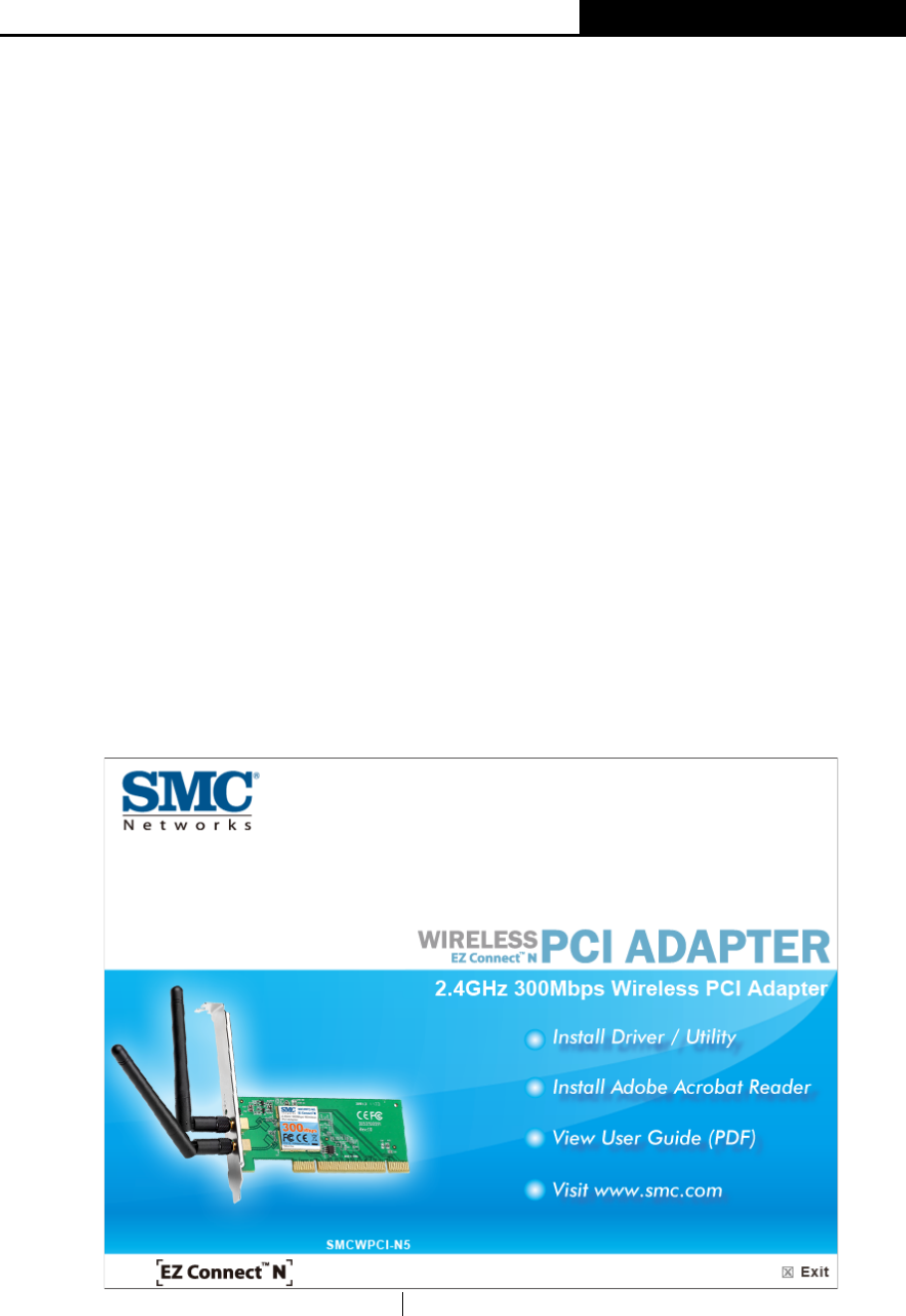
1. Insert the Resource CD into your CD-ROM drive, and open the folder named SMCWPCI-N5.
Double-click Setup.exe to start the installation, and then the following screen for preparing
setup will appear.
Figure 2-1
SMCWPCI-N5 300M Wireless N PCI Adapter
4
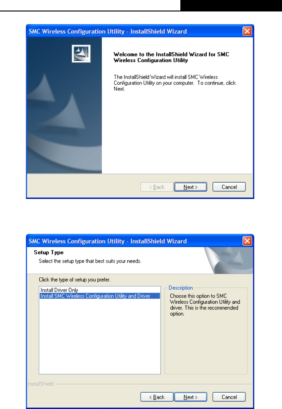
2. The InstallShield Wizard window will appear. Click Next to continue.
Figure 2-2
3. Choose a setup type. It is recommended to select Install SMC Wireless Configuration
Utility and Driver. Selecting Install Driver Only will only install driver. Click Next to
continue.
Figure 2-3
SMCWPCI-N5 300M Wireless N PCI Adapter
5
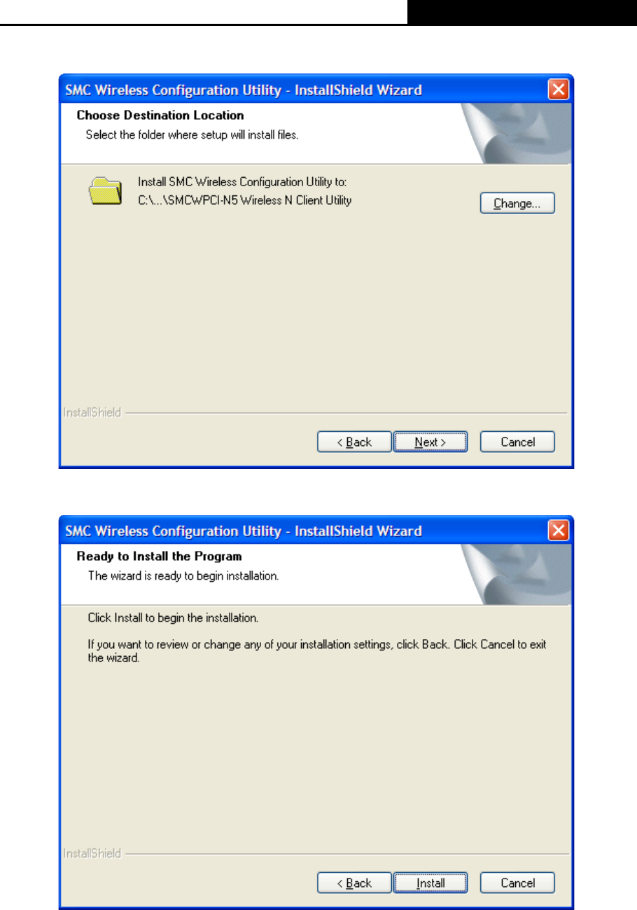
4. Click Change to specify the destination location for the software or you can leave it default.
Click Next in the screen below to continue.
Figure 2-4
5. Click Install to continue the setup.
Figure 2-5
SMCWPCI-N5 300M Wireless N PCI Adapter
6
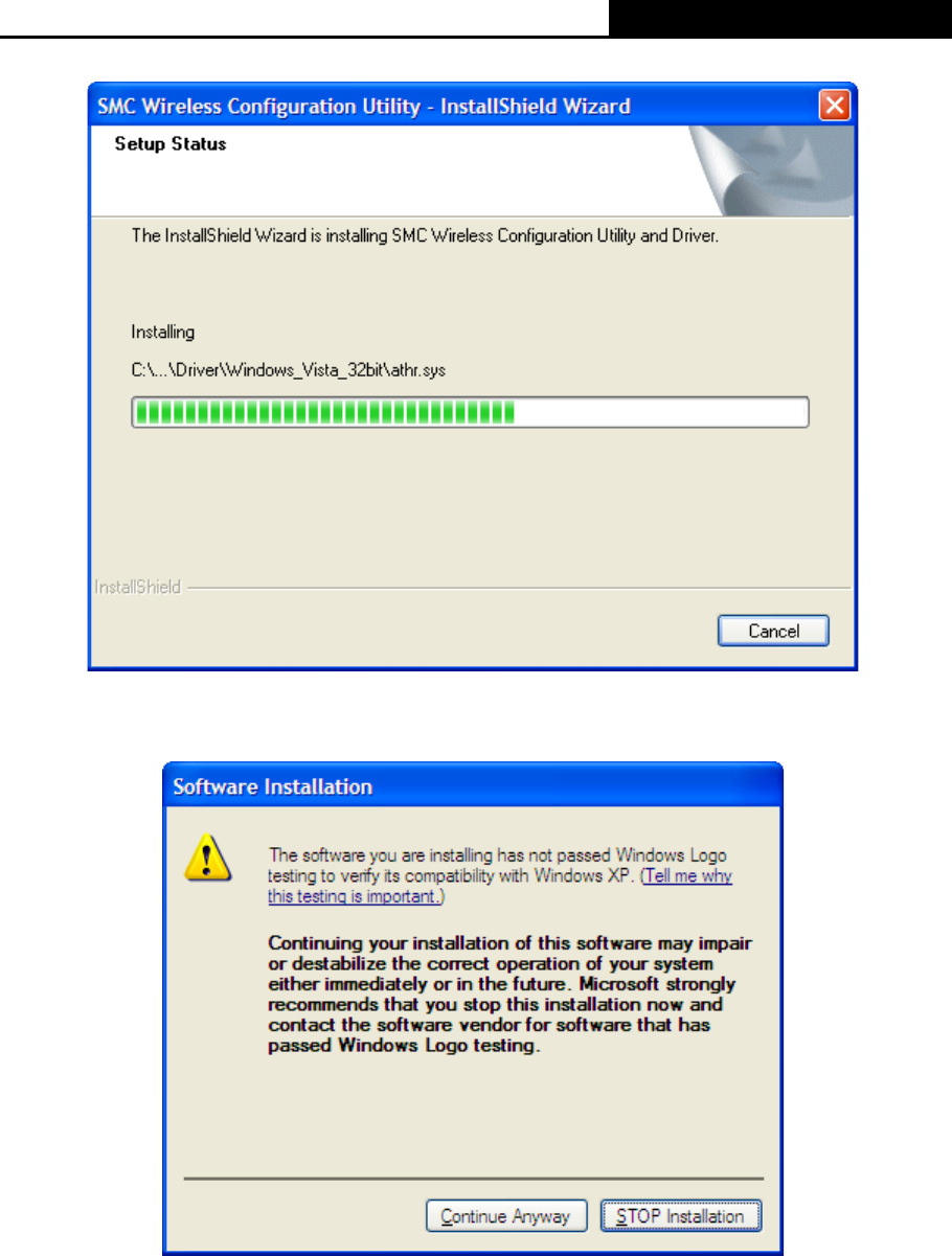
6. The utility and drivers will install. This may take 1~2 minutes.
Figure 2-6
7. If Windows XP warns about Windows Logo testing, click Continue Anyway to continue the
installation.
Figure 2-7
SMCWPCI-N5 300M Wireless N PCI Adapter
7
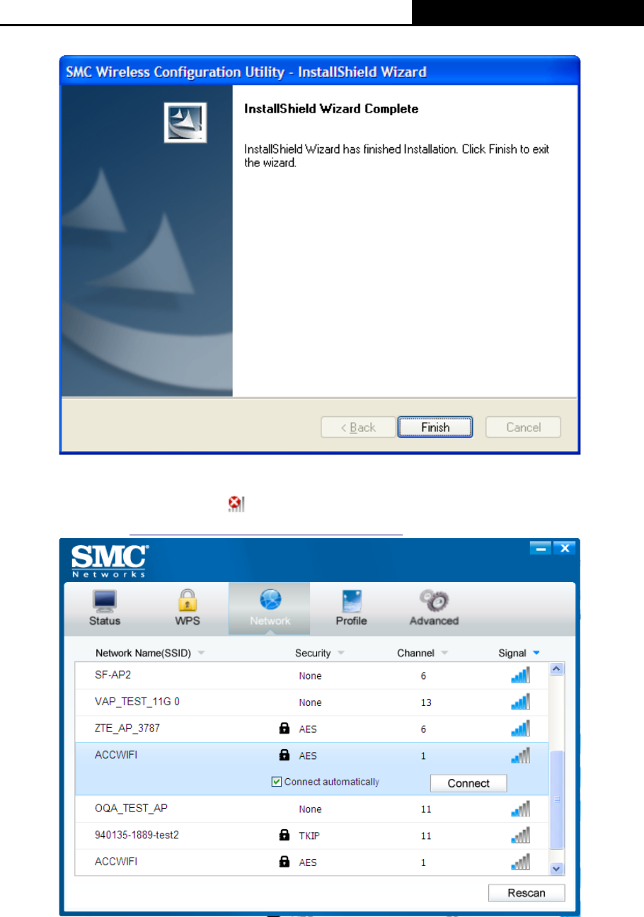
8. After all the steps above, you will see the screen below. Click Finish to complete the setup.
Figure 2-8
9. After installation, the utility configuration page will automatically pop up as shown in the
following figure and the icon will appear in your system tray. To connect to a network,
please refer to Chapter 3 Connect to a Wireless Network.
Figure 2-9
SMCWPCI-N5 300M Wireless N PCI Adapter
8
Chapter 3 Connect to a Wireless Network
With both the hardware and software successfully installed into your computer, you can quickly
connect to a wireless network using one of the following methods.
¾ Method One:
To connect using SMC Wireless Configuration Utility
SMCWPCI-N5 uses the SMC Wireless Configuration Utility as the management software. The
utility provides you an easy interface to connect to a network and to change any settings related to
the wireless adapter.
¾ Method Two:
To connect using QSS
By this method, you can connect to your network quickly on the condition that your router or
access point supports QSS or WPS as is called by some other brands.
¾ Method Three:
To connect using Windows built-in wireless utility
Windows users may use the built-in wireless utility to connect to a wireless network. For specific
operations, please go to To connect using Windows built-in wireless utility.
3.1 To connect using SMC Wireless Configuration Utility
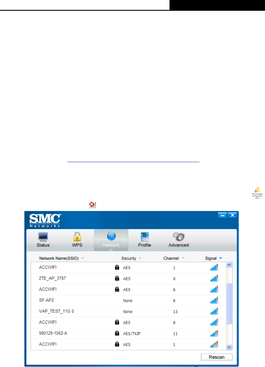
1. After installation, the utility configuration page will automatically pop up on the screen. If the
utility page does not pop up, you can also launch the utility by double-clicking on the
icon on your desktop or the icon in your system tray.
Figure 3-1
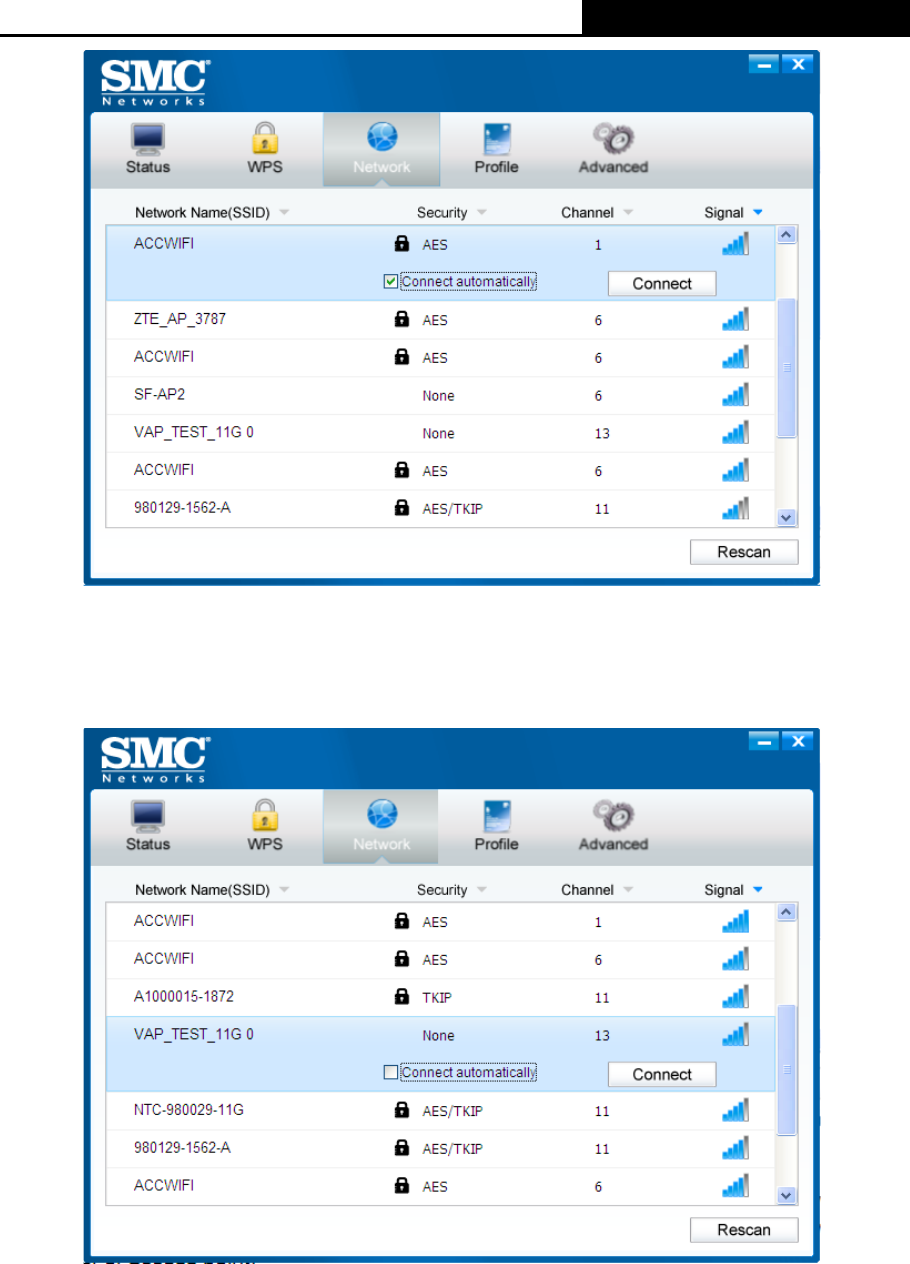
2. The Network page will display all wireless networks that are available in your area. To
connect to a network, simply highlight the wireless network name and click Connect.
SSID (Service Set Identifier) is the name of the wireless network. The adapter will
automatically connect to your target network next time if you tick Connect automatically.
SMCWPCI-N5 300M Wireless N PCI Adapter
9
Figure 3-2
3. If word None appears behind the SSID, this means the network to be connected is not
security-enabled and you can connect to the network without entering a key. To prevent
outside intrusion and safeguard your network, it is strongly recommended to set a password
to your router or access point.
Figure 3-3
If there is a “lock” icon behind the SSID, this means the wireless network is secure and the
corresponding security type will display. You must know the encryption key/security settings
to connect.
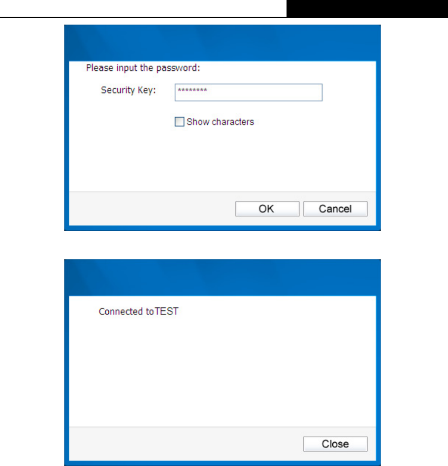
Input the password which can be found on the configuration page of your router or access
point, then click OK to continue. Or push the QSS/WPS button on your router if your router
features the QSS/WPS function to quickly build a connection without having to enter a key.
SMCWPCI-N5 300M Wireless N PCI Adapter
10
Figure 3-4
4. You have now successfully connected to your network. Click Close to enjoy the Internet.
Figure 3-5
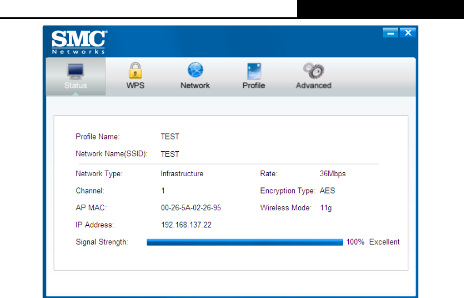
5. To view more information about the network currently connected, click Status in the tools
section and the page will display information such as the network type, link quality and
wireless mode.
SMCWPCI-N5 300M Wireless N PCI Adapter
11
Figure 3-6
3.2 To connect using WPS
WPS (Wi-Fi Protected Setup) function allows you to add a new wireless device to an existing
network quickly.
If the wireless router supports Wi-Fi Protected Setup (WPS) or QSS, you can establish a wireless
connection between wireless card and router using either Push Button Configuration (PBC)
method or PIN method. Three WPS connection methods are listed in the following parts while the
third method is only supported in Windows XP and Windows Vista.
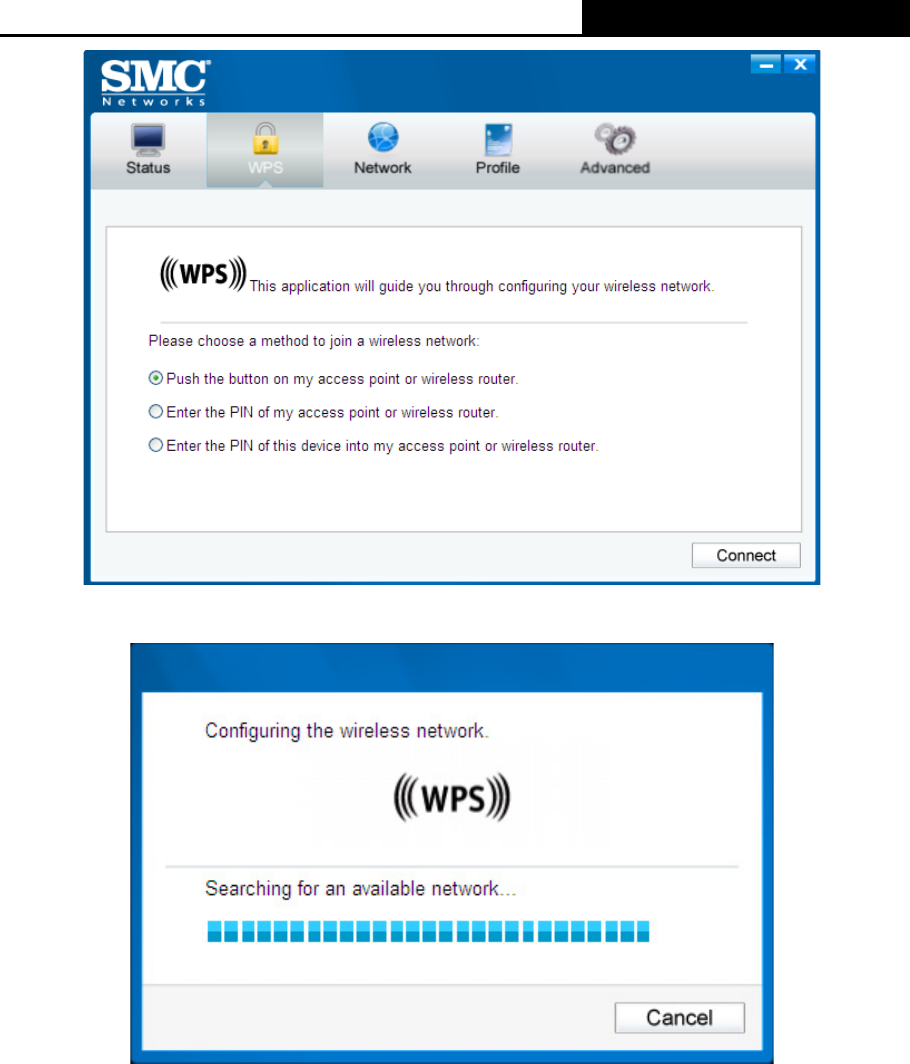
3.2.1 PBC (Push Button Configuration) method
1. Press the WPS/QSS button on the back panel of the router.
2. Open SMC WIRELESS CONFIGURATION UTILITY and click WPS tab. Select Push the
button on my access point or wireless router and then click Connect.
SMCWPCI-N5 300M Wireless N PCI Adapter
12
Figure 3-7
3. The adapter will be connecting to the target network.
Figure 3-8
SMCWPCI-N5 300M Wireless N PCI Adapter
13
4. When the following window appears, you have successfully connected to the network.
Figure 3-9
3.2.2 PIN method
There are two ways to configure the QSS by PIN method:
1) Enter the PIN from your AP device.
2) Enter a PIN into your AP device.
Following are detailed configuration procedures of each way.
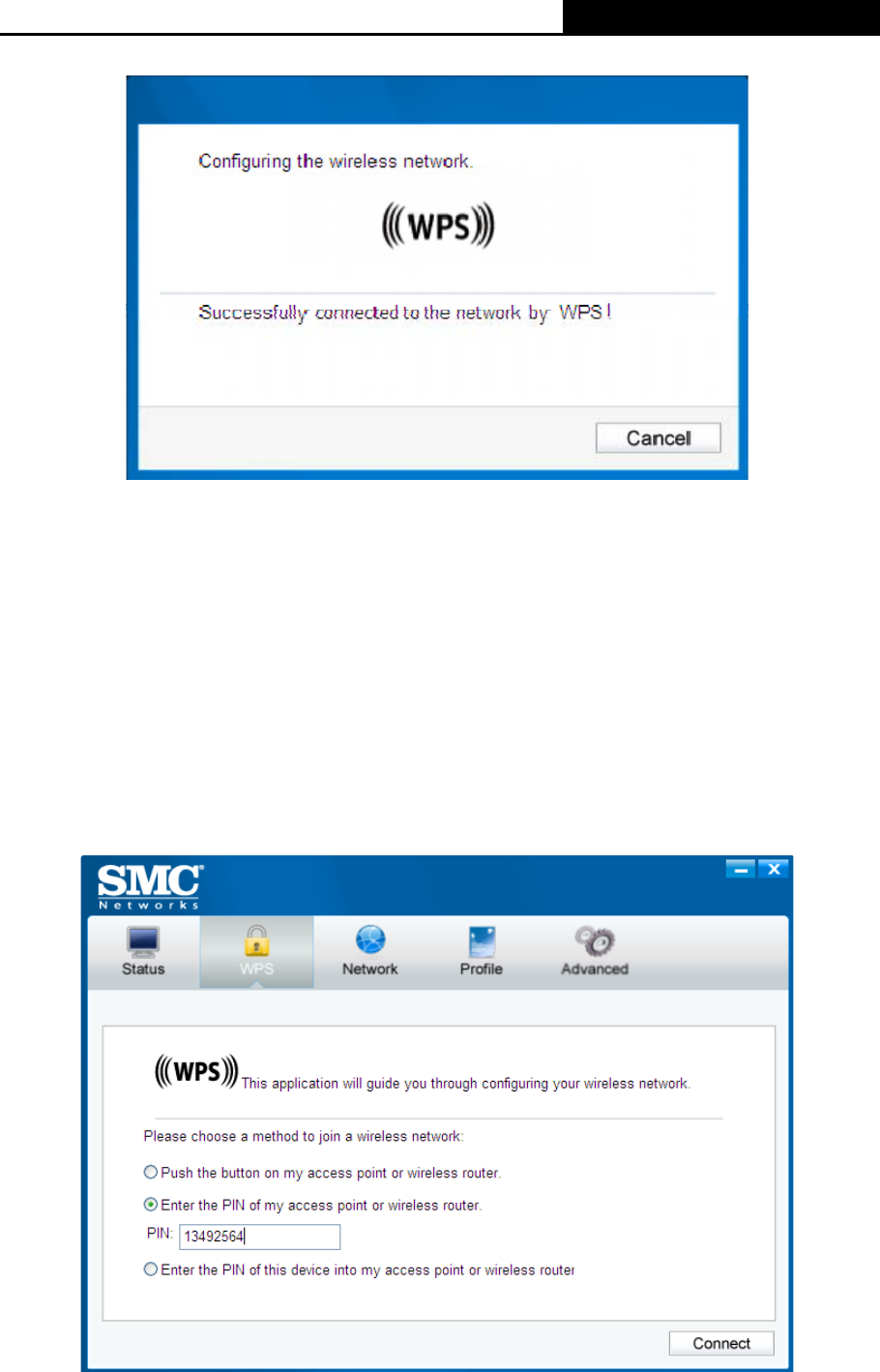
3.2.2.1. Enter the PIN from your AP device
1. Open SMC WIRELESS CONFIGURATION UTILITY and click WPS tab. Select Enter the
PIN of my access point or wireless router. In the empty field beside PIN, enter the PIN
labeled on the bottom of the router (here takes 13492564 for example). If you have generated
a new PIN code for your router, please enter the new one instead. Click Connect to continue.
Figure 3-10
SMCWPCI-N5 300M Wireless N PCI Adapter
14
2. The adapter will be connecting to the target network.
Figure 3-11
3. When Figure 3-9 appears, you have successfully connected to the network.
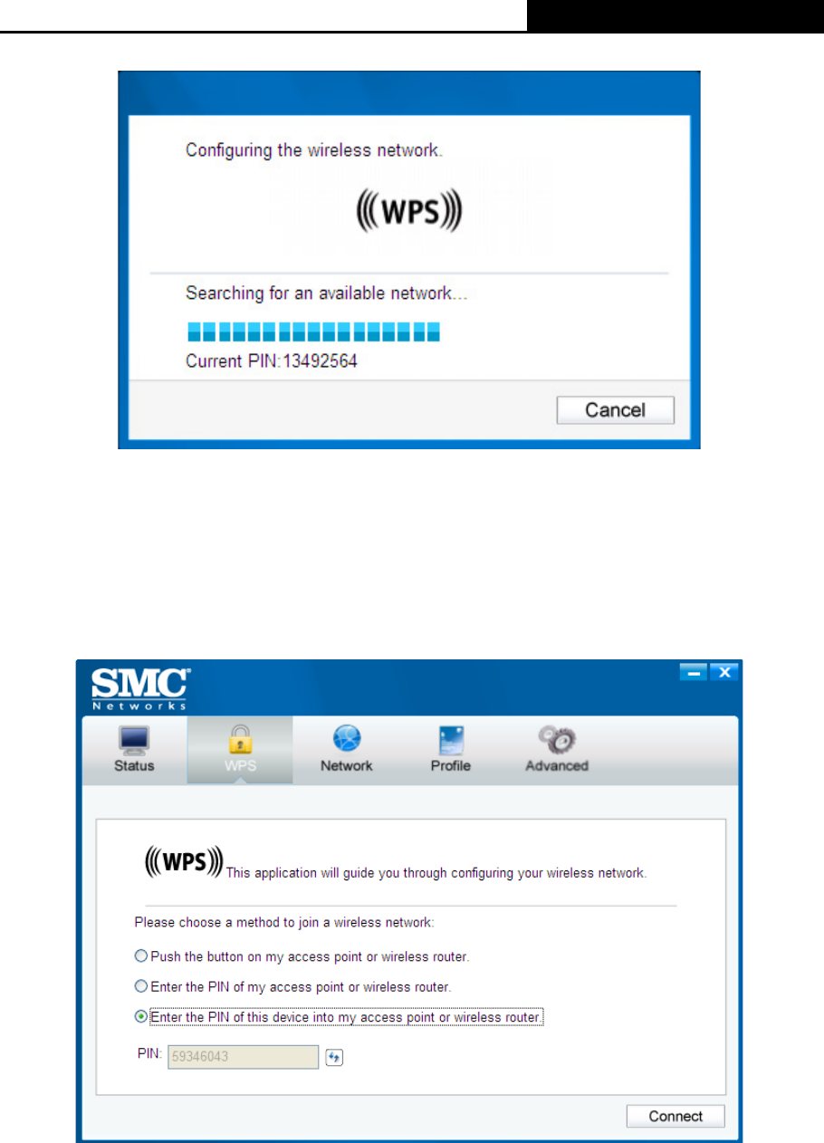
3.2.2.2. Enter a PIN into your AP device
This method is only available in Windows XP and Windows Vista.
1. Open SMC WIRELESS CONFIGURATION UTILITY and click WPS tab. Select Enter the
PIN of this device into my access point or wireless router. In the field beside PIN, you will
see the PIN value of the adapter which is randomly generated. Click Connect to continue.
Figure 3-12
2. Open your router’s Web-based Utility and click WPS/QSS link on the left of the main menu.
Then click Add device and the following figure will appear. Enter the PIN value of the adapter
in the empty field beside PIN and then click Connect.
3. When Connect successfully appears on the screen, the WPS configuration is complete. Or
you can view the adapter’s utility page to see whether the connection has been successful as
shown in Figure 3-15.
SMCWPCI-N5 300M Wireless N PCI Adapter
15
Figure 3-13
3.3 To connect using Windows built-in wireless utility
The steps are similar for all Microsoft Windows systems. The interface for Windows XP is
described in this user guide.
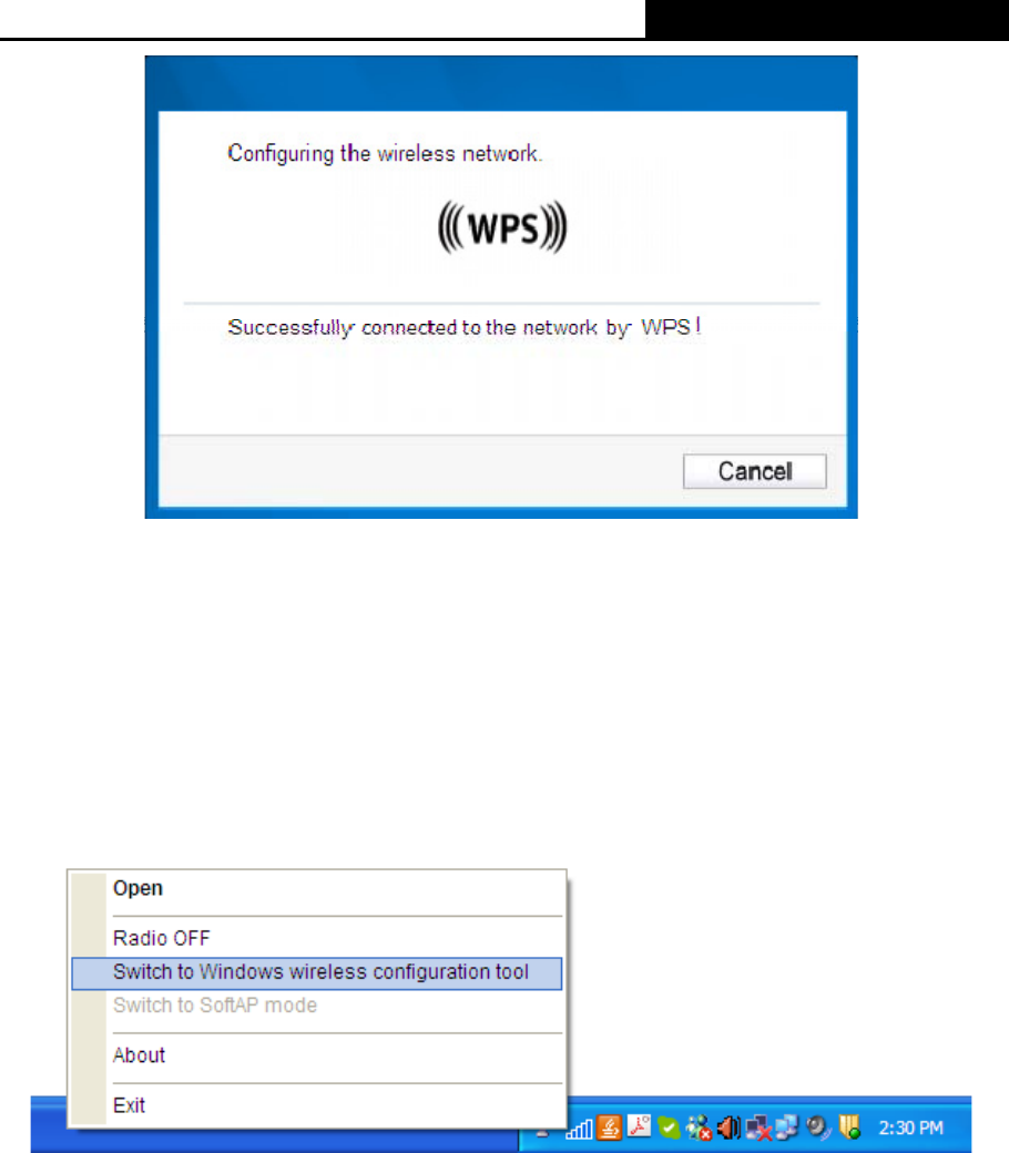
3.3.1 In Windows XP
Windows XP users may use the built-in wireless utility. Follow the steps below.
1. Right-click on the utility icon in your system tray (lower-right corner). Select Switch to SMC
Wireless N Client Utility.
Figure 3-14
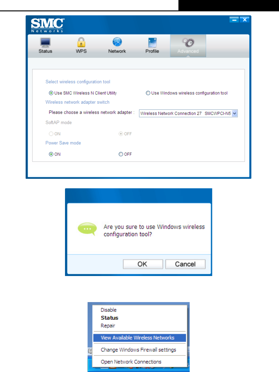
Or double-click the utility icon to load the utility configuration page. Click Advanced in the
tools section and then select Use Windows wireless configuration tool in the figure shown
below. Click OK when Figure 3-25 appears to continue.
SMCWPCI-N5 300M Wireless N PCI Adapter
16
Figure 3-15
Figure 3-16
2. Right-click on the wireless computer icon in your system tray (lower-right corner). Select
View Available Wireless Networks.
Figure 3-17
SMCWPCI-N5 300M Wireless N PCI Adapter
17
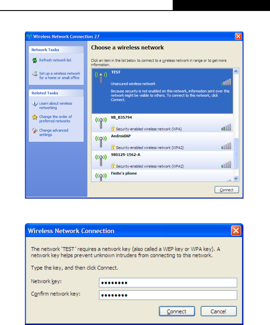
3. The utility will display any available wireless networks in your area. Click on a network
(displayed using the SSID) and click the Connect button.
Figure 3-18
4. If the network is security-enabled, you will be prompted to enter the key as shown below. If
not, you will connect to the network directly without entering a key.
Figure 3-19
SMCWPCI-N5 300M Wireless N PCI Adapter
18
Chapter 4 Management
This section will show you how to configure your SMCWPCI-N5 adapter using the SMC Wireless
Configuration Utility.
The SMCWPCI-N5 adapter uses the SMC Wireless Configuration Utility as the management
software. The utility provides users with an easy interface to change any settings related to the
adapter. Double-clicking on the icon on your desktop will start the utility.
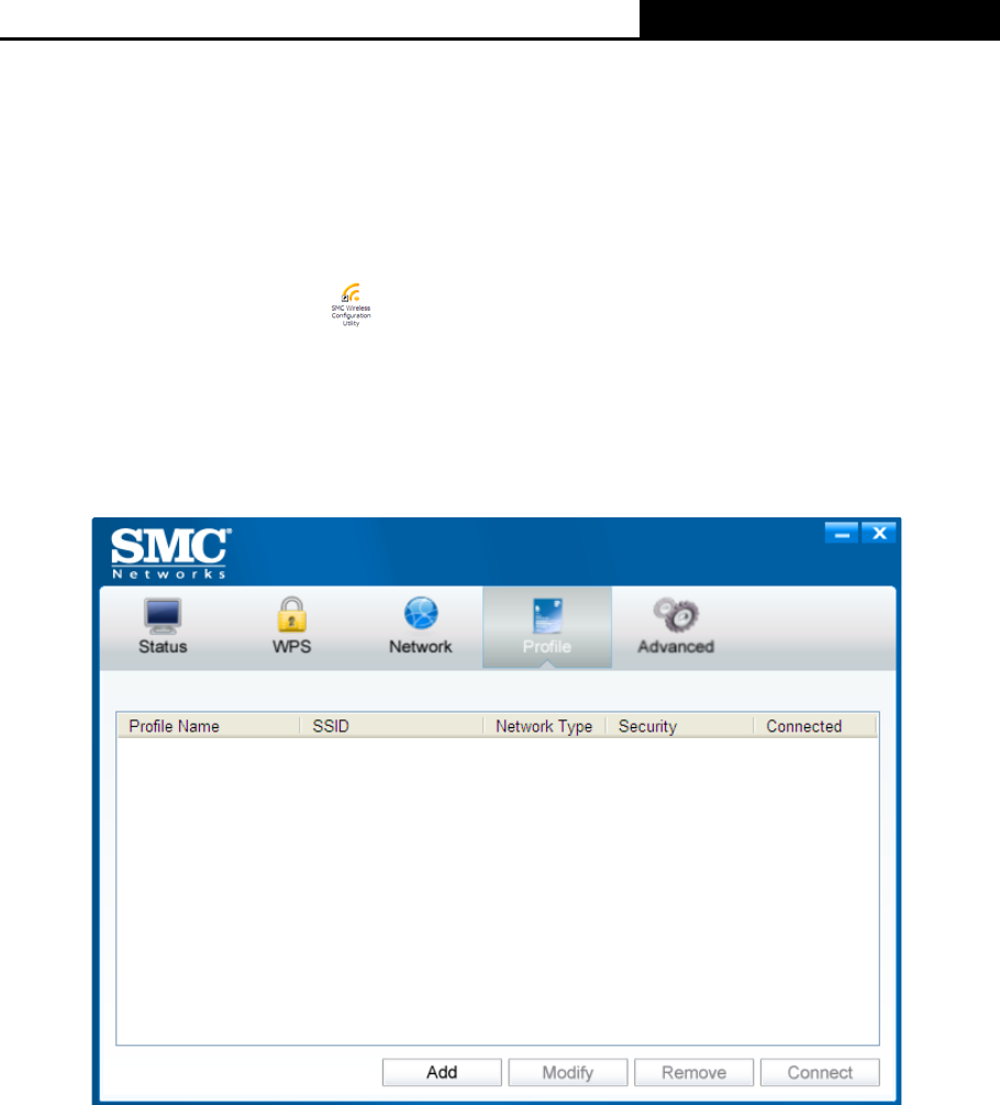
4.1 Profile
Your wireless networks may vary in different places like home, office or coffee shop. With Profile
management, you can easily save and manage various networks to be connected, saving you the
trouble of having to repeat the same configurations. Click Profile in the tools section, the following
page will appear.
Figure 4-1
4.1.1 Add a profile
To add a profile, click the Add button on the bottom of the screen. Then the configuration window
will appear.
SMCWPCI-N5 300M Wireless N PCI Adapter
19
Figure 4-2
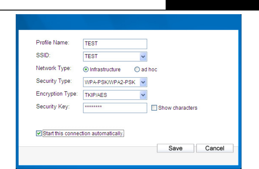
The following items can be found on the screen.
¾ Profile Name: Enter a name for your profile (e.g. Home, Office, CoffeeShop). The same
name is not allowed. Please also note that no space is allowed between words.
¾ SSID: Select the target network from the drop-down list.
¾ Network Type: Select the network type. If you are connecting to a wireless router or access
point, select Infrastructure. If you are connecting to another wireless client such as an
adapter, select ad-hoc.
¾ Security Type: Select the security type from the list. Three options are available:
WPA-PSK/WPA2-PSK, WEP and None. The security type should be the same as on your
router or access point, otherwise, you will not be able to build a successful connection.
WPA-PSK/WPA2-PSK uses a passphrase or key to authenticate your wireless connection.
The key must be the exact same key entered on your wireless router or access point. None
stands for no security. It is recommended to enable WPA-PSK/WPA2-PSK on your wireless
router or access point before configuring your wireless adapter.
¾ Encryption Type: From the drop-down menu, select the encryption type that is the same as
on your router or access point.
¾ Security Key: Enter the passphrase exactly as it is on your wireless router or access point.
Click the Show characters box to see the passphrase. Unchecking it will hide it.
¾ Start this connection automatically: check this box to automatically connect to this network
next time.
¾ Save: Click Save to save your settings.
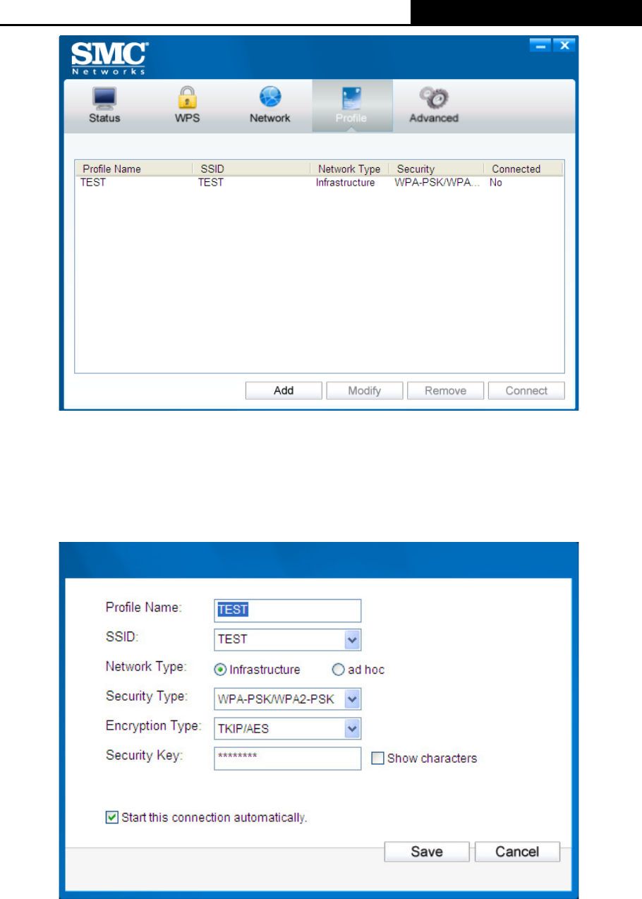
Complete the above settings, the Profile page should look like the following figure. To connect to a
desired network, just highlight the network you would like to connect to and click the Connect
button on the bottom of the window.
SMCWPCI-N5 300M Wireless N PCI Adapter
20
Figure 4-3
4.1.2 Modify a profile
You may edit an existing profile by clicking the Modify button from the Profile page. For instance,
you may like to change the profile name from test to test1 or you may want to specify another
SSID for profile Home. After all the changes, click Save to make the changes take effect.
Figure 4-4
SMCWPCI-N5 300M Wireless N PCI Adapter
21
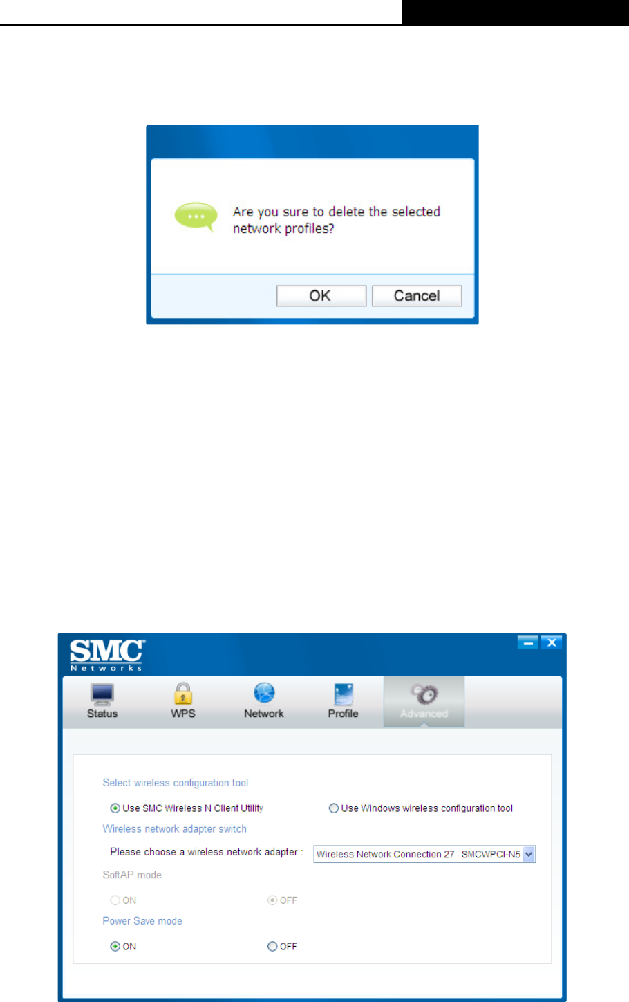
4.1.3 Delete a profile
To delete an existing profile, highlight the profile name and click Remove on the bottom of the
screen or press the Delete button on your keyboard. When the following figure appears, click OK
to continue.
Figure 4-5
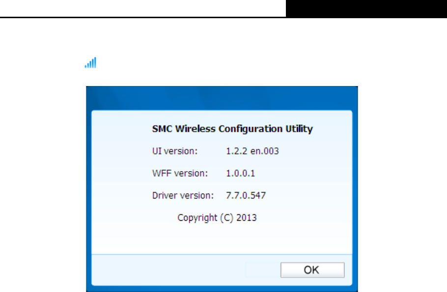
4.2 Advanced
The following configurations can be made on the Advanced page:
1) To select wireless configuration tool.
Here you can decide which tool to use, either the SMC WIRELESS CONFIGURATION
UTILITY or the Windows wireless configuration tool. This option is available only in Windows
XP.
2) To switch to another wireless network adapter.
Here you can switch to another adapter installed in your computer. The adapters successfully
installed in your computer will be listed in the drop-down menu if the adapters are supported
by this utility.
3) To switch to SoftAP mode.
Once enabled, the adapter will be able to work as an AP. This option is only available in
Windows 7.
4) To change the power save mode. The default option is ON.
Figure 4-6
SMCWPCI-N5 300M Wireless N PCI Adapter
22
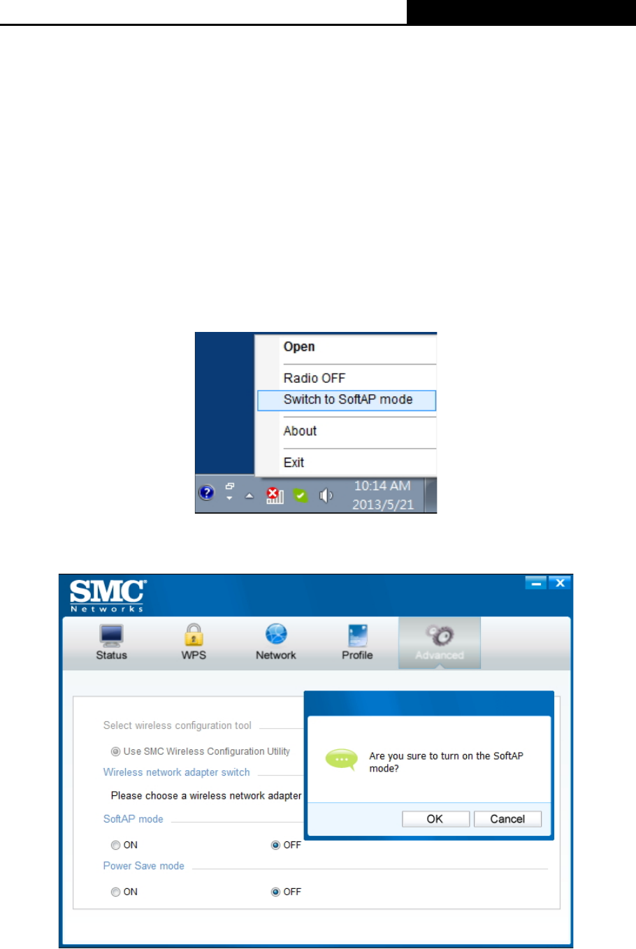
4.3 About
The About screen gives you information about the Driver and Utility versions of the adapter.
Right-click on the icon in your system tray and select About from the list.
Figure 4-7
SMCWPCI-N5 300M Wireless N PCI Adapter
23
Chapter 5 AP Mode (For Windows 7 only)
In Soft AP mode, the adapter will work as an AP. This function is available only in Windows 7.
Suppose that only one computer in your house can access the Internet for various reasons like
only one WLAN port is available on your wired broadband router, however, other wireless-capable
devices also want to share the Internet. Then the adapter can be configured as an AP under the
Soft AP mode, saving you the trouble of having to get a separate access point or a router.
With this feature, a computer can use a single physical wireless adapter to connect as a client to a
hardware access point while at the same time acting as a software AP allowing other
wireless-capable devices to connect to it.
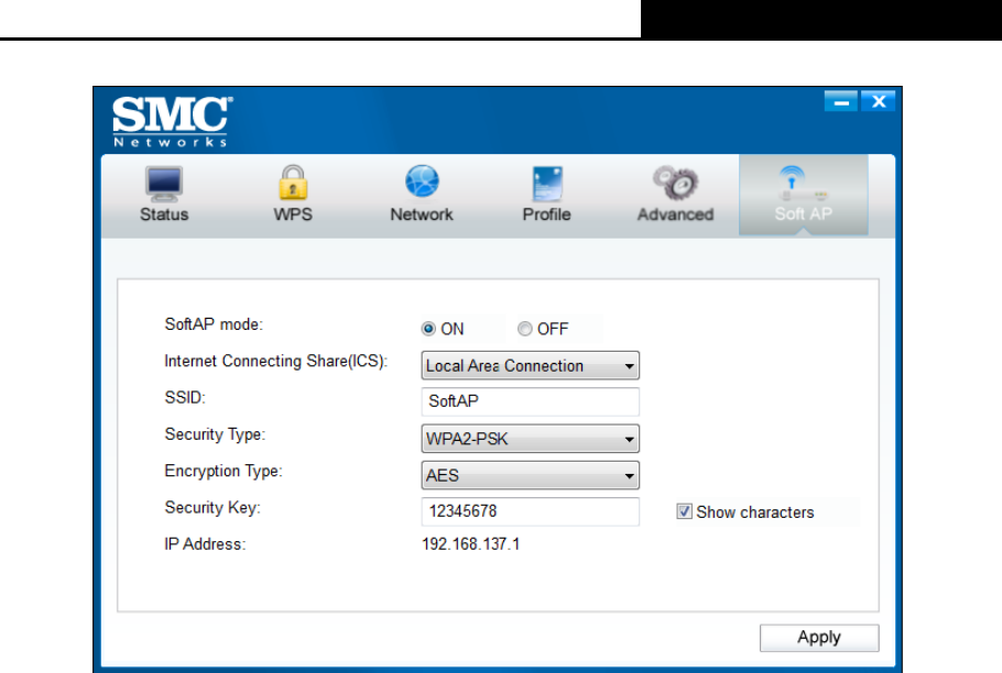
5.1 SoftAP mode
To switch to this mode, right-click on the utility icon in your system tray and select Switch to
SoftAP mode.
Figure 5-1
Or from the Advanced page of the utility, tick ON under the SoftAP mode as shown in the
following figure. Click OK when prompted to confirm the setting.
Figure 5-2
SMCWPCI-N5 300M Wireless N PCI Adapter
24
The Soft AP icon should then appear beside Advanced icon in the utility.
Figure 5-3
¾ SoftAP mode: Select to enable or disable the function.
¾ Internet Connecting Share(ICS): Specify a connection through which devices connected to
your AP can access the Internet.
¾ SSID: Enter the name for your soft AP (for example, Jone) so that others can know which AP
is yours when trying to connect to it.
¾ Security Type: The security type here is set to be WPA2-PSK which is based on 802.11i and
uses Advanced Encryption Standard instead of TKIP. It was designed to improve the security
features of WEP. WPA2-PSK uses a passphrase or key to authenticate your wireless
connection. You needn’t make any configuration here.
¾ Encryption Type: The encryption type here is set to be AES.
¾ Security Key: Enter the Key in the field to make your AP security enabled (for example
123456789). Only by entering the corresponding key can other computers establish a
successful connection with your AP.
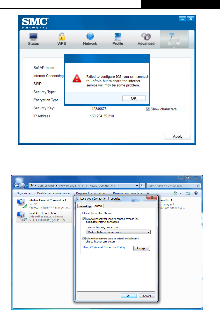
¾ IP Address: Here displays the IP address of the SoftAP.
Note: When switch to SoftAP mode, If a warning massage pops up as shown in the following
figure . Please follow the steps to activate SoftAP mode.
SMCWPCI-N5 300M Wireless N PCI Adapter
25
Figure 5-4
1) Go to Control Panel and select Network and Connections, double click the Local Area
Connection. From the Sharing tab, choose Microsoft Virtual WiFi Miniport Adapter Wireless
Network Connection.
Figure 5-5
2) The IP Address will change to 192.168.137.1. Now the SoftAP mode is activated
successfully..
SMCWPCI-N5 300M Wireless N PCI Adapter
26
Chapter 6 Uninstall Software
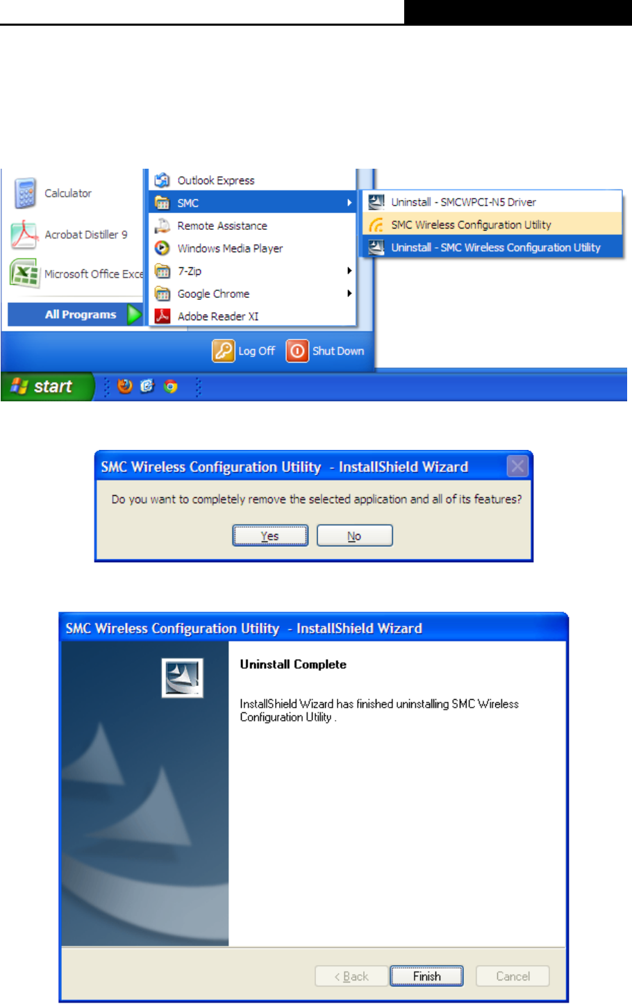
6.1 Uninstall the utility software from your PC
1. On the Windows taskbar, click the Start button, click All programs
Æ
S
MC
, and then
click Uninstall-SMC Wireless Configuration Utility.
Figure 6-1 Uninstall Utility
2. Follow the Install Shield Wizard to uninstall the utility software from your PC.
Figure 6-2
3. Click Finish when the figure below appears.
Figure 6-3
SMCWPCI-N5 300M Wireless N PCI Adapter
27
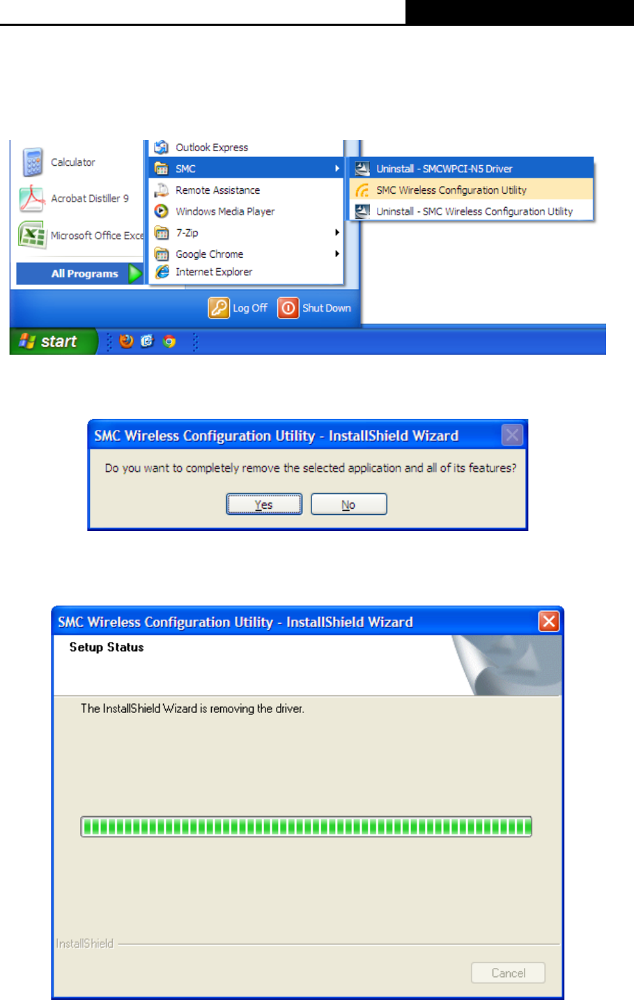
6.2 Uninstall the driver software from your PC
1. On the Windows taskbar, click the Start button, click All programs
ÆSMC
, and then
click Uninstall-SMCWPCI-N5 Driver.
Figure 6-5 Uninstall Driver
2. Click Yes to start uninstalling the driver software from your PC.
Figure 6-6
3. It may take a few minutes to undergo the whole un-installation process.
Figure 6-7
SMCWPCI-N5 300M Wireless N PCI Adapter
28
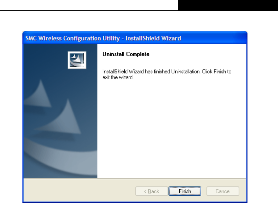
4. Click Finish when the figure below appears.
Figure 6-8

SMCWPCI-N5 300M Wireless N PCI Adapter
29
Appendix A: Specifications
Normal
Interface PCI 2.0, 32 bit PCI connector, Low-profile bracket included
Standards IEEE 802.11b/g, IEEE 802.11n, IEEE 802.11i, IEEE 802.11e
Operating System Windows XP, Windows Vista, Windows 7
Throughput 300 Mbps (maximum)
Radio Data Rate
11n:
270/243/216/162/108/81/54/27 Mbps
135/121.5/108/81/54/40.5/27/13.5 Mbps
130/117/104/78/52/39/26/13 Mbps
65/58.5/52/39/26/19.5/13/6.5 Mbps (dynamic)
11g: 108/54/48/36/24/18/12/9/6 Mbps (dynamic)
11b: 11/5.5/2/1 Mbps (dynamic)
Modulation
11b:CCK,QPSK,BPSK
11g:OFDM
11n: QPSK, BPSK, 16-QAM, 64-QAM
Media Access Protocol CSMA/CA with ACK
Operating Channel 11 channels (US, Canada), 2412~2462 MHz
13 channels (ETSI), 2412~2472 MHz
Data Security WPA/WPA2, WEP, TKIP/AES
RF Power 16 dBm (maximum)
Receive Sensitivity 270M: -68 dBm@10% PER
130M: -68 dBm@10% PER
108M: -68 dBm@10% PER
54M: -68 dBm@10% PER
11M: -85 dBm@8% PER
6M: -88 dBm@10% PER
1M: -90 dBm@8% PER
Antenna Gain 2 dBi
Antenna Type Two detachable omnidirectional antennas
Dimensions Unit:
4.8 x 4.8 x 0.78 in (122 x 121 x 19 mm)
Package:
7.9 x 5.7 x 1.4 in (202 x 145 x 35 mm)
Weight Unit: 47 g
Antenna: 9 g per piece
Frequency* 2.4 ~ 2.4835GHz
Spread Spectrum Direct Sequence Spread Spectrum (DSSS)
Safety & Emissions FCC, CE, IC, Compliant with RoHS
Environmental and Physical
Working Temperature 0°C ~40°C (32°F ~104°F)
Working Humidity 10% ~ 90% RH, Non-condensing
Storage Temperature -40°C ~70°C (-40°F ~158°F)
Storage Humidity 10% ~ 90% RH, Non-condensing

SMCWPCI-N5 300M Wireless N PCI Adapter
30
* Only 2.412GHz~2.462GHz is allowed to be used in USA, which means only channel 1~11 is
available for American users to choose.

SMCWPCI-N5 300M Wireless N PCI Adapter
31
Appendix B: Glossary
¾ 802.11b - The 802.11b standard specifies a wireless product networking at 11 Mbps using
direct-sequence spread-spectrum (DSSS) technology and operating in the unlicensed radio
spectrum at 2.4GHz, and WEP encryption for security. 802.11b networks are also referred to
as Wi-Fi networks.
¾ 802.11g - specification for wireless networking at 54 Mbps using direct-sequence
spread-spectrum (DSSS) technology, using OFDM modulation and operating in the
unlicensed radio spectrum at 2.4GHz, and backward compatibility with IEEE 802.11b devices,
and WEP encryption for security.
¾ 802.11n - 802.11n builds upon previous 802.11 standards by adding MIMO (multiple-input
multiple-output). MIMO uses multiple transmitter and receiver antennas to allow for increased
data throughput via spatial multiplexing and increased range by exploiting the spatial diversity,
perhaps through coding schemes like Alamouti coding. The Enhanced Wireless Consortium
(EWC) was formed to help accelerate the IEEE 802.11n development process and promote a
technology specification for interoperability of next-generation wireless local area networking
(WLAN) products.
¾ Ad hoc Network - An ad hoc network is a group of computers, each with a Wireless Adapter,
connected as an independent 802.11 wireless LAN. Ad hoc wireless computers operate on a
peer-to-peer basis, communicating directly with each other without the use of an access point.
Ad hoc mode is also referred to as an Independent Basic Service Set (IBSS) or as
peer-to-peer mode, and is useful at a departmental scale or SOHO operation.
¾ DSSS - (Direct-Sequence Spread Spectrum) - DSSS generates a redundant bit pattern for all
data transmitted. This bit pattern is called a chip (or chipping code). Even if one or more bits
in the chip are damaged during transmission, statistical techniques embedded in the receiver
can recover the original data without the need of retransmission. To an unintended receiver,
DSSS appears as low power wideband noise and is rejected (ignored) by most narrowband
receivers. However, to an intended receiver (i.e. another wireless LAN endpoint), the DSSS
signal is recognized as the only valid signal, and interference is inherently rejected (ignored).
¾ FHSS - (Frequency Hopping Spread Spectrum) - FHSS continuously changes (hops) the
carrier frequency of a conventional carrier several times per second according to a
pseudo-random set of channels. Because a fixed frequency is not used, and only the
transmitter and receiver know the hop patterns, interception of FHSS is extremely difficult.
¾ Infrastructure Network - An infrastructure network is a group of computers or other devices,
each with a Wireless Adapter, connected as an 802.11 wireless LAN. In infrastructure mode,
the wireless devices communicate with each other and to a wired network by first going
through an access point. An infrastructure wireless network connected to a wired network is
referred to as a Basic Service Set (BSS). A set of two or more BSS in a single network is
referred to as an Extended Service Set (ESS). Infrastructure mode is useful at a corporation
scale, or when it is necessary to connect the wired and wireless networks.
¾ Spread Spectrum - Spread Spectrum technology is a wideband radio frequency technique
developed by the military for use in reliable, secure, mission-critical communications systems.
It is designed to trade off bandwidth efficiency for reliability, integrity, and security. In other
words, more bandwidth is consumed than in the case of narrowband transmission, but the
trade off produces a signal that is, in effect, louder and thus easier to detect, provided that the
receiver knows the parameters of the spread-spectrum signal being broadcast. If a receiver is
not tuned to the right frequency, a spread-spectrum signal looks like background noise.

SMCWPCI-N5 300M Wireless N PCI Adapter
32
There are two main alternatives, Direct Sequence Spread Spectrum (DSSS) and Frequency
Hopping Spread Spectrum (FHSS).
¾ SSID - A Service Set Identification is a thirty-two character (maximum) alphanumeric key
identifying a wireless local area network. For the wireless devices in a network to
communicate with each other, all devices must be configured with the same SSID. This is
typically the configuration parameter for a wireless PC card. It corresponds to the ESSID in
the wireless Access Point and to the wireless network name. See also Wireless Network
Name and ESSID.
¾ WEP - (Wired Equivalent Privacy) - A data privacy mechanism based on a 64-bit or 128-bit or
152-bit shared key algorithm, as described in the IEEE 802.11 standard. To gain access to a
WEP network, you must know the key. The key is a string of characters that you create.
When using WEP, you must determine the level of encryption. The type of encryption
determines the key length. 128-bit encryption requires a longer key than 64-bit encryption.
Keys are defined by entering in a string in HEX (hexadecimal - using characters 0-9, A-F) or
ASCII (American Standard Code for Information Interchange – alphanumeric characters)
format. ASCII format is provided so you can enter a string that is easier to remember. The
ASCII string is converted to HEX for use over the network. Four keys can be defined so that
you can change keys easily.
¾ Wi-Fi - A trade name for the 802.11b wireless networking standard, given by the Wireless
Ethernet Compatibility Alliance (WECA, see http://www.wi-fi.net), an industry standards
group promoting interoperability among 802.11b devices.
¾ WLAN - (Wireless Local Area Network) - A group of computers and associated devices
communicate with each other wirelessly, which network serving users are limited in a local
area.
¾ WPA - (Wi-Fi Protected Access) - A wireless security protocol uses TKIP (Temporal Key
Integrity Protocol) encryption, which can be used in conjunction with a RADIUS server.
SMCWPCI-N5 300M Wireless N PCI Adapter
33
1910020621
REV1.0.0