Elbit Systems Land and C4I Tadiran MICOM-DS125W Licensed Non-Broadcast Station Transmitter - MICOM Z-Dash User Manual MICOM Z MME fp
Elbit Systems Land and C4I - Tadiran Ltd. Licensed Non-Broadcast Station Transmitter - MICOM Z-Dash MICOM Z MME fp
Contents
- 1. Operators Manual
- 2. Service Manual
- 3. User Manual 1
- 4. User Manual 2
Service Manual
MM-E 2072-09333-00
SERVICE MANUAL
FOR
MICOM-Z
HF-SSB TRANSCEIVERS
Revision A
JULY 2011
MM-E 2072-09333-00
i
WARNINGS, CAUTIONS AND NOTES
The following notations are used to place special emphasis on procedures, or to call attention to
precautionary measures.
WARNING
An operating procedure, practice and so forth, which if not followed
correctly, could result in personal injury, or loss of life.
CAUTION
An operating procedure, practice and so forth, which if not followed
correctly, could result in damage to, or destruction of equipment.
NOTE
An operating procedure, condition and so forth, to which special
attention should be paid.
GENERAL SAFETY PRECAUTIONS
Review Micom-Z Operator Manual with respect to safety precautions,
and installation and operation instructions. In particular, remember that
during transmission, high RF voltages may appear at internal points of
the printed circuit board, at the radio set and test station RF
connectors, the antenna cable, and on the dummy load or antenna
connected to the radio. Avoid touching the antenna and the RF
connectors of a radio set while it operates.
Operating and maintenance personnel must be familiar with the
applicable safety requirements before attempting to install, operate or
maintain the radio set.
WARNING
The backup battery is a Lithium battery that contains dangerous
chemicals. Handle and dispose of batteries according to the
prescribed safety regulations. In particular, observe the following
precautions:
1. Do not short-circuit the battery.
2. Do not damage battery case and do not tamper with battery in any
way.
3. Do not expose to heat or flame.
4. Do not dispose of used batteries by burning.
MM-E 2072-09333-00
ii
SAFETY SUMMARY
The following are general safety precautions that are not related to any specific procedures and
therefore do not appear elsewhere in this publication. These are recommended precautions that
personnel must understand and apply during various phases of operation and maintenance.
KEEP AWAY FROM LIVE CIRCUITS. Operating personnel must at all times observe all safety
regulations. Do not replace components or make adjustments inside the equipment with the high
voltage supply turned on. Under certain conditions, dangerous potentials may exist even when the
power control is in the OFF position, due to charges retained by capacitors. To avoid casualties,
always remove power and discharge and ground a circuit before touching it.
DO NOT SERVICE OR ADJUST ALONE. Under no circumstances should any person reach into the
equipment enclosure for the purpose of servicing or adjusting the equipment except in the presence of
someone who is capable of rendering aid.
RESUSCITATION. Personnel working with or near high voltages should be familiar with modern
methods of resuscitation.
USE SAFETY APPROVED EQUIPMENT. When cleaners and primers are being applied, approved
explosion-proof lights, blowers, and other equipment shall be used. Insure that firefighting equipment is
readily available and in working order.
GIVE CLEANERS SPECIAL CARE. Keep cleaners in special polyethylene bottles or in safety cans
and in minimum quantities. Discard soiled cleaning cloths into safety cans.
MM-E 2072-09333-00
iii
TABLE OF CONTENTS
Page
Chapter 1 INTRODUCTION
1-1. SCOPE .......................................................................................................................... 1-1
Chapter 2 THEORY OF OPERATION
Section I. GENERAL DESCRIPTION............................................................................................ 2-1
2-1. MICOM-Z DESCRIPTION ............................................................................................. 2-1
2-1.1 Micom-Z Dash-Mount Version ................................................................................... 2-1
2-1.2 Micom-Z Trunk-Mount Version .................................................................................. 2-9
2-1.3 Micom-Z Cooling Tray ............................................................................................. 2-15
2-2. OPTIONS AND ACCESSORIES................................................................................. 2-16
2-3. CONNECTOR DATA................................................................................................... 2-17
2-3.1 Micom-Z Connector Data......................................................................................... 2-17
2-3.2 Cooling Tray Connectors ......................................................................................... 2-19
Section II. CIRCUIT ANALYSIS ................................................................................................... 2-21
2-4. LORD MODULE .......................................................................................................... 2-21
2-4.1 Audio Subsystem..................................................................................................... 2-21
2-4.2 DSP Subsystem....................................................................................................... 2-21
2-4.3 ISB Option ............................................................................................................... 2-22
2-4.4 IF and RF Transmit Path ......................................................................................... 2-22
2-4.5 RF Front End ........................................................................................................... 2-25
2-4.6 Receive IF Path ....................................................................................................... 2-26
2-4.7 Synthesizer Subsystem ........................................................................................... 2-26
2-4.8 Main Microcomputer Subsystem ............................................................................. 2-29
2-4.9 Power Supply Subsystem........................................................................................ 2-30
2-4.10 LORD Module Test Point Data ................................................................................ 2-31
2-5. HI POWER MODULE.................................................................................................. 2-33
2-5.1 Power Amplifier (PA) ............................................................................................... 2-33
2-5.2 TX/RX Switch........................................................................................................... 2-33
2-5.3 Harmonic Filter Bank ............................................................................................... 2-33
2-5.4 Power Sensor .......................................................................................................... 2-34
2-5.5 ALC Circuits............................................................................................................. 2-34
2-5.6 Power Supply Subsystem........................................................................................ 2-37
2-6. CONTROL HEAD MODULE........................................................................................ 2-38
2-6.1 CONTROL HEAD Module for Dash-Mount Version................................................. 2-38
2-6.2 CONTROL HEAD Module for Trunk-Mount Version ................................................ 2-40
2-7. INTERCONNECTION MODULE ................................................................................. 2-42
2-8. FAN CONTROL MODULE .......................................................................................... 2-42
Chapter 3 MAINTENANCE
3-1. SCOPE .......................................................................................................................... 3-1
3-2. HANDLING PRECAUTIONS DURING MAINTENANCE .............................................. 3-1
3-3. CLEANING .................................................................................................................... 3-3
3-4. TESTING ....................................................................................................................... 3-3
3-4.1 Micom-Z Testing ........................................................................................................ 3-3
3-4.2 Module Testing and Alignment .................................................................................. 3-3
3-5. TROUBLESHOOTING .................................................................................................. 3-4
3-5.1 Overview of Troubleshooting Procedures.................................................................. 3-4
3-5.2 BIT Error Codes......................................................................................................... 3-4
3-5.3 Troubleshooting Procedure ....................................................................................... 3-6
3-5.4 Micom-Z Troubleshooting Charts .............................................................................. 3-9
3-5.5 Module Troubleshooting Procedures....................................................................... 3-16
3-6. MICOM-Z REPAIR PROCEDURES ............................................................................ 3-21
3-6.1 Micom-Z Dash-Mount Version Repair ..................................................................... 3-21
3-6.2 Repair of Micom-Z Trunk-Mount Version................................................................. 3-27
Appendix A SCHEMATIC CIRCUIT DIAGRAMS
Appendix B PARTS LISTS
Section I. MICOM-Z DASH-MOUNT VERSION ............................................................................B-1
Section II. MICOM-Z TRUNK-MOUNT VERSION........................................................................B-93
Section III. COOLING TRAY .......................................................................................................B-119
MM-E 2072-09333-00
iv
LIST OF ILLUSTRATIONS
Page
Figure 2-1. Micom-Z Dash-Mount Version Structure .................................................................................. 2-1
Figure 2-2. Micom-Z Dash-Mount Wiring Diagram ..................................................................................... 2-2
Figure 2-3. Micom-Z Dash-Mount Version, Functional Block Diagram...................................................... 2-5
Figure 2-4. Frequency Conversion Scheme................................................................................................ 2-7
Figure 2-5. Transmit Path Frequency Conversion Scheme ....................................................................... 2-8
Figure 2-6. Receive Path Frequency Conversion Scheme......................................................................... 2-8
Figure 2-7. Micom-Z Trunk-Mount Version, Structure of Body Assembly ................................................. 2-9
Figure 2-8. Micom-Z Trunk-Mount Version, Structure of Control Head ................................................... 2-10
Figure 2-9. Micom-Z Trunk-Mount Wiring Diagram ..................................................................................2-11
Figure 2-10. Micom-Z Trunk-Mount Version, Functional Block Diagram................................................... 2-13
Figure 2-11. Micom-Z Cooling Tray Structure ............................................................................................. 2-15
Figure 2-12. LORD Module, Block Diagram ................................................................................................ 2-23
Figure 2-13. Synthesizer 1, Functional Block Diagram ...............................................................................2-27
Figure 2-14. Synthesizer 2, Functional Block Diagram ...............................................................................2-28
Figure 2-15. LORD Module, Typical Test Point Signal Frequencies and Levels....................................... 2-31
Figure 2-16. LORD Test Points Map............................................................................................................ 2-32
Figure 2-17. HI POWER Module, Functional Block Diagram ..................................................................... 2-35
Figure 2-18. CONTROL HEAD Module for Dash-Mount Version, Functional Block Diagram ................. 2-38
Figure 2-19. CONTROL HEAD Module for Trunk-Mount Version, Functional Block Diagram.................2-40
Figure 2-20. INTERCONNECTION Module, Functional Block Diagram ................................................... 2-42
Figure 3-1. MICOM-Z Checkout Chart......................................................................................................... 3-9
Figure 3-2. MICOM-Z Troubleshooting Chart 1.........................................................................................3-11
Figure 3-3. MICOM-Z Troubleshooting Chart 2.........................................................................................3-12
Figure 3-4. MICOM-Z Troubleshooting Chart 3.........................................................................................3-13
Figure 3-5. MICOM-Z Troubleshooting Chart 4.........................................................................................3-14
Figure 3-6. MICOM-Z Troubleshooting Chart 5.........................................................................................3-15
Figure 3-7. MICOM-Z Troubleshooting Chart 6.........................................................................................3-15
Figure 3-8. MICOM-Z Troubleshooting Chart 7.........................................................................................3-16
Figure 3-9. Receiver Troubleshooting Flowchart ......................................................................................3-17
Figure 3-10. Transmitter Troubleshooting Flowchart ................................................................................. 3-19
Figure 3-11. Gaining Access to Modules .....................................................................................................3-21
Figure 3-12. Micom-Z with Front Panel Removed.......................................................................................3-21
Figure 3-13. Removal of LORD Assembly................................................................................................... 3-22
Figure 3-14. Removal of LORD Module....................................................................................................... 3-23
Figure 3-15. Removal of HI POWER Module.............................................................................................. 3-25
Figure 3-16. Replacement of CONTROL HEAD Module............................................................................ 3-26
Figure 3-17. Gaining Access to Micom-Z Trunk-Mount Version Modules ................................................. 3-27
Figure 3-18. Micom-Z Trunk-Mount Version with Front Cover Removed.................................................. 3-27
Figure 3-19. Replacement of CONTROL HEAD Module............................................................................ 3-29
Figure A-1. LORD Module, Schematic Circuit Diagram .............................................................................A-3
Figure A-2. HI POWER Module, Schematic Circuit Diagram ...................................................................A-39
Figure A-3. CONTROL HEAD Module, Schematic Circuit Diagram) .......................................................A-63
Figure A-4. INTERCONNECTION Module, Schematic Circuit Diagram..................................................A-69
Figure A-5. FAN CONTROL Module, Schematic Circuit Diagram ...........................................................A-65
MM-E 2072-09333-00
v
LIST OF ILLUSTRATIONS (Cont'd)
Page
Figure B-1. Micom-Z Assembly Dash Version ............................................................................................B-2
Figure B-2. LORD Assembly.........................................................................................................................B-4
Figure B-3. LORD Module, Identification of Components ........................................................................B-55
Figure B-4. HI POWER Module, Identification of Components ................................................................B-74
Figure B-5. Dash Front Panel, Control Head Assembly............................................................................B-79
Figure B-6. CONTROL HEAD Module (Dash Mount Version), Identification of Components................B-91
Figure B-7. Micom-Z Assembly, Trunk Version ........................................................................................B-94
Figure B-8. Trunk Front Panel, Control Head Assembly...........................................................................B-98
Figure B-9. CONTROL HEAD Module (Trunk Mount Version), Identification of Components.............B-113
Figure B-10. INTERCONNECTION Module, Identification of Components.............................................B-118
Figure B-11. Cooling Tray Assembly..........................................................................................................B-119
Figure B-12. FAN CONTROL Module, Identification of Components ......................................................B-120
Figure B-13. Fan Harness Assembly..........................................................................................................B-121
MM-E 2072-09333-00
vi
LIST OF TABLES
Page
Table 2-1. Available Options......................................................................................................................2-16
Table 2-2. Accessories .............................................................................................................................. 2-16
Table 2-3. Micom-Z Microphone Connector, Pin Functions ....................................................................2-17
Table 2-4. ACCESSORY Connector Pin Functions................................................................................. 2-17
Table 2-5. Micom-Z VDC IN Power Connector, Pin Functions ............................................................... 2-18
Table 2-6. Micom-Z 44-Pin/25-Pin Adapter Cable Wiring Diagram ........................................................2-19
Table 2-7. Cooling Tray 25-Pin ACCESSORY Connector Pin Functions............................................... 2-19
Table 2-8. Harmonic Filter Frequency Ranges and Controlling Relays.................................................. 2-34
Table 3-1. Tightening Torques for Screws ................................................................................................. 3-2
Table 3-2. BIT Error Codes ......................................................................................................................... 3-4
Table 3-3. Troubleshooting Procedure ....................................................................................................... 3-6
Table B-1. Micom-Z Assembly Dash Version, Parts List ...........................................................................B-1
Table B-2. LORD Assembly, Parts List .......................................................................................................B-4
Table B-3. LORD Module, Parts List ...........................................................................................................B-5
Table B-4. HI POWER Module, Parts List ................................................................................................B-59
Table B-5. Dash Front Panel, Control Head Assembly, Parts List ..........................................................B-79
Table B-6. CONTROL HEAD Module (Dash Mount Version), Parts List................................................B-80
Table B-7. Micom-Z Assembly, Trunk Version, Parts List .......................................................................B-93
Table B-8. LORD Assembly, Parts List .....................................................................................................B-96
Table B-9. HI POWER Module, Parts List ................................................................................................B-97
Table B-10. Trunk Front Panel, Control Head Assembly, Parts List..........................................................B-98
Table B-11. CONTROL HEAD Module (Trunk Mount Version), Parts List...............................................B-99
Table B-12. INTERCONNECTION Module, Parts List.............................................................................B-115
Table B-13. Cooling Tray Assembly, Parts List.........................................................................................B-119
Table B-14. FAN CONTROL Module, Parts List ......................................................................................B-120
Table B-15. Fan Harness Assembly, Parts List........................................................................................B-121

MM-E 2072-09333-00
1-1
Chapter 1
INTRODUCTION
1-1. SCOPE
This Service Manual provides the information needed to maintain Micom-Z HF-SSB radio sets in
accordance with manufacturer’s recommendations.
For a description of Micom-Z characteristics and capabilities, and for installation and operation
procedures, refer to the Micom-Z Operator Manual, Publication OM-E 2072-09689-00. The Micom-Z
Operator Manual also describes the cooling tray, available as an accessory for Micom-Z transceivers.
This Service Manual is organized as follows:
Chapter 1 Introduction: describes the scope and organization of the manual.
Chapter 2 Theory of Operation: presents the theory of operation of Micom-Z transceivers.
Chapter 3 Maintenance: provides test, troubleshooting and repair instructions for Micom-Z
transceivers and cooling tray.
Appendix A Schematic Circuit Diagrams: presents the schematic circuit diagrams of the
Micom-Z transceivers and the cooling tray.
Appendix B Parts Lists: lists and identifies the parts needed to maintain Micom-Z
transceivers and the cooling tray.
To facilitate equipment maintenance, the manufacturer offers two spare parts kits:
• Recommended spare boards kit for Micom-Z dash mount version, Mfg. Cat. No.
2072-09246-00
• Recommended spare boards kit for Micom-Z trunk mount version, Mfg. Cat. No.
2072-09247-00.
It is also possible to order 4-year extended warranties, in accordance with the options installed in each
transceiver:
• 4-year extended warranty for basic Micom-Z, Mfg. Cat. No. 2000-17777-90
• 4-year extended warranty for FRN8525 vocoder (FRN8529), Mfg. Cat. No. 2072-00235-00
• 4-year extended warranty for FRN8526 modem (FRN8530), Mfg. Cat. No. 2072-00236-00
• 4-year extended warranty for FRN8527 vocoder/modem (FRN8534), Mfg. Cat. No.
2072-00237-00.
Contact the manufacturer, or your local distributor, for any additional information you may need.
MM-E 2072-09333-00
1-2
Intentionally Left Blank
MM-E 2072-09333-00
2-1
Chapter 2
THEORY OF OPERATION
Section I. GENERAL DESCRIPTION
2-1. MICOM-Z DESCRIPTION
2-1.1 Micom-Z Dash-Mount Version
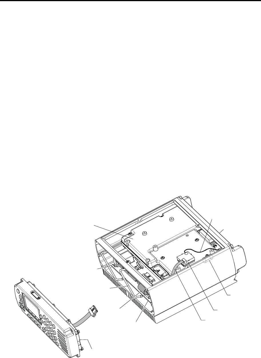
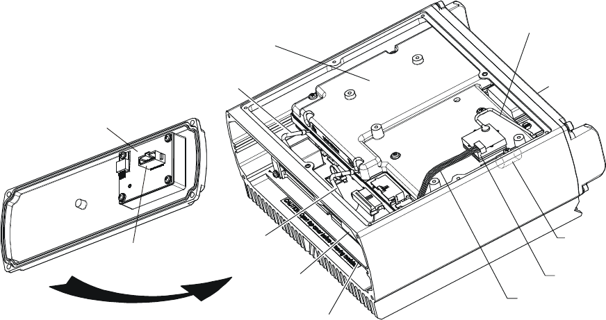
2-1.1.1 Structure
Figure 2-1 shows the structure of the Micom-Z dash-mount version. Micom-Z dash-mount version
consists of two main assemblies, attached by means of four screws:
• Body assembly. The body assembly includes two main modules, LORD and HI POWER,
interconnected by a few cables. The LORD module is actually an assembly protected by a shield
that also carries the optional GPS receiver and a backup battery for protecting the operational
parameters. The external connectors are located on the two modules, but are attached to the rear
panel, for physical support. The LORD and HI POWER modules can be accessed after opening
the top cover (not shown in Figure 2-1), and separating the front panel assembly (it is not
necessary to remove the rear panel, but connectors must be released from the panel before it is
possible to extract the modules).
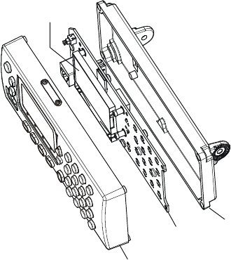
• Front panel assembly. This assembly includes the operator interface (controls, keypad, LCD), a
microphone connector, an internal speaker, and the CONTROL HEAD module. The front panel
assembly is connected to the LORD module by a single flat cable.
LORD
RX Coaxial
Cable
TX Coaxial
Cable
Flat Cable
LORD - HI POWER
Flat Cable
GPS - LORD
Body Assembly
Front Panel
Assembly
GPS Receiver
Rear Panel
Internal GPS
Antenna Cable
Backup
Battery
HI POWER
CONTROL HEAD
Module
Flat Cable
to LORD
Figure 2-1. Micom-Z Dash-Mount Version Structure
MM-E 2072-09333-00
2-2
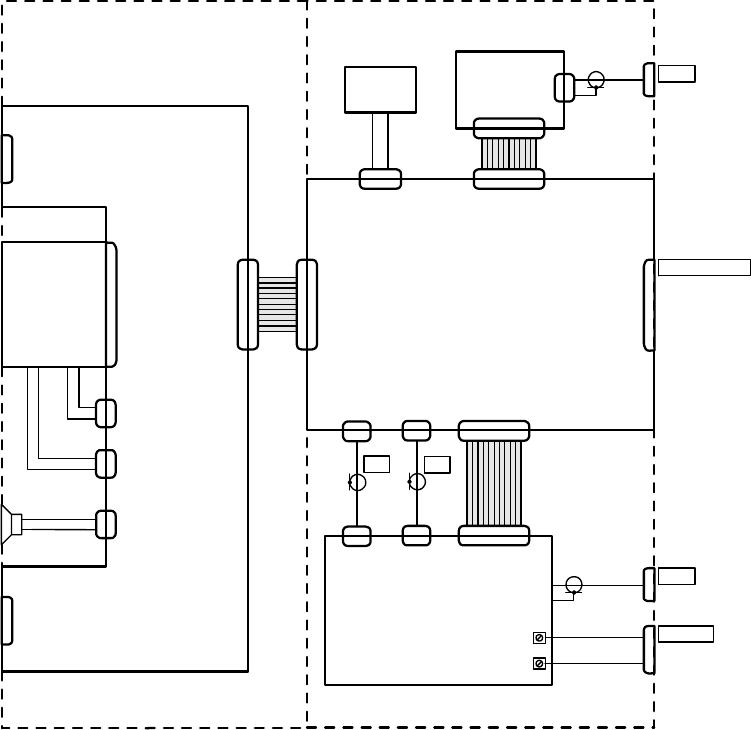
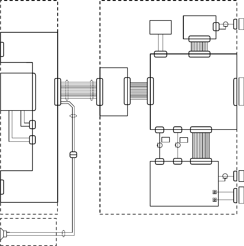
2-1.1.2 Wiring Diagram
Figure 2-2 shows the wiring diagram of the Micom-Z dash-mount version. Micom-Z dash-mount
version comprises the following main modules:
a. LORD module, includes the following main circuits:
(1) Audio signal processing circuits for the receive and transmit paths.
(2) Digital signal processor (DSP) and its auxiliary circuits.
(3) RF and IF modulation/demodulation and signal processing circuits for the receive and
transmit paths.
(4) Synthesizer and local oscillator circuits, and the Micom-Z frequency reference.
(5) Main microcomputer subsystem used to control the operation of the Micom-Z circuits. It
is part of the Micom-Z management subsystem, which also includes a microcomputer
subsystem located in the CONTROL HEAD module.
The module also includes the optional GPS receiver, and its interface.
LCD LORD
J4
P3 J6
GPS
GPS
Receiver
J8
Backup
Battery
J4
HI POWER
J3
J1
P3
RX
P2
J2
TX
P4
J5
ACCESSORY
ANT
VDC IN
E2
E1
J3
P2
P4
P1
P6
Body AssemblyFront Panel Assembly
Socket
for SD
Memory
Card
Microphone
Figure 2-2. Micom-Z Dash-Mount Wiring Diagram
b. HI POWER module, includes the following main circuits:
(1) Main power supply, provides the regulated voltages needed by the Micom-Z circuits, and
provides power for an external antenna tuner unit (ATU), connected to Micom-Z.
(2) Receiver front end circuits, connected via a coaxial cable to the LORD RF receive path.
(3) RF power amplifier for the transmit path, and its power supply, control and protection
circuits. The drive signal for the RF power amplifier is provided via a coaxial cable by the
LORD RF transmit path.
MM-E 2072-09333-00
2-3
c. CONTROL HEAD module, includes the following main circuits:
(1) Microcomputer subsystem, built around a microcontroller, used to manage the operator
interface, transfers the operator commands to the main microcomputer subsystem located
on the LORD module, and controls the LCD and its operational conditions.
(2) Serial RS-232 port for communication with the Micom-Z management subsystem.
(3) Audio subsystem, including the microphone amplifier, the audio power amplifier for the
internal speaker, and the volume control/ON-OFF switch.
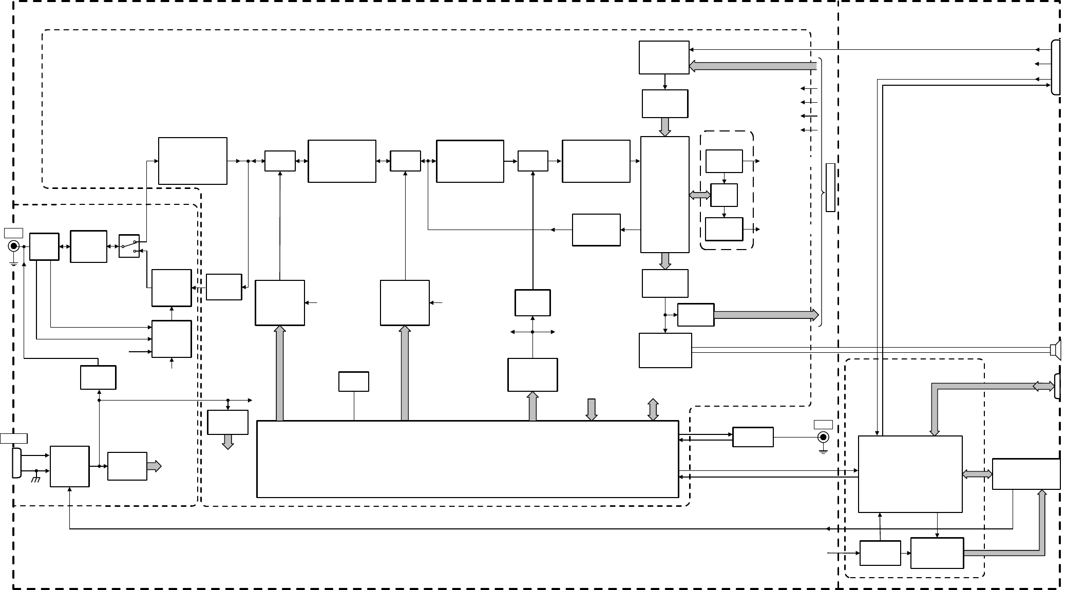
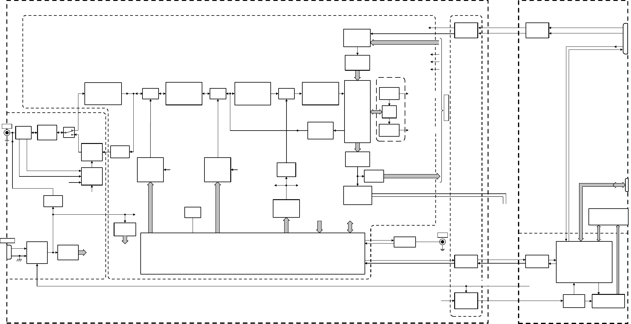
2-1.1.3 Functional Block Diagram
The functional block diagram of Micom-Z dash-mount version is shown in Figure 2-3.
2-1.1.3.1 Transmit Path
a. Selection of Signal Source. The transmit path can receive modulation signals from a
microphone connected to the front panel audio connector or signals from equipment connected
to the rear panel ACCESSORY connector (audio from an accessory device, a modem, or
telegraphy). Each source provides a different PTT signal, and therefore the selection of the
signal to be transmitted is made in accordance with the active PTT signal:
• MIC PTT – PTT from the microphone connected to the front panel connector, transmits the
voice signal provided by the microphone.
• Voice PTT – PTT from an accessory connected to Micom-Z through the ACCESSORY
connector, transmits the voice signal from the accessory device.
• Data PTT – PTT from a data device, for example, a modem, connected to Micom-Z through
the ACCESSORY connector, causes Micom-Z to switch to the data mode and transmit the
modem signal.
• CW PTT – PTT from a Morse key connected to Micom-Z through the ACCESSORY
connector, causes the radio to switch to the CW (Morse) transmission mode.
In parallel, the radio operating mode is automatically adapted for best performance with the
signal expected for the detected PTT type.
b. Processing of Transmit Signal. The selected audio modulation signal is converted to a digital
data stream by the A/D converter section of a codec, for processing by the DSP subsystem. The
DSP outputs a digital representation of the signal, in accordance with the modulation mode
selected by the operator (LSB, USB, AME or PILOT). This digital representation is converted
to the actual IF modulated signal, on a carrier frequency of 1.05 MHz, by a digital sideband
modulator (DSM).
c. ISB Option. When the ISB option is installed, the master sideband signal is processed as
explained above. In addition, the transmit signal received through the TX_AUDIO_ISB line of
the ACCESSORY connector is converted to a digital data stream by an additional codec. The
codec supplies the data stream to the DSP, which processes the signal in parallel with the other
(master sideband) data stream, and generates the representation of an ISB signal for the DSM.
d. Generation of RF Transmit Signal.
(1) The 1.05 MHz transmit IF signal generated by the DSM is converted by the second mixer
to 45.1 MHz, by mixing it with a 46.15 MHz local oscillator signal provided by
synthesizer 2 (para. 2-1.1.3.3).
The 45.1 MHz is filtered and amplified by the first IF processor.
(2) The 45.1 MHz IF transmit signal is down-converted to the desired RF frequency by the
first mixer. The conversion is performed by mixing the IF signal with the variable local
oscillator signal provided by synthesizer 1 (para. 2-1.1.3.3).
The resulting low-level RF signal is amplified by the exciter amplifier, and supplied to
the RF power amplifier in the HI POWER module.
MM-E 2072-09333-00
2-4
(3) The RF power amplifier in the HI POWER module generates an RF signal at the power
level selected by the operator (LOW, MED, HIGH, or MAX). The transmit signal is
connected by the TX/RX switch to the harmonic filter, which attenuates harmonics and
unwanted spurious signals. The filtered signal then passes to the ANT connector through
a power sensor, which generates DC voltages, VFWD and VREV, proportional to the
forward and reflected power.
The ANT connector can be connected either directly to a broadband antenna, or to an
external ATU unit. DC power for the ATU unit is provided from the internal protected
DC power line, through a switch controlled by the LORD module.
An automatic level control (ALC) loop maintains the transmit output power close to the
selected transmit power. The automatic level control loop compares the VFWD sample
with the transmit power control signal provided by the microcomputer subsystem in the
LORD module, and adjusts the input RF signal power reaching the amplifier.
The VREV sample is used for mismatch protection: if the VSWR (Voltage Standing
Wave Ratio) exceeds 2:1, the transmit power is proportionally reduced, to prevent
damage.
The RF power amplifier also includes thermal protection: when the internal temperature
exceeds the maximum permitted, the transmit power is automatically reduced until the
temperature returns to normal. If nevertheless the temperature continues to increase even
when operating at the LOW level, the transmission is stopped until the temperature
returns to normal.
2-1.1.3.2 Receive Path
a. Processing of Received RF Signal.
(1) The received RF signal is filtered by the harmonic filter, and is then connected by the
TX/RX switch to the preselector in the LORD module.
(2) The preselector provides further filtering of the RF signal, to improve the rejection of
out-of-band signals. The resulting signal is supplied to the first mixer, which converts the
signal to the first IF frequency, 45.1 MHz, by mixing it with the local oscillator 1 signal
provided by synthesizer 1 (para. 2-1.1.3.3).
b. IF Signal Path.
(1) The first IF processor filters and amplifies the 45.1 MHz provided by the first IF mixer.
The filtered signal is then converted to the second IF frequency, 450 kHz, by the second
mixer, which mixes the 45.1 MHz signal with the local oscillator signal provided by the
synthesizer 2.
(2) The second IF signal is filtered and amplified by the second IF processor, and is then
converted to the third IF frequency, 20 kHz, by the third mixer. The local oscillator signal
for the third mixer, 430.77 kHz, is obtained by dividing the 16.8 MHz reference
frequency.
(3) The third IF signal is converted to a digital data stream, which is supplied to the DSP
subsystem. The DSP demodulates the IF signal, and extracts the original modulation
signal.
c. Audio Signal Paths.
(1) The data stream demodulated signal, provided by the DSP, is converted by the D/A
converter section of the codec to an audio signal. The audio signal is amplified and
supplied to the speaker located on the front panel, and to the other audio and data outputs
in the ACCESSORY connector.
(2) When the ISB option is installed, the DSP provides an additional data stream which
represents the slave sideband. This data stream is converted by a codec to an audio signal,
RX_AUDIO_ISB, which is available in the ACCESSORY connector.
MM-E 2072-09333-00
Voice PTT
Audio and Data Sources
SPKR
MIC
Digital SSB
Modulator
(DSM)
Codec
D/A Section
Audio Receive
Circuits
Audio
Amplifier
Divider
by 39
16.8 MHz
Reference
Amplifier
Audio and Data Outputs
16.8 MHz
to DSP
16.8 MHz
Reference
Frequency
Local Oscillator 1
45.2 to 75.1 MHz
Local Oscillator 2
44.05 to 46.15 MHz
Local Oscillator 3
430.77 kHz
TX
Amplifier
Codec
RX
Amplifier
Synthesizer 1
16.8 MHz
Reference
Frequency
Frequency
Control Data
First IF (45.1 MHz)
Processor
Second
Mixer
Receiver Second IF
(450 kHz)
Processor
Synthesizer 2
Receiver Third IF
(20 kHz)
Processor
16.8 MHz
to PLLs
DSP
Subsystem
First
Mixer
Third
Mixer
ISB Option
Codec
A/D Section
Local
Regulators
CONTROL HEAD
MIC
MIC PTT
Control and
Status LInes
Microcontroller
SW_BATT
Body Assembly Front Panel Assembly
ACCESSORY
To
LORD
TX_AUDIO_ISB
RX_AUDIO_ISB
Audio Connector
Data PTT
CW PTT
Serial Control Channel
GPS
Receiver
Main
Microcomputer
Subsystem
Calibration
Data
Frequency
Control Data
Front Panel
GPS
Serial Control Channel
1.05 MHz
MIC PTT
Power
Amplifier
Harmonic
Filter
TX/RX
Switch
Preselector and
Receiver Front End
Processor
ATU DC
Switch
Exciter
Amplifier
ANT
+
_
VDC IN
HI POWER
Power
Control
Power
Sensor
ALC
VFWD
VREV
Temperature
Lighting and
Heating
Control
SW_BATT
ON/OFF
Switch
and
Protection
Regulated
Voltages
Regulated
Voltages
Local
Regulators
Switching
Regulator
Backup
Battery Analog
Indications
ON_OFF_CONT
SD Socket
Figure 2-3. Micom-Z Dash-Mount Version, Functional Block Diagram
2-5/2-6
MM-E 2072-09333-00
2-7
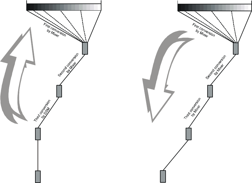
2-1.1.3.3 Frequency Conversion Subsystem
The Micom-Z frequency conversion scheme is described in Figure 2-4.
1.6 MHz
30 MHz
DSP processing
DSM
Audio
45.1 MHz
First IF amplifier
1.05 MHz
Second IF amplifier
0.1 MHz
30 MHz
DSP processing
Audio
20 kHz
Third IF amplifier
450 kHz
Second IF amplifier
45.1 MHz
First IF amplifier
A. Transmit Path B. Receive Path
Figure 2-4. Frequency Conversion Scheme
The conversion is implemented as follows:
• Transmit path: the analog section performs double frequency conversion, as shown in Figure 2-4.
• Receive path: the analog section performs triple frequency conversion, as shown in Figure 2-4.
Two synthesizers provide two local oscillator (LO) signals for the transmit and receive paths:
• The first LO signal covers the 45.2 to 75.1 MHz range in three subranges, and is generated by a
PLL (phase locked loop) using three VCOs (voltage controlled oscillators). Refer to Figure 2-5.
• The second LO signal is generated by a PLL covering the 44 to 46 MHz range with one VCO.
Refer to Figure 2-6.
In both synthesizers, the VCO frequencies are higher than the LO frequencies: to achieve the final
frequencies, the first synthesizer divides its output frequency by 2, and the second synthesizer divides
its output frequency by 8. Using frequency division decreases spurious levels without degrading the
lock-in time of the PLL, and also improves the frequency resolution.
Thus, the first synthesizer provides a resolution of 8.75 kHz, and the second synthesizer provides a
resolution of 1.25 kHz. The additional processing needed to achieve an overall frequency resolution of
10 Hz is performed by the DSP.
Both synthesizers use a single reference frequency, generated by a 16.8 MHz oscillator. As a result,
the overall radio frequency stability and accuracy are determined by the accuracy and stability of this
single reference oscillator.
The standard reference oscillator is a digitally temperature-compensated crystal oscillator (DTCXO).
An optional ovenized crystal oscillator (OCXO) with higher accuracy and stability can be ordered, for
enhanced frequency accuracy.
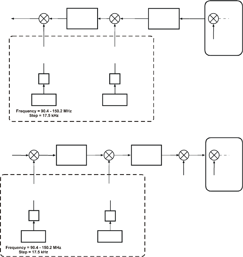
MM-E 2072-09333-00
2-8
IF Processor
45.1 MHz
RF Output
1.6 - 30 MHz
DSM
Synthesizer Subsystem
First LO
Frequency = 46.7 - 75.1 MHz
Step = 8.75 kHz
÷2
VCO 1, 2, 3
Frequency
Step = 10 kHz
= 368.4 MHz
Second LO
Frequency = 46.15 MHz
Step = 1.25 kHz
÷8
VCO 4
0 to 1.25 kHz
10 Hz Resolution
DSP
1.05 MHz
Figure 2-5. Transmit Path Frequency Conversion Scheme
RF Input
0.1 - 30 MHz
0 to 3 kHz
10 Hz Resolution
DSP
430.77 kHz
Synthesizer Subsystem
÷2
IF Processor
45.1 MHz
IF Processor
450 kHz
First LO
Frequency = 45.2 - 75.1 MHz
Step = 8.75 kHz
VCO 1, 2, 3
Frequency 352.4 - 369.2 MHz
Step = 10 kHz
=
Second LO
Frequency = 44.05 - 46.15 MHz
Step = 1.25 kHz
÷8
VCO 4
Figure 2-6. Receive Path Frequency Conversion Scheme
2-1.1.3.4 Control Subsystem
The Micom-Z control subsystem includes the main microcomputer subsystem located on the LORD
module, and a microcontroller located on the CONTROL HEAD module.
a. The CONTROL HEAD microcontroller provides the interface to the front panel keypad and
LCD, which enables the operator to control Micom-Z operation and monitor its status. In
addition, the microcontroller can also communicate with external equipment, for example, a PC
running the RSS or MRC utility, via an additional serial asynchronous control channel
terminated in the front panel audio connector.
The microcontroller communicates with the main microcomputer subsystem via a serial
asynchronous control channel. This serial channel is used to transfer the commands entered by
the operator using the front panel keypad, and data received via the serial control channel from
RSS or MRC (this data includes operational parameters, and radio set calibration data for the
transmit power and frequency accuracy).
In addition to the functions described above, the microcontroller also controls the LCD heating,
and the LCD and keypad backlighting.
The microcontroller supports the connection of an external memory card using the SD format,
which can be plugged into the SD socket at the top of the front panel.
MM-E 2072-09333-00
2-9
b. The main microcomputer subsystem in the LORD module controls the operation of all the
Micom-Z circuits, monitors their status, measures the various analog voltages that represent
power levels, temperatures, supply voltages, etc., and manages self-test.
The microcomputer subsystem uses the information received from the front panel
microcontroller and the PTT commands to select the desired operating mode, and stores the
operational parameters in a battery-protected memory. The calibration data is written into an
EEPROM, and therefore it is always preserved, even when backup battery is replaced.
The main microcomputer subsystem sends to the front panel microcontroller the data regarding
the current operational parameters and indications, for display on the front panel LCD.
The microcomputer subsystem also includes several UARTs, which can be used to
communicate with other equipment connected via the ACCESSORY connector, and via the
optional GPS receiver.
2-1.1.3.5 Power Supply Subsystem
The Micom-Z power source is connected via the VDC IN connector to the HI POWER module, which
includes the ON/OFF electronic switch and the input voltage protection circuits.
The ON/OFF switch, integrated with the protection circuits, is controlled by the ON_OFF_CONT line
from the front panel. It connects the supply voltage to the internal supply voltage line, SW_BATT,
when the operator turns the Micom-Z on, provided the polarity of the supply voltage is correct, and
within the allowed limits.
The SW_BATT line provides power to the local regulators on the various modules. The supply
voltage is also connected via current limiting devices to the ACCESSORY connector.
2-1.2 Micom-Z Trunk-Mount Version
2-1.2.1 Structure
The Micom-Z trunk-mount version consists of two main assemblies:
• Body assembly, shown in Figure 2-7. The Micom-Z trunk-mount version body assembly is
identical to the Micom-Z dash-mount version body assembly, but its front side has a cover that
carries the INTERCONNECTION module.
INTERCONNECTION
Front Cover
Connector for
Flat Cable
to LORD
LORD
RX Coaxial
Cable
TX Coaxial
Cable
Flat Cable
LORD - HI POWER
Rear Panel
HI POWER
Body Assembly
Flat Cable
GPS - LORD
GPS
Receiver
Backup
Battery
Internal GPS
Antenna Cable
Figure 2-7. Micom-Z Trunk-Mount Version, Structure of Body Assembly
The INTERCONNECTION module, which connects to the LORD module by a single flat cable,
provides the functions needed to enable connecting to the control head via a long cable.
MM-E 2072-09333-00
2-10
• Control head, shown in Figure 2-8. This is a separate unit that includes the operator interface and
CONTROL HEAD module, which are similar to the front panel of the Micom-Z dash-mount
version, except that the speaker is external. The access to the CONTROL HEAD module is
through a rear cover fastened by four screws to the front panel.
The control head is connected to the body assembly by a cable, which also includes a branch for
connecting an external speaker.
Front Panel
CONTROL HEAD
Module
Rear Cover
LCD
Figure 2-8. Micom-Z Trunk-Mount Version, Structure of Control Head
2-1.2.2 Wiring Diagram
Figure 2-9 shows the wiring diagram of the Micom-Z trunk-mount version.
a. Body Assembly. This assembly comprises the following main modules:
(1) LORD module: same as the Micom-Z dash-mount version module.
(2) HI POWER module: same as the Micom-Z dash-mount version module.
(3) INTERCONNECTION module: contains interface circuits that enable the microcomputer
system in the LORD module to communicate with that in the CONTROL HEAD module
via the interconnecting cable, an interface for the microphone signal, and a supply voltage
switch for the control head.
b. Control Head. This assembly comprises the CONTROL HEAD module, similar to the
CONTROL HEAD module in the dash-mount version, except that it includes interface circuits
that enable the module to communicate with the LORD module via the interconnecting cable.
The cable also provides the connection to an external speaker.
MM-E 2072-09333-00
2-11
LCD LORD
P501 J6
GPS
GPS
Receiver
J8
Backup
Battery
J4
HI POWER
J3
J1
P3
RX
P2
J2
TX
P4
J5
ACCESSORYANTVDC IN
E2
E1
J3
P2
P4
P6
Body AssemblyControl Head
Interconnection
Cable
INTERCONNECTION
P1P2
J4
Socket
for SD
Memory
Card
Speaker
Microphone
Figure 2-9. Micom-Z Trunk-Mount Wiring Diagram
2-1.2.3 Functional Block Diagram
The functional block diagram of Micom-Z trunk-mount version is shown in Figure 2-10.
2-1.2.3.1 Transmit Path
a. Selection of Signal Source. The transmit path can receive modulation signals from a
microphone connected to the audio connector of the control head, or signals from equipment
connected to the rear panel ACCESSORY connector (audio from an accessory device, a
modem, or telegraphy). Each source provides a different PTT signal, and therefore the selection
of the signal to be transmitted is made in accordance with the active PTT signal:
• MIC PTT – PTT from the microphone connected to the control head connector, transmits the
voice signal provided by the microphone. The microphone signal passes through a buffer,
which converts the signal to a balanced signal, for transmission to the body assembly through
the interconnection cable. Another buffer located on the INTERCONNECTION module
converts the balanced signal to a single-ended signal, which is supplied to the audio amplifier.
The PTT signal also passes through an RS-485 line driver, for transmission to the body
assembly through the interconnection cable. An RS-485 line receiver located on the
INTERCONNECTION module converts the balanced RS-485 signal to the internal logic
levels.
MM-E 2072-09333-00
2-12
• Voice PTT – PTT from an accessory connected to Micom-Z through the ACCESSORY
connector, transmits the voice signal from the accessory device.
• Data PTT – PTT from a data device, for example, a modem, connected to Micom-Z through
the ACCESSORY connector, causes Micom-Z to switch to the data mode and transmit the
modem signal.
• CW PTT – PTT from a Morse key connected to Micom-Z through the ACCESSORY
connector, causes the radio to switch to the CW (Morse) transmission mode.
In parallel, the radio operating mode is automatically adapted for best performance with the
signal expected for the detected PTT type.
b. Processing of Transmit Signal. See para. 2-1.1.3.1.b.
c. ISB Option. See para. 2-1.1.3.1.c.
d. Generation of RF Transmit Signal. See para. 2-1.1.3.1.d.
2-1.2.3.2 Receive Path
a. Processing of Received RF Signal. See para. 2-1.1.3.2.a.
b. IF Signal Path. See para. 2-1.1.3.2.b.
c. Audio Signal Paths. See para. 2-1.1.3.2.c. The only difference is that an external speaker is used
(this speaker is connected via a branch of the interconnection cable).
2-1.2.3.3 Frequency Conversion Subsystem
The Micom-Z frequency conversion scheme is described in para. 2-1.1.3.3.
2-1.2.3.4 Control Subsystem
The Micom-Z control subsystem includes the main microcomputer subsystem located on the LORD
module, and a microcontroller subsystem located on the CONTROL HEAD module, which are similar
to these described in para. 2-1.1.3.4. The only difference is the use of RS-485 transceivers that transfer
the control channel via the interconnection cable.
2-1.2.3.5 Power Supply Subsystem
The Micom-Z power source is connected via the VDC IN connector to the HI POWER module, which
includes the ON/OFF electronic switch and the input voltage protection circuits.
The ON/OFF switch, integrated with the protection circuits, is controlled by the ON_OFF_CONT line
from the control head. It connects the supply voltage to the internal supply voltage line, SW_BATT,
when the operator turns the Micom-Z on, provided the polarity of the supply voltage is correct, and
within the allowed limits. The SW_BATT line provides power to the local regulators on the other
modules. The supply voltage is also connected via current limiting devices to the ACCESSORY
connector.
The connection of the SW_BATT line to the control head passes through a supply voltage control
circuit, also controlled by the ON_OFF_CONT line: this circuit connects the supply voltage only
when the operator passes through control head ON/OFF button to turn the Micom-Z on. Therefore, if
the interconnection cable, or the control head, is disconnected from the body assembly, Micom-Z is
automatically turned off.
MM-E 2072-09333-00
Audio and Data Sources
SPKR
MIC
Digital SSB
Modulator
(DSM)
Codec
D/A Section
Audio Receive
Circuits
Audio
Amplifier
Divider
by 39
16.8 MHz
Reference
Power
Amplifier
Harmonic
Filter
Amplifier
Audio and Data Outputs
16.8 MHz
to DSP
16.8 MHz
Reference
Frequency
Local Oscillator 1
45.2 to 75.1 MHz
Local Oscillator 2
44.05 to 46.15 MHz
Local Oscillator 3
430.77 kHz
TX
Amplifier
Codec
RX
Amplifier
Synthesizer 1
16.8 MHz
Reference
Frequency
TX/RX
Switch
Preselector and
Receiver Front End
Processor
Frequency
Control Data
First IF (45.1 MHz)
Processor
Second
Mixer
Receiver Second IF
(450 kHz)
Processor
Switching
Regulator
SW_BATT
ON/OFF
Switch
and
Protection
Synthesizer 2
Receiver Third IF
(20 kHz)
Processor
16.8 MHz
to PLLs
DSP
Subsystem
First
Mixer
ATU DC
Switch
Regulated
Voltages
Exciter
Amplifier
Third
Mixer
ISB Option
Codec
A/D Section
CONTROL HEAD
MIC
MIC PTT
Control and
Status LInes
Microcontroller
SW_BATT
Body Assembly Control Head Assembly
ANT
+
_
VDC IN
HI POWER
ACCESSORY
To
LORD
TX_AUDIO_ISB
RX_AUDIO_ISB
Serial Control Channel
GPS
Receiver
Calibration
Data
Frequency
Control Data
GPS
Serial Control Channel RS-485
Transceiver
Supply
Voltage
Control
PTT and
MIC Buffers
MIC PTT
INTERCONNECTION
RS-485
Transceiver
Interconnection
Cable
Local
Regulators
Lighting and
Heating Control
Front Panel
ON_OFF_CONT
Audio Connector
PTT and
MIC Buffers
To External
Speaker
1.05 MHz
Power
Control
Voice PTT
Data PTT
CW PTT
Power
Sensor
ALC
VFWD
VREV
Temperature
Local
Regulators
Backup
Battery Analog
Indications
Main
Microcomputer
Subsystem
Regulated
Voltages
SD Socket
Figure 2-10. Micom-Z Trunk-Mount Version, Functional Block Diagram
2-13/2-14
MM-E 2072-09333-00
2-15
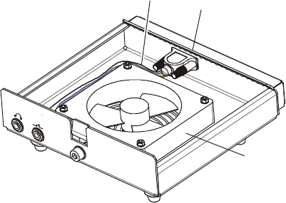
2-1.3 Micom-Z Cooling Tray
Figure 2-11 shows the structure of the Micom-Z cooling tray.
The cooling tray includes one module, the FAN CONTROL module, which provides point-to-point
connections between the two 25-pin connectors of the cooling tray. The module also includes the fan
control circuit, which enables to turn the supply voltage to the fan ON or OFF in accordance with the
control signal provided by the Micom-Z installed on the tray.
The connections between the radio side connector, the front panel jacks, and the fan are made by a
harness, which connects to the 9-pin D-type connector on the module.
Internal
Fan Cable
FAN CONTROL
Module
Cooling
Fan
Figure 2-11. Micom-Z Cooling Tray Structure
MM-E 2072-09333-00
2-16
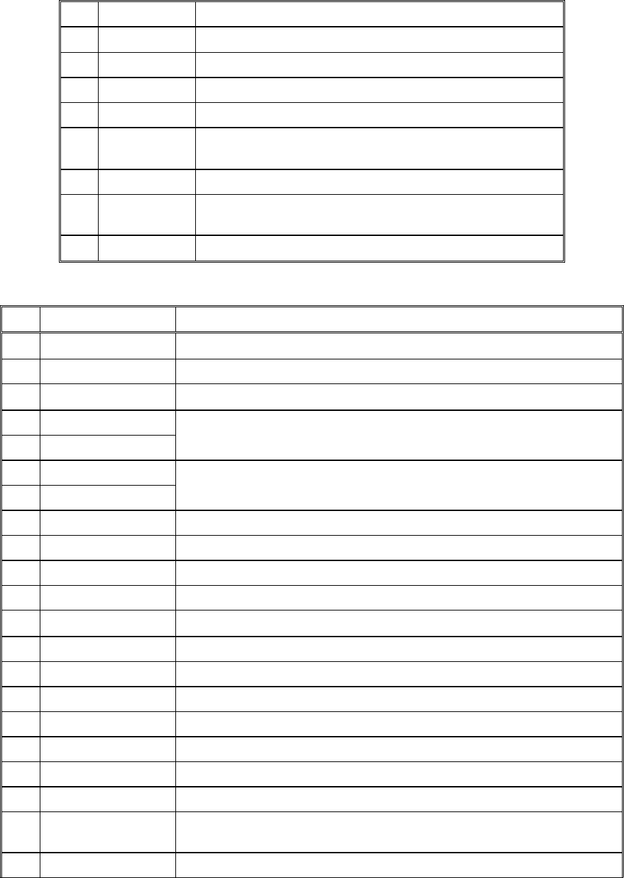
2-2. OPTIONS AND ACCESSORIES
The following tables list the options and accessories that can be ordered for Micom-Z. Contact the
manufacturer or your local representative if you need an option or accessory not listed below.
Table
2-1. Available Options
Option Mfg. Cat. No. Description
G434 2072-09870-30
PC-based control and programming software package
S809 2072-09048-00
Interface cable kit for CW key and headphones
G431 2072-09197-10
Internal GPS receiver with polling application
FRN8525 2072-09460-00
Vocoder with
digital audio quality enhancer (subject to export
license), includes interface cable and operator manual
FVN5228 2072-09780-00
Digital Advanced Encryption Standard
option for FRN8525
(subject to export license)
FRN8526 2072-09720-00
4800bps single-tone high speed data modem (MDM4800)
with
Micom-Net E-mail Gateway software package
FVN5229 2072-09790-00
Digital Advanced Encryption Standard
option for FRN8526
(subject to export license)
FRN8527 2072-09820-00
4800bps single-tone high speed data modem (MDM4800)
with
Micom-Net E-mail Gateway software package
integrated with
vocoder and digital voice quality enhancer
FVN5230 2072-09800-00
Digital Advanced Encryption Standard option for FRN8527
(subject to export license)
Table
2-2. Accessories
Option Mfg. Cat. No. Description
Mobile Station Accessories
FAD1410 2072-09010-20
Automatic tuning whip antenna
F2265 2072-09030-10
Automatic antenna tuner
FAD1400 2072-92270-10
12 ft whip antenna (not required for FAD1410)
FLN3660 2072-90174-00
Cooling tray
FLN2818 2072-09676-00
1.6 – 30MHz, 125W PEP/average
heavy duty automatic antenna
tuner for fixed and mobile installations, for use in
data system
applications. Includes 30m RF coaxial cable and operator
manual
(requires long wire or whip antenna)
HSN1600 2072-90410-00
External speaker
Fixed Station Accessories
FMN5542 2072-09803-00
Desk microphone
– 2072-09031-10
Kit for continuous duty data transmission, includes junction box
FPN5600 2072-09736-00
110/220VAC AC power supply
MM-E 2072-09333-00
2-17
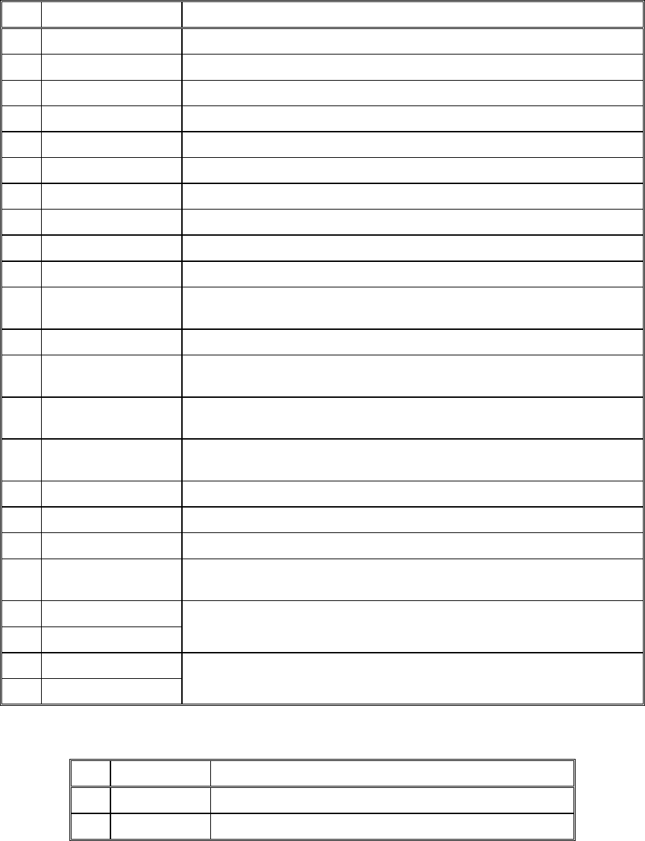
2-3. CONNECTOR DATA
2-3.1 Micom-Z Connector Data
Table
2-3. Micom-Z Microphone Connector, Pin Functions
Pin Designation Description
1 SWA+ Power output to the microphone
2 RXD Serial communication line (input)
3 TXD Serial communication line (output)
4 GND Ground line
5 MIC AUDIO Input audio signals generated by the microphone (600 Ω
impedance; 300 mV tone is required for full output power).
6 PTT MIC Activates transmission by short to ground.
7 MONITOR Mutes the speaker before transmission is enabled (short
momentary to ground to open speaker).
8 AUDIO OUT Receive audio output to earphone (600 Ω, 300 mVRMS)
Table
2-4. ACCESSORY Connector Pin Functions
Pin Designation Description
1 SPKR- Differential output to external 8Ω, 5W speaker
2 STOP SCAN Digital control input for stop scan function (optional function)
3 SPKR+ Differential output to external 8Ω, 5W speaker
4 EXT RX AUDIO+
5 EXT RX AUDIO-
Differential received audio output (0 dBm/600Ω; not controlled by
volume)
6 EXT TX AUDIO+
7 EXT TX AUDIO-
Differential transmit audio input (600Ω input impedance, 0 dBm is
required for full power)
8 PTT IN VOICE Transmission command (short to ground) for voice signals
9 PTT IN DATA Transmission command (short to ground) for data signals
10
PTT IN CW Transmission command (short to ground) for CW (Morse) signals
11
SW A+ Primary DC voltage current limited output (max 1A)
12
DSI/KW CC BDM – Data serial in/optional external amplifier channel change
13
KW ON/OFF Optional external amplifier power on/off output
14
REV CLOSE LOOP Close the radio ALC loop (input from optional external amplifier)
15 RXA Receive input (point-to-point protocol to host/HLC)
16
TXA Transmit output (point-to-point protocol to host/HLC)
17
EX RESET External RESET input (for BDM)
18
GND Ground
19
KW PTT PTT output to optional external amplifier (active low)
20
EXT ALARM External alarm output (open collector, pulled to ground when external
alarm is activated)
21 VPP Flash programming voltage, input to BDM
MM-E 2072-09333-00
2-18
Table
2-4. ACCESSORY Connector Pin Functions (Cont’d)
Pin Designation Description
22
DSC/KW_ALC BDM – Data serial clock/optional external amplifier ALC
23
SQ GATE Squelch open/closed indication output
24
DSO/FAN_ON_OFF
BDM – Data serial out/Fan control
25
FREEZE/KW TUNE
BDM – Freeze/optional external RF power amplifier tune
26
GND Ground
27
FWD CLOSE LOOP ALC radio loop closure input (from optional external amplifier)
28
RXC Receive input (point-to-point protocol to host/HLC)
29
TXB RS-232 transmit output to “smart” external accessories
30
AMP REV Maintain constant power at transceiver output (optional function)
31
RXD Receive input (point-to-point protocol to host/HLC)
32 TX AUDIO OUT Input to LORD baseband TX path from external device (for example,
modem)
33 RXB RS-232 protocol receive input to “smart” external accessories
34
RX AUDIO OUT Input to LORD baseband RX path from external device (for example,
modem)
35 RX AUDIO IN Output from LORD baseband RX path to external device (for example,
modem)
36 AMP FWD Maintain constant power at transceiver output (from optional external
amplifier)
37 VP PTT PTT output (active low) (optional function)
38 TXD Transmit output (point-to-point protocol to host/HLC)
39 TXC Transmit output (point-to-point protocol to host/HLC)
40 TX AUDIO IN Output from LORD baseband TX path to external device (for example,
modem)
41 EXT RX AUDIO(2)+
42 EXT TX AUDIO(2)-
Audio output from the optional ISB processor (secondary sideband)
43 EXT RX DATA-
44 EXT RX DATA+ Baseband output (0 dBm, 600 Ω), unsquelched
Table
2-5. Micom-Z VDC IN Power Connector, Pin Functions
Pin Designation Description
1 Power Positive input line
2 Ground Return (negative) line
MM-E 2072-09333-00
2-19
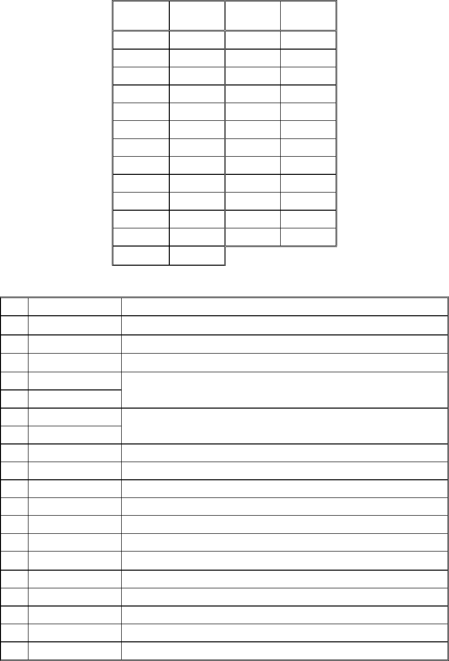
2-3.2 Cooling Tray Connectors
Table
2-6. Micom-Z 44-Pin/25-Pin Adapter Cable Wiring Diagram
44-Pin
Connector
25-Pin
Connector
44-Pin
Connector
25-Pin
Connector
1 1 43 14
44 2 15 15
3 3 16 16
4 4 17 17
5 5 18 18
6 6 19 19
7 7 20 20
8 8 21 21
9 9 22 22
10 10 23 23
11 11 24 24
12 12 25 25
13 13
Table
2-7. Cooling Tray 25-Pin ACCESSORY Connector Pin Functions
Pin Designation Description
1 SPKR- Differential output to the external 8Ω, 5W speaker
2 EXT RX DATA+ Baseband output (0 dBm, 600Ω) to external device, unsquelched
3 SPKR+ Differential output to the external 8Ω, 5W speaker
4 EXT RX AUDIO+
5 EXT RX AUDIO-
Differential receive audio output (0 dBm, 600Ω; not affected by the
volume control, but controlled by the squelch)
6 EXT TX AUDIO+
7 EXT TX AUDIO-
Differential transmit input (600Ω input impedance; 0 dBm is required for
full power)
8 PTT IN VOICE Transmission command (short to ground) for voice signals
9 PTT IN DATA Transmission command (short to ground) for data signals
10
PTT IN CW Transmission command (short to ground) for CW (Morse) signals
11
SW A+ Primary DC voltage current limited output (max. 1A)
12
DSI/KW CC BDM – Data serial in/optional RF power amplifier channel change
13
KW ON/OFF Optional RF power amplifier power on/off output
14
EXT RX DATA- Baseband output (0 dBm, 600Ω) to external device, unsquelched
15 RXA Receive input (point-to-point protocol to host/HLC)
16
TXA Transmit output (point-to-point protocol to host/HLC)
17
EX RESET External RESET input (for BDM)
18
GND Ground
19
KW PTT OUT PTT output to optional RF power amplifier (active low)

MM-E 2072-09333-00
2-20
Table
2-7. Cooling Tray 25-Pin ACCESSORY Connector Pin Functions (Cont’d)
Pin Designation Description
20
EXT ALARM External alarm output (open collector, pulled to ground when external
alarm is activated
21 VPP Flash programming voltage, input to BDM
22
DSC/KW_ALC BDM – Data serial clock/optional RF power amplifier ALC
23
SQ GATE Squelch open/closed indication output
24
DSO/FAN ON/OFF
BDM – Data serial out/fan control
25
FREEZE/KW TUNE
BDM – Freeze/kW amplifier tune
MM-E 2072-09333-00
2-21
Section II. CIRCUIT ANALYSIS
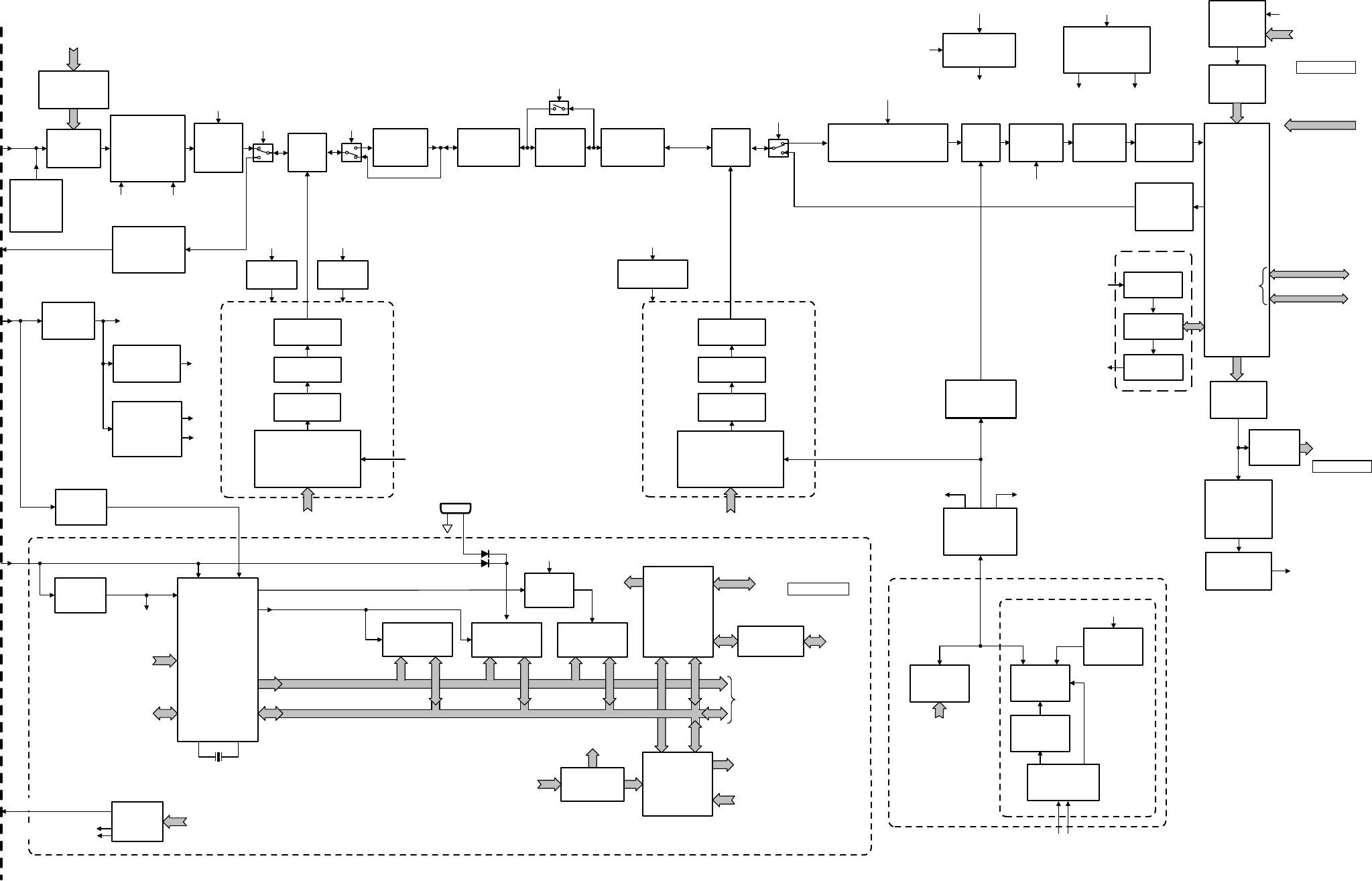
2-4. LORD MODULE
The schematic circuit diagram of the LORD module is shown in Figure A-1, and the module block
diagram is shown in Figure 2-12.
2-4.1 Audio Subsystem
Refer to Figure A-1.C. The audio subsystem uses the 8V_AUDID_ISB voltage, provided by the linear
voltage regulator U6098, and a bias voltage, 4V_AUDID_BIAS, generated by part of U4000.
2-4.1.1 Audio Transmit Path
a. Microphone Signal Path. The MIC_IN signal from the front panel passes through the analog
switch in U6085 to an amplifier, followed by a voiceband bandpass filter in U4003. The
resulting signal is sent to the codec U6040 via the MIC line.
b. EXT_TX_AUDIO Signal Path. The EXT_TX_AUDIO signal from the ACCESSORY
connector is converted to a single-ended signal by an amplifier in U4000, and then is connected
through the analog switches in U6085 to the microphone signal path.
2-4.1.2 Audio Receive Path
a. SPKR Signal Path. The RX_AUDIO signal received from the codec U6040 is converted to a
single-ended signal by an amplifier in U4003, passes through an analog switch in U6084 to the
digitally-controlled potentiometer U6081, which serves as a volume control.
U6081 output is connected by another section of U6084 to an amplifier in U4000, which drives
the audio power amplifier U4002. U4002 balanced output signal, SPKR, is sent to the front
panel assembly.
b. Baseband and Modem Signal Outputs. The single-ended RX_AUDIO output signal is directly
connected to a driver built around U6082, which drives the balanced EXT_RX_DATA lines in
the ACCESSORY connector.
In addition, the signal can also be connected via analog switches in U6084 to another driver
built around U6082, which drives the balanced EXT_RX_AUDIO lines in the ACCESSORY
connector.
2-4.2 DSP Subsystem
Refer to Figure A-1.D.
The main supply voltage for the DSP subsystem, +3.3V, is provided by a linear voltage regulator,
U6097.
2-4.2.1 Transmit Path
a. The modulation signal, MIC, is applied to the input, INP, of the analog/digital conversion
section of the coder, U6040. This section includes an anti-aliasing filter, followed by a
programmable gain amplifier. The resulting signal is converted to a digital data stream, DOUT,
at a rate determined by the MCLK (main clock) signal received from a timer, TI02, in the DSP
U6042. The codec operates in the pulse mode, that is, it generates a continuous stream of bits
that represent the modulation signal.
The codec data stream, DOUT, and the associated clock, SCLK, are supplied to the enhanced
synchronous serial interface (ESSI 1) of the DSP.
b. DSP Functions. The DSP, U6042, is a digital signal processor with a 24-bit core. Its clock
signal is 16.8 MHz, received from the frequency reference generator via the DSP_16.8MHz. It
is controlled by the microcontroller, U5008, via the data and address buses, which connect to
MM-E 2072-09333-00
2-22
the DSP host port interface, and by a few discrete control lines. The RAM U6038 connected to
the DSP, address and data buses, is used by the DSP to store temporary variables and data.
The DSP has two ESSIs: ESSI 1 is used to connect to the codec U6040, and ESSI 0 is used to
connect to the DSM, U6000.
The operations performed by the DSP are determined by the program data loaded from the
microcontroller through the HPI. After processing the data stream received from the codec, the
DSP sends the resulting data stream, through ESSI 0, to the DSM, U6000.
c. DSM Functions. The DSM is a special-purpose digital processing component that converts the
incoming serial data stream to an analog signal, DSM_OUT. U6000 uses the same clock
frequency as U6042, 16.8 MHz.
The DSM_OUT signal is generated by an A/D converter, comprising a weighted network of
resistors connected to DSM FIR outputs.
The resulting signal is the transmit IF, an SSB (or AME) signal (in accordance with the
modulation mode selected by the user), on a 1.05 MHz virtual carrier.
2-4.2.2 Receive Path
a. The receive path of the DSP subsystem receives the digital stream representing the third IF
signal, generated by the serial output A/D converter, U1115. This stream, A_D_DATA, is
connected to the receive input, SRD0, of ESSI 0. U1115 conversion rate and timing are
synchronized by the clock and strobe signals, SR_CLK and CONVST, provided by the DSP.
The DSP can also control the operation mode of U1115, via the serial data stream SR_DATA.
b. The DSP processes the received data streams, and converts it to a data stream that represents the
demodulated IF signal. This stream is sent via ESSI 1 to the input, DIN, of the digital/analog
conversion section of the codec U6040.
The resulting analog signal is provided as a balanced signal at the OUTP and OUTM outputs.
These outputs are connected via the RX_AUDIO line to the audio receive path (para. 2-4.1.2).
2-4.3 ISB Option
Refer to Figure A-1.E.
The ISB option includes a codec, U6088, similar to U6040.
a. The A/D conversion path of U6088 processes the slave sideband signal, received from the
ACCESSORY connector via EXT_TX_AUDIO_ISB line. This signal is amplified and filtered
by U6089. The resulting data stream is sent to the DSP via the HYB_ESSI_STD line.
b. The D/A conversion path of U6088 receives the serial HYB_ESSI_SRD data stream from the
DSP, and converts it to a balanced audio signal. This signal is amplified by U6089, and sent to
the ACCESSORY connector via the EXT_RX_AUDIO_ISB line.
2-4.4 IF and RF Transmit Path
Refer to Figure A-1.M, Figure A-1.N, Figure A-1.P.
a. The 1.05 MHz signal generated by the DSM passes through a bandpass filter to the IF RX/TX
switch. In the transmit mode, CR1905 is forward biased and connects the signal to the second
mixer, U1108.
b. U1108 mixes the signal with the local oscillator signal, TX_SEC_INJ, provided by
synthesizer 2 (para. 2-4.7.3). The resulting signal, TRANS_IF, at 45.1 MHz, is applied to the
transmit section of the bidirectional IF amplifier, Q1006.
c. The amplified signal passes through the crystal filters FL2, FL1. The filtered signal bypasses the
first IF amplifier, Q1001, via the PIN diode switch CR1011, CR1012, and reaches the first
mixer, U1000.
MM-E 2072-09333-00
SPKR
to Speaker
via J6
MIC
to J6
Synthesizer 2
Frequency Control Data
Preselector
CR1-CR16
Front-End
Attenuator
(RAGC)
Q1000,
Q1013-Q1015
CR1000, CR1008
Front-End
Amplifier
Q1002,
Q1007
First
Mixer
U1000
First
IF Amplifier
Q1011
45.1 MHz
Crystal Filter
FL1, FL2
Bidirectional
IF Amplifier
Q1003, Q1006
Second IF Processor
Q1020-Q1023, FL3, FL4
20 kHz
Amplifier
P/O U1110
Antialias
Filter
P/O U1110
A/D
Converter
U1115
Digital SSB
Modulator
(DSM)
U6000
Codec
D/A Section
P/O U6040
Audio Receive
Circuits
P/O U4000,
P/O U4003,
U6081
Audio Power
Amplifier
U4002
Codec
A/D Section
P/O U6040
Audio
Amplifier
P/O U4000,
U4003
MIC
Divider by 39
U1113, U1114,
U1109
Buffers
and Filters
Q3001, Q3002
352.4-369.2 MHz
PLL
U6076, Q2007
Exciter
Amplifier
Q1004, Q1005
45.1 MHz 450 kHz
Amplifier
U6082,
P/O U4003
SINE_16.8 MHz
Reference Frequency
IF_16.8 MHz
Reference Frequency
SINE_16.8 MHz
Reference Frequency
Local Oscillator 2
44.05 to 46.15 MHz
Local Oscillator 3
430.77 kHz
1.05 MHz
DSP
Subsystem
U6042, U6038
90.2-150.4 MHz
PLL
U6075, Q2006, Q9040,
Q9020, Q9000,
Q9063-Q9065
Amplifier
U2002
Divider by 2
U2009
Bandpass
Filter
Synthesizer 1
Frequency Control Data
BIT Noise
Generator
Q9, Q30,
Q2901
RF IN Second
Mixer
U1108
Bypass
Switch
9T
30 dB
Attenuator
Q1019
STEP_AGC_30
RF RX/TX
Switch
9R
CR1904,
CR1905
Third
Mixer
U1111
Local Oscillator 1
45.2 to 75.1 MHz
TX Amplifier
P/O U6089
Codec
U6088
RX Amplifier
P/O U6089
ISB Option
RX_AUDIO_ISB
to J5
TX_AUDIO_ISB
to J5
DSP_16.8 MHz
to DSP
TX
9T
CR1011,
CR1012
RX_AUDIO
Audio Circuits
Supply
U6098,
P/O U4000
8V_AUDIO_ISB 4V_AUDIO_ISB
SW_A+
STEP_AGC_10 STEP_AGC_20
Band Selection
Control
U1, Q1-Q8
Preselector
Control Data
+5V Reg.
U6024
SW_A+
Amplifier
U2003
Divider by 8
U2010
Bandpass
Filter
+5V Regulator
U6025
SW_A+
Power-Up
Control
U5014
Flash Memory
U5001, U6035
SRAM
U5009, U5010
EEPROM
U6043
Address Bus (ADDR0-19)
Data Bus (DATA0-15)
Microcontroller
U5008
R/W
Y5000 or Y5002
38.4 kHz
XTAL EXTAL
I/O
Ports
Control and
Status Lines
To other
Circuits
RESET
Input/Output
Ports
U6068, U6069,
U6070
I/O Decoder
U6079
To UARTs
Control
Signals
Status and
Input Signals
Calibration
Data
Crystal
Oscillator
U3001
16.8 MHz Reference Generator
OCXO
U3002
or
D/A
Converter
U3010
Heater
Control
U3000, Q3000
OVEN_TEMP_CONT
from U1104
HEAT_CONT
10V
Regulator
U3004
SW_A+
SW_A+
+6V Reg.
U2004
To
HI POWER
+9V
Regulator
U1106
SW_A+
9V
+5V Regulator
U1107 VDD
9T/9R
Generator
U1100, Q1008,
Q1109, Q1017,
Q1018
9R
9T
+5V
Regulator
U6021
VRH
VCC
RF Power and
Oven Temp
Control Data
D/A
Converter
U1104
ADDR9-11
VCC
GPS Interface
U5007, U5006
To GPS
Receiver
(Option)
via J8
Main Microcomputer Subsystem
3.3V Regulator
U6097
+3.3V
to DSP Subsystem
VCC (+5V)
VCC
BIAS_OUT
OVEN_TEMP_CONT
To Control Head via J6,
and to ACCESSORY J5
EEPROM
Access
Control
Write Protect
IF RX/TX
Switch
9T
OCXO
Option
CR5004
CR5000 INT to
U5008
UART Unit
U6062, U6063,
U6078
To Backup
Battery
J4
+
_
Analog
Indications
A/D Converter
Inputs
TX Audio
and Data
Sources from
ACCESSORY
J5
RX Audio
and Data
Sources to
ACCESSORY
J5
PTT Signals to
U5008 via J5, J6
Data Bus
Address Bus
HPI
To DSP
HPI
STEP_AGC_30_2
STEP_AGC_10_2
Figure 2-12. LORD Module, Block Diagram
2-23/2-24
MM-E 2072-09333-00
2-25
d. The first mixer converts the 45.1 MHz transmit IF signal to the final RF transmit frequency, by
mixing with the local oscillator signal, FIRST_INJ, provided by synthesizer 1 (para. 2-4.7.2).
e. In the transmit mode, the mixer output signal passes through the PIN diode CR1010 to the
exciter amplifier (CR1009 is reverse-biased).
f. The mixer output signal is filtered by a low-pass filter, and is then amplified by Q1004, Q1005.
Q1012 and Q1010 provide the bias current for Q1004, Q1005 (bias current is provided only in
the transmit mode, under the control of the 9R line).
g. The amplified RF drive signal, at the collector of Q1005, is coupled to the HI POWER module
via the TX line.
CR1001 provides a DC voltage proportional to the drive signal peak level, PWR_LEVEL,
which is monitored by U5008 via the PAD6/AN6 input of its internal A/D converter.
2-4.5 RF Front End
Refer to Figure A-1.H, Figure A-1.I, Figure A-1.N.
2-4.5.1 Preselector
a. The preselector receives the RF IN signal from the HI POWER module via J1. CR2008,
CR2009, VR4 and VR5 protect against excessive signal levels.
b. During receive path self-test, the BIT noise generator can be activated by a low level on the
NOISE_CONTROL line; to add noise to the signal appearing on the RF IN line.
c. The RF IN signal passes through a low-pass filter to the preselector. The preselector consists of
seven high-pass filters, and an additional non-selective branch. The desired filter is inserted in
the received signal path by two sets of PIN diode switches: CR1 to CR8 at the input, and CR9 to
CR16 at the output.
The pair of PIN diodes corresponding to the operating frequency band is turned on by control
signal received via the SPI interface, U1: U1 is a serial/parallel converter, which converts the
serial preselector control word received via the SPI_DATA_OUT line to discrete control signals
for the PIN diode drivers, Q1 to Q8 (a pair of PIN diodes is turned on when the corresponding
driver is turned on by a high level at the corresponding U1 output).
d. The preselector output signal, PS_OUT, is connected to the RAGC attenuator. The RAGC
attenuator consists of two sections: a 10-dB attenuator (series resistors R1016, R1017) and a
20-dB attenuator (the series resistors and the shunt resistor R1023), which can be inserted in the
signal path by the PIN diode switches CR1000 and CR1008. These PIN diode switches are
controlled by the STEP_AGC_10 and STEP_AGC_20 lines, via the drivers Q1000, Q1013 to
Q1015.
The lines used to control the AGC step attenuators are generated by a serial/parallel converter,
U1112, using the data received via the SR_DATA line (the data updates the control lines status
when the CONVST line assumes a low level).
e. The RF signal is applied to the front-end amplifier, Q1002, which operates only in the receive
mode (its bias voltage is connected by Q1007 only in the receive mode, under the control of the
9T line).
f. The amplified signal passes through a low pass filter, a 9-dB attenuator pad and the PIN diode
CR1009 to the first mixer, U1000 (CR1010 is reverse-biased via the 9R line).
U1000 converts the RF signal to the first IF, 45.1 MHz, by mixing with the FIRST_INJ signal
provided by synthesizer 1 (para. 2-4.7.2).
MM-E 2072-09333-00
2-26
2-4.6 Receive IF Path
Refer to Figure A-1.M, Figure A-1.N.
2-4.6.1 First IF Processor
a. The 45.1 MHz IF signal generated by U1000 is amplified by Q1001 (the PIN diodes CR1011
and CR1012 are reverse-biased). The bias voltage for Q1001 is provided by Q1011, which is
turned on in the receive mode by the low level on the 9T line).
b. The amplified signal at the drain of Q1001 passes through an attenuator pad to the 45.1 MHz
bandpass crystal filters FL1 and FL2.
c. The filtered signal is amplified by the receive section, Q1003, of the IF bidirectional amplifier.
The resulting signal is applied to the second mixer, U1108, via the TRANS_IF line.
The STEP_AGC_30 control line is used to add an attenuation of 30 dB (when a high level is
provided by U1112) in the receive signal path, by reducing the input impedance and gain of the
amplifier stage built around Q1003.
2-4.6.2 Second IF Processor
a. The second mixer, U1108, converts the 45.1 MHz IF signal to the second receive IF frequency,
450 kHz, by mixing it with the TX_SEC_INJ signal provided by synthesizer 2 (para. 2-4.7.3).
b. In the receive mode, the PIN diode CR1904 is forward-biased, and CR1905 is reverse-biased.
This connects the 450 kHz IF signal to the second IF processor, comprising Q1021, the 450 kHz
bandpass crystal filter FL4, Q1022, the 450 kHz bandpass crystal filter FL3, and the output
amplifier Q1021.
R1832 is used to adjust the gain of the receive path to the prescribed value.
c. The gain of Q1021 can be reduced, as part of the operation of the 30-dB step attenuator, by
applying a low level on the STEP_AGC_30_2 line provided by U1112 (this turns off Q1020).
2-4.6.3 20 kHz IF Processor
a. The 450 kHz IF signal provided by Q1021 is applied to the third mixer, built around the quad
analog switch, U1111. U1111 operates as a balanced mixer, which converts the 450 kHz signal
to 20 kHz (nominal) by mixing it with 430.77 kHz. The 430.77 kHz signal is provided by the
divider by 39, U1113, U1114, via the duty cycle equalizer comprising the Schmitt trigger
inverters in U1109.
b. The two complementary waveforms generated by the two branches of the mixer U1111 are
combined by an amplifier in U1110, and then amplified by a variable-gain amplifier, also part
of U1110. The gain is controlled by the STEP_AGC_10_2 line provided by U1112 (a high level
reduces the gain).
c. The amplified 20 kHz passes through an antialiasing filter, part of U1110, and then it is
converted to a digital data stream by the A/D converter U1115 (para. 2-4.2.2.a).
2-4.7 Synthesizer Subsystem
Refer to Figure A-1.J, Figure A-1.K.d, Figure A-1.L.
2-4.7.1 Frequency Reference
Depending on the installed option, the reference frequency, 16.8 MHz, is generated either by the
DTCXO, U3001, or by the OCXO, U3002.
2-4.7.1.1 DTCXO Option
U3001 is a 16.8 MHz digitally temperature compensated crystal oscillator. Its frequency is controlled
via the SPI port: the temperature compensation data is received via the SPI_DATA_OUT line, and it is
latched into U3001 on the rising edge of the PENDULLUM_SEL line.
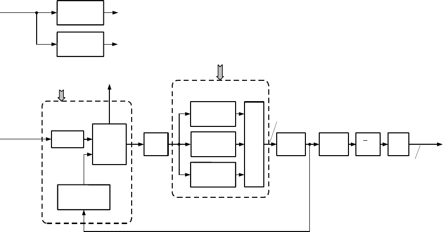
MM-E 2072-09333-00
2-27
U5008 can measure the voltage proportional to the ambient temperature near the oscillator (provided
by the thermistor R3023) by means of its internal A/D converter, through the AMB_TEMP line
connected to the AN5/PDA5 input.
2-4.7.1.2 OCXO Option
U3002 is an ovenized crystal oscillator, which includes circuits that enable to maintain the oscillator at
a constant temperature, higher than the ambient. The power for the OCXO is provided by a +10V
linear voltage regulator, U3004.
a. Temperature Control Loop. When U3002 is installed, its temperature indication output,
TEMP_SENSE, is compared by a differential amplifier built around U3000 with the
OVEN_TEMP_CNTL voltages provided by D/A converter U1104. The resulting error voltage
is amplified, and used to drive, via Q3000, the HEAT_CONT input of the OCXO. The current
flowing through Q3000 is monitored by the OCXO using R3024, R3025, via the CUR_SENSE
input.
b. Frequency Adjustment. The microcontroller U5008 adjusts the OCXO frequency in accordance
with the stored calibration data. The required information is sent via the SPI_DATA_OUT, and
it is latched in the D/A converter U3010 on the rising edge of the PENDULLUM_SEL line. The
resulting DC voltage is applied to the D2A_FREQ input of U3002.
2-4.7.1.3 Distribution of 16.8 MHz Reference Frequency
The squarewave provided by U3001 or U3002 is connected to two amplifiers, Q3001 and Q3002:
a. The signal developing at the collector of Q3001 is filtered by a bandpass filter and applied on
the IF_16.8MHz line. The IF_16.8MHz line is converted to a squarewave by the Schmitt trigger
in U1109, for use as the frequency reference for synthesizer 2; in addition, the signal passes
through an additional Schmitt trigger in U1109 to the DSP_16.8MHz line, for the DSP
subsystem.
The output signal of the Schmitt trigger is also applied to the clock inputs of the 4-bit
programmable counters U1113, U1114, which operate as a divider by 39 (para. 2-4.6.3).
b. Q3002 receives the signal through a bandpass filter, and provides the SINE_16.8MHz reference
signal for synthesizer 1.
2-4.7.2 Synthesizer 1
The functional block diagram of synthesizer 1 is shown in Figure 2-13.
U6075
Reference
Divider
Phase,
Frequency
and
Lock
Detector
Programmable
Divider
CP
FIN
Loop
Filter
SINE_16.8MHz
PLL1 Control Data
+5V Regulator
U6024
+6V Regulator
U2004
SW_A+RF VOS
VP1
FO_LD
Lock Indication
OSC_IN
VCO 3
126-150.2 MHz
Q9040, Q9065
VCO 2
107-126.5 MHz
Q9020, Q9064
VCO 1
90.4-107 MHz
Q9000, Q9063
Filter FIRST_INJ
VCO Selection
(FILT_VCO_SEL)
2
U2009
.
.
PIN Diode Switch
CR2001-CR2003
VCO Bank
Amplifier
Q2006
Amplifier
U2002
90.4 to 150.2 MHz,
in 17.5 kHz steps
46.7 to 75.1 MHz,
in 8.75 kHz steps
Figure 2-13. Synthesizer 1, Functional Block Diagram
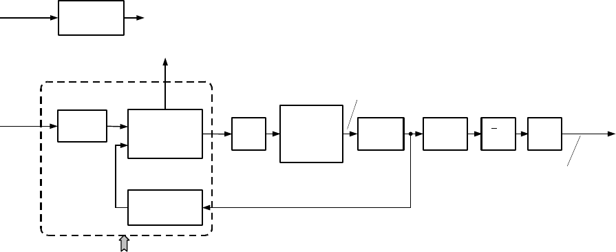
MM-E 2072-09333-00
2-28
a. PLL Control. Synthesizer 1 is a PLL using the frequency synthesizer control subsystem U6075
to generate a control voltage for one of the three VCOs used to cover the required frequency
range.
The control voltage is derived by the loop filter C2142, C2117, R2047, R2045, C2118, which
integrates the pulses appearing at the phase/frequency detector output, CP. These pulses are
generated by comparing the reference frequency connected to the OSC_IN input with a sample
of the selected VCO output, connected to the FIN input. Both signals undergo frequency
division inside U6075: the division ratio is determined by the data carried by the SR_DATA
line, when the PLL_1_SEL line rises to a high level.
b. VCO Selection. The VCO corresponding to the current operating frequency range is enabled by
a high level applied on the corresponding FILT_VCO_SEL line. A high level also turns on the
corresponding PIN diode, CR2001 to CR2003, thereby connecting the VCO output signal to the
amplifier, Q2006. A sample of the Q2006 output signal is connected to the FIN input of U6075,
to close the PLL loop.
c. Output Circuits. The output signal of Q2006 is also applied to the amplifier U2002. U2002
output signal drives the clock input of the divider by 2, U2009. U2009 output is filtered by a
bandpass filter, and connected via the FIRST_INJ line to the first mixer.
d. The regulated supply voltages needed by the synthesizer 1 are provided by two linear regulators,
built around U2004 and U6024.
e. The FO_LD lock indication provided by U6075 is combined by CR2000 with the lock
indication of U6076, to obtain the SYNTH_LOCK synthesizer status line (high level indicates
loss of lock).
2-4.7.3 Synthesizer 2
Figure 2-14 shows the functional block diagram of the synthesizer 2.
U6076
Reference
Divider
Phase,
Frequency
and
Lock Detector
Programmable
Divider
CP
FIN
Loop
Filter
VCO 4
Q9060
Amplifier
Q2007
Amplifier
U2003 Filter
16.8 MHz TX_SEC_INJ
PLL2 Control Data
+5V Regulator
U6025
SW_A+RF VOS2
FO_LD
Lock Indication
OSC_IN
8
U2010
.
.
TX: 368.4 MHz, 10 kHz steps
RX: 352.4 to 369.2 MHz, 10 kHz steps
TX: 46.15 MHz, 1.25 kHz steps
RX: 44.05 to 46.15 MHz, 1.25 kHz steps
Figure 2-14. Synthesizer 2, Functional Block Diagram
a. PLL Control. Synthesizer uses a PLL control built around U6076, which is similar to U6075
(see para. 2-4.7.2.a). The control voltage generated by the loop filter is applied to the frequency
control input of VCO 4.
b. VCO 4 output signal is amplified by Q2007. A sample of the Q2007 output signal is connected
to the FIN input of U6076, to close the PLL loop.
c. Output Circuits. The output signal of Q2007 is also applied to the amplifier U2003. U2003
output signal drives the clock input of the divider by 8, U2010. U2010 output is filtered by a
bandpass filter, and connected via the TX_SEC_INJ line to the second mixer.
d. The regulated supply voltage needed by the synthesizer 2 is provided by a linear regulator built
around U6025.
MM-E 2072-09333-00
2-29
2-4.8 Main Microcomputer Subsystem
Refer to Figure A-1.F, Figure A-1.G.
2-4.8.1 Microcontroller U5008
The main microcomputer subsystem is built around U5008, a 16-bit microcontroller with a 2K internal
RAM, and 48KB masked ROM. U5008 has a large number of I/O ports, a serial peripheral interface
(SPI), and two serial communication interfaces (UARTs), and an internal 8/10-bit A/D converter with
8 multiplexed analog inputs.
U5008 includes an internal clock synthesizer, which uses the 38.4 kHz crystal, Y5000 or Y5002, as its
frequency reference. The internal clock frequency is 16.8 MHz (nominal).
U5008 addresses the other circuits via a 19-bit address bus, ADDR0 to ADDR18. Data is transferred
via a 16-bit bidirectional data bus, DATA0 to DATA15. The direction of data flow over the bus is
controlled by the R/W_ line, and the components that can access the data bus are selected by chip-
select (CS) lines generated by U5008.
U508 is powered by +5V from the VCC line, and by +5V provided by the regulator U6021. A
power-up controller, U5014, monitors the VCC line and provides a reset signal to restart the
microcontroller and other LORD circuits when the voltage on the VCC line rises to the normal level.
2-4.8.2 Memory Subsystem
a. Flash Memory. The flash memory, used to store the application software, comprises two 256K
units with 16-bit words, U5001 and U6035. Each unit can be separately accessed, under the
control of the FLASH1 and FLASH2 lines provided by U5008.
The VPP write protect line (inverted by Q5005) prevents accidental write access to the flash
memory.
b. RAM. The RAM includes two 512K units, U5009 and U5010. In addition to the storage of
temporary variables during program execution, the RAM is also used to store operational
parameters, and therefore its supply voltage line, VBAT, can receive +5V from the VCC supply
line, or the voltage provided by the backup battery via connector J4.
The RESET line provided by U5014 is used to prevent accidental access to the RAM during
power-up, or whenever the VCC supply voltage is not within the allowed limits.
c. EEPROM. The EEPROM, U6043, is a 32K unit used to store calibration data. Access to the
EEPROM is controlled by U5008, via an access control circuit built around U6099.
2-4.8.3 Input/Output Ports
The general-purpose I/O ports of U5008 are used to generate discrete control signals, and to monitor
various status lines provided by other circuits.
In addition to its own ports, U5008 uses a set of output ports, implemented by means of the external
latches U6068, U6069, U6070, to generate control signals that change only when the operating mode
or conditions change. The access to these ports is controlled by an I/O decoder, implemented by the
latch U6079.
2-4.8.4 Handling of Analog Signals
a. U5008 has an internal A/D converter that is used to measure analog voltages. The voltages to
measured are connected to the AN0/PADA0 to AN7/PADA7 ports, and an internal multiplexer
selects the signal to be digitized at each instant.
b. The D/A converter U1104 is used to generate the BIAS OUT power control reference for the HI
POWER module, and the oven temperature control signal for the OCXO option.
MM-E 2072-09333-00
2-30
2-4.8.5 SPI
The SPI comprises a serial data line, SPI_DATA, and an associated clock line, SPI_CLK. These lines
are used to communicate with other circuits, via serial/parallel converters.
Each converter also receives a load (strobe) command, which indicates when to update its outputs. The
functions of the various serial/parallel converters are described next to the circuits which are
controlled by them.
2-4.8.6 UARTs
a. U5008 includes two internal UARTs: one of them is used to communicate with the CONTROL
HEAD module, via the CH_RXD and CH_TXD lines.
b. In addition, U5008 also uses the four UARTs in U6078 to add four additional asynchronous
communication channels, identified as A, B, C, and D, which are available in the ACCESSORY
connector, J5. These channels pass through the RS-232 transceivers, U6062 and U6063.
U5008 ECLK output provides the clock signal to the UARTs, and selects the appropriate UART
in U6078 by means of chip-select lines provided by the I/O decoder U6079.
Each UART connects to the data bus lines DATA8 to DATA15, and signals U5008 that it needs
access to the bus via interrupt lines, INTA to INTB.
c. When the optional GPS receiver is installed, the B channel (RXB, TXB) is routed by the
switches U5007, U5008 to connector J8, for connection to the GPS receiver UART lines.
2-4.9 Power Supply Subsystem
LORD module uses the +5V supply voltage provided by the HI POWER module via the VCC line. In
addition, the LORD module includes a set of local regulators, which are powered from the protected
raw supply voltage line, SW_A+, also received from the HI POWER module.
These local voltage regulators are used to provide the regulated supply voltages needed by the
microcontroller (U6021), the DSP subsystem (U6097), the audio subsystem (U6098), the synthesizers
(U6024, U6025, U2004), and the IF and RF subsystem (U1106, U1107).
The 9V supply voltage generated by U1106 is used by circuits in the common parts of the IF and RF
subsystem: a separate circuit is used to generate the 9R voltage used only by the receive path circuits,
and the 9T voltage used only by the transmit path circuits.
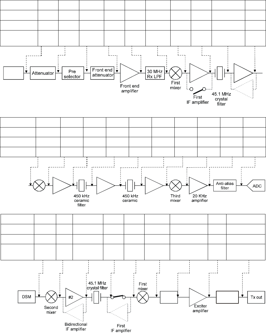
MM-E 2072-09333-00
2-31
2-4.10 LORD Module Test Point Data
The LORD module has several test points, which enable measurement of signal levels and frequencies
using a spectrum analyzer. Figure 2-16 provides a map of the available test points, and Figure 2-15
provides typical signal levels and frequencies at critical points (these test points are identified by a
larger type in Figure 2-16). These test points can be used for troubleshooting purposes.
Gain (dB) -3 -2.5 0 13 10 -6 12 -4 15 -
P (dBm) -95 -98 -100 -100 -86 -98 -104 -88±4 -97 -82
F (MHz) FIN FIN FIN FIN FIN FIN 45.1 45.1 45.1 45.1
Designation *1 *2 PS_OUT
AMP_1
AMP_2
Second
Mixer
AMP_4
AMP_3
XTAL_OUT
IF2_3
Bidirectional
IF amplifier
RX IN
Gain (dB) -6 22 -1.5 8 -1.5 13 0 28 0 -
P (dBm) -82 -88 -66 -67.5 -59.5 -61 -48 -48 -20 -20
F (MHz) 45.1 0.45 0.45 0.45 0.45 0.45 0.45 0.02 0.02 0.02
Designation
IF2_3 IF3_1 IF3_2 IF3_3 IF3_4 IF3_5 IF3_6 AF_2 AF_3 ADC_IN
Second
mixer
Second
IF amplifier
Second
IF amplifier
Second
IF amplifier
Gain (dB) -6 15 -4 0 -6 -6 25 -6
P (dBm) -25 -31 -15±4 -21 -27 -33 -6 -6 -12
F (MHz) 1.05 45.1 45.1 45.1 45.1 FOUT FOUT FOUT
FOUT
Designation
DSM_N
IF2_3
XTAL_OUT
AMP_3
AMP_4
Second
Mixer
EX_AMP_LPF
*3 EX_AMP_OUT
Attenuator
30 MHz
TX LPF
Figure 2-15. LORD Module, Typical Test Point Signal Frequencies and Levels
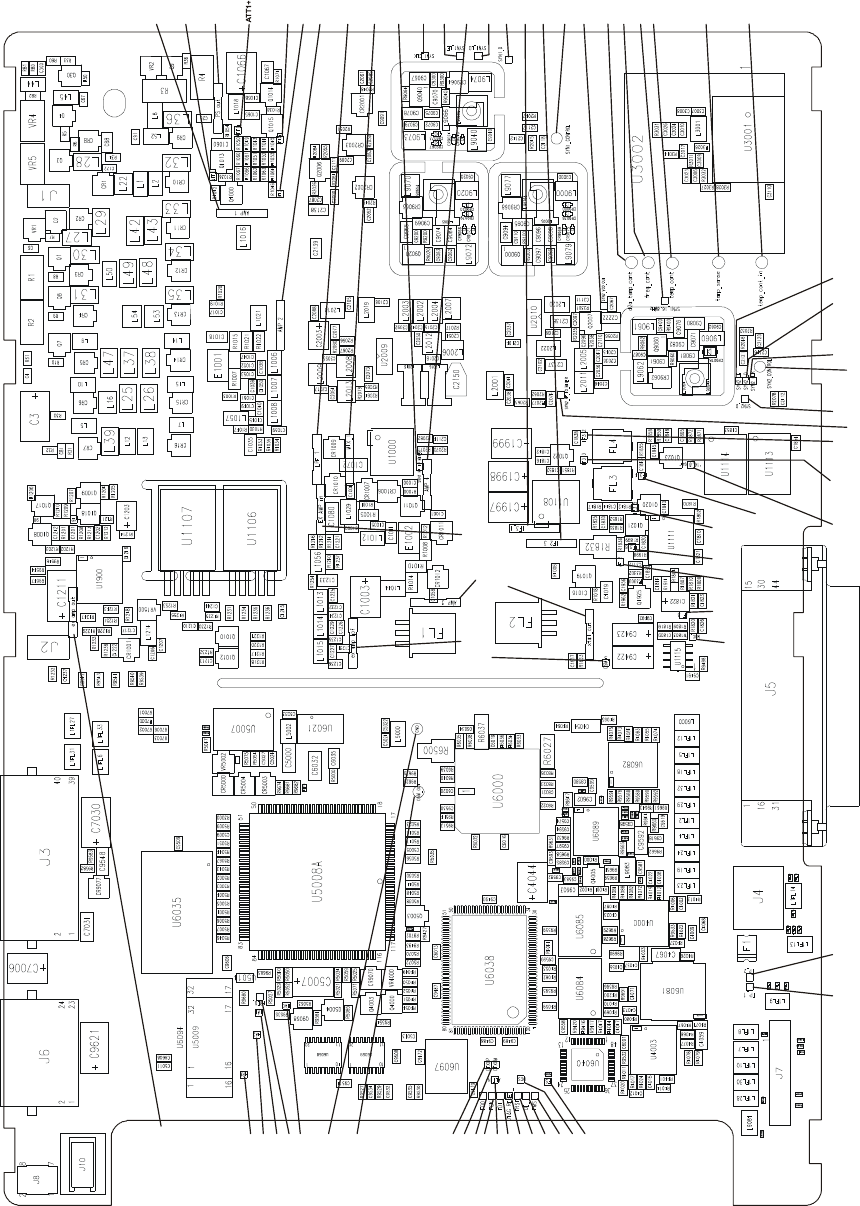
MM-E 2072-09333-00
2-32
S
Y
N
2
_
V
C
O
_
O
U
T
S
Y
N
2
_
R
F
_
T
O
_
M
I
X
E
R
S
Y
N
2
_
D
1
6
.
8
_
S
Q
R
I
F
3
_
5
I
F
3
_
6
A
F
_
2
A
F
_
3
A
D
C
_
I
N
I
F
3
_
4
I
F
3
_
2
I
F
3
_
3
S
Y
N
2
_
C
L
K
S
Y
N
2
_
C
O
N
T
R
O
L
S
Y
N
2
_
L
D
S
Y
N
2
_
L
E
S
Y
N
1
_
C
O
N
T
R
O
L
I
F
3
_
1
I
F
2
_
3
S
Y
N
1
_
D
S
Y
N
1
_
L
D
S
Y
N
1
_
L
E
A
M
P
4
S
Y
N
1
_
C
L
K
A
M
P
2
L
P
F
1
M
I
X
_
1
A
M
P
1
P
S
O
U
T
A
T
T
1
A
T
T
2
A
T
T
2
+
D
2
A
_
T
E
M
P
_
C
O
N
T
F
R
E
Q
_
C
O
N
T
T
E
M
P
_
C
O
N
T
T
E
M
P
_
S
E
N
S
E
T
E
M
P
_
C
O
N
T
_
I
N
S
Y
N
1
_
1
6
.
8
M
H
Z
S
Y
N
1
_
R
F
_
T
O
_
M
I
X
E
R
AMP_3
DSM_N
EX_AMP_LPF
EX_AMP_IN
EX_AMP_OUT
XTAL_OUT
R9701
DSM_OUT
GND
TD0
DTXCP
DTXCM
TCK
ALTIN
TD1
JTAG_RESET
TRST
DE_
TMS
DCSI
FS
TP_2TP_1
HRW
HA2
HA1
HA0
HREQ_
Figure 2-16. LORD Test Points Map
MM-E 2072-09333-00
2-33
2-5. HI POWER MODULE
The functional block diagram of the HI POWER module is shown in Figure 2-17. The HI POWER
module comprises the power amplifier subsystem, the harmonic filter circuits and their control
circuits, and the Micom-Z power supply subsystem.
2-5.1 Power Amplifier (PA)
2-5.1.1 ALC Attenuator
Refer to Figure A-2.B.
The RF_INPUT_TX signal received via connector P4 from the LORD module is connected to the
ALC attenuator, comprising R77 and the PIN diodes CR8, CR9.
The attenuation is controlled by the V_ALC voltage: a higher voltage increases the attenuation.
2-5.1.2 Power Amplification Chain
Refer to Figure A-2.B.
a. Predriver. The ALC attenuator output signal is amplified by the predriver stages Q5 and Q7.
The supply voltage to Q5 and Q7, VDD_PREAMP, is connected only in the transmit mode, by
a switch comprising Q10, Q12: the switch connects the SW_BATT line only when 9V appear
on the 9T line.
The bias voltage for Q5 and Q7 (3V nominal) is provided by the +3.3V linear regulator, U1, via
voltage dividers connected to their gates.
The bias voltage is present only when the PA_INHIBIT line is at a high level.
b. Driver. The predriver output, PRE_DRIVER, is amplified by a push-pull stage comprising Q3
and Q4. The bias voltages are provided by the +5V linear voltage regulator U6, via the
potentiometers R67, R73.
The bias voltage is present only when the BIAS_EN line is at a high level.
c. Power Amplifier. The driver output signal is amplified by a push-pull stage comprising Q6 and
Q11. The bias voltage is derived from the +3.3V provided by the linear regulator U11, via the
source follower stage, Q8: Q8 source voltage is determined by the collector voltage of Q2,
which can be adjusted by means of potentiometer R22.
The bias voltage is present only when the BIAS_EN line is at a high level, and both the +5V
and +10V voltages are present.
2-5.2 TX/RX Switch
Refer to Figure A-2.C.
The RF output of the power amplifier, PA_OUT, is connected to the TX/RX switch, the relay K1.
a. In the receive mode, K1 is not energized and connects the harmonic filter output to the
RX_TO_LORD line.
b. In the transmit mode, and also in the BIT mode, K1 is energized by the 9T and/or BIT lines, and
connects the PA_OUT line to the harmonic filter bank.
2-5.3 Harmonic Filter Bank
Refer to Figure A-2.C, Figure A-2.D.
The harmonic filter is used to attenuate the unwanted spurious and harmonics of the transmitted and
received signals. The direction of flow through the harmonic filter is determined by the TX/RX
switch, K1, as explained in para. 2-5.2.
The harmonic filter contains seven low pass filters. The filter corresponding to the operating frequency

MM-E 2072-09333-00
2-34
is inserted in the signal path by a pair of relays, controlled by the LORD module via the serial data line
SPI_DATA.
The relay control data is loaded into the serial/parallel converter U4 at the rate of the SPI_CLK clock
signal, and updates the U4 outputs when the SPI_SEL line rises to a high level. Each U4 output drives
one pair of relays, via Darlington stages in U3: at any time, only one U4 output assumes a high level,
causing the corresponding pair of relays to energize and insert a filter in the RF signal path.
The filter ranges and the corresponding relays are listed in Table 2-8.
Table
2-8. Harmonic Filter Frequency Ranges and Controlling Relays
Filter Frequency Range Relays
1 1.6 to 2.43 MHz K101, K102
2 2.43 to 3.7 MHz K201, K202
3 3.7 to 5.6 MHz K301, K302
4 5.6 to 8.5 MHz K401, K402
5 8.5 to 13 MHz K501, K502
6 13 to 19.8 MHz K601, K602
7 19.8 to 30 MHz K701, K702
2-5.4 Power Sensor
Refer to Figure A-2.C.
The forward/reflected power sensor, comprising T4 and the rectifiers CR6 and CR7, is inserted
between the filters and the antenna connector, J2.
During transmission, it generates two DC signals:
a. V_FWD_RADIO, proportional to the forward RF power delivered to the antenna
b. V_REV_RADIO, proportional to the RF power reflected from the antenna.
The signals are sent to both the ALC control circuits, and to the microcomputer system in the LORD
module, for controlling the transmit power as a function of the following parameters (see para. 2-5.5):
• VSWR value: if the VSWR increases above 2:1, the output power is gradually decreased, to
protect the radio from high reflected power.
• Harmonic filter insertion losses: if the harmonic filter insertion loss is too high, the output power
level is decreased.
2-5.5 ALC Circuits
Refer to Figure A-2.E.
a. Internal/External Power Amplifier Selector. Normally, Micom-Z uses its internal RF power
amplifier, and a low level is applied to Q807 via the EXT_AMP_EN line. The analog switches
in U12 then connect the V_FWD_RADIO and V_REV_RADIO lines to the ALC circuits.
b. Forward Power Control. The V_FWD_RADIO voltage passes through the peak detector (U5,
CR809) to the ALC error amplifier, U13. U13 compares the level with the ALC_REF_DAC
power reference received from the LORD module via the non-inverting buffer U15: a higher
V_FWD_RADIO level causes the output (pin 4) of U13 to assume a lower voltage, resulting in
a higher voltage at the emitter of Q23, which drives the V_ALC line.
This increases the attenuation of the ALC attenuator, tending to return the transmit power to its
normal level. The reverse action occurs when V_FWD_RADIO is less than normal.
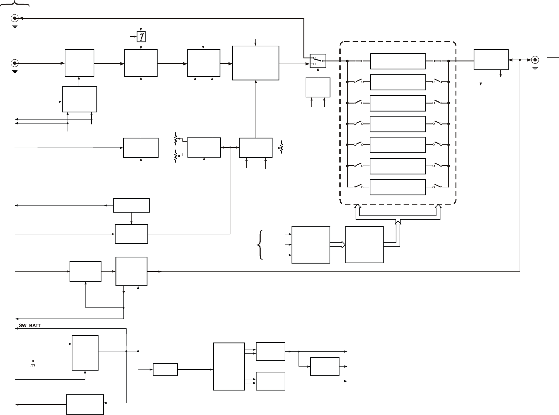
MM-E 2072-09333-00
ALC
Attenuator
CR8, CR9
VALC
ALC_REF_DAC
Predriver
Amplifier
Q5, Q7
Driver
Amplifier
Q3, Q4
Power Amplifier
Q6, Q11
PA Bias
Generator
Q2, Q8, U11
Driver Bias
Generator
U6
TX/RX
Switch
K1
P2
P4 RF_INPUT_TX
RX_OUT
To LORD
ALC Circuit
U5, U13, U14
Power Sensor
T4, CR6, CR7
Driver
Q801
V_REV_RADIO
V_REV_RADIO
PWR_AMP_BIAS
V_FWD_RADIO
J2
V_FWD_RADIO
PA_OUT
SW_BATT
9T
Temp Sensor
RT3, Q806, U9
Overheat
Protection
Q10
BIAS_EN
TEMP1
9T
Q10, Q12 SW_BATT SW_BATT
+5V +10VDC
9T BIT
10VDC
+10VDC
PA_INHIBIT R22
R67
R73
Predriver Bias
Generator
U1
To ANT
K101 K102
Harmonic Filter
K201 K202
K301 K302
K401 K402
K501 K502
K601 K602
K701 K702
Relay Control Signals
Band 1 (1.6 - 2.43 MHz)
Band 2 (2.43 - 3.7 MHz)
Band 5 (8.5 - 13 MHz)
Band 3 (3.7 - 5.6 MHz)
Band 6 (13 - 19.8 MHz)
Band 4 (5.6 - 8.5 MHz)
Band 7 (19.8 - 30 MHz)
Relay Drivers
U3
Serial/Parallel
Converter
U4
SPI_DATA
SPI_CLK
SPI_SEL
Tuner Current Limit
DC_PWR_IN
E1
+
_
E2
CH_CHANGE
BATT_CHECK
ATU DC
Switch
Q17, Q15,
Q802, Q803
Protection
Circuit
U22, U19
Battery Voltage
Monitor
U10, VR4
Dual
Switching
Regulator
U20
+10V
Regulator
Q13, U21
+5V
Regulator
Q1, U2
Filter
ON/OFF
Switch
and Surge
Protector
U23, Q14,
Q26
DC_PWR_EN
SW_BATT
SW_BATT_PS
+10VDC
+8VDC
+5VDC
+8V
Regulator
U16
V_TEMP_PA
From LORD
Figure 2-17. HI POWER Module, Functional Block Diagram
2-35/2-36
MM-E 2072-09333-00
2-37
c. Reverse Power Protection. The V_REV_RADIO voltage passes through the peak detector (U14,
CR811) to the reverse power comparator, U13: when the reverse power increases, the output
(pin 5) voltage decreases, resulting in a higher voltage at the emitter of Q23, which drives the
V_ALC line.
d. Overheat Protection. The thermistor RT3 causes the voltage on the V_TEMP_PA line
(monitored by U5008, located on the LORD module), to be proportional to the internal
temperature.
When the temperature is too high, the voltage on the V_TEMP_PA line exceeds the threshold of
the comparator U9, and the TEMP1 lines assumes a high level. This turns Q19 on, and turns off
the bias voltages via the BIAS_EN line.
2-5.6 Power Supply Subsystem
Refer to Figure A-2.F.
a. ON/OFF Switch and Surge Protector. The ON/OFF switch comprising the MOSFETs Q14,
Q26, connects the DC input voltage to the internal power supply line, SW BAT, only if the
GATE output of the surge stopper U23 provides a sufficiently high gate drive voltage. This
occurs only when the Micom-Z is turned on (provided the polarity of the input voltage is
correct: otherwise, U23 shut down input is pulled to ground even if the DC_PWR_EN line is
connected to ground by switching the Micom-Z ON).
Moreover, Q14 and Q26 will be turned off by U23 if the input voltage line, DC_PWR_IN, is
not within the allowed range.
When Q14 and Q26 are both ON, the input voltage is connected to the internal protected supply
voltage line, SW_BATT.
The SW_BATT line is monitored by U5008, located on the LORD module, via the battery
voltage monitor, U10.
b. Micom-Z Power Supply. The SW_BATT line is used to power the dual switching regulator,
U20.
One section of U20 drives the step-down converter that powers the +10V linear regulator, U21.
The linear regulator U16 uses the +10 VDC voltage to provide +8 VDC.
The other section of U20 drives the step-down converter that powers the +5 VDC linear
regulator, U2.
c. ATU DC Power Switch. The SW_BATT line can be connected to the DC_ANT_CPLR line by
the switch Q15.
To turn Q15 on, the LORD module provides a high level on the CH_CHANGE line.
The current flowing through Q15 is monitored by Q802: if the current is too high, Q803
saturates, and resets the latch U22. The resulting low level on the LATCH line turns Q15 off.
The TUNER_CURR_LIM line is also monitored by the LORD module.
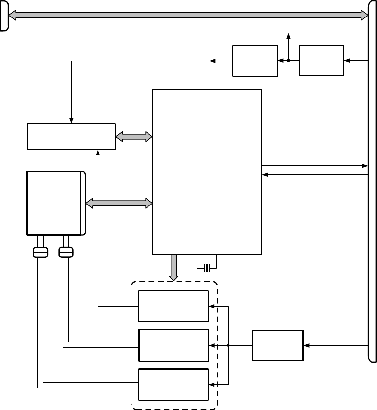
MM-E 2072-09333-00
2-38
2-6. CONTROL HEAD MODULE
Figure A-3 shows the schematic circuit diagram of the CONTROL HEAD module for both the
dash-mount and trunk-mount versions.
2-6.1 CONTROL HEAD Module for Dash-Mount Version
Figure 2-18 shows the functional block diagram of the CONTROL HEAD module used in the
Micom-Z dash-mount version.
2-6.1.1 Microcontroller
Refer to Figure A-3.B.
a. Microcontroller. The microcontroller, U1, is a 16-bit microcontroller with a 8 kB data RAM, a
128 kB flash memory that stores the application program, two A/D converters with 8
multiplexed inputs, two D/A converters, two UARTs and a large number of input and output
ports. Its internal clock oscillator uses the 7.3728 MHz crystal Y1 as a frequency reference.
b. Keypad Interface. The keypad (Figure A-3.C) is a 5×5 matrix of switches, with the row lines
connected to the 3V3_IF line via series resistors. The row and the column lines are connected to
ten of the I/O ports of U1, which can thus detect the pressing of each key, including the volume
control keys.
LCD
P6
J3 Microcontroller
U1
P2
P4
Panel
Keypad Lighting
Control
Q504, Q506
LCD Heater
Control
U7, Q1, Q3, Q501
LED Lighting
Control
Q502, Q503
DC/DC
Converter
U6, Q2
13V8DC
14V7
Y1
3V
Regulator
U5
To
LORD
3.3V
Regulator
U4
3V3
P3
Serial Control Channel
(UART 0)
3V0
Audio
Connector
5V0
Figure 2-18. CONTROL HEAD Module for Dash-Mount Version, Functional Block Diagram
MM-E 2072-09333-00
2-39
c. ON/OFF Control. The ON/OFF push-button, SW26, is normally open: when pressed to turn the
Micom-Z on, it connects ground to the ON_OFF_CONT line, which turns the power supply
subsystem on the HI POWER module on.
When Micom-Z operates, the microcontroller U1 can read the status of the switch via an
inverter in U3: when the switch is pressed again, the microcontroller is alerted to the turn-off
request, and keeps the ON_OFF_CONT line at a low level by turning Q507 on via the
POW_OFF_CPU line, until it completes its shut-down routine.
d. LCD Interface. The LCD interfaces with U1 via the CPU_D0 to CPU_D7 data bus.
e. Communication with LORD module. U1 communicates with the microcomputer subsystem on
the LORD module via a serial control channel, connected to the internal UART 0.
2-6.1.2 Auxiliary Power Supply
Refer to Figure A-3.E.
The 13V8DC supply line received via the LORD module is converted to 14.7V by the DC/DC
converter comprising the pulse-width modulation (PWM) controller U6, which drives the switching
MOSFET Q2.
The resulting pulses at the secondary of T1 are rectified by CR2, and filtered by C72, C79, C83 to
obtain the 14V7 auxiliary supply voltage line.
U6 starts operating only when a high level is applied by U1 on the VLED_HEAT_EN line, to turn Q7
on.
2-6.1.3 LCD Heater and Backlighting Control
a. LCD Backlighting. The 14V7 line can be connected by Q503 to the VLED_BL_LCD line by
applying a high level on the LCD_BL_EN line, thereby turning Q505 on.
b. LCD Heating. The 14V7 line can be connected by Q1 to the VHEAT_LCD line by applying a
high level on the LCD_HEAT_EN line. This causes Q3 to cut off. U7 output falls to a low level
to turn Q1 on, thereby connecting power to the VHEAT_LCD line.
The voltage on the VHEAT_LED line is regulated by U1, using feedback from the voltage
R158, R581, R159, R167, R536: by applying a high level on the LCD_HEAT_LEVEL line,
which turns Q501 on, the voltage can be reduced, thereby reducing the heating power to the
LCD.
2-6.1.4 Keypad Lighting
The 14V7 line can be connected by Q504 to the VLED_BL_KB line by applying a high level on the
KB_BL_EN line, thereby turning Q506 on.
2-6.1.5 MIC Connector Interface
The MIC connector, P6, includes the following interface lines:
a. Serial control channel (RXD, TXD), connected directly to the LORD side connector, P3.
b. PTT_MIC line, inverted by U3 and connected to connector P3.
c. MIC_IN line, connected to connector P3.
2-6.1.6 Power Supply Subsystem
The power for the CONTROL HEAD module is provided by the 5V0 line. The +5V supply voltage is
converted by the linear regulator U4 to +3.3V on the 3V3 line.
The linear regulator U3 provides +3V to the VDD_LCD_3V0 line.
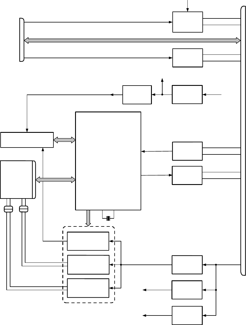
MM-E 2072-09333-00
2-40
2-6.2 CONTROL HEAD Module for Trunk-Mount Version
Figure 2-19 shows the functional block diagram of the CONTROL HEAD module used in the
Micom-Z trunk-mount version.
LCD
J3 Microcontroller
U1
P2
P4
Panel
Keypad Lighting
Control
Q504, Q506
LCD Heater
Control
U7, Q1, Q3, Q501
LED Lighting
Control
Q502, Q503
Voltage
Regulator
U6, Q2
13V8DC
14V7
Y1
3V
Regulator
U5
To INTERCONNECTION
3.3V
Regulator
U4
3V3
P501
3V0
Voltage
Regulator
U501
5V0
Voltage
Regulator
U502
8V0_AUDIO
Amplifier
U503 TX_AUDIO
RS-485
Line Driver
U506
PTT
RS-485
Line Receiver
U504
RS-485
Line Driver
U505
CH_RXD
CH_TXD
PTT_MIC
RX_UART0
TX_UART0
MIC_IN
Serial Control Channel (UART 0)
5V0
8V0_AUDIO
P6
Audio
Connector
Figure 2-19. CONTROL HEAD Module for Trunk-Mount Version, Functional Block Diagram
2-6.2.1 Microcontroller
Refer to Figure A-3.B, Figure A-3.C.
The microcontroller subsystem is similar to that used in the dash-mount version (para. 2-6.1.1). The
connection of the serial control channel to the LORD module (via the INTERCONNECTION module)
MM-E 2072-09333-00
2-41
is made via an RS-485 transceiver, comprising the line receiver U504 and the line driver U505 (refer
to Figure A-3.E).
2-6.2.2 Auxiliary Power Supply
Refer to Figure A-3.E.
The auxiliary power supply is similar to that of the dash-mount version (para. 2-6.1.2).
2-6.2.3 LCD Heater and Backlighting Control
The LCD heater and backlighting control circuits are similar to the dash-mount version (para. 2-6.1.3).
2-6.2.4 Keypad Lighting
The keypad lighting control circuits are similar to the dash-mount version (para. 2-6.1.4).
2-6.2.5 MIC Connector Interface
Refer to Figure A-3.F.
a. The MIC_IN signal is amplified and converted to a balanced signal (TX_AUDIO_P,
TX_AUDIO_N) by the amplifiers in U503, for transmission over the interconnection cable.
b. The PTT_MIC signal is converted to a RS-485 balanced signal by the RS-485 line driver U506.
2-6.2.6 Power Supply Subsystem
Refer to Figure A-3.D.
The power for the CONTROL HEAD module is provided via the 13V8DC line:
a. The linear regulator U501 converts the 13V8DC line to +5V on the 5V0_INT line.
b. The linear regulator U502 converts the 13V8DC line to +8V on the 8V0_AUDIO line. U503
derives a +4V voltage, AUDIO_BIOS, for the MIC IN audio amplifier.
c. The +5V supply voltage is converted by the linear regulator U4 to +3.3V on the 3V3 line.
d. The linear regulator U3 provides +3V to the VDD_LCD_3V0 line.
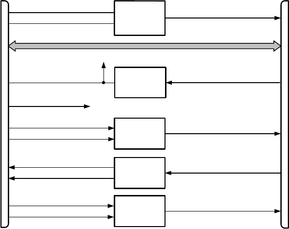
MM-E 2072-09333-00
2-42
2-7. INTERCONNECTION MODULE
Refer to Figure A-4.
Figure 2-20 shows the functional block diagram of the INTERCONNECTION module.
P2
Amplifier
U1
P1
TX_AUDIO
To
Control
Head
13V8_RADIO_TRUNK Voltage
Regulator
Q1, U2
To Internal Circuits
13V8_DC_RADIO
ON_OFF_CONT_PNL
Line
Receiver
U5
PTT
Line Driver
U4
Line
Receiver
U3
CH_RXD
CH_TXD
PTT_MIC
RX_UART0
TX_UART0
To
LORD
MIC_IN
Figure 2-20. INTERCONNECTION Module, Functional Block Diagram
a. The TX_AUDIO_P, TX_AUDIO_N balanced signal is converted to a single-ended signal,
MIC_IN, by the audio amplifier U1.
b. The RS-485 balanced PTT signal is converted to a single-ended signal, PTT_MIC, by the
RS-485 line receiver U5.
c. The RS-485 balanced CH_TXD signal is converted to a single-ended signal, TX_UART0, by
the RS-485 line receiver U3.
d. The RX_UART0 signal is converted to a RS-485 balanced signal, CH_TXD, by the RS-485 line
driver U4.
e. The 13V8_DC_RADIO supply voltage received from the LORD module is connected to the
voltage regulator built around U2 and Q1.
Q1 connects the supply voltage to the 13V8_RADIO_TRUNK line supply voltage, which
powers the control head assembly through the interconnection cable.
In addition, the 13V8_RADIO_TRUNK line supply voltage is used to provide power to the
amplifier U1. Another amplifier in U1 provides the AUDIO_BIAS reference voltage for the
audio amplifier.
2-8. FAN CONTROL MODULE
Refer to Figure A-5.
The cooling tray includes the FAN CONTROL module. This module provides the connections
between the radio side connector, J2, and the user’s side connector, J3. In addition, it includes a
voltage regulator comprising U1 and Q2, which provides +12VDC to the fan installed in the tray. The
voltage regulator starts providing the voltage when a high level is applied on the DSO/FAN_ON_OFF
line: this turns Q1 on, and enables U1.

MM-E 2072-09333-00
3-1
Chapter 3
MAINTENANCE
3-1. SCOPE
This Chapter provides maintenance instructions for Micom-Z.
The information presented in this Chapter covers testing, troubleshooting procedures, and repair
instructions. Use Appendix B to identify components and find other data needed for troubleshooting
and repair.
3-2. HANDLING PRECAUTIONS DURING MAINTENANCE
Equipment maintenance is performed in accordance with standard practice. During equipment
maintenance, observe the following precautions:
a. To preserve equipment reliability, the equipment should be serviced only in a protected, clean
environment.
b. Electronic components, in particular CMOS and RF devices, are susceptible to damage by
electrostatic discharge (ESD). Electrostatic charge is created by friction between different
bodies, including the human body, especially under dry conditions. Damage can be latent,
resulting in failures occurring weeks or months later. Therefore, special precautions must be
taken to prevent device damage during disassembly, troubleshooting, and repair. To prevent
damage, use the following precautions:
• Eliminate static generators (plastics, styrofoam, etc.) in the work area.
• Remove nylon or double-knit polyester jackets, roll up long sleeves, and remove or tie back
loose hanging neckties.
• Disconnect all power from the unit before starting repair activities.
• Use a static safeguarded workstation, which can be accomplished through the use of an anti-
static kit, which typically includes a wrist strap, two ground cords, a static-control table mat,
and a static-control floor mat.
When these items are not readily available, observing the following techniques will
minimize chance of damage:
If a static-sensitive device is to be temporarily set down, use a conductive surface for
placement of the device.
Make skin contact with a conductive work surface first and maintain this contact when
the device is set down or picked up.
c. Keep any module (good or defective) in the original packaging, even when the module is placed
on the workbench.
d. Handle modules carefully; do not drop modules, and avoid piling them up, because the exposed
components may be damaged by physical stress and shock. Always use the original packaging
of the module and do not use alternative packaging, unless the original one is damaged or lost.
The original packaging is designed to absorb mechanical shocks and to protect the equipment
against electrostatic discharge.
e. Hold a module by its sides, and avoid touching its connectors or electronic components installed
on the module. This practice will prevent mechanical damage, oily deposits on contacts and
damage due to electrostatic discharge.

MM-E 2072-09333-00
3-2
f. Micom-Z modules make extensive use of surface-mounted (SMT) components and
miniaturization, therefore personnel involved in troubleshooting and repair must be thoroughly
familiar with the applicable workmanship procedures. No special tools are needed for repair,
except for a standard technician’s toolbox and a soldering/desoldering station with an
appropriate set of tips, considering the component types used in the module (in particular multi-
lead and SMT components). Use standard workmanship practice for repair and component
replacement procedures:
• Pay special attention to avoid overheating or damage to adjacent components. Use only a
soldering tool with a temperature-controlled tip, and minimize heating time.
• Pay attention to the orientation of polarized components.
• During soldering of RF transistors, use minimum solder and make sure that the solder does
not flow to other areas.
Clean the module after any repair, and thoroughly remove any remaining foreign matter, in
particular solder remnants. Inspect visually after repairs are completed.
g. Whenever a cover or a PCB is fastened by multiple screws, first insert all the screws and tighten
them by hand, and then use a screwdriver, to tighten completely the screws. Tighten the screws
alternately, starting with the screws at the opposite ends of one diagonal, then those at the ends
of the other diagonal. Do not tighten one screw completely and then the others: take up one turn
at a time for each screw, sequentially, in the order described.
Avoid exerting excessive torque when tightening screws. Table 3-1 provides standard tightening
torques for screws (the allowed torque tolerance is ±10%).
Table 3-1. Tightening Torques for Screws
Screw Size Thread Forming
Metallic Surface
Threaded Metallic
Surface
Plastic
Surface
Metric System Screws
M3 10 kgf/cm 10 kgf/cm 6 kgf/cm
M4 15 kgf/cm 15 kgf/cm 7 kgf/cm
M5, M6 22 kgf/cm 18 kgf/cm 8 kgf/cm
American System Screws
4-40 10 kgf/cm 7 kgf/cm 6 kgf/cm
6-32 15 kgf/cm 15 kgf/cm 7 kgf/cm
8-32, 10-32 22 kgf/cm 18 kgf/cm 8 kgf/cm

MM-E 2072-09333-00
3-3
3-3. CLEANING
WARNING
Prolonged breathing of cleaning compounds may be dangerous; make
certain that adequate ventilation is provided. Do not use near a flame.
Avoid contact with the skin. If contact with skin is made, immediately
wash off with water.
Before performing any maintenance actions, clean the equipment in accordance with the following
procedure:
a. Inspect the exterior of the unit. The surfaces should be clean and free of dirt, grease and other
contaminants.
b. Remove dust and other loose dirt with a soft clean cloth. If dirt is difficult to remove, dampen
the cloth with water; mild soap may be used for more effective cleaning.
c. Remove grease, fungus and ground-in dirt from the cases: use a lightly dampened cloth (not
wet) with an approved cleaning compound.
d. Remove dirt from connectors with a brush.
3-4. TESTING
3-4.1 Micom-Z Testing
a. Full Performance Tests. The Micom-Z radio sets are tested by means of an automatic test
station, Mfg. Cat. No. 2089-08892-00. Refer to the test station documentation for detailed
procedures.
b. Periodic Alignment and Calibration. The transmit power and frequency accuracy of Micom-Z
radio can be calibrated using the PC-based Radio Service Software (RSS), option G424
(FVN4841). Refer to the RSS User Guide, Publication 6886867J01, for detailed instructions.
3-4.2 Module Testing and Alignment
The following automatic test stations are used to test and align Micom-Z modules:
• LORD module – use test station Mfg. Cat. No. 2072-08001-00.
• HI POWER module - use test station Mfg. Cat. No. 2072-08503-00.
Refer to the test station documentation for detailed procedures.
MM-E 2072-09333-00
3-4
3-5. TROUBLESHOOTING
The purpose of the troubleshooting procedures is to return a defective Micom-Z unit to normal service
as soon as possible, by isolating the malfunction to a replaceable subassembly or module, and then
repairing the subassembly or module.
3-5.1 Overview of Troubleshooting Procedures
In case a malfunction is detected (either during field operation, or during testing), perform the
following steps in the order presented below, until the problem is isolated and corrected:
1. Refer to the troubleshooting instructions given in para. 3-7.2 of the Micom-Z Operator Manual,
which provides instructions for isolating the fault to a replaceable subassembly or module.
These instructions include preliminary troubleshooting, followed by the use of the BITE
function in accordance with para. 3-7.2 of the Micom-Z Operator Manual. After collecting the
error codes, refer to para. 3-5.2 for their interpretation.
2. If the problem is detected during testing, collect and analyze the results of the electrical test
procedures, and then refer to para. 3-5.4 for quick troubleshooting instructions. If the problem
cannot be corrected using the instructions in para. 3-5.4, refer to para. 3-5.5 for systematic
troubleshooting procedures.
Refer to para. 3-6 for Micom-Z disassembly, module replacement, and assembly procedures.
3. After identifying the defective subassembly or module, refer to para. 3-5.5 for module
troubleshooting instructions.
Remember that visual inspection may often detect faults without testing or making measurements.
Therefore, after opening the Micom-Z case, perform a thorough visual inspection and inspect its
wiring and module assemblies for physical damage. In particular, check for any external signs of
damaged components and/or damaged printed circuit boards. The possibility of intermittent faults
should not be overlooked. To reveal such defects, check the wiring, the coaxial cables, and the various
plugs and jacks of the modules. If the inspection reveals damage, replace the suspected part in
accordance with the applicable procedure of para. 3-6 before starting any other troubleshooting
procedures.
After completing the troubleshooting procedure and the associated repair tasks, repeat the full set of
performance checks listed in para. 3-4 to verify that the equipment has been returned to fully
operational condition.
NOTE
After replacing the LORD and/or the HI POWER module, it is
necessary to calibrate the RF transmit power using the RSS.
3-5.2 BIT Error Codes
Table 3-2 explains the meaning of the error codes generated by the BIT function, and lists their most
probable cause.
Table 3-2. BIT Error Codes
Error Code
Meaning Probable Cause
00 O.K. – no errors
01 DSP boot checksum fail (during
download)
LORD board problem
02 DSP PLL unlock LORD board problem
03 DSP external RAM memory LORD board problem
04 Not applicable
05 DSP internal RAM memory LORD board problem

MM-E 2072-09333-00
3-5
Table 3-2. BIT Error Codes (Cont’d)
Error Code
Meaning Probable Cause
06 Not applicable
07 Not applicable
08 HC16 flash memory checksum LORD board problem
09 HC16 RAM memory LORD board problem
10 No 16.8 MHz clock Check for good power cable connection.
Possible LORD board problem
11 Battery low Weak internal battery: replace battery to correct
problem
12 Control head wake-up Control head problems
13 Control head is not responding Control head problems
14 Radio not programmed Problem experienced during programming.
Program radio (connect MRC or RSS at 1200 bps)
15 Database fail ALE scanned channels do not match the channels
programmed by means of the MRC or RSS
16 VCO 1 first injection LORD board problem
17 VCO 2 first injection LORD board problem
18 VCO 3 first injection LORD board problem
19 VCO second injection LORD board problem
20 Synthesizer unlock LORD board problem
21 Receiver failure LORD board problem
22 Preselector range 1 LORD board problem
23 Preselector range 2 LORD board problem
24 Preselector range 3 LORD board problem
25 Preselector range 4 LORD board problem
26 Preselector range 5 LORD board problem
27 Preselector range 6 LORD board problem
28 Preselector range 7 LORD board problem
29 Preselector range 8 LORD board problem
30 Exciter test HI POWER board problem
31 Antenna mismatch Problem with antenna: check antenna and its
connections. If problem persists, it is a HI POWER
board problem
32 Harmonic filter range 1 HI POWER board problem
33 Harmonic filter range 2 HI POWER board problem
34 Harmonic filter range 3 HI POWER board problem
35 Harmonic filter range 4 HI POWER board problem
36 Harmonic filter range 5 HI POWER board problem
37 Harmonic filter range 6 HI POWER board problem
38 Harmonic filter range 7 HI POWER board problem
39 Power amplifier fail HI POWER board problem

MM-E 2072-09333-00
3-6
3-5.3 Troubleshooting Procedure
The purpose of the troubleshooting procedure presented in this Section is to rapidly return a defective
Micom-Z to service by replacing suspected modules:
a. Identify the closest description of the problem under “Problem Symptom” in Table 3-3.
b. Perform the required corrective actions listed under “Corrective Actions” in the table in the
order of appearance, until the problem is corrected.
If the replacement of an item (module, PCB, assembly) during the troubleshooting procedure
does not correct the problem, reinstall the original item before continuing to the next step.
c. After a trouble is isolated, follow the repair instructions given in para. 3-6.
d. After correcting the trouble and repairing the unit, repeat the performance checks in accordance
with para. 3-4.
Table 3-3. Troubleshooting Procedure
No. Problem Symptom Suspected Module(s)
1 Transceiver cannot be turned on • LORD module
• HI POWER module
• CONTROL HEAD module
• INTERCONNECTION module (trunk version only)
2 No receive audio • LORD module
• CONTROL HEAD module
• INTERCONNECTION module (trunk version only)
Check also the flat cables and the coaxial cables
connections
3 No RF transmit power but transceiver
switches to the transmit mode
• LORD module
• HI POWER module
• CONTROL HEAD module
• INTERCONNECTION module (trunk version only)
4 Low RF transmit power First try to calibrate the RF transmit power using the
RSS.
• LORD module
• HI POWER module
• TUNER module
5 Transceiver cannot be switched to
transmit mode by pressing the
microphone PTT
• LORD module
• CONTROL HEAD module
• INTERCONNECTION module (trunk version only)
• Microphone
6 No LCD backlight CONTROL HEAD module
7 Blank LCD screen • LORD module
• CONTROL HEAD module
8 LCD displays jumbled characters • CONTROL HEAD module
• LCD
9 POWER LATCH message appears • HI POWER module (harmonic filter)
• LORD module

MM-E 2072-09333-00
3-7
Table 3-3. Troubleshooting Procedure (Cont’d)
No. Problem Symptom Suspected Module(s)
10 Distorted audio receive signal • LORD module
• CONTROL HEAD module
• Speaker
11 Excessive current consumption in
receive, or standby mode
• LORD module
• HI POWER module
• INTERCONNECTION module (trunk version only)
12 Excessive current consumption in
transmit mode
• HI POWER module
• Transmitter calibration
13 Low audio receive signal • LORD module
• HI POWER module
14 Low modulation of transmit signal • Microphone problem
• LORD module
• HI POWER module
15 Excessive distortion of audio receive
signal
LORD module
16 Transceiver enters the transmit mode,
and cannot be returned to the receive
mode
• LORD module
• CONTROL HEAD module
17 NO CLOCK message appears LORD module
18 Transceiver cannot be switched to
transmit mode by the voice PTT line in
the ACCESSORY connector
LORD module
19 Transceiver cannot be switched to
transmit mode by the data PTT line in
the ACCESSORY connector
LORD module
20 Transceiver cannot be switched to
transmit mode by the CW PTT (Morse)
line in the ACCESSORY connector
LORD module
21 LORD flash memory cannot be updated
LORD module
22 The icons related to the installed
options are not displayed
LORD module
23 SYNT FAIL message appears LORD module
24 Keypad does not operate normally, or
no response to key pressing
• CONTROL HEAD module
• Keypad
• INTERCONNECTION module (trunk version only)
25 GPS receiver cannot provide position fix
• LORD module
• GPS receiver
• Defective GPS antenna
• GPS antenna cable
26 No fan control command (cooling tray
OK)
LORD module
27 No output supply voltage for external
devices in the ACCESSORY connector
LORD module

MM-E 2072-09333-00
3-8
Table 3-3. Troubleshooting Procedure (Cont’d)
No. Problem Symptom Suspected Module(s)
28 No receive output signals for external
devices in the ACCESSORY connector
LORD module
29 No 13.8 VDC output for ATU in ANT
connector
• HI POWER module
• Tuner option not selected
30 MRC or RSS cannot communicate with
the transceiver via the ACCESSORY
connector
• LORD module
• CONTROL HEAD module
31 MRC or RSS cannot communicate with
the transceiver via the front panel MIC
connector
• LORD module
• CONTROL HEAD module
• INTERCONNECTION module (trunk version only)
32 No front and rear RSS communication LORD module
33 Excessive harmonic levels • HI POWER module
• LORD module
34 Transceiver does not return to last
operating state after being turned off
• Internal battery
• LORD module
35 Transceiver remains in the power-up
self-test state
LORD module
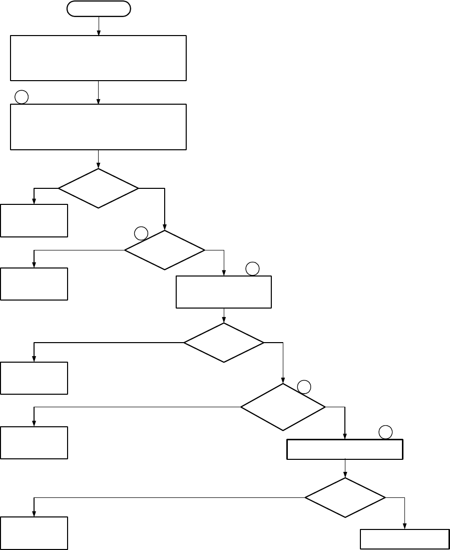
MM-E 2072-09333-00
3-9
3-5.4 Micom-Z Troubleshooting Charts
1. Perform the checks presented in Figure 3-1.
2. If a problem is detected at a checkout step of Figure 3-1, refer to the troubleshooting chart
identified next to the corresponding step, and then perform the troubleshooting activities listed
in the chart until the problem is corrected.
3. After correcting the problem, repeat the checkout procedure in accordance with Figure 3-1.
Perform visual inspection of equipment. Ensure
there is no physical damage.
If damage is found, repair or replace damaged
components before proceeding with checkout
No
Proceed to
troubleshooting
chart 1
Connect power cable to the power connector
and a wattmeter and dummy load to the ANT
connector. Attempt to turn on
Start
Radio
powered on?
Yes
Normal display? YesNo
1
2
Connect a microphone to
the mic jack. Key the mic
and whistle into it
3
Radio keyed? Yes
No
Transmit power
present?
4
Yes
Run the automatic BIT routine
Any errors
displayed?
5
No
Continue to checkout
step 6
Proceed to
troubleshooting
chart 2
Proceed to
troubleshooting
chart 3
Proceed to
troubleshooting
chart 4
No
Proceed to
Table 3-2
Yes
Figure 3-1.A. MICOM-Z Checkout Chart (Sheet 1 of 2)
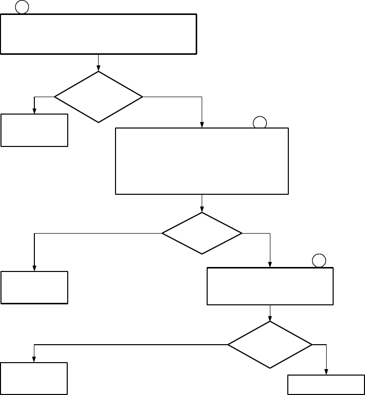
MM-E 2072-09333-00
3-10
No
Proceed to
troubleshooting
chart 5
Turn radio on and adjust the volume to midrange.
Press the SQ key to alternate between squelch on and
squelch off
Static heard
in the speaker
when squelch
is off?
Yes
6
7
Select USB mode and connect a signal
generator to the ANT connector. Inject -100 dBm
signal at the radios (operating frequency +1 kHz)
into the radio. Turn on the squelch and vary the
input frequency in a range of ± 500 Hz.
The radio should break squelch and audio
should be heard in the speaker
Squelch
operates correctly? YesNo
4
Yes
Checkout complete
8
Proceed to
troubleshooting
chart 6
Proceed to
troubleshooting
chart 7
No
Perform oscillator calibration and
power output calibration (refer to
RSS user's guide)
Any problems?
Figure 3-1.B. MICOM-Z Checkout Chart (Sheet 2 of 2)
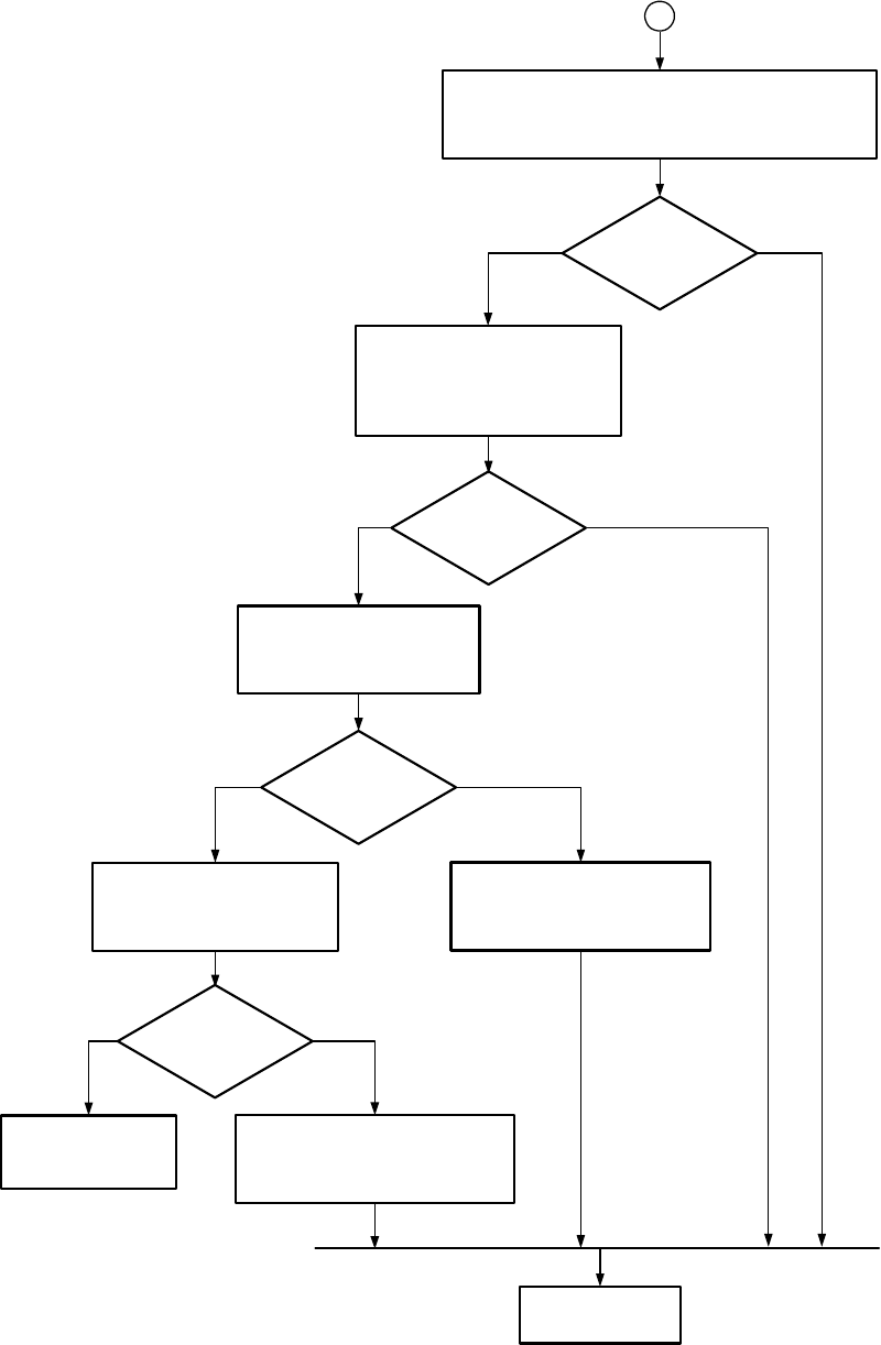
MM-E 2072-09333-00
3-11
No
Open radio and do a visual
inspection of the boards. If
visible damage is found, correct
by replacing or repairing
appropriate part
Ensure the power supply is on and provides 13.8 VDC
to the radio. Check inline fuse: replace if necessary
Radio
powered on?
Yes
1
Radio
powered on? Yes
No
Using a DC voltmeter, check
for 13.8V at J3 pin 13 and J6
pin 11 on the LORD module
13.8 VDC
present?
No
Verify the condition of the flat
cable from the LORD module
to the HI POWER module
using an ohmmeter
Cable good?
No
Replace cable and
proceed to step 1 of
checkout
Problem in control head.
Replace or repair as necessary
Yes
Yes
Problem is in HI POWER module.
Replace or repair as necessary
From Checkout Step
Proceed to step 1
of checkout
Figure 3-2. MICOM-Z Troubleshooting Chart 1
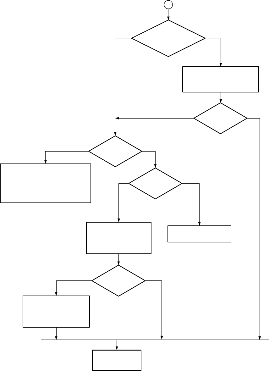
MM-E 2072-09333-00
3-12
No
Verify the condition of the flat
cable from the LORD module to
the front panel CONTROL HEAD
module using an ohmmeter
Yes
2
Pop sound heard
in speaker when the power
switch is turned on?
Cable good?
Blank display?
Yes No
No
Any error
displayed?
Yes
Proceed to troubleshooting
chart 8
Verify the condition of the
flat cable from the LORD
module to the front panel
CONTROL HEAD module
using an ohmmeter
No
Cable good? No
Yes
Problem is with the
CONTROL HEAD board.
Replace or repair as
necessary
The firmware was not loaded correctly
or an incorrect version was loaded.
Load the correct firmware version.
If loading the firmware fixes the
problem, proceed to step 2 of the
checkout. If the problem persists,
replace the LORD module
Yes
From Checkout Step
Replace cable and
proceed to step 2 of
the checkout
Figure 3-3. MICOM-Z Troubleshooting Chart 2
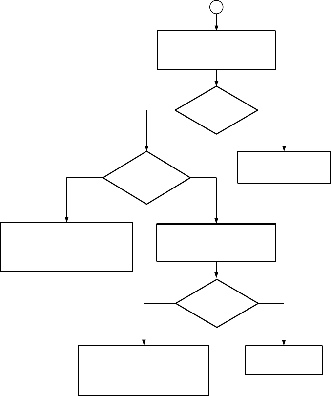
MM-E 2072-09333-00
3-13
No Yes
3
Radio keyed?
Connect J5
pin 8 to ground.
Radio keyed?
Yes
No
Problem found. Replace
microphone and proceed
to step 3 of checkout
No
Yes
Replace cable and
proceed to step 3 of
the checkout
Problem is with the CONTROL HEAD
module. Replace or repair as
necessary. Proceed to step 3 of the
checkout
No
Problem is with the LORD module.
Replace or repair as necessary.
Proceed to step 3 of the checkout
Possibly a bad microphone: try a
different microphone and key it
again, or connect pin 6 to ground
on the mic jack
Verify the condition of the flat
cable from the LORD module to
the front panel CONTROL HEAD
module using an ohmmeter
Cable good?
From Checkout Step
Figure 3-4. MICOM-Z Troubleshooting Chart 3
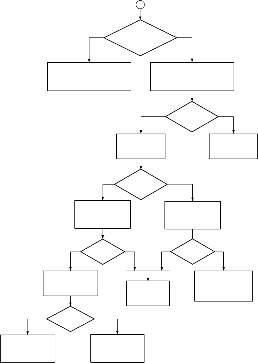
MM-E 2072-09333-00
3-14
No
Possibly a bad microphone, try a
different microphone and key/whistle
again, or connect 0 dBm audio to
pin 5 on the mic jack. Key the radio
by shorting J5 pin 8 to ground
Yes
4
PW Latch error
displayed on the screen
when whistling?
TX power
present
YesNo
Problem found.
Replace microphone
and proceed to
step 4 of checkout
Problem is on the HI POWER module.
Replace or repair as necessary.
Proceed to step 4 of the checkout
Connect a 0 dBm
audio signal to J5
pins 6 & 7 and key
the radio
TX power
present
YesNo
Verify the condition of
the RF cables from the
LORD module to the HI
POWER module using
an ohmmeter
Verify the condition of
the flat cable from the
LORD module to the HI
POWER module using
an ohmmeter
Cables good?
Cables good?
Yes
Problem is with the
CONTROL HEAD module.
Replace or repair as
necessary. Proceed to
step 4 of the checkout
Replace cable and
proceed to step 4
of the checkout
No
NoYes
Key the radio, whistle
and check J3 pin 11 for
AC voltage going to the
HI POWER module
Voltage present?
Problem is with the
LORD module. Replace
or repair as necessary.
Proceed to step 4 of
the checkout
Problem is on the
HI POWER module.
Replace or repair as
necessary. Proceed to
step 4 of the checkout
No
Yes
From Checkout Step
Figure 3-5. MICOM-Z Troubleshooting Chart 4
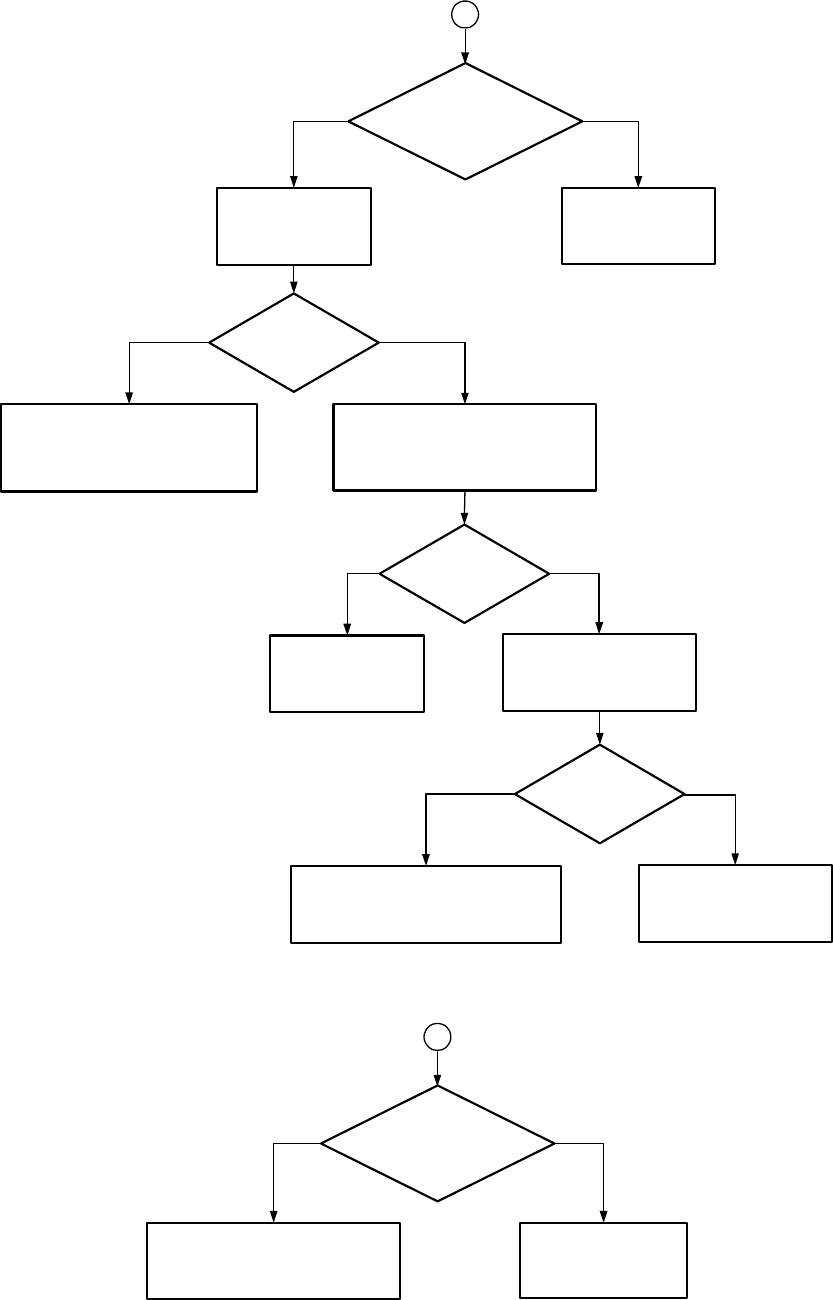
MM-E 2072-09333-00
3-15
No
Turn up the volume
and proceed to
step 6 of checkout
Yes
6
Check that
the volume is at
midrange or beyond
Voltage present? Yes
No
Using an AC
voltmeter, check for
audio voltage on J5
pins 1 and 3
Problem is with the LORD module.
Replace or repair as necessary.
Proceed to step 6 of the checkout
Verify the condition of the
flat cable from the LORD module to
the front panel CONTROL HEAD
module using an ohmmeter
Cable good?
Replace cable and
proceed to step 6
of checkout
No Yes
Check for audio at the
speaker connection on
the front panel connector
Audio present?
Replace defective speaker
and proceed to step 6 of
checkout
Yes
Problem is in the CONTROL HEAD
module. Replace or repair as
necessary. Proceed to step 6 of the
checkout
No
From Checkout Step
Figure 3-6. MICOM-Z Troubleshooting Chart 5
No
Turn up the volume
and proceed to step 7
of checkout
Yes
7
Check that
the volume is at
midrange or beyond
Problem is with the LORD module.
Replace or repair as necessary.
Proceed to step 7 of the checkout
From Checkout Step
Figure 3-7. MICOM-Z Troubleshooting Chart 6
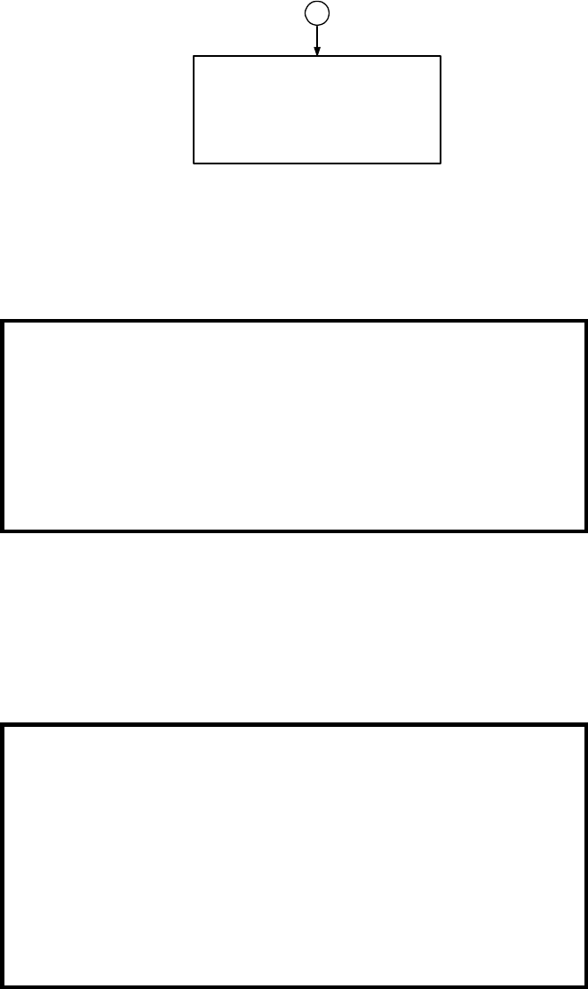
MM-E 2072-09333-00
3-16
8
If you are following the instructions in
the RSS Owner's Guide, and the
oscillator or power output will not
adjust, the problem is in the LORD
module.
Replace or repair as necessary.
Proceed to step 8 of the checkout
From Checkout Step
Figure 3-8. MICOM-Z Troubleshooting Chart 7
3-5.5 Module Troubleshooting Procedures
WARNING
To prevent permanent damage to printed circuit boards, the
following troubleshooting procedures must be performed only by
qualified, authorized personnel, familiar with the theory of
operation of the Micom-Z circuits, and trained in the maintenance
of electronic circuits.
Refer to para. 3-2 for safety precautions and component and
module handling and repair procedures.
Use the following charts, in conjunction with the relevant schematic circuit diagrams given in
Appendix A, to troubleshoot a module down to the component level.
• Refer to Figure 3-9 for systematic troubleshooting of the receive path circuits.
• Refer to Figure 3-10 for systematic troubleshooting of the transmit path circuits.
Use Appendix B for logistic data on individual components.
NOTE
After replacing the LORD and/or the HI POWER module, it is
necessary to calibrate the RF transmit power using the RSS.
The required RF power values are as follows:
1. TUNE – 7W
2. LOW – 25W
3. MED – 60W
4. HIGH – 100W
5. MAX – 125W.
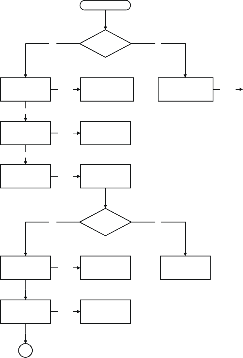
MM-E 2072-09333-00
3-17
Start
Check harmonic filter
range and its control
lines
Is any sound
heard in the
speaker?
Check the harmonic
filter range switching
Check from CONTROL
HEAD board to speaker
NoYes
Problem
found
Problem
found
Check path from
LORD RF input to
speaker output
Ranges OK
Reception possible
Check coax cables
Problem
found
Check LORD board
Problem
found
Check synthesizer
Is the input
signal to the
first mixer OK?
Check first
local oscillator
Check front-end
preselector
No
Yes
Problem
found
Check first mixer
Check 45.1 MHz
signal (IF filter)
Problem
found
A
Check coax from
HI POWER to LORD
Figure 3-9.A. Receiver Troubleshooting Flowchart (Sheet 1 of 2)
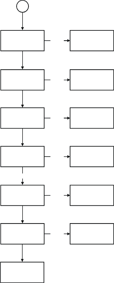
MM-E 2072-09333-00
3-18
A
Check synthesizer
Check second
local oscillator
Problem
found
Check second mixer
Check 450 kHz
signal (IF filter)
Problem
found
Check 450 kHz
ceramic filter
Check 20 kHz signal
Problem
found
Check A/D
DC voltage
Check A/D
converter
Problem
found
Check VCC
Check DSP output
signal
Reception possible
Problem
found
Check A
+
(13.8 V)
Check audio amplifier
Problem
found
Check flat cable to
CONTROL HEAD
Figure 3-9.B. Receiver Troubleshooting Flowchart (Sheet 2 of 2)
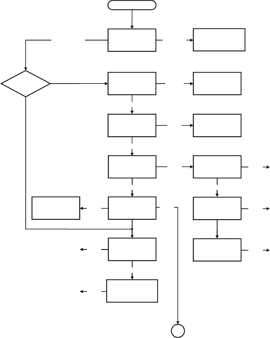
MM-E 2072-09333-00
3-19
Start
Transmit to a
dummy load
Antenna and/or
antenna tuner problem
A
Transmission
possible
Problem persists
Is transmission
in AME mode
posible?
Check the harmonic
filter ranges
No
Check the harmonic
filter and/or
its control lines
Problem in
one range
Problem in all ranges
Check the 9T, 9R, PA
DISABLE lines
Check the PTT path
from the
mic connector
to the LORD board
Problem
found
No problem found
Check from HI
POWER module to
antenna
Check from the mic
audio input to DSM
output
Problem
persists
Transmission possible
Check from the mic
audio input to
CONTROL HEAD
module output
Yes
Problem
found
Problem
found
Check the flat cable
between the
CONTROL HEAD and
the LORD module
Problem persists
Problem
found
Problem
persists
Check DSM & DSP
Check PA power
transistors
Problem
found
Check PA
Problem
found
Transistors OK
Check the HI POWER
as a separate unit
Problem
found
Figure 3-10.A. Transmitter Troubleshooting Flowchart (Sheet 1 of 2)
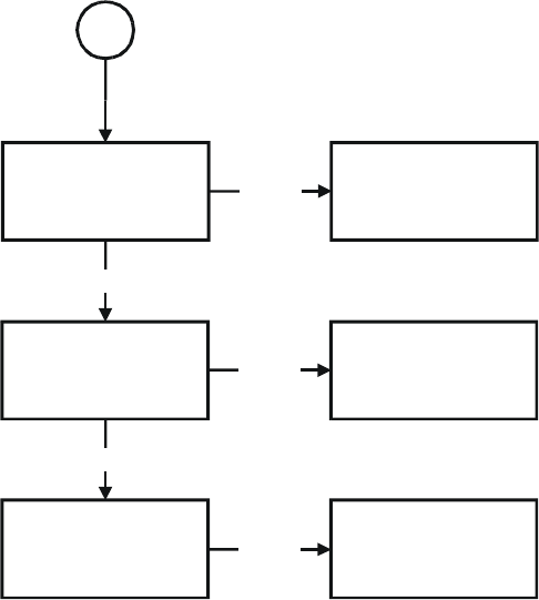
MM-E 2072-09333-00
3-20
A
Check second mixer
output
(45.1 MHz)
Problem
found
Check second
synthesizer
Problem persists
Check first mixer
output
(the frequency of the
working channel)
Problem
found
Check first
synthesizer
Problem persists
Check LORD module
output to HI POWER
module input
Problem
found
Check coax cable
Figure 3-10.B. Transmitter Troubleshooting Flowchart (Sheet 2 of 2)
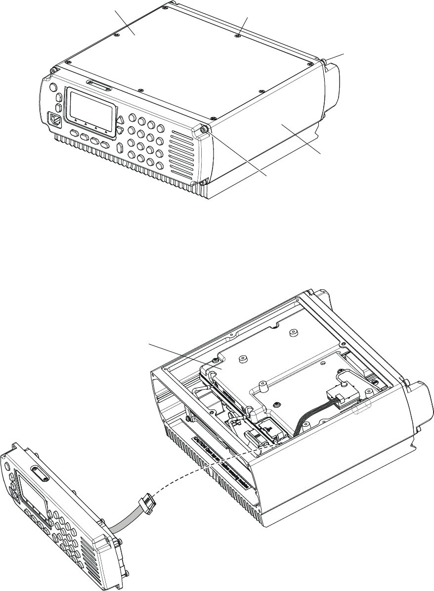
MM-E 2072-09333-00
3-21
3-6. MICOM-Z REPAIR PROCEDURES
3-6.1 Micom-Z Dash-Mount Version Repair
3-6.1.1 Gaining Access to Modules
1. Refer to Figure 3-11: release the 8 screws fastening the top cover, and then remove the top
cover.
Top Cover
Top Cover
Fastening Screws
(8 places)
Rear Panel
Fastening Screws
(4 places)
Front Panel
Fastening Screws
(4 places)
Body Assembly
Figure 3-11. Gaining Access to Modules
2. Release the four screws fastening the front panel to the body assembly. Keep screws and
washers for reuse.
3. Carefully separate the front panel, and then disconnect the flat cable connecting the front panel
to the LORD connector. Figure 3-12 shows the front panel after being removed.
LORD
Module
Flat Cable
to LORD
Figure 3-12. Micom-Z with Front Panel Removed
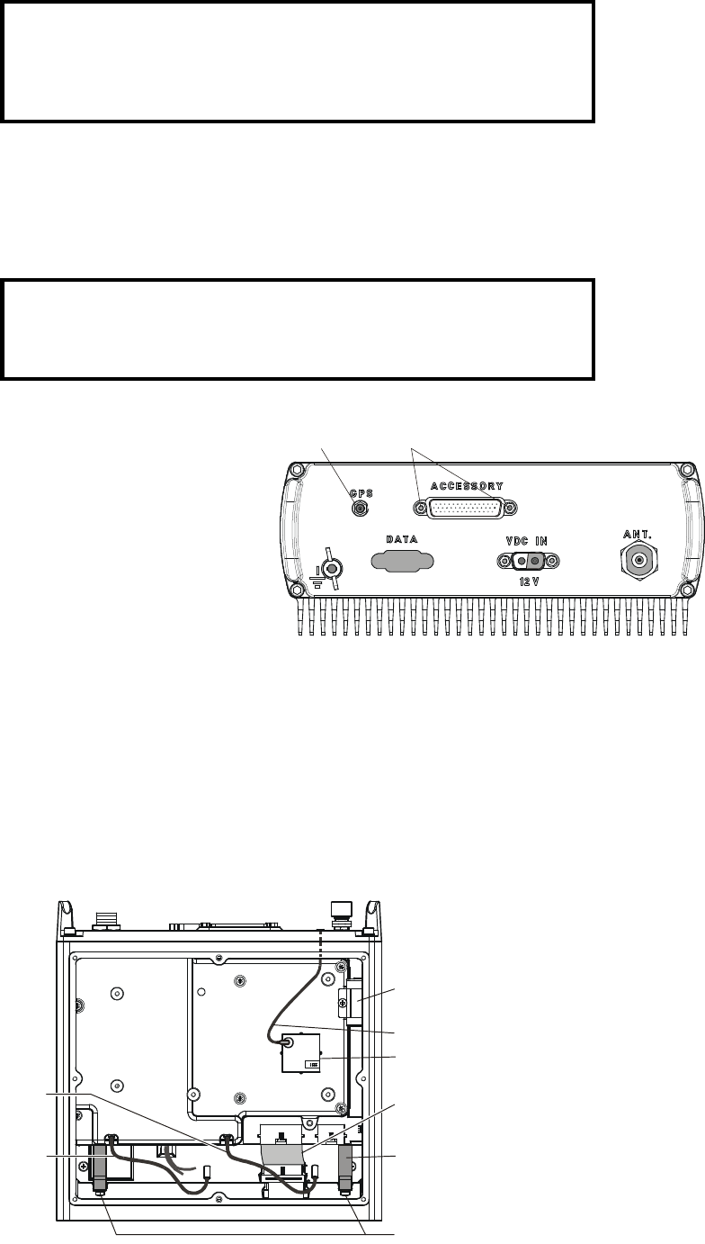
MM-E 2072-09333-00
3-22
CAUTION
The rear panel need not be removed to gain access to the modules.
Do not attempt to remove the rear panel before removing the LORD
and HI POWER modules as explained below.
4. To reassemble the front panel, reverse the procedure described above.
3-6.1.2 Replacing Components of LORD Assembly
The LORD assembly includes the LORD module (covered by a shield), the backup battery, and the
GPS receiver. All these components can be replaced after removing the LORD assembly from the
Micom-Z body.
CAUTION
The ACCESSORY and GPS connectors of the LORD module are
attached to the rear panel.
3-6.1.2.1 Removal of LORD Assembly
1. If necessary, open the Micom-Z case in
accordance with para 3-6.1.1.
2. Release the two fasteners of the
ACCESSORY connector.
3. Release the nut of the GPS connector.
The recommended tool is Mfg. Cat. No.
2072-08013-00.
Nut
Fasteners
4. Refer to Figure 3-13: disconnect the coaxial RX and TX cables from the LORD module
connectors.
5. Disconnect the flat cable connected to the HI POWER module.
6. Release the two screws fastening the LORD handles to the chassis. Keep screws and washers
for reuse.
7. Carefully pull the handles to remove the LORD assembly. After moving the assembly by 2 to 3
centimeters (one inch), push the GPS connector in, and then continue to pull out the LORD
module. Make sure that the GPS connector is pulled out together with the assembly as the
LORD assembly is retracted.
Backup Battery
Flat Cable to HI POWER Module
LORD Handles (2 places)
Handle Fastening Screws
GPS Receiver
TX Cable
RX Cable
LORD
GPS Cable
Figure 3-13. Removal of LORD Assembly
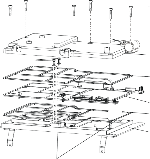
MM-E 2072-09333-00
3-23
3-6.1.2.2 Replacing the Backup Battery
The backup battery is fastened by a clamp to the top of the LORD module, and its harness connects to
connector J4 on the module. Before starting, pay attention to the orientation of the battery.
1. Disconnect the battery harness from connector J4 of the LORD module.
2. Release the screw fastening the battery clamp, and then remove the battery.
3. Place the replacement battery in position, in accordance with its original orientation, and then
fasten it with the clamp removed in step 2 above.
4. Reconnect the battery harness to connector J4 on the LORD module.
3-6.1.2.3 Replacing the GPS Receiver
The GPS receiver is attached to the LORD shield by a pad, and connects by a flat cable to connector
J8 on the LORD module. Before starting, pay attention to the orientation of the GPS receiver on the
LORD shield.
1. Release the flat cable connected to the GPS receiver.
2. Pull the GPS receiver case, to separate it from the attachment pad on the LORD shield.
3. Place the replacement GPS receiver in the correct position on the shield, and press its case to
attach it to the shield.
4. Reconnect the flat cable from the LORD module to the GPS receiver.
3-6.1.2.4 Replacing the LORD Module
Refer to Figure 3-14.
Shield Screws
Heatsink Screws
Shield
Upper RFI Contacts
Lower RFI Contacts
LORD Module
LORD Base
Spread heatsink compound on these surfaces
Figure 3-14. Removal of LORD Module
1. Disconnect the battery harness from connector J4 of the LORD module.
2. Release the eight screws that fasten the shield. Keep screws and washers for reuse.
3. Remove the shield and upper RFI contacts.
4. Release the two heatsink screws. Keep screws and washers for reuse.
5. Pull the LORD module straight up, and remove it.
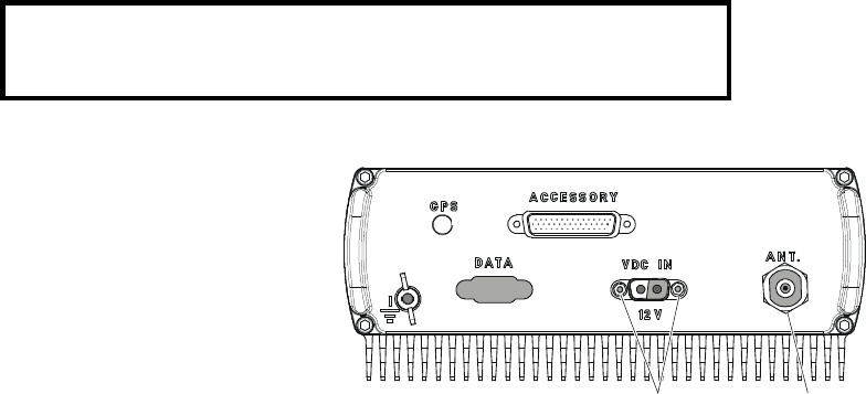
MM-E 2072-09333-00
3-24
6. Clean the remnants of heatsink compound from the areas identified in Figure 3-14, and then
spread a thin layer of fresh compound.
7. Position the replacement LORD module over the lower RFI contacts, place them together in
their original positions on the LORD base, and then fasten the LORD module with the two
heatsink screws removed in Step 4 above.
8. Position the upper RFI contacts over the LORD module, place the shield over the assembly, and
then fasten the shield with the eight screws removed in Step 2 above.
9. Reconnect the battery harness to connector J4 on the LORD module.
3-6.1.2.5 Reinstalling the LORD Assembly
1. Insert the LORD assembly in the corresponding slot of the body assembly, slide it halfway, and
then insert the GPS connector in its hole in the rear panel.
2. Fasten the GPS connector with its nut. The recommended tool is Mfg. Cat. No. 2072-08013-00.
3. Push the LORD assembly fully into the body assembly, and then fasten the ACCESSORY
connector to the rear panel with its two fasteners.
4. Fasten the two LORD handles to the body assembly with the two original screws.
5. Reconnect the coaxial RX and TX cables to the LORD module connectors.
6. Reconnect the flat cable connected to the HI POWER module.
7. You may now close the Micom-Z case in accordance with para. 3-6.1.1.
3-6.1.3 Replacing the HI POWER Module
The HI POWER module is installed on a heatsink, fastened to the body assembly by nine screws. The
module is also attached to the VDC IN connector, and is connected by a coaxial cable to the ANT
connector.
CAUTION
The ANT and VDC IN connectors are attached to the rear panel.
3-6.1.3.1 Removing the HI POWER Module
1. Remove the LORD module in
accordance with para. 3-6.1.1.
2. Release the two fasteners of the VDC
IN connector.
3. Release the nut of the ANT connector.
4. Disconnect the cables connected to the
front side of the HI POWER module.
Nut
Fasteners
5. Refer to Figure 3-15, and release the nine screws fastening the module to the body. Keep screws
and washers for reuse.
6. Insert the tip of a narrow blade screwdriver in the slot located under the HI POWER module
heatsink, and press lightly to raise the module.
7. You can now pull the HI POWER module out: after moving the assembly by 2 to 3 centimeters
(one inch), push the ANT connector in, and then continue to pull out the HI POWER module.
Make sure that the ANT connector is pulled out together with the assembly as the HI POWER
assembly is retracted.
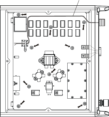
MM-E 2072-09333-00
3-25
ANT Cable
Figure 3-15. Removal of HI POWER Module
3-6.1.3.2 Installing the Replacement HI POWER Module
1. Clean the remnants of heatsink compound from the body assembly and the HI POWER module.
2. Spread a thin layer of fresh compound on the bottom area of the HI POWER module.
3. Route the coaxial cable with the ANT connector over the HI POWER module as shown in
Figure 3-15.
4. Insert the HI POWER module in the corresponding slot of body assembly, slide it halfway, and
then insert the ANT connector in its hole in the rear panel.
5. Fasten the ANT connector with its nut.
6. Push the HI POWER module fully into the body assembly, and then fasten the VDC IN
connector to the rear panel with its two fasteners.
7. Fasten the HI POWER module to the body with the nine original screws.
8. Reconnect the coaxial cables between the LORD and HI POWER modules in accordance with
Figure 3-13.
9. Reconnect the flat cable between the LORD and HI POWER modules in accordance with
Figure 3-13.
10. You may close now the Micom-Z case in accordance with para. 3-6.1.1.
3-6.1.4 Replacement of Components on Front Panel Assembly
3-6.1.4.1 Replacement of CONTROL HEAD Module
Refer to Figure 3-16.
1. Release the 13 screws fastening the RF shield. Keep screws and washers for reuse.
2. Remove the RF shield.
3. Disconnect the speaker cable from the CONTROL HEAD module.
4. Remove the CONTROL HEAD module. Make sure that the keypad and the inserts remain in
their place, on the front panel.

MM-E 2072-09333-00
3-26
NOTE
To remove the LCD, release its four fastening screws, and then
disconnect it from the module. Also disconnect the two harnesses
connected to connectors P2 and P4 on the module.
5. If necessary, move the LCD to the replacement module.
6. Orient the replacement module in accordance with Figure 3-16, and place it on the spacers.
7. Reconnect the speaker cable to the corresponding module connector.
8. Reinstall the RF shield.
LCD
Screws
Front Panel Keypad Inserts Speaker
Speaker Holder
Speaker Screws
Spacers
RF Shield
Shield Screws
Gasket
CONTROL HEAD
Module
Speaker
Cable
Figure 3-16. Replacement of CONTROL HEAD Module
3-6.1.4.2 Replacement of Speaker
1. Release the 13 screws fastening the RF shield. Keep screws and washers for reuse.
2. Remove the RF shield.
3. Disconnect the speaker cable from the CONTROL HEAD module.
4. Release the screws fastening the speaker holder, and then remove the speaker. Keep the gasket
and holder for reuse.
5. Install the replacement speaker by reversing the procedure given above.
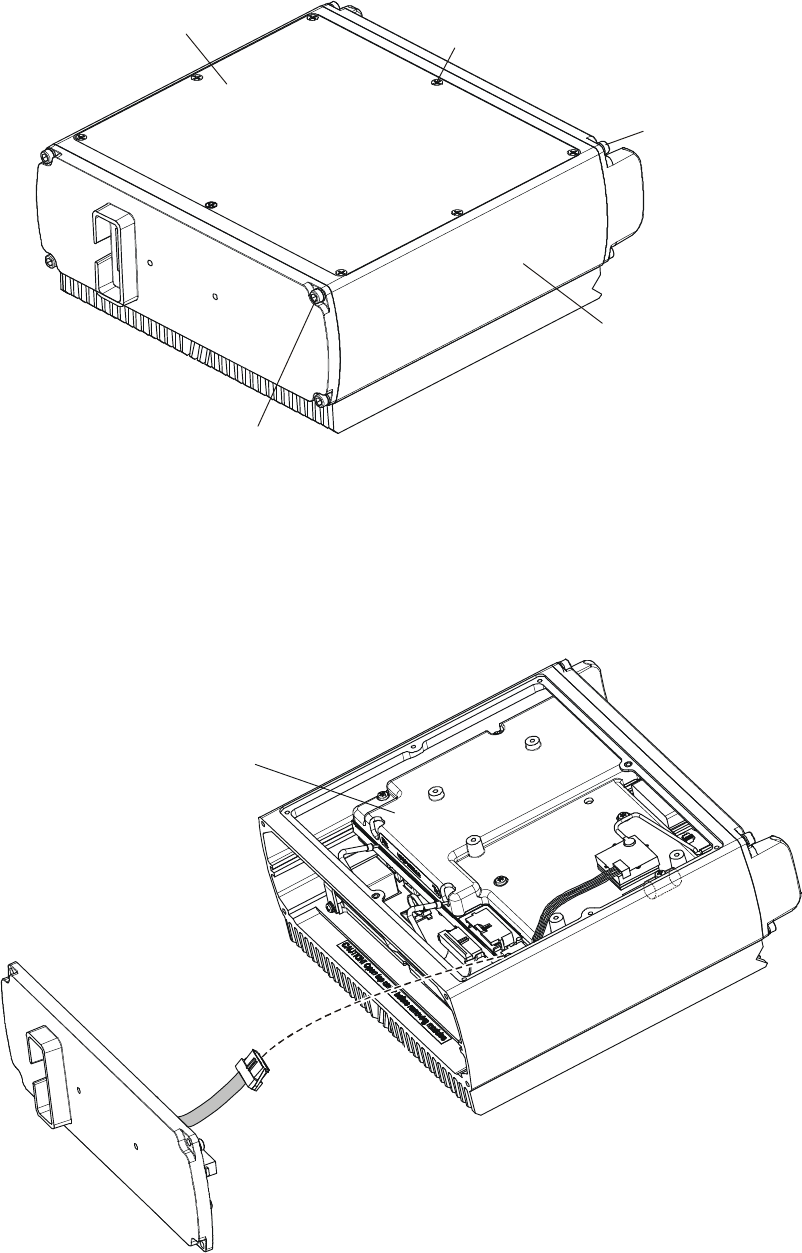
MM-E 2072-09333-00
3-27
3-6.2 Repair of Micom-Z Trunk-Mount Version
3-6.2.1 Gaining Access to Modules
1. Refer to Figure 3-17: release the 8 screws fastening the top cover, and then remove the top
cover.
Top Cover
Top Cover
Fastening Screws
(8 places)
Rear Panel
Fastening Screws
(4 places)
Front Cover
Fastening Screws
(4 places)
Body Assembly
Figure 3-17. Gaining Access to Micom-Z Trunk-Mount Version Modules
2. Release the four screws fastening the front cover to the body assembly. Keep screws and
washers for reuse.
3. Carefully separate the front cover, and then disconnect the flat cable connecting the front cover
to the LORD connector. Figure 3-18 shows the front cover after being removed.
LORD
Module
Flat Cable
to LORD
Front Cover
Figure 3-18. Micom-Z Trunk-Mount Version with Front Cover Removed
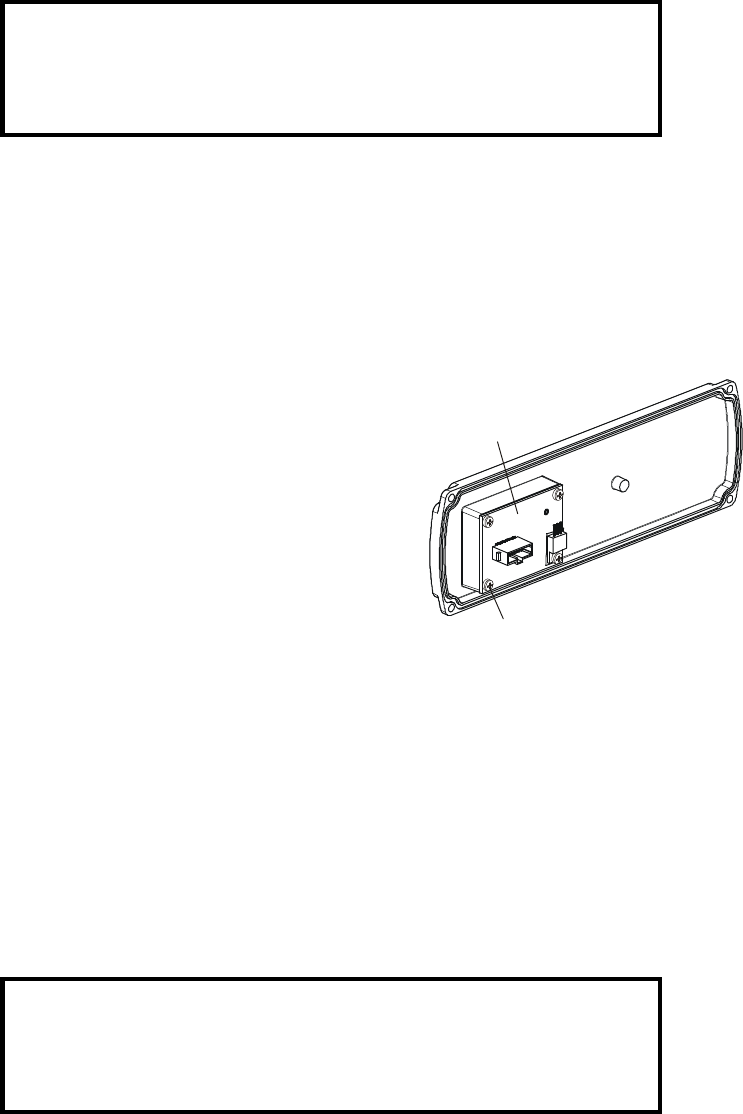
MM-E 2072-09333-00
3-28
CAUTION
The rear panel need not be removed to gain access to the modules.
Do not attempt to remove the rear panel before removing the LORD
and HI POWER modules as explained below.
4. To reassemble the front cover, reverse the procedure described above.
3-6.2.2 Replacing Components of LORD Assembly
Refer to para. 3-6.1.2.
3-6.2.3 Replacing the HI POWER Module
Refer to para. 3-6.1.3.
3-6.2.4 Replacement of INTERCONNECTION Module
1. Remove the front cover in accordance with
para. 3-6.2.1.
2. Release the four screws fastening the
INTERCONNECTION module to the front
cover. Keep screws and washers for reuse.
3. Remove the INTERCONNECTION module.
4. Position the replacement module, oriented as
seen in the figure, on the front cover, and then
fasten it with the four original screws.
INTERCONNECTION
Module
Fastening Screws
(4 places)
3-6.2.5 Replacement of CONTROL HEAD Module on Control Head Assembly
Refer to Figure 3-19.
1. Release the 13 screws fastening the rear panel of the control head. Keep screws and washers for
reuse.
2. Remove the rear panel.
3. Release the nine screws fastening the CONTROL HEAD module to the front panel. Keep
screws and washers for reuse.
4. Remove the CONTROL HEAD module. Make sure that the keypad and the inserts remain in
their place, on the front panel.
NOTE
To remove the LCD, release its four fastening screws, and then
disconnect it from the module. Also disconnect the two harnesses
connected to connectors P2 and P4 on the module.
5. If necessary, move the LCD to the replacement module.
6. Orient the replacement module in accordance with Figure 3-19.
7. Fasten the replacement module with the nine original screws removed in Step 3.
8. Reinstall the rear panel on the control head.
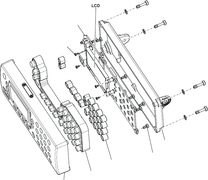
MM-E 2072-09333-00
3-29
LCD
Screws
Front Panel
Module Fastening
Screws
(9 places)
Inserts
Rear Panel
Keypad
CONTROL HEAD
Module
Rear Panel
Captive Screws
(4 places)
Figure 3-19. Replacement of CONTROL HEAD Module
MM-E 2072-09333-00
3-30
Intentionally Left Blank

MM-E 2072-09333-00
A-1
Appendix A
SCHEMATIC CIRCUIT DIAGRAMS
NOTE
Components designated as OPTION or LAB in the schematic circuit
diagrams are optional, and are not installed on the PCBs. Therefore,
ignore such components.
MM-E 2072-09333-00
A-2
Intentionally Left Blank
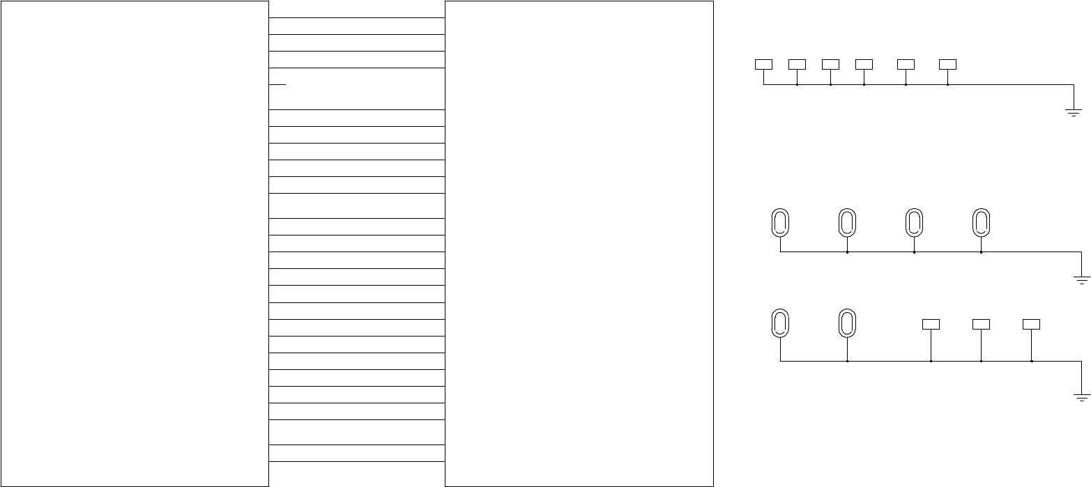
MM-E 2072-09333-00
HOLE_157
DR5
1
G
ND
G
ND
_S
LOT
_3
S
H5
GND
1
GND
1
LOW_RF
3.3V
AMB _TEMP
A_D_DATA
CONVST
D2A_OVEN_SEL
DIGITAL_16.8Mhz
DSM_AGC_EN
DSM_OUTPUT_1.05Mhz
FRAC_N_1_SEL
FRAC_N_2_SEL
L OW_RF_SEL
NOISE_CONTROL
PENDULL UM_SEL
PTT_IN
PWR_LEVEL
SPI_CLK
SPI_CLK _UP
SPI_DATA _OUT
SPI_DATA _OUT_UP
SR_CLK
SR_DATA
SYNTH_LOCK
VCO1_SEL
VCO2_SEL
VCO3_SEL
1
G
ND
GND
_EDGE_2
SH8
1
G
ND
S
H1
G
ND_SL OT_1
GND
1
S
H2
G
ND
_S
LOT
_5
GND
1
GND
_EDGE_3
ED
G
E1
GND
1
SH3
GND_SLOT_2
GND
1
SH4
GND_SLOT_6
SR_DATA
SYNTH_LOCK
VCO1_SEL
VCO2_SEL
VCO3_SEL
GND
_EDGE_1
SH6
1
G
ND
S
H7
G
ND
_S
LOT
_4
CPU
_
AUD
IO
3.3V
AMB _TEMP
A_D_DATA
CONVST
D2A_OVEN_SEL
DIGITAL_16 .8Mhz
DSM_AGC_EN
DSM_OUTPUT_1.05Mhz
FRAC_N_1_SEL
FRAC_N_2_SEL
LOW_RF_SEL
NOISE_CONTROL
PENDULL UM_S EL
PTT_OUT
PWR_LEVEL
RESET
SPI_CLK
SPI_CL K_UP
SPI_DA TA_OUT
SPI_DATA_OUT_UP
SR_CLK
HOLE_138
DR4
1
G
ND
DR1
1
G
ND
HOLE_138
DR2
1
G
ND
DR6
1
G
ND
HOLE_138
DR3
1
G
ND
HOLE_138 HOLE _157
Figure A-1.A. LORD Module, Schematic Circuit Diagram (Sheet 1 of 15 – Module Interconnection Diagram)
A-3/A-4
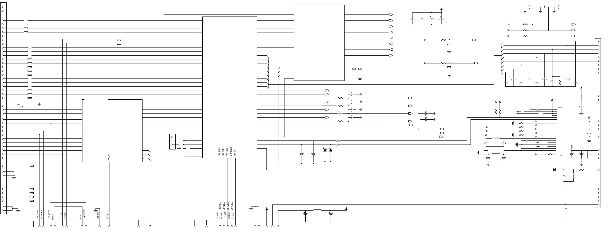
MM-E 2072-09333-00
QUAD
CONNECTOR
J5
CONN
ECTOR
5vdc
BATTERY
J3
500w/1kw
500w /1kw
13
.
8v
dc
J4
J6 -
CON
TROL HEAD
astic/modem
SECTION
SECTION
500
w/
1kw
p
ll _1_filter
500w
/1kw
p
ll_1_fil ter
UART
O
P
T
I
ON
astic
J7
TO RF
CONNECTOR
CONNECTOR
A
MP_
FWD
26
ACCESSORY
TO
RF
CONNECTOR
H
I
GH POWER
SE
CTI
ON
TO RF
500w/1kw
13
.
8v
dc
3
9
15
GND
1916
SPARE_1
18
RXA
R9583
SPARE_2
100NF
C9548
10K
TX_AUDIO+
8
TXD38
CR9077
MM
B
D914T
3
R7001
470
14
RX_AUDIO_OUT
34
6
SPKR-1
V_REV_
TUNE
8
4
7
EXT_ALARM
20
EXT_RX_AUDIO+
4
A+
RX_AUDIO+
RX_AUDIO-
RX_AUDIO_IN
RX_AUDIO_OUT
SPKR+
SPKR-
SQ_SW
TX_AUD IO_IN
TX_AUD IO_OUT
U|D_
VPP21
F1
FUSE_MINISMD050
AUDIO UNIT
AUDIO_C_P_SW
CS_
EXT_ALARM
EXT_ALAR M_CONT
EXT_AUDIO_SW
EXT_RX_AUD IO+
EXT_RX_AUD IO-
EXT_RX_DATA+
EXT_RX_DATA-
EXT_TX_AUDIO+
EXT_TX_AUDIO-
INC_
ISB_EXT_AUD IO_SW
MIC
PA_ MU TE
23
23
SW_
A+
C9568
0.1
uf
SQ_GATE
R9598
4.7k
1
40
3.3V
C7011
TX_AUDIO_IN
C7003
0.1
uf
FL19
IN OUT
FL6
0.1
uf
OP
T
ION
R9609
47K
R7007
SW_A+
FL?
C9534
270PF
9
100NF
C7031
C9551
0.1
uf
TX_AUDIO-
22UH
L
9080
100NF
FL31
IN OUT
FL33
IN OUT
35
3.3V
A+
C7029
270PF
VCC
RX_AUDIO_IN
8
19
C7028
22
V_
F
WD_HF
7
13
SW_
A+
31
R7006
KW_ON_OFF
27
5
470
OP
T
ION
R9612
FWD_CLOSE_LOOP
R9611
OP
T
ION
25
C7014
0.1
uf
A+
15
FREEZE|KW_TUNE
OP
T
ION
R9668
12
R9527
470
5
R9614
100
VCC
23
24
6
7
8
9
1
2
3
4
12
13
14
15
16
17
18
19
20
21
22
4
9
VCC
CF
2124V0
R0
J7
10
11
5
GND18
0.1
uf
C9556
33
6
100
R9613
SW_
A+
BAT-
1
SW_
A+
1
R9551
0
26
C7017
0.1
uf
T
UNE_CUR_
LIM
6
GND
C7027
100NF
5
5.6V
VR5009
V_REV_HF
9
EXT_RX_AUDIO-
22
270PF
C7021
VR5010
5.6V
F
WD_C
L
OSE_
LOOP
RXC
RXC_MODEM_TTL
RXD
SPI_CLK
SPI_DATA_OUT
SQ_GATE
SQ_SW
STOP_SCAN
SYNTH_LOCK
TU_CH_CHNG
TU_CUR_LIM
TXA
TXB
TXC
TXC_MODEM_TTL
TXD
U|D_
VCO1_SEL
VCO2_SEL
VCO3_SEL
VPP
VP_PTT
V_FWD_HF
V_FWD_PA
V_REV_HF
V_REV_TUNE
DSO DSP_CS
DSP_REQ
DSP_RESET
DSP_RW
EXT_ALAR M_CONT
EXT_AUDIO_SW
EX_RESET
FRAC_N_1_SEL
FRAC_N_2_SEL
FREEZE
HOST_ADD(0:18)
HOST_DATA(0:15)
INC_
KW_ON_OFF
KW_PTT
LOW_RF_SEL
NOISE_CONTROL
PA_ INHIB
PA_ MUTE
PA_TE MP
PEND|OCXO_SEL
PTT_IN_CW
PTT_IN_DATA
PTT_IN_VOICE
PTT_OUT
PWR_LEVEL
RESET
RXA
RXB
1
FL27
IN OUT
HOST_UNIT
AMB_TEMP
AMP_ON_OFF
AUDIO_C_P_SW
AUDIO_SW
BAT_ IN
BIT
BKPT_DSCK
CLK_ IN
CS_ D2A_OVEN_SEL
DSI
C7020
0.01UF
0.1
uf
C7022
270PF
C9563
TP_1
TXB29
GND
18
C7012
0.1
uf
2
C7001
10PF
20
VCC
1
FL3
17
REV_C
LOSE_LOOP
2
15
SW_
A+
29
C7009
270PF
GND
46
4.7k
R9597
5
L
9081
22UH
0.1
uf
C9564
SW_
A
+_CONT
1
10
6
RXC
28
A
MP_ON_O
FF
17
PTT_IN_CW
10
FL13
3.3V
22
STOP_SCAN
2
0.1
uf
C7019
BKPT_DSC|KW_ ALC
37
EXT_TX_AUDIO-
7
VCC
FL7
TX_AUDIO_OUT
32
VCC
2
P
A
_
T
EMP
10
FL23
IN OUT
FL4
T
P_2
7
7
0
R9633
0.1
uf
C7004
3
R9582
10K
R9610
OP
T
ION
P
A
_INHI
BIT
470
R9528
45
TXC
39
B
IT
16
FL30
IN OUT
FL10
GND
6
TXA
16
C7008
270PF
EXT_TX_AUDIO+
DSI|KW_C_C
12
C9620
15UF
L
9085
22UH
3
FL12
FL2
EXT_TX_AUDIO_ISB
42
3
SW_A+
11
SPKR+
2
AMP_FWD
36
FL11
270PF
C7007
24
R9529
470
EXT_TX_AUD IO_ISB
HOST_ADD(0:18)
HOST_DATA(0:15)
HOST_RW
ISB_EXT_AUD IO_SW
MIC
PTT_OUT
RX_AUD IO+
RX_AUD IO-
SR_CLK
SR_DATA
4
DSO|FAN_ON_OFF
C7016
0.1
uf
D
SP
_UNIT
16.8MHZ
3.3V
AUDIO_SW A_D_DATA
CLK_OUT
CONVST
DSM
_AGC_EN
DSM_OUT
DSP_CS
DSP_REQ
DSP_RESET
EXT_RX_AUD IO_ISB
A
MP_REV
24
AMP_REV30
44
0.1
uf
C7013
1
A+
11
EXT_RX_DATA+
RXD
31
A+
13
FL24
IN OUT
C9562
270PF
FL9 OUT
ON_OFF_CONT
242
BAT+
2
C7010
0.01UF
8
C7030
15
uf
0.1
uf
C7015
14
3
C7006
33UF
A+
14
FL8
REV_CLOSE_LO OP
C9532
270PF
EXT_RX_AUDIO_ISB
41
9
2
3
VCC
20
FL29
IN OUT
13
15UF
C9621
V_
F
WD_PA
11
GND
270PF
C9533
33UF
C7005
43
FL14
IN
R7002
470
470
R7000
FL18
EXT_RX_DATA-
270PF
C9535
R9530
470
5
FL28
IN OUT
T
UNE_CH_CH
ANGE
4
C7018
21
0.1
uf
RXB33
R7003
470
17
FL32
IN OUT
FL1
10PF
C7002
PTT_IN_DATA
KW_PTT
A+_13.8_DC
8
EX_RESET
RX
C
_MODEM_T TL
13.8VDC
RX_AUD
IO_IN
RX_AUD
IO_OUT
TX_AUD
IO_IN
TX_AUD
IO_OUT
F_VP_VO
C
ODER_PTT
RESET
PTT_
I
N_VO
ICE
PTT_
I
N_DATA
K
W_PTT
SPI_
CLK
SPI_DATA_OUT
FRAC_N_1_SEL
RX_AUDIO_IN
PTT_IN_VOICE
FRAC_N_2_SEL
BAT_IN
A
M
B_TEMP
TX
C
_MODEM_T TL
SPI_CLK
RESET
PWR_LEVEL
PTT_OUT
PENDULLU M_SEL
HOST_DATA(0:15)
HOST_ADD(0:18)
VCO3
VCO2
VCO1
SYNTH_LOCK
SPI
_DATA_OUT
SR_CLK
BAT_
IN
F_VP_VOCODER_PTT
RX_AUDIO_OUT
TX_AUDIO_IN
TX_AUDIO_OUT
LOW_RF_SEL
SPI
_CLK_UP
V
CO1
V
CO2
V
CO3
VCO2_SEL
VCO3_SEL
VCO1_SEL
NOISE_CONTROL
DSM
_AGC_EN
CONVST
A_D_DATA
3.3V
SR_DATA
D
I
G
I
TAL_16.8 Mhz
DSM_OUTPUT_1.05Mhz
SPI
_DATA_OUT_UP
D2A_OVEN_SEL
HIGH_POWER(1:9)
AUDIO(1:3)
Figure A-1.B. LORD Module, Schematic Circuit Diagram (Sheet 2 of 15 – DSP Subsystem Organization)
A-5/A-6
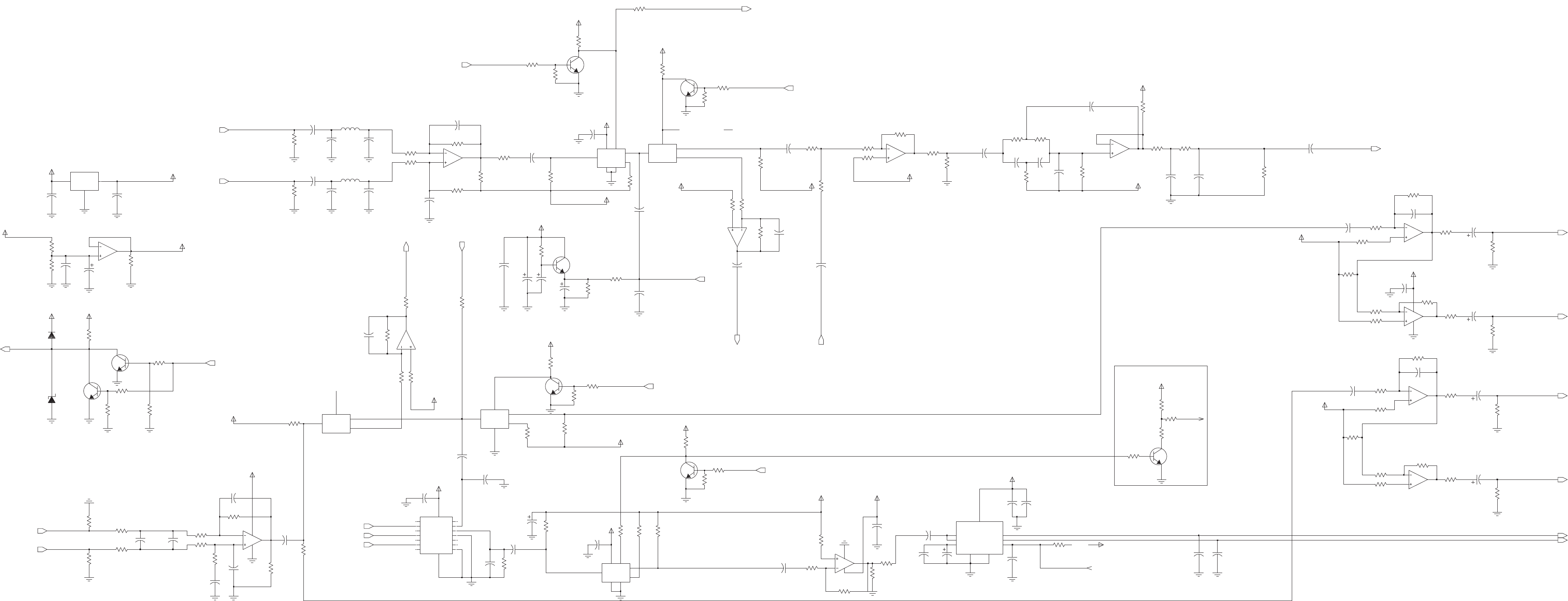
C4044
33UF
THIS IS FULL MUTE
MC33174
U6082
6
5
7
4V_AUDID_BIAS
C9554
10UF
C9558
0.1UF
R4057
10K
10K
R9590
R4014
220
R4003
10K
R4015
8V_AUDID_ISB
220
SW_A+
C4002
270PF
C9549
100NF
4V_AUDID_BIAS
R4007
10K
R4026
100K
20K
R4005
301K
1UF
C9542
330PF
R4021
1000PF
C4021
C4020
MC33174_PWR
U4003
13
12
14
4
11
5
Z1 3
1000PF
C4068
20K
R4083
HC4053-M_C
U6084
CL
6
CZ
9
Z
4
Z0
R4087
Q4000
3904L
2.7K
R9589
10K
3K
R4008
10UF
C4040
4V_AUDID_BIAS
4V_AUDID_BIAS
C4055
1UF
C4057
0.01UF
4V_AUDID_BIAS
C4056
680PF
R4067
2K
A+
R9580
20K
3.3K
R4401
C4062
1UF
1000PF
C4022
20K
R9578
3.3K
R4058
R4071
39K
330PF
C4052
1K
R4064
20K
R9581
1K
R9599
R4088
20K
R4063
10K
8V_AUDID_ISB
R4086
6.8K
R4012
Q4002
3904L
10K
20K
R4068
51K
R9587
3904L
Q9069
R9602
560
8.25K
R4011
10K
R4004
U4000
MC33174
6
5
7
VCC
R4022
27K
R4055
R4200
100K
39K
100K
R9532
R4030
2K
10K
R4049
R4061
20K
22UH
10K
R9586
4V_AUDID_BIAS
L4002
HC4053-M_PWR
U6084
CX
11
GND
8
VCC
16
VEE
7
X
14
X0 12
X1 13
20K
20K
R4033
R9577
U6085
HC4053-M
10
CY
15Y
2
Y0
1
Y1
2K
R4009
R4051
4.7K
680PF
C9544
C9614
1000PF
C4064
8V_AUDID_ISB
0.39UF
270
R4060
10UF
C4045
27K
R4080
1000PF
C4008
3904L
Q9067
680PF
C4023
C4074
0.39UF
R4024
100K
C4004
1UF
100K
R4059
15UF
C4070
R9600
1K
C4058
1UF
22UH
L4001
12PF
C4060
9
10 8
C4007
1000PF
R9579
MC33174
U4003
MMBZ5254L
VR4000
20K
C4053
1UF
4V_AUDID_BIAS
4V_AUDID_BIAS
4V_AUDID_BIAS
SW_A+
SW_A+
1
MC33174
U6082
2
3
1
4V_AUDID_BIAS
4
OUT2 6
RR
3
VP
7
U4003
MC33174
23
TDA1519A
U4002
GND1
2
GND2
5
INV
9
M|SS 8
NINV
1OUT1
R4047
10K
8V_AUDID_ISB
R4066
27K
R4019
20K
CY
10
Y
15
Y0 2
Y1 1
604
R9690
HC4053-M
U6084
R4037
2.7K
C4061
10UF
5.6K
R4016
R9698
0
10UF
C4043
SW_A+
U4000
9
10
8
C9531
1UF
3904L
8V_AUDID_ISB
150K
R4069
Q4004
R4020
OPTION
ENH
R9536
3.3K
1UF
C4012
10UF
C4054
C4042
100NF
20K
R4043
0.01UF
C4039
7
U4000
MC33174
2
3
1
U4003
6
5
C4071
1UF
1UF
C4017
C9543
680PF
R4076
OPTION C4065
1000PF
6.8K
R4050
R4079
2K
10K
R4018
C9555
4.7UF
R4070
150K
R4074
10K
R9593
10K
10K
R4041
R9691
604
R4062
10K
12
14
VCC
4
11
150K
R9596
R4044
560
U4000
MC33174_PWR
13
R4075
270
C4009
1UF
R9601
560
0
R9697
R9592
10K
Q9066
8V_AUDID_ISB
R9538
270
4V_AUDID_BIAS
3904L
1000PF
C4066
0.1UF
R9591
10K
C9559
1000PF
C4047
5.11K
R9531
8V_AUDID_ISB
CR9070
MMBD914T
390PF
C4014
10UF
C9553
3904L
Q4003
39K
R4078
11
CX
8
GND
16
VCC
7
VEE
14X
12
X0
13
X1
8V_AUDID_ISB
R4053
100K
U6085
HC4053-M_PWR
R4028
14.7K
R4017
6.8K
1UF
C4010
8V_AUDID_ISB
10K
R4082
100
R9576
27K
R9688
C4000
33NF
10K
R4065
20K
R4025
1 U|D_
14VB
16
VCC
12VH
9VL
13VW
10K
R9594
6 CS_
8
GND
4 INC_
2 NC1
3 NC2
5 NC3
7 NC4
15NC5
11NC6
10NC7
13
12
14
4VCC
11
U6081
DS1666
MC33174_PWR
U6082
680PF
C4073
51K
R4077
17.8K
8V_AUDID_ISB
10K
R9676
R9675
C4011
1UF
R4052
10K
R4054
10K
270
R9537
R9559
C4035
1UF
R4085
1K
8V_AUDID_ISB
150K
8V_AUDID_ISB
8V_AUDID_ISB
27K
R4006
Q4001
3904L
4V_AUDID_BIAS
0.1UF
C9561
C9545
330PF
560
R4013
1500PF
C4015
C4300
100NF
C4038
C4018
0.01UF
U6098
MC78M08BDTRK
4
GND
1VIN 3
VOUT
100NF
0.1UF
C9615
4.7UF
C4069
1UF
C4016
1UF
C4072
10K
R9588
R9603
560
100NF
C4067
R4073
10K
R4084
R4072
10K
C4013
150K
R9595
150K
3.3NF
U6082
MC33174
9
10
8
18
R4081
10K
R4056
SW_A+
12PF
100K
R9533
C4059
TDA_MUTE
AUDIO_C_P_SW
IN_AUDIO_C_P_SW
TDA_MUTE
RX_AUDIO_OUT
RX_AUDIO_IN
ISB_EXT_AUDIO_SW
MIC_IN
RX_AUDIO+ U|D_
SPKR-
SPKR+
INC_
RX_AUDIO- CS_
EXT_RX_DATA-
EXT_RX_AUDIO-
SQ_SW
IN_AUDIO_C_P_SW
EXT_ALARM _CONT
EXT_ALARM
EXT_RX_DATA+
PA_MUTE
EXT_RX_AUDIO+
TX_AUDIO_OUT
TX_AUDIO_IN
EXT_AUDIO_SW
EXT_TX_AUDIO-
MIC
EXT_TX_AUDIO+
A-7/A-8
MM-E2072-09333-00
Figure A-1.C.LORDModule,SchematicCircuitDiagram
(Sheet3of15– AudioCircuits)
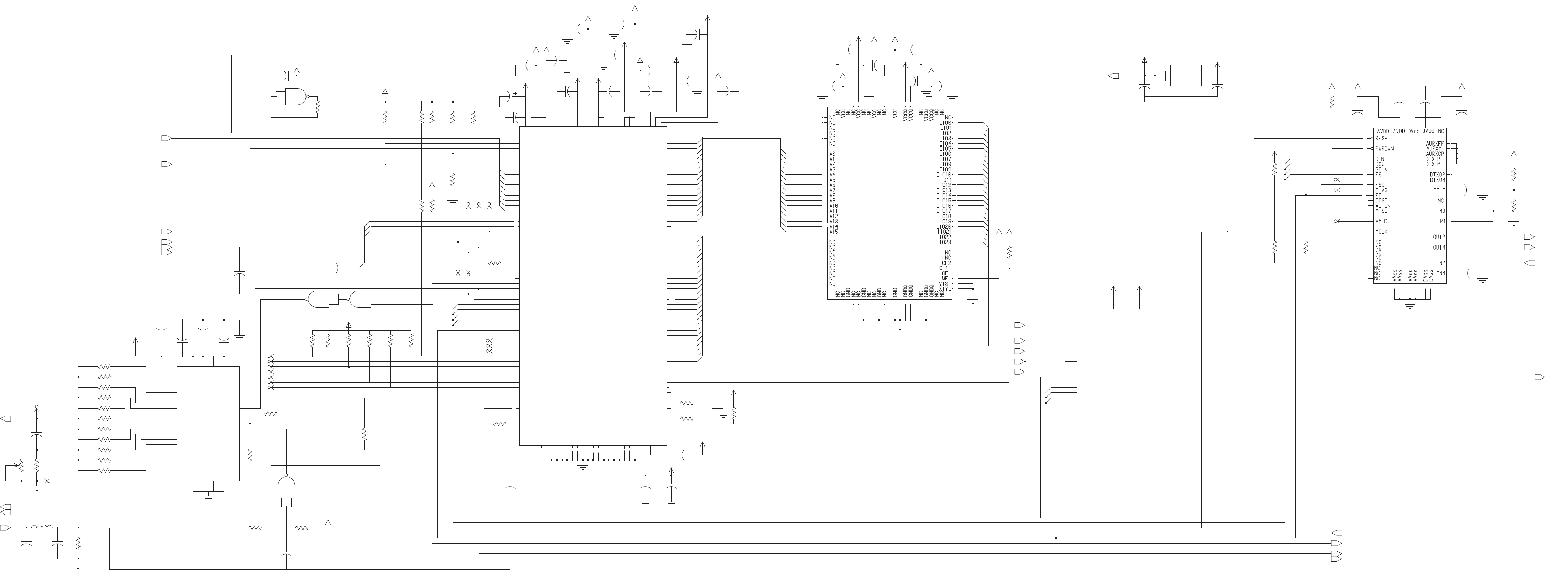
A-9/A-10
MM-E2072-09333-00
SCI
JTAG
TIMER
BUS
PULSE MODE
CONTROL
ADDRESS
BUS
ISB
INTERFACE
64K X24
MODE 7
NP-R6500
HOST
DATA
BUS
PLL
ESSI0
ESSI1
ONCE
MODE 5
R9420
FAST SRAM
FRAMEMODE
MASTER
CODEC_1
SPARE 0.01UF
C9488
39K
3.3V
3.3V
8
DE_
VMID_TP
13
C9484
0.01UF
3.3V
15
VCC
15
10
0.1UF
C6016
C9489
1
3.3V
FLAG_TP
0.01UF
10
R9419
39K
C9498
0.1UF
3.3V
10K
R6042
11
3.3V
3.3V
10
100
R6041
C9407
0.39UF
0.01UF
C9481
JTAG_RESET
0
R6032
10K
3.3V
R60381.2K
18
10NF
750 R6033
C9496
0.1UF
C6039
TDO
3.3V
17
4
C9508
0.1UF
LOGIC_00
U6065
9
10
8
1
10NF
C9482
3
14
C6010
0.1UF
HREQ_
HRW
16
5
6
0.1UF
C6004
1
U6065
4
VCC
TXD
RXD
1
5
3.3V
R9513
0
8
1K
R6500
910 R6027
3.3V
3.3V
OPTION
R9495
0.1UF
12
OPTION
C6019
VIN
2VOUT1
VOUT24
3.3V
13
R9425
C9419
1UF
40212212354
U6097
ADP3338AKC-3.3
1
GND
3
15
3.3V
9
17
2
3
VCC
2
VCC
2
18
56
91
126
8
25
38
VCCP
45
67
WR_
XTAL
53
14
74
80
86
95
57
65
103
111
119
129
2
STD1
TA_ 62
141 TCK
140 TDI
139 TDO
29 TI00
TI01
28
27 TI02
142 TMS_
138 TRST_
TXD
4SC01
3SC02
SC10
11
144 SC11
SC12
143
17 SCK0
16
SCK1
SCLK
15
7SRD0
1
SRD1
10 STD0
MODB|IRQB_
135 MODC|IRQC_
134 MODD|IRQD_
NC1
49
20
NC2
46
PCAP
6
PINIT|NMI
RD_
68
44 RESET
13 RXD
12 SC00
HAD3
40
HAD4
37
HAD5
36
HAD6
35
HAD7
34
HCS_
30
HDS_
21
HREQ_
24
HRW
22
137 MODA|IRQA_
136
26
GNDH
39
GNDP
47
GNDP1
48
HA0
33
HA1
32
HA2
31
HACK_
23
HAD0
43
HAD1
42
HAD2
41
GNDC2
66
GNDD1
104
GNDD2
112
GNDD3
120
GNDD4
130
GNDQ1
19
GNDQ2
54
90
GNDQ3
127
GNDQ4
GNDS1
9
GNDS2
D6 108
D7 109
D8 110
D9 113
5DE_
55 EXTAL
GNDA1
75
GNDA2
81
GNDA3
87
GNDA4
96
GNDC1
58
123
D18 124
D19 125
D2 102
D20 128
D21 131
D22 132
D23 133
D3 105
D4 106
D5 107
CAS_
CLKOUT
59
D0 100
D1 101
D10 114
D11 115
D12 116
D13 117
D14 118
D15 121
D16 122
D17
A9 85
AA0 70
AA1 69
AA2 51
AA3 50
BB_ 64
BCLK 60
BCLK_ 61
71
BG_
63
BR_
52
94
97
98
99
A2 76
A3 77
A4 78
A5 79
A6 82
A7 83
A8 84
U6042
XC56303PV100
DSP
A0 72
A1 73
A10 88
A11 89
A12 92
A13 93
A14
A15
A16
A17
9
7
12
13
11
14
R6020
39K
1
R6034750
U6065
1
GND
3.3V
13
10K
R6002
4
OPTION
R6045
C6020
0.1UF
19
20
R9607
39K
15
6
39K
R9423
FS
TMS
22
12
TRST
VCC
3.3V
R9411
39K
TDI
R9465
1K
680NH
L6000
18
5
C6091
R9410
39K
3.3V
14
6
1UF
OPTION
3.3V
14
23
4
0
R9490
C9506
0.1UF
R6009
39K
5
270PF
C6041
R6016
39K 39K
R9409
19
C9486
0.01UF
0.1UF
21
15
8
0
C6034
SW_A+
SW_EXT_TX_AUDIO_ISB
0.1UF
C9500
9
HYBRID_OPT
AUDIO_SW
EXT_RX_AUDIO_ISB
EXT_TX_AUDIO_ISB
HYB_3.3V
HYB_CODEC_FC
HYB_ESSI_FSD
HYB_ESSI_SCK
HYB_ESSI_SRD
HYB_ESSI_STD
HYB_GND
HYB_MCLK
HYB_RESET
ISB_EXT_AUDIO_SW
PTT_OUT
90
10
21
60
71
92
88
93
5
41
65
91
11
20
61
70
17
40
67
94
95
96
4
5
14
16
26
27
86
15
76
77
78
3
79
80
83
84
85
87
89
43
50
51
2
52
53
54
55
64
66
69
72
73
1
28
29
30
31
38
39
42
18
19
58
22
23
24
25
59
62
63
68
56
57
74
75
6
7
8
9
12
13
99
49
48
47
46
45
44
37
36
98
97
8
U6038
IS61LV6424TQ
82
81
35
34
33
32
100
39K
R9418
8
11
12
SW_A+
39K
1UF
C9472
0
3.3V
R6028
R6000
39K
3.3V
25
8142228
LOAD_DIV 5
2
11
OUT|FIR_1
13
RESET 3
SSI_CLK 10
SSI_DATA 6
1915
VCC4
VCC3
VCC2
VCC1
23
CLK_IN 7
DSM_EN 4
DSM_FS 12
26
27
FIR_2
FIR_3
FIR_4
FIR_5
FIR_6
N.C.1
N.C.2
GND4
GND3
GND2
GND1
FIR_7
FIR_8
FIR_9
FIR_10
FIR_11
16
17
18
19
20
21
24
C9485
0.01UF
U6000
ASIC_DSM
0.1UF
3.3V
3.3V
2
C6013
7
C9421
10UF
0.1UF
OPTION
R9416
C9502
12
2
3.3V
0
9
3
1.2K R6026
1.8K R6022
R9496
39K
3.3V
1.8K R6039
R6040
1.8K
0
R9489
R9422
39K
9
3.3V
HA1
13
100PF
C6015
0.1UF
C9507
39K
R9412
10
13
DSM_OUT
3
0.1UF
C6021
11
20
R9417
39K
14
C6040
270PF
C9501
0.1UF
18
R6035
C9499
0.1UF
11
14
C6000
10UF
0
0
3
2
7
C6014
100PF
C6006
3.3V
1
0.01UF
0.1UF
C9487
SCLK
0
1K
R9464
22
R6036750
4
3
TCK
11
10
6
3.3V
16
10UF
R6018
39K
23
C9420
0
HA2
21
3.3V
13
19
43
HA0
3.3V
36
37
39
41
31
32
44
28
9
8
12
22
21
48
47
10
11
20
27
35
18
7
6
5
4
15 30
14
29
24
38
23
1
2
45 34
33
40
42
46
25
17
16
12
2
U6040
TLV320AIC10
26
3
3.3V
1
2
6
C6002
0.1UF
R6030
39K
C9490
0.01UF
7
C6008
0.1UF
C9515
0.1UF
C9483
0.01UF
R6037
910
U6065
1
2
3
3.3V
R6023
1.8K
7
39K
R9421
SW_EXT_TX_AUDIO_ISB
PTT_OUT
DSP_RESET
DSM_AGC_EN
CLK_OUT
EXT_RX_AUDIO_ISB
AUDIO_SW
ISB_EXT_AUDIO_SW
EXT_TX_AUDIO_ISB
3.3V
RX_AUDIO-
RX_AUDIO+
DSM_OUT
HOST_RW
DSP_REQ
3.3V
MIC
DSP_CS
16.8MHZ
ESSI(0:3)
HOST_ADD(0:18)
DSP_ADDR(0:15)
HOST_DATA(0:15)
DSP_DATA (0: 23)
CONVST
SR_CLK
SR_DATA
A_D_DATA
Figure A-1.D.LORDModule,SchematicCircuitDiagram
(Sheet4of15–DSP SubsystemCircuits)
VCCA1
VCCA2
VCCA3
VCCA4
VCCS1
VCCQ1
VCCQ2
VCCQ3
VCCQ4
VCCC1
VCCD1
VCCD2
VCCD3
VCCD4
VCCH
VCCS2
VCCC2
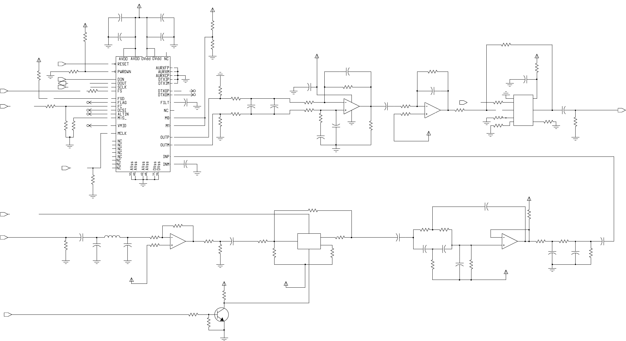
MM-E 2072-09333-00
FRAME MODE
R9640
10K
SLAVE MODE
PULSE MODE
22UH
L9083
100NF
C9575
C9601
12PF
10K
R9663
2K
R
9679
3
.
3V
100
NF
C
9604
8V_AUDID_ISB
274
R
9670
6
5
7
OP
TI
ON
C
9593
R9643
39K
M
C33174
U
6089
R9660
2K
2
.
7NF
C
9597
R9689
OPTION
ALTIN
DTXOP
R
9631
14
.
7K
R
9632
301K
3.3V
C
9585
22NF
R
9687
OPTION
1000PF
C9596
1
.
5NF
C
9594
C9595
1000PF
C9617
1UF
8V_AUDID_ISB 4V_AUDID_BIAS
1
UF
C
9583
R
9699
0
R4002
20K
C
9599
680
PF
R
9645
27.4K
27.4K
R
9646
680
PF
C
9598
R9666
OPTION
OPTION
R9667 FLAG
R9711
OPTION
3.3V
DCSI
R9637
51.1K
13
12
14
4
VCC
11
12PF
C9600
2
3
1
M
C
33174_PWR
U
6089
M
C33174
U
6089 OPTION
R
9685
20K
R
9649
24K
R
9647
100
NF
C
9573
2K
R
9658
R9661
2K
8
1UF
C9584
U6089
MC33174
9
10
10K
R9630
R9642
10K
31
32
44
28
9
8
12
13
19
43
47
10
11
20
27
35
18
36
37
39
41
15 30
24
38
23
22
21
48
25
17
16 7
6
5
4
3.3V
TLV320AIC10
U6088
26
3
1
2
45 34
R
9652
10K
R9659
6.19K
4V_AUD
ID_BIAS
10K
R9641
R9636
100K
R
9653
10K
39K
R9644
1
UF
C
9582
R
9684
OP
TI
ON
51.1K
R9638
6
C
O
M2
IN1
7
IN2
3
NC2
5
1
NO
8
V+
4
V-
2K
R9662
U6096
M
A
X325ESA
2
C
O
M1
100NF
330
PF
C
9602
VMID
C9574
R9629
100K
R9700
150K
R
9628
HC4053-M_C
U6085
CL
6
CZ
9
Z
4
Z0
5
Z1
3
0
R4001
10K
3904L
Q4005
R9655
10K
R4000
4V_AUDID_BIAS
4V_AUDID_BIAS
6.8K
C9581
1UF
8V_AUDID_ISB
1
UF
C
9580
DTXOM
10UF
C9612
330
PF
8V_AUD
ID_ISB
R
9686
OPTI
ON
C
9603
20K
R
9648
C9592
0.39UF
1K
R
9664
10UF
C9611
3
.
32K
R
9657
221
221
R
9672
6.8K
R
9671
R9665
1K
R9654
C9579
100NF100NF
C9578
3
.
32K
R
9656
C
9613
10
UF
10K
R9639
OPTION
R9669
AUDIO_SW
ISB_EXT_AUDIO_SW
R
9678
3
.
32K
HYB_RESET
HYB_ESSI_SRD
HYB_ESSI_STD
HYB_ESSI_SCK
HYB_MCLK
EXT_TX_AUDIO_ISB
HYB_CODEC_FC
P
TT_OUT
EX
T
_RX_
A
UDIO_ISB
A
U
D
I
O_B
IAS
HYB_ESSI_FSD
Figure A-1.E. LORD Module, Schematic Circuit Diagram (Sheet 5 of 15 – ISB Processor Circuits)
A-11/A-12
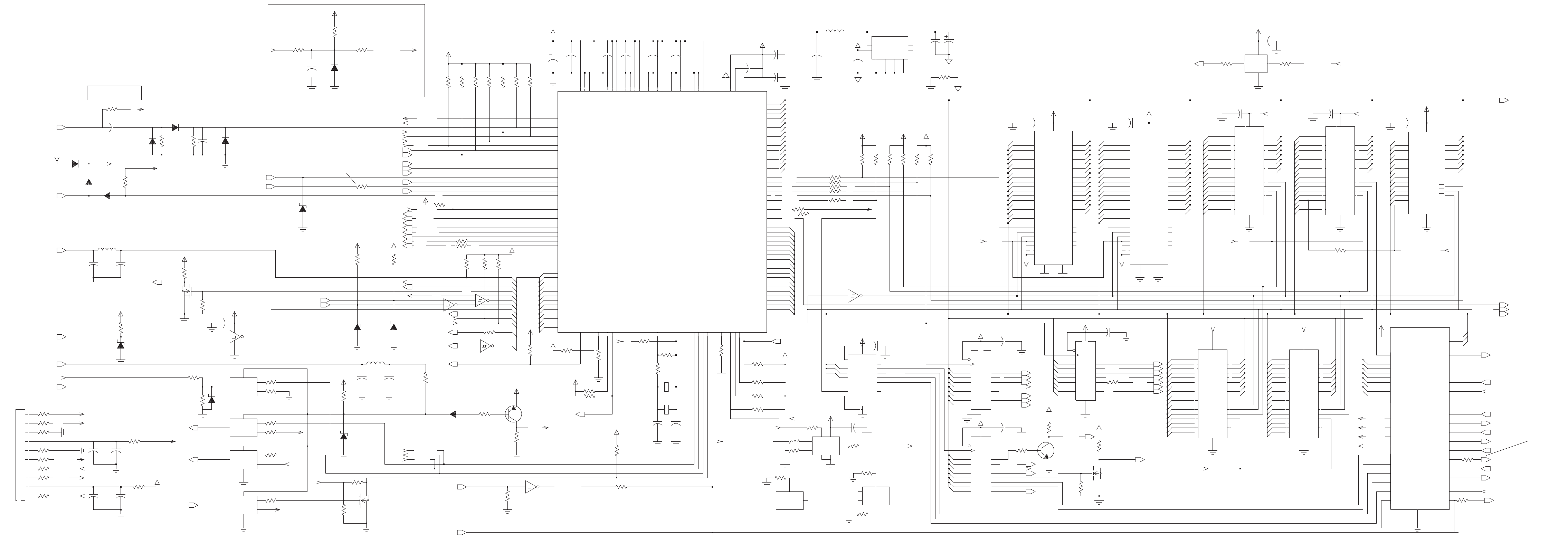
DSP CS
BDM DEBUG
DECODER
32KX8
FLASH 1
FLASH_1
256KX16
OPTION
FLASH_2
PORT 1
FLASH 2
EEPROM
SRAM
15
10
OPTION
SRAM
512KX8
FOR ANALOG INPUT FROM J5 PIN 39
256KX16
OMIT THIS WHEN USE ANALOG INPUT
20MHZ HC16R9497
ONLY ONE
ASSEMBLED
OPTION
EEPROM
PORT_1
SRAM
PORT_2
PORT_1
OPTION
20MHZHC16OPTION
512KX8
SRAM
39K
R5051
11
VCC
WR_
VCC
5
0
3
CSA_
CSB_
CSC_
CSD_
D10
D11
D12
D13
D14
D15
D8
D9
GND
INTA
INTB
INTC
INTD
RD_
RESET
RS232_TTL_SW
RXA
RXB
RXC
RXC_MODEM_TTL
RXD
SHDN1_
SHDN2_
TXA
TXB
TXC
TXC_MODEM_TTL
TXD
TSW-105-23-5-D
J9
10
9
1
2
3
4
5
6
7
8
UART_UNIT
A0
A1
A2
CLK
7
R5039
10M
39K
12
8
8
R5059
11
8
13
1000PF
C5021
3 4
15
14
VCC
1
13
11
74HC14
U5005
39K
R5004
14
13
15
14
VCC
R5101
10K
1
11
5.6V
VR5008
10UF
C6032
0
39K
R5048
C5008
0.1UF
15
7
4
13
9
0
R9616
R9709
8
4
VCC
39K
9
VCCVCC
10
0
R9708
12
VCC
14
11
R9623
14
39K
R9427
0
0.1UF
C5002
10
R9703
OPTION
R9696
0
10
0
R9695
R9694
0
5
5.6V
VR5007
R9702
2
39K
0
39K
R9710
10
8
9
R5021
8
2
1
11
C5006
0.01UF
OPTION
R9681
15
R9621
0
VCC
F
100
R5060
R9712
9
6
WE
8
10
8
OPTION
A6
3A7
25 A8
24 A9 20
CE
14
GND
11
I|O0 12
I|O1 13
I|O2 15
I|O3 16
I|O4 17
I|O5 18
I|O6 19
I|O7
22
OE
28
VCC
27
U6043
AT28C256_15SC
10 A0
9A1
21 A10
23 A11
2A12
26 A13
1A14
8A2
7A3
6A4
5A5
4
13
VCC
11
12
13
VCC
VCC
7
9
R9604
OPTION
39K
15
0BAS R5016
12
10
R5040
R5071
VCC
0
16
39K
7
15
13 Q5
16
Q6
19
Q7
VCC
20
1_MR
6
5
D3
13 D4
14 D5
D6
17
18 D7
10
GND
2
Q0
5
Q1
6
Q2
9
Q3
12
Q4
15
15
U6068
74VHC273
11 CP
3D0
4D1
7D2
8
13
8
VCC
4
L5002
22UH
0
12
13
F
10K
R5068
12
4700PF
C5022
9
R9624 0
13
5
9
14
13
12
6
5
9
MAX811MEUS-T 1
GND
3MR_
2RESET_
4
VCC
4
16
VCC
R9674
U5014
10
0
10
14
7
2
3
13
0
2
1
4.7K
R5052
1
3
2
CR5005
MMBD701LT
5 6
Q5005
3906L
3
15
74HC14
U5005
10
10
C9570
100PF
6
R5000
VR5001
5.6V
0
R5001
4.7K F
9
5
C5001
0.1UF
8
74HC14
U5005
9 8
18
1
R9620 0
VCC
R5014
4.7K
14
R5056
100
11
4
VCC
1
11
10
12
0
0.1UF
C5005
0.1UF
10
R5023
7
C5023
0BAS
VR5004
5.6V
R9677
6.8K
6
CL
9
CZ
4Z
5
Z0
3
Z1
2
14
U5007
HC4053-M_C
16
3
R5047
39K
15
14
CR5001
MMBD914T
14
7
R9554
0
10K
R5104
U5007
HC4053-M
10
CY
15Y
2
Y0
1
Y1
12
R9553
13
SW_A+
2
11
8
0
3904L
Q5004
12
3
2
18
13
C5016
0.1UF
0
R9618
VCC
R5067
200
VR5006
5.6V
3
2
OPTION
R9683
0
R9615
15
VCC
16
15
VCC
0.1UF
C5013
1_MR
39K
R5065
18 D7
10
GND
2
Q0
5
Q1
6
Q2
Q3 9
12
Q4
Q5 15
16
Q6
19
Q7
20
VCC
11 CP
3D0
D1
4
7D2
D3
8
13 D4
14 D5
17 D6
39K
12
U6070
74VHC273
10
17
VCC
R5063
8
WR_ 5
C5010
0.1UF
I|O0 21
I|O1 22
I|O2 23
I|O3 25
I|O4 26
I|O5 27
I|O6 28
I|O7 29
N.C. 9
OE_ 32
VCC
18
A3
17
A4
16
A5
15
A6
14
A7
13
A8
3
A9
2
CE1_ 30
CE2 6
GND
24
U6094
A0
20
A1
19
A10
31
A11
1
A12
12
4A13
A14
11
A15
7
A16
10
A2
C9572
3
IS62C1024AL
C5007
11
100PF
5.6V
VR5002
33UF
0.1UF
C9608
5
4
3
100NF
C6035
R9701
OPTION
R9693
0
10
8
0
R9692
15
0.1UF
C5028
13
12
10
5
39K
16
8
4
R9561
8
C5011
0.1UF
8
VCC
U5006
HC4053-M
10
CY
15Y
2
Y0
1
Y1
12
11
11
7
6
C9511
0.1UF
13
0.01UF
C6033
6
U5006
CL
6
CZ
9
Z
4
Z0 5
Z1 3
12
11
8
7
HC4053-M_C
1_MR
2
12
1
0
18 D7
10
GND
2
Q0
Q1 5
6
Q2
9
Q3
12
Q4
15
Q5
16
Q6
19
Q7
20
VCC
74VHC273
CP
11
3D0
4D1
7D2
8D3
13 D4
14 D5
17 D6
R5034
08
U6069
39K
R5002
2K
R5046
NC3
16
NC4
9
NC5
10
NC6
28 OE
12 RESET
37
VCC
11 WE
16
33
I|O2
35
I|O3
38
I|O4
40
I|O5
42
I|O6
44
I|O7
30
I|O8
32
I|O9
13 NC1
14 NC2
15
CE
27
GND
46
GND1
29
I|O0
31
I|O1
34
I|O10
36
I|O11
39
I|O12
41
I|O13
43
I|O14
45
I|O15|AA16
17 A17
23 A2
22 A3
21 A4
20 A5
19 A6
18 A7
8A8
7A9
47 BYTE
26
U5001
TE28F400B5B80
25 A0
24 A1
6A10
5A11
4A12
3A13
2A14
1A15
48
R9619
VCC
5
VCC
4
0
11
11
0
R9622
100K
R5009
C5009
0.1UF
11
R5043
VCC
15
14
0
39K
9
3
SW_A+
SW_A+
0
12
1
9
NC3
16
NC4
9
NC5
10
NC6
28 OE
12 RESET
37
VCC
11 WE
R9560
39K
I|O15|A
33
I|O2
35
I|O3
38
I|O4
40
I|O5
42
I|O6
44
I|O7
30
I|O8
32
I|O9
13 NC1
14 NC2
1526 CE
27
GND
46
GND1
29
I|O0
31
I|O1
34
I|O10
36
I|O11
39
I|O12
41
I|O13
43
I|O14
45
A16
17 A17
23 A2
22 A3
21 A4
20 A5
19 A6
18 A7
8A8
7A9
47 BYTE
U6035
TE28F400B5B80
25 A0
24 A1
6A10
5A11
4A12
3A13
2A14
1A15
48
5 12
74HC14
U5005
1 2
8
1
2
7
6
15
15
R9535
2K
CR5003
MMBD701LT
20PF
12
13
4
C5032
38.4KHZ
Y5000
14
OPTION
R9497
13
10K
R5066
R5050
4.7K
VIN
8
VOUT
1
4.7K
R5013
VRG78L05
U6021
GND
2 3
GND GND
6 7
GND
N.C 5
NC 4
R9552
0
12
22UH
L5000
1
0
12
14
R94930
VCC
6
6
OPTION
R9673
0
9
R9682
2
11
VCC
14
4
R9617 0
10
R5044
10K
2
4.7K
R9516
VSSE6
97
VSSE7
54
VSTBY
XFC60
55XTAL
R5005
39K
2
VSS2
105
VSS5
43
VSSA
22
VSSE
VSSE141
62
VSSE2
83
VSSE3
9
VSSE4
125
VSSE5
112
VDDE3
124
VDDE5
113
VDDE6
98
VDDE7
84
VDDE8
56
VDDSYN
VRH50
51
VRL
29
VSS
58
VSS1
82SIZ0|PE6
65TSTME_|TSC
18 TXD|PQS7
59
VDD1
1
VDD3
42
VDDA
21
VDDE
VDDE140
61
VDDE2
8
16 PCS3|PQS6
128 PWMA
127 PWMB
69RESET_
17 RXD
80
R|W_
12 SCK|PQS2
SIS1|PE7
81
3OC2|OC1|PGP4
132 OC3|OC1|PGP5
131 OC4|OC1|PGP6
129PA1
126PCLK
13 PCS0|SS_|PQS3
14 PCS1|PQS4
PCS2|PQS5
15
76 IRQ3_|PF3
75 IRQ4_|PF4
74 IRQ5_|PF5
73 IRQ6_|PF6
72 IRQ7_|PF7
10 MISO|PQS0
MODCLK|PF0
79
11 MOSI|PQS1
OC1|PGP3
4
7IC1|PGP0
6IC2|PGP1
5IC3|PGP2
130 IC4|OC5|OC1|PGP7
67IPIPE0|DSO
68IPIPE1|DSI
IRQ1_|PF1
78
77 IRQ2_|PF2
88DSACK1_|PE1
86 DS_|PE4
57EXTAL
111
FC0|CS3_|PC0
114
FC1|CS4_|PC1
115
FC2|CS5_|PC2
FREEZE|QUOT
64
70HALT_
106
DATA3
104
DATA4
103
DATA5
102
DATA6
101
DATA7
100
DATA8
99
DATA9
DSACK0_|PE0
89
108
DATA1
96
DATA10
95
DATA11
94
DATA12
93
DATA13
92
DATA14
91
DATA15
DATA2 107
71BERR_
118
BGACK_|CS2_
BG_|CS1_ 117
66BKPT_|DSCLK
116
BR_|CS0_
63 CLKOUT
110
CSBOOT_
DATA0 109
46 AN2|PADA2
47 AN3|PADA3
AN4|PADA4
48
49 AN5|PADA5
52 AN6|PADA6
53 AN7|PADA7
85 AS_|PE5
AVEC_|PE2
87
24
ADDR4
25
ADDR5
ADDR6 26
27
ADDR7
28
ADDR8
30
ADDR9
44 AN0|PADA0
AN1|PADA1
45
ADDR18
ADDR19|CS6_|PC3 119
20
ADDR2
120
ADDR20|CS7_|PC4
121
ADDR21|CS8_|PC5
122 ADDR22|CS9_|PC6
123 ADDR23|CS10_|ECLK
ADDR3 23
ADDR10
ADDR11 32
33
ADDR12
34
ADDR13
35
ADDR14
36
ADDR15
37
ADDR16
ADDR17 38
39
2
U5008A
68HC16
90
ADDR0
ADDR1 19
31
6
10K
R5100
C9606
0.1UF
39K
R5038
5
4
0.1UF
VCC
R5017
39K
C5017
0
17
11
S
14
8
1
16
Q5006
7002
D
G
R9680
10K
R5055
VCC
200
0R5025
0.1UF
C9557
R9706
0
10
0
R9707
9
0
R9705
R5027
150K
HC4053-M_C
U6099
CL
6
CZ
9
Z4
Z0
5
Z1
3
VCC
MMBD701LT
CR5000
3
6
5
1K
1
7
GND
13 12
14
VCC
R5024
7
74HC14
U5005
10
6
C5026
0.1UF
13
L5001
22UH
6
5
U5005
11 10
C9536
0.1UF
MMBD701LT
CR5002
2
74HC14
R5075
9
0
D
G
S
9
R5030
4.7K
WR_
17
F
7002
Q5003
22
I|O1
23
I|O2
25
I|O3
26
I|O4
27
I|O5
28
I|O6
29
I|O7
9
N.C.
32
OE_
8
VCC
5
A3
16 A4
15 A5
14 A6
13 A7
3A8
2A9
30
CE1_
6
CE2
24
GND
21
I|O0
20 A0
19 A1
31 A10
1A11
12 A12
A13
4
11 A14
7A15
10 A16
18 A2
17
9
11
0
U5009
CS18LV10245
5.6V
VR5005
R5003
0.1UF
C5004
39K
6
3
39K
R5006
39K
R5054
1
R5035
VCC
12
0
9
1
2K
U6099
HC4053-M_PWR
11
CX
8
GND
16
VCC
7
VEE
14
X
12 X0
13 X1
10
9
HC4053-M
U6099
CY
10
Y15
Y0
2
Y1
1
VCC
0
11
7
C9616
R9704
9
5
0.1UF
27
I|O6 28
I|O7 29
N.C. 9
OE_ 32
VCC
8
WR_ 5
9
13
A8
3
A9
2
CE1_ 30
CE2 6
GND
24
I|O0 21
I|O1 22
I|O2 23
I|O3 25
I|O4 26
I|O5
A12
12
4A13
A14
11
A15
7
A16
10
A2
18
A3
17
A4
16
A5
15
A6
14
A7
VCC
11
CS18LV10245
U5010
A0
20
A1
19
A10
31
A11
1
R5029
4.7K
Q9068
7002
D
G
S
C9571
100PF
10
R5072
39K
5.6V
VR5003
C5033
20PF
VCC
18
100PF
C9569
C5029
0.1UF
270K
R5042
4
7
39K
R5041
39K
9
8
7
R5007
C9609
C5000
100NF
38.4KHZ
Y5002
0.01UF
0R5070
MMBD701LT
CR5004
8
13
VCC
10
9
0.1UF
C9509
14
R5022
C5003
0.1UF
1K
I|O4
27
I|O5
28
I|O6
29
I|O7
9
N.C.
32
OE_
8
VCC
5
WR_
14
13 A7
3A8
2A9
30
CE1_
6
CE2
24
GND
21
I|O0
22
I|O1
23
I|O2
25
I|O3
26
A11
12 A12
A13
4
11 A14
7A15
10 A16
18 A2
17 A3
16 A4
15 A5
14 A6
3
U6095
IS62C1024AL
20 A0
19 A1
31 A10
1
39K
O_2
12
O_3
O_4 11
10
O_5
9
O_6
7
O_7
16
VCC
15
R9627
U6079
74VHC138
A01
2 A1
3 A2
4 E1_
5 E2_
6 E3
8
GND
15
O_0
O_1 14
13
4
3
2
15
VPP_WP
SELECT_EEPROM_MSB
HOST_ADD(0:18)
UARTCS_D
UART CS_C
UARTCS_B
UARTCS_A
PORT_2
HC16_SELECT_EEPROM_MSB
HC16_SELECT_EEPROM_MSB
4
VCC
U|D_
PA_MUTE
VBAT
HOST_DATA(0:15)
RESET
VBAT
DSP_RW
KW_TUNE
BDM_CLK
BDM_FREEZE
BDM_DSI
BDM_DSO
CLK
EX_RESET_MR_
KW_ALC
CLK_IN
VBAT
RESET
VBAT
AMP_ON_OFF
PA_INHIB
FAN_ON_OFF
KW_ON_OFF
SQ_GATE
BIT
BATT_CHK
CH_RST
CS_
INC_
TXB
TXA
RXD
RXC_MODEM_TTL
RXC
RXB
RXA
RS232_TTL_SW
RESET
UARTD_INT
UARTC_INT
UARTB_INT
UARTA_INT
UART_CL
ANAOLG_INPUT
TXC
ANAOLG_ INPUT
RESET
V_FWD_HF
V_REV_TUNE
UART_CL
RS232_TTL_SW
VPP_WP
VPP_WP
TXD
TXC_MODEM_TTL
TXC
UARTD_INT
TU_CUR_LIM
DSP_REQ
UARTC_INT
UARTA_INT
UARTB_INT
DSP_CS
BEER
BATT_SENSE
PWR_LEVEL
AMB_TEMP
V_REV_HF
PA_TEMP
V_FWD_PA
BDM_DSI
STOP_SCAN
SPI_CLK
PEND|OCXO_SEL
FRAC_N_2_SEL
FRAC_N_1_SEL
LOW_RF_SEL
MONITOR
SPI_DATA_OUT
EXT_AUDIO_SW
SPI_DATA_IN
BKPT_DSCK
FAN_ON_OFF
FREEZE
DSO
KW_TUNE
BEER
BDM_CLK
BDM_FREEZE
RESET
BDM_DSO
SELECT_EEPROM_MSB
I_O(0:12)
PTT_MIC
EX_RESET_MR_
VBAT
CLK
NOISE_CONTROL
VCO3_SEL
VCO2_SEL
VCO1_SEL
DSP_RESET
AUDIO_SW
AUDIO_C_P_SW
SQ_SW
VP_PTT
DSI
EX_RESET
BATT_CHK
KW_PTT
KW_ALC
KW_TUNE
BAT_IN
VPP
CH_RXD+
CH_TXD+
PTT_IN_DATA
PTT_IN_VOICE
PTT_IN_CW
KW_C_C
SYNTH_LOCK
PTT_OUT
TU_CH_CHNG
KW_C_C
D2A_OVEN_SEL
EXT_ALARM_CONT
A-13/A-14
MM-E2072-09333-00
Figure A-1.F.LORDModule,
SchematicCircuitDiagram
(Sheet6of15–HostCircuits)
OMIT THISWHENUSE ANALOGINPUT
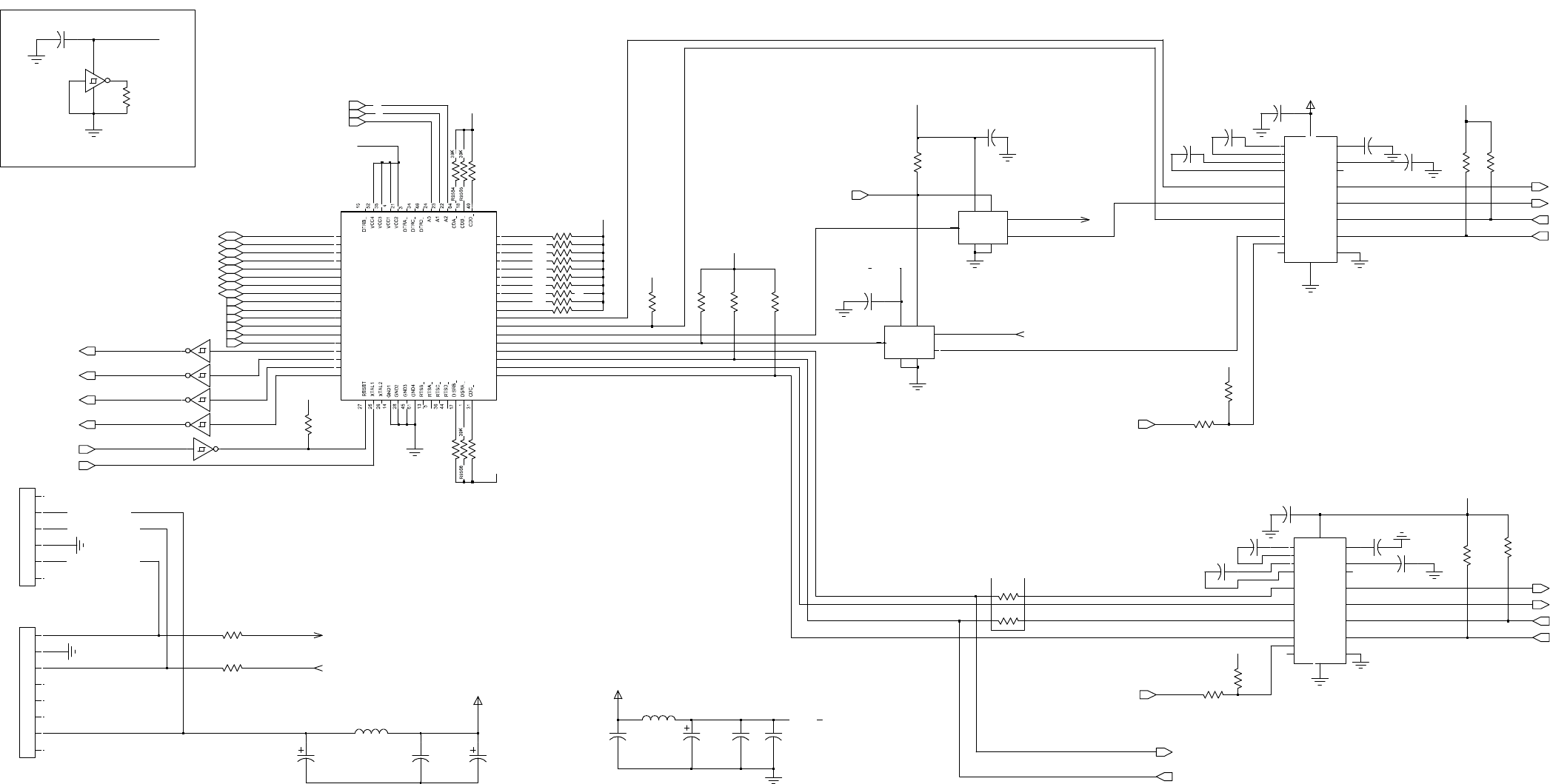
MM-E 2072-09333-00
V+
3
V-
7
V
CC
19
D
I
S
C
O
NNECT FOR
I
NTE
RN
AL
M
OD
EM
R
S232_SW
= LOW
G
P
S
MODE (J7)
N
O
R
M
A
L
P
T
P
CS
SPARE
R
S232_SW
= HIGH
N
.C 14
NC
11
R1
IN
16
R1OUT
15
R2
IN
9
R2OUT
10
S
HDN_
20
T
1
IN
13
T
1OUT 17
T
2
IN
12
T
2OUT
8
U6062
M
A
X
3222E
C1+
2
C1-
4
C2+
5
C2-
6
E
N_
1
GND
18
C
9520
1
UF
C
9519
C
9526
1
UF
0.1
UF
14
X
12
X0
13
X1
1
UF
C
9525
U
5006
H
C
4053-M_PWR
11
CX
8
G
ND
16
V
CC
7
VEE
0.1UF
C9607
R9520
39K
R9525
1
UF
C
9521
39K
C
9518
0.1
UF
0
R
9625
R
9626
0
R
5037
39K
9
8
R9523
U6080
74VHC14
R9522
39K
R9521 39K
39K
C
5025
0.1
UF
R
9502
39K
U6080
74VHC14
1 2
0.1
UF
C
5024
1
UF
74VHC14
U6080
5
6
C
9522
R9569
39K
R
9510
0
39K
39K
R9570
R9524
R9571
V
CC
R9608
39K
39K
R9567
39K
VCC
12
VCC
14
74VHC14
U6080
11
10
U6080
74VHC14
GND
7
13
R9526 39K
39K
R9575
R
9574
39K
39K
R9566
C
9524
0.1
UF
R
9501
39K
19
V
CC
R
9562
39K
R1
IN
15
R1OUT
9
R2
IN
10
R2OUT
20
S
HDN_
13
T
1
IN
17
T
1OUT
12
T
2
IN
8
T
2OUT
3
V+
7
V-
M
A
X
3222E
U6063
2
C1+
4
C1-
5
C2+
6
C2-
1
E
N_
18
GND
14
N
.C
11
NC
16
R
9500
39K
39K
R5053
1
UF
C
9527
3
4
R9572
39K
R9573
74VHC14
U6080
39K
39K
R
9563
C9605 C9610
0.01UF
10UF
22UH
L9084
39K
R
9503
13
X1
U
5007
H
C
4053-M_PWR
11
CX
8
G
ND
16
V
CC
7
VEE
14
X
12
X0
C
5027
0.1
UF
0.1
UF
C
9523
R9519 39K
R
9509
0.1UF
C9560
0
62
RXA
20
RXB
RXC 29
RXD 51
8
TXA
10
TXB
TXC 39
TXD 41
6INTA
12 INTB
INT C
37
INT D
43
40 IOR_
9IOW_ 63
RIA_ 19
RIB_
RIC_ 30
RID_ 50
D1
54
55 D2
56 D3
57 D4
58 D5
59 D6
60 D7
DSRC_ 32
DSRD_ 48
7CSA_
11 CSB_
CSC_
38
42 CSD_
2
CTSA_ 16
CTSB_
CTSC_ 33
CTSD_ 47
D0
53
5V_
UART
D8
5
V_UART
GPS CONNECTOR
0
J10
6
FTH_104_01_01_L_DV_P
1
2
3
4
5
6
7
8
J8
0
C9567
10UF
R9635
3.3V
7_188275_6
1
2
3
4
5
10UF
C9566
L9082
22UH
R9634
C9591
0.1UF
3.3VDC_FROM_LORD
GPS_TXD_TTL
GPS_RXD_TTL
TXD_A_FROM_GPS_TTL
RXD_A_FEOM_GPS_TTL
ST16C554
U6078
CSC_
CSD_
INTA
INT B
INT C
INT D
S
H
D
N
1_
S
H
D
N
2_
TXB
RXB
TXD
RXD
A0
A1
A2
CLK
5V_UART
5V_UART
5V_UART
5V_
UART
GPS_TXD_
TTL
RS232_TTL_SW
5V_UART
5V_UART
TX
C_
MO
DE
M_
TTL
RXC
_MODEM_
TTL
5V_UART
GPS_RXD_
TTL
5V_UART
RXA
TXA
5
V_
UA
RT
RXC
TXC
5
V_
UA
RT
5V_
UART
5V_
UART
5V_UART
RESET
D9
D10
D11
D12
D13
D14
D15
WR_
RD_
CSA_
CSB_
Figure A-1.G. LORD Module, Schematic Circuit Diagram (Sheet 7 of 15 – UARTs)
A-15/A-16
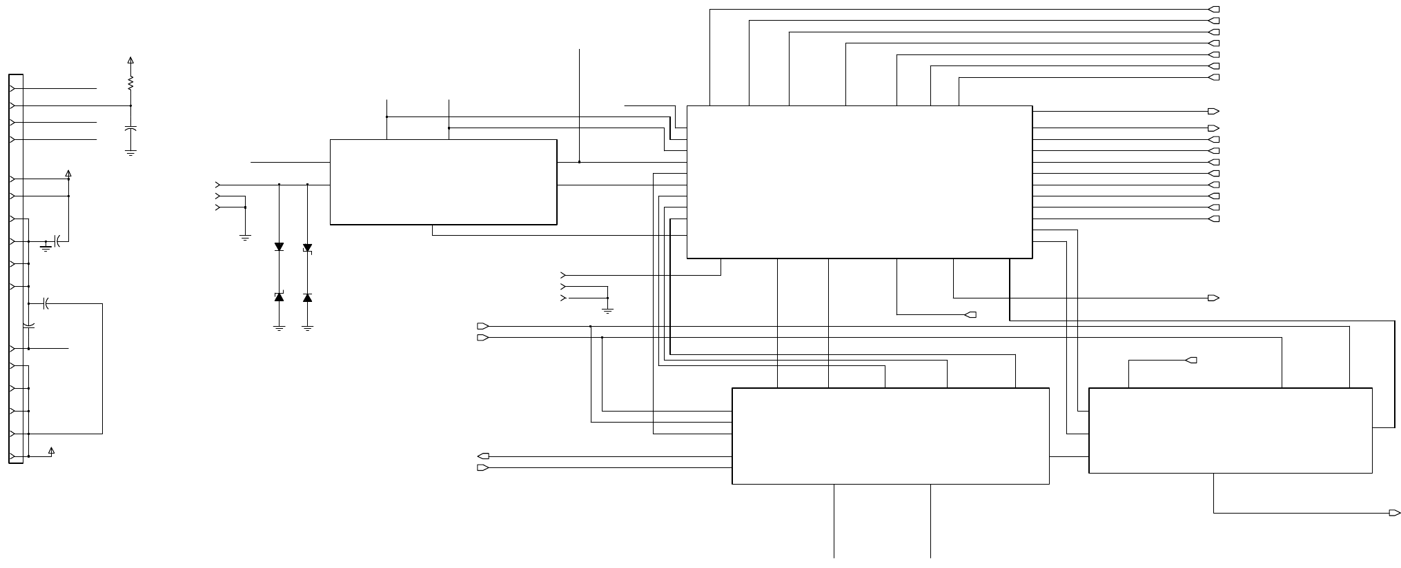
MM-E 2072-09333-00
J3
HIGH POWER
CONNECTOR
27
J1 GND
GND
3
30
GND
GND
GND
GND
34
32
36
10K
R3059
PRE_SELECTOR
LOW_RF_SEL
NOISE_CONTROL
PS_OUTRF_IN
SPI_CLKSPI_DATA_OUT
SPI_DATA_TO_HF
J1 RF_IN
1
100NF
F
I
LT_SP
I_CLK
F
I
LT_SP
I_DATA
F
I
LT_VC
O
1_SEL
F
I
LT_VC
O
2_SEL
F
I
LT_VC
O
3_SEL
F
I
RST
_INJ
PLL
_1_SEL
PLL_2_SEL
S
I
NE
_16.8
MHZ
SPI_
CLK
SPI_DATA _OUT
SYN
TH_LOCK
TX_SEC_
INJ
28
9T
C3048
9T 39
NOISE_CONTROL
OVEN_TE
M
P_CNTL1
OVEN_TE
M
P_CNTL2
PS_OUT
PTT_IN
P
W
R
_LEVEL
SPI_
CLK
SPI_DATA _OUT
SR_
CLK
SR_DATA
TO_HIGH_POWER
TX_SEC_
INJ
VCO
1_SEL
V
CO
2_SEL
V
CO
3_SEL
21
3.3V
A_D_DATA
B
I
AS_
OUT
CONVST
D
2
A
_
OVEN_SEL
DSM
_
AGC
_EN
DSM
_OU
TPUT_1.05
MHZ
DSP_16.8Mhz
F
I
LT_FRAC_N_1_SEL
F
I
LT_L OW_RF_SEL
F
I
LT_NOISE_CONTROL
F
I
LT_SP
I_CLK
F
I
LT_SP
I_DATA
F
I
LT_VC
O
1_SEL
F
I
LT_VC
O
2_SEL
F
I
LT_VC
O
3_SEL
F
I
RST
_INJ
FRAC_N_1_SEL
I
F_16.8Mhz
L
O
W
_
RF_SEL
3
SW_A+_RF
SW_A+_RF
SW_A+_RF
GND
J2
35
J3
40
C3046
100NF
C3047
100NF
C3045
100NF
VR5
ZENER_4813831A23
VR4
ZENER_4813831A23
CR2009
MMBD914T
CR2008
MMBD914T
19
I
F_16.8
Mhz
OVEN
_TEM
P_CNTL1
OVEN_TE
M
P_CNTL2
PENDULLU
M_SEL
I
NE
M
AMB
_TE
MP
S
_16.8
HZ
SP
I_
CLK
SP
I_
DATA
_OUT
2
38
OCXO_SW_A+
OCXO_SW_A+
OCXO_SW_A+
OCXO_SW_A+
OCXO_SW_A+
OCXO_SW_A+
25
J2
GND
23
12
2
37
TO_HIGH_POWER
J2
1
J1
D
2
A
_
OVEN_SEL
DSM
_OU
TPUT_1.05
Mhz
PENDULLU
M_SEL
D
I
G
I
TAL_16.8
Mhz
SPI_CLK
SPI_DATA _OUT
SYNTH_LOCK
FRAC_N_2_SEL
A
MB
_TE
MP
D
S
M
_
AGC
_EN
V
CO
3_SEL
V
CO
2_SEL
V
CO
1_SEL
NOISE_CONTROL
FILT _SPI_DATA
FILT_LOW_RF_SEL
BIAS_OUT
BIAS_OUT
BIAS_OUT
3.3V
A
_
D
_
DATA
SR_DATA
SR_
CLK
CONVST
PTT
_IN
P
W
R
_LEVEL
SPI_DATA _OUT_UP
SPI_
CLK
_UP
LOW_RF_SEL
F
RAC
_N_1_SEL
FILT_LOW_RF_SEL
FILT_LOW_RF_SEL
FILT_SPI_CLK
FILT_SPI_CLK
SPI_DATA_TO_HF
SPI_DATA_TO_HF
F
I
LT_SP
I_DATA
F
I
LT_SP
I_CLK
SPI_DATA_TO_HF
FILT _SPI_CLK
RF_CHAIN
SYNTHESIZER OVEN_CXO
Figure A-1.H. LORD Module, Schematic Circuit Diagram (Sheet 8 of 15 – RF Section Organization)
A-17/A-18
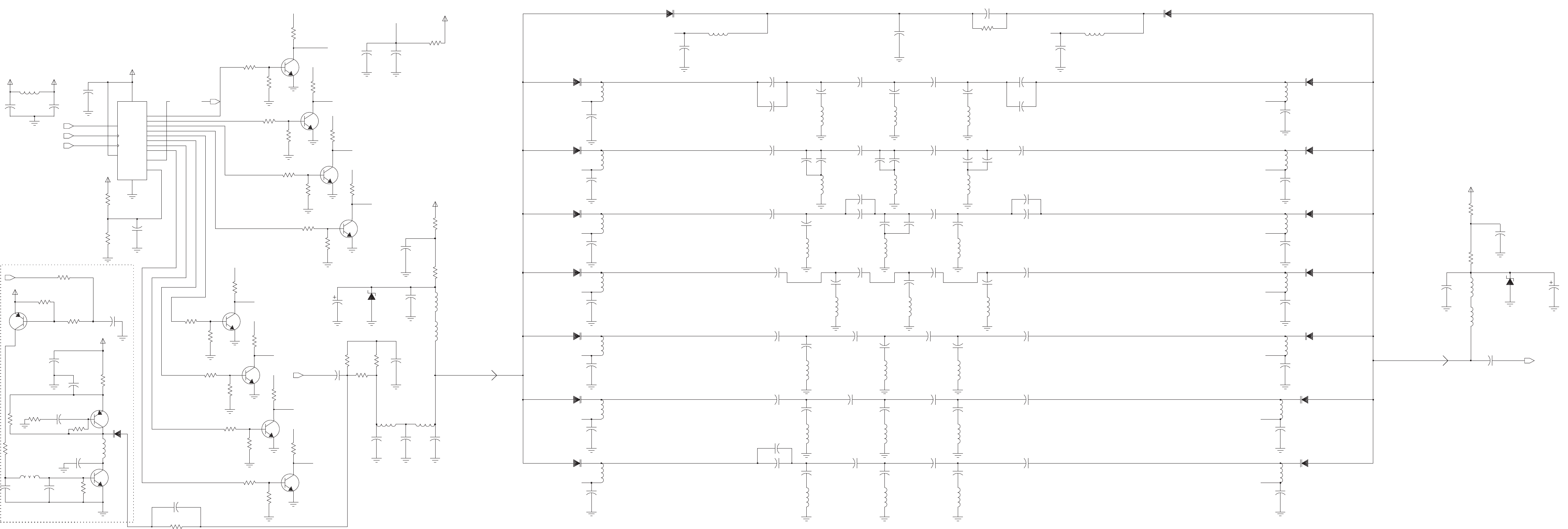
BIT NOISEGENERATOR
RX
CR16
MMBV3401
RX
R11
100K
C42
1500PF C26
0.1UF
1000PF
C111
C4
0.1UF
R37
1.2K
C18
0.1UF
L10
10UH
C51
620PF
R7
100K
C36
2.7NF
C58
6.8NF
9T
4700NH
L39
L51
22UH
L44
270NH
C12
0.1UF
C110
220PF
C72
270PF
R23
1.2K
C172
3904L
33PF
R1
100
VDD1
Q1
R2906
100K
VDD
1.2K
R30
C56
100NF
2.7NF
C34
C100
3.3NF
6800NH
L32
0.1UF
C13
C179
100PF
L13
10UH
100
R2
R17
6.8K
R9
100K
C160
100PF
C31
4700PF
C47
1000PF
L14
10UH
9V
L50
910NH
8.2UH
L25
3KR50
VR2
R29
1.2K
15
QA
1
QB
2
QC
3
QD
4
QE
5
QF
6
QG
7
QH
10 RESET
11 SHICLK
9
SQH
16
VCC
MMBZ5226BL
U1
74HC595A
14 A
8
GND
12 LATCLK
13
OUTEN
C54
470PF
C16
0.1UF
470PF
C99
C62
270PF
3.3UH
L16
390NH
L22
C10
0.1UF
0.1UF
C300
C87
0.1UF
0.01UF
C28
C102
2.7NF
C109
120PF
1.2K
R26
C2900
0.1UF
5600NH
L37
CR7
MMBV3401
C40
1.8NF
18
R2903
Q2901
3906L
120PF
C77
C8
0.1UF
470PF
C60
6.8K
R18
3904L
0.1UF
C11
Q7
Q5
3904L
MMBV3401
CR15
560
R80
L27
6800NH
100K
R6
1200NH
L43
C29
3.3NF
1200PF
C94
C91
0.1UF
22UH
L7
R3
100
100K
R10
MMBV3401
3.3UH
L54
C50
680PF
CR10
1.8NF
C38
0.1UF
0.1UF
C23
MMBV3401
C84
C22
0.1UF
CR3
0.1UF
C9
0.1UF
C25
L5
22UH
L29
6800NH
3.3NF
C130
180PF
C106
CR14
MMBV3401
L26
8.2UH
L46
MMBV3401
CR4
C65
180PF
22UH
R33
R60
18
220
C52
470PF
R2901
10K
0.01UF
C93
0.1UF
C17
C88
18PF
470PF
C96
C46
1000PF
R13
6.8K
R31
1.2K
10UH
L15
C85
0.1UF
L47
2.2UH
3904L
L52
22UH
270PF
VDD_PS
Q6
C104
6800NH
L31
L36
6800NH
MMBV3401
CR8
6.8K
R20
C92
0.01UF
22UH
L4
R15
6.8K
L42
1200NH
R25
1.2K
2.7NF
C82
0.1UF
C15
C14
0.1UF
0.1UF
C21
MMBV3401
CR6
680NH
L3
0.1UF
C83
68PF
C67
R32
10
910NH
L1
910NH
L2
0.1UF
C89
6.8K
R36
1.8NF
C37
10UH
L12
L38
5600NH
R21
6.8K
R82
10
9V
680PF
C49
C44
1200PF
C61
470PF
C27
0.01UF
L48
2.2UH
C97
470PF
0.01UF
C81
C48
680PF
0.1UF
C112
6800NH
Q2
3904L
L35
6.8K
R35
0.1UF
C86
C43
1500PF
R34
470
6.8K
R16
2.7NF
C101
3904L
270NH
L45
Q8
CR17
MMBV3401
270PF
C105
390PF
C107
R81
560
C108
390PF
C20
0.1UF
VDD_PS
1.2K
R24
R27
1.2K
0.1UF
C7
680PF
C79
100K
R12
6.8K
R14
22UH
L6
3.3NF
C129
L20
C1
33UF
1.5UH
C6
0.1UF
L53
3.3UH
6800NH
L33
C90
0.1UF
L34
6800NH
C3
15UF
L28
6800NH
33UF
C2
MMBV3401
CR13
1
3
2
CR11
MMBV3401
MMBV3401
3906L
Q30
MMBV3401
CR1
CR2
L49
9V
C30
3.3NF
2.2UH
C95
470PF
MMBZ5226BL
MMBV3401
CR12
3904L
VR1
R19
6.8K
Q4
C24
0.1UF
270PF
C103
SW_A+_RF
6800NH
L30
C39
1.8NF
1.8NF
C41
6.8K
R22
0.1UF
C19
Q3
3904L
C98
470PF
MMBV3401
CR9
C78
120PF
220PF
C80C45
1000PF
C66
68PF
10UH
L9
C200
0.1UF
R5
100K
Q9
1
3
2
22UH
L55
3904L
100K
R8
1.2K
R28
22UH
L8
CR5
MMBV3401
NOISE_CONTROL
100
R4
PS_OUT
FL0
13V
FL1
FL0
FL5
LOW_RF_SEL
SPI_CLK
SPI_DATA_OUT
SPI_DATA_TO_HF
RF_IN
FL2
13V
13V
FL0
13V
FL7
FL1
13V
FL5
FL4
FL3
FL2
FL1
FL7
FL6
13V
13V
FL6
13V
FL5
FL7
FL6
FL4
FL3
FL2
FL4
13V
FL3
A-19/A-20
MM-E2072-09333-00
Figure A-1.I.LORDModule,SchematicCircuitDiagram
(Sheet9of15–PreselectorCircuits)
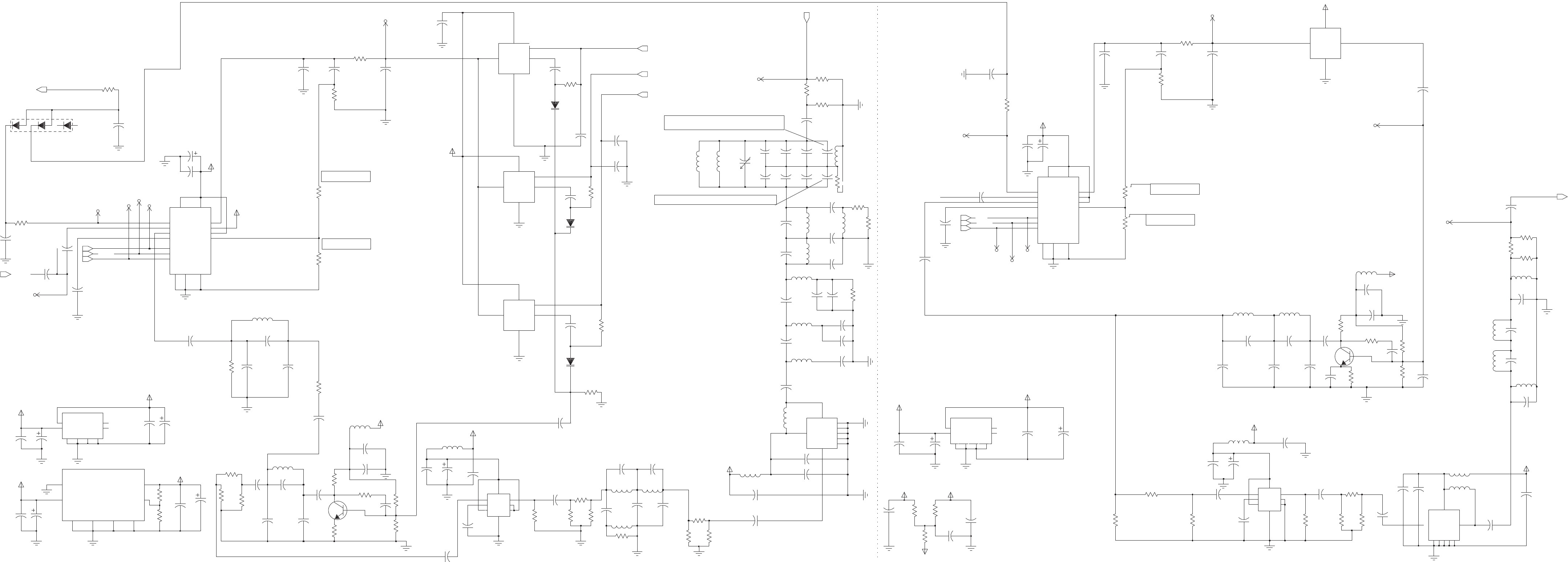
OPTIONAL ADF4110
OP TI O N A L L M X2316
OP TI O N A L A DF 4110
SECONDSECTION
FIRST SECTION
NP- C2150
NP- C2131
NP- C2130
51
SHOULDBE330PF(1206)FORBSFOPERATION
SHOULDBE47PF(1206)FORBSFOPERATION
NP- L2014
NP- L2015
NP- L2016
NP- C2126
NP- C2128
NP- C2127
NP- C2129
OPTIONAL LMX2316 NP - R2076
C2063
1000PF
R2034
R2011
L2006
100NH
OP TI ON
11 PF
C2123
C2084
0.1UF
R2044
3.3K
0.1UF
C2071
20PF
18
R2080
C2105
0.1UF
C2222
C2061
C2040
100PF
1000PF
56
68PF
C2042
CR2000
TRIPLE_DIODE
321 4
R2053
1K
0.1UF
R2067
300
10UH
C2091
SYN1_LE
L2018
15UF
C2009
SYN2_LD
150
R2037
R2003
0
390
R2061
0.1UF
C2078
GND
N.C 5
NC 4
VIN
8
VOUT
1
VRG78L05
U6025
GND
2 3
GND
6
GND
7
0.1UF
C2116
R2022
8.2K
C2021
0.1UF
0.1UF
C2073
OPTION
C2129
R2045
9.09K
C2117
100NF
18
0.1UF
C2081
R2078
VCO3
CTRL FN
GND
SW
VCC
C2045
L2013
68NH
11PF
C2085
0.1UF
L2012
C2064
1000PF
68NH
R2036
150
10
R2017
SYN2_VCO_OUT
R2043
3.3K
VDD
100PF
C2039
C2018
0.1UF
SYN1_D
4.7UF
C2007
R2071
300
C2141
15PF
0
R2002
R2085
10
VP1
R2007
OPTION
1K
R2055
20PF
C2052
120NH
L2014
VCAP
C2150
C2106
SW_A+_RF
0.1UF
C2024
C2134
39PF
0.1UF
15PF
82NH
L2026
C2056
35.5NH
L2015
SYN2_D
C2121
3.9NF
MMBV3401
CR2001
R2079
18
L2009
VP1
C2093
0.1UF
100NH
R2008
4.7K
C2086
0.1UF
VOS
510
R2038
C2125
5.6PF
C2142
3.9NF
75PF
C2017
C2054
20PF
0.1UF
C2076
0.1UF
C2089
R2004
0
VDD1
SYN1_CONTROL
VCO4
CTRL FN
GND
VCC
OPTION
C2128
C2077
0.1UF
C2013
7.5PF
C2047
4.7UF
39PF
C2136
L2019
10UH
R2070
300
C2008
4.7UF
C2138
18PF
C2087
0.1UF
11PF
SYN1_CLK
5
4
NC
NC
8VIN
1VOUT
VOS2
C2046
U6024
VRG78L05
2
GNDGND GNDGND
367
C2111
0.1UF
VDD2
R2082
18
51PF
C2044
C2110
OPTION
C2126
C2095
0.1UF
0.1UF
18PF
C2139
4.75K
R2047
VOS2
C2092
VOS
0.1UF
VDD2
5.62K
R2046
R2052
7.5K
C2002
1.0UH
L2024
C2049
4.7UF
OPTION
C2130
100NF
C2114
0.1UF
C2079
0.1UF
L2002
51
R2035
C2019
0.1UF
270NH
C2051
C2118
33PF
SYN1_16.8MHZ
1.5NF
C2016
75PF
VDD1
VDD1
R2065
300
C3111
0.1UF
C2010
15UF
C2025
0.1UF
15
VP 16
CE 10
CPO 2
CLOCK
11
DATA
12
FLO 1
FIN
6
FIN_
5
FO_LD
14
GND1
3
GND2
4
GND3
9
LE
13
OSC_IN
8
VCC1
7
VCC2
OPTION
R2076
U6075
ADF4110
680PF
C2070
L2007
100NH
20PF
C2055
R2012
4 .7K
1K
R2050
27
R2029
10
R2084
1K
R2056
SW_A+_RF
300
R2066
100NF
C2048
L2008
OPTION
C2127
OPTION
C2131
100NH
R2058
560
0.1UF
1K
R2051
C2031
0.1UF
C2080
0.1UF
C2112
MMBV3401
CR2003
C2097
0.1UF
C2006
4.7UF
C2003
SB
6
SW1
3
SW2
2
VCC
4.7UF
MC12093DR2
U2002
5
GND
1IN
8IN_
4
OUT
7
VDD1
SYN1_LD
C2088
5.6PF
C2124 C2096
0.1UF
8.2NH
L2005
0.1UF
O.PUT-INH
5
OUTPUT
1
U2004
LM2931CD
ADJUST
4
2
GND
3
GND
6
GND
7
GND
INPUT
8
18
R2083
SYN2_CLK
R2064
300
MMBV3401
CR2002
6.8NF
C2146
SW_A+_RF
C2050
33PF
VDD2
MMBR951
Q2007
C2036
270NH
L2003
0.1UF
4.3PF
VCO2
CTRL FN
GND
SW
VCC
C2072
0.1UF
C2030
R2074
220
SYN2_LE
C2043
51PF
15PF
C2057
10
10UH
L2020
R3301
C2075
0.1UF
R2057
560
VCO1
CTRL FN
GND
SW
VCC
0.1UF
VDD1
C2032
0.1
C2000
C2015
75PF
2
GND
GND
3
GND
4
GND
6
GND
7
1IN5
OUT
8
VCC
U2009
PC1678GV
20PF
0.1UF
C2083
L2017
10UH
C2053
0.1UF
C2090
1K
R2048
270NH
L2004
GND2
4
GND3
9
LE
13
OSC_IN
8
VCC1
7
VCC2
15
VP 16
U6076
ADF4110
CE 10
CPO 2
CLOCK
11
DATA
12
FLO 1
FIN
6
FIN_
5
FO_LD
14
GND1
3
SYN1_RF_TO_MIXER
L2016
100NF
C2120
270
R2000
35.5NH
1000PF
C2062
L2000
33NH
C2035
Q2006
MMBR951
R2026
12PF
0.1UF
130
R2009
C2109
33K
C2014
15UF
C2094
0.1UF
C2067
1000PF
R2049
1K
C2133
39PF
0.1UF
C2020
15NH
L2011
16.8MHZ
SPI_CLK
PLL_1_SEL
FILT_SPI_CLK
FILT _SPI_DATA
PLL_2_SEL
SPI_DATA_OUT
SYN2_CONTROL
SINE_16.8MHZ
FILT _VCO1_SEL
SYNTH_LOCK
FIRST_INJ
FILT _VCO3_SEL
FILT _VCO2_SEL
IN
8IN_
4
OUT
7SB
6
SW1
3
SW2
2
VCC
MC12093DR2
U2003
5
GND
1
10
R2086
C2098
0.1UF
300
R2068
18
R2081
300
R2069
0.1UF
C2099
C2004
4.7UF
C2101
0.1UF
10UH
L2021
1K
R2054
VDD2
R2059
560
0.1UF
C2100
R2060
560
C2107
0.1UF
8
VCC
U2010
PC1678GV
$V
2
GND
GND
3
GND
4
GND
6
GND
7
1IN 5
OUT
VDD2
120NH
L2027
C2038
100PF
L2025
1.0UH
C2074
0.1UF
C2137
39PF
L2023
120NH
0.1UF
C2104
300
R2063
C2041
68PF
0.1UF
C2102
SYN2_RF_TO_MIXER
120NH
L2028
C2037
100PF
1200NH
L2001
C2108
0.1UF
300
R2062
18
R2077
10UH
L2022
C2140
15PF
C2103
0.1UF
TX_SEC_INJ
16.8MHZ
A-21/A-22
MM-E2072-09333-00
Figure A-1.J.LORDModule,
SchematicCircuitDiagram
(Sheet10of15–SynthesizerCircuits)
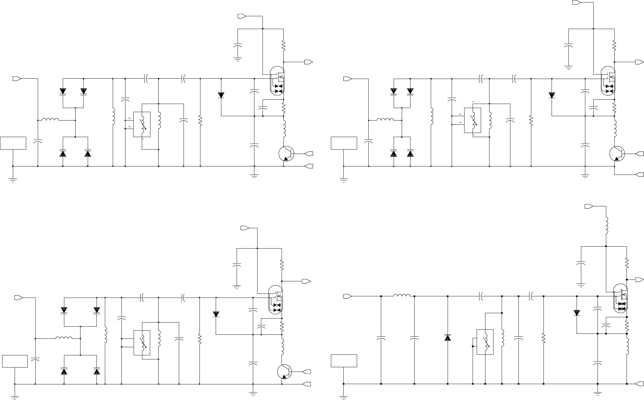
MM-E 2072-09333-00
CR9000
BB659C-E7902
C9093
L9076A
66 .8NH
CR9076
BB659C-E7902
10PF
L9079
18
R
9100
1.5UH
B
F992
Q
9000
D
2
G1
4
G2
3
S
1
Q
9065
M
UN
2211
T1
180PF
C
9110
1
.
5
UH
MMBD
701 LT
L
9077
1000PF
C
R
9068
L
9076
35 .5NH
C
9099
1
C9000
1000PF
CR9069
BB659C-E7902
SH9000
SHIELD
CR9075
BB659C-E7902
R
9000
27K
R
9065
200
C
9094
15PF
C
9095
C9098
12PF
47PF
C
9096
390PF
10PF
C
9097
FN
VCC
CTRL
SW
G
ND
1.5UH
L9000
1000PF
C
9089
27K
R
9020
C9020
C9062
OP TI ON
C
R
9063
1000PF
L
9070
MMBD
701 LT
C
9200
1000PF
1
.
5
UH
M
UN
2211
T1
Q
9063
BB659C-E7902
1.5 UH
L9020
1.5UH
CR9079
R
9200
10
L9072
66 .8NH
35 .5NH
L9065A
BB659C-E7902
CR9020
L
9065
15PF
C
9066
BB659C-E7902
CR9066
5
.
1PF
BB659C-E7902
CR9071
C9084
100PF
C
9063
C
9074
43PF
C
9069
12PF
SH9020
1
Q
9020
B
F992
2
D
4
G1
3
G2
1
S
SHIELD
FN
VCC
CTRL
SW
G
ND
200
R
9063
a. VCO 1 b. VCO 2
53 NH
L9066A
2
4
3
1
NP - C9079
180
PF
C
9300
L
9074
M
UN
2211
T1
Q
9064
CR
9064
1
.
5
UH
BB659C-E7902
CR9074
MM
BD
701
LT
1000 PF
C
9091
27K
R
9040
12
PF
CR9040
BB659C-E7902
L
9066
C
9067
R
9064
28NH
CR9073
BB659C-E7902
200
1
CR9067
BB659C-E7902
Q
9040
B
F
992
2
D
4
G1
3
G2
1
S
SHIELD
SH9040
C9040
C9079
1000 PF
1.5UH
OP TION
C
9070
12
PF
L9040
C9072
100 PF
C
9075
33 PF
L9073
1.5UH
C
9078
3
.
3
PF
FN
VCC
CTRL
SW
G
ND
18
R
9300
3
S
1
R
9400
10
NP-CR 9062
B
F992
Q
9060
D
2
G1
4
G2
C
9082
30PF
8
NH
CR9062
MMBD701LT
1000PF
L
9064
C
9087
1000PF
C9060
1PF
C
9081
7
.
5PF
C
9061
5
.
6PF
R
9062
200
C
9076
R
9060
27K
2
4
3
1
SH9060
SHIELD
1
C9071
28 NH 28NH
L9064A
C
9400
1000PF
15PF
1SV229
CR9078
L9060
910 NH
C9080
3 . 3 PF
L
9062
910
NH
FN
CTRL
VCC
G
ND
L
9061
910
NH
c. VCO 3 d. VCO 4
Figure A-1.K. LORD Module, Schematic Circuit Diagram (Sheet 11 of 15 – VCO Circuits)
A-23/A-24
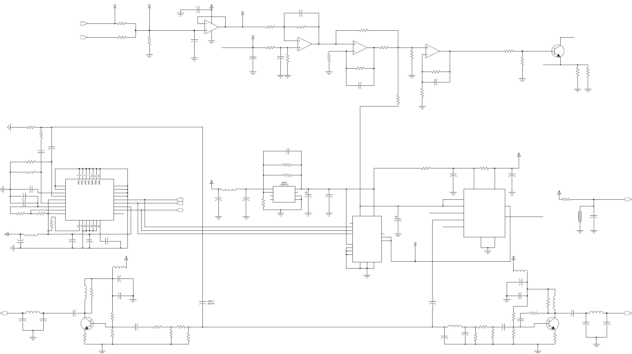
MM-E 2072-09333-00
NP
-
U3002
NP-U3010
U3010
AD7243BR
R3300
51
33K
R3044
1.5UH
L3000
39PF
C3025
150K
R3029
10K
R3330
33K
0.01UF R3043
C3011
10K
R3942
1
.0
U3000
MC33174
2
3
1
R3024
R3009
470
O
CX
O
_S
W_
A+
TEMP_SENSE
5V_TAP
6
FDBK
7
GND 4
IN
8OUT 1
SENSE 2
SHDN 3
5_ERROR
TEMP_CONT
C3037
R3063
33K
0.1UF
CUR_SENS
3
7
G
ND
4
10
G
ND
D2
A
_FREQ
HE
AT
_C
O
NT
5
O
CX
O
_RF_
OUT
2
O
CX
O
_S
W_
A+
RE
G
_S
W_
A+
11
T
E
M
P_SENS
8
6
9
V_REF_OUT
V_REF_OUT
U3002
HYBR_11P
R3075
150K
C3005
0.1UF
C3900
33UF
L3002
10UH
0.1UF
10UH
C3003
0
.
01UF
L3004
C3031
R3004
150K
U3000
MC33174_PWR
13
12
14
4
11
M
C33174
U3000
9
10
8
C3015
0
.
01UF
10M
R3600
R3060
10K
R3046
1K
R3020
10
33K
FREQ_CONT
R3006
C3019
68PF
R3025
1
.0
10K
R3350
3.3K
R3010
4
.
7UF
C3500
1K
R3013
0.1UF
C3002
VDD
130
R3019
R3076
10.0K
10UH
L3003
180PF
C3021
R3016
560
0
.
01UF
C3013
150K
R3050
0.01UF
C9401
C3075
0.01UF
R3017
560
C3012
0.01UF
C3014
0.01UF
0
.
01UF
OCXO_SW_A+
C3038
10M
R3310
TEMP_CONT_IN
MMBR951
Q3001
6
11
7
VDD
16
14
VSS
15
Q
3000
3904L
A
G
ND
12
4
3
10
D
G
ND
8
9
RE
FIN
1
2
V
O
UT
REFOUT
R
O
FS 13
S
DI
SDO
S
Y
NC_
B
I
N_|COMP
C
L
R_
DCEN
L
D
A
C_
SCLK
5
10K
R3062
0
.
01UF
0
.
01UF
C3016
C3028
U3000
M
C33174
6
5
7
R3021
10
R3034
62K
R3048
100K
R3064
10K
100
D2A_TEMP_CONT
0.01UF
9V
R3047
C3029
0.01UF
C3027
3
.
3K
R3051
L3006
10UH
C3044
39PF
C3035
1
.
5UH
L3007
0
.
1UF
10
R3058
1K
R3053
R3052
3
.
3K
0
.
1UF
C3036
0
.
1UF
C3034
R3056
560
10
R3057
C3033
0
.
1UF
VDD
MM
BR951
Q
3002
68PF
C3041
560
R3054
180PF
C3042
560
R3055
180PF
C3043
C3040
68PF
10UH
L3005
L3008
1
.
5UH
SINE_16.8MHZ
IF_16.8MHZ
OVEN_TEMP_CNTL2
OVEN_TEMP_CNTL1
NP-C3009
NP-R3011
NP-R3014
NP-R3026
NP-R3028
NP-R3032
OPTION
R3026
21
S0
BANDGAP-REF
25
S1
22
SCK
8SINE_OUT
24
SS
VDD
13
12
V_OPT
11
V_REG
GND
GND
26
NC
NC
NC
NC
NC
NC
NC
27
U3001
PENDUL_168MHZ
23
CE
7
C_EXT
9
DE
10 FO_SQW
29
28
GND
GND
6
5
33PF
C3023
10UH
L3001
C3007
C3006
0.1UF
0.1UF
OPTION
R3011
0.1UF
C3010
0.1UF
C3026
C3024
33PF
R3032
OPTION
150K
R3031
R3027
0
0.1UF
C3008 C3110
0.1UF
OPTION
R3014
VDD
OPTION
C3009
OPTION
R3028
SPI_DATA_OUT
SPI_CLK
PENDULLUM_SEL
TEMP_SENSE
HEAT_CONT
TEMP_SENSE
CU
R
_SENSE
VCC
6
.
8K
R3000
0
.
01UF
C3000
50K
R3023
A
M
B_
TE
MP
CUR_SENSE
HEAT_CONT
GND
1
Figure A-1.L. LORD Module, Schematic Circuit Diagram (Sheet 12 of 15 – Frequency Reference Circuits)
A-25/A-26
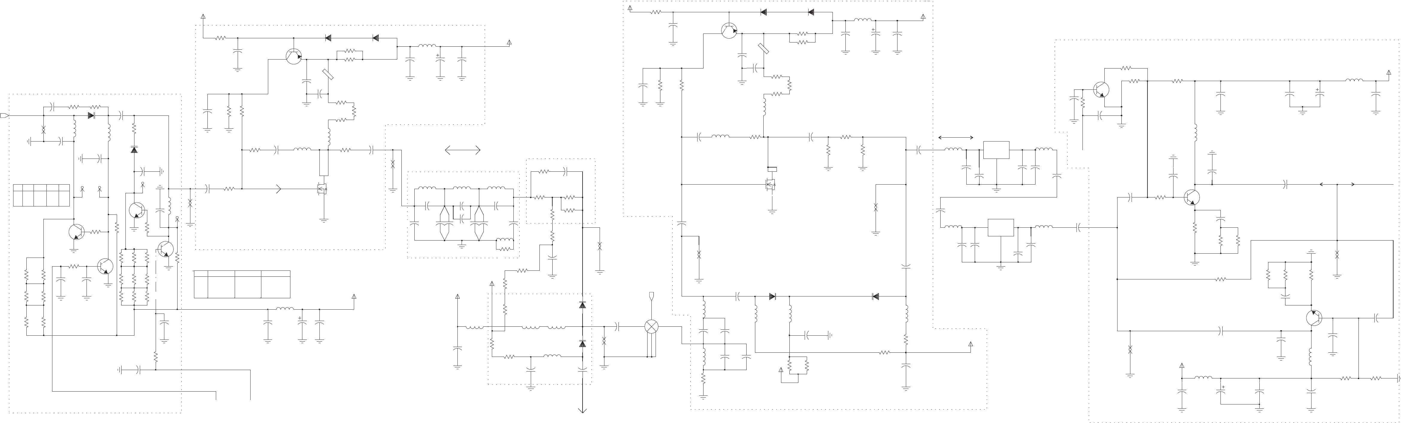
0DB 8V8V
8V
8V
8V
AMPLIFIER#1
9DBPAD
20DB 550
RX
RX,TX
ATTN STEP_AGC_30STEP_AGC_20STEP_AGC_10
RAGC
NP-C1033
NP-C1056
NP-C1057
20DB 0V
0V
0V
0V
0V
LPF#0
NP-C1032
ATT1+ ATT1- ATT2-ATT2+
AMPLIFIER#0
ATTN
TX
10DB
FET_MMFT6661T1
Q1002
D
G
S
RX,TX
BIDIRECTIONAL AMPLIFIER#2
30DB 555
SELECTOR#0
0DB 000
10DB 500
RX,TX
C1067
10NF
10NF
C1077
C1062
10NF
0.1UF
C1034
C1037
0.1UF
C1027
0.1UF
C1060
10NF
R1073
3K
10
R1010
IF2_3
AMP_3
0.1UF
C1028 CR1008
MMBV3401
Q1015
3904L
Q1011
3906L
2
150
R1048
G
S
3904L
Q1019
1
3
0.1UF
FET_MMFT6661T1
Q1001
D
C1009
0.1UF
C1000
100NF
C1080
100NF
C1072
39PF
C1035
FERRITE_BID
E1001
9V
R1034
18
9T
CR1005
MMBD914T
270NH
L1016
R1076
270
270
R1044
R1070
270
330
R1027
470
MMBD914T
CR1002
R1060
R1043
270
R1016
100
270
R1071
68
R1035
10K
R1042 0.1UF
C1048
OPTION
C1057
C1033
OPTION
27PF
C1054
C1056
OPTION
22PF
C1029
0.1UF
C1058
OPTION
C1032
0.1UF
C1078
0.1UF
C1002
0.1UF
33UF
C1003
C1001
270
R1075
0.1UF
C1023
560
R1049
L1000
22UH
LPF_1
910NH
L1012
560NH
L1048
MMBV3401
CR1009
R1028
330
2.7K
R1018
68
R1006
R1017
100
10
R1041
18
R1001
3904L
Q1014
9R
R1013
470 22UH
L1030
0.1UF
C1006
C1024
0.1UF
C1018
10NF
C1010
0.1UF
0.1UF
C1068
33UF
C1066
0.1UF
C1025
0.1UF
C1004
C1065
0.1UF
0.1UF
C1017
ATT2+
22UH
L1033
9T
270
R1068
9R
2.7K
R1074
18
L1020
22UH
R1032
22
9T
R1023
R1077
51
L1047
560NH
R1021
10
C1084
33UF
C1082
0.1UF
0.1UF
C1083
0.1UF
C1073
C1064
0.1UF
C1063
C1050
24PF
0.1UF
R1072
10K
MMBV3401
CR1012
R1065
150
9R
L1052
10UH
R1008
9V
R1029
270
10
E1002
FERRITE_BID
PS_OUT
R1055
10
Q1006
MMBR951
Q1003
MMBR951
9V
51
R1059
82NH
L1050
R1050
560
R1061
2K
R1019
470
45.100M
FL1
2
1
22
R1039
R1037
51
R1047
51
C1019
51
R1088
C1016
10NF
GND1
2 3 6
IF
5
LO 1
RF
4
10NF
C1021
RMS-1LH
U1000
0.1UF
C1014
0.1UF
C1015
33UF
C1013
0.1UF
C1036
0.1UF
C1044
0.1UF
0.1UF
C1012
C1041
0.1UF
C1055
24PF
C1030
22PF
R1062
270
10UH
L1043
AMP_2
C1042
9T
2K
R1012
0.1UF
R1058
330
R1000
10K
22UH
L1023
22UH
L1059
560NH
L1045
0.1UF
C1020
0
R1066
L1028
22UH
18
R1003
2.7PF
C1162
2.7PF
C1081
C1163
390
R1064
0.1UF
C1161
2.7PF
10
R1031 270NH
L1006
560NH
10UH
L1041
L1046
330
R1024
10
CR1011
$MMBV3401
$MMBV3401
R1007
CR1000
270
R1052
R1026
10
390
R1045
10
R1005
22UH
L1018
10
R1056
10NF
C1031
390
R1053
AMP_1
C1160
2.7PF
R1040
10
270
R1051
0.1UF
33PF
C1045
C1040
24PF
C1079
C1049
100PF
C1007
0.1UF
20PF
C1039
C1053
100PF
C1074
0.1UF
C1008
33UF
24PF
C1038
68PF
C1047
10
R1015
10
R1022
Q1000
3904L
10
R1014
ATT1+
L1042
10UH
L1054
10UH
L1017
22UH
R1020
2K
L1022
22UH
C1059 AMP_4
FL2
45.100M
2
1
0.1UF
C1026
10NF
11 PF
C1071
C1051
C1076
33PF
C1052
24PF
2K
R1009
24PF
R1036
2.7K
270
R1069
270
R1063
ATT2
R1038
10K
10NF
18
R1025
MIX_1
C1043
R1046
XTAL_OUT
0
R1067
2.7K
10UH
L1044
C1046
10NF
270NH
L1007
22UH
L1027
Q1013
3904L
R1011
2K
L1049
560NH
51
R1030
0.1UF
C1005
C1075
120PF
0.1UF
C1061
C1070
11 PF
0.1UF
C1022
22UH
L1021
9T
L1057
270NH
0.1UF
C1069
10NF
C1011
2.7K
270NH
L1008
R1054
ATT1
CR1010
MMBV3401
CR1007
MMBD914T
150
R1057
3906L
Q1007
22UH
L1029
R1002
CR1006
10K
R1033
68
MMBD914T
FIRST_INJ
TO_EXCITER
TRANS_IF
PS_OUT
STEP_AGC_10 STEP_AGC_20
STEP_AGC_30
A-27/A-28
MM-E2072-09333-00
Figure A-1.M.LORDModule,SchematicCircuitDiagram(Sheet13of15–FrontEndCircuits)
0V8V
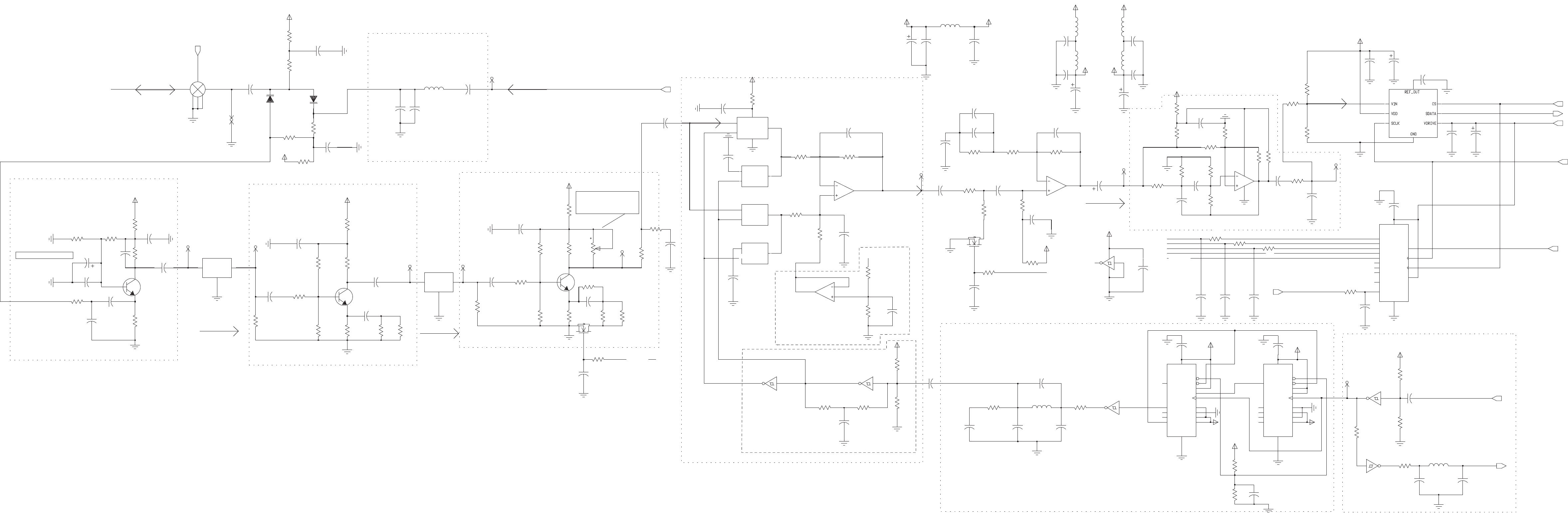
RX
RX
RX
TX AF_AMP
DUTYCYCLEEQUALYZER
AMP #33
TX 1.05MHZ BANDPASSFILTER
2.5 V REF
CONSIDERREMOVINGTHIS ECAP
AMP #32
ACTIVE_LPF
ALLOVERTHE RXCHAIN
39_DIVIDER
AMP #31
10 DB GAIN VERIATIONS
450K
FL3
GND
3
IN
1
OUT
THIS TRIMMERSHOULD COMPENSATE
MIX #3
REF_SPLITTER
RX,TX
RX RX
RX
0.01UF
R1815
10K
C1956
R1820
1K
1000PF
C1857
C1826
0.01UF
1.8K
R1855
0.1UF
C1838
U1110
2
3
1
C1861
0.01UF
L1803
0.1UF
C1830
R1864
1.0UH
6
5
7
1K
0.1UF
C1818
MC33174
U1110
R1811
470
IF3_5
100
R1816
C1834
R1830
4.7K
C1802
0.1UF
4.7UF
C1815
220PF
D
G
S
IF3_2
R1865
470
7002
Q1925
R1826
100
13 OUTEN
15 QA
1QB
2QC
3QD
4QE
5QF
QG
6
7QH
10
RESET
11
SHICLK
9SQH
16
VCC
U1112
74HC595A
14
A
8
GND
12
LATCLK
560
R1899
12 Q2
11
Q3
15 RCO
1
RESET
16
VCC
0.1UF
C1829
2
CLK
7
ENP
10
ENT
8
GND
9
LOAD
3
P0 4
P1 5
P2 6
P3
14 Q0
13 Q1
33UF
U1113
74HC161
R1806
C1997
9R_IF
R1822
3.3K
1K
R1841
10K
9R_IF
6.8K
R1871
0.1UF
C1814
C1839
0.01UF
560
R1862
R1812
20K
0.1UF
C1805
C1999
33UF
0.1UF
C1820
9R_IF
R1998
0.1UF
C9492
R1814
4.7K
10K
1
RESET
16
VCC
C1862
0.01UF
GND
9
LOAD
3
P0 4
P1 5
P2 6
P3
14 Q0
13 Q1
12 Q2
11
Q3
15 RCO
U1114
74HC161
2
CLK
7
ENP
10
ENT
8
C1831
0.1UF
R1846
27
C1859
0.1UF
C1865
R1847
1.8K
VDD_IF
0.01UF
C1817
0.1UF
22UH
L1805
MC14066B
U1111
CONT.
6
IN
8
OUT 9
U1110
MC33174
9
10
8
C1824
1.8NF
0.1UF
C1841
R1843
100K
0.1UF
C1851
VDD_IF
0.1UF
C1807
1K
R1805
VDD_IF
R1802
AF_3
C1833
0.1UF
100
CR1905
R1867
VDD_IF
MMBV3401
R1825
100
10K
100
ADC_IN
L1804
1.0UH
R3302
C1801
0.1UF
R1834
560
450K
FL4
GND
3
IN
1
OUT
Q1021
3904L
9R_IF 9R_IF
MC14066B
U1111
CONT.
13
IN
1
OUT 2
10K
R1859
R3303
51
VDD_IF
9R_IF
3.3K
R1857
1.5K
R1840
R1829
4.7K
10K
R1803
100K
1K
R1801
R1848
22UH
L1800
C1832
220PF
R1804
10
20PF
C1835
C1823
0.1UF
0.01UF
C1837
9T_IF
1.8NF
C1808
330
R1858
R1809
R1813
1.5K
R1824
1.5K
33K
C1845
0.1UF
C1854
0.1UF
1110
0.1UF
C9491
C9530
0.1UF
U1109
74VHC14 74VHC14
U1109
56
VDD_IF
U1109
98
MMBV3401
CR1904
C1843
0.1UF
74VHC14
0.01UF
C1811
560
C1827
2.2NF
C1813
1500PF
R1833
C1840
0.1UF
13
12
14
4
11
9R
270
U1110
R1853
R1821
1.2K
IF3_1
G
S
C1822
4.7UF
Q1020
7002
D
R1819
1K
R1808
680
0
0
R9514
R9498
68PF
C1852
39K
R1856
C1806
0.1UF
C1844
0.1UF
R1836
1.5K
0.1UF
C1847
C1821
0.1UF
R1842
220
3 6
5
IF
1
LO
4
RF
U1108
2
GND1
DSM_N
R1852
39K
R1962
560
100
R1800
9T_IF
VDD_IF
58
6
2
0.1UF
C1800
AD7495
U1115
7
3
1
4
R1866
100
R1817
1.2K
R1831
4.7K
0.01UF
C1819
C3112
0.1UF
R1850
3.3K
CONT.
11
IN
10
OUT
14
VDD
7
VSS
C1836
0.01UF
R1838
560
MC14066B_PWR
U1111
12
C9422
C1842
0.1UF
10UF
C1804
0.1UF
VDD_IF
VDD
C1998
33UF
R1823
10K
R1835
39K
Q1022
3904L
R1827
VDD_IF
0.1UF
C1803
7
GND
1312
14
VCC
100
R1810
1.8K
74VHC14
U1109
C1828
R1911
3.3K
9T
0.1UF
100
R1828
IF3_4
3904L
Q1023
0.1UF
C1853
C1846
0.1UF 3904L
C9423
10UF
R1872
6.8K
IF3_6
L1802
1.0UH
270
R1854
39K
R1839
C1809
0.1UF
R1832
10K
IF3_3
R1861
VDD_IF
C1816
51PF
10K
C1860
0.1UF
R1818
4.7K
22UH
C1858
1000PF
9R_IF
L1806
MC14066B
U1111
CONT.
5
IN
4
OUT 3
0.1UF
C1810
1.0UH
L1801
220
R1845
C1848
0.1UF
R1837
1.5K
4700PF
C1812
0.1UF
C1890
C1825
0.01UF
AF_2
3K
R1851
3K
R1807
1K
R1863
0.01UF
C1856
VDD_SWITCH
TX_SEC_INJ
A_D_DATA
SR_DATA
SR_CLK
CONVST
3.3V
DSM_AGC_EN
`16.8_sqr
R1869
100
680NH
L1807
R1860
1K
12
U1109
74v hc14
VDD_IF
0.1UF
C1855
R1868
1K
U1109
3 4
74v hc14
C1864
180PF
C1863
270PF
100
R1870
DSP_16.8Mhz
IF_16.8MHZ
STEP_AGC_20
STEP_AGC_10
STEP_AGC_30
STEP_AGC_30_2
STEP_AGC_10_2
STEP_AGC_10_2
STEP_AGC_30_2
DSM_OUTPUT_1.05MHZ
TRANS_IF
VDD_SWITCH
MM-E2072-09333-00
A-29/A-30
Figure A-1.N.LORDModule,
SchematicCircuitDiagram
(Sheet14of15–IFCircuits)
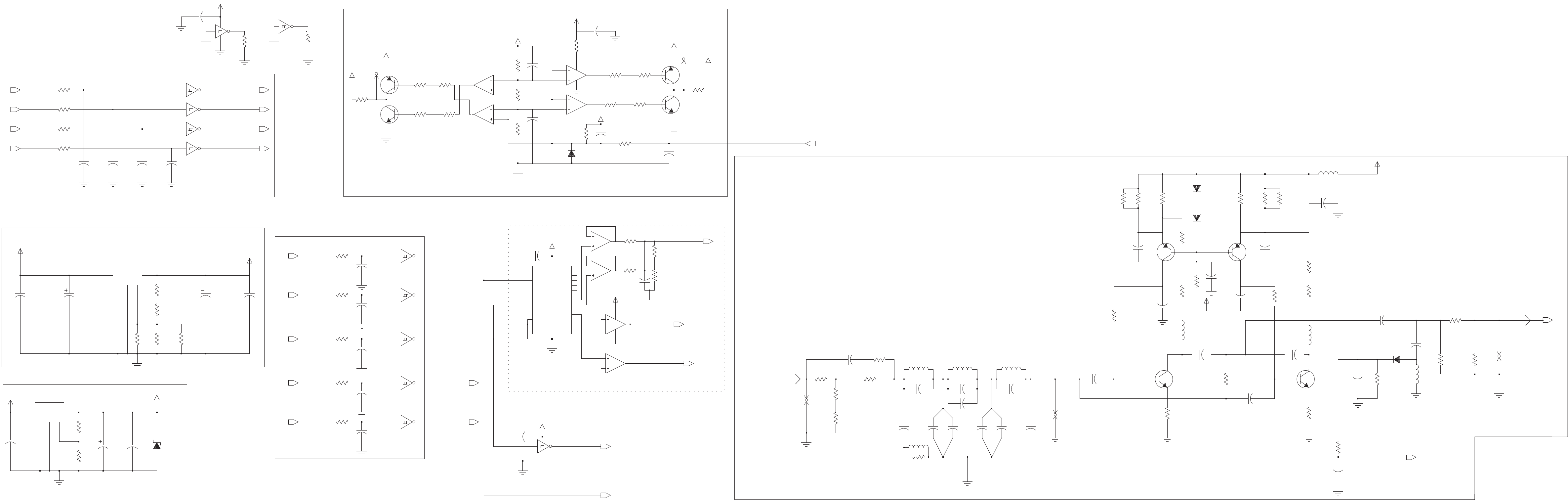
9VREGULATOR
9T/9RGENERATOR
5VREGULATOR TX
EXCITER AMP.(FIRST SECTION)
SPIFILTER
ALC&OCXO TEMP.D/A
VCO_SEL_FILTER
TX
R1219
27
51
R1237
74VHC14
U6077
1 2
51
R1215
SW_A+_RF
24PF
C1231
R1203
470
9V
R1201
1K
9
10
8
39PF
C1233
VDD
U1100
MC33074D
7
GND
13 12
14
VCC
9R
EX_AMP_IN
270NH
L1056
74VHC14
U6077
1K
R1208
R1255
1
C1225
24PF
1K
MC33074D
U1900
2
3
11
Q4-OUT 13
R1-OUT
3
R2-OUT 5
R3-OUT 12
R4-OUT 14
VDD
16
VSS
7
0.1UF
C1205
MC144111
U1104
CLOCK
10
DIN
1
DOUT 15
ENABLE_
6
NC1
8
NC2
9
Q1-OUT 2
Q2-OUT 4
Q3-OUT
9T
C1235
100PF
U1105
74VHC14
3 4
U1106
1
ADJ
3
GND
2
ON_OFF
4VIN 5
VOUT
51
R1254
C1241
33UF
100
R9547
4VIN 5
VOUT
R1214
4.7K
U1107
1
ADJ
3
GND
2
ON_OFF
Q1005
MMBR951
10
8
C1224
100PF
MC33074D
U1900
9
0.1UF
C9537
2.7K
R1230
9T
MC33074D
U1100
6
5
7
MMBD914T
CR1004
Q1010
3906L
9V
R1225
10K
0.1UF
C1216
9R
C1210
0.1UF
R1210
470
470
R1205
R1220
300
R1240
18
0.1UF
C1202
22UH
L1034
R1239
1.2K
C1219
12
R1229
0.1UF
R1224
10K
6
5
7
CR1003
MMBD914T
U1900
MC33074D
C1236
10K
R1231
100
R1226
68PF
R1223
100
C1206
0.1UF
VDD
100
R9539
3K
R1253
0.1UF
C1204
C1240
0.1UF
Q1012
9V 3906L
9V
300
R1218
Q1018
3904L
C1242
0.1UF
U1105
74VHC14
11 10
L1015
270NH
U1105
74VHC14
GND
7
13 12
VCC
14
U1105
74VHC14
5 6
33UF
C1214
9V
11 10
3904L
Q1017
74VHC14
9 8
74VHC14
U6077
L1013
270NH
U6077
15UF
13
12
14
4
11
C1211
R1204
470
MC33074D
U1900
VR1500
5.6V
0.1UF
C1201
470
R1202
R9585
10K
100PF
100NF
C1239
R1248
C1238
10K
R1243
10K
9V
U6077
74VHC14
3 4
100
R1246
10K
R1236
C9541
100PF
24PF
C1227
R1242
470
0
R1206
L1014
270NH
2.7
R1244
C1218
100PF
20PF
C1226
CR1903
R1235
10K
100PF
MMBD914T
470
R1209
C1232
470
R1212
9V
C1245
100PF
R1232
2.7K
0.1UF
C1222 2.7K
R1238
C1228
0.1UF
0.1UF
C1208
24PF
C1234
R1245
2.7
432
R1233
432
MS_2800
CR1001
R1228
74VHC14
U1105
9 8
C1230
100PF
VDD
9R
R9544
100
100
R1227
R1217
300
EX_AMP_OUT
27
R1216
2
R1251
10K
18
74VHC14
U1105
1
C1244
0.1UF
R1241
0.1UF
C1215
0.1UF
C1220
0.1UF
C1207
3906L
Q1008
100
R9543
0
R1200
R9542
100
10K
R1247
5 6
0
R1207
R9546
100 74VHC14
U6077
C1200
VDD
Q1009
3906L
0.1UF
C9539
100PF
L1025
22UH
100
R9541
R9540
100
0.1UF
C1213
4.7UF
C1203
0.1UF
C1223
300
R1221
100
R1222
100
R9545
EX_AMP_LPF
1K
R1213
1000PF
C1217
C1212
0.1UF
10K
R1234
C1237
0.1UF
9V
100PF
C9540
R1252
2.7K
L1024
22UH
22UH
L1214
14
4
11
100PF
C9538
3
1
U1100
MC33074D
13
12
VDD
U1100
MC33074D
2
R1211
470
100NF
C1209
MMBR951
Q1004
10K
R9584
C1221
C1229
24PF
FILT _LOW_RF_SEL
100PF
VCO3_SEL
VCO2_SEL
VCO1_SEL
NOISE_CONTROL
FILT_FRAC_N_1_SEL
FILT_SPI_CLK
FILT_VCO1_SEL
FILT_VCO2_SEL
FILT _VCO3_SEL
FILT _NOISE_CONTROL
SPI_DATA_OUT
SPI_CLK
D2A_OVEN_SEL
LOW_RF_SEL
FRAC_N_1_SEL
FILT_SPI_DATA
TO_HIGH_POWER
PWR_LEVEL
BIAS_OUT
OVEN_TEMP_CNTL1
OVEN_TEMP_CNTL2
PTT_IN
TO_EXCITER
MM-E2072-09333-00
A-31/A-32
Figure A-1.P.LORDModule,
SchematicCircuitDiagram
(Sheet15of15–ExciterandRegulators)
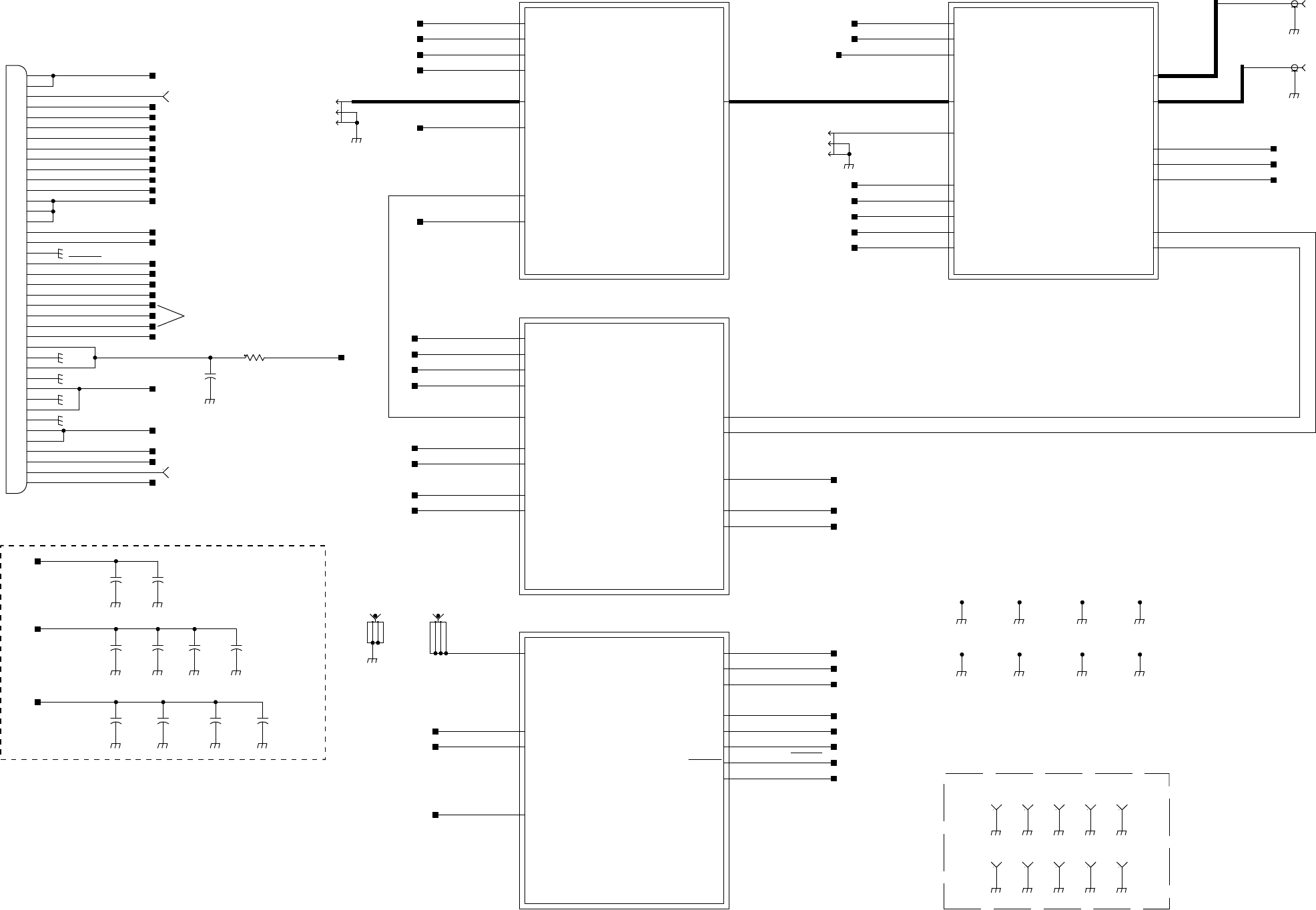
MM-E 2072-09333-00
+10VDC
+5_VCC_FIL
9T
PA_INHIBIT
PA_OUT
RF_INPUT_TX
SW_BATT
TEMP_1
V_ALC
DRIVER_POWER_AMPLIFIER
V_FWD_RADIO
V_REV_TUNE
V_REV_PA_BYPASS
V_FWD_PA_BYPASS
V_REV_RADIO
+5_VCC_FIL
+8VDC
9T
BIT
DC_TO_ANT_CPLR
DIPOLE
PA_OUT
RX_TO_LORD
SPI_CLK_2_PA
SPI_DATA_2_PA
SPI_SEL_2_PA
WHIP
HARMONIC_FILTER
+5_VCC_FIL
+8VDC
9T
ALC_REF_DAC
EXT_AMP_EN
PA_FWD
PA_REV
TEMP_1
V_ALC
V_FWD_PEP
V_FWD_RADIO
V_REV_PEP
V_REV_RADIO
V_TEMP_PA
ALC
EXT DC J5.11
AUDIO AMP
OCXO
CPU
TO REGULATOR U1106
CONTROL HEAD
R122
0.0
LAB
V_FWD_PA_BYPASS
+10VDC
SW_BATT
V_ALC
V_ALC
C127
10U
LAB
SW_BATT
+5_VCC_FIL
V_FWD_RADIO
V_FWD_RADIO
+5_VCC_FIL
V_REV_RADIO
V_REV_RADIO
INT_OSC_SET
BATT_CHECK
V_REV_PA_BYPASS
TP9
C148
100N
10U
C145
9
8
7
6
5
40
4
39
38
37
36
35
34
33
32
31
30
3
29
28
27
26
25
24
23
22
21
20
2
19
18
17
16
15
14
13
12
11
10
1
P3
1040696
SW_BATT
LOW_BATT
DC_PWR_EN
TUNER_CUR_LIM
EXT_AMP_EN
EXT_AMP_EN
TP7
9T
TEMP_1
RF_INPUT_TX
PA_INHIBIT
C153
4.7U
+10VDC
+5_VCC_FIL
BIT
+10VDC
SW_BATT +8VDC
+8VDC
2
1
J2
40330005401
LAB
DIPOLE
1
2
40330005401
J1
LAB
WHIP
DC_TO_ANT_CPLR
+5_VCC_FIL
9T
PA_REV
INT_OSC_SET
BATT_CHECK
+10VDC
+5_VCC_FIL
+8VDC
CH_CHANGE
DC_PWR_EN
DC_PWR_IN
DC_TO_ANT_CPLR
SW_BATT
TUNER_CUR_LIM
LOW_BATT
DC_SUPPLY
INT_OSC_SET
CH_CHANGE
BATT_CHECK
LOW_BATT
+5_VCC_FIL
TUNER_CUR_LIM
SW_BATT
DC_PWR_EN
DC_PWR_IN
+8VDC
DC_TO_ANT_CPLR
+10VDC
1 2 3 4
E1
8191
4321
8191
E2
V_REV_PEP
V_FWD_PEP
TEMP_1
ALC_REF_DAC
9T
SPI_DATA_2_PA
PA_OUT
+5_VCC_FIL
SPI_SEL_2_PA
SPI_CLK_2_PA
V_TEMP_PA
1
2
3
TMP-J01X-A2
P2
RX_TO_LORD
PA_FWD
1
SCR_4_40
MC6
1
MC201
SCR_4_40
1
MC7
SCR_4_40
1
MC5
SCR_4_40
1
SCR_4_40
MC3
1
MC8
SCR_4_40
1
SCR_4_40
MC9
1
SCR_4_40
MC10
1
2
3
TMP-J01X-A2
P4
100N
C149
C146
10U 10U
C147 C150
100N
100N
C151
4.7U
C154
SW_BATT
C152
100N
POWER SUPPLY SHIELD
1
TP12
1
TP14
1
TP13
1
TP16
1
TP15
1
TP21
1
TP20
1
TP19
1
TP18
1
TP17
+5_VCC_FIL
V_TEMP_PA
ALC_REF_DAC
SW_BATT
BIT
PA_REV
PA_FWD
PA_INHIBIT
SPI_CLK_2_PA
SPI_DATA_2_PA
9T
CH_CHANGE
SPI_SEL_2_PA
V_FWD_PEP
V_REV_TUNE
V_REV_PEP
V_FWD_PA_BYPASS
V_REV_PA_BYPASS
V_REV_TUNE
Figure A-2.A. HI POWER Module, Schematic Circuit Diagram (Sheet 1 of 6 – Module Interconnection Diagram)
A-39/A-40
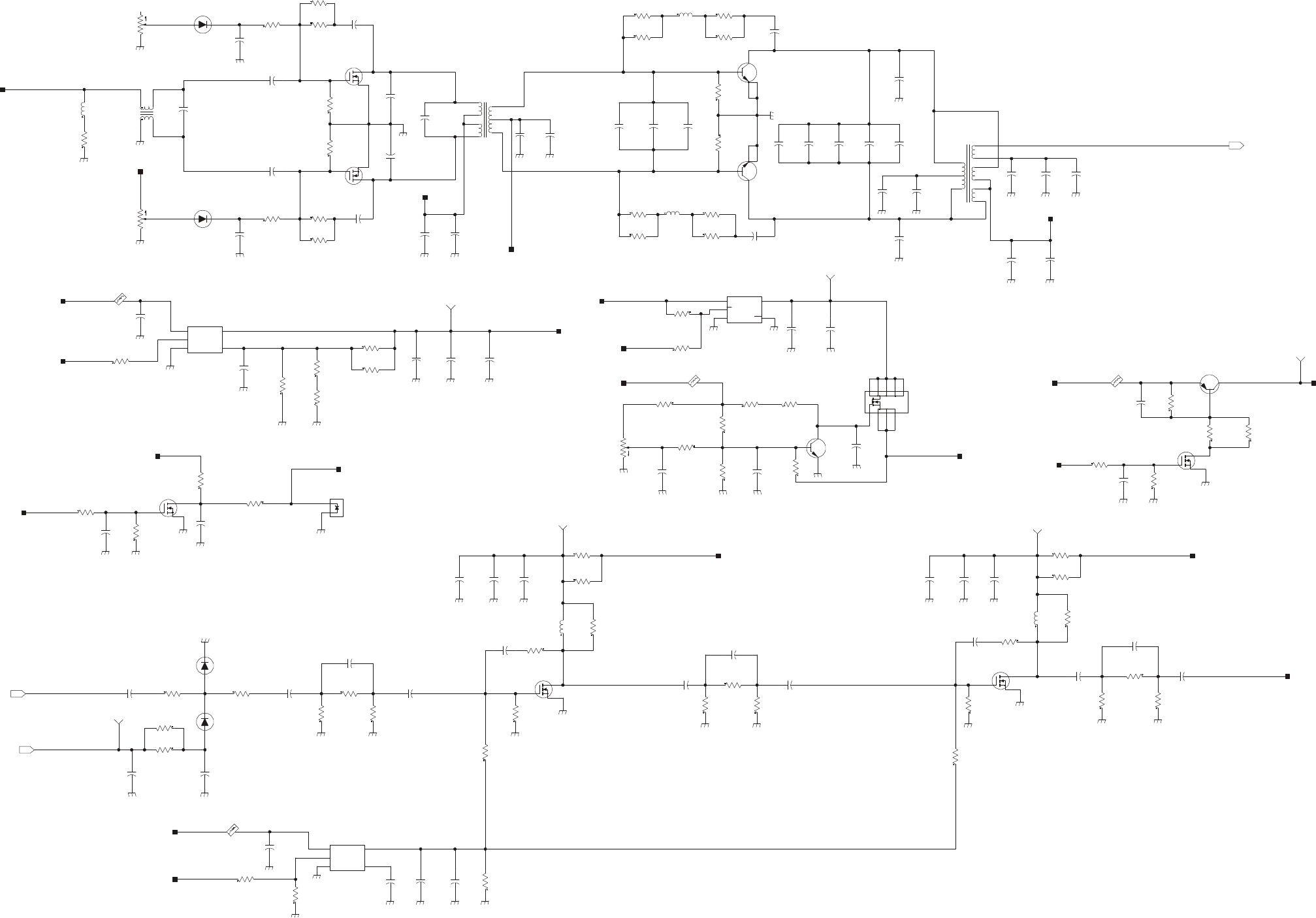
MM-E 2072-09333-00
D
S
G
+
-
+
+
+
D
S
G
CWCW
+
T
D
S
G
ON/OFF
GND BP
VIN VOUT
ADJ
EN
GND
VIN VOUT
+
SD
VIN
GND
VOUT
ERR
D
S
D
D
G
S
D
S
D
T
C
W
+
D
S
G
D
S
G
D
S
G
FOLLOWING CAPACITORS SHOULD NOT BE ASSEMBLED:
C40, C24, C865, C863, C864, C29, C28
301
R50
R55
301
301
R80
9
8
7
6
3
4
2
5
1
20721302600
T1
C24
470P
R164
1.50K
TP5
BLM31PG601SN1L
E27
10N
C137
C136
10N
51.1K
R154
3
1
2
Q12
BST82
2
3
1
Q10
MMBT4403LT3
R153
51.1K
R69
1K
1.50K
R163
1K
R46
C56
100N
51.1K
R13
R5
24.3
TP8
LAB
R45
301
LAB
301
R38
LAB
OPT
C31
LAB
OPT
R42
C19
10N
R131
1
3
1
2
Q7
RD00HHS1
56U
L2
C44
100N
100N
C43 C34
100N
100N
C26
2.2U
C2
1
R132
100N
C60
R62
301
LAB
C64
OPT
LAB
R56
OPT
R130
1
R129
1
L19
56U
3
1
2
RD00HHS1
Q5
301
R63
R57
18.2
1.50K
R830
47U
C4
TP6
LAB
10K
R3
13
2
R22
10K
RT1
NT732BTTD102J3200K
BLM31PG601SN1L
E26
22.1
R829
100N
C18
C17
100N
100
R833
1
2
3
Q2
MMBT2222ALT1
5
6
7
3
2
1
4
8
9
SI7856DP
Q8
10N
C848
10N
C850
2.74K
R822
R819
2.74K
47.5K
R823
1
2
5
3
4
LP3961EMP-3.3
U11
R2
100
E7
C14
100N
1N
C37
100N
C36
10N
C38
15U
C15
470P
C28
C40
470P
C871
100N
100N
C41
C29
470P
C864
470P470P
C863
330P
C865
2
1 3
4
2SC2879A
Q11
R26
33.2
33.2
R27R21
33.2
33.2
R24
33.2
R43
R44
33.2 33.2
R40
R41
33.2
C21
100N
470P
C853
2
1 3
4
Q6
2SC2879A
68N
L11
C861
330P330P
C862
R28
4.7
4.7
R31
1N
C30
C869
100N
68N
L17
C48
100N
10N
C51
C47
10N
47P
C144
LAB
C25
180P
LAB
180P
C33
LAB
4
3
2
1 5
MIC5205BM5
U6
R25
51.1
51.1
R23
R883
0.0
TP1
R127
71.5K
R121
909K 24.3K
R125
R128
24.3K
R11
100
10U
C1
1K
R59
R1
100
BLM31PG601SN1L
E3
R4
3.32K
3
2 4
1 5
U1
LP2985AIM5-3.3
C5
10N
C81
OPT
LAB
OPT
R169
LAB
2.2U
C16
100N
C27
C98
100N 10N
C96
3
1
2
RD16HHF1-101
Q4
470P
C94
RT2
NT732BLTD104J3800J
L9
330N
LAB
1
4
3
6
2089-13023-00-0
T3
E22
4.7U
C62
1
3
2
R67
10K
1
3
2
10K
R73
BLM31PG601SN1L
E29
3
1
2
Q3
RD16HHF1-101
C860
56P
100N
C52
R29
412
412
R30
R34
10K
1 3
CR10
MMBD914LT1
C49
100N
100N
C852
1
6
7
2
4
5
3
T2
20721300600
C854
47U
C873
15U
10K
R35
R33
412
412
R32
100N
C59
1 3
MMBD914LT1
CR11
C20
10N
C45
100N
100N
C76
13
CR9
HSMP3810
1 3
CR8
HSMP3810
C80
100N
R78
24.924.9
R77
R79
301
R97
150
C89
100N
C79
100N
150
R98
100N
C91
R76
18.2
10U
C55
10N
C6
4.7U
C3
10K
R75
51.1K
R167
2
1
VR3
LM4040CEM3X-5.0
4.75K
R72
3
1
2
BST82
Q19
C894
10N
LAB
R71
4.75K
10K
R884
C895
10N
SW_BATT
9T
VDD_PREAMP
PRE_DRIVER
VDD_PREAMP
BIAS_EN
+5_VCC_FIL
VDD_PREAMP
+10VDC
PWR_AMP_BIAS
PA_OUT
SW_BATT
PA_INHIBIT
BIAS_EN
V_ALC
PRE_DRIVER
PWR_AMP_BIAS
DRIVER_BIAS
+10VDC
SW_BATT
RF_INPUT_TX
DRIVER_BIAS
+10VDC
BIAS_EN
9T
TEMP_1
Figure A-2.B. HI POWER Module, Schematic Circuit Diagram (Sheet 2 of 6 – Driver & Power Amplifier)
A-41/A-42
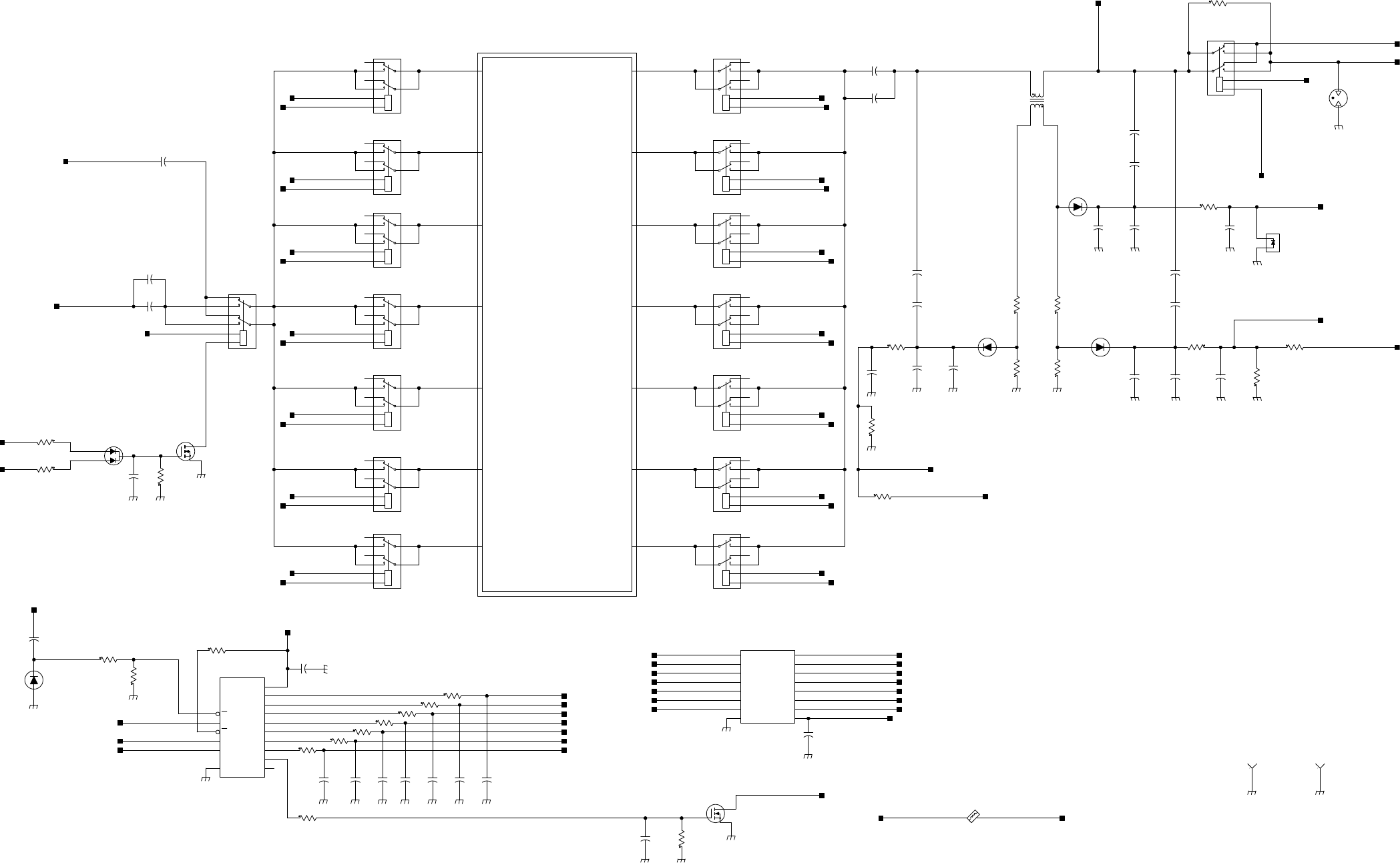
MM-E 2072-09333-00
DCOM
GND
I1
I2
I3
I4
I5
I6
I7
O1
O2
O3
O4
O5
O6
O7
D
S
G
-
+
-
+
-
+
-
+
-
+
-
+
-
+
-
+
OE
MR
VCC
STCP
SHCP
Q7S
Q7
Q6
Q5
Q4
Q3
Q2
Q1
Q0
GND
DS
-
+
-
+
D
S
G
-
+
-
+
+
-
+
-
+
-
+
-
+
RANGE1_IN
RANGE2_IN
RANGE3_IN
RANGE4_IN
RANGE5_IN
RANGE6_IN
RANGE7_IN
RANGE5_OUT
RANGE1_OUT
RANGE2_OUT
RANGE3_OUT
RANGE4_OUT
RANGE6_OUT
RANGE7_OUT
FILTERS
+
-
1.6-2.429 MHz
2.43-3.69 MHz
3.7-5.59 MHz
5.6-8.49 MHz
8.5-12.99 MHz
13.0-19.79 MHz
19.8-30.0 MHz
R36
0.0
WHIP
DC_TO_ANT_CPLR
DIPOLE
1
2
LM4040CEM3X-5.0
VR803
2
1
10
7
9
4
8
3
EB2-5-NU
K301
3
8
4
9
7
10
1
2
K201
EB2-5-NU
3
8
4
9
7
10
1
2
K302
EB2-5-NU
3
8
4
9
7
10
1
2
EB2-5-NU
K202
C32
47U
R87
24.924.9
R86
2
1
E19
CG2470LSTR
3
8
4
9
7
10
1
2
K2
EB2-5-NU
LAB
SEL_ANT
13
2
CR805
MMBD6100LT1
+5_VCC_FIL
1
E23
PAD_DRILLXX
+5_VCC_RLY
+5_VCC_RLY
+5_VCC_RLY
+5_VCC_RLY
+5_VCC_RLY
+5_VCC_RLY
+5_VCC_RLY
+5_VCC_RLY
+5_VCC_RLY
+5_VCC_RLY
+5_VCC_RLY
+5_VCC_RLY
+5_VCC_RLY
+5_VCC_RLY
+5_VCC_RLY
+5_VCC_RLY
+5_VCC_RLY
+5_VCC_RLY
E6
BLM31PG601SN1L
FLTR_4_DRIVEFLTR_4_SET
FLTR_1_SET FLTR_1_DRIVE
FLTR_2_SET
C875
100N
C707
100N
PA_OUT
FLTR_3_DRIVE
FLTR_5_DRIVE
FLTR_7_DRIVEFLTR_7_SET
FLTR_5_SET
FLTR_3_SET
FLTR_3_SET
FLTR_2_SET
FLTR_1_SET
FLTR_7_SET
FLTR_6_SET
FLTR_5_SET
10P
C77
R865
100K
R850
24.3
+5_VCC_FIL
180P
C82
C78
180P
C84
47P
1N
C88
47P
C83
C902
100P
2
1
10
7
9
4
8
3
EB2-5-NU
K701
1 3
CR806
MMBD914LT1
1K
R848
100N
C23
10P
C903
10P
C74
C851
10N
R81
24.9 24.9
R82
1 3
CR810
HSMS2800
BITE
TX
3
12
Q805
BST82
V_REV_TUNE
V_REV_PA_BYPASS
1N
C886
C872
1N
24.3
R849
FLTR_7_DRIVE
BIT
9T
1.21K
R836
TX/RX_DRIVE
1
2
3
4
T4
20721300700
C72
10P
10P
C75
C66
10P
C65
10P
3
8
4
9
7
10
1
2
K1
EB2-5-NU
1.21K
R83
0.0
R91
R92
0.0
C906
1N
R923
10K
FLTR_6_DRIVE
FLTR_5_DRIVE
FLTR_4_DRIVE
FLTR_3_DRIVE
FLTR_2_DRIVE
FLTR_1_DRIVE
C87
1N
2
1
10
7
9
4
8
3
EB2-5-NU
K101
13
CR6
HSMS2800
C708
10N
R844
24.3K
R842
18.2K
SPI_CLK_2_PA
SPI_DATA_2_PA
13
10
16
12
11
9
7
6
5
4
3
2
1
15
8
14
U4
74HC595D
C867
1N1N
C855C866
1N1N
C870C868
1N
1N
C858
24.3
R846
24.3
R839
24.3
R841
R843
24.3
R845
24.3
3
8
4
9
7
10
1
2
K601
EB2-5-NU
2
1
10
7
9
4
8
3
EB2-5-NU
K501
3
8
4
9
7
10
1
2
K401
EB2-5-NU
R840
24.3
SPI_SEL_2_PA
3
8
4
9
7
10
1
2
EB2-5-NU
K602
3
8
4
9
7
10
1
2
K502
EB2-5-NU
3
8
4
9
7
10
1
2
EB2-5-NU
K402
3
8
4
9
7
10
1
2
K102
EB2-5-NU
3
8
4
9
7
10
1
2
K702
EB2-5-NU
3
12
Q801
BST82
R835
51.1K
10N
C22
R85
1.21K
FLTR_1_DRIVE
FLTR_2_DRIVE
FLTR_3_DRIVE
FLTR_4_DRIVE
FLTR_5_DRIVE
FLTR_6_DRIVE
FLTR_7_DRIVE
31
HSMS2800
CR7
R837
1.21K
V_FWD_PA_BYPASS
SEL_ANT_DRIVER
51.1K
R89
V_FWD_RADIO
V_REV_RADIO
51.1K
R90
SEL_ANT_DRIVER
98
1
2
3
4
5
6
7
16
15
14
13
12
11
10
U3
ULQ2003LTR
C856
100N
C905
100N
RX_TO_LORD
FLTR_2_DRIVE
FLTR_6_DRIVEFLTR_6_SET
1
PAD_DRILLXX
E24
RANGE1_OUT
RANGE2_OUT
RANGE3_OUT
RANGE4_OUT
RANGE5_OUT
RANGE6_OUT
RANGE7_OUTRANGE7_IN
RANGE6_IN
RANGE5_IN
RANGE4_IN
RANGE3_IN
RANGE2_IN
RANGE1_IN
FLTR_4_SET
+8VDC
Figure A-2.C. HI POWER Module, Schematic Circuit Diagram (Sheet 3 of 6 – Harmonic Filter, Part I)
A-43/A-44
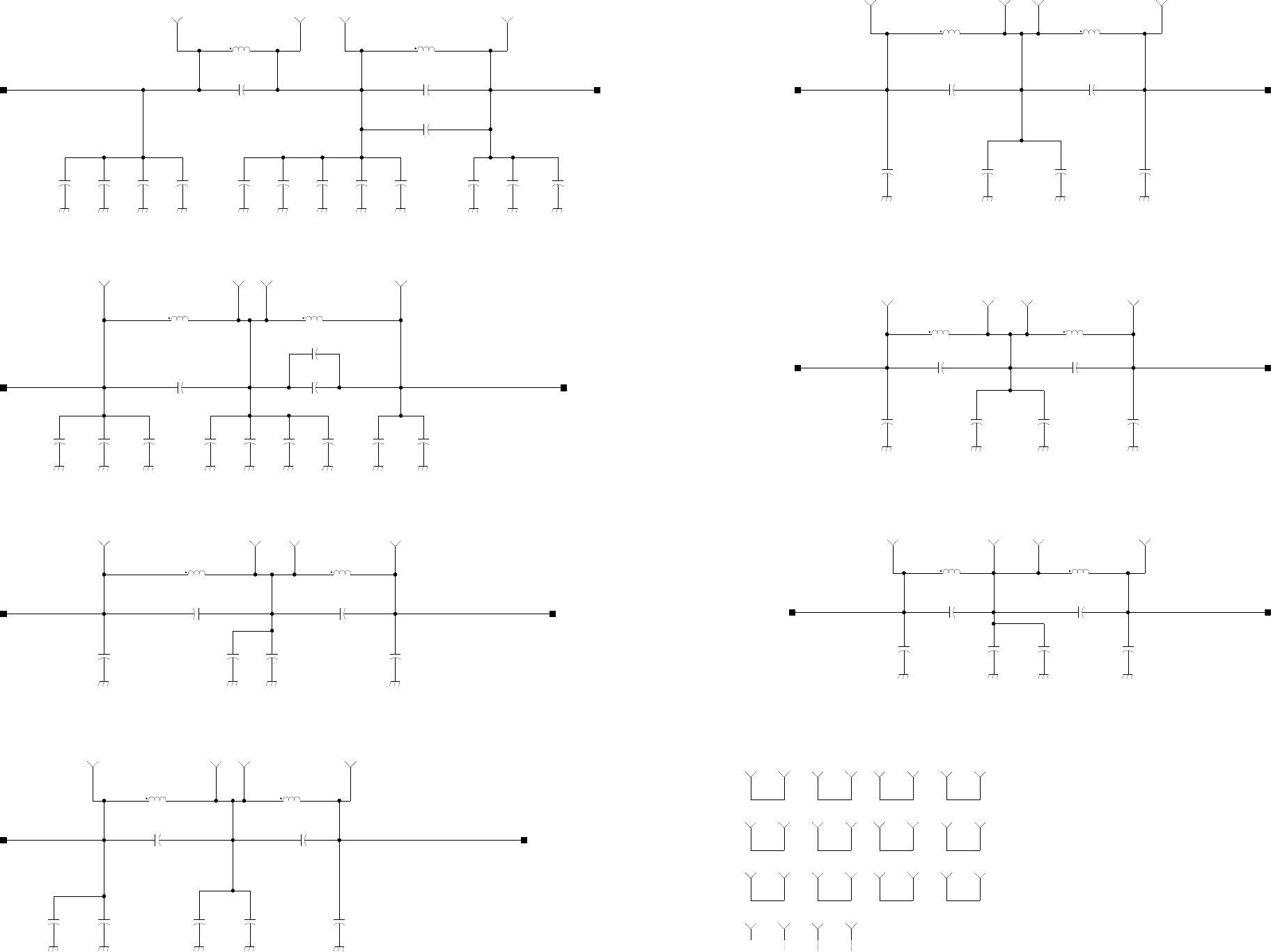
MM-E 2072-09333-00
NOT ASSEMBLED: C104, C210,C705
1
E603
1
E201
1
E304
1
E103
1
E602
1
E601
1
E604
1
E502
1
E504
1
E503
1
E501
1
E703
1
E701
1
E402
1
E404
1
E403
1
E401
1
E303
1
E301
1
E102
1
E104
1
E101
1
E202
1
E204
1
E203
1
E302
1
E702
1
E704
DRILL 0.85 MM
FILTER#1 1.6-2.43 MHZ
3.5 UH 2.8 UH
T=18 T=16
1
TP4
1
TP26
C101
150P
C104
68P
LAB
L101
3.39U
20721302313
L102
5.20U
20721302314
470P
C112
470P
C107
470P
C114
470P
C102
470P
C108
470P
C113
470P
C110
470P
C105
470P
C106
470P
C111 C109
470P
C115
180P
C103
240P
RANGE1_OUTRANGE1_IN
1
TP24
1
TP25
FILTER#2 2.43-3.7 MHZ
T=14 T=13
330P
C204C205
330P330P
C211 C210
47P
LAB
C206
270P
470P
C208
L201
2.20U
20721302311
L202
2.60U
20721302312
470P
C202
470P
C207
470P
C212
C201
150P
C209
68P
C203
180P
1
TP27
1
TP28
1
TP29
1
TP30
RANGE2_IN RANGE2_OUT
FILTER#3 3.7-5.6 MHZ
T=12 T=10
C303
100P
330P
C305
330P
C301
C306
470P470P
C302
L301
1.35U
20721302309
L302
1.90U
20721302310
470P
C304
1
TP31
1
TP32
1
TP33
1
TP34
RANGE3_IN RANGE3_OUT
FILTER#4 5.6-8.5 MHZ
T=9 T=8
1
TP37
1
TP36
200P
C406 C405
200P
C403
82P
100P
C407
L401
0.88U
20721302307
L402
1.12U
20721302308
C404
220P
C402
390P
C401
220P
1
TP35
1
TP38
RANGE4_IN RANGE4_OUT
FILTER#5 8.5-13.0 MHZ
T=7 T=6
1
TP41
1
TP40
C504
100P
1
TP39
150P
C503
180P
C501
C506
180P180P
C505
C502
56P
L501
0.55U
20721302305
L502
0.71U
20721302306
1
TP42
RANGE5_IN RANGE5_OUT
FILTER#6 13.0-19.8 MHZ
T=6 T=5
1
TP43
1
TP44
C605
56P
C601
82P
C603
30P
C604
150P 22P
C602
270P
C606
L601
0.55U
20721302303
L602
0.55U
20721302305
1
TP45
1
TP46
RANGE6_IN RANGE6_OUT
FILTER#7 19.8-30.0 MHZ
T=4 T=4
20721302301
0.28U
L702 L701
0.28U
20721302301
C705
100P
LAB
100P
C702 C706
82P82P
C704
C703
18P
C701
56P
1
TP47
1
TP48
1
TP49
1
TP50
RANGE7_IN RANGE7_OUT
Figure A-2.D. HI POWER Module, Schematic Circuit Diagram (Sheet 4 of 6 – Harmonic Filter, Part II)
A-45/A-46
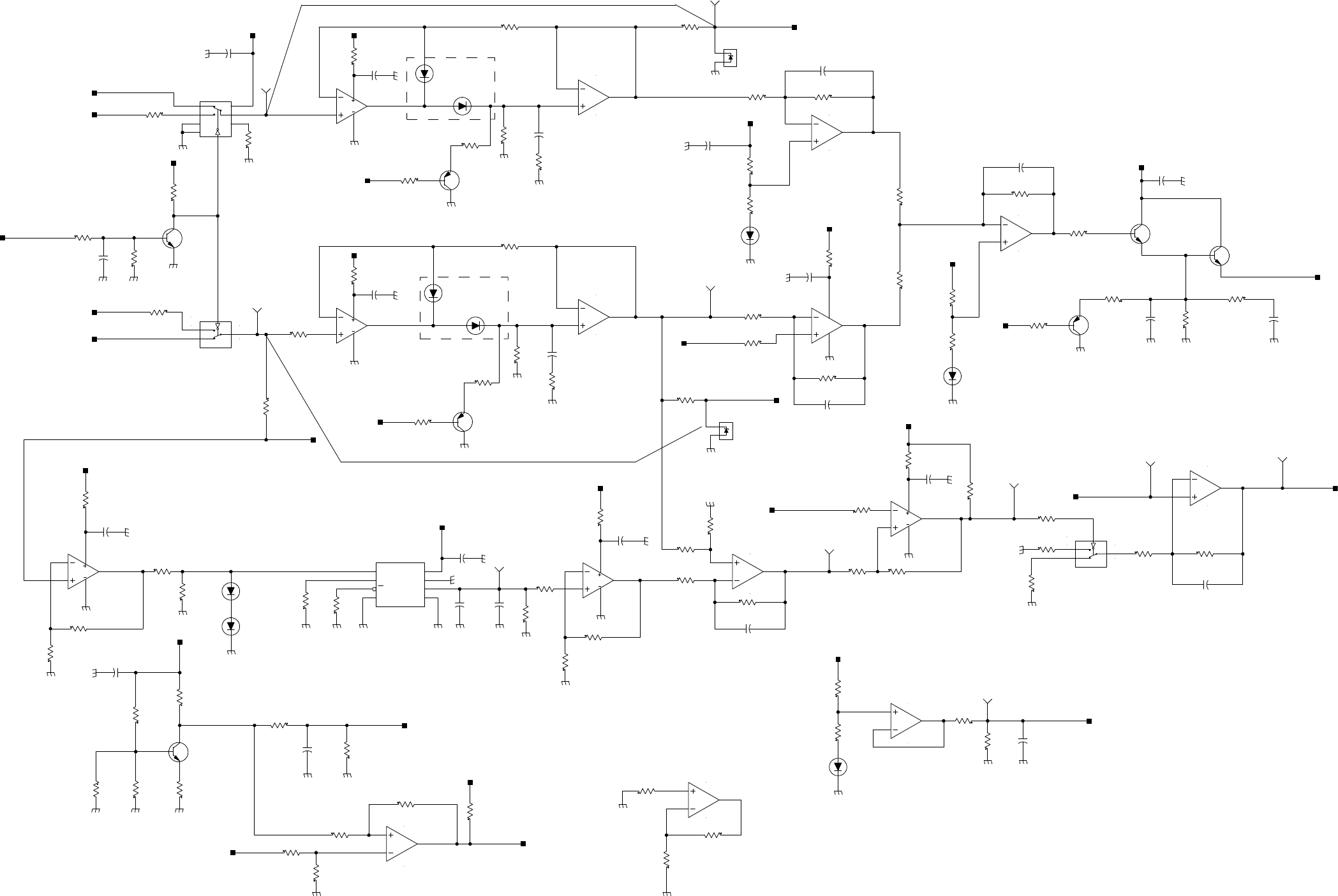
MM-E 2072-09333-00
V
V
V
V
GND
INH
VCC
VEE
V
V
+
V+
V-
IN1
IN2
EN
GND VSS
VCC
OUT-RTN
VOUT
V
V
+
-
+
-
V
V
2
3
1
4
8
U15
LMC6482AIMX
R919
10K
4
8
7
6
5
LMC6482AIMX
U15
100N
C904
100
R921
1
2
LM4040CEM3X-5.0
VR801
2
1
VR802
LM4040CEM3X-5.0
V_FWD_PEP
V_FWD_PEP
V_REV_PEP
+8VDC
V_REV_PEP
1K
R918
C119
470P
LAB
150K
R914
R902
82.5K
C117
560P
LAB
0.0
R928
R892
475
LAB
R99
10K
LAB
2
3
1
Q25
MMBT4403LT3
LAB
51.1
R96
LAB
182
R95
LAB
R105
0.0
51.1K
R869
LAB
13
CR808
MMBD914LT1
LAB
R873
5.62K
LAB
8
4
7
5
6
LMC6482AIMX
U8
LAB
R877
53.6K
LAB
C890
22N
LAB
R878
10K
LAB
10K
R897
LAB
3
2
1
8
4
U8
LMC6482AIMX
LAB
R896
2.21K
LAB
10K
R899 LAB
C891
100N
LAB
R879
100
LAB
R898
1K
LAB
1N
C69
LAB
100N
C61
LAB
2
3
8
1 4
7
6
5
U7
LTC1966IMS8
LAB
1K
R880
LAB
10K
R108
LAB
3 1
MMBD914LT1
CR5
LAB
13
CR4
MMBD914LT1
LAB
R74
3.32K
LAB
10K
R920
LAB
R147
0.0
LAB
4.7U
C120
LAB
C92
10U
LAB
R925
1K
LAB
1K
R866
LAB
9T
PA_FWD
EXT_AMP_EN
9T
+8VDC
C68
100N
LAB R126
10K
LAB
10K
R52
LAB
1
3
2
MMBT4403LT3
Q18
LAB
24.3
R54
LAB
R94
10K
LAB
2
3
1
Q24
MMBT4403LT3
LAB
24.3
R93
LAB
R882
OPT
LAB
R109
OPT
LAB
OPT
R84
LAB
OPT
R926
LAB
E11
R917
100
C156
470P
C67
100N
54
3
86
9
16
7
U12
MC14053BD
ALC_REF_DAC
13
CR2
MMBD914LT1
LAB
+5_VCC_FIL
+8VDC
+8VDC
+8VDC
100K
R910
14
7
3
2
4
U13
LM2900DR
R53
100
R106
150
R874
1M
C85
220U
LAB
+8VDC
R888
82.5K
475K
R51
R88
475K
6
5
7
48
U10
LMC6482AIMX
84
1
3
2
LMC6482AIMX
U14
4
8
7
6
5
LMC6482AIMX
U14
SPARE
27.4K
R887
R904
3.32K
R909
475K
11
12
147
10
U13
LM2900DR
8
13
147
9
U13
LM2900DR
6
1
147
5
U13
LM2900DR
215
1
86
10
7
U12
MC14053BD
E14
1K
R912
R68
0.0
12
1413
8
6
11
16
7
U12
MC14053BD
R60
0.0
1
3
2
Q807
MMBT2222ALT1
V_ALC
2
3
1
MMBT2222ALT1
Q23
1
3
2
Q22
MMBT2222ALT1
+8VDC
2.2U
C90
C58
2.2U
R64
1K
10N
C901
R870
51.1K
+8VDC
5.62K
R893
9.76K
R871
4 1
CR811
MA4CS101E
ALC_REF
E15
3 2
CR811
MA4CS101E
V_FWD_RADIO
V_REV_RADIO
5
6
7
8
4
U9
LM2903D
100K
R908
10K
R875
R907
21.5K
6
5
7
48
U5
LMC6482AIMX
3
2
1
8
4
U5
LMC6482AIMX
R916
10K
+8VDC
R61
36.5K
R906
51.1K
R913
100K
+8VDC
R70
10K
R903
56.2K
PA_REV
100N
C887
R911
100K
R58
3.32K
R901
47.5K
R922
182
13
CR1
MMBD914LT1
R915
2.74K
100N
C86
C896
100N
9T
R867
1K
C57
100N
100N
C900
1K
R924
100
R905
+8VDC
R876
100
C889
100N
E13
23
MA4CS101E
CR809
14
MA4CS101E
CR809
E18
E12
E10
E21 E20
10N
C898
REF_PEP_RMS
E16
150
R107
ALC_REF
REF_PEP_RMS
+8VDC
T
R894
21.5K R172
15K
150K
R173
TEMP_1
10K
R895
R862
10K
3
2
1
8
4
U9
LM2903D
10K
R171
RT3
NT732BLTD104J3800J
1
3
2
Q806
MMBT2222ALT1
R863
27.4K R886
8.25K
8.25K
R885
C897
100N
+8VDC
R868
2.74K
R881
475
100N
C884
V_TEMP_PA
+8VDC
+8VDC
Figure A-2.E. HI POWER Module, Schematic Circuit Diagram (Sheet 5 of 6 – ALC Circuits)
A-47/A-48
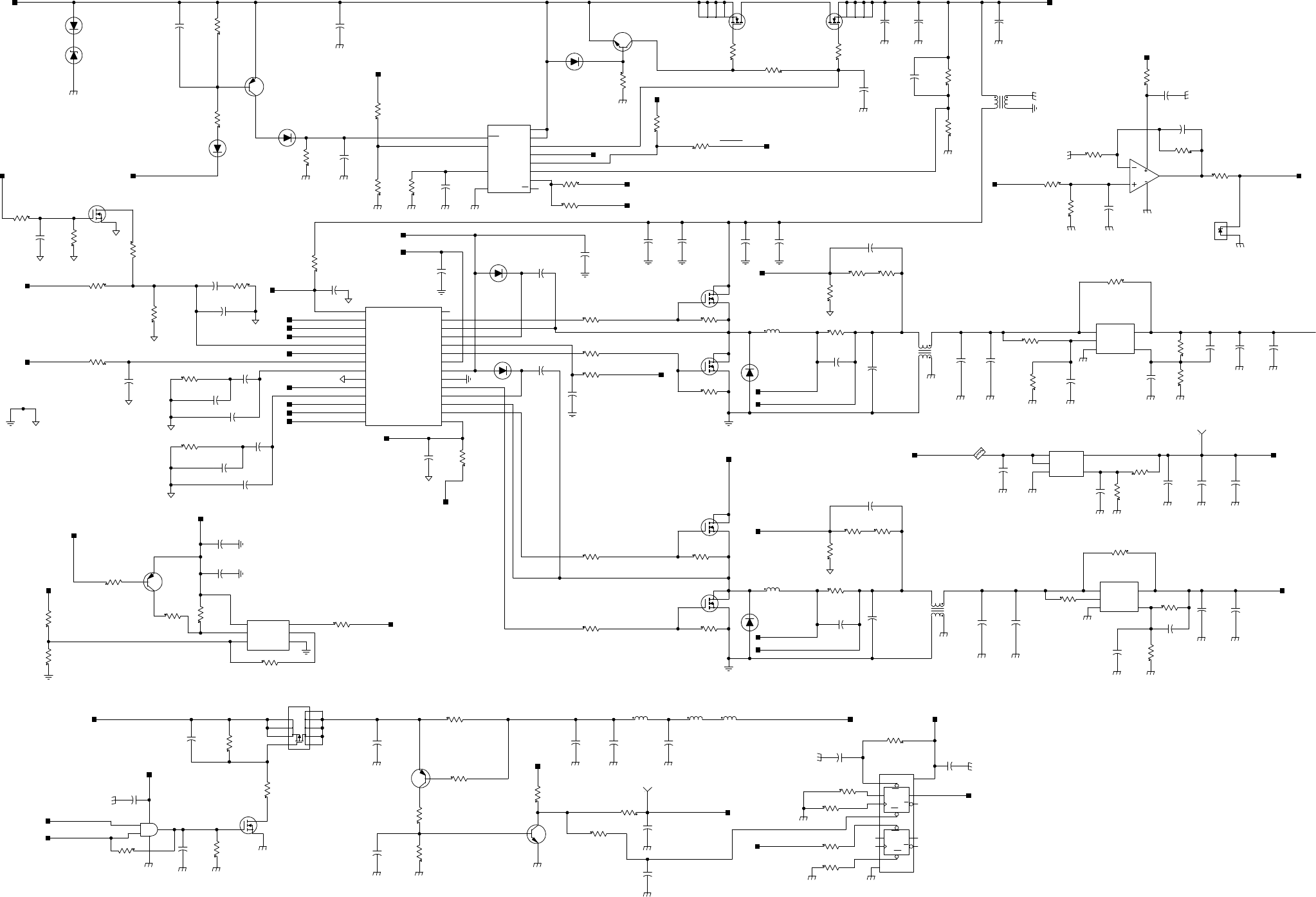
MM-E 2072-09333-00
+
V
V
+
DS
S
S
G
D
D
D
D
CP1
CP2
D1
D2
GND
Q1
Q2
VCC
CD1
CD2
Q1
Q2
SD1
SD2
VCC
GND
+
ADJ
EN
GND
VIN
VOUT
GND
VIN
ADJ
VOUT
EN
+
-
D
S
G
+
D
S
G
SET
MOD
OUT1
OUT2
GND
V+
TG1
SW1
SENSE2-
RUN/SS1
SENSE1+
SENSE1-
V0SENSE1
FCB
SGND
3.3VOUT
ITH2
V0SENSE2
SENSE2+
ITH1
PLLIN
PLLFLTR
RUN/SS2
TG2
SW2
BOOST2
BG2
PGND
INTVCC
EXTVCC
BG1
VIN
BOOST1
PGOOD
S
D
S
S
S
S
G
S
D
S
S
S
S
G
+
+
+
+
+
+
+
GND
VIN
ADJ
VOUT
EN
SHDN
IN+
EN
FB
VCC
SNS
GAITE
AOUT
OUT
GND
TMR
FLT
R178
0.0
100K
R115
LAB
PWM_EN
C168
1N
1N
C166
R113
100K
LAB
PWM_EN
SW_BATT_PS
100K
R116
R149
10 10
R176
+5_VCC_FIL
10U
C174
R179
51.1K
+10VDC
C124
10U
7
12
8
9
2
6
5
4
11
3
10
1
U23
LT4356IDE-1
C42
33P
LAB
R119
15K
C54
33P
LAB
R123
15K
LOW_BATT
R37
100
LAB
R160
10K
LAB
C123
10U
10U
C93
LAB
OPT
C159
C7
OPT
LAB
3
2
5
4
1
U21
MIC29152BU
C139
4.7U
1
4 3
2
T7
22U
+5.5VDC
-SENSE_5V
1
4 3
2
T5
22U
SW_BATT
+10.5VDC
C140
4.7U
LAB
C172
100N
4.7U
C100 C158
4.7U
3.3V_OUT
100N
C133
LAB
8
7
2 1
Q1
SI9945DY-TR
6
5
4 3
Q1
SI9945DY-TR
15U
C128C134
15U
C121
100U
2
3 4
1
22U
T6
22U
C73
SW_BATT_PS
C129
22U
C131
47U
C846
47U
0.02
R156
R157
0.02
SW_BATT
10UH
L3
L1
10UH
INTVCC_5V
DRAIN
3
2
5
6
7
1
4
IRFS3004-7PPBF
Q14
4
1
7
6
5
2
3
Q26
IRFS3004-7PPBF
DC_PWR_IN
R114
82.5K
CR14
MURS160T3
100N
C157
100N
C165
R170
100K
LAB
100K
R161
R162
750K
CR17
MBR140SFT1
1
3
2
MMBT4403LT3
Q20
C173
100P
C164
100N
R177
909K
27
26
13
1
2
3
4
7
9
10
11
12
14
8
6
5
15
16
17
18
19
20
21
22
23
24
25
28
U20
LTC1628IG-SYNC
R168
2.2M
LAB
R152
475K
LAB
3.3V_OUT
SYNC
3.3V_OUT
3
4
6
5
2
1
U17
LTC6908IS6-1
LAB
INT_OSC_SET
LAB
0.0
R10
R19
0.0
LAB
LAB
0.0
R139
INTVCC_5V
R15
0.0
2.2U
C171
C167
100N
INTVCC_5V
C135
4.7U
21.5K
R142
LAB
15K
R112
4.75K
R111
INT_OSC_SET
51.1K
R141
LAB
R134
51.1K
2
3
1
Q9
MMBT4403LT3
LAB
0.0
R17
LAB
R146
0.0
LAB
R16
0.0
LAB
R140
51.1K
LAB
10N
C125
LAB
3
1
2
Q21
BST82
LAB
100U
C160
+10VDC
2
1
3
BST82
Q17
R138
24.3K
100N
C162
C888
100N
SW_BATT
R137
100K
R174
10K
2
1
VR4
LM4040CEM3X-5.0
1K
R891
C170
100N
LAB
SW_BATT
SW_BATT
8
7
2 1
Q13
SI9945DY-TR
6
5
4 3
Q13
SI9945DY-TR
SW_BATT_PS
SW_BATT_PS
TUNER_CUR_LIM
100N
C885
10K
R110
E9
R39
0.2
+5_VCC_FIL
R860
10K
21.5K
R855
R857
51.1K
51.1K
R145
4.7U
C880
100N
C12
C130
100N
R120
5.11K
+5_VCC_FIL
51.1K
R135
2
3
1
MMBT2222ALT1
Q16
R143
51.1K
DC_PWR_EN
CR13
MBRS360T3
VR2
LNBTVS6-221S
10K
R65
C169
100N
LATCH
CH_CHANGE
+8VDC
DC_TO_ANT_CPLR
180P
C71
180P
C70
C39
33P
LAB
C10
1N
C35
33P
LAB
C63
33P
VOSENSE_10V
VOSENSE_5V
+SENSE_5V
SYNC
100N
C53
C143
100N
-SENSE_10V
+SENSE_10V
+SENSE_10V
VOSENSE_10V
VOSENSE_5V
-SENSE_5V
+SENSE_5V
21.5K
R150
R144
51.1K
R136
51.1K
R151
8.25K
R117
110K
C9
1N
R155
215K
C163
100N
CR20
MBR140SFT1
CR19
MBR140SFT1
2
1
TP11
SHORTING_PAD
R6
1
R158
20.0K
R7
1
R159
20.0K
CR16
MBR140SFT1
R8
1
R9
1
C161
100N
CR18
MBR140SFT1
C142
10N
C11
1N
CR15
MBR140SFT1
R124
51.1K
R133
51.1K
R148
10
C8
1N
C141
10N
R118
15K
EXT5V
R12
0.0 LAB
1
4
5
2
3
MIC29152BU
U2
10K
R818
470P
C118
C13
10N
R18
10K
R20
31.6K
R14
0.0 LAB
470P
C126
R175
10K 150K
R165
21.5K
R166
C116
100N
BLM31PG601SN1L
E28
51
2
3
4
MIC5205BM5
U16
E31
470P
C97
R104
27.4K
R102
150K
10N
C99
4.7U
C95
C882
100N100N
C877C46
100N
1
2
5
3
4
U19
NC7SZ08P5X
R103
10K
R101
10K
3
11
2
12
7
9
1
13
5
14
6
8
4
10
U22
74VHC74MTCX
10K
R100
R47
10K
9
8
3
2
1
4 5
6
7
SI7483DP
Q15
33UH
L18L14
33UH
1K
R861
2
3
1
MMBT2222ALT1
Q803
10K
R48
C50
10N
R852
86.6
2
3
1
Q802
MMBT4403LT3
51.1K
R49
15U
C878
L20
33UH
C132
100N
10K
R66
LATCH
+5_VCC_FIL
+5_VCC_FIL
SW_BATT
+5_VCC_FIL
R890
OPT
LAB
3
2
1
8
4
LMC6482AIMX
U10
C155
1N
R872
100
+8VDC
BATT_CHECK
C122
100N
-SENSE_10V
C138
15U
PWM_EN
Figure A-2.F. HI POWER Module, Schematic Circuit Diagram (Sheet 6 of 6 – Power Supply)
A-49/A-50
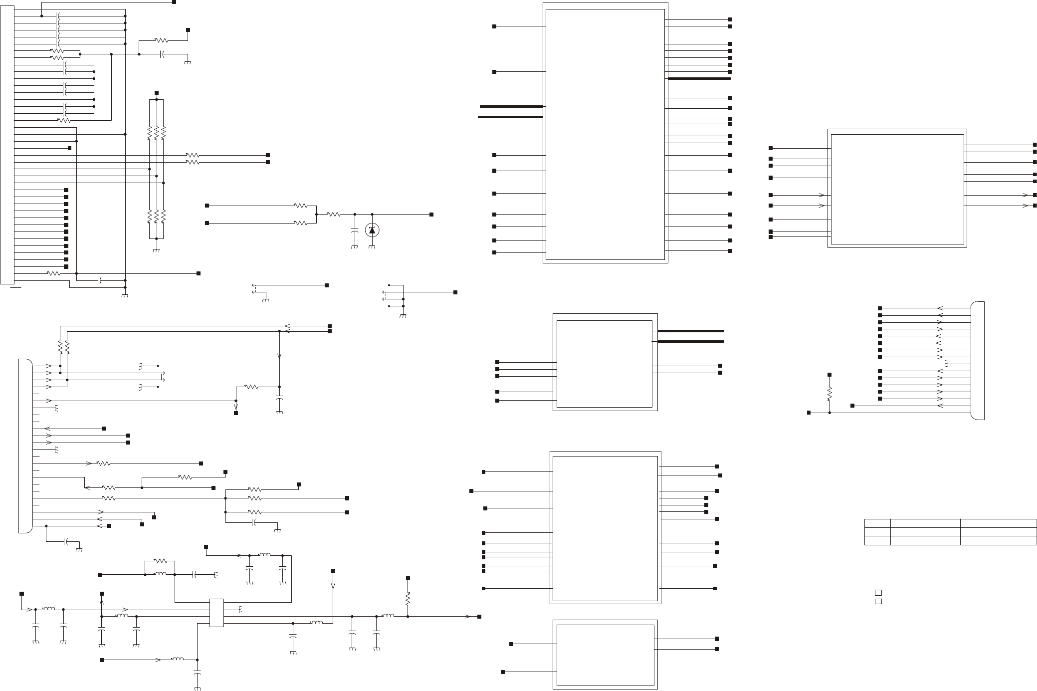
MM-E 2072-09333-00
SH_DN_232_N
ON_OFF_SW POW_OFF_CPU
3V3
A0_CPU
CPU_D[7:0]
KB_BL_EN
KEY_X[4:0]
KEY_Y[4:0] LCD_BL_EN
LCD_BL_LEVEL
LCD_HEAT_EN
LCD_HEAT_LEVEL
MISO_CPU MOSI_CPU
PTT_MIC_N PTT_MIC_P_CPU
RD_N_CPU
RST_N_LCD
RX_UART0_TTL
RX_UART1_TTL
SCL_CPU
SDF_SW_DET
TX_UART0_TTL
TX_UART1_TTL
V0_LCD
VLED_HEAT_EN
WR_N_CPU
XCS_N_LCD
XCS_N_SDF
XIL_MONITOR
TAD_CODAN_MODE
MZ_CPU
UART0
UART1
13V8_DC
13V8_RADIO_TRUNK
3V3
5V0
5V0_RADIO
8V0_AUDIO
KB_BL_EN
LCD_BL_EN
LCD_BL_LEVEL
LCD_HEAT_EN
LCD_HEAT_LEVEL
ON_OFF_CONT
ON_OFF_SW
POW_OFF_CPU
PTT_MIC_N PTT_MIC_P
VDD_LCD_3V0
VHEAT_LCD
VLED_BL_KB
VLED_BL_LCD
VLED_HEAT_EN
POW_SUPPLY
3V3
KEY_X[4:0]
KEY_Y[4:0]
MISO_CPU
MOSI_CPU
SCL_CPU
SDF_SW_DET
VLED_BL_KB
XCS_N_SDF
MZ_IF
8V0_AUDIO
MIC_IN
TX_AUDIO_M
TX_AUDIO_P
AUDIO_BIOS_BLK
SH_DN_232_N
3V3
5V0
CH_RXD_M
CH_RXD_P
CH_TXD_M
CH_TXD_P
PTP_RXD
PTT_M
PTT_MIC_P
PTT_P
RX_UART1_TTL
TRUNK_RX_UART0_TTL
PTP_TXD
TX_UART0_TTL
TX_UART1_TTL
RS_INTERFACE
ASSEMBLED FOR TRUNK ONLY
DASH ONLY
H
H
H
H
L
L
68P
80P
<=LCD
CH_TXD+
CH_RXD+
TO CHECK
N
O
T
A
S
S
E
M
B
L
E
D
I
N
D
A
S
H
M
O
D
E
3V6
N
O
T
A
S
S
E
M
B
L
E
D
I
N
T
R
U
N
K
M
O
D
E
FOR TAD/COD MODES RESOLVING
TABLE 1
ASSY DASH 2072-95211-00 PL
ASSY TRUNK 2072-95211-10 PL
TRUNK 2072-95211-10
DASH 2072-95211-00
MODE P/N PART LIST
20729521100 PL
20729521110 PL
PLACE TO THE SILK SCREEN
SPEAKER
TRUNK ONLY
DASH ONLY
OPTION
ASSEMBLED FOR TRUNK ONLY
RS_INTERFACE_BLK
16
10
11
12
13
14
2
3
4
5
6
7
8
9
1
15
P501
43045-1618
AUDIO
R502
0.0
0.0
R501
SPKR1_2_P
OPTION
SPKR_M
1
2
3
4
P1
53261-0290
R505
10K
SPKR_P
RX_AUDIO_P
1
10
11
12
13
14
15
16
17
18
19
2
20
21
22
23
24
3
4
5
6
7
8
9
P3
104549-3
DASH_CONNECTOR
LAB
R504
1K
LAB
1K
R503
LAB
INTERFACE
POWER_SUPPLY
CPU
SH_DN_232_N
C34 1N
LAB
TAD_CODAN_MODE
TAD_CODAN_MODE
RX_UART1_TTL
RX_UART0_TTL
PTT_MIC_POS
CH_RXD_M
CH_RXD_P
CH_TXD_P
CH_TXD_M
PTP_TXD
TX_AUDIO_P
PTT_M
MIC_IN
MMSZ5227BT1G
VR501
PTP_RXD
PTP_TXD
13V8_RADIO_TRUNK
13V8_RADIO_TRUNK
13V8_RADIO_TRUNK
RADIO_RX_UART0_TTL
TRUNK_RX_UART0_TTL
RADIO_RX_UART0_TTL
0.0
R582
R9 221
5V0
4.75KR229
5V0_RADIO
5V0_RADIO
SPKR_P
SPKR_M
TX_UART0_TTL
PTT_MIC_N
8V0_AUDIO
3V3
13V8_DC
PTP_RXD
R181 0.0
TX_AUDIO_P
ANODE(RED)
CATODE(BLACK)
1
2
P4
SM02B-SRSS
1
2
3
4
P2
53261-0290
VHEAT_LCD
VLED_BL_LCD
ON_OFF_SW
POW_OFF_CPU
PTT_P
TX_AUDIO_M
ON_OFF_CONT
3V3
ON_OFF_CONT
LCD_HEAT_EN
LCD_HEAT_EN
VLED_HEAT_EN
LCD_HEAT_LEVEL
VLED_HEAT_EN
5V0
KB_BL_EN
KEY_X[4:0]
KEY_Y[4:0]
8V0_AUDIO
C506
100N
MIC_IN
PTT_MIC_P_CPU
TX_UART0_TTL
10R13
VDD_LCD_3V0
10K
R3
10K
R4
LCD_HEAT_LEVEL
LCD_BL_EN
LCD_BL_LEVEL
ON_OFF_CONT
VDD_LCD_3V0
VLED_BL_LCD
VLED_BL_KB
VHEAT_LCD
PTT_MIC_PPTT_MIC_N
3V3
MISO_CPU
R11 OPTION
C21 1N
PTT_MIC_P
TX_AUDIO_M
0.0R180
LAB
R16 4.75K
R14 10
C7P
9
8
7
6
5
4
39
38
37
36
35
34
33
32
31
30
3
29
28
27
26
25
24
23
22
21
20
2
19
18
17
16
15
14
13
12
11
10
40
1
42
J3
FH28-40S-0.5SH(05) V0_LCD
VLCD_INOUT
PTT_MIC_P_CPU
XCS_N_SDF
CPU_D[7:0]
XCS_N_SDF
MOSI_CPU
SCL_CPU
VLED_BL_KB
SDF_SW_DET
KEY_X[4:0]
KEY_Y[4:0]
WR_N_CPU
RST_N_LCD
XCS_N_LCD
RD_N_CPU
A0_CPU
XIL_MONITOR
1MR12
R215 0.0
10K
R5
R8 OPTION
OPTION
R7
R6 OPTION
2.2UC1
2.2UC10
R213 0.0
0.0R214
2.2UC8
C7 2.2U
R1 0.0
R10 OPTION
C13 2.2U
C6 2.2U
2.2UC12
C9 2.2U
C11 2.2U
2.2UC5
C4 2.2U
2.2UC2
2.2UC3
SCL_CPU
MOSI_CPUVDD_LCD_3V0
C6P
C2N
C1P
C3P
C1N
XCS_N_LCD
SCL_CPU
MOSI_CPU
RST_N_LCD
RD_N_CPU
WR_N_CPU
A0_CPU
VDD_LCD_3V0
SDF_SW_DET
C5P
V0_LCD
C2P
C4P
V4
MISO_CPU
V3
V2
V1
IF3
IF2
IF1
CPU_D7
CPU_D6
CPU_D5
CPU_D4
CPU_D3
CPU_D2
CPU_D1
CPU_D0
TX_UART1_TTL
1N
C501
5V0
KB_BL_EN
LCD_BL_EN
LCD_BL_LEVEL
RXD =FROM PC
TXD = TO PC
RX_AUDIO_P
TXD
RXD
C42
4.7U
50V
PTT_MIC
1
2
3
4
5
6
7
8
P6
43090-0003
180P
C504
C503
180P180P
C502
PTP_RXD
L7
4.7U
13V8_DC
PTT_MIC_N
R15
4.75K
3V3
L3
4.7U
L6
4.7U
C36
1N1N
C39
MIC_AUDIO
MIC_IN
L4
4.7U
4.7U
L1
L2
4.7U
C35
1N
C44
100N
R2 10
4.7U
L5 1NC33
AUDIO_OUT
XIL_MONITOR
1N
C43
PTP_TXD
C505
180P
POW_OFF_CPU
ON_OFF_SW
RX_UART0_TTL
R601
10K
3V3
SH_DN_232_N
TX_UART1_TTL
RX_UART1_TTL
PTP_TXD
PTP_RXD
3V3
CH_TXD_P
CH_TXD_M
PTT_MIC_P
TX_UART0_TTL
TRUNK_RX_UART0_TTL
PTT_P
PTT_M
CH_RXD_P
CH_RXD_M
5V0
Figure A-3.A. CONTROL HEAD Module, Schematic Circuit Diagram (Sheet 1 of 6 – Module Interconnection Diagram)
A-51/A-52
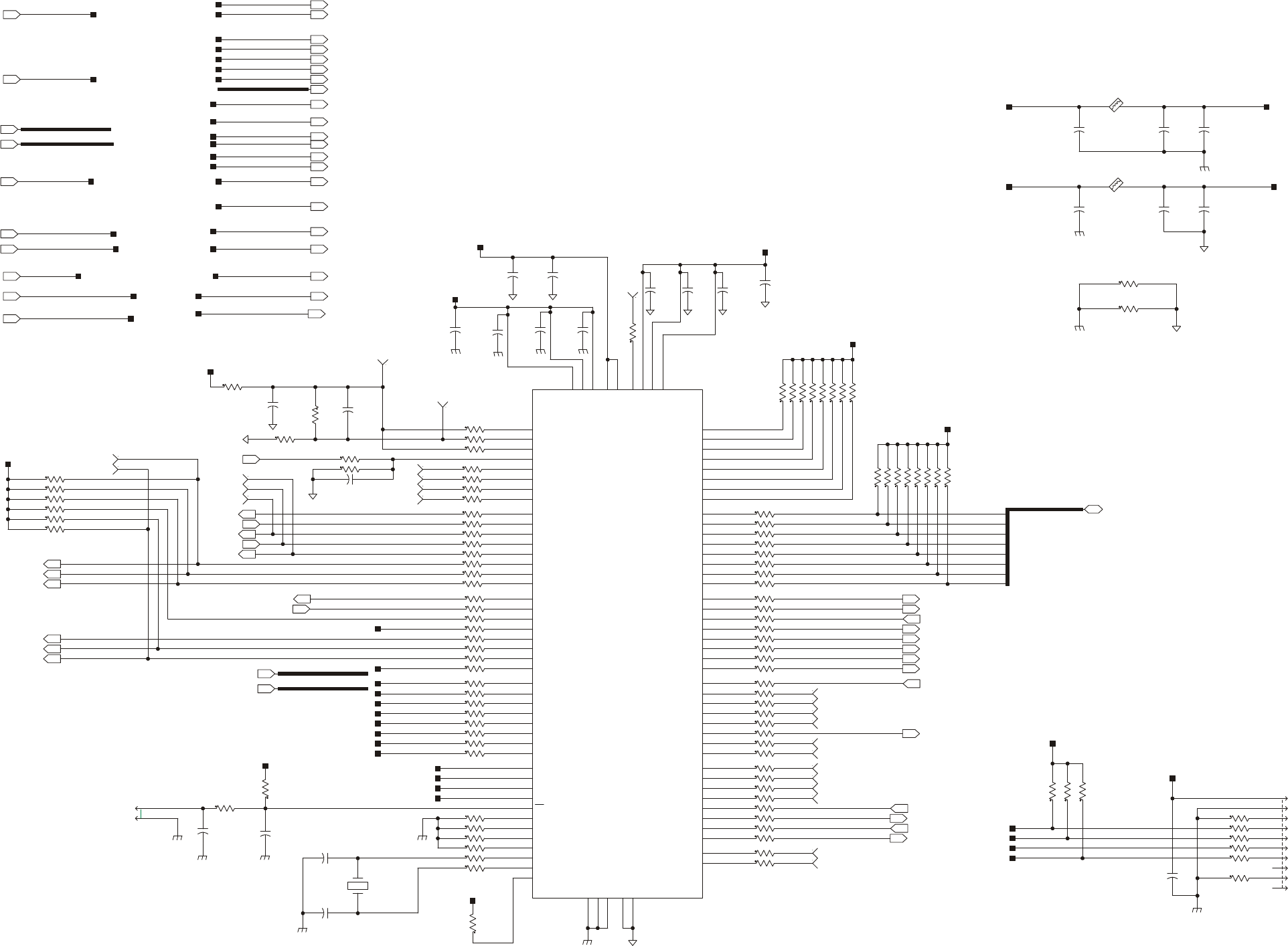
MM-E 2072-09333-00
~WR/P0.7
~RD/P0.6
ALE/P0.5
P0.4
P0.3
P0.2
P0.1
~WR/P4.7
~RD/P4.6
ALE/P4.5
P4.4
P4.3
P4.2
P4.1
A14/P5.6
A13/P5.5
A12/P5.4
A11/P5.3
A10/P5.2
A9/P5.1
A15M/A7/P6.7
A14M/A6/P6.6
A13M/A5/P6.5
A12M/A4/P6.4
A11M/A3/P6.3
A10M/A2/P6.2
A9M/A1/P6.1
AD6/D6/P7.6
AD5/D5/P7.5
AD4/D4/P7.4
AD3/D3/P7.3
AD2/D2/P7.2
AD1/D1/P7.1
AD6/D6/P3.6
AD5/D5/P3.5
AD4/D4/P3.4
AD3/D3/P3.3
AD2/D2/P3.2
AD1/D1/P3.1
A14M/A6/P2.6
A13M/A5/P2.5
A12M/A4/P2.4
A11M/A3/P2.3
A10M/A2/P2.2
A9M/A1/P2.1
AIN2.6/A14/P1.6
AIN2.5/A13/P1.5
AIN2.4/A12/P1.4
AIN2.3/A11/P1.3
AIN2.2/A10/P1.2
AIN0.6
AIN0.5
AIN0.4
AIN0.3
AIN0.2
AIN0.1
AIN0.0
AIN0.7
AIN2.7/A15/P1.7
A8M/A0/P2.0
AD0/D0/P3.0
AD7/D7/P3.7
AD0/D0/P7.0
A8M/A0/P6.0
A8/P5.0
A15/P5.7
AD7/D7/P7.7
DAC0
DAC1
AIN2.1/A9/P1.1
AIN2.0/A8/P1.0
P0.0
A15M/A7/P2.7
TMS
TDI
TDO
RST
TCK
CP1+
CP1-
CP0-
CP0+
XTAL1
XTAL2
MONEN
DGND1
AGND1
AGND2
P4.0
VDD2
VDD1
VDD3
AV+1
AV+2
VREF
VREF0
VREF2
DGND2
DGND3
VREFD
T
ACTIVE HIGH
ACTIVE HIGH
GND
TCK
3V3
TDO
TMS
CPU_JTAG
TDI
ACTIVE HIGH
ACTIVE HIGH
REMAINS FROM INT0_N
ACTIVE HIGH = F(T,LED_ON)
RESET_CPU
ACTIVE HIGH
ACTIVE HIGH
ACTIVE LOW
ACTIVE LOW
1
E8
SH_DN_232_N
TAD_CODAN_MODE
SH_DN_232_N
TAD_CODAN_MODE
ON_OFF_SW
10KR100
R25
12.1K
3V3_CPU_AN
RT1
232261513103
100N
C555C554
100N
100N
C545
3V3_CPU
3V3_CPU_AN
TX_UART0_TTL
100N
C24C23
100N
55
56
57
58
59
60
61
91
92
93
94
95
96
97
82
83
84
85
86
87
73
74
75
76
77
78
79
66
67
68
69
70
71
48
49
50
51
52
53
40
41
42
43
44
45
30
31
32
33
34
24
23
22
21
20
19
18
25
29
46
54
47
72
80
88
81
65
100
99
35
36
62
39
1
3
4
5
2
7
6
8
9
26
27
28
38
10
13
98
64
37
90
11
14
12
16
17
63
89
15
U1
C8051F126-GQ
1
E3
TERMISTOR
TERM_M
50V
4.7U
C15
C16
4.7U
50V
C551
4.7U
50V
50V
4.7U
C27
100N
C22
C14
10U
25V
25V
10U
C552
3V3
3V3
E502
BLM18PG600SN1
R531 0.0
0.0625
3V3_CPU
3V3_CPU_AN
R584 0.0
100N
C25
1
E4
V0_LCD
XCS_N_SDF
R37 1M
BLM18PG600SN1
E26
RX_UART0_TTL
RX_UART1_TTL
100N
C32
A0_CPU
MOSI_CPU
XCS_N_LCD
RST_N_LCD
RD_N_CPU
WR_N_CPU
R105 10K
R36 22.1
22.1R91
R506 22.1
LAB
CPU_D6
CPU_D5
CPU_D4
CPU_D3
CPU_D2
CPU_D1
CPU_D0
CPU_D[7:0]
CPU_D7
C46
100N
16V
R92 22.1
1
TP501
R21 22.1
22.1R22
22.1R23
R46 22.1
22.1R45
R44 22.1
R43 22.1
22.1R42
1
E14
1
E15
1
E16
1
E17 22.1R40
R41 22.1
22.1R38
R39 22.1
C47
1U
10V
1
E7
R71 22.1
22.1R72
ON_OFF_SW
POW_OFF_CPU
PTT_MIC_P_CPU
PTT_MIC_N
VLED_HEAT_EN
KB_BL_EN
RX_UART0_TTL
SCL_CPU
R80 22.1
LCD_HEAT_LEVEL
LCD_BL_LEVEL
LCD_BL_EN
R19 22.1
RX_UART1_TTL
TX_UART1_TTL
0.0R82
R83 0.0
0.0R84
R85 0.0
0.0R86
R81 0.0
10KR121
9
8
7
6
5
4
3
2
10
1
TSW-105-23-S-D
P5
1
E2
1
E1
1
E9
1
E5
R49 22.1
R18
100K
R17
1K
1
2
P7
TSW-102-23-S-S
R212 221K
C121
100N
1
E25
1
E24
KEY_X0
KEY_X1
KEY_X4
KEY_X[4:0]
KEY_Y0
KEY_Y[4:0]
22.1R63
R120 10K
10KR119
10KR98
R99 10K
R93 10K
22.1R223
R222 22.1
22.1R54
R115 22.1
Y1
7.3728MHZ
33P
C19
MISO_CPU
22.1R26
1
E21
1
E22
22.1R65
R87
10K
R107 10K
10KR106
22.1R116
R114 22.1
22.1R117
TCK_CPU
3V3_CPU
R62 22.1
R51 22.1
100N
C26
C20
33P
22.1R33
R32 22.1
R31 22.1
22.1R30
22.1R29
R28 22.1
R27 22.1
3V3_CPU
R47 22.1
22.1R48
22.1R50
22.1R52
R53 22.1
22.1R61
R60 22.1
R59 22.1
R58 22.1
22.1R57
22.1R56
22.1R55
R70 22.1
R69 22.1
R68 22.1
22.1R67
22.1R66
R64 22.1
R74 22.1
R73 22.1
R76 22.1
R75 22.1
R78 22.1
R77 22.1
R79 22.1
3V3_CPU
10KR108
3V3_CPU
R109 10K
10KR110
1
E23
TDO_CPU
3V3_CPU
TMS_CPU
TDI_CPU
3V3_CPU
10KR94
R95 10K
10KR96
R97 10K
R118 10K
10KR113
R112 10K
10KR111
R104 10K
10KR103
R102 10K
10KR101
22.1R20
R24 22.1
22.1R34
R35 22.1
22.1R88
R89 22.1
22.1R90
KEY_Y3
KEY_Y2
KEY_Y1
KEY_X3
KEY_X2
C45
100N
1
E10
1
E11
3V3_CPU
1
E32
1
E36
1
E35
1
E33
PTT_MIC_P_CPU
XCS_N_SDF
XIL_MONITOR3V3
SDF_SW_DET
TX_UART1_TTL
KEY_X[4:0]
KEY_Y[4:0]
CPU_D[7:0]
WR_N_CPU
RST_N_LCD
XCS_N_LCD
RD_N_CPU
SCL_CPU
MOSI_CPU
V0_LCD
MISO_CPU
XIL_MONITOR
LCD_HEAT_LEVEL
LCD_BL_LEVEL
LCD_BL_EN
KB_BL_EN
SDF_SW_DET
VLED_HEAT_EN
LCD_HEAT_EN
KEY_Y4
C553
100N
TX_UART0_TTL
LCD_HEAT_EN
A0_CPU
1N
C550
0.0625
0.0R532
C544
4.7U
50V
TCK_CPU
TDO_CPU
TDI_CPU
TMS_CPU
MR_N
V0_LCD_DIV
3V3_CPU_AN
POW_OFF_CPU
Figure A-3.B. CONTROL HEAD Module, Schematic Circuit Diagram (Sheet 2 of 6 – Microcontroller)
A-53/A-54
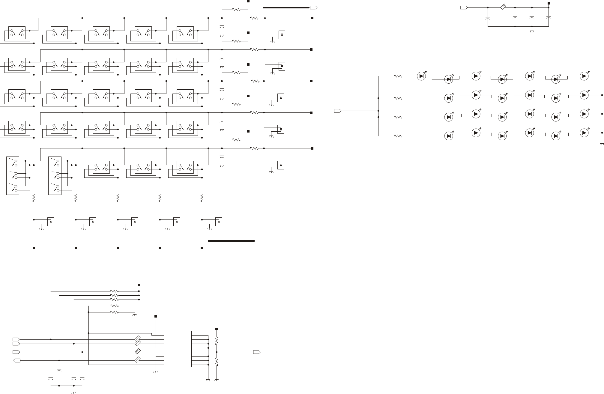
MM-E 2072-09333-00
GND10
GND9
GND8
GND7
GND5
GND2
DAT1
DAT0
VSS
CLK
VDD
CMD
DAT2
CD/DAT3
GND1
GND6
+
-
+
-
+
-
+
-
+
-
+
-
+
-
+
-
+
-
+
-
KEYPAD
PAD6
1 2 3 4 5
ENTER VOL_UP
PAD2
VOL_DN
PAD2
6 7 8 9 0
M P * GPS #
PAD6
F1 F2 F3 F4
PAD4
PAD6
PAD6 !!!
ARRUP
PAD3
ARRDN
PAD3
MORE
PAD5
4V3
3
1
MMBZ5229BLT1
VR506
1
3
VR505
MMBZ5229BLT1
3
1
MMBZ5229BLT1
VR504
1
3
VR503
MMBZ5229BLT1
3
1
MMBZ5229BLT1
VR502
KEY_Y3
KEY_Y2
KEY_Y1
1
3
VR507
MMBZ5229BLT1
3
1
MMBZ5229BLT1
VR508
1
3
VR509
MMBZ5229BLT1
3
1
MMBZ5229BLT1
VR510
1
3
VR511
MMBZ5229BLT1
R122
150
C54
4.7U
50V
3V3
C53
10U
25V
150
R123R124
150150
R125R126
150
12
11
10
9
15
14
8
7
6
5
4
3
1
2
13
16
J4
DM3A-SF-PEJ
100N
C59
R529
1.10K
R533
1.10K
R563
1.10K
R569
1.10K
R583
1.10K
KEY_X0
KEY_X1
KEY_X2
KEY_X3
R141
20K
20K
R140
R139
20K
20K
R138
R137
20K
KEY_X[4:0]
3V3_IF
1
2
3
4
SW25
PAD_SW_KEY2
1
2
3
4
SW24
PAD_SW_KEY2
1
2
3
4
SW23
PAD_SW_KEY6
6
5
4
3
2
1
PAD_SW_KEY3
SW22
1
2
3
4
5
6
SW21
PAD_SW_KEY3
4
3
2
1
PAD_SW_KEY5
SW20
4
3
2
1
PAD_SW_KEY4
SW19
4
3
2
1
PAD_SW_KEY4
SW18
4
3
2
1
PAD_SW_KEY4
SW17
4
3
2
1
PAD_SW_KEY4
SW16
4
3
2
1
PAD_SW_KEY6
SW15
4
3
2
1
PAD_SW_KEY6
SW10
4
3
2
1
PAD_SW_KEY6
SW5
4
3
2
1
PAD_SW_KEY6
SW4
4
3
2
1
PAD_SW_KEY6
SW9
4
3
2
1
PAD_SW_KEY6
SW14
4
3
2
1
PAD_SW_KEY6
SW13
4
3
2
1
PAD_SW_KEY6
SW8
4
3
2
1
PAD_SW_KEY6
SW3
4
3
2
1
PAD_SW_KEY6
SW2
4
3
2
1
PAD_SW_KEY6
SW7
4
3
2
1
PAD_SW_KEY6
SW12
4
3
2
1
PAD_SW_KEY6
SW11
4
3
2
1
PAD_SW_KEY6
SW6
1
2
3
4
SW1
PAD_SW_KEY6
3V3_IF
3V3_IF
3V3_IF
100P
C61C62
100P
3V3_IF
3V3_IF
100P
C64 C63
100P
3V3_IF
C65
100P
R133
10K
R146 51.1K
E29
BLM18BB750SN1D
22P
C69
C68
22P
C67
22P22P
C66
R148 OPTION
R147
OPTION
51.1KR145
R144 51.1K
BLM18BB750SN1D E28
E27
BLM18BB750SN1D
BLM18BB750SN1D E20
51.1KR143
SDF_SW_DETSCL_CPU
MOSI_CPU
XCS_N_SDF
MISO_CPU
KEY_Y0
3V3_IF
3V3_IF
100N
C60
BLM18PG600SN1
E19
KEY_Y[4:0]
KEY_Y4
KEY_X4
14V7
R233 41.2
1 2
DS12
KPT-1608CGCK-RY
1 2
DS13
KPT-1608CGCK-RY
150R128
R127 150
150R142
VLED_BL_KB
1 2
DS1
KPT-1608CGCK-RY
1 2
DS14
KPT-1608CGCK-RY
1 2
DS20
KPT-1608CGCK-RY
1 2
DS8
KPT-1608CGCK-RY
1 2
DS2
KPT-1608CGCK-RY
1 2
DS15
KPT-1608CGCK-RY
1 2
DS21
KPT-1608CGCK-RY
1 2
DS9
KPT-1608CGCK-RY
1 2
DS3
KPT-1608CGCK-RY
1 2
DS4
KPT-1608CGCK-RY
1 2
DS10
KPT-1608CGCK-RY
1 2
DS16
KPT-1608CGCK-RY
1 2
DS22
KPT-1608CGCK-RY
1 2
DS5
KPT-1608CGCK-RY
1 2
DS11
KPT-1608CGCK-RY
1 2
DS23
KPT-1608CGCK-RY
1 2
DS17
KPT-1608CGCK-RY
1 2
DS6
KPT-1608CGCK-RY
1 2
DS18
KPT-1608CGCK-RY
1 2
DS24
KPT-1608CGCK-RY
1 2
DS7
KPT-1608CGCK-RY
1 2
DS19
KPT-1608CGCK-RY
1 2
DS25
KPT-1608CGCK-RY
Figure A-3.C. CONTROL HEAD Module, Schematic Circuit Diagram (Sheet 3 of 6 – Keypad)
A-55/A-56
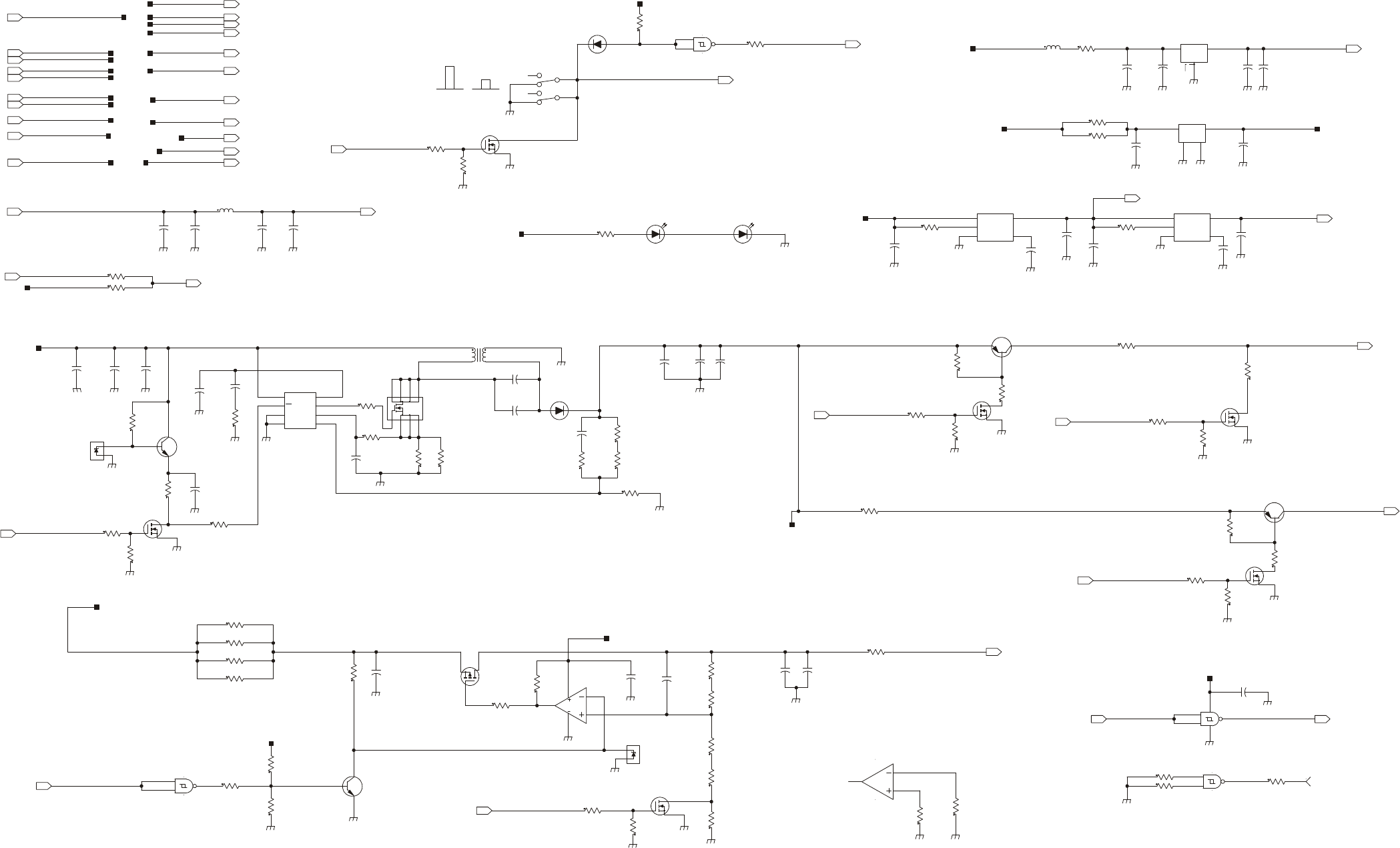
MM-E 2072-09333-00
+
-
GND
VCC
EN
GND
RBP
VIN
VOUT
V
V
VIN
SD
PGND
AGND FB
COMP
ISEN
DR
S
D
D
D
G
SD
S
D
S
G
GND
GND
IN
OUT
SD
G
EN
GND RBP
VIN VOUT
+
-
+
+
+
+
GND
IN
OUT
2
D
S
G
D
S
G
TRUNK ONLY
TRUNK ONLY
4V3
2+1 2+3
5+6
ACTIVE HIGH
'1'=>9V0
'0'=>6V3
5+4
ACTVIVE LOW
ACTIVE HIGH
ACTVIVE HIGH
ACTIVE GND
TO CPU
.5W
4V3
14V7
NEW LEDS
ACTVIVE HIGH
1W
ON_OFF_CONT
R603 51.1
R537 51.1
14V7
LCD_HEAT_EN
1W
33.2
R204
33.2
R539
POW_OFF_CPU
VHEAT_LCD_FOR
R167
475
0.125
R159
5.11K
0.125
3
1
2
Q501
BST82
R517
100
R509
100
3
1
2
Q506
BST82
U6_FB
100
R508
511
R512
R602
511
R520
100
D
S
G
2
1
3
D
S
G
2
1
3
BST82
Q502
Q505
BST82
4
1 3
U502
MC78M08BDTRK
VLED_BL_LCD
10K
R522
LCD_BL_LEVEL
R541
86.6
10K
R523
5V0
PTT_MIC_P
VDD_LCD_3V0
14V7
VLED_BL_KB
13V8_DC
5V0_INT
C85
4.7U
50V
C76
4.7U
50V
C73
4.7U
50V
C97
4.7U
50V
C72
4.7U
50V
C71
4.7U
50V
8V0_AUDIO
C507
10U
25V
C510
15U
16V
C80
1U
100V
VLED_HEAT_EN
L501
10U
C81
100N
50V
50V
100N
C86
50V
100N
C95
C508
100N
25V
C512
22U
35V
MMSD4148T1
CR501
R530 33.2
1W
25V
15U
C99
13V8_DC
C98
15U
25V
13V8_RADIO_TRUNK
C84
15U
25V
100V
1U
C511
3V3
5V0_INT
R177
0.0
1.10K
R515
14V7_CONT3
33.2R201
VHEAT_LCD
R152
0.0
R178
3.01K
R155
0.0
R160
511
R197
31.6K
C90
100P
C83
47U
35V
C79
47U
35V
R519
10K
R536
8.25K
0.125
R581
2.67K
0.125
R158
4.75K
0.125
1
3
VR1
MMBZ5229BLT1
R157
3.01K
0.125
C82
1U
100V
13V8_RADIO_TRUNK
3
2 4
1 5
U4
LP3985IM5-3.3
L8
33UH
R540
20
ON_OFF_SW
R528
10K
3V3
2
3
1
Q504
MMBT4403LT3
D
S
G3
1
2
Q507
BST82
R507
100
VLED_BL_LCD
4
1
3
Q1
IRFR9220
R186
10K
2 4
1 3
U501
LM2940SX-5.0
POW_OFF_CPU
10
R166
13V8_DC
1K
R514
10K
R527
R526
10K
LAB
3V3
R516
3.01K
3
12
Q7
BST82
C89
100N
100N
C87
100N
C88
5
6
7
8
3
2
1
4
Q2
SI4450DY-TR
R156
5.1
0.1
R196
14V7_CONT2
C509
100N
10K
R524
LCD_HEAT_EN
VLED_BL_KB
8V0_AUDIO
VHEAT_LCD
PTT_MIC_P
R151 100
40.2R538
5V0
R170 33.2
LCD_BL_EN
2
31
Q503
MMBT4403LT3
3V3
14V7
R194
30.1K
7
8
14
10
9
74HC132D
U3
7
11
14
13
12
74HC132D
U3
2
1
3
5
4
6
SW26
MHPS2266
VDD_LCD_3V0
5V0
8
7
5
4 3
2
1
6
U6
LM3488MM
C92
100N
R226 10
CR2
MBRS360T3
4
5
14
6
7
U3
74HC132D
2
34
1
22U
T1
33.2
R203
PTT_MIC_N
3
2
1
8
4
U7
LM2903D
R195
0.1
C93
100N
R187
10K
R193
4.12K
C96
22P
3
2 4
1 5
U5
LP3985IM5X-3.0
C78
100N
1
2
7
14
3
U3
74HC132D
1
3
2
Q3
MMBT2222ALT1
C94
220P
C91
100N
1
3
VR2
MMBZ5229BLT1
1
3
2
Q4
MMBT2222ALT1
R198
4.75K
6
5
7
48
U7
LM2903D
R207
5.11K
R206
5.11K
1
TP3
R221 10
10R220
33.2
R202
ON_OFF_CONT
3V3
13V8_DC
PTT_MIC_N
LCD_BL_EN
LCD_BL_LEVEL
LCD_HEAT_LEVEL
KB_BL_LEVEL
KB_BL_EN
5V0
10K
R518
R513
1K
R521
10K
10K
R525
R535 0.0
0.0R534
C513
100N
LCD_HEAT_LEVEL
ON_OFF_SW
5V0_RADIO
5V0_RADIO
KB_BL_EN
50V
4.7U
C70
50V
4.7U
C74
1 2
DS27
KPT-1608CGCK-RY
1 2
KPT-1608CGCK-RY
DS26
13V8_DC
Figure A-3.D. CONTROL HEAD Module, Schematic Circuit Diagram (Sheet 4 of 6 – Power Supply Circuits)
A-57/A-58
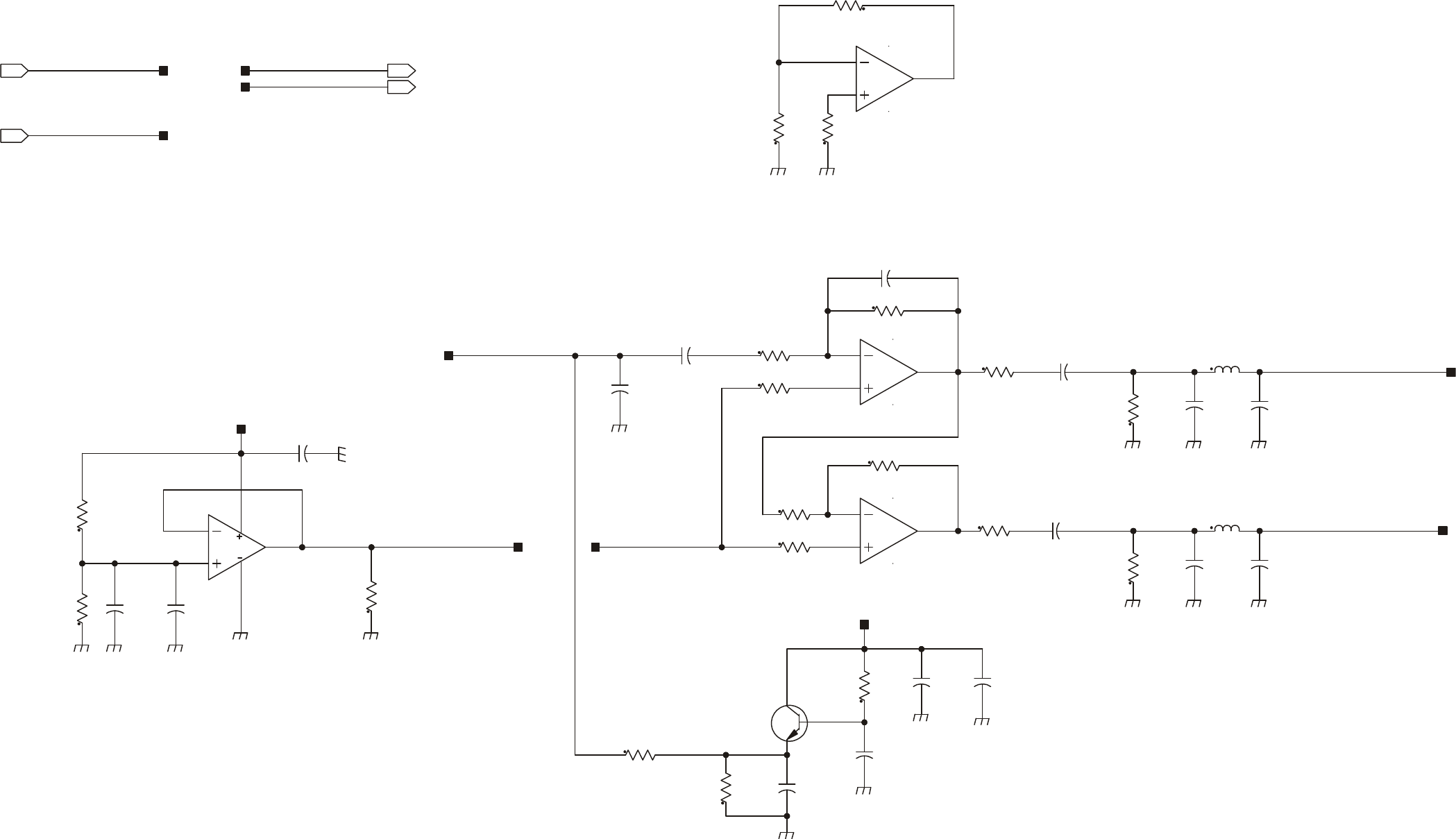
MM-E 2072-09333-00
V
V
+
+
+
C522
10U
25V
C523
10U
25V
C521
10U
25V
C525
4.7U
10V
10V
4.7U
C526
11
7
5
6
4
MC33174DR2
U503
11
1
3
2
4
MC33174DR2
U503
1
2
3
Q508
MMBT2222ALT1
C519
33U
10V
C529
100N
16V
AUDIO_BIOS
MIC_IN
8V0_AUDIO
AUDIO_BIOS
8V0_AUDIO
8V0_AUDIO
TX_AUDIO_M
TX_AUDIO_P
TX_AUDIO_M
TX_AUDIO_P
1N
C518
C514
1N
10K
R548
20K
R552
11
8
10
9
4
MC33174DR2
U503
R556
562
C524
470N
MIC_IN
12
13
14
4
11
U503
MC33174DR2
20K
R555
R554
20K
R559
2.74K
100N
C528
R553
20K
20K
R551
274
R558
10K
R550
R549
10K 100N
C527
R547 10K
R543
1K
R557
274
10K
R546
R545
10K
10K
R544
R560
4.75K
C520 330P
1K
R542
1N
C517
L502
4.7U
1N
C516C515
1N
L503
4.7U
Figure A-3.E. CONTROL HEAD Module, Schematic Circuit Diagram (Sheet 5 of 6 – Audio Amplifier, Trunk Mount Version Only)
A-59/A-60
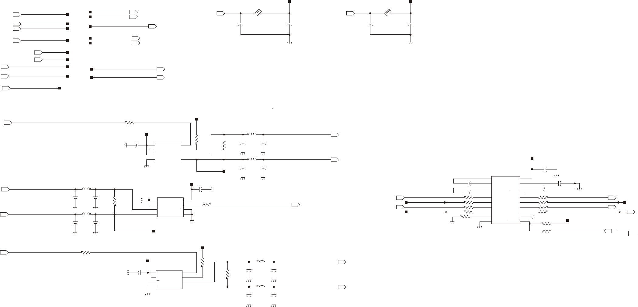
MM-E 2072-09333-00
DI VCC
RO
DE
RE
GND
A
B
DI
VCC
RO DE
RE
GND
A
B
DI
VCC
RO DE
RE
GND
A
B
ACTIVE
ACTIVE
10 0
0
SHDN
OPSTATUS
AUTOSHDN
FORCEON
0X
0 1
EN_N
0
T_OUTF_OFF_N R_OUT
ACTIVE
VALID
X
YES
NO
HIGH_Z
HIGH_Z HIGH_Z
NORMAL (AUTOSHDN)
(PTP_TXD)
(PTP_RXD)
ACTIVE LOW
SH_DN_232_N
5V0_RS
5V0_RS
CH_TXD_P_INT
5V0_RS
5V0_RS
5V0_RS
E601
BLM18PG600SN1 BLM18PG600SN1
E501
TX_UART0_TTL
3V3_UART
48
1 3
2
5
6
7
U505
LTC485IS8
CH_TXD_P
C530
10U
25V
L506
4.7U
4.7U
L508
CH_RXD_P_INT
1K
R565
RXD
RX_UART1_TTL
TXD
1K
R561
PTT_MIC_P
CH_RXD_P
CH_RXD_M
R580
10
R564
1K
48
1 3
2
5
6
7
U506
LTC485IS8
R567
1K
10
R579
C558
100N
180P
C536C535
180P
180P
C533C534
180P
C531
180P
180P
C532
TRUNK_RX_UART0_TTL
7
6
5
2
3 1
84
LTC485IS8
U504
3V3
5V0
4.7U
L509
L507
4.7U
1K
R566
100N
C559
R578
10
100N
C557
4.7U
L505
L504
4.7U
PTT_M
PTT_P
CH_TXD_M
TRUNK_RX_UART0_TTL
CH_RXD_P
PTT_P
PTT_MIC_P
TX_UART0_TTL CH_TXD_P
CH_TXD_M
PTT_M
CH_RXD_M
100N
C543
3V3
180P
C538 C537
180P
180P
C540C539
180P
180P
C542
C541
180P
TX_UART1_TTL
5V0
C602
100N
25V
10U
C601
5V0_RS
C2-
C2+
C1+
V+
C1-
T1I
V-
R1O
T1O
VCC
GND
FORCEON
FORCEOFF
INVALID
T2I
T2O
R1I
R2I
R2O
RDY
ACTIVE LOW
R570-573-OPTION FOR TRUNK/CDN/UART1-UART0 MODE
6
5
2
34
13
7
15
17
19
18
14
20
11
12 8
16
9 10
1
U507
MAX3224EEAP
SH_DN_232_N
3V3_UART
R57610
10R572
TX_UART0_TTL
TX_UART1_TTL
PTP_RXD
PTP_TXD
CH_TXD_P_INT
RX_UART1_TTL
TRUNK_RX_UART0_TTL
CH_RXD_P_INT
100NC548
C546 100N
C556 100N
C547 100N
100NC549
10 R570
R57110
10KR568
R573 10
1K R562
10 R57510R577
R574 10
3V3_UART
10 R604
Figure A-3.F. CONTROL HEAD Module, Schematic Circuit Diagram (Sheet 6 of 6 – Interface Circuits, Trunk Mount Version Only)
A-61/A-62
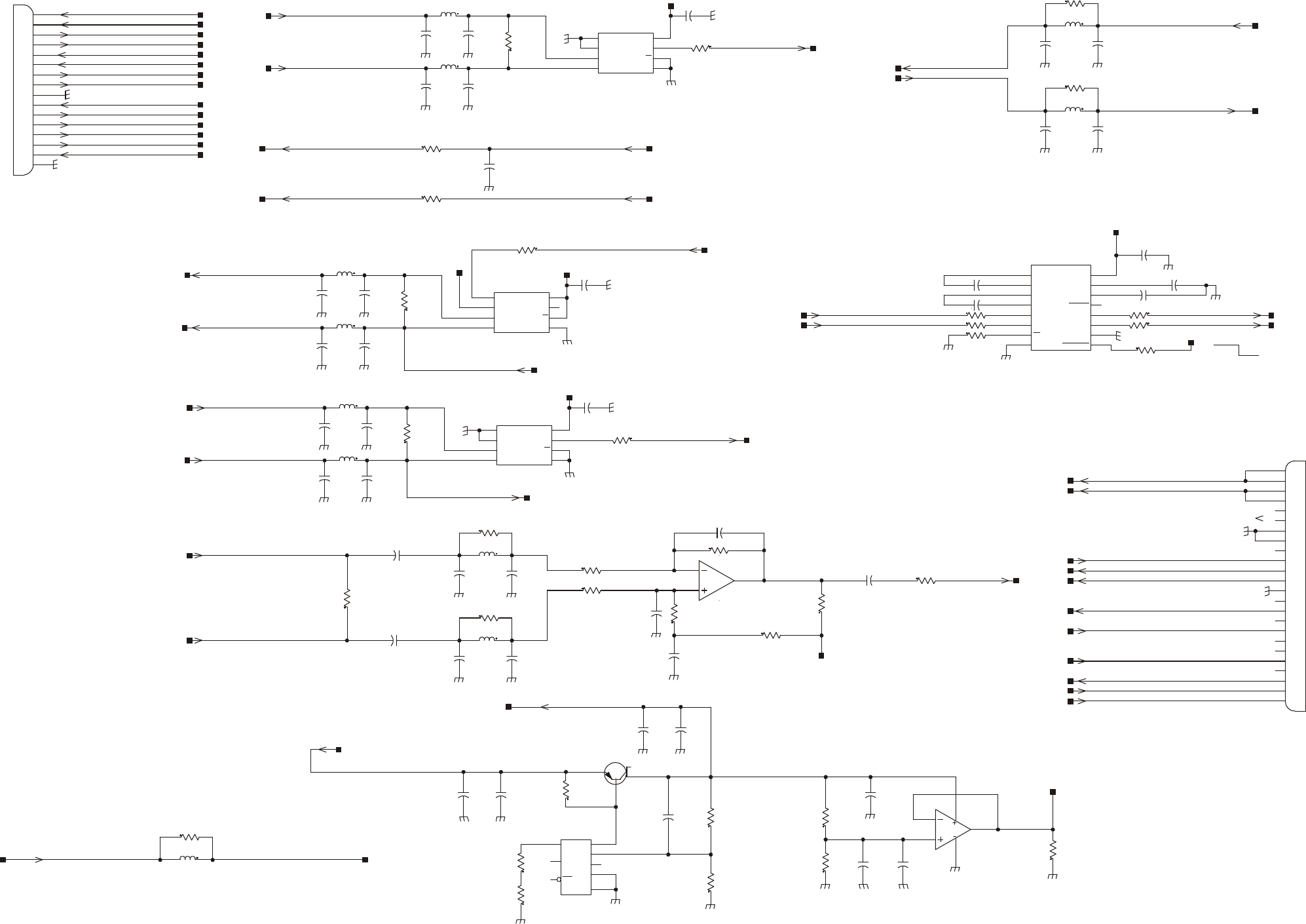
MM-E 2072-09333-00
DI VCC
RO
DE
RE
GND
A
B
5VTAP
FDBCK
GND
IN
OUT
SENS
STDN
ERR
DI
VCC
RO
DE
RE
GND
A
B
DI
VCC
RO
DE
RE
GND
A
B
V
V
C2-
C2+
C1+
V+
C1-
T1I
V-
R1O
EN
T1O
VCC
GN D
FORCEON
FORCEOF F
R1I
INVALID
N
O
T
A
S
S
E
M
B
L
E
D
I
N
D
A
S
H
M
O
D
E
ACTIVE
ACTIVE
10 0
0
SHDN
OPSTATUS
AUTOSHDN
FORCEON
0X
0 1
EN_N
0
T_OUTF_OFF_N R_OUT
ACTIVE
VALID
X
YES
NO
HIGH_Z
HIGH_Z HIGH_Z
NORMAL (AUTOSHDN)
ONLY ASSEMBLED IN CDN MODE
RADIO_DASH_TO_FROM
RX_AUDIO_PRADIO ONLY
PANEL_TO_FROM
C36
100N
13V8_RADIO_TRUNK
13V8_RADIO_TRUNK
22U
L9
C40 100N
LAB
100NC41
6
5
2
34
11
7
9
1
13
15
14
12
16
8
10
U6
MAX3221EEUE+
LAB
C43 470N
470N C45
C44 470N
10KR33
LAB
10 R35
LAB
R3410 LAB
1K R32
LAB
10
R37
LAB
R36 10
LAB
CH_TXD_P_INT
RADIO_RX_UART0_TTL
CH_RXD_P_INT
180P
C25
56.2KR17
R2
261
13V8_DC_RADIO
1
2
4
3
Q1
D45H8
16
10
11
12
13
14
2
3
4
5
6
7
8
9
1
15
P2
43045-1618
PANEL_TO_FROM
CH_RXD_P
CH_RXD_M
AUDIO_BIAS_T
2
3
1
4
8
U1
MC33072ADR2
5
6
7
8
4
U1
MC33072ADR2
5V0
5V0
PTT_P
7
6
5
2
3 1
84
LTC485IS8
U4
RADIO_RX_UART0_TTL
TX_UART0_TTL
TX_UART0_TTL
CH_RXD_P_INT
TX_UART0_TTL
PTP_RXD_PNL
PTP_TXD_PNL
PTT_MIC_POS
RADIO_RX_UART0_TTL
PTT_M
R20 100K
R23
10
CH_TXD_M
CH_TXD_P
CH_TXD_P_INT
C42
1U
100V
7
6
5
2
3 1
84
LTC485IS8
U3
5V0
R26
2.67K
0.125
562
R1
R24
10
PTP_RXD
PTP_TXD
R9 10K
R14
10K
22U
L8
25V
10U
C30
C31
10U
25V
C10
1N
C8
1N
R6
1K
C32
10N
67
4
81
2
3
5
U2
LP2951CMX
C1
390N R15 20K
R21
1.82K
1%
1W
1%
15.4K
R3
R27
562
1/2W
R7
61.9
0.125W
R19
20K
R16
20K
390N
C4
C7 1N
C3
390N
L7
22U
R25
10
PTT_P
C37
100N
100N
C38
L2
4.7U
C33
100N
180P
C21C20
180P
C19
180P180P
C18
4.7U
L1
5V0
L4
4.7U
1K
R4
C34
100N
C24
180P
C23
180P180P
C22
4.7U
L3
7
6
5
2
3 1
84
LTC485IS8
U5
L6
4.7U
1K
R5
C35
100N
180P
C29C28
180P
C27
180P180P
C26
4.7U
L5
5V0
0.125
0.0R30
R29 0.0
0.125
INT_SPKR1_2_M
1N
C6
SPKR1_2_P
SPKR_M
SPKR_P
390N
C2
R22 43.2K
20K
R18
10K
R8
390N
C5
1N
C9
1N
C11
10KR10
10K
R11
22U
L10
C15
1N1N
C14
10KR12
22U
L11
C17
1N1N
C16
10KR13
C39
1N
13V8_RADIO_TRUNK
ON_OFF_CONT_PNL
PTP_TXD_PNL
CH_TXD_P
CH_TXD_M
CH_RXD_M
CH_RXD_P
PTP_RXD_PNL
TX_AUDIO_M
SPKR_P
SPKR_M
PTT_M
TX_AUDIO_P
MIC_IN
AUDIO_BIAS_T
TX_AUDIO_M
TX_AUDIO_P
1
10
11
12
13
14
15
16
17
18
19
2
20
21
22
23
24
3
4
5
6
7
8
9
P1
104549-3
RADIO_DASH_TO_FROM
CH_TXD+
CH_RXD+
PTT_MIC_POS
5V0
PTP_TXD
PTP_RXD
ON_OFF_CONT
13V8_DC_RADIO
MIC_IN
SPKR1_2_P
INT_SPKR1_2_M
5V0
ON_OFF_CONT_PNL ON_OFF_CONT
Figure A-4. INTERCONNECTION Module, Schematic Circuit Diagram
A-69/A-64
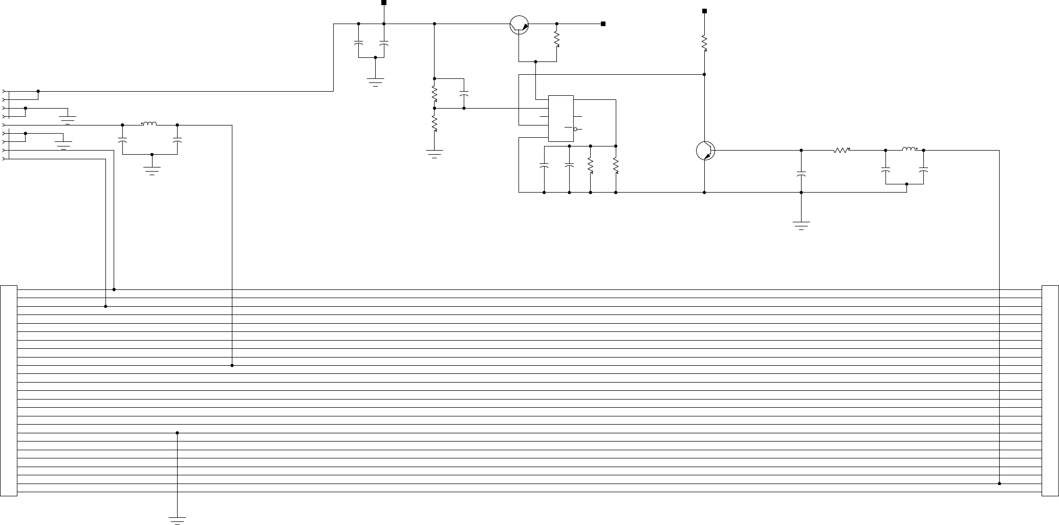
MM-E 2072-09333-00
+
5VTAP
FDBCK
GND
IN OUT
SENS
STDN
ERR
+
OUT_FROM_RADIO
IN_FROM_RADIO
L1
22U
1N
C3
1
43
Q2
MJD2955T4
SW_FAN
10N
C10
C6
2.2U
C4
1N
1N
C8
1
2
3
Q1
MMBT3904LT1
5
3
2
18
4
7
6
LP2951CMX
U1
L2
22U
1
2
3
4
5
6
7
8
9
J1
CD729S31D4
9
8
7
6
5
4
3
25
24
23
22
21
20
2
19
18
17
16
15
14
13
12
11
10
1
CD7225S31D4
J3
1
10
11
12
13
14
15
16
17
18
19
2
20
21
22
23
24
25
3
4
5
6
7
8
9
J2
CD7225S31D4
C2
1N
DSO/FAN_ON_OFF
12VDC
PTT_IN_CW
12VDC
CW
2.2U
C5
R2
1K
R4
511
R3
511
R7
56.2K
C9
10N
R5
10K
1N
C1
475
R6
470P
C7
110
R1
12VDC
SPKR+
SPKR-
Figure A-5. FAN CONTROL Module, Schematic Circuit Diagram
A-65/A-66

MM-E 2072-09333-00
B-1
Appendix B
PARTS LISTS
Section I. MICOM-Z DASH-MOUNT VERSION
Table B-1. Micom-Z Assembly Dash Version, Parts List
Ref. Des. Mfg. Catalog No.
Description Qty.
2072-90715-00 MICOM-Z ASSEMBLY, DASH Figure B-1
BL1 2072-95170-10 HI POWER MODULE 1.0
BL2 2072-90833-00 FRONT PANEL DASH ASSY 1.0
BL3 2072-90832-00 LORD ASSY 1.0
BL5 4053-10013-16 WASHER, SPRING, CRS, PASSIVATED, #10 1.0
BL6 4053-00037-16 WASHER, FLAT, CRS, PASSIVATED, .219 2.0
BL7 4051-00011-16 NUT, HEX, CRS, PASSIVATED, #10-32 1.0
BL8 2089-41660-00 KNOB 1.0
BL10 4053-10012-15 WASHER, SPRING, CRS, BLACK, #8 8.0
BL12 4053-16001-00 SPRING LOCK WASHERS, M3 11.0
BL13 2072-45002-10 REAR PANEL 1.0
BL16 2072-09296-00 CABLE COAX, LORD-H.P PA 2.0
BL17 2072-09295-00 CABLE, FLAT, LORD-H.P PA 1.0
BL18 2072-90160-00 CABLE, FLAT, TO CHASSIS 1.0
BL19 2072-90890-00 GPS ANTENNA TRANSITION 1.0
BL20 2072-34007-00 CABLE, FLAT, STRIP GPS 1.0
BL21 2072-90900-00 GPS CARD 1.0
BL22 4052-12019-88 SCREW, PH PHIL CRES, M 3X 9.0
BL23 2072-45011-00 BOX, MICOM-Z 1.0
BL24 4053-15002-00 WASHER, FLAT 9.0
BL25 2201-63202-03 HEATSINK COMPOUND, DC340 .200
BL26 2072-45041-00 LOCK PAD 2.0
BL27 4052-15003-00 SCREW, CROSS RECESSED, PAN HEAD 2.0
BL28 2072-90838-00 CONNECTOR ASSY, POWER 1.0
BL30 2072-45032-00 SCREW, M4X10, HEXAGON 8.0
BL31 2072-56022-00 SPACER FOR CONNECTOR SUB-D 4.0
BL32 4052-30011-16 SCREW, #10-32X3/4 1.0
BL33 2072-45042-00 PLUG COVER, D-TYPE, 9 PIN 1.0
BL34 2072-45031-00 SCREW, M3X4, FH, BLACK 8.0
BL35 2072-45013-00 COVER 1.0
BL37 2072-72707-00 PACKAGE BOX, DASH 1.0
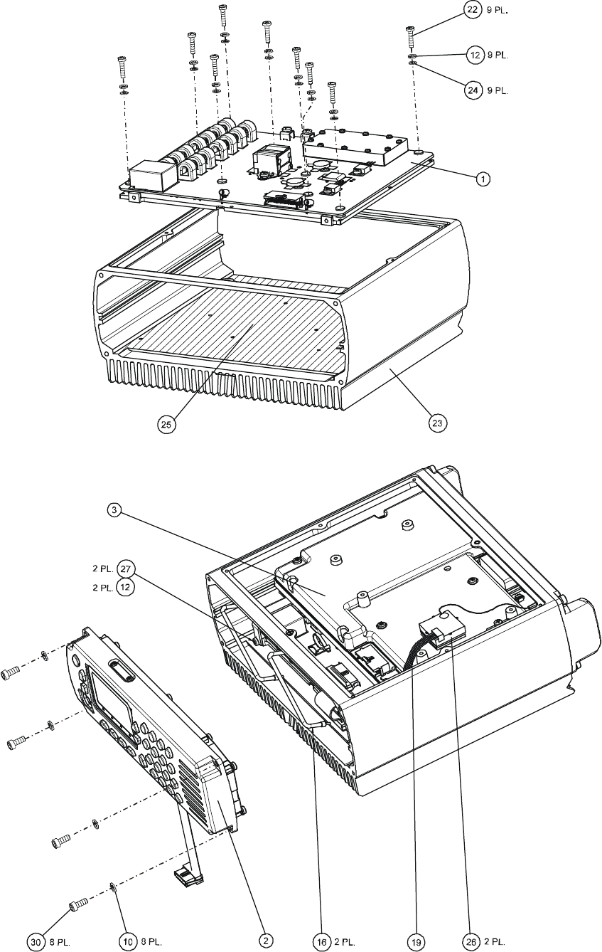
MM-E 2072-09333-00
B-2
Figure B-1.A. Micom-Z Assembly Dash Version (Sheet 1 of 2)
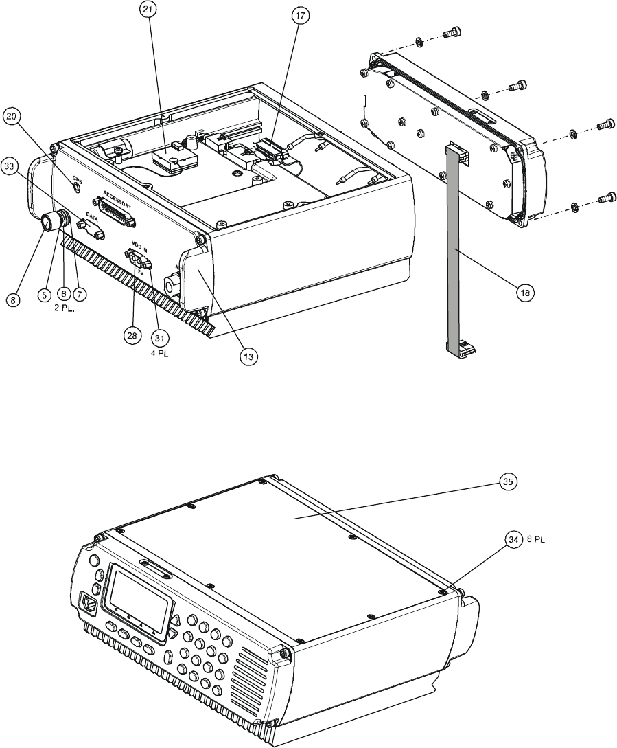
MM-E 2072-09333-00
B-3
Figure B-1.B. Micom-Z Assembly, Dash Version (Sheet 2 of 2)
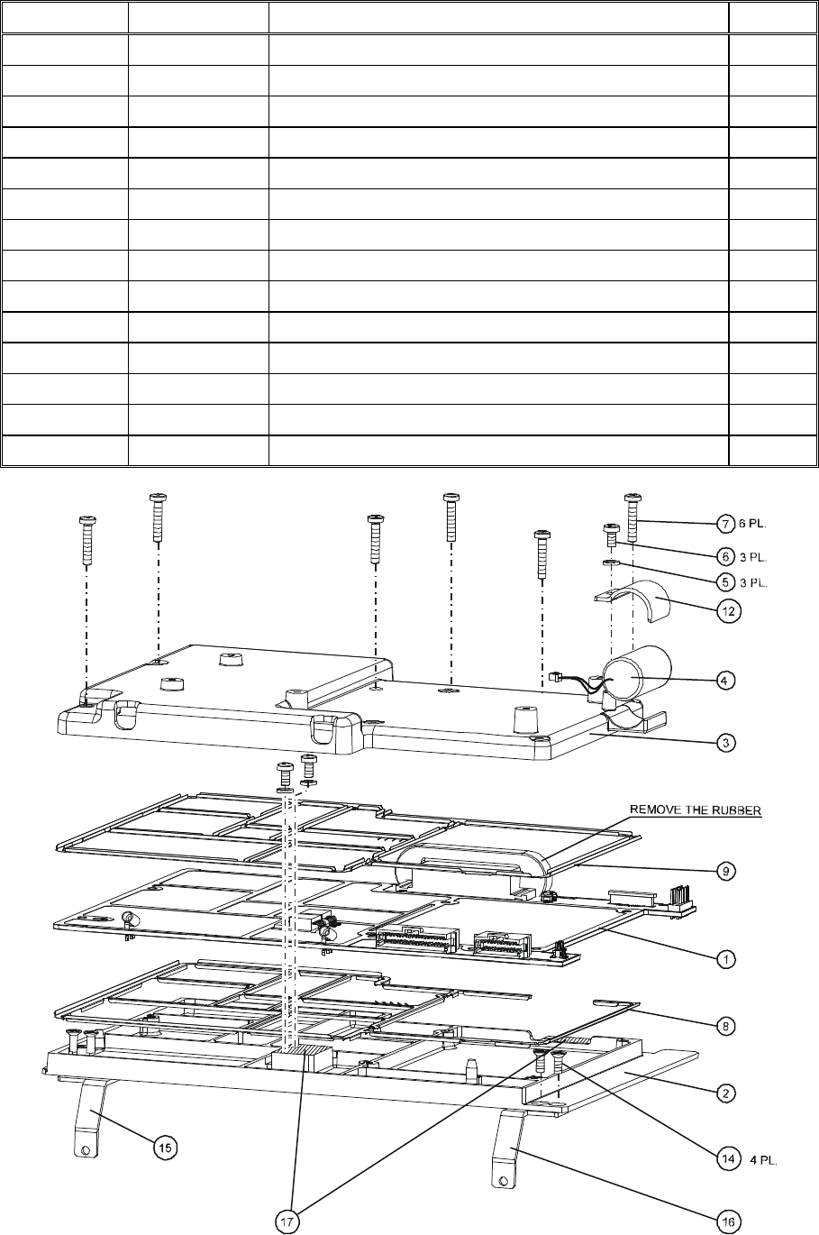
MM-E 2072-09333-00
B-4
Table B-2. LORD Assembly, Parts List
Ref. Des. Mfg. Catalog No.
Description Qty.
2072-90832-00 LORD ASSEMBLY Figure B-2
BL1 2072-95196-10
LORD MODULE 1.0
BL2 2072-48195-10
LORD PAD MACHINING 1.0
BL3 2072-48165-10
SHIELD HOUSING MACHINING 1.0
BL4 2072-90050-00
BATTERY ASSY, 0102703K64 1.0
BL5 4053-16001-00
WASHER, SPRING LOCK, M3 3.0
BL6 4052-15003-00
SCREW, CROSS RECESSED, PAN HEAD 3.0
BL7 2072-52004-00
SCREW, M3XP0.5X16 6.0
BL8 2072-40160-00
LOWER CONTACTS, 3904382P 1.0
BL9 2072-40150-00
UPPER CONTACTS, 3904381P 1.0
BL12 2072-48060-00
BATTERY HOLDER, LORD, MI 1.0
BL14 2072-45031-00
SCREW, M3X4, FH BLACK 4.0
BL15 2072-45018-00
HOLDER RIGHT, MICOM-Z 1.0
BL16 2072-45017-00
HOLDER LEFT, MICOM-Z 1.0
Figure B-2. LORD Assembly

MM-E 2072-09333-00
B-5
Table B-3. LORD Module, Parts List
Ref. Des. Mfg. Catalog No.
Description Qty.
2072-95196-10 LORD MODULE Figure B-3
BL1 2072-32200-50
PCB LORD 1.0
BL2 2072-41030-00
SPACER 2.0
BL3 4053-10010-16
WASHER, SPRING, CRS, PASSIVATED, #4 2.0
C1 2072-17107-00
CAPACITOR, TANTALUM, CHIP, 33UF, 16V 1.0
C2 2072-17107-00
CAPACITOR, TANTALUM, CHIP, 33UF, 16V 1.0
C3 2072-17105-00
CAPACITOR, TANTALUM, CHIP, 15UF, 25V 1.0
C4 4017-20284-00
CAPACITOR, CHIP, CERAMIC, 100NF, 16V 1.0
C6 4017-20284-00
CAPACITOR, CHIP, CERAMIC, 100NF, 16V 1.0
C7 4017-20284-00
CAPACITOR, CHIP, CERAMIC, 100NF, 16V 1.0
C8 4017-20284-00
CAPACITOR, CHIP, CERAMIC, 100NF, 16V 1.0
C9 4017-20284-00
CAPACITOR, CHIP, CERAMIC, 100NF, 16V 1.0
C10 4017-20284-00
CAPACITOR, CHIP, CERAMIC, 100NF, 16V 1.0
C11 4017-20284-00
CAPACITOR, CHIP, CERAMIC, 100NF, 16V 1.0
C12 4017-20284-00
CAPACITOR, CHIP, CERAMIC, 100NF, 16V 1.0
C13 4017-20284-00
CAPACITOR, CHIP, CERAMIC, 100NF, 16V 1.0
C14 4017-20284-00
CAPACITOR, CHIP, CERAMIC, 100NF, 16V 1.0
C15 4017-20284-00
CAPACITOR, CHIP, CERAMIC, 100NF, 16V 1.0
C16 4017-20284-00
CAPACITOR, CHIP, CERAMIC, 100NF, 16V 1.0
C17 4017-20284-00
CAPACITOR, CHIP, CERAMIC, 100NF, 16V 1.0
C18 4017-20284-00
CAPACITOR, CHIP, CERAMIC, 100NF, 16V 1.0
C19 4017-20284-00
CAPACITOR, CHIP, CERAMIC, 100NF, 16V 1.0
C20 4017-20284-00
CAPACITOR, CHIP, CERAMIC, 100NF, 16V 1.0
C21 4017-20284-00
CAPACITOR, CHIP, CERAMIC, 100NF, 16V 1.0
C22 4017-20284-00
CAPACITOR, CHIP, CERAMIC, 100NF, 16V 1.0
C23 4017-20284-00
CAPACITOR, CHIP, CERAMIC, 100NF, 16V 1.0
C24 4017-20284-00
CAPACITOR, CHIP, CERAMIC, 100NF, 16V 1.0
C25 4017-20284-00
CAPACITOR, CHIP, CERAMIC, 100NF, 16V 1.0
C26 4017-20284-00
CAPACITOR, CHIP, CERAMIC, 100NF, 16V 1.0
C27 4017-20271-00
CAPACITOR, CHIP, X7R, 10NF, 10% 1.0
C28 4017-20271-00
CAPACITOR, CHIP, X7R, 10NF, 10% 1.0
C29 2072-17032-00
CAPACITOR, CHIP, X7R, 3.3NF 1.0
C30 2072-17032-00
CAPACITOR, CHIP, X7R, 3.3NF 1.0
C31 4017-20267-00
CAPACITOR, CHIP, X7R, 4.7NF, 10% 1.0
C34 2072-17025-00
CAPACITOR, CHIP, X7R, 2.7NF 1.0
C36 2072-17025-00
CAPACITOR, CHIP, X7R, 2.7NF 1.0
C37 2072-17031-00
CAPACITOR, CHIP, X7R, 1.8NF 1.0
C38 2072-17031-00
CAPACITOR, CHIP, X7R, 1.8NF 1.0
C39 2072-17031-00
CAPACITOR, CHIP, X7R, 1.8NF 1.0
C40 2072-17031-00
CAPACITOR, CHIP, X7R, 1.8NF 1.0

MM-E 2072-09333-00
B-6
Table B-3. LORD Module, Parts List (Cont’d)
Ref. Des. Mfg. Catalog No.
Description Qty.
C41 2072-17031-00
CAPACITOR, CHIP, X7R, 1.8NF 1.0
C42 4017-20261-00
CAPACITOR, 0603, X7R, 1.5N, 50V 1.0
C43 4017-20261-00
CAPACITOR, 0603, X7R, 1.5N, 50V 1.0
C44 2072-17030-00
CAPACITOR, CHIP, X7R, 1.2NF 1.0
C45 4017-25282-00
CAPACITOR, CHIP, CG, 1NF, 5% 1.0
C46 4017-25282-00
CAPACITOR, CHIP, CG, 1NF, 5% 1.0
C47 4017-25282-00
CAPACITOR, CHIP, CG, 1NF, 5% 1.0
C48 2072-17029-00
CAPACITOR, CHIP, X7R, 680PF 1.0
C49 2072-17029-00
CAPACITOR, CHIP, X7R, 680PF 1.0
C50 2072-17029-00
CAPACITOR, CHIP, X7R, 680PF 1.0
C51 2072-17028-00
CAPACITOR, CHIP, X7R, 620PF 1.0
C52 4017-25279-00
CAPACITOR, CHIP, CG, 470PF, 5% 1.0
C54 4017-25279-00
CAPACITOR, CHIP, CG, 470PF, 5% 1.0
C56 4017-20085-00
CAPACITOR, CHIP, CERAMIC, X7R, 100NF 1.0
C58 2072-17026-00
CAPACITOR, CHIP, X7R, 6.8NF 1.0
C60 4017-25279-00
CAPACITOR, CHIP, CG, 470PF, 5% 1.0
C61 4017-25279-00
CAPACITOR, CHIP, CG, 470PF, 5% 1.0
C62 4017-25276-00
CAPACITOR, CHIP, CG, 270PF, 5% 1.0
C65 4017-25274-00
CAPACITOR, 0603, NP0 180P 50V 1.0
C66 4017-25269-00
CAPACITOR, 0603, NP0 68P, 50V 1.0
C67 4017-25269-00
CAPACITOR, 0603, NP0 68P, 50V 1.0
C72 4017-25276-00
CAPACITOR, CHIP, CG, 270PF, 5% 1.0
C77 2072-17056-00
CAPACITOR, CHIP, CL1, +/-30, 120P 1.0
C78 2072-17056-00
CAPACITOR, CHIP, CL1, +/-30, 120P 1.0
C79 4017-25081-00
CAPACITOR, CHIP, CERAMIC, C0G, 680PF 1.0
C80 4017-25075-00
CAPACITOR, CHIP, CERAMIC, C0G, 220PF 1.0
C81 4017-20271-00
CAPACITOR, CHIP, X7R, 10NF, 10% 1.0
C82 2072-17025-00
CAPACITOR, CHIP, X7R, 2.7NF 1.0
C83 4017-20284-00
CAPACITOR, CHIP, CERAMIC, 100NF, 16V 1.0
C84 4017-20284-00
CAPACITOR, CHIP, CERAMIC, 100NF, 16V 1.0
C85 4017-20284-00
CAPACITOR, CHIP, CERAMIC, 100NF, 16V 1.0
C86 4017-20284-00
CAPACITOR, CHIP, CERAMIC, 100NF, 16V 1.0
C87 4017-20284-00
CAPACITOR, CHIP, CERAMIC, 100NF, 16V 1.0
C88 4017-25062-00
CAPACITOR, CHIP, CERAMIC, C0G, 18PF 1.0
C89 4017-20284-00
CAPACITOR, CHIP, CERAMIC, 100NF, 16V 1.0
C90 4017-20284-00
CAPACITOR, CHIP, CERAMIC, 100NF, 16V 1.0
C91 4017-20284-00
CAPACITOR, CHIP, CERAMIC, 100NF, 16V 1.0
C92 4017-20271-00
CAPACITOR, CHIP, X7R, 10NF, 10% 1.0
C93 4017-20271-00
CAPACITOR, CHIP, X7R, 10NF, 10% 1.0
C94 2072-17030-00
CAPACITOR, CHIP, X7R, 1.2NF 1.0

MM-E 2072-09333-00
B-7
Table B-3. LORD Module, Parts List (Cont’d)
Ref. Des. Mfg. Catalog No.
Description Qty.
C95 4017-25279-00
CAPACITOR, CHIP, CG, 470PF, 5% 1.0
C96 4017-25279-00
CAPACITOR, CHIP, CG, 470PF, 5% 1.0
C97 4017-25279-00
CAPACITOR, CHIP, CG, 470PF, 5% 1.0
C98 4017-25279-00
CAPACITOR, CHIP, CG, 470PF, 5% 1.0
C99 4017-25279-00
CAPACITOR, CHIP, CG, 470PF, 5% 1.0
C100 2072-17032-00
CAPACITOR, CHIP, X7R, 3.3NF 1.0
C101 2072-17025-00
CAPACITOR, CHIP, X7R, 2.7NF 1.0
C102 2072-17025-00
CAPACITOR, CHIP, X7R, 2.7NF 1.0
C103 4017-25276-00
CAPACITOR, CHIP, CG, 270PF, 5% 1.0
C104 4017-25276-00
CAPACITOR, CHIP, CG, 270PF, 5% 1.0
C105 4017-25276-00
CAPACITOR, CHIP, CG, 270PF, 5% 1.0
C106 4017-25274-00
CAPACITOR, 0603, NP0, 180PF, 50V 1.0
C107 2072-17009-00
CAPACITOR, CHIP, 1206, 390PF, 5% 1.0
C108 2072-17009-00
CAPACITOR, CHIP, 1206, 390PF, 5% 1.0
C109 2072-17056-00
CAPACITOR, CHIP, CL1, +/-30, 120P 1.0
C110 4017-25075-00
CAPACITOR, CHIP, CERAMIC, C0G, 220PF 1.0
C111 4017-25282-00
CAPACITOR, CHIP, CG, 1NF, 5% 1.0
C112 4017-20284-00
CAPACITOR, CHIP, CERAMIC, 100NF, 16V 1.0
C129 2072-17032-00
CAPACITOR, CHIP, X7R, 3.3NF 1.0
C130 2072-17032-00
CAPACITOR, CHIP, X7R, 3.3NF 1.0
C160 4017-25271-00
CAPACITOR, CHIP, CG, 100PF, 5% 1.0
C172 4017-25265-00
CAPACITOR, CHIP, 0603, NP0, 33PF 1.0
C179 4017-25271-00
CAPACITOR, CHIP, CG, 100PF, 5% 1.0
C200 4017-20284-00
CAPACITOR, CHIP, CERAMIC, 100NF, 16V 1.0
C300 4017-20284-00
CAPACITOR, CHIP, CERAMIC, 100NF, 16V 1.0
C1000 4017-20284-00
CAPACITOR, CHIP, CERAMIC, 100NF, 16V 1.0
C1001 4017-20284-00
CAPACITOR, CHIP, CERAMIC, 100NF, 16V 1.0
C1002 4017-20284-00
CAPACITOR, CHIP, CERAMIC, 100NF, 16V 1.0
C1003 2072-17107-00
CAPACITOR, TANTALUM, CHIP, 33UF, 16V 1.0
C1004 4017-20284-00
CAPACITOR, CHIP, CERAMIC, 100NF, 16V 1.0
C1005 4017-20284-00
CAPACITOR, CHIP, CERAMIC, 100NF, 16V 1.0
C1006 4017-20284-00
CAPACITOR, CHIP, CERAMIC, 100NF, 16V 1.0
C1007 4017-20284-00
CAPACITOR, CHIP, CERAMIC, 100NF, 16V 1.0
C1008 2072-17107-00
CAPACITOR, TANTALUM, CHIP, 33UF, 16V 1.0
C1009 4017-20284-00
CAPACITOR, CHIP, CERAMIC, 100NF, 16V 1.0
C1010 4017-20284-00
CAPACITOR, CHIP, CERAMIC, 100NF, 16V 1.0
C1011 4017-20171-00
CAPACITOR, CHIP, CERAMIC, 10NF, 100V 1.0
C1012 4017-20284-00
CAPACITOR, CHIP, CERAMIC, 100NF, 16V 1.0
C1013 4017-20284-00
CAPACITOR, CHIP, CERAMIC, 100NF, 16V 1.0
C1014 4017-20284-00
CAPACITOR, CHIP, CERAMIC, 100NF, 16V 1.0

MM-E 2072-09333-00
B-8
Table B-3. LORD Module, Parts List (Cont’d)
Ref. Des. Mfg. Catalog No.
Description Qty.
C1015 2072-17107-00
CAPACITOR, TANTALUM, CHIP, 33UF, 16V 1.0
C1016 4017-20171-00
CAPACITOR, CHIP, CERAMIC, 10NF, 100V 1.0
C1017 4017-20284-00
CAPACITOR, CHIP, CERAMIC, 100NF, 16V 1.0
C1018 4017-20171-00
CAPACITOR, CHIP, CERAMIC, 10NF, 100V 1.0
C1019 4017-20171-00
CAPACITOR, CHIP, CERAMIC, 10NF, 100V 1.0
C1020 4017-20284-00
CAPACITOR, CHIP, CERAMIC, 100NF, 16V 1.0
C1021 4017-20284-00
CAPACITOR, CHIP, CERAMIC, 100NF, 16V 1.0
C1022 4017-20284-00
CAPACITOR, CHIP, CERAMIC, 100NF, 16V 1.0
C1023 4017-20284-00
CAPACITOR, CHIP, CERAMIC, 100NF, 16V 1.0
C1024 4017-20284-00
CAPACITOR, CHIP, CERAMIC, 100NF, 16V 1.0
C1025 4017-20284-00
CAPACITOR, CHIP, CERAMIC, 100NF, 16V 1.0
C1026 4017-20171-00
CAPACITOR, CHIP, CERAMIC, 10NF, 100V 1.0
C1027 4017-20284-00
CAPACITOR, CHIP, CERAMIC, 100NF, 16V 1.0
C1028 4017-20284-00
CAPACITOR, CHIP, CERAMIC, 100NF, 16V 1.0
C1029 4017-25063-00
CAPACITOR, CHIP, CERAMIC, C0G, 22PF 1.0
C1030 4017-60219-00
CAPACITOR 1.0
C1031 4017-20171-00
CAPACITOR, CHIP, CERAMIC, 10NF, 100V 1.0
C1034 4017-20284-00
CAPACITOR, CHIP, CERAMIC, 100NF, 16V 1.0
C1035 4017-25066-00
CAPACITOR, CHIP, CERAMIC, C0G, 39PF 1.0
C1036 4017-20284-00
CAPACITOR, CHIP, CERAMIC, 100NF, 16V 1.0
C1037 4017-20284-00
CAPACITOR, CHIP, CERAMIC, 100NF, 16V 1.0
C1038 2072-17019-00
CAPACITOR, CHIP, 0603, 24PF 1.0
C1039 2072-17018-00
CAPACITOR, CHIP, 0603, 20PF 1.0
C1040 2072-17019-00
CAPACITOR, CHIP, 0603, 24PF 1.0
C1041 4017-20284-00
CAPACITOR, CHIP, CERAMIC, 100NF, 16V 1.0
C1042 4017-20284-00
CAPACITOR, CHIP, CERAMIC, 100NF, 16V 1.0
C1043 4017-20171-00
CAPACITOR, CHIP, CERAMIC, 10NF, 100V 1.0
C1044 4017-20284-00
CAPACITOR, CHIP, CERAMIC, 100NF, 16V 1.0
C1045 4017-25265-00
CAPACITOR, CHIP, 0603, NP0, 33PF 1.0
C1046 4017-20171-00
CAPACITOR, CHIP, CERAMIC, 10NF, 100V 1.0
C1047 4017-25269-00
CAPACITOR, 0603, NP0, 68P, 50V 1.0
C1048 4017-20284-00
CAPACITOR, CHIP, CERAMIC, 100NF, 16V 1.0
C1049 4017-25271-00
CAPACITOR, CHIP, CG, 100PF, 5% 1.0
C1050 2072-17019-00
CAPACITOR, CHIP, 0603, 24PF 1.0
C1051 2072-17019-00
CAPACITOR, CHIP, 0603, 24PF 1.0
C1052 2072-17019-00
CAPACITOR, CHIP, 0603, 24PF 1.0
C1053 4017-25271-00
CAPACITOR, CHIP, CG, 100PF, 5% 1.0
C1054 2187-17001-00
CAPACITOR, CHIP, 27PF, 5% 1.0
C1055 4017-25063-00
CAPACITOR, CHIP, CERAMIC, C0G, 22PF 1.0
C1058 4017-20284-00
CAPACITOR, CHIP, CERAMIC, 100NF, 16V 1.0

MM-E 2072-09333-00
B-9
Table B-3. LORD Module, Parts List (Cont’d)
Ref. Des. Mfg. Catalog No.
Description Qty.
C1059 4017-20284-00
CAPACITOR, CHIP, CERAMIC, 100NF, 16V 1.0
C1060 4017-20171-00
CAPACITOR, CHIP, CERAMIC, 10NF, 100V 1.0
C1061 4017-20284-00
CAPACITOR, CHIP, CERAMIC, 100NF, 16V 1.0
C1062 4017-20171-00
CAPACITOR, CHIP, CERAMIC, 10NF, 100V 1.0
C1063 4017-20284-00
CAPACITOR, CHIP, CERAMIC, 100NF, 16V 1.0
C1064 4017-20284-00
CAPACITOR, CHIP, CERAMIC, 100NF, 16V 1.0
C1065 4017-20284-00
CAPACITOR, CHIP, CERAMIC, 100NF, 16V 1.0
C1066 2072-17107-00
CAPACITOR, TANTALUM, CHIP, 33UF, 16V 1.0
C1067 4017-20171-00
CAPACITOR, CHIP, CERAMIC, 10NF, 100V 1.0
C1068 4017-20284-00
CAPACITOR, CHIP, CERAMIC, 100NF, 16V 1.0
C1069 4017-20284-00
CAPACITOR, CHIP, CERAMIC, 100NF, 16V 1.0
C1070 2072-17017-00
CAPACITOR, CHIP, 0603, 11PF 1.0
C1071 2072-17017-00
CAPACITOR, CHIP, 0603, 11PF 1.0
C1072 4017-20085-00
CAPACITOR, CHIP, CERAMIC, X7R, 100NF 1.0
C1073 4017-20284-00
CAPACITOR, CHIP, CERAMIC, 100NF, 16V 1.0
C1074 4017-20284-00
CAPACITOR, CHIP, CERAMIC, 100NF, 16V 1.0
C1075 2072-17056-00
CAPACITOR, CHIP, CL1, +/-30, 120P 1.0
C1076 4017-25265-00
CAPACITOR, CHIP, 0603, NP0, 33PF 1.0
C1077 4017-20171-00
CAPACITOR, CHIP, CERAMIC, 10NF, 100V 1.0
C1078 4017-20284-00
CAPACITOR, CHIP, CERAMIC, 100NF, 16V 1.0
C1079 4017-20284-00
CAPACITOR, CHIP, CERAMIC, 100NF, 16V 1.0
C1080 4017-20085-00
CAPACITOR, CHIP, CERAMIC, X7R, 100NF 1.0
C1081 4017-20284-00
CAPACITOR, CHIP, CERAMIC, 100NF, 16V 1.0
C1082 4017-20284-00
CAPACITOR, CHIP, CERAMIC, 100NF, 16V 1.0
C1083 4017-20284-00
CAPACITOR, CHIP, CERAMIC, 100NF, 16V 1.0
C1084 2072-17107-00
CAPACITOR, TANTALUM, CHIP, 33UF, 16V 1.0
C1160 4017-25252-00
CAPACITOR, CHIP, 2.7PF, 50V 1.0
C1161 4017-25252-00
CAPACITOR, CHIP, 2.7PF, 50V 1.0
C1162 4017-25252-00
CAPACITOR, CHIP, 2.7PF, 50V 1.0
C1163 4017-25252-00
CAPACITOR, CHIP, 2.7PF, 50V 1.0
C1200 4017-20284-00
CAPACITOR, CHIP, CERAMIC, 100NF, 16V 1.0
C1201 4017-20284-00
CAPACITOR, CHIP, CERAMIC, 100NF, 16V 1.0
C1202 4017-20284-00
CAPACITOR, CHIP, CERAMIC, 100NF, 16V 1.0
C1203 4017-80125-02
CAPACITOR, CHIP, TANTALUM, 4.7UF, 25V 1.0
C1204 4017-20284-00
CAPACITOR, CHIP, CERAMIC, 100NF, 16V 1.0
C1205 4017-20284-00
CAPACITOR, CHIP, CERAMIC, 100NF, 16V 1.0
C1206, 4017-20284-00
CAPACITOR, CHIP, CERAMIC, 100NF, 16V 1.0
C1207 4017-20284-00
CAPACITOR, CHIP, CERAMIC, 100NF, 16V 1.0
C1208 4017-20284-00
CAPACITOR, CHIP, CERAMIC, 100NF, 16V 1.0
C1209 4017-20085-00
CAPACITOR, CHIP, CERAMIC, X7R, 100NF 1.0

MM-E 2072-09333-00
B-10
Table B-3. LORD Module, Parts List (Cont’d)
Ref. Des. Mfg. Catalog No.
Description Qty.
C1210 4017-20284-00
CAPACITOR, CHIP, CERAMIC, 100NF, 16V 1.0
C1211 2072-17105-00
CAPACITOR, TANTALUM, CHIP, 15UF, 25V 1.0
C1212 4017-20284-00
CAPACITOR, CHIP, CERAMIC, 100NF, 16V 1.0
C1213 4017-20284-00
CAPACITOR, CHIP, CERAMIC, 100NF, 16V 1.0
C1214 2072-17107-00
CAPACITOR, TANTALUM, CHIP, 33UF, 16V 1.0
C1215 4017-20284-00
CAPACITOR, CHIP, CERAMIC, 100NF, 16V 1.0
C1216 4017-20284-00
CAPACITOR, CHIP, CERAMIC, 100NF, 16V 1.0
C1217 4017-25282-00
CAPACITOR, CHIP, CG, 1NF, 5% 1.0
C1218 4017-25271-00
CAPACITOR, CHIP, CG, 100PF, 5% 1.0
C1219 4017-20284-00
CAPACITOR, CHIP, CERAMIC, 100NF, 16V 1.0
C1220 4017-20284-00
CAPACITOR, CHIP, CERAMIC, 100NF, 16V 1.0
C1221 4017-25271-00
CAPACITOR, CHIP, CG, 100PF, 5% 1.0
C1222 4017-20284-00
CAPACITOR, CHIP, CERAMIC, 100NF, 16V 1.0
C1223 4017-20284-00
CAPACITOR, CHIP, CERAMIC, 100NF, 16V 1.0
C1224 4017-25271-00
CAPACITOR, CHIP, CG, 100PF, 5% 1.0
C1225 2072-17019-00
CAPACITOR, CHIP, 0603, 24PF 1.0
C1226 2072-17018-00
CAPACITOR, CHIP, 0603, 20PF 1.0
C1227 2072-17019-00
CAPACITOR, CHIP, 0603, 24PF 1.0
C1228 4017-20284-00
CAPACITOR, CHIP, CERAMIC, 100NF, 16V 1.0
C1229 2072-17019-00
CAPACITOR, CHIP, 0603, 24PF 1.0
C1230 4017-25271-00
CAPACITOR, CHIP, CG, 100PF, 5% 1.0
C1231 2072-17019-00
CAPACITOR, CHIP, 0603, 24PF 1.0
C1232 4017-25271-00
CAPACITOR, CHIP, CG, 100PF, 5% 1.0
C1233 4017-25066-00
CAPACITOR, CHIP, CERAMIC, C0G, 39PF 1.0
C1234 2072-17019-00
CAPACITOR, CHIP, 0603, 24PF 1.0
C1235 4017-25271-00
CAPACITOR, CHIP, CG, 100PF, 5% 1.0
C1236 4017-25269-00
CAPACITOR, 0603, NP0, 68P, 50V 1.0
C1237 4017-20284-00
CAPACITOR, CHIP, CERAMIC, 100NF, 16V 1.0
C1238 4017-25271-00
CAPACITOR, CHIP, CG, 100PF, 5% 1.0
C1239 4017-20085-00
CAPACITOR, CHIP, CERAMIC, X7R, 100NF 1.0
C1240 4017-20284-00
CAPACITOR, CHIP, CERAMIC, 100NF, 16V 1.0
C1241 2072-17107-00
CAPACITOR, TANTALUM, CHIP, 33UF, 16V 1.0
C1242 4017-20284-00
CAPACITOR, CHIP, CERAMIC, 100NF, 16V 1.0
C1244 4017-20284-00
CAPACITOR, CHIP, CERAMIC, 100NF, 16V 1.0
C1245 4017-25271-00
CAPACITOR, CHIP, CG, 100PF, 5% 1.0
C1800 4017-20284-00
CAPACITOR, CHIP, CERAMIC, 100NF, 16V 1.0
C1801 4017-20284-00
CAPACITOR, CHIP, CERAMIC, 100NF, 16V 1.0
C1802 4017-20284-00
CAPACITOR, CHIP, CERAMIC, 100NF, 16V 1.0
C1803 4017-20284-00
CAPACITOR, CHIP, CERAMIC, 100NF, 16V 1.0
C1804 4017-20284-00
CAPACITOR, CHIP, CERAMIC, 100NF, 16V 1.0

MM-E 2072-09333-00
B-11
Table B-3. LORD Module, Parts List (Cont’d)
Ref. Des. Mfg. Catalog No.
Description Qty.
C1805 4017-20284-00
CAPACITOR, CHIP, CERAMIC, 100NF, 16V 1.0
C1806 4017-20284-00
CAPACITOR, CHIP, CERAMIC, 100NF, 16V 1.0
C1807 4017-20284-00
CAPACITOR, CHIP, CERAMIC, 100NF, 16V 1.0
C1808 4017-25293-10
CAPACITOR, CHIP, NP0, 1800PF, 1% 1.0
C1809 4017-20284-00
CAPACITOR, CHIP, CERAMIC, 100NF, 16V 1.0
C1810 4017-20284-00
CAPACITOR, CHIP, CERAMIC, 100NF, 16V 1.0
C1811 4017-20271-00
CAPACITOR, CHIP, X7R, 10NF, 10% 1.0
C1812 4017-20267-00
CAPACITOR, CHIP, X7R, 4.7NF, 10% 1.0
C1813 4017-20261-00
CAPACITOR, 0603, X7R, 1.5N, 50V 1.0
C1814 4017-20284-00
CAPACITOR, CHIP, CERAMIC, 100NF, 16V 1.0
C1815 4017-25075-00
CAPACITOR, CHIP, CERAMIC, C0G, 220PF 1.0
C1816 4017-25285-00
CAPACITOR, CHIP, 0603, NP0, 51PF 1.0
C1817 4017-20284-00
CAPACITOR, CHIP, CERAMIC, 100NF, 16V 1.0
C1818 4017-20284-00
CAPACITOR, CHIP, CERAMIC, 100NF, 16V 1.0
C1819 4017-20271-00
CAPACITOR, CHIP, X7R, 10NF, 10% 1.0
C1820 4017-20284-00
CAPACITOR, CHIP, CERAMIC, 100NF, 16V 1.0
C1821 4017-20284-00
CAPACITOR, CHIP, CERAMIC, 100NF, 16V 1.0
C1822 4017-80125-02
CAPACITOR, CHIP, TANTALUM, 4.7UF, 25V 1.0
C1823 4017-20284-00
CAPACITOR, CHIP, CERAMIC, 100NF, 16V 1.0
C1824 4017-25293-10
CAPACITOR, CHIP, NP0, 1800PF, 1% 1.0
C1825 4017-20271-00
CAPACITOR, CHIP, X7R, 10NF, 10% 1.0
C1826 4017-20271-00
CAPACITOR, CHIP, X7R, 10NF, 10% 1.0
C1827 4017-20263-00
CAPACITOR, CHIP, X7R, 2.2NF, 10% 1.0
C1828 4017-20284-00
CAPACITOR, CHIP, CERAMIC, 100NF, 16V 1.0
C1829 4017-20284-00
CAPACITOR, CHIP, CERAMIC, 100NF, 16V 1.0
C1830 4017-20284-00
CAPACITOR, CHIP, CERAMIC, 100NF, 16V 1.0
C1831 4017-20284-00
CAPACITOR, CHIP, CERAMIC, 100NF, 16V 1.0
C1832 4017-25075-00
CAPACITOR, CHIP, CERAMIC, C0G, 220PF 1.0
C1833 4017-20284-00
CAPACITOR, CHIP, CERAMIC, 100NF, 16V 1.0
C1834 4017-80125-02
CAPACITOR, CHIP, TANTALUM, 4.7UF, 25V 1.0
C1835 2072-17018-00
CAPACITOR, CHIP, 0603, 20PF 1.0
C1836 4017-20271-00
CAPACITOR, CHIP, X7R, 10NF, 10% 1.0
C1837 4017-20271-00
CAPACITOR, CHIP, X7R, 10NF, 10% 1.0
C1838 4017-20284-00
CAPACITOR, CHIP, CERAMIC, 100NF, 16V 1.0
C1839 4017-20271-00
CAPACITOR, CHIP, X7R, 10NF, 10% 1.0
C1840 4017-20284-00
CAPACITOR, CHIP, CERAMIC, 100NF, 16V 1.0
C1841 4017-20284-00
CAPACITOR, CHIP, CERAMIC, 100NF, 16V 1.0
C1842 4017-20284-00
CAPACITOR, CHIP, CERAMIC, 100NF, 16V 1.0
C1843 4017-20284-00
CAPACITOR, CHIP, CERAMIC, 100NF, 16V 1.0
C1844 4017-20284-00
CAPACITOR, CHIP, CERAMIC, 100NF, 16V 1.0

MM-E 2072-09333-00
B-12
Table B-3. LORD Module, Parts List (Cont’d)
Ref. Des. Mfg. Catalog No.
Description Qty.
C1845 4017-20284-00
CAPACITOR, CHIP, CERAMIC, 100NF, 16V 1.0
C1846 4017-20284-00
CAPACITOR, CHIP, CERAMIC, 100NF, 16V 1.0
C1847 4017-20284-00
CAPACITOR, CHIP, CERAMIC, 100NF, 16V 1.0
C1848 4017-20284-00
CAPACITOR, CHIP, CERAMIC, 100NF, 16V 1.0
C1851 4017-20284-00
CAPACITOR, CHIP, CERAMIC, 100NF, 16V 1.0
C1852 4017-25269-00
CAPACITOR, 0603, NP0, 68P, 50V 1.0
C1853 4017-20284-00
CAPACITOR, CHIP, CERAMIC, 100NF, 16V 1.0
C1854 4017-20284-00
CAPACITOR, CHIP, CERAMIC, 100NF, 16V 1.0
C1855 4017-20284-00
CAPACITOR, CHIP, CERAMIC, 100NF, 16V 1.0
C1856 4017-20271-00
CAPACITOR, CHIP, X7R, 10NF, 10% 1.0
C1857 4017-25282-00
CAPACITOR, CHIP, CG, 1NF, 5% 1.0
C1858 4017-25282-00
CAPACITOR, CHIP, CG, 1NF, 5% 1.0
C1859 4017-20271-00
CAPACITOR, CHIP, X7R, 10NF, 10% 1.0
C1860 4017-20284-00
CAPACITOR, CHIP, CERAMIC, 100NF, 16V 1.0
C1861 4017-20271-00
CAPACITOR, CHIP, X7R, 10NF, 10% 1.0
C1862 4017-20271-00
CAPACITOR, CHIP, X7R, 10NF, 10% 1.0
C1863 4017-25276-00
CAPACITOR, CHIP, CG, 270PF, 5% 1.0
C1864 4017-25274-00
CAPACITOR, 0603, NP0, 180PF, 50V 1.0
C1865 4017-20284-00
CAPACITOR, CHIP, CERAMIC, 100NF, 16V 1.0
C1890 4017-20284-00
CAPACITOR, CHIP, CERAMIC, 100NF, 16V 1.0
C1956 4017-20271-00
CAPACITOR, CHIP, X7R, 10NF, 10% 1.0
C1997 2072-17107-00
CAPACITOR, TANTALUM, CHIP, 33UF, 16V 1.0
C1998 2072-17107-00
CAPACITOR, TANTALUM, CHIP, 33UF, 16V 1.0
C1999 2072-17107-00
CAPACITOR, TANTALUM, CHIP, 33UF, 16V 1.0
C2000 4017-20284-00
CAPACITOR, CHIP, CERAMIC, 100NF, 16V 1.0
C2002 4017-80125-02
CAPACITOR, CHIP, TANTALUM, 4.7UF, 25V 1.0
C2003 4017-80125-02
CAPACITOR, CHIP, TANTALUM, 4.7UF, 25V 1.0
C2004 4017-80125-02
CAPACITOR, CHIP, TANTALUM, 4.7UF, 25V 1.0
C2006 4017-80125-02
CAPACITOR, CHIP, TANTALUM, 4.7UF, 25V 1.0
C2007 4017-80125-02
CAPACITOR, CHIP, TANTALUM, 4.7UF, 25V 1.0
C2008 4017-80125-02
CAPACITOR, CHIP, TANTALUM, 4.7UF, 25V 1.0
C2009 2072-17105-00
CAPACITOR, TANTALUM, CHIP, 15UF, 25V 1.0
C2010 2072-17105-00
CAPACITOR, TANTALUM, CHIP, 15UF, 25V 1.0
C2013 4017-80125-02
CAPACITOR, CHIP, TANTALUM, 4.7UF, 25V 1.0
C2014 2072-17105-00
CAPACITOR, TANTALUM, CHIP, 15UF, 25V 1.0
C2015 2072-17021-00
CAPACITOR, CHIP, 0603, 75PF 1.0
C2016 2072-17021-00
CAPACITOR, CHIP, 0603, 75PF 1.0
C2017 2072-17021-00
CAPACITOR, CHIP, 0603, 75PF 1.0
C2018 4017-20085-00
CAPACITOR, CHIP, CERAMIC, X7R, 100NF 1.0
C2019 4017-20085-00
CAPACITOR, CHIP, CERAMIC, X7R, 100NF 1.0

MM-E 2072-09333-00
B-13
Table B-3. LORD Module, Parts List (Cont’d)
Ref. Des. Mfg. Catalog No.
Description Qty.
C2020 4017-20085-00
CAPACITOR, CHIP, CERAMIC, X7R, 100NF 1.0
C2021 4017-20085-00
CAPACITOR, CHIP, CERAMIC, X7R, 100NF 1.0
C2024 4017-20085-00
CAPACITOR, CHIP, CERAMIC, X7R, 100NF 1.0
C2025 4017-20085-00
CAPACITOR, CHIP, CERAMIC, X7R, 100NF 1.0
C2030 4017-20284-00
CAPACITOR, CHIP, CERAMIC, 100NF, 16V 1.0
C2031 4017-20284-00
CAPACITOR, CHIP, CERAMIC, 100NF, 16V 1.0
C2032 4017-20284-00
CAPACITOR, CHIP, CERAMIC, 100NF, 16V 1.0
C2035 4017-25260-00
CAPACITOR, 0603, NP0, 12 PF, 50V 1.0
C2036 2072-17015-00
CAPACITOR, CHIP, 0603, 4.3PF 1.0
C2037 4017-25271-00
CAPACITOR, CHIP, CG, 100PF, 5% 1.0
C2038 4017-25271-00
CAPACITOR, CHIP, CG, 100PF, 5% 1.0
C2039 4017-25271-00
CAPACITOR, CHIP, CG, 100PF, 5% 1.0
C2040 4017-25271-00
CAPACITOR, CHIP, CG, 100PF, 5% 1.0
C2041 4017-25269-00
CAPACITOR, 0603, NP0, 68P, 50V 1.0
C2042 4017-25269-00
CAPACITOR, 0603, NP0, 68P, 50V 1.0
C2043 4017-25285-00
CAPACITOR, CHIP, 0603, NP0, 51PF 1.0
C2044 4017-25285-00
CAPACITOR, CHIP, 0603, NP0, 51PF 1.0
C2045 2072-17017-00
CAPACITOR, CHIP, 0603, 11PF 1.0
C2046 2072-17017-00
CAPACITOR, CHIP, 0603, 11PF 1.0
C2047 2072-17016-00
CAPACITOR, CHIP, 0603, 7.5PF 1.0
C2048 4017-20085-00
CAPACITOR, CHIP, CERAMIC, X7R, 100NF 1.0
C2049 4017-20085-00
CAPACITOR, CHIP, CERAMIC, X7R, 100NF 1.0
C2050 4017-25265-00
CAPACITOR, CHIP, 0603, NP0, 33PF 1.0
C2051 4017-25265-00
CAPACITOR, CHIP, 0603, NP0, 33PF 1.0
C2052 2072-17018-00
CAPACITOR, CHIP, 0603, 20PF 1.0
C2053 2072-17018-00
CAPACITOR, CHIP, 0603, 20PF 1.0
C2054 2072-17018-00
CAPACITOR, CHIP, 0603, 20PF 1.0
C2055 2072-17018-00
CAPACITOR, CHIP, 0603, 20PF 1.0
C2056 4017-25261-00
CAPACITOR, 0603, NP0, 15P 50V 1.0
C2057 4017-25261-00
CAPACITOR, 0603, NP0, 15P 50V 1.0
C2061 4017-25282-00
CAPACITOR, CHIP, CG, 1NF, 5% 1.0
C2062 4017-25282-00
CAPACITOR, CHIP, CG, 1NF, 5% 1.0
C2063 4017-25282-00
CAPACITOR, CHIP, CG, 1NF, 5% 1.0
C2064 4017-25282-00
CAPACITOR, CHIP, CG, 1NF, 5% 1.0
C2067 4017-25282-00
CAPACITOR, CHIP, CG, 1NF, 5% 1.0
C2070 2072-17029-00
CAPACITOR, CHIP, X7R, 680PF 1.0
C2071 4017-20284-00
CAPACITOR, CHIP, CERAMIC, 100NF, 16V 1.0
C2072 4017-20284-00
CAPACITOR, CHIP, CERAMIC, 100NF, 16V 1.0
C2073 4017-20284-00
CAPACITOR, CHIP, CERAMIC, 100NF, 16V 1.0
C2074 4017-20284-00
CAPACITOR, CHIP, CERAMIC, 100NF, 16V 1.0

MM-E 2072-09333-00
B-14
Table B-3. LORD Module, Parts List (Cont’d)
Ref. Des. Mfg. Catalog No.
Description Qty.
C2075 4017-20284-00
CAPACITOR, CHIP, CERAMIC, 100NF, 16V 1.0
C2076 4017-20284-00
CAPACITOR, CHIP, CERAMIC, 100NF, 16V 1.0
C2077 4017-20284-00
CAPACITOR, CHIP, CERAMIC, 100NF, 16V 1.0
C2078 4017-20284-00
CAPACITOR, CHIP, CERAMIC, 100NF, 16V 1.0
C2079 4017-20284-00
CAPACITOR, CHIP, CERAMIC, 100NF, 16V 1.0
C2080 4017-20284-00
CAPACITOR, CHIP, CERAMIC, 100NF, 16V 1.0
C2081 4017-20284-00
CAPACITOR, CHIP, CERAMIC, 100NF, 16V 1.0
C2083 4017-20284-00
CAPACITOR, CHIP, CERAMIC, 100NF, 16V 1.0
C2084 4017-20284-00
CAPACITOR, CHIP, CERAMIC, 100NF, 16V 1.0
C2085 4017-20284-00
CAPACITOR, CHIP, CERAMIC, 100NF, 16V 1.0
C2086 4017-20284-00
CAPACITOR, CHIP, CERAMIC, 100NF, 16V 1.0
C2087 4017-20284-00
CAPACITOR, CHIP, CERAMIC, 100NF, 16V 1.0
C2088 4017-20284-00
CAPACITOR, CHIP, CERAMIC, 100NF, 16V 1.0
C2089 4017-20284-00
CAPACITOR, CHIP, CERAMIC, 100NF, 16V 1.0
C2090 4017-20284-00
CAPACITOR, CHIP, CERAMIC, 100NF, 16V 1.0
C2091 4017-20284-00
CAPACITOR, CHIP, CERAMIC, 100NF, 16V 1.0
C2092 4017-20284-00
CAPACITOR, CHIP, CERAMIC, 100NF, 16V 1.0
C2093 4017-20284-00
CAPACITOR, CHIP, CERAMIC, 100NF, 16V 1.0
C2094 4017-20284-00
CAPACITOR, CHIP, CERAMIC, 100NF, 16V 1.0
C2095 4017-20284-00
CAPACITOR, CHIP, CERAMIC, 100NF, 16V 1.0
C2096 4017-20284-00
CAPACITOR, CHIP, CERAMIC, 100NF, 16V 1.0
C2097 4017-20284-00
CAPACITOR, CHIP, CERAMIC, 100NF, 16V 1.0
C2098 4017-20284-00
CAPACITOR, CHIP, CERAMIC, 100NF, 16V 1.0
C2099 4017-20284-00
CAPACITOR, CHIP, CERAMIC, 100NF, 16V 1.0
C2100 4017-20284-00
CAPACITOR, CHIP, CERAMIC, 100NF, 16V 1.0
C2101 4017-20284-00
CAPACITOR, CHIP, CERAMIC, 100NF, 16V 1.0
C2102 4017-20284-00
CAPACITOR, CHIP, CERAMIC, 100NF, 16V 1.0
C2103 4017-20284-00
CAPACITOR, CHIP, CERAMIC, 100NF, 16V 1.0
C2104 4017-20284-00
CAPACITOR, CHIP, CERAMIC, 100NF, 16V 1.0
C2105 4017-20284-00
CAPACITOR, CHIP, CERAMIC, 100NF, 16V 1.0
C2106 4017-20284-00
CAPACITOR, CHIP, CERAMIC, 100NF, 16V 1.0
C2107 4017-20284-00
CAPACITOR, CHIP, CERAMIC, 100NF, 16V 1.0
C2108 4017-20284-00
CAPACITOR, CHIP, CERAMIC, 100NF, 16V 1.0
C2109 4017-20284-00
CAPACITOR, CHIP, CERAMIC, 100NF, 16V 1.0
C2110 4017-20284-00
CAPACITOR, CHIP, CERAMIC, 100NF, 16V 1.0
C2111 4017-20284-00
CAPACITOR, CHIP, CERAMIC, 100NF, 16V 1.0
C2112 4017-20284-00
CAPACITOR, CHIP, CERAMIC, 100NF, 16V 1.0
C2114 4017-20284-00
CAPACITOR, CHIP, CERAMIC, 100NF, 16V 1.0
C2116 4017-20284-00
CAPACITOR, CHIP, CERAMIC, 100NF, 16V 1.0
C2117 4017-20284-00
CAPACITOR, CHIP, CERAMIC, 100NF, 16V 1.0

MM-E 2072-09333-00
B-15
Table B-3. LORD Module, Parts List (Cont’d)
Ref. Des. Mfg. Catalog No.
Description Qty.
C2118 4017-20261-00
CAPACITOR, 0603, X7R, 1.5N, 50V 1.0
C2120 4017-20284-00
CAPACITOR, CHIP, CERAMIC, 100NF, 16V 1.0
C2121 4017-20266-00
CAPACITOR, CHIP, X7R, 3.9NF, 50V 1.0
C2123 2072-17017-00
CAPACITOR, CHIP, 0603, 11PF 1.0
C2124 4017-25256-00
CAPACITOR, CHIP, 5.6PF, 100V 1.0
C2125 4017-25256-00
CAPACITOR, CHIP, 5.6PF, 100V 1.0
C2133 4017-25066-00
CAPACITOR, CHIP, CERAMIC, C0G, 39PF 1.0
C2134 4017-25066-00
CAPACITOR, CHIP, CERAMIC, C0G, 39PF 1.0
C2136 4017-25066-00
CAPACITOR, CHIP, CERAMIC, C0G, 39PF 1.0
C2137 4017-25066-00
CAPACITOR, CHIP, CERAMIC, C0G, 39PF 1.0
C2138 4017-25062-00
CAPACITOR, CHIP, CERAMIC, C0G, 18PF 1.0
C2139 4017-25062-00
CAPACITOR, CHIP, CERAMIC, C0G, 18PF 1.0
C2140 4017-25061-00
CAPACITOR, CHIP, CERAMIC, C0G, 15PF 1.0
C2141 4017-25061-00
CAPACITOR, CHIP, CERAMIC, C0G, 15PF 1.0
C2142 4017-20266-00
CAPACITOR, CHIP, X7R, 3.9NF, 50V 1.0
C2146 4017-20269-00
CAPACITOR, 0603, X7R, 6.8NF, 50V 1.0
C2222 2072-17012-00
CAPACITOR, CHIP, 0805 20PF, 5% 1.0
C2900 4017-20284-00
CAPACITOR, CHIP, CERAMIC, 100NF, 16V 1.0
C3000 4017-20271-00
CAPACITOR, CHIP, X7R, 10NF, 10% 1.0
C3002 4017-20284-00
CAPACITOR, CHIP, CERAMIC, 100NF, 16V 1.0
C3003 4017-20284-00
CAPACITOR, CHIP, CERAMIC, 100NF, 16V 1.0
C3005 4017-20284-00
CAPACITOR, CHIP, CERAMIC, 100NF, 16V 1.0
C3006 4017-20284-00
CAPACITOR, CHIP, CERAMIC, 100NF, 16V 1.0
C3007 4017-20284-00
CAPACITOR, CHIP, CERAMIC, 100NF, 16V 1.0
C3008 4017-20284-00
CAPACITOR, CHIP, CERAMIC, 100NF, 16V 1.0
C3010 4017-20284-00
CAPACITOR, CHIP, CERAMIC, 100NF, 16V 1.0
C3011 4017-20271-00
CAPACITOR, CHIP, X7R, 10NF, 10% 1.0
C3012 4017-20271-00
CAPACITOR, CHIP, X7R, 10NF, 10% 1.0
C3013 4017-20271-00
CAPACITOR, CHIP, X7R, 10NF, 10% 1.0
C3014 4017-20271-00
CAPACITOR, CHIP, X7R, 10NF, 10% 1.0
C3015 4017-20271-00
CAPACITOR, CHIP, X7R, 10NF, 10% 1.0
C3016 4017-20271-00
CAPACITOR, CHIP, X7R, 10NF, 10% 1.0
C3017 4017-20271-00
CAPACITOR, CHIP, X7R, 10NF, 10% 1.0
C3019 4017-25269-00
CAPACITOR, 0603, NP0, 68P, 50V 1.0
C3021 4017-25274-00
CAPACITOR, 0603, NP0, 180PF, 50V 1.0
C3023 4017-25265-00
CAPACITOR, CHIP, 0603, NP0, 33PF 1.0
C3024 4017-25265-00
CAPACITOR, CHIP, 0603, NP0, 33PF 1.0
C3025 4017-25066-00
CAPACITOR, CHIP, CERAMIC, C0G, 39PF 1.0
C3026 4017-20284-00
CAPACITOR, CHIP, CERAMIC, 100NF, 16V 1.0
C3027 4017-20271-00
CAPACITOR, CHIP, X7R, 10NF, 10% 1.0

MM-E 2072-09333-00
B-16
Table B-3. LORD Module, Parts List (Cont’d)
Ref. Des. Mfg. Catalog No.
Description Qty.
C3028 4017-20271-00
CAPACITOR, CHIP, X7R, 10NF, 10% 1.0
C3029 4017-20271-00
CAPACITOR, CHIP, X7R, 10NF, 10% 1.0
C3031 4017-20271-00
CAPACITOR, CHIP, X7R, 10NF, 10% 1.0
C3033 4017-20284-00
CAPACITOR, CHIP, CERAMIC, 100NF, 16V 1.0
C3034 4017-20284-00
CAPACITOR, CHIP, CERAMIC, 100NF, 16V 1.0
C3035 4017-20284-00
CAPACITOR, CHIP, CERAMIC, 100NF, 16V 1.0
C3036 4017-20284-00
CAPACITOR, CHIP, CERAMIC, 100NF, 16V 1.0
C3037 4017-20284-00
CAPACITOR, CHIP, CERAMIC, 100NF, 16V 1.0
C3038 4017-20271-00
CAPACITOR, CHIP, X7R, 10NF, 10% 1.0
C3040 4017-25269-00
CAPACITOR, 0603, NP0, 68P, 50V 1.0
C3041 4017-25269-00
CAPACITOR, 0603, NP0, 68P, 50V 1.0
C3042 4017-25274-00
CAPACITOR, 0603, NP0, 180PF, 50V 1.0
C3043 4017-25274-00
CAPACITOR, 0603, NP0, 180PF, 50V 1.0
C3044 4017-25066-00
CAPACITOR, CHIP, CERAMIC, C0G, 39PF 1.0
C3045 4017-20085-00
CAPACITOR, CHIP, CERAMIC, X7R, 100NF 1.0
C3046 4017-20085-00
CAPACITOR, CHIP, CERAMIC, X7R, 100NF 1.0
C3047 4017-20085-00
CAPACITOR, CHIP, CERAMIC, X7R, 100NF 1.0
C3048 4017-20085-00
CAPACITOR, CHIP, CERAMIC, X7R, 100NF 1.0
C3075 4017-20271-00
CAPACITOR, CHIP, X7R, 10NF, 10% 1.0
C3110 4017-20284-00
CAPACITOR, CHIP, CERAMIC, 100NF, 16V 1.0
C3111 4017-20284-00
CAPACITOR, CHIP, CERAMIC, 100NF, 16V 1.0
C3112 4017-20284-00
CAPACITOR, CHIP, CERAMIC, 100NF, 16V 1.0
C3500 4017-80125-02
CAPACITOR, CHIP, TANTALUM, 4.7UF, 25V 1.0
C3900 2072-17107-00
CAPACITOR, TANTALUM, CHIP, 33UF, 16V 1.0
C4000 4017-20276-00
CAPACITOR, CHIP, X7R, 33NF, 25V 1.0
C4002 4017-25276-00
CAPACITOR, CHIP, CG, 270PF, 5% 1.0
C4004 2072-17110-00
CAPACITOR, CHIP, 0603, X7R, 1UF 1.0
C4007 4017-25282-00
CAPACITOR, CHIP, CG, 1NF, 5% 1.0
C4008 4017-25282-00
CAPACITOR, CHIP, CG, 1NF, 5% 1.0
C4009 2072-17110-00
CAPACITOR, CHIP, 0603, X7R, 1UF 1.0
C4010 2072-17110-00
CAPACITOR, CHIP, 0603, X7R, 1UF 1.0
C4011 2072-17110-00
CAPACITOR, CHIP, 0603, X7R, 1UF 1.0
C4012 2072-17110-00
CAPACITOR, CHIP, 0603, X7R, 1UF 1.0
C4013 2072-17032-00
CAPACITOR, CHIP, X7R, 3.3NF 1.0
C4014 4017-25278-00
CAPACITOR, 0603, NP0, 390P 50V 1.0
C4015 4017-20261-00
CAPACITOR, 0603, X7R, 1.5N, 50V 1.0
C4016 2072-17110-00
CAPACITOR, CHIP, 0603, X7R, 1UF 1.0
C4017 2072-17110-00
CAPACITOR, CHIP, 0603, X7R, 1UF 1.0
C4018 4017-20085-00
CAPACITOR, CHIP, CERAMIC, X7R, 100NF 1.0
C4020 4017-25077-00
CAPACITOR, CHIP, CERAMIC, C0G, 330PF 1.0

MM-E 2072-09333-00
B-17
Table B-3. LORD Module, Parts List (Cont’d)
Ref. Des. Mfg. Catalog No.
Description Qty.
C4021 4017-25282-00
CAPACITOR, CHIP, CG, 1NF, 5% 1.0
C4022 4017-25282-00
CAPACITOR, CHIP, CG, 1NF, 5% 1.0
C4023 2072-17029-00
CAPACITOR, CHIP, X7R, 680PF 1.0
C4035 2072-17110-00
CAPACITOR, CHIP, 0603, X7R, 1UF 1.0
C4038 4017-20085-00
CAPACITOR, CHIP, CERAMIC, X7R, 100NF 1.0
C4039 4017-20271-00
CAPACITOR, CHIP, X7R, 10NF, 10% 1.0
C4040 4017-20931-00
CAPACITOR, 1206, 10UF, 16V 1.0
C4042 4017-20085-00
CAPACITOR, CHIP, CERAMIC, X7R, 100NF 1.0
C4043 2072-17104-00
CAPACITOR, TANTALUM, CHIP, 10UF, 16V 1.0
C4044 2072-17107-00
CAPACITOR, TANTALUM, CHIP, 33UF, 16V 1.0
C4045 2072-17104-00
CAPACITOR, TANTALUM, CHIP, 10UF, 16V 1.0
C4047 4017-25282-00
CAPACITOR, CHIP, CG, 1NF, 5% 1.0
C4052 4017-25077-00
CAPACITOR, CHIP, CERAMIC, C0G, 330PF 1.0
C4053 2072-17110-00
CAPACITOR, CHIP, 0603, X7R, 1UF 1.0
C4054 4017-20931-00
CAPACITOR, 1206, 10UF, 16V 1.0
C4055 2072-17110-00
CAPACITOR, CHIP, 0603, X7R, 1UF 1.0
C4056 2072-17029-00
CAPACITOR, CHIP, X7R, 680PF 1.0
C4057 4017-20271-00
CAPACITOR, CHIP, X7R, 10NF, 10% 1.0
C4058 2072-17110-00
CAPACITOR, CHIP, 0603, X7R, 1UF 1.0
C4059 4017-25060-00
CAPACITOR, CHIP, CERAMIC, C0G, 12PF 1.0
C4060 4017-25060-00
CAPACITOR, CHIP, CERAMIC, C0G, 12PF 1.0
C4061 4017-20931-00
CAPACITOR, 1206, 10UF, 16V 1.0
C4062 2072-17110-00
CAPACITOR, CHIP, 0603, X7R, 1UF 1.0
C4064 4017-25282-00
CAPACITOR, CHIP, CG, 1NF, 5% 1.0
C4065 4017-25282-00
CAPACITOR, CHIP, CG, 1NF, 5% 1.0
C4066 4017-25282-00
CAPACITOR, CHIP, CG, 1NF, 5% 1.0
C4067 4017-20085-00
CAPACITOR, CHIP, CERAMIC, X7R, 100NF 1.0
C4068 4017-25282-00
CAPACITOR, CHIP, CG, 1NF, 5% 1.0
C4069 4017-80125-02
CAPACITOR, CHIP, TANTALUM, 4.7UF, 25V 1.0
C4070 2072-17105-00
CAPACITOR, TANTALUM, CHIP, 15UF, 25V 1.0
C4071 2072-17110-00
CAPACITOR, CHIP, 0603, X7R, 1UF 1.0
C4072 2072-17110-00
CAPACITOR, CHIP, 0603, X7R, 1UF 1.0
C4073 2072-17029-00
CAPACITOR, CHIP, X7R, 680PF 1.0
C4074 2072-17821-00
CAPACITOR, CHIP, X7R, 390NF, 16V 1.0
C4300 4017-20271-00
CAPACITOR, CHIP, X7R, 10NF, 10% 1.0
C5000 4017-20085-00
CAPACITOR, CHIP, CERAMIC, X7R, 100NF 1.0
C5001 4017-20284-00
CAPACITOR, CHIP, CERAMIC, 100NF, 16V 1.0
C5002 4017-20284-00
CAPACITOR, CHIP, CERAMIC, 100NF, 16V 1.0
C5003 4017-20284-00
CAPACITOR, CHIP, CERAMIC, 100NF, 16V 1.0
C5004 4017-20284-00
CAPACITOR, CHIP, CERAMIC, 100NF, 16V 1.0

MM-E 2072-09333-00
B-18
Table B-3. LORD Module, Parts List (Cont’d)
Ref. Des. Mfg. Catalog No.
Description Qty.
C5005 4017-20284-00
CAPACITOR, CHIP, CERAMIC, 100NF, 16V 1.0
C5006 4017-20271-00
CAPACITOR, CHIP, X7R, 10NF, 10% 1.0
C5007 2072-17107-00
CAPACITOR, TANTALUM, CHIP, 33UF, 16V 1.0
C5008 4017-20284-00
CAPACITOR, CHIP, CERAMIC, 100NF, 16V 1.0
C5009 4017-20284-00
CAPACITOR, CHIP, CERAMIC, 100NF, 16V 1.0
C5010 4017-20284-00
CAPACITOR, CHIP, CERAMIC, 100NF, 16V 1.0
C5011 4017-20284-00
CAPACITOR, CHIP, CERAMIC, 100NF, 16V 1.0
C5013 4017-20284-00
CAPACITOR, CHIP, CERAMIC, 100NF, 16V 1.0
C5016 4017-20284-00
CAPACITOR, CHIP, CERAMIC, 100NF, 16V 1.0
C5017 4017-20284-00
CAPACITOR, CHIP, CERAMIC, 100NF, 16V 1.0
C5021 4017-25282-00
CAPACITOR, CHIP, CG, 1NF, 5% 1.0
C5022 4017-20267-00
CAPACITOR, CHIP, X7R, 4.7NF, 10% 1.0
C5023 4017-20284-00
CAPACITOR, CHIP, CERAMIC, 100NF, 16V 1.0
C5024 4017-20284-00
CAPACITOR, CHIP, CERAMIC, 100NF, 16V 1.0
C5025 4017-20284-00
CAPACITOR, CHIP, CERAMIC, 100NF, 16V 1.0
C5026 4017-20284-00
CAPACITOR, CHIP, CERAMIC, 100NF, 16V 1.0
C5027 4017-20284-00
CAPACITOR, CHIP, CERAMIC, 100NF, 16V 1.0
C5028 4017-20284-00
CAPACITOR, CHIP, CERAMIC, 100NF, 16V 1.0
C5029 4017-20284-00
CAPACITOR, CHIP, CERAMIC, 100NF, 16V 1.0
C5032 2072-17018-00
CAPACITOR, CHIP, 0603, 20PF 1.0
C5033 2072-17018-00
CAPACITOR, CHIP, 0603, 20PF 1.0
C6000 4017-20931-00
CAPACITOR, 1206, 10UF, 16V 1.0
C6002 4017-20284-00
CAPACITOR, CHIP, CERAMIC, 100NF, 16V 1.0
C6004 4017-20284-00
CAPACITOR, CHIP, CERAMIC, 100NF, 16V 1.0
C6006 4017-20284-00
CAPACITOR, CHIP, CERAMIC, 100NF, 16V 1.0
C6008 4017-20578-00
CAPACITOR, CHIP, 0402, 100NF 1.0
C6010 4017-20284-00
CAPACITOR, CHIP, CERAMIC, 100NF, 16V 1.0
C6013 4017-20284-00
CAPACITOR, CHIP, CERAMIC, 100NF, 16V 1.0
C6014 4017-25271-00
CAPACITOR, CHIP, CG, 100PF, 5% 1.0
C6015 4017-25271-00
CAPACITOR, CHIP, CG, 100PF, 5% 1.0
C6016 4017-20284-00
CAPACITOR, CHIP, CERAMIC, 100NF, 16V 1.0
C6019 4017-20284-00
CAPACITOR, CHIP, CERAMIC, 100NF, 16V 1.0
C6020 4017-20284-00
CAPACITOR, CHIP, CERAMIC, 100NF, 16V 1.0
C6021 4017-20284-00
CAPACITOR, CHIP, CERAMIC, 100NF, 16V 1.0
C6032 4017-20931-00
CAPACITOR, 1206, 10UF, 16V 1.0
C6033 4017-20271-00
CAPACITOR, CHIP, X7R, 10NF, 10% 1.0
C6034 4017-20284-00
CAPACITOR, CHIP, CERAMIC, 100NF, 16V 1.0
C6035 4017-20165-00
CAPACITOR, CHIP, CERAMIC, 100N, 50V 1.0
C6039 4017-20578-00
CAPACITOR, CHIP, 0402, 100NF 1.0
C6040 4017-25276-00
CAPACITOR, CHIP, CG, 270PF, 5% 1.0

MM-E 2072-09333-00
B-19
Table B-3. LORD Module, Parts List (Cont’d)
Ref. Des. Mfg. Catalog No.
Description Qty.
C6041 4017-25276-00
CAPACITOR, CHIP, CG, 270PF, 5% 1.0
C6091 4016-23922-10
RESISTOR, 39.2K, 1%, 1/16W 1.0
C7001 4017-25259-00
CAPACITOR, CHIP, CG, 10PF, 5% 1.0
C7002 4017-25259-00
CAPACITOR, CHIP, CG, 10PF, 5% 1.0
C7003 4017-20284-00
CAPACITOR, CHIP, CERAMIC, 100NF, 16V 1.0
C7004 4017-20284-00
CAPACITOR, CHIP, CERAMIC, 100NF, 16V 1.0
C7005 2072-17107-00
CAPACITOR, TANTALUM, CHIP, 33UF, 16V 1.0
C7006 2072-17107-00
CAPACITOR, TANTALUM, CHIP, 33UF, 16V 1.0
C7007 4017-25276-00
CAPACITOR, CHIP, CG, 270PF, 5% 1.0
C7008 4017-25276-00
CAPACITOR, CHIP, CG, 270PF, 5% 1.0
C7009 4017-25276-00
CAPACITOR, CHIP, CG, 270PF, 5% 1.0
C7010 4017-20271-00
CAPACITOR, CHIP, X7R, 10NF, 10% 1.0
C7011 4017-20284-00
CAPACITOR, CHIP, CERAMIC, 100NF, 16V 1.0
C7012 4017-20284-00
CAPACITOR, CHIP, CERAMIC, 100NF, 16V 1.0
C7013 4017-20284-00
CAPACITOR, CHIP, CERAMIC, 100NF, 16V 1.0
C7014 4017-20284-00
CAPACITOR, CHIP, CERAMIC, 100NF, 16V 1.0
C7015 4017-20284-00
CAPACITOR, CHIP, CERAMIC, 100NF, 16V 1.0
C7016 4017-20284-00
CAPACITOR, CHIP, CERAMIC, 100NF, 16V 1.0
C7017 4017-20284-00
CAPACITOR, CHIP, CERAMIC, 100NF, 16V 1.0
C7018 4017-20284-00
CAPACITOR, CHIP, CERAMIC, 100NF, 16V 1.0
C7019 4017-20284-00
CAPACITOR, CHIP, CERAMIC, 100NF, 16V 1.0
C7020 4017-20271-00
CAPACITOR, CHIP, X7R, 10NF, 10% 1.0
C7021 4017-25276-00
CAPACITOR, CHIP, CG, 270PF, 5% 1.0
C7022 4017-20284-00
CAPACITOR, CHIP, CERAMIC, 100NF, 16V 1.0
C7027 4017-20085-00
CAPACITOR, CHIP, CERAMIC, X7R, 100NF 1.0
C7028 4017-25276-00
CAPACITOR, CHIP, CG, 270PF, 5% 1.0
C7029 4017-20085-00
CAPACITOR, CHIP, CERAMIC, X7R, 100NF 1.0
C7030 2072-17105-00
CAPACITOR, TANTALUM, CHIP, 15UF, 25V 1.0
C7031 4017-20085-00
CAPACITOR, CHIP, CERAMIC, X7R, 100NF 1.0
C9000 4017-25282-00
CAPACITOR, CHIP, CG, 1NF, 5% 1.0
C9020 4017-25282-00
CAPACITOR, CHIP, CG, 1NF, 5% 1.0
C9040 4017-25282-00
CAPACITOR, CHIP, CG, 1NF, 5% 1.0
C9060 4017-25282-00
CAPACITOR, CHIP, CG, 1NF, 5% 1.0
C9061 4017-25056-00
CAPACITOR, CHIP, CERAMIC, C0G, 5.6PF 1.0
C9063 4017-60307-00
CAPACITOR 1.0
C9066 4017-25061-00
CAPACITOR, CHIP, CERAMIC, C0G, 15PF 1.0
C9067 4017-25060-00
CAPACITOR, CHIP, CERAMIC, C0G, 12PF 1.0
C9069 4017-25060-00
CAPACITOR, CHIP, CERAMIC, C0G, 12PF 1.0
C9070 4017-25060-00
CAPACITOR, CHIP, CERAMIC, C0G, 12PF 1.0
C9071 4017-25061-00
CAPACITOR, CHIP, CERAMIC, C0G, 15PF 1.0

MM-E 2072-09333-00
B-20
Table B-3. LORD Module, Parts List (Cont’d)
Ref. Des. Mfg. Catalog No.
Description Qty.
C9072 4017-25271-00
CAPACITOR, CHIP, CG, 100PF, 5% 1.0
C9074 2072-17014-00
CAPACITOR, CHIP, 0805 43PF, 5% 1.0
C9075 4017-25265-00
CAPACITOR, CHIP, 0603, NP0, 33PF 1.0
C9076 2072-17011-00
CAPACITOR, CHIP, 0805 7.5PF 1.0
C9078 4017-25053-00
CAPACITOR, CHIP, CERAMIC, C0G, 3.3PF 1.0
C9080 4017-25053-00
CAPACITOR, CHIP, CERAMIC, C0G, 3.3PF 1.0
C9081 4017-25347-00
CAPACITOR, CHIP, CH, 1PF, 5% 1.0
C9082 2072-17001-00
CAPACITOR, CHIP, 0805, 30PF, 5% 1.0
C9084 4017-25071-00
CAPACITOR, CHIP, CERAMIC, C0G, 100PF 1.0
C9087 4017-25282-00
CAPACITOR, CHIP, CG, 1NF, 5% 1.0
C9089 4017-25282-00
CAPACITOR, CHIP, CG, 1NF, 5% 1.0
C9091 4017-25282-00
CAPACITOR, CHIP, CG, 1NF, 5% 1.0
C9093 4017-25259-10
CAPACITOR, CHIP, CG, 10PF, 1% 1.0
C9094 4017-25061-00
CAPACITOR, CHIP, CERAMIC, C0G, 15PF 1.0
C9095 4017-25060-00
CAPACITOR, CHIP, CERAMIC, C0G, 12PF 1.0
C9096 4017-25067-00
CAPACITOR, CHIP, CERAMIC, 47PF, 50V 1.0
C9097 4017-25060-00
CAPACITOR, CHIP, CERAMIC, C0G, 12PF 1.0
C9098 4017-25073-10
CAPACITOR, CHIP, 150PF, 1%, 50V 1.0
C9099 4017-25282-00
CAPACITOR, CHIP, CG, 1NF, 5% 1.0
C9110 4017-25274-00
CAPACITOR, 0603, NP0, 180PF, 50V 1.0
C9200 4017-25282-00
CAPACITOR, CHIP, CG, 1NF, 5% 1.0
C9300 4017-25274-00
CAPACITOR, 0603, NP0, 180PF, 50V 1.0
C9400 4017-25282-00
CAPACITOR, CHIP, CG, 1NF, 5% 1.0
C9401 4017-20271-00
CAPACITOR, CHIP, X7R, 10NF, 10% 1.0
C9407 2072-17821-00
CAPACITOR, CHIP, X7R, 390NF, 16V 1.0
C9419 2072-17110-00
CAPACITOR, CHIP, 0603, X7R, 1UF 1.0
C9420 4017-20930-00
CAPACITOR, X5R, 10UF, 10V 0805 1.0
C9421 4017-20930-00
CAPACITOR, X5R, 10UF, 10V 0805 1.0
C9422 2072-17104-00
CAPACITOR, TANTALUM, CHIP, 10UF, 16V 1.0
C9423 2072-17104-00
CAPACITOR, TANTALUM, CHIP, 10UF, 16V 1.0
C9472 2072-17110-00
CAPACITOR, CHIP, 0603, X7R, 1UF 1.0
C9481 4017-20271-00
CAPACITOR, CHIP, X7R, 10NF, 10% 1.0
C9482 4017-20567-00
CAPACITOR, CHIP, X7R, 10NF, 16V 1.0
C9483 4017-20271-00
CAPACITOR, CHIP, X7R, 10NF, 10% 1.0
C9484 4017-20271-00
CAPACITOR, CHIP, X7R, 10NF, 10% 1.0
C9485 4017-20271-00
CAPACITOR, CHIP, X7R, 10NF, 10% 1.0
C9486 4017-20271-00
CAPACITOR, CHIP, X7R, 10NF, 10% 1.0
C9487 4017-20271-00
CAPACITOR, CHIP, X7R, 10NF, 10% 1.0
C9488 4017-20271-00
CAPACITOR, CHIP, X7R, 10NF, 10% 1.0
C9489 4017-20271-00
CAPACITOR, CHIP, X7R, 10NF, 10% 1.0

MM-E 2072-09333-00
B-21
Table B-3. LORD Module, Parts List (Cont’d)
Ref. Des. Mfg. Catalog No.
Description Qty.
C9490 4017-20271-00
CAPACITOR, CHIP, X7R, 10NF, 10% 1.0
C9491 4017-20284-00
CAPACITOR, CHIP, CERAMIC, 100NF, 16V 1.0
C9492 4017-20284-00
CAPACITOR, CHIP, CERAMIC, 100NF, 16V 1.0
C9496 4017-20567-00
CAPACITOR, CHIP, X7R, 10NF, 16V 1.0
C9498 4017-20284-00
CAPACITOR, CHIP, CERAMIC, 100NF, 16V 1.0
C9499 4017-20578-00
CAPACITOR, CHIP, 0402, 100NF 1.0
C9500 4017-20578-00
CAPACITOR, CHIP, 0402, 100NF 1.0
C9501 4017-20284-00
CAPACITOR, CHIP, CERAMIC, 100NF, 16V 1.0
C9502 4017-20284-00
CAPACITOR, CHIP, CERAMIC, 100NF, 16V 1.0
C9506 4017-20284-00
CAPACITOR, CHIP, CERAMIC, 100NF, 16V 1.0
C9507 4017-20284-00
CAPACITOR, CHIP, CERAMIC, 100NF, 16V 1.0
C9508 4017-20284-00
CAPACITOR, CHIP, CERAMIC, 100NF, 16V 1.0
C9509 4017-20284-00
CAPACITOR, CHIP, CERAMIC, 100NF, 16V 1.0
C9511 4017-20284-00
CAPACITOR, CHIP, CERAMIC, 100NF, 16V 1.0
C9515 4017-20578-00
CAPACITOR, CHIP, 0402, 100NF 1.0
C9518 4017-20284-00
CAPACITOR, CHIP, CERAMIC, 100NF, 16V 1.0
C9519 4017-20284-00
CAPACITOR, CHIP, CERAMIC, 100NF, 16V 1.0
C9520 2072-17110-00
CAPACITOR, CHIP, 0603, X7R, 1UF 1.0
C9521 2072-17110-00
CAPACITOR, CHIP, 0603, X7R, 1UF 1.0
C9522 2072-17110-00
CAPACITOR, CHIP, 0603, X7R, 1UF 1.0
C9523 4017-20284-00
CAPACITOR, CHIP, CERAMIC, 100NF, 16V 1.0
C9524 4017-20284-00
CAPACITOR, CHIP, CERAMIC, 100NF, 16V 1.0
C9525 2072-17110-00
CAPACITOR, CHIP, 0603, X7R, 1UF 1.0
C9526 2072-17110-00
CAPACITOR, CHIP, 0603, X7R, 1UF 1.0
C9527 2072-17110-00
CAPACITOR, CHIP, 0603, X7R, 1UF 1.0
C9530 4017-20284-00
CAPACITOR, CHIP, CERAMIC, 100NF, 16V 1.0
C9531 2072-17110-00
CAPACITOR, CHIP, 0603, X7R, 1UF 1.0
C9532 4017-25276-00
CAPACITOR, CHIP, CG, 270PF, 5% 1.0
C9533 4017-25276-00
CAPACITOR, CHIP, CG, 270PF, 5% 1.0
C9534 4017-25276-00
CAPACITOR, CHIP, CG, 270PF, 5% 1.0
C9535 4017-25276-00
CAPACITOR, CHIP, CG, 270PF, 5% 1.0
C9536 4017-20284-00
CAPACITOR, CHIP, CERAMIC, 100NF, 16V 1.0
C9537 4017-20284-00
CAPACITOR, CHIP, CERAMIC, 100NF, 16V 1.0
C9538 4017-25271-00
CAPACITOR, CHIP, CG, 100PF, 5% 1.0
C9539 4017-25271-00
CAPACITOR, CHIP, CG, 100PF, 5% 1.0
C9540 4017-25271-00
CAPACITOR, CHIP, CG, 100PF, 5% 1.0
C9541 4017-25271-00
CAPACITOR, CHIP, CG, 100PF, 5% 1.0
C9542 2072-17110-00
CAPACITOR, CHIP, 0603, X7R, 1UF 1.0
C9543 2072-17029-00
CAPACITOR, CHIP, X7R, 680PF 1.0
C9544 2072-17029-00
CAPACITOR, CHIP, X7R, 680PF 1.0

MM-E 2072-09333-00
B-22
Table B-3. LORD Module, Parts List (Cont’d)
Ref. Des. Mfg. Catalog No.
Description Qty.
C9545 4017-25077-00
CAPACITOR, CHIP, CERAMIC, C0G, 330PF 1.0
C9548 4017-20085-00
CAPACITOR, CHIP, CERAMIC, X7R, 100NF 1.0
C9549 4017-20085-00
CAPACITOR, CHIP, CERAMIC, X7R, 100NF 1.0
C9551 4017-20578-00
CAPACITOR, CHIP, 0402, 100NF 1.0
C9552 4016-26040-10
RESISTOR, CHIP, 0603, 604, 1% 1.0
C9553 4017-20931-00
CAPACITOR, 1206, 10UF, 16V 1.0
C9554 4017-20931-00
CAPACITOR, 1206, 10UF, 16V 1.0
C9555 4017-80125-02
CAPACITOR, CHIP, TANTALUM, 4.7UF, 25V 1.0
C9556 4017-20578-00
CAPACITOR, CHIP, 0402, 100NF 1.0
C9557 4017-20284-00
CAPACITOR, CHIP, CERAMIC, 100NF, 16V 1.0
C9558 4017-20284-00
CAPACITOR, CHIP, CERAMIC, 100NF, 16V 1.0
C9559 4017-20284-00
CAPACITOR, CHIP, CERAMIC, 100NF, 16V 1.0
C9560 4017-20284-00
CAPACITOR, CHIP, CERAMIC, 100NF, 16V 1.0
C9561 4017-20284-00
CAPACITOR, CHIP, CERAMIC, 100NF, 16V 1.0
C9562 4017-25276-00
CAPACITOR, CHIP, CG, 270PF, 5% 1.0
C9563 4017-25276-00
CAPACITOR, CHIP, CG, 270PF, 5% 1.0
C9564 4017-20578-00
CAPACITOR, CHIP, 0402, 100NF 1.0
C9566 4017-20930-00
CAPACITOR, X5R, 10UF, 10V 0805 1.0
C9567 4017-20930-00
CAPACITOR, X5R, 10UF, 10V 0805 1.0
C9568 4017-20578-00
CAPACITOR, CHIP, 0402, 100NF 1.0
C9573 4017-20578-00
CAPACITOR, CHIP, 0402, 100NF 1.0
C9574 4017-20284-00
CAPACITOR, CHIP, CERAMIC, 100NF, 16V 1.0
C9575 4017-20578-00
CAPACITOR, CHIP, 0402, 100NF 1.0
C9578 4017-20578-00
CAPACITOR, CHIP, 0402, 100NF 1.0
C9579 4017-20578-00
CAPACITOR, CHIP, 0402, 100NF 1.0
C9580 2072-17110-00
CAPACITOR, CHIP, 0603, X7R, 1UF 1.0
C9581 2072-17110-00
CAPACITOR, CHIP, 0603, X7R, 1UF 1.0
C9582 2072-17110-00
CAPACITOR, CHIP, 0603, X7R, 1UF 1.0
C9583 2072-17110-00
CAPACITOR, CHIP, 0603, X7R, 1UF 1.0
C9584 4016-23922-10
RESISTOR, 39.2K, 1%, 1/16W 1.0
C9585 4017-20275-00
CAPACITOR, CHIP, X7 22NF, 25V 1.0
C9591 4017-20284-00
CAPACITOR, CHIP, CERAMIC, 100NF, 16V 1.0
C9592 2072-17821-00
CAPACITOR, CHIP, X7R, 390NF, 16V 1.0
C9594 4017-20261-00
CAPACITOR, 0603, X7R, 1.5N, 50V 1.0
C9595 4017-20559-00
CAPACITOR, CHIP, X7R, 1NF, 10% 1.0
C9596 4017-20559-00
CAPACITOR, CHIP, X7R, 1NF, 10% 1.0
C9597 4017-30033-00
CAPACITOR, PPS 0603, 2.7NF, 16V 1.0
C9598 2072-17029-00
CAPACITOR, CHIP, X7R, 680PF 1.0
C9599 2072-17029-00
CAPACITOR, CHIP, X7R, 680PF 1.0
C9600 4017-60513-00
CAPACITOR 1.0

MM-E 2072-09333-00
B-23
Table B-3. LORD Module, Parts List (Cont’d)
Ref. Des. Mfg. Catalog No.
Description Qty.
C9601 4017-60513-00
CAPACITOR 1.0
C9602 4017-25077-00
CAPACITOR, CHIP, CERAMIC, C0G, 330PF 1.0
C9603 4017-25077-00
CAPACITOR, CHIP, CERAMIC, C0G, 330PF 1.0
C9604 4017-20578-00
CAPACITOR, CHIP, 0402, 100NF 1.0
C9605 4017-20931-00
CAPACITOR, 1206, 10UF, 16V 1.0
C9606 4017-20284-00
CAPACITOR, CHIP, CERAMIC, 100NF, 16V 1.0
C9607 4017-20284-00
CAPACITOR, CHIP, CERAMIC, 100NF, 16V 1.0
C9608 4017-20284-00
CAPACITOR, CHIP, CERAMIC, 100NF, 16V 1.0
C9609 4017-20271-00
CAPACITOR, CHIP, X7R, 10NF, 10% 1.0
C9610 4017-20271-00
CAPACITOR, CHIP, X7R, 10NF, 10% 1.0
C9611 4017-20930-00
CAPACITOR, X5R, 10UF, 10V 0805 1.0
C9612 4017-20930-00
CAPACITOR, X5R, 10UF, 10V 0805 1.0
C9613 4017-20930-00
CAPACITOR, X5R, 10UF, 10V 0805 1.0
C9614 2072-17821-00
CAPACITOR, CHIP, X7R, 390NF, 16V 1.0
C9615 4017-20085-00
CAPACITOR, CHIP, CERAMIC, X7R, 100NF 1.0
C9616 4017-20284-00
CAPACITOR, CHIP, CERAMIC, 100NF, 16V 1.0
C9617 2072-17110-00
CAPACITOR, CHIP, 0603, X7R, 1UF 1.0
C9619 4017-20271-00
CAPACITOR, CHIP, X7R, 10NF, 10% 1.0
C9620 2072-17105-00
CAPACITOR, TANTALUM, CHIP, 15UF, 25V 1.0
C1FL1 4017-20559-00
CAPACITOR, CHIP, X7R, 1NF, 10% 1.0
C1FL2 4017-20559-00
CAPACITOR, CHIP, X7R, 1NF, 10% 1.0
C1FL3 4017-20559-00
CAPACITOR, CHIP, X7R, 1NF, 10% 1.0
C1FL4 4017-20559-00
CAPACITOR, CHIP, X7R, 1NF, 10% 1.0
C1FL5 4017-20559-00
CAPACITOR, CHIP, X7R, 1NF, 10% 1.0
C1FL6 4017-20559-00
CAPACITOR, CHIP, X7R, 1NF, 10% 1.0
C1FL7 4017-20559-00
CAPACITOR, CHIP, X7R, 1NF, 10% 1.0
C1FL8 4017-20559-00
CAPACITOR, CHIP, X7R, 1NF, 10% 1.0
C1FL9 4017-20559-00
CAPACITOR, CHIP, X7R, 1NF, 10% 1.0
C1FL10 4017-20559-00
CAPACITOR, CHIP, X7R, 1NF, 10% 1.0
C1FL11 4017-20559-00
CAPACITOR, CHIP, X7R, 1NF, 10% 1.0
C1FL12 4017-20559-00
CAPACITOR, CHIP, X7R, 1NF, 10% 1.0
C1FL13 4017-20559-00
CAPACITOR, CHIP, X7R, 1NF, 10% 1.0
C1FL14 4017-20559-00
CAPACITOR, CHIP, X7R, 1NF, 10% 1.0
C1FL15 4017-20559-00
CAPACITOR, CHIP, X7R, 1NF, 10% 1.0
C1FL17 4017-20559-00
CAPACITOR, CHIP, X7R, 1NF, 10% 1.0
C1FL18 4017-20559-00
CAPACITOR, CHIP, X7R, 1NF, 10% 1.0
C1FL19 4017-20559-00
CAPACITOR, CHIP, X7R, 1NF, 10% 1.0
C1FL20 4017-20559-00
CAPACITOR, CHIP, X7R, 1NF, 10% 1.0
C1FL21 4017-20559-00
CAPACITOR, CHIP, X7R, 1NF, 10% 1.0
C1FL23 4017-25282-00
CAPACITOR, CHIP, CG, 1NF, 5% 1.0

MM-E 2072-09333-00
B-24
Table B-3. LORD Module, Parts List (Cont’d)
Ref. Des. Mfg. Catalog No.
Description Qty.
C1FL24 4017-25282-00
CAPACITOR, CHIP, CG, 1NF, 5% 1.0
C1FL27 4017-20559-00
CAPACITOR, CHIP, X7R, 1NF, 10% 1.0
C1FL28 4017-20559-00
CAPACITOR, CHIP, X7R, 1NF, 10% 1.0
C1FL29 4017-25282-00
CAPACITOR, CHIP, CG, 1NF, 5% 1.0
C1FL30 4017-20559-00
CAPACITOR, CHIP, X7R, 1NF, 10% 1.0
C1FL31 4017-20559-00
CAPACITOR, CHIP, X7R, 1NF, 10% 1.0
C1FL32 4017-25282-00
CAPACITOR, CHIP, CG, 1NF, 5% 1.0
C1FL33 4017-20559-00
CAPACITOR, CHIP, X7R, 1NF, 10% 1.0
C2FL1 4017-20559-00
CAPACITOR, CHIP, X7R, 1NF, 10% 1.0
C2FL2 4017-20559-00
CAPACITOR, CHIP, X7R, 1NF, 10% 1.0
C2FL3 4017-20559-00
CAPACITOR, CHIP, X7R, 1NF, 10% 1.0
C2FL4 4017-20559-00
CAPACITOR, CHIP, X7R, 1NF, 10% 1.0
C2FL5 4017-20559-00
CAPACITOR, CHIP, X7R, 1NF, 10% 1.0
C2FL6 4017-20559-00
CAPACITOR, CHIP, X7R, 1NF, 10% 1.0
C2FL7 4017-20559-00
CAPACITOR, CHIP, X7R, 1NF, 10% 1.0
C2FL8 4017-20559-00
CAPACITOR, CHIP, X7R, 1NF, 10% 1.0
C2FL9 4017-20559-00
CAPACITOR, CHIP, X7R, 1NF, 10% 1.0
C2FL10 4017-20559-00
CAPACITOR, CHIP, X7R, 1NF, 10% 1.0
C2FL11 4017-20559-00
CAPACITOR, CHIP, X7R, 1NF, 10% 1.0
C2FL12 4017-20559-00
CAPACITOR, CHIP, X7R, 1NF, 10% 1.0
C2FL13 4017-20559-00
CAPACITOR, CHIP, X7R, 1NF, 10% 1.0
C2FL14 4017-20559-00
CAPACITOR, CHIP, X7R, 1NF, 10% 1.0
C2FL15 4017-20559-00
CAPACITOR, CHIP, X7R, 1NF, 10% 1.0
C2FL17 4017-20559-00
CAPACITOR, CHIP, X7R, 1NF, 10% 1.0
C2FL18 4017-20559-00
CAPACITOR, CHIP, X7R, 1NF, 10% 1.0
C2FL19 4017-20559-00
CAPACITOR, CHIP, X7R, 1NF, 10% 1.0
C2FL20 4017-20559-00
CAPACITOR, CHIP, X7R, 1NF, 10% 1.0
C2FL21 4017-20559-00
CAPACITOR, CHIP, X7R, 1NF, 10% 1.0
C2FL23 4017-25282-00
CAPACITOR, CHIP, CG, 1NF, 5% 1.0
C2FL24 4017-25282-00
CAPACITOR, CHIP, CG, 1NF, 5% 1.0
C2FL27 4017-20559-00
CAPACITOR, CHIP, X7R, 1NF, 10% 1.0
C2FL28 4017-20559-00
CAPACITOR, CHIP, X7R, 1NF, 10% 1.0
C2FL29 4017-25282-00
CAPACITOR, CHIP, CG, 1NF, 5% 1.0
C2FL30 4017-20559-00
CAPACITOR, CHIP, X7R, 1NF, 10% 1.0
C2FL31 4017-20559-00
CAPACITOR, CHIP, X7R, 1NF, 10% 1.0
C2FL32 4017-25282-00
CAPACITOR, CHIP, CG, 1NF, 5% 1.0
C2FL33 4017-20559-00
CAPACITOR, CHIP, X7R, 1NF, 10% 1.0
CR1 2072-21025-00
DIODE, PIN 1.0
CR2 2072-21025-00
DIODE, PIN 1.0
CR3 2072-21025-00
DIODE, PIN 1.0

MM-E 2072-09333-00
B-25
Table B-3. LORD Module, Parts List (Cont’d)
Ref. Des. Mfg. Catalog No.
Description Qty.
CR4 2072-21025-00
DIODE, PIN 1.0
CR5 2072-21025-00
DIODE, PIN 1.0
CR6 2072-21025-00
DIODE, PIN 1.0
CR7 2072-21025-00
DIODE, PIN 1.0
CR8 2072-21025-00
DIODE, PIN 1.0
CR9 2072-21025-00
DIODE, PIN 1.0
CR10 2072-21025-00
DIODE, PIN 1.0
CR11 2072-21025-00
DIODE, PIN 1.0
CR12 2072-21025-00
DIODE, PIN 1.0
CR13 2072-21025-00
DIODE, PIN 1.0
CR14 2072-21025-00
DIODE, PIN 1.0
CR15 2072-21025-00
DIODE, PIN 1.0
CR16 2072-21025-00
DIODE, PIN 1.0
CR17 2072-21025-00
DIODE, PIN 1.0
CR1000 2072-21025-00
DIODE, PIN 1.0
CR1001 4021-10114-35
DIODE, SCHOTTKY, HSMS2800 1.0
CR1002 4021-10721-35
DIODE 1.0
CR1003 4021-10721-35
DIODE 1.0
CR1004 4021-10721-35
DIODE 1.0
CR1005 4021-10721-35
DIODE 1.0
CR1006 4021-10721-35
DIODE 1.0
CR1007 4021-10721-35
DIODE 1.0
CR1008 2072-21025-00
DIODE, PIN 1.0
CR1009 2072-21025-00
DIODE, PIN 1.0
CR1010 2072-21025-00
DIODE, PIN 1.0
CR1011 2072-21025-00
DIODE, PIN 1.0
CR1012 2072-21025-00
DIODE, PIN 1.0
CR1903 4021-10721-35
DIODE 1.0
CR1904 2072-21025-00
DIODE, PIN 1.0
CR1905 2072-21025-00
DIODE, PIN 1.0
CR2000 2072-21014-00
DIODE, TRIPLE 1.0
CR2001 2072-21025-00
DIODE, PIN 1.0
CR2002 2072-21025-00
DIODE, PIN 1.0
CR2003 2072-21025-00
DIODE, PIN 1.0
CR2008 4021-10721-35
DIODE 1.0
CR2009 4021-10721-35
DIODE 1.0
CR5000 4021-10115-35
DIODE, SCHOTTKY 1.0
CR5001 4021-10721-35
DIODE 1.0
CR5002 4021-10115-35
DIODE, SCHOTTKY 1.0
CR5003 4021-10115-35
DIODE, SCHOTTKY 1.0

MM-E 2072-09333-00
B-26
Table B-3. LORD Module, Parts List (Cont’d)
Ref. Des. Mfg. Catalog No.
Description Qty.
CR5004 4021-10115-35
DIODE, SCHOTTKY 1.0
CR5005 4021-10115-35
DIODE, SCHOTTKY 1.0
CR9000 4021-10360-35
VARICAP 1.0
CR9020 4021-10360-35
VARICAP 1.0
CR9040 4021-10360-35
VARICAP 1.0
CR9063 4021-10115-35
DIODE, SCHOTTKY 1.0
CR9064 4021-10115-35
DIODE, SCHOTTKY 1.0
CR9066 4021-10360-35
VARICAP 1.0
CR9067 4021-10360-35
VARICAP 1.0
CR9068 4021-10115-35
DIODE, SCHOTTKY 1.0
CR9069 4021-10360-35
VARICAP 1.0
CR9070 4021-10721-35
DIODE 1.0
CR9071 4021-10360-35
VARICAP 1.0
CR9073 4021-10360-35
VARICAP 1.0
CR9074 4021-10360-35
VARICAP 1.0
CR9075 4021-10360-35
VARICAP 1.0
CR9076 4021-10360-35
VARICAP 1.0
CR9077 4021-10721-35
DIODE 1.0
CR9078 2072-21029-00
DIODE, VARACTOR 1.0
CR9079 4021-10360-35
VARICAP 1.0
E1001 2072-18001-00
INDUCTOR, BEAD, CHIP 1.0
E1002 2072-18001-00
INDUCTOR, BEAD, CHIP 1.0
F1 4023-60003-00
MULTIFUSE CHIP, 500MA 1.0
FL1 2072-14006-00
CRYSTAL FILTER 1.0
FL2 2072-14006-00
CRYSTAL FILTER 1.0
FL3 2072-14003-00
FILTER, CERAMIC, BP, 450KHZ 1.0
FL4 2072-14003-00
FILTER, CERAMIC, BP, 450KHZ 1.0
J1 2072-33016-00
COAX, RECEPTABLE, 002 PIN 1.0
J2 2072-33016-00
COAX, RECEPTABLE, 002 PIN 1.0
J3 2072-33007-00
HEADER, RT, 40 PIN 1.0
J4 4033-51109-01
CONNECTOR, 2 PIN, 1.25mm 1.0
J5 2072-33008-00
CONNECTOR, D-TYPE, 44 PIN 1.0
J6 2072-33006-00
CONNECTOR, HEADER, 24 PIN 1.0
J7 2072-33167-00
CONNECTOR, FPC VERTICAL 1.0
J8 2072-33151-00
HEADER, 8P 1.0
J10 4033-60052-01
CONNECTOR, MICRO 6S 1.0
L1 4018-12329-00
INDUCTOR, CHIP, 910NH 1.0
L2 4018-12329-00
INDUCTOR, CHIP, 910NH 1.0
L3 2072-18009-00
INDUCTOR, CHIP, 680NH, 5% 1.0
L4 4018-12206-00
INDUCTOR, CHIP, 22UH, 5% 1.0

MM-E 2072-09333-00
B-27
Table B-3. LORD Module, Parts List (Cont’d)
Ref. Des. Mfg. Catalog No.
Description Qty.
L5 4018-12206-00
INDUCTOR, CHIP, 22UH, 5% 1.0
L6 4018-12206-00
INDUCTOR, CHIP, 22UH, 5% 1.0
L7 4018-12206-00
INDUCTOR, CHIP, 22UH, 5% 1.0
L8 4018-12206-00
INDUCTOR, CHIP, 22UH, 5% 1.0
L9 2072-18008-00
INDUCTOR, CHIP, 10000NH, 5% 1.0
L10 2072-18008-00
INDUCTOR, CHIP, 10000NH, 5% 1.0
L12 2072-18008-00
INDUCTOR, CHIP, 10000NH, 5% 1.0
L13 2072-18008-00
INDUCTOR, CHIP, 10000NH, 5% 1.0
L14 2072-18008-00
INDUCTOR, CHIP, 10000NH, 5% 1.0
L15 2072-18008-00
INDUCTOR, CHIP, 10000NH, 5% 1.0
L16 4018-12036-50
INDUCTOR, RFC, 3.3UH, 5% 1.0
L20 4018-12032-20
INDUCTOR, RFC, 1.5UH, 2% 1.0
L22 4018-12022-20
INDUCTOR, RFC, 390NH, 2% 1.0
L25 2072-18006-00
INDUCTOR, CHIP, 8200NH, 5% 1.0
L26 2072-18006-00
INDUCTOR, CHIP, 8200NH, 5% 1.0
L27 2072-18005-00
INDUCTOR, CHIP, 6800NH, 5% 1.0
L28 2072-18005-00
INDUCTOR, CHIP, 6800NH, 5% 1.0
L29 2072-18005-00
INDUCTOR, CHIP, 6800NH, 5% 1.0
L30 2072-18005-00
INDUCTOR, CHIP, 6800NH, 5% 1.0
L31 2072-18005-00
INDUCTOR, CHIP, 6800NH, 5% 1.0
L32 2072-18005-00
INDUCTOR, CHIP, 6800NH, 5% 1.0
L33 2072-18005-00
INDUCTOR, CHIP, 6800NH, 5% 1.0
L34 2072-18005-00
INDUCTOR, CHIP, 6800NH, 5% 1.0
L35 2072-18005-00
INDUCTOR, CHIP, 6800NH, 5% 1.0
L36 2072-18005-00
INDUCTOR, CHIP, 6800NH, 5% 1.0
L37 2072-18004-00
INDUCTOR, CHIP, 5600NH, 5% 1.0
L38 2072-18004-00
INDUCTOR, CHIP, 5600NH, 5% 1.0
L39 2072-18003-00
INDUCTOR, CHIP, 4700NH, 5% 1.0
L42 2072-18002-00
INDUCTOR, CHIP, 1200NH, 5% 1.0
L43 2072-18002-00
INDUCTOR, CHIP, 1200NH, 5% 1.0
L44 4018-12320-10
INDUCTOR, RFC, 0.27 UH, 1%, 1.0
L45 4018-12320-10
INDUCTOR, RFC, 0.27 UH, 1%, 1.0
L46 4018-12206-00
INDUCTOR, CHIP, 22UH, 5% 1.0
L47 2072-18010-00
INDUCTOR, CHIP, 2200NH, 10% 1.0
L48 2072-18010-00
INDUCTOR, CHIP, 2200NH, 10% 1.0
L49 2072-18010-00
INDUCTOR, CHIP, 2200NH, 10% 1.0
L50 4018-12329-00
INDUCTOR, CHIP, 910NH, 5% 1.0
L51 4018-12206-00
INDUCTOR, CHIP, 22UH, 5% 1.0
L52 4018-12206-00
INDUCTOR, CHIP, 22UH, 5% 1.0
L53 4018-12036-50
INDUCTOR, RFC, 3.3UH, 5% 1.0

MM-E 2072-09333-00
B-28
Table B-3. LORD Module, Parts List (Cont’d)
Ref. Des. Mfg. Catalog No.
Description Qty.
L54 4018-12036-50
INDUCTOR, RFC, 3.3UH, 5% 1.0
L55 4018-12206-00
INDUCTOR, CHIP, 22UH, 5% 1.0
L1000 4018-12206-00
INDUCTOR, CHIP, 22UH, 5% 1.0
L1006 4018-12320-10
INDUCTOR, RFC, 0.27 UH, 1% 1.0
L1007 4018-12320-10
INDUCTOR, RFC, 0.27 UH, 1% 1.0
L1008 4018-12320-10
INDUCTOR, RFC, 0.27 UH, 1% 1.0
L1012 4018-12329-00
INDUCTOR, CHIP, 910NH, 5 1.0
L1013 4018-12320-10
INDUCTOR, RFC, 0.27 UH, 1% 1.0
L1014 4018-12320-10
INDUCTOR, RFC, 0.27 UH, 1% 1.0
L1015 4018-12320-10
INDUCTOR, RFC, 0.27 UH, 1% 1.0
L1016 4018-12320-10
INDUCTOR, RFC, 0.27 UH, 1% 1.0
L1017 4018-12206-00
INDUCTOR, CHIP, 22UH, 5% 1.0
L1018 4018-12206-00
INDUCTOR, CHIP, 22UH, 5% 1.0
L1020 4018-12206-00
INDUCTOR, CHIP, 22UH, 5% 1.0
L1021 4018-12206-00
INDUCTOR, CHIP, 22UH, 5% 1.0
L1022 4018-12206-00
INDUCTOR, CHIP, 22UH, 5% 1.0
L1023 4018-12206-00
INDUCTOR, CHIP, 22UH, 5% 1.0
L1024 4018-12206-00
INDUCTOR, CHIP, 22UH, 5% 1.0
L1025 4018-12206-00
INDUCTOR, CHIP, 22UH, 5% 1.0
L1027 4018-12206-00
INDUCTOR, CHIP, 22UH, 5% 1.0
L1028 4018-12206-00
INDUCTOR, CHIP, 22UH, 5% 1.0
L1029 4018-12206-00
INDUCTOR, CHIP, 22UH, 5% 1.0
L1030 4018-12206-00
INDUCTOR, CHIP, 22UH, 5% 1.0
L1033 4018-12206-00
INDUCTOR, CHIP, 22UH, 5% 1.0
L1034 4018-12206-00
INDUCTOR, CHIP, 22UH, 5% 1.0
L1041 2072-18008-00 INDUCTOR, CHIP, 10000NH, 5% 1.0
L1042 2072-18008-00 INDUCTOR, CHIP, 10000NH, 5% 1.0
L1043 2072-18008-00 INDUCTOR, CHIP, 10000NH, 5% 1.0
L1044 2072-18008-00 INDUCTOR, CHIP, 10000NH, 5% 1.0
L1045 4018-12024-20 INDUCTOR, RFC, 0.560UH, 2% 1.0
L1046 4018-12024-20 INDUCTOR, RFC, 0.560UH, 2% 1.0
L1047 4018-12024-20 INDUCTOR, RFC, 0.560UH, 2% 1.0
L1048 4018-12024-20 INDUCTOR, RFC, 0.560UH, 2% 1.0
L1049 4018-12024-20 INDUCTOR, RFC, 0.560UH, 2% 1.0
L1050 4018-12014-00 COIL CHIP, 82NH, 5% 1.0
L1052 2072-18008-00 INDUCTOR, CHIP, 10000NH, 5% 1.0
L1054 2072-18008-00 INDUCTOR, CHIP, 10000NH, 5% 1.0
L1056 4018-12320-10 INDUCTOR, RFC, 0.27 UH, 1% 1.0
L1057 4018-12320-10 INDUCTOR, RFC, 0.27 UH, 1% 1.0
L1059 4018-12206-00 INDUCTOR, CHIP, 22UH, 5% 1.0

MM-E 2072-09333-00
B-29
Table B-3. LORD Module, Parts List (Cont’d)
Ref. Des. Mfg. Catalog No.
Description Qty.
L1214 4018-12206-00
INDUCTOR, CHIP, 22UH, 5% 1.0
L1800 4018-12206-00
INDUCTOR, CHIP, 22UH, 5% 1.0
L1801 4018-12029-20
INDUCTOR, RFC, 1UH, 2% 1.0
L1802 4018-12029-20
INDUCTOR, RFC, 1UH, 2% 1.0
L1803 4018-12029-20
INDUCTOR, RFC, 1UH, 2% 1.0
L1804 4018-12029-20
INDUCTOR, RFC, 1UH, 2% 1.0
L1805 4018-12206-00
INDUCTOR, CHIP, 22UH, 5% 1.0
L1806 4018-12206-00
INDUCTOR, CHIP, 22UH, 5% 1.0
L1807 2072-18009-00
INDUCTOR, CHIP, 680NH, 5% 1.0
L2000 4018-12419-00
INDUCTOR, RFC, CHIP, 33NH, 5% 1.0
L2001 2072-18002-00
INDUCTOR, CHIP, 1200NH, 5% 1.0
L2002 4018-12320-10
INDUCTOR, RFC, 0.27 UH, 1% 1.0
L2003 4018-12320-10
INDUCTOR, RFC, 0.27 UH, 1% 1.0
L2004 4018-12320-10
INDUCTOR, RFC, 0.27 UH, 1% 1.0
L2005 2072-18007-00
INDUCTOR, CHIP, 8.2NH, 5% 1.0
L2006 4018-12015-20
INDUCTOR, RFC, 100NH, 2% 1.0
L2007 4018-12015-20
INDUCTOR, RFC, 100NH, 2% 1.0
L2008 4018-12015-20
INDUCTOR, RFC, 100NH, 2% 1.0
L2009 4018-12015-20
INDUCTOR, RFC, 100NH, 2% 1.0
L2011 4018-12006-00
COIL CHIP, 15NH, 5% 1.0
L2012 4018-12013-00
INDUCTOR, RFC, 68NH, 10% 1.0
L2013 4018-12013-00
INDUCTOR, RFC, 68NH, 10% 1.0
L2017 2072-18008-00
INDUCTOR, CHIP, 10000NH, 5% 1.0
L2018 2072-18008-00
INDUCTOR, CHIP, 10000NH, 5% 1.0
L2019 2072-18008-00
INDUCTOR, CHIP, 10000NH, 5% 1.0
L2020 2072-18008-00
INDUCTOR, CHIP, 10000NH, 5% 1.0
L2021 2072-18008-00
INDUCTOR, CHIP, 10000NH, 5% 1.0
L2022 2072-18008-00
INDUCTOR, CHIP, 10000NH, 5% 1.0
L2023 4018-12016-20
INDUCTOR, RFC, 120NH, 2% 1.0
L2024 4018-12029-20
INDUCTOR, RFC, 1UH, 2% 1.0
L2025 4018-12029-20
INDUCTOR, RFC, 1UH, 2% 1.0
L2026 4018-12014-00
COIL, CHIP, 82NH, 5% 1.0
L2027 4018-12016-20
INDUCTOR, RFC, 120NH, 2% 1.0
L2028 4018-12016-20
INDUCTOR, RFC, 120NH, 2% 1.0
L3000 4018-12032-20
INDUCTOR, RFC, 1.5UH, 2% 1.0
L3001 2072-18008-00
INDUCTOR, CHIP, 10000NH, 5% 1.0
L3002 2072-18008-00
INDUCTOR, CHIP, 10000NH, 5% 1.0
L3003 2072-18008-00
INDUCTOR, CHIP, 10000NH, 5% 1.0
L3004 2072-18008-00
INDUCTOR, CHIP, 10000NH, 5% 1.0
L3005 2072-18008-00
INDUCTOR, CHIP, 10000NH, 5% 1.0

MM-E 2072-09333-00
B-30
Table B-3. LORD Module, Parts List (Cont’d)
Ref. Des. Mfg. Catalog No.
Description Qty.
L3006 2072-18008-00
INDUCTOR, CHIP, 10000NH, 5% 1.0
L3007 4018-12032-20
INDUCTOR, RFC, 1.5UH, 2% 1.0
L3008 4018-12032-20
INDUCTOR, RFC, 1.5UH, 2% 1.0
L4001 4018-12206-00
INDUCTOR, CHIP, 22UH, 5% 1.0
L4002 4018-12206-00
INDUCTOR, CHIP, 22UH, 5% 1.0
L5000 4018-12206-00
INDUCTOR, CHIP, 22UH, 5% 1.0
L5001 4018-12206-00
INDUCTOR, CHIP, 22UH, 5% 1.0
L5002 4018-12206-00
INDUCTOR, CHIP, 22UH, 5% 1.0
L6000 2072-18009-00
INDUCTOR, CHIP, 680NH, 5% 1.0
L9000 4018-12032-20
INDUCTOR, RFC, 1.5UH, 2% 1.0
L9020 4018-12032-20
INDUCTOR, RFC, 1.5UH, 2% 1.0
L9040 4018-12032-20
INDUCTOR, RFC, 1.5UH, 2% 1.0
L9060 4018-12329-00
INDUCTOR, CHIP, 910NH 1.0
L9061 4018-12329-00
INDUCTOR, CHIP, 910NH 1.0
L9062 4018-12329-00
INDUCTOR, CHIP, 910NH 1.0
L9064A 4018-20024-00
COIL, VARIABLE, 28NH 1.0
L9065A 4018-20006-00
COIL, VARIABLE, 67NH 1.0
L9066A 4018-20004-00
COIL, VARIABLE, 53NH 1.0
L9070 4018-12032-20
INDUCTOR, RFC, 1.5UH, 2% 1.0
L9072 4018-12032-20
INDUCTOR, RFC, 1.5UH, 2% 1.0
L9073 4018-12032-20
INDUCTOR, RFC, 1.5UH, 2% 1.0
L9074 4018-12032-20
INDUCTOR, RFC, 1.5UH, 2% 1.0
L9076A 4018-20006-00
COIL, VARIABLE, 67NH 1.0
L9077 4018-12032-20
INDUCTOR, RFC, 1.5UH, 2% 1.0
L9079 4018-12032-20
INDUCTOR, RFC, 1.5UH, 2% 1.0
L9080 4018-12206-00
INDUCTOR, CHIP, 22UH, 5% 1.0
L9081 4018-12206-00
INDUCTOR, CHIP, 22UH, 5% 1.0
L9082 4018-12206-00
INDUCTOR, CHIP, 22UH, 5% 1.0
L9083 4018-12206-00
INDUCTOR, CHIP, 22UH, 5% 1.0
L9084 4018-12206-00
INDUCTOR, CHIP, 22UH, 5% 1.0
L9085 4018-10142-00
INDUCTOR, 22UH 1.0
L1FL1 4018-12206-00
INDUCTOR, CHIP, 22UH, 5% 1.0
L1FL2 4018-12206-00
INDUCTOR, CHIP, 22UH, 5% 1.0
L1FL3 4018-12206-00
INDUCTOR, CHIP, 22UH, 5% 1.0
L1FL4 4018-12206-00
INDUCTOR, CHIP, 22UH, 5% 1.0
L1FL5 4018-12206-00
INDUCTOR, CHIP, 22UH, 5% 1.0
L1FL6 4018-12206-00
INDUCTOR, CHIP, 22UH, 5% 1.0
L1FL7 4018-12206-00
INDUCTOR, CHIP, 22UH, 5% 1.0
L1FL8 4018-12206-00
INDUCTOR, CHIP, 22UH, 5% 1.0
L1FL9 4018-12206-00
INDUCTOR, CHIP, 22UH, 5% 1.0

MM-E 2072-09333-00
B-31
Table B-3. LORD Module, Parts List (Cont’d)
Ref. Des. Mfg. Catalog No.
Description Qty.
L1FL10 4018-12206-00
INDUCTOR, CHIP, 22UH, 5% 1.0
L1FL11 4018-12206-00
INDUCTOR, CHIP, 22UH, 5% 1.0
L1FL12 4018-12206-00
INDUCTOR, CHIP, 22UH, 5% 1.0
L1FL13 4018-12206-00
INDUCTOR, CHIP, 22UH, 5% 1.0
L1FL14 4018-12206-00
INDUCTOR, CHIP, 22UH, 5% 1.0
L1FL15 4018-12206-00
INDUCTOR, CHIP, 22UH, 5% 1.0
L1FL17 4018-12206-00
INDUCTOR, CHIP, 22UH, 5% 1.0
L1FL18 4018-12206-00
INDUCTOR, CHIP, 22UH, 5% 1.0
L1FL19 4018-12206-00
INDUCTOR, CHIP, 22UH, 5% 1.0
L1FL20 4018-12206-00
INDUCTOR, CHIP, 22UH, 5% 1.0
L1FL21 4018-12206-00
INDUCTOR, CHIP, 22UH, 5% 1.0
L1FL23 4018-12206-00
INDUCTOR, CHIP, 22UH, 5% 1.0
L1FL24 4018-12206-00
INDUCTOR, CHIP, 22UH, 5% 1.0
L1FL27 4018-12206-00
INDUCTOR, CHIP, 22UH, 5% 1.0
L1FL28 4018-12206-00
INDUCTOR, CHIP, 22UH, 5% 1.0
L1FL29 4018-12206-00
INDUCTOR, CHIP, 22UH, 5% 1.0
L1FL30 4018-12206-00
INDUCTOR, CHIP, 22UH, 5% 1.0
L1FL31 4018-12206-00
INDUCTOR, CHIP, 22UH, 5% 1.0
L1FL32 4018-12206-00
INDUCTOR, CHIP, 22UH, 5% 1.0
L1FL33 4018-12206-00
INDUCTOR, CHIP, 22UH, 5% 1.0
Q1 4021-00342-35
TRANSISTOR, NPN 1.0
Q2 4021-00342-35
TRANSISTOR, NPN 1.0
Q3 4021-00342-35
TRANSISTOR, NPN 1.0
Q4 4021-00342-35
TRANSISTOR, NPN 1.0
Q5 4021-00342-35
TRANSISTOR, NPN 1.0
Q6 4021-00342-35
TRANSISTOR, NPN 1.0
Q7 4021-00342-35
TRANSISTOR, NPN 1.0
Q8 4021-00342-35
TRANSISTOR, NPN 1.0
Q9 4021-00342-35
TRANSISTOR, NPN 1.0
Q30 4021-00343-35
TRANSISTOR, PNP 1.0
Q1000 4021-00342-35
TRANSISTOR, NPN 1.0
Q1001 2072-21024-01
MOSFET, N-CHANNEL 1.0
Q1002 2072-21024-01
MOSFET, N-CHANNEL 1.0
Q1003 2072-21026-00
TRANSISTOR, RF 1.0
Q1004 2072-21026-00
TRANSISTOR, RF 1.0
Q1005 2072-21026-00
TRANSISTOR, RF 1.0
Q1006 2072-21026-00
TRANSISTOR, RF 1.0
Q1007 4021-00343-35
TRANSISTOR, PNP 1.0
Q1008 4021-00343-35
TRANSISTOR, PNP 1.0
Q1009 4021-00343-35
TRANSISTOR, PNP 1.0

MM-E 2072-09333-00
B-32
Table B-3. LORD Module, Parts List (Cont’d)
Ref. Des. Mfg. Catalog No.
Description Qty.
Q1010 4021-00343-35
TRANSISTOR, PNP 1.0
Q1011 4021-00343-35
TRANSISTOR, PNP 1.0
Q1012 4021-00343-35
TRANSISTOR, PNP 1.0
Q1013 4021-00342-35
TRANSISTOR, NPN 1.0
Q1014 4021-00342-35
TRANSISTOR, NPN 1.0
Q1015 4021-00342-35
TRANSISTOR, NPN 1.0
Q1017 4021-00342-35
TRANSISTOR, NPN 1.0
Q1018 4021-00342-35
TRANSISTOR, NPN 1.0
Q1019 4021-00342-35
TRANSISTOR, NPN 1.0
Q1020 4021-00176-35
MOSFET, N-CHANNEL 1.0
Q1021 4021-00342-35
TRANSISTOR, NPN 1.0
Q1022 4021-00342-35
TRANSISTOR, NPN 1.0
Q1023 4021-00342-35
TRANSISTOR, NPN 1.0
Q1925 4021-00176-35
MOSFET, N-CHANNEL 1.0
Q2006 2072-21026-00
TRANSISTOR, RF 1.0
Q2007 2072-21026-00
TRANSISTOR, RF 1.0
Q2901 4021-00343-35
TRANSISTOR, PNP 1.0
Q3000 4021-00342-35
TRANSISTOR, NPN 1.0
Q3001 2072-21026-00
TRANSISTOR, RF 1.0
Q3002 2072-21026-00
TRANSISTOR, RF 1.0
Q4000 4021-00342-35
TRANSISTOR, NPN 1.0
Q4001 4021-00342-35
TRANSISTOR, NPN 1.0
Q4002 4021-00342-35
TRANSISTOR, NPN 1.0
Q4003 4021-00342-35
TRANSISTOR, NPN 1.0
Q4004 4021-00342-35
TRANSISTOR, NPN 1.0
Q4005 4021-00342-35
TRANSISTOR, NPN 1.0
Q5003 4021-00176-35
MOSFET, N-CHANNEL 1.0
Q5004 4021-00342-35
TRANSISTOR, NPN 1.0
Q5005 4021-00343-35
TRANSISTOR, PNP 1.0
Q5006 4021-00176-35
MOSFET, N-CHANNEL 1.0
Q9000 2072-21019-00
TRANSISTOR, FET 1.0
Q9020 2072-21019-00
TRANSISTOR, FET 1.0
Q9040 2072-21019-00
TRANSISTOR, FET 1.0
Q9060 2072-21019-00
TRANSISTOR, FET 1.0
Q9063 2072-21015-00
TRANSISTOR, W/RES BIAS 1.0
Q9064 2072-21015-00
TRANSISTOR, W/RES BIAS 1.0
Q9065 2072-21015-00
TRANSISTOR, W/RES BIAS 1.0
Q9066 4021-00342-35
TRANSISTOR, NPN 1.0
Q9067 4021-00342-35
TRANSISTOR, NPN 1.0
Q9068 4021-00176-35
MOSFET, N-CHANNEL 1.0

MM-E 2072-09333-00
B-33
Table B-3. LORD Module, Parts List (Cont’d)
Ref. Des. Mfg. Catalog No.
Description Qty.
Q9069 4021-00342-35
TRANSISTOR, NPN 1.0
R1 4016-41000-10
RESISTOR, 2512, 100, 1%, 1W 1.0
R2 4016-41000-10
RESISTOR, 2512, 100, 1%, 1W 1.0
R3 4016-41000-10
RESISTOR, 2512, 100, 1%, 1W 1.0
R4 4016-41000-10
RESISTOR, 2512, 100, 1%, 1W 1.0
R5 4016-21003-10
RESISTOR, 100K, 1%, 1/16W 1.0
R6 4016-21003-10
RESISTOR, 100K, 1%, 1/16W 1.0
R7 4016-21003-10
RESISTOR, 100K, 1%, 1/16W 1.0
R8 4016-21003-10
RESISTOR, 100K, 1%, 1/16W 1.0
R9 4016-21003-10
RESISTOR, 100K, 1%, 1/16W 1.0
R10 4016-21003-10
RESISTOR, 100K, 1%, 1/16W 1.0
R11 4016-21003-10
RESISTOR, 100K, 1%, 1/16W 1.0
R12 4016-21003-10
RESISTOR, 100K, 1%, 1/16W 1.0
R13 4016-26811-10
RESISTOR, CHIP, 0603, 6.81K, 1% 1.0
R14 4016-26811-10
RESISTOR, CHIP, 0603, 6.81K, 1% 1.0
R15 4016-26811-10
RESISTOR, CHIP, 0603, 6.81K, 1% 1.0
R16 4016-26811-10
RESISTOR, CHIP, 0603, 6.81K, 1% 1.0
R17 4016-26811-10
RESISTOR, CHIP, 0603, 6.81K, 1% 1.0
R18 4016-26811-10
RESISTOR, CHIP, 0603, 6.81K, 1% 1.0
R19 4016-26811-10
RESISTOR, CHIP, 0603, 6.81K, 1% 1.0
R20 4016-26811-10
RESISTOR, CHIP, 0603, 6.81K, 1% 1.0
R21 4016-26811-10
RESISTOR, CHIP, 0603, 6.81K, 1% 1.0
R22 4016-26811-10
RESISTOR, CHIP, 0603, 6.81K, 1% 1.0
R23 4016-21211-10
RESISTOR, 1.21K, 1%, 1/16W 1.0
R24 4016-21211-10
RESISTOR, 1.21K, 1%, 1/16W 1.0
R25 4016-21211-10
RESISTOR, 1.21K, 1%, 1/16W 1.0
R26 4016-21211-10
RESISTOR, 1.21K, 1%, 1/16W 1.0
R27 4016-21211-10
RESISTOR, 1.21K, 1%, 1/16W 1.0
R28 4016-21211-10
RESISTOR, 1.21K, 1%, 1/16W 1.0
R29 4016-21211-10
RESISTOR, 1.21K, 1%, 1/16W 1.0
R30 4016-21211-10
RESISTOR, 1.21K, 1%, 1/16W 1.0
R31 4016-21211-10
RESISTOR, 1.21K, 1%, 1/16W 1.0
R32 4016-20100-50
RESISTOR, CHIP, 10 5%, 1/16W 1.0
R33 4016-22210-10
RESISTOR, 221, 1%, 1/16W 1.0
R34 4016-24750-10
RESISTOR, 475, 1%, 1/16W 1.0
R35 4016-26811-10
RESISTOR, CHIP, 0603, 6.81K, 1% 1.0
R36 4016-26811-10
RESISTOR, CHIP, 0603, 6.81K, 1% 1.0
R37 4016-21211-10
RESISTOR, 1.21K, 1%, 1/16W 1.0
R50 4016-23011-10
RESISTOR, 3.01K, 1%, 1/16W 1.0
R60 4016-21829-10
RESISTOR, CHIP, 0603, 18.2, 1% 1.0

MM-E 2072-09333-00
B-34
Table B-3. LORD Module, Parts List (Cont’d)
Ref. Des. Mfg. Catalog No.
Description Qty.
R82 4016-20000-50
RESISTOR, CHIP, 0603, JUMPER 1.0
R1000 4016-21002-10
RESISTOR, 10.0K, 1%, 1/16W 1.0
R1001 4016-21829-10
RESISTOR, CHIP, 0603, 18.2, 1% 1.0
R1002 4016-21002-10
RESISTOR, 10.0K, 1%, 1/16W 1.0
R1003 4016-21829-10
RESISTOR, CHIP, 0603, 18.2, 1% 1.0
R1005 4016-21009-10
RESISTOR, CHIP, 0603, 10, 1% 1.0
R1006 4016-26819-10
RESISTOR, CHIP, 0603, 68.1, 1% 1.0
R1007 4016-21009-10
RESISTOR, CHIP, 0603, 10, 1% 1.0
R1008 4016-21009-10
RESISTOR, CHIP, 0603, 10, 1% 1.0
R1009 4016-22001-10
RESISTOR, 2.0K, 1%, 1/16W 1.0
R1010 4016-21009-10
RESISTOR, CHIP, 0603, 10, 1% 1.0
R1011 4016-22001-10 RESISTOR, 2.0K, 1%, 1/16W 1.0
R1012 4016-22001-10 RESISTOR, 2.0K, 1%, 1/16W 1.0
R1013 4016-24750-10 RESISTOR, 475, 1%, 1/16W 1.0
R1014 4016-21009-10 RESISTOR, CHIP, 0603, 10, 1% 1.0
R1015 4016-21009-10 RESISTOR, CHIP, 0603, 10, 1% 1.0
R1016 4016-21000-10 RESISTOR, 100, 1%, 1/16W 1.0
R1017 4016-21000-10 RESISTOR, 100, 1%, 1/16W 1.0
R1018 4016-22741-10 RESISTOR, 2.74K, 1%, 1/16W 1.0
R1019 4016-22001-10 RESISTOR, 2.0K, 1%, 1/16W 1.0
R1020 4016-22001-10 RESISTOR, 2.0K, 1%, 1/16W 1.0
R1021 4016-21009-10 RESISTOR, CHIP, 0603, 10, 1% 1.0
R1022 4016-21009-10 RESISTOR, CHIP, 0603, 10, 1% 1.0
R1023 4016-21829-10 RESISTOR, CHIP, 0603, 18.2, 1% 1.0
R1024 4016-23320-10 RESISTOR, 332, 1%, 1/16W 1.0
R1025 4016-21829-10 RESISTOR, CHIP, 0603, 18.2, 1% 1.0
R1026 4016-20100-50
RESISTOR, CHIP, 10, 5%, 1/16W 1.0
R1027 4016-23320-10 RESISTOR, 332, 1%, 1/16W 1.0
R1028 4016-23320-10 RESISTOR, 332, 1%, 1/16W 1.0
R1029 4016-22740-10 RESISTOR, 274, 1%, 1/16W 1.0
R1030 4016-25119-10 RESISTOR, CHIP, 0603, 51.1, 1% 1.0
R1031 4016-20100-50
RESISTOR, CHIP, 10, 5%, 1/16W 1.0
R1032 4016-22219-10 RESISTOR, 22.1, 1%, 1/16W 1.0
R1033 4016-26819-10 RESISTOR, CHIP, 0603, 68.1, 1% 1.0
R1034 4016-21829-10 RESISTOR, CHIP, 0603, 18.2, 1% 1.0
R1035 4016-26819-10 RESISTOR, CHIP, 0603, 68.1, 1% 1.0
R1036 4016-22741-10 RESISTOR, 2.74K, 1%, 1/16W 1.0
R1037 4016-25119-10 RESISTOR, CHIP, 0603, 51.1, 1% 1.0
R1038 4016-21002-10 RESISTOR, 10.0K, 1%, 1/16W 1.0
R1039 4016-22219-10 RESISTOR, 22.1, 1%, 1/16W 1.0

MM-E 2072-09333-00
B-35
Table B-3. LORD Module, Parts List (Cont’d)
Ref. Des. Mfg. Catalog No.
Description Qty.
R1040 4016-20100-50
RESISTOR, CHIP, 10, 5%, 1/16W 1.0
R1041 4016-20100-50
RESISTOR, CHIP, 10, 5%, 1/16W 1.0
R1042 4016-21002-10 RESISTOR, 10.0K, 1%, 1/16W 1.0
R1043 4016-22740-10 RESISTOR, 274, 1%, 1/16W 1.0
R1044 4016-22740-10 RESISTOR, 274, 1%, 1/16W 1.0
R1045 4016-23920-10 RESISTOR, 392, 1%, 1/16W 1.0
R1046 4016-22741-10 RESISTOR, 2.74K, 1%, 1/16W 1.0
R1047 4016-25119-10 RESISTOR, CHIP, 0603, 51.1, 1% 1.0
R1048 4016-21500-10 RESISTOR, CHIP, MF, 150E, 0.063W 1.0
R1049 4016-25620-10 RESISTOR, CHIP, 0603, 562, 1% 1.0
R1050 4016-25620-10 RESISTOR, CHIP, 0603, 562, 1% 1.0
R1051 4016-22740-10 RESISTOR, 274, 1%, 1/16W 1.0
R1052 4016-22740-10 RESISTOR, 274, 1%, 1/16W 1.0
R1053 4016-23920-10 RESISTOR, 392, 1%, 1/16W 1.0
R1054 4016-22741-10 RESISTOR, 2.74K, 1%, 1/16W 1.0
R1055 4016-20100-50
RESISTOR, CHIP, 10, 5%, 1/16W 1.0
R1056 4016-20100-50
RESISTOR, CHIP, 10, 5%, 1/16W 1.0
R1057 4016-21500-10 RESISTOR, CHIP, MF, 150E, 0.063W 1.0
R1058 4016-23320-10 RESISTOR, 332, 1%, 1/16W 1.0
R1059 4016-25119-10 RESISTOR, CHIP, 0603, 51.1, 1% 1.0
R1060 4016-24750-10 RESISTOR, 475, 1%, 1/16W 1.0
R1061 4016-24750-10 RESISTOR, 475, 1%, 1/16W 1.0
R1062 4016-22740-10 RESISTOR, 274, 1%, 1/16W 1.0
R1063 4016-22740-10 RESISTOR, 274, 1%, 1/16W 1.0
R1064 4016-23920-10 RESISTOR, 392, 1%, 1/16W 1.0
R1065 4016-21500-10 RESISTOR, CHIP, MF, 150E, 0.063W 1.0
R1066 4016-20000-50
RESISTOR, CHIP, 0603, JUMPER 1.0
R1067 4016-20000-50
RESISTOR, CHIP, 0603, JUMPER 1.0
R1068 4016-32740-10 RESISTOR, CHIP, 0805, 274, 1% 1.0
R1069 4016-32740-10 RESISTOR, CHIP, 0805, 274, 1% 1.0
R1070 4016-32740-10 RESISTOR, CHIP, 0805, 274, 1% 1.0
R1071 4016-32740-10 RESISTOR, CHIP, 0805, 274, 1% 1.0
R1072 4016-21002-10 RESISTOR, 10.0K, 1%, 1/16W 1.0
R1073 4016-23011-10 RESISTOR, 3.01K, 1%, 1/16W 1.0
R1074 4016-22741-10 RESISTOR, 2.74K, 1%, 1/16W 1.0
R1075 4016-32740-10 RESISTOR, CHIP, 0805, 274, 1% 1.0
R1076 4016-32740-10 RESISTOR, CHIP, 0805, 274, 1% 1.0
R1077 4016-25119-10 RESISTOR, CHIP, 0603, 51.1, 1% 1.0
R1088 4016-25119-10 RESISTOR, CHIP, 0603, 51.1, 1% 1.0
R1200 4016-20000-50
RESISTOR, CHIP, 0603, JUMPER 1.0

MM-E 2072-09333-00
B-36
Table B-3. LORD Module, Parts List (Cont’d)
Ref. Des. Mfg. Catalog No.
Description Qty.
R1201 4016-21001-10 RESISTOR, 1.00K, 1%, 1/16W 1.0
R1202 4016-24750-10 RESISTOR, 475, 1%, 1/16W 1.0
R1203 4016-24750-10 RESISTOR, 475, 1%, 1/16W 1.0
R1204 4016-24750-10 RESISTOR, 475, 1%, 1/16W 1.0
R1205 4016-24750-10 RESISTOR, 475, 1%, 1/16W 1.0
R1206, 4016-20000-50
RESISTOR, CHIP, 0603, JUMPER 1.0
R1207 4016-20000-50
RESISTOR, CHIP, 0603, JUMPER 1.0
R1208 4016-21001-10 RESISTOR, 1.00K, 1%, 1/16W 1.0
R1209 4016-24750-10 RESISTOR, 475, 1%, 1/16W 1.0
R1210 4016-24750-10 RESISTOR, 475, 1%, 1/16W 1.0
R1211 4016-24750-10 RESISTOR, 475, 1%, 1/16W 1.0
R1212 4016-24750-10 RESISTOR, 475, 1%, 1/16W 1.0
R1213 4016-21001-10 RESISTOR, 1.00K, 1%, 1/16W 1.0
R1214 4016-24751-10 RESISTOR, 4.75K, 1%, 1/16W 1.0
R1215 4016-25119-10 RESISTOR, CHIP, 0603, 51.1, 1% 1.0
R1216 4016-22749-10 RESISTOR, 27.4, 1%, 1/16W 1.0
R1217 4016-23010-10 RESISTOR, CHIP, 0603, 301, 1% 1.0
R1218 4016-23010-10 RESISTOR, CHIP, 0603, 301, 1% 1.0
R1219 4016-22749-10 RESISTOR, 27.4, 1%, 1/16W 1.0
R1220 4016-23010-10 RESISTOR, CHIP, 0603, 301, 1% 1.0
R1221 4016-23010-10 RESISTOR, CHIP, 0603, 301, 1% 1.0
R1222 4016-21000-10 RESISTOR, 100, 1%, 1/16W 1.0
R1223 4016-21000-10 RESISTOR, 100, 1%, 1/16W 1.0
R1224 4016-21002-10 RESISTOR, 10.0K, 1%, 1/16W 1.0
R1225 4016-21002-10 RESISTOR, 10.0K, 1%, 1/16W 1.0
R1226 4016-21000-10 RESISTOR, 100, 1%, 1/16W 1.0
R1227 4016-21000-10 RESISTOR, 100, 1%, 1/16W 1.0
R1228 4016-21500-10 RESISTOR, CHIP, MF, 150E, 0.063W 1.0
R1229 4016-23659-10 RESISTOR, CHIP, 0603, 36.5, 1% 1.0
R1230 4016-22741-10 RESISTOR, 2.74K, 1%, 1/16W 1.0
R1231 4016-21002-10 RESISTOR, 10.0K, 1%, 1/16W 1.0
R1232 4016-22741-10 RESISTOR, 2.74K, 1%, 1/16W 1.0
R1233 4016-21500-10 RESISTOR, CHIP, MF, 150E, 0.063W 1.0
R1234 4016-21002-10 RESISTOR, 10.0K, 1%, 1/16W 1.0
R1235 4016-21002-10 RESISTOR, 10.0K, 1%, 1/16W 1.0
R1236 4016-21002-10 RESISTOR, 10.0K, 1%, 1/16W 1.0
R1237 4016-25119-10 RESISTOR, CHIP, 0603, 51.1, 1% 1.0
R1238 4016-22741-10 RESISTOR, 2.74K, 1%, 1/16W 1.0
R1239 4016-21211-10 RESISTOR, 1.21K, 1%, 1/16W 1.0
R1240 4016-21829-10 RESISTOR, CHIP, 0603, 18.2, 1% 1.0

MM-E 2072-09333-00
B-37
Table B-3. LORD Module, Parts List (Cont’d)
Ref. Des. Mfg. Catalog No.
Description Qty.
R1241 4016-21829-10 RESISTOR, CHIP, 0603, 18.2, 1% 1.0
R1242 4016-24750-10 RESISTOR, 475, 1%, 1/16W 1.0
R1243 4016-21002-10 RESISTOR, 10.0K, 1%, 1/16W 1.0
R1244 4016-30279-50
RESISTOR, CHIP, 2.7 5%, 1/10W 1.0
R1245 4016-30279-50
RESISTOR, CHIP, 2.7 5%, 1/10W 1.0
R1246 4016-21000-10 RESISTOR, 100, 1%, 1/16W 1.0
R1247 4016-21002-10 RESISTOR, 10.0K, 1%, 1/16W 1.0
R1248 4016-21002-10 RESISTOR, 10.0K, 1%, 1/16W 1.0
R1251 4016-21002-10 RESISTOR, 10.0K, 1%, 1/16W 1.0
R1252 4016-22741-10 RESISTOR, 2.74K, 1%, 1/16W 1.0
R1253 4016-23011-10 RESISTOR, 3.01K, 1%, 1/16W 1.0
R1254 4016-25119-10 RESISTOR, CHIP, 0603, 51.1, 1% 1.0
R1255 4016-21001-10 RESISTOR, 1.00K, 1%, 1/16W 1.0
R1800 4016-21000-10 RESISTOR, 100, 1%, 1/16W 1.0
R1801 4016-21001-10 RESISTOR, 1.00K, 1%, 1/16W 1.0
R1802 4016-21000-10 RESISTOR, 100, 1%, 1/16W 1.0
R1803 4016-21003-10 RESISTOR, 100K, 1%, 1/16W 1.0
R1804 4016-20100-50
RESISTOR, CHIP, 10, 5%, 1/16W 1.0
R1805 4016-21001-10 RESISTOR, 1.00K, 1%, 1/16W 1.0
R1806 4016-21001-10 RESISTOR, 1.00K, 1%, 1/16W 1.0
R1807 4016-23011-10 RESISTOR, 3.01K, 1%, 1/16W 1.0
R1808 4016-26810-10 RESISTOR, 681, 1%, 1/16W 1.0
R1809 4016-23322-10 RESISTOR, 33.2K, 1%, 1/16W 1.0
R1810 4016-21821-10 RESISTOR, 1.82K, 1%, 1/16W 1.0
R1811 4016-24750-10 RESISTOR, 475, 1%, 1/16W 1.0
R1812 4016-22002-10 RESISTOR, 20.0K, 1%, 1/16W 1.0
R1813 4016-21501-10 RESISTOR, 1.50K, 1%, 1/16W 1.0
R1814 4016-24751-10 RESISTOR, 4.75K, 1%, 1/16W 1.0
R1815 4016-21002-10 RESISTOR, 10.0K, 1%, 1/16W 1.0
R1816 4016-21000-10 RESISTOR, 100, 1%, 1/16W 1.0
R1817 4016-21211-10 RESISTOR, 1.21K, 1%, 1/16W 1.0
R1818 4016-24751-10 RESISTOR, 4.75K, 1%, 1/16W 1.0
R1819 4016-21001-10 RESISTOR, 1.00K, 1%, 1/16W 1.0
R1820 4016-21001-10 RESISTOR, 1.00K, 1%, 1/16W 1.0
R1821 4016-21211-10 RESISTOR, 1.21K, 1%, 1/16W 1.0
R1822 4016-23321-10 RESISTOR, 3.32K, 1%, 1/16W 1.0
R1823 4016-21002-10 RESISTOR, 10.0K, 1%, 1/16W 1.0
R1824 4016-21501-10 RESISTOR, 1.50K, 1%, 1/16W 1.0
R1825 4016-21000-10 RESISTOR, 100, 1%, 1/16W 1.0
R1826 4016-21000-10 RESISTOR, 100, 1%, 1/16W 1.0

MM-E 2072-09333-00
B-38
Table B-3. LORD Module, Parts List (Cont’d)
Ref. Des. Mfg. Catalog No.
Description Qty.
R1827 4016-21000-10 RESISTOR, 100, 1%, 1/16W 1.0
R1828 4016-21000-10 RESISTOR, 100, 1%, 1/16W 1.0
R1829 4016-24751-10 RESISTOR, 4.75K, 1%, 1/16W 1.0
R1830 4016-24751-10 RESISTOR, 4.75K, 1%, 1/16W 1.0
R1831 4016-24751-10 RESISTOR, 4.75K, 1%, 1/16W 1.0
R1832 4016-60102-00
TRIMPOT, 10K 1.0
R1833 4016-25620-10 RESISTOR, CHIP, 0603, 562, 1% 1.0
R1834 4016-25620-10 RESISTOR, CHIP, 0603, 562, 1% 1.0
R1835 4016-23922-10 RESISTOR, 39.2K, 1%, 1/16W 1.0
R1836 4016-21501-10 RESISTOR, 1.50K, 1%, 1/16W 1.0
R1837 4016-21501-10 RESISTOR, 1.50K, 1%, 1/16W 1.0
R1838 4016-25620-10 RESISTOR, CHIP, 0603, 562, 1% 1.0
R1839 4016-23922-10 RESISTOR, 39.2K, 1%, 1/16W 1.0
R1840 4016-21501-10 RESISTOR, 1.50K, 1%, 1/16W 1.0
R1841 4016-21002-10 RESISTOR, 10.0K, 1%, 1/16W 1.0
R1842 4016-22210-10 RESISTOR, 221, 1%, 1/16W 1.0
R1843 4016-21003-10 RESISTOR, 100K, 1%, 1/16W 1.0
R1845 4016-22210-10 RESISTOR, 221, 1%, 1/16W 1.0
R1846 4016-22749-10 RESISTOR, 27.4, 1%, 1/16W 1.0
R1847 4016-21821-10 RESISTOR, 1.82K, 1%, 1/16W 1.0
R1848 4016-21002-10 RESISTOR, 10.0K, 1%, 1/16W 1.0
R1850 4016-23321-10 RESISTOR, 3.32K, 1%, 1/16W 1.0
R1851 4016-23011-10 RESISTOR, 3.01K, 1%, 1/16W 1.0
R1852 4016-23922-10 RESISTOR, 39.2K, 1%, 1/16W 1.0
R1853 4016-22740-10 RESISTOR, 274, 1%, 1/16W 1.0
R1854 4016-22740-10 RESISTOR, 274, 1%, 1/16W 1.0
R1855 4016-21821-10 RESISTOR, 1.82K, 1%, 1/16W 1.0
R1856 4016-23922-10 RESISTOR, 39.2K, 1%, 1/16W 1.0
R1857 4016-23321-10 RESISTOR, 3.32K, 1%, 1/16W 1.0
R1858 4016-23320-10 RESISTOR, 332, 1%, 1/16W 1.0
R1859 4016-21002-10 RESISTOR, 10.0K, 1%, 1/16W 1.0
R1860 4016-21001-10 RESISTOR, 1.00K, 1%, 1/16W 1.0
R1861 4016-21002-10 RESISTOR, 10.0K, 1%, 1/16W 1.0
R1862 4016-25620-10 RESISTOR, CHIP, 0603, 562, 1% 1.0
R1863 4016-21001-10 RESISTOR, 1.00K, 1%, 1/16W 1.0
R1864 4016-21001-10 RESISTOR, 1.00K, 1%, 1/16W 1.0
R1865 4016-24750-10 RESISTOR, 475, 1%, 1/16W 1.0
R1866 4016-21000-10 RESISTOR, 100, 1%, 1/16W 1.0
R1867 4016-21002-10 RESISTOR, 10.0K, 1%, 1/16W 1.0
R1868 4016-21001-10 RESISTOR, 1.00K, 1%, 1/16W 1.0

MM-E 2072-09333-00
B-39
Table B-3. LORD Module, Parts List (Cont’d)
Ref. Des. Mfg. Catalog No.
Description Qty.
R1869 4016-21000-10 RESISTOR, 100, 1%, 1/16W 1.0
R1870 4016-21000-10 RESISTOR, 100, 1%, 1/16W 1.0
R1871 4016-26811-10 RESISTOR, CHIP, 0603, 6.81K, 1% 1.0
R1872 4016-26811-10 RESISTOR, CHIP, 0603, 6.81K, 1% 1.0
R1899 4016-25620-10 RESISTOR, CHIP, 0603, 562, 1% 1.0
R1911 4016-23321-10 RESISTOR, 3.32K, 1%, 1/16W 1.0
R1962 4016-25620-10 RESISTOR, CHIP, 0603, 562, 1% 1.0
R1998 4016-21002-10 RESISTOR, 10.0K, 1%, 1/16W 1.0
R2000 4016-22740-10 RESISTOR, 274, 1%, 1/16W 1.0
R2002 4016-20000-50
RESISTOR, CHIP, 0603, JUMPER 1.0
R2003 4016-20000-50
RESISTOR, CHIP, 0603, JUMPER 1.0
R2004 4016-20000-50
RESISTOR, CHIP, 0603, JUMPER 1.0
R2008 4016-24751-10 RESISTOR, 4.75K, 1%, 1/16W 1.0
R2009 4016-23322-10 RESISTOR, 33.2K, 1%, 1/16W 1.0
R2012 4016-24751-10 RESISTOR, 4.75K, 1%, 1/16W 1.0
R2017 4016-20100-50
RESISTOR, CHIP, 10, 5%, 1/16W 1.0
R2022 4016-28251-10 RESISTOR, 8.25K, 1%, 1/16W 1.0
R2026 4016-21300-10 RESISTOR, 130, 1%, 1/16W 1.0
R2029 4016-22749-10 RESISTOR, 27.4, 1%, 1/16W 1.0
R2034 4016-25119-10 RESISTOR, CHIP, 0603, 51.1, 1% 1.0
R2035 4016-25119-10 RESISTOR, CHIP, 0603, 51.1, 1% 1.0
R2036 4016-21500-10 RESISTOR, CHIP, MF, 150E, 0.063W 1.0
R2037 4016-21500-10 RESISTOR, CHIP, MF, 150E, 0.063W 1.0
R2038 4016-25110-10 RESISTOR, 511, 1%, 1/16W 1.0
R2043 4016-23321-10 RESISTOR, 3.32K, 1%, 1/16W 1.0
R2044 4016-23321-10 RESISTOR, 3.32K, 1%, 1/16W 1.0
R2045 4016-29091-10 RESISTOR, 9.09K, 1%, 1/16W 1.0
R2046 4016-25621-10 RESISTOR, CHIP, 0603, 5.62K, 1% 1.0
R2047 4016-24751-10 RESISTOR, 4.75K, 1%, 1/16W 1.0
R2048 4016-21001-10 RESISTOR, 1.00K, 1%, 1/16W 1.0
R2049 4016-21001-10 RESISTOR, 1.00K, 1%, 1/16W 1.0
R2050 4016-21001-10 RESISTOR, 1.00K, 1%, 1/16W 1.0
R2051 4016-21001-10 RESISTOR, 1.00K, 1%, 1/16W 1.0
R2052 4016-27501-10 RESISTOR, 7.5K, 1%, 1/16W 1.0
R2053 4016-21001-10 RESISTOR, 1.00K, 1%, 1/16W 1.0
R2054 4016-21001-10 RESISTOR, 1.00K, 1%, 1/16W 1.0
R2055 4016-21001-10 RESISTOR, 1.00K, 1%, 1/16W 1.0
R2056 4016-21001-10 RESISTOR, 1.00K, 1%, 1/16W 1.0
R2057 4016-25620-10 RESISTOR, CHIP, 0603, 562, 1% 1.0
R2058 4016-25620-10 RESISTOR, CHIP, 0603, 562, 1% 1.0

MM-E 2072-09333-00
B-40
Table B-3. LORD Module, Parts List (Cont’d)
Ref. Des. Mfg. Catalog No.
Description Qty.
R2059 4016-25620-10 RESISTOR, CHIP, 0603, 562, 1% 1.0
R2060 4016-25620-10 RESISTOR, CHIP, 0603, 562, 1% 1.0
R2061 4016-23920-10 RESISTOR, 392, 1%, 1/16W 1.0
R2062 4016-23010-10 RESISTOR, CHIP, 0603, 301, 1% 1.0
R2063 4016-23010-10 RESISTOR, CHIP, 0603, 301, 1% 1.0
R2064 4016-23010-10 RESISTOR, CHIP, 0603, 301, 1% 1.0
R2065 4016-23010-10 RESISTOR, CHIP, 0603, 301, 1% 1.0
R2066 4016-23010-10 RESISTOR, CHIP, 0603, 301, 1% 1.0
R2067 4016-23010-10 RESISTOR, CHIP, 0603, 301, 1% 1.0
R2068 4016-23010-10 RESISTOR, CHIP, 0603, 301, 1% 1.0
R2069 4016-23010-10 RESISTOR, CHIP, 0603, 301, 1% 1.0
R2070 4016-23010-10 RESISTOR, CHIP, 0603, 301, 1% 1.0
R2071 4016-23010-10 RESISTOR, CHIP, 0603, 301, 1% 1.0
R2074 4016-22210-10 RESISTOR, 221, 1%, 1/16W 1.0
R2077 4016-21829-10 RESISTOR, CHIP, 0603, 18.2, 1% 1.0
R2078 4016-21829-10 RESISTOR, CHIP, 0603, 18.2, 1% 1.0
R2079 4016-21829-10 RESISTOR, CHIP, 0603, 18.2, 1% 1.0
R2080 4016-21829-10 RESISTOR, CHIP, 0603, 18.2, 1% 1.0
R2081 4016-21829-10 RESISTOR, CHIP, 0603, 18.2, 1% 1.0
R2082 4016-21829-10 RESISTOR, CHIP, 0603, 18.2, 1% 1.0
R2083 4016-21829-10 RESISTOR, CHIP, 0603, 18.2, 1% 1.0
R2084 4016-20100-50
RESISTOR, CHIP, 10, 5%, 1/16W 1.0
R2085 4016-20100-50
RESISTOR, CHIP, 10, 5%, 1/16W 1.0
R2086 4016-20100-50
RESISTOR, CHIP, 10, 5%, 1/16W 1.0
R2901 4016-21002-10 RESISTOR, 10.0K, 1%, 1/16W 1.0
R2903 4016-21829-10 RESISTOR, CHIP, 0603, 18.2, 1% 1.0
R2906 4016-21003-10 RESISTOR, 100K, 1%, 1/16W 1.0
R3000 4016-26811-10 RESISTOR, CHIP, 0603, 6.81K, 1% 1.0
R3004 4016-21503-10 RESISTOR, 150K, 1%, 1/16W 1.0
R3006 4016-23322-10 RESISTOR, 33.2K, 1%, 1/16W 1.0
R3009 4016-24750-10 RESISTOR, 475, 1%, 1/16W 1.0
R3010 4016-23321-10 RESISTOR, 3.32K, 1%, 1/16W 1.0
R3013 4016-21001-10 RESISTOR, 1.00K, 1%, 1/16W 1.0
R3016 4016-25620-10 RESISTOR, CHIP, 0603, 562, 1% 1.0
R3017 4016-25620-10 RESISTOR, CHIP, 0603, 562, 1% 1.0
R3019 4016-21300-10 RESISTOR, 130, 1%, 1/16W 1.0
R3020 4016-20100-50
RESISTOR, CHIP, 10, 5%, 1/16W 1.0
R3021 4016-20100-50
RESISTOR, CHIP, 10, 5%, 1/16W 1.0
R3023 4016-91491-00
THERMISTOR, NTC 1.0
R3024 4016-40109-50
RESISTOR, 2512, 1.0 5%, 1W 1.0

MM-E 2072-09333-00
B-41
Table B-3. LORD Module, Parts List (Cont’d)
Ref. Des. Mfg. Catalog No.
Description Qty.
R3025 4016-40109-50
RESISTOR, 2512, 1.0 5%, 1W 1.0
R3027 4016-20000-50
RESISTOR, CHIP, 0603, JUMPER 1.0
R3029 4016-21503-10 RESISTOR, 150K, 1%, 1/16W 1.0
R3031 4016-21503-10 RESISTOR, 150K, 1%, 1/16W 1.0
R3034 4016-26192-10 RESISTOR, CHIP, 0603, 61.9K, 1% 1.0
R3043 4016-23322-10 RESISTOR, 33.2K, 1%, 1/16W 1.0
R3044 4016-23322-10 RESISTOR, 33.2K, 1%, 1/16W 1.0
R3046 4016-21001-10 RESISTOR, 1.00K, 1%, 1/16W 1.0
R3047 4016-21000-10 RESISTOR, 100, 1%, 1/16W 1.0
R3048 4016-21002-10 RESISTOR, 10.0K, 1%, 1/16W 1.0
R3050 4016-21503-10 RESISTOR, 150K, 1%, 1/16W 1.0
R3051 4016-23321-10 RESISTOR, 3.32K, 1%, 1/16W 1.0
R3052 4016-23321-10 RESISTOR, 3.32K, 1%, 1/16W 1.0
R3053 4016-21001-10 RESISTOR, 1.00K, 1%, 1/16W 1.0
R3054 4016-25620-10 RESISTOR, CHIP, 0603, 562, 1% 1.0
R3055 4016-25620-10 RESISTOR, CHIP, 0603, 562, 1% 1.0
R3056 4016-25620-10 RESISTOR, CHIP, 0603, 562, 1% 1.0
R3057 4016-20100-50
RESISTOR, CHIP, 10, 5%, 1/16W 1.0
R3058 4016-20100-50
RESISTOR, CHIP, 10, 5%, 1/16W 1.0
R3059 4016-21000-10 RESISTOR, 100, 1%, 1/16W 1.0
R3060 4016-21002-10 RESISTOR, 10.0K, 1%, 1/16W 1.0
R3062 4016-21002-10 RESISTOR, 10.0K, 1%, 1/16W 1.0
R3063 4016-23322-10 RESISTOR, 33.2K, 1%, 1/16W 1.0
R3064 4016-21003-10 RESISTOR, 100K, 1%, 1/16W 1.0
R3075 4016-21503-10 RESISTOR, 150K, 1%, 1/16W 1.0
R3076 4016-21002-10 RESISTOR, 10.0K, 1%, 1/16W 1.0
R3300 4016-25119-10 RESISTOR, CHIP, 0603, 51.1, 1% 1.0
R3301 4016-20100-50
RESISTOR, CHIP, 10, 5%, 1/16W 1.0
R3302 4016-21000-10 RESISTOR, 100, 1%, 1/16W 1.0
R3303 4016-25119-10 RESISTOR, CHIP, 0603, 51.1, 1% 1.0
R3310 4016-20106-50
RESISTOR, CHIP, 10M 5%, 1/16W 1.0
R3330 4016-21002-10 RESISTOR, 10.0K, 1%, 1/16W 1.0
R3350 4016-21002-10 RESISTOR, 10.0K, 1%, 1/16W 1.0
R3600 4016-20106-50
RESISTOR, CHIP, 10M 5%, 1/16W 1.0
R3942 4016-21002-10 RESISTOR, 10.0K, 1%, 1/16W 1.0
R4000 4016-21002-10 RESISTOR, 10.0K, 1%, 1/16W 1.0
R4001 4016-21002-10 RESISTOR, 10.0K, 1%, 1/16W 1.0
R4002 4016-22002-10 RESISTOR, 20.0K, 1%, 1/16W 1.0
R4003 4016-21002-10 RESISTOR, 10.0K, 1%, 1/16W 1.0
R4004 4016-21002-10 RESISTOR, 10.0K, 1%, 1/16W 1.0

MM-E 2072-09333-00
B-42
Table B-3. LORD Module, Parts List (Cont’d)
Ref. Des. Mfg. Catalog No.
Description Qty.
R4005 4016-22002-10 RESISTOR, 20.0K, 1%, 1/16W 1.0
R4006 4016-22742-10 RESISTOR, 27.4K, 1%, 1/16W 1.0
R4007 4016-21002-10 RESISTOR, 10.0K, 1%, 1/16W 1.0
R4008 4016-23011-10 RESISTOR, 3.01K, 1%, 1/16W 1.0
R4009 4016-22001-10 RESISTOR, 2.0K, 1%, 1/16W 1.0
R4011 4016-28251-10 RESISTOR, 8.25K, 1%, 1/16W 1.0
R4012 4016-22002-10 RESISTOR, 20.0K, 1%, 1/16W 1.0
R4013 4016-25620-10 RESISTOR, CHIP, 0603, 562, 1% 1.0
R4014 4016-22210-10 RESISTOR, 221, 1%, 1/16W 1.0
R4015 4016-22210-10 RESISTOR, 221, 1%, 1/16W 1.0
R4016 4016-25621-10 RESISTOR, CHIP, 0603, 5.62K, 1% 1.0
R4017 4016-21821-10 RESISTOR, 1.82K, 1%, 1/16W 1.0
R4018 4016-21002-10 RESISTOR, 10.0K, 1%, 1/16W 1.0
R4019 4016-22002-10 RESISTOR, 20.0K, 1%, 1/16W 1.0
R4021 4016-23013-10 RESISTOR, 301K, 1%, 1/16W 1.0
R4022 4016-23922-10 RESISTOR, 39.2K, 1%, 1/16W 1.0
R4024 4016-21003-10 RESISTOR, 100K, 1%, 1/16W 1.0
R4025 4016-22002-10 RESISTOR, 20.0K, 1%, 1/16W 1.0
R4026 4016-21003-10 RESISTOR, 100K, 1%, 1/16W 1.0
R4028 4016-21472-10 RESISTOR, 14.7K, 1%, 1/16W 1.0
R4030 4016-22001-10 RESISTOR, 2.0K, 1%, 1/16W 1.0
R4033 4016-22002-10 RESISTOR, 20.0K, 1%, 1/16W 1.0
R4037 4016-22741-10 RESISTOR, 2.74K, 1%, 1/16W 1.0
R4041 4016-21002-10 RESISTOR, 10.0K, 1%, 1/16W 1.0
R4043 4016-22002-10 RESISTOR, 20.0K, 1%, 1/16W 1.0
R4044 4016-25620-10 RESISTOR, CHIP, 0603, 562, 1% 1.0
R4047 4016-21002-10 RESISTOR, 10.0K, 1%, 1/16W 1.0
R4049 4016-21002-10 RESISTOR, 10.0K, 1%, 1/16W 1.0
R4050 4016-26811-10 RESISTOR, CHIP, 0603, 6.81K, 1% 1.0
R4051 4016-24751-10 RESISTOR, 4.75K, 1%, 1/16W 1.0
R4052 4016-21002-10 RESISTOR, 10.0K, 1%, 1/16W 1.0
R4053 4016-21003-10 RESISTOR, 100K, 1%, 1/16W 1.0
R4054 4016-21002-10 RESISTOR, 10.0K, 1%, 1/16W 1.0
R4055 4016-22742-10 RESISTOR, 27.4K, 1%, 1/16W 1.0
R4056 4016-21002-10 RESISTOR, 10.0K, 1%, 1/16W 1.0
R4057 4016-21002-10 RESISTOR, 10.0K, 1%, 1/16W 1.0
R4058 4016-23321-10 RESISTOR, 3.32K, 1%, 1/16W 1.0
R4059 4016-21003-10 RESISTOR, 100K, 1%, 1/16W 1.0
R4060 4016-22740-10 RESISTOR, 274, 1%, 1/16W 1.0
R4061 4016-22002-10 RESISTOR, 20.0K, 1%, 1/16W 1.0

MM-E 2072-09333-00
B-43
Table B-3. LORD Module, Parts List (Cont’d)
Ref. Des. Mfg. Catalog No.
Description Qty.
R4062 4016-21002-10 RESISTOR, 10.0K, 1%, 1/16W 1.0
R4063 4016-21002-10 RESISTOR, 10.0K, 1%, 1/16W 1.0
R4064 4016-21001-10 RESISTOR, 1.00K, 1%, 1/16W 1.0
R4065 4016-21002-10 RESISTOR, 10.0K, 1%, 1/16W 1.0
R4066 4016-22742-10 RESISTOR, 27.4K, 1%, 1/16W 1.0
R4067 4016-22001-10 RESISTOR, 2.0K, 1%, 1/16W 1.0
R4068 4016-25112-10 RESISTOR, 51.1K, 1%, 1/16W 1.0
R4069 4016-21503-10 RESISTOR, 150K, 1%, 1/16W 1.0
R4070 4016-21503-10 RESISTOR, 150K, 1%, 1/16W 1.0
R4071 4016-23922-10 RESISTOR, 39.2K, 1%, 1/16W 1.0
R4072 4016-21503-10 RESISTOR, 150K, 1%, 1/16W 1.0
R4073 4016-21002-10 RESISTOR, 10.0K, 1%, 1/16W 1.0
R4074 4016-21002-10 RESISTOR, 10.0K, 1%, 1/16W 1.0
R4075 4016-22740-10 RESISTOR, 274, 1%, 1/16W 1.0
R4077 4016-25112-10 RESISTOR, 51.1K, 1%, 1/16W 1.0
R4078 4016-23922-10 RESISTOR, 39.2K, 1%, 1/16W 1.0
R4079 4016-22001-10 RESISTOR, 2.0K, 1%, 1/16W 1.0
R4080 4016-22742-10 RESISTOR, 27.4K, 1%, 1/16W 1.0
R4081 4016-21829-10 RESISTOR, CHIP, 0603, 18.2, 1% 1.0
R4082 4016-21002-10 RESISTOR, 10.0K, 1%, 1/16W 1.0
R4083 4016-22002-10 RESISTOR, 20.0K, 1%, 1/16W 1.0
R4084 4016-21002-10 RESISTOR, 10.0K, 1%, 1/16W 1.0
R4085 4016-21001-10 RESISTOR, 1.00K, 1%, 1/16W 1.0
R4086 4016-26811-10 RESISTOR, CHIP, 0603, 6.81K, 1% 1.0
R4087 4016-22741-10 RESISTOR, 2.74K, 1%, 1/16W 1.0
R4088 4016-22002-10 RESISTOR, 20.0K, 1%, 1/16W 1.0
R4200 4016-21003-10 RESISTOR, 100K, 1%, 1/16W 1.0
R4401 4016-23321-10 RESISTOR, 3.32K, 1%, 1/16W 1.0
R5000 4016-20000-50
RESISTOR, CHIP, 0603, JUMPER 1.0
R5001 4016-24751-10 RESISTOR, 4.75K, 1%, 1/16W 1.0
R5002 4016-23922-10 RESISTOR, 39.2K, 1%, 1/16W 1.0
R5003 4016-23922-10 RESISTOR, 39.2K, 1%, 1/16W 1.0
R5004 4016-23922-10 RESISTOR, 39.2K, 1%, 1/16W 1.0
R5005 4016-23922-10 RESISTOR, 39.2K, 1%, 1/16W 1.0
R5006 4016-23922-10 RESISTOR, 39.2K, 1%, 1/16W 1.0
R5007 4016-23922-10 RESISTOR, 39.2K, 1%, 1/16W 1.0
R5009 4016-21003-10 RESISTOR, 100K, 1%, 1/16W 1.0
R5013 4016-24751-10 RESISTOR, 4.75K, 1%, 1/16W 1.0
R5014 4016-24751-10 RESISTOR, 4.75K, 1%, 1/16W 1.0
R5016 4016-20000-50
RESISTOR, CHIP, 0603, JUMPER 1.0

MM-E 2072-09333-00
B-44
Table B-3. LORD Module, Parts List (Cont’d)
Ref. Des. Mfg. Catalog No.
Description Qty.
R5017 4016-23922-10 RESISTOR, 39.2K, 1%, 1/16W 1.0
R5021 4016-23922-10 RESISTOR, 39.2K, 1%, 1/16W 1.0
R5022 4016-21001-10 RESISTOR, 1.00K, 1%, 1/16W 1.0
R5023 4016-20000-50
RESISTOR, CHIP, 0603, JUMPER 1.0
R5024 4016-21001-10 RESISTOR, 1.00K, 1%, 1/16W 1.0
R5025 4016-20000-50
RESISTOR, CHIP, 0603, JUMPER 1.0
R5027 4016-21503-10 RESISTOR, 150K, 1%, 1/16W 1.0
R5029 4016-24751-10 RESISTOR, 4.75K, 1%, 1/16W 1.0
R5030 4016-24751-10 RESISTOR, 4.75K, 1%, 1/16W 1.0
R5034 4016-20000-50
RESISTOR, CHIP, 0603, JUMPER 1.0
R5035 4016-22001-10 RESISTOR, 2.0K, 1%, 1/16W 1.0
R5037 4016-23922-10 RESISTOR, 39.2K, 1%, 1/16W 1.0
R5038 4016-23922-10 RESISTOR, 39.2K, 1%, 1/16W 1.0
R5039 4016-20106-50
RESISTOR, CHIP, 10M 5%, 1/16W 1.0
R5040 4016-23922-10 RESISTOR, 39.2K, 1%, 1/16W 1.0
R5041 4016-23922-10 RESISTOR, 39.2K, 1%, 1/16W 1.0
R5042 4016-22743-10 RESISTOR, 274K, 1%, 1/16W 1.0
R5043 4016-23922-10 RESISTOR, 39.2K, 1%, 1/16W 1.0
R5044 4016-21002-10 RESISTOR, 10.0K, 1%, 1/16W 1.0
R5046 4016-22001-10 RESISTOR, 2.0K, 1%, 1/16W 1.0
R5047 4016-23922-10 RESISTOR, 39.2K, 1%, 1/16W 1.0
R5048 4016-23922-10 RESISTOR, 39.2K, 1%, 1/16W 1.0
R5050 4016-24751-10 RESISTOR, 4.75K, 1%, 1/16W 1.0
R5051 4016-23922-10 RESISTOR, 39.2K, 1%, 1/16W 1.0
R5052 4016-24751-10 RESISTOR, 4.75K, 1%, 1/16W 1.0
R5053 4016-23922-10 RESISTOR, 39.2K, 1%, 1/16W 1.0
R5054 4016-23922-10 RESISTOR, 39.2K, 1%, 1/16W 1.0
R5055 4016-21002-10 RESISTOR, 10.0K, 1%, 1/16W 1.0
R5056 4016-21000-10 RESISTOR, 100, 1%, 1/16W 1.0
R5059 4016-23922-10 RESISTOR, 39.2K, 1%, 1/16W 1.0
R5060 4016-21000-10 RESISTOR, 100, 1%, 1/16W 1.0
R5063 4016-23922-10 RESISTOR, 39.2K, 1%, 1/16W 1.0
R5065 4016-23922-10 RESISTOR, 39.2K, 1%, 1/16W 1.0
R5066 4016-21002-10 RESISTOR, 10.0K, 1%, 1/16W 1.0
R5067 4016-22000-10 RESISTOR, 200, 1%, 1/16W 1.0
R5068 4016-21002-10 RESISTOR, 10.0K, 1%, 1/16W 1.0
R5070 4016-20000-50
RESISTOR, CHIP, 0603, JUMPER 1.0
R5071 4016-23922-10 RESISTOR, 39.2K, 1%, 1/16W 1.0
R5072 4016-23922-10 RESISTOR, 39.2K, 1%, 1/16W 1.0
R5075 4016-20000-50
RESISTOR, CHIP, 0603, JUMPER 1.0

MM-E 2072-09333-00
B-45
Table B-3. LORD Module, Parts List (Cont’d)
Ref. Des. Mfg. Catalog No.
Description Qty.
R5100 4016-21002-10 RESISTOR, 10.0K, 1%, 1/16W 1.0
R5101 4016-21002-10 RESISTOR, 10.0K, 1%, 1/16W 1.0
R5104 4016-21002-10 RESISTOR, 10.0K, 1%, 1/16W 1.0
R6000 4016-23922-10 RESISTOR, 39.2K, 1%, 1/16W 1.0
R6002 4016-21002-10 RESISTOR, 10.0K, 1%, 1/16W 1.0
R6009 4016-23922-10 RESISTOR, 39.2K, 1%, 1/16W 1.0
R6016 4016-23922-10 RESISTOR, 39.2K, 1%, 1/16W 1.0
R6018 4016-23922-10 RESISTOR, 39.2K, 1%, 1/16W 1.0
R6020 4016-23922-10 RESISTOR, 39.2K, 1%, 1/16W 1.0
R6022 4016-21821-10 RESISTOR, 1.82K, 1%, 1/16W 1.0
R6023 4016-21821-10 RESISTOR, 1.82K, 1%, 1/16W 1.0
R6026 4016-21211-10 RESISTOR, 1.21K, 1%, 1/16W 1.0
R6027 4016-19090-10 RESISTOR, CHIP, 909, 1%, 1/8W 1.0
R6028 4016-23922-10 RESISTOR, 39.2K, 1%, 1/16W 1.0
R6030 4016-23922-10 RESISTOR, 39.2K, 1%, 1/16W 1.0
R6032 4016-21002-10 RESISTOR, 10.0K, 1%, 1/16W 1.0
R6033 4016-27500-10 RESISTOR, CHIP, 0603, 750, 1% 1.0
R6034 4016-27500-10 RESISTOR, CHIP, 0603, 750, 1% 1.0
R6035 4016-21829-10 RESISTOR, CHIP, 0603, 18.2, 1% 1.0
R6036 4016-27500-10 RESISTOR, CHIP, 0603, 750, 1% 1.0
R6037 4016-19090-10 RESISTOR, CHIP, 909, 1%, 1/8W 1.0
R6038 4016-21211-10 RESISTOR, 1.21K, 1%, 1/16W 1.0
R6039 4016-21821-10 RESISTOR, 1.82K, 1%, 1/16W 1.0
R6040 4016-21821-10 RESISTOR, 1.82K, 1%, 1/16W 1.0
R6041 4016-21000-10 RESISTOR, 100, 1%, 1/16W 1.0
R6042 4016-21002-10 RESISTOR, 10.0K, 1%, 1/16W 1.0
R7000 4016-24750-10 RESISTOR, 475, 1%, 1/16W 1.0
R7001 4016-24750-10 RESISTOR, 475, 1%, 1/16W 1.0
R7002 4016-24750-10 RESISTOR, 475, 1%, 1/16W 1.0
R7003 4016-24750-10 RESISTOR, 475, 1%, 1/16W 1.0
R7006 4016-24750-10 RESISTOR, 475, 1%, 1/16W 1.0
R7007 4016-24752-10 RESISTOR, 47.5K, 1%, 1/16W 1.0
R9000 4016-22742-10 RESISTOR, 27.4K, 1%, 1/16W 1.0
R9020 4016-22742-10 RESISTOR, 27.4K, 1%, 1/16W 1.0
R9040 4016-22742-10 RESISTOR, 27.4K, 1%, 1/16W 1.0
R9060 4016-22742-10 RESISTOR, 27.4K, 1%, 1/16W 1.0
R9062 4016-22000-10 RESISTOR, 200, 1%, 1/16W 1.0
R9063 4016-22000-10 RESISTOR, 200, 1%, 1/16W 1.0
R9064 4016-22000-10 RESISTOR, 200, 1%, 1/16W 1.0
R9065 4016-22000-10 RESISTOR, 200, 1%, 1/16W 1.0

MM-E 2072-09333-00
B-46
Table B-3. LORD Module, Parts List (Cont’d)
Ref. Des. Mfg. Catalog No.
Description Qty.
R9100 4016-21829-10 RESISTOR, CHIP, 0603, 18.2, 1% 1.0
R9200 4016-20100-50
RESISTOR, CHIP, 10, 5%, 1/16W 1.0
R9300 4016-21829-10 RESISTOR, CHIP, 0603, 18.2, 1% 1.0
R9400 4016-20100-50
RESISTOR, CHIP, 10, 5%, 1/16W 1.0
R9409 4016-23922-10 RESISTOR, 39.2K, 1%, 1/16W 1.0
R9410 4016-23922-10 RESISTOR, 39.2K, 1%, 1/16W 1.0
R9411 4016-23922-10 RESISTOR, 39.2K, 1%, 1/16W 1.0
R9412 4016-23922-10 RESISTOR, 39.2K, 1%, 1/16W 1.0
R9417 4016-23922-10 RESISTOR, 39.2K, 1%, 1/16W 1.0
R9418 4016-23922-10 RESISTOR, 39.2K, 1%, 1/16W 1.0
R9419 4016-23922-10 RESISTOR, 39.2K, 1%, 1/16W 1.0
R9420 4016-23922-10 RESISTOR, 39.2K, 1%, 1/16W 1.0
R9421 4016-23922-10 RESISTOR, 39.2K, 1%, 1/16W 1.0
R9422 4016-23922-10 RESISTOR, 39.2K, 1%, 1/16W 1.0
R9423 4016-23922-10 RESISTOR, 39.2K, 1%, 1/16W 1.0
R9427 4016-23922-10 RESISTOR, 39.2K, 1%, 1/16W 1.0
R9464 4016-21001-10 RESISTOR, 1.00K, 1%, 1/16W 1.0
R9465 4016-21001-10 RESISTOR, 1.00K, 1%, 1/16W 1.0
R9489 4016-20000-50
RESISTOR, CHIP, 0603, JUMPER 1.0
R9493 4016-20000-50
RESISTOR, CHIP, 0603, JUMPER 1.0
R9496 4016-23922-10 RESISTOR, 39.2K, 1%, 1/16W 1.0
R9498 4016-20000-50
RESISTOR, CHIP, 0603, JUMPER 1.0
R9500 4016-23922-10 RESISTOR, 39.2K, 1%, 1/16W 1.0
R9501 4016-23922-10 RESISTOR, 39.2K, 1%, 1/16W 1.0
R9502 4016-23922-10 RESISTOR, 39.2K, 1%, 1/16W 1.0
R9503 4016-23922-10 RESISTOR, 39.2K, 1%, 1/16W 1.0
R9509 4016-20000-50
RESISTOR, CHIP, 0603, JUMPER 1.0
R9510 4016-20000-50
RESISTOR, CHIP, 0603, JUMPER 1.0
R9513 4016-20000-50
RESISTOR, CHIP, 0603, JUMPER 1.0
R9514 4016-20000-50
RESISTOR, CHIP, 0603, JUMPER 1.0
R9516 4016-24751-10 RESISTOR, 4.75K, 1%, 1/16W 1.0
R9519 4016-23922-10 RESISTOR, 39.2K, 1%, 1/16W 1.0
R9520 4016-23922-10 RESISTOR, 39.2K, 1%, 1/16W 1.0
R9521 4016-23922-10 RESISTOR, 39.2K, 1%, 1/16W 1.0
R9522 4016-23922-10 RESISTOR, 39.2K, 1%, 1/16W 1.0
R9523 4016-23922-10 RESISTOR, 39.2K, 1%, 1/16W 1.0
R9524 4016-23922-10 RESISTOR, 39.2K, 1%, 1/16W 1.0
R9525 4016-23922-10 RESISTOR, 39.2K, 1%, 1/16W 1.0
R9526 4016-23922-10 RESISTOR, 39.2K, 1%, 1/16W 1.0
R9527 4016-24750-10 RESISTOR, 475, 1%, 1/16W 1.0

MM-E 2072-09333-00
B-47
Table B-3. LORD Module, Parts List (Cont’d)
Ref. Des. Mfg. Catalog No.
Description Qty.
R9528 4016-24750-10 RESISTOR, 475, 1%, 1/16W 1.0
R9529 4016-24750-10 RESISTOR, 475, 1%, 1/16W 1.0
R9530 4016-24750-10 RESISTOR, 475, 1%, 1/16W 1.0
R9531 4016-25111-10 RESISTOR, 5.11K, 1%, 1/16W 1.0
R9532 4016-21003-10 RESISTOR, 100K, 1%, 1/16W 1.0
R9533 4016-21003-10 RESISTOR, 100K, 1%, 1/16W 1.0
R9535 4016-22001-10 RESISTOR, 2.0K, 1%, 1/16W 1.0
R9536 4016-23321-10 RESISTOR, 3.32K, 1%, 1/16W 1.0
R9537 4016-22740-10 RESISTOR, 274, 1%, 1/16W 1.0
R9538 4016-22740-10 RESISTOR, 274, 1%, 1/16W 1.0
R9539 4016-21000-10 RESISTOR, 100, 1%, 1/16W 1.0
R9540 4016-21000-10 RESISTOR, 100, 1%, 1/16W 1.0
R9541 4016-21000-10 RESISTOR, 100, 1%, 1/16W 1.0
R9542 4016-21000-10 RESISTOR, 100, 1%, 1/16W 1.0
R9543 4016-21000-10 RESISTOR, 100, 1%, 1/16W 1.0
R9544 4016-21000-10 RESISTOR, 100, 1%, 1/16W 1.0
R9545 4016-21000-10 RESISTOR, 100, 1%, 1/16W 1.0
R9546 4016-21000-10 RESISTOR, 100, 1%, 1/16W 1.0
R9547 4016-21000-10 RESISTOR, 100, 1%, 1/16W 1.0
R9551 4016-50000-50 RESISTOR, CHIP, 0402, JUMPER 1.0
R9552 4016-20000-50 RESISTOR, CHIP, 0603, JUMPER 1.0
R9553 4016-50000-50 RESISTOR, CHIP, 0402, JUMPER 1.0
R9554 4016-20000-50 RESISTOR, CHIP, 0603, JUMPER 1.0
R9559 4016-21503-10 RESISTOR, 150K, 1%, 1/16W 1.0
R9560 4016-23922-10 RESISTOR, 39.2K, 1%, 1/16W 1.0
R9561 4016-23922-10 RESISTOR, 39.2K, 1%, 1/16W 1.0
R9562 4016-23922-10 RESISTOR, 39.2K, 1%, 1/16W 1.0
R9563 4016-23922-10 RESISTOR, 39.2K, 1%, 1/16W 1.0
R9564 4016-23922-10 RESISTOR, 39.2K, 1%, 1/16W 1.0
R9565 4016-23922-10 RESISTOR, 39.2K, 1%, 1/16W 1.0
R9566 4016-23922-10 RESISTOR, 39.2K, 1%, 1/16W 1.0
R9567 4016-23922-10 RESISTOR, 39.2K, 1%, 1/16W 1.0
R9568 4016-23922-10 RESISTOR, 39.2K, 1%, 1/16W 1.0
R9569 4016-23922-10 RESISTOR, 39.2K, 1%, 1/16W 1.0
R9570 4016-23922-10 RESISTOR, 39.2K, 1%, 1/16W 1.0
R9571 4016-23922-10 RESISTOR, 39.2K, 1%, 1/16W 1.0
R9572 4016-23922-10 RESISTOR, 39.2K, 1%, 1/16W 1.0
R9573 4016-23922-10 RESISTOR, 39.2K, 1%, 1/16W 1.0
R9574 4016-23922-10 RESISTOR, 39.2K, 1%, 1/16W 1.0
R9575 4016-23922-10 RESISTOR, 39.2K, 1%, 1/16W 1.0

MM-E 2072-09333-00
B-48
Table B-3. LORD Module, Parts List (Cont’d)
Ref. Des. Mfg. Catalog No.
Description Qty.
R9576 4016-22742-10 RESISTOR, 27.4K, 1%, 1/16W 1.0
R9577 4016-22002-10 RESISTOR, 20.0K, 1%, 1/16W 1.0
R9578 4016-22002-10 RESISTOR, 20.0K, 1%, 1/16W 1.0
R9579 4016-22002-10 RESISTOR, 20.0K, 1%, 1/16W 1.0
R9580 4016-22002-10 RESISTOR, 20.0K, 1%, 1/16W 1.0
R9581 4016-22002-10 RESISTOR, 20.0K, 1%, 1/16W 1.0
R9582 4016-21002-10 RESISTOR, 10.0K, 1%, 1/16W 1.0
R9583 4016-21002-10 RESISTOR, 10.0K, 1%, 1/16W 1.0
R9584 4016-21002-10 RESISTOR, 10.0K, 1%, 1/16W 1.0
R9585 4016-21002-10 RESISTOR, 10.0K, 1%, 1/16W 1.0
R9586 4016-21002-10 RESISTOR, 10.0K, 1%, 1/16W 1.0
R9587 4016-21002-10 RESISTOR, 10.0K, 1%, 1/16W 1.0
R9588 4016-21002-10 RESISTOR, 10.0K, 1%, 1/16W 1.0
R9589 4016-21002-10 RESISTOR, 10.0K, 1%, 1/16W 1.0
R9590 4016-21002-10 RESISTOR, 10.0K, 1%, 1/16W 1.0
R9591 4016-21002-10 RESISTOR, 10.0K, 1%, 1/16W 1.0
R9592 4016-21002-10 RESISTOR, 10.0K, 1%, 1/16W 1.0
R9593 4016-21002-10 RESISTOR, 10.0K, 1%, 1/16W 1.0
R9594 4016-21002-10 RESISTOR, 10.0K, 1%, 1/16W 1.0
R9595 4016-21503-10 RESISTOR, 150K, 1%, 1/16W 1.0
R9596 4016-21503-10 RESISTOR, 150K, 1%, 1/16W 1.0
R9597 4016-24751-10 RESISTOR, 4.75K, 1%, 1/16W 1.0
R9598 4016-24751-10 RESISTOR, 4.75K, 1%, 1/16W 1.0
R9599 4016-21001-10 RESISTOR, 1.00K, 1%, 1/16W 1.0
R9600 4016-21001-10 RESISTOR, 1.00K, 1%, 1/16W 1.0
R9601 4016-25620-10 RESISTOR, CHIP, 0603, 562, 1% 1.0
R9602 4016-25620-10 RESISTOR, CHIP, 0603, 562, 1% 1.0
R9603 4016-25620-10 RESISTOR, CHIP, 0603, 562, 1% 1.0
R9607 4016-23922-10 RESISTOR, 39.2K, 1%, 1/16W 1.0
R9608 4016-23922-10 RESISTOR, 39.2K, 1%, 1/16W 1.0
R9613 4016-21000-10 RESISTOR, 100, 1%, 1/16W 1.0
R9614 4016-21000-10 RESISTOR, 100, 1%, 1/16W 1.0
R9621 4016-20000-50 RESISTOR, CHIP, 0603, JUMPER 1.0
R9625 4016-20000-50 RESISTOR, CHIP, 0603, JUMPER 1.0
R9626 4016-20000-50 RESISTOR, CHIP, 0603, JUMPER 1.0
R9627 4016-23922-10 RESISTOR, 39.2K, 1%, 1/16W 1.0
R9628 4016-21503-10 RESISTOR, 150K, 1%, 1/16W 1.0
R9629 4016-21003-10 RESISTOR, 100K, 1%, 1/16W 1.0
R9630 4016-51002-10 RESISTOR, CHIP, MF, 10K, 0.06W 1 1.0
R9631 4016-21472-10 RESISTOR, 14.7K, 1%, 1/16W 1.0

MM-E 2072-09333-00
B-49
Table B-3. LORD Module, Parts List (Cont’d)
Ref. Des. Mfg. Catalog No.
Description Qty.
R9632 4016-23013-10 RESISTOR, 301K, 1%, 1/16W 1.0
R9633 4016-50000-50 RESISTOR, CHIP, 0402, JUMPER 1.0
R9634 4016-20000-50 RESISTOR, CHIP, 0603, JUMPER 1.0
R9635 4016-20000-50 RESISTOR, CHIP, 0603, JUMPER 1.0
R9636 4016-51003-10 RESISTOR, CHIP, 0402, 100K 1.0
R9637 4016-55112-10 RESISTOR, CHIP, 0402, 51.1K, 1% 1.0
R9638 4016-55112-10 RESISTOR, CHIP, 0402, 51.1K, 1% 1.0
R9639 4016-51002-10 RESISTOR, CHIP, MF, 10K, 0.06W 1.0
R9640 4016-51002-10 RESISTOR, CHIP, MF, 10K, 0.06W 1.0
R9641 4016-51002-10 RESISTOR, CHIP, MF, 10K, 0.06W 1.0
R9642 4016-51002-10 RESISTOR, CHIP, MF, 10K, 0.06W 1.0
R9643 4016-23922-10 RESISTOR, 39.2K, 1%, 1/16W 1.0
R9644 4016-23922-10 RESISTOR, 39.2K, 1%, 1/16W 1.0
R9645 4016-52742-10 RESISTOR, CHIP, MF, 27K, 0.05W 1.0
R9646 4016-52742-10 RESISTOR, CHIP, MF, 27K, 0.05W 1.0
R9647 4016-22432-10 RESISTOR, 24.3K, 1%, 1/16W 1.0
R9648 4016-52002-10 RESISTOR, CHIP, MF, 20K, 0.063W 1.0
R9649 4016-52002-10 RESISTOR, CHIP, MF, 20K, 0.063W 1.0
R9652 4016-51002-10 RESISTOR, CHIP, MF, 10K, 0.06W 1.0
R9653 4016-51002-10 RESISTOR, CHIP, MF, 10K, 0.06W 1.0
R9654 4016-26811-10 RESISTOR, CHIP, 0603, 6.81K, 1% 1.0
R9655 4016-24751-10 RESISTOR, 4.75K, 1%, 1/16W 1.0
R9656 4016-53321-10 RESISTOR, CHIP, MF, 3.32K, 0.063 1.0
R9657 4016-53321-10 RESISTOR, CHIP, MF, 3.32K, 0.063 1.0
R9658 4016-22001-10 RESISTOR, 2.0K, 1%, 1/16W 1.0
R9659 4016-26191-10 RESISTOR, 6.19K, 1%, 1/16W 1.0
R9660 4016-22001-10 RESISTOR, 2.0K, 1%, 1/16W 1.0
R9661 4016-22001-10 RESISTOR, 2.0K, 1%, 1/16W 1.0
R9662 4016-22001-10 RESISTOR, 2.0K, 1%, 1/16W 1.0
R9663 4016-51002-10 RESISTOR, CHIP, MF, 10K, 0.06W 1.0
R9664 4016-51001-10 RESISTOR, CHIP, 0402, 1K 1.0
R9665 4016-51001-10 RESISTOR, CHIP, 0402, 1K 1.0
R9670 4016-52740-10 RESISTOR, CHIP, 0402, 274 1.0
R9671 4016-52210-10 RESISTOR, CHIP, 0402, 221 1.0
R9672 4016-52210-10 RESISTOR, CHIP, 0402, 221 1.0
R9673 4016-50000-50 RESISTOR, CHIP, 0402, JUMPER 1.0
R9674 4016-20000-50 RESISTOR, CHIP, 0603, JUMPER 1.0
R9675 4016-21782-10 RESISTOR, 17.8K, 1%, 1/16W 1.0
R9676 4016-21002-10 RESISTOR, 10.0K, 1%, 1/16W 1.0
R9677 4016-26811-10 RESISTOR, CHIP, 0603, 6.81K, 1% 1.0

MM-E 2072-09333-00
B-50
Table B-3. LORD Module, Parts List (Cont’d)
Ref. Des. Mfg. Catalog No.
Description Qty.
R9678 4016-53321-10 RESISTOR, CHIP, MF, 3.32K, 0.063 1.0
R9679 4016-22001-10 RESISTOR, 2.0K, 1%, 1/16W 1.0
R9680 4016-24751-10 RESISTOR, 4.75K, 1%, 1/16W 1.0
R9688 4016-21821-10 RESISTOR, 1.82K, 1%, 1/16W 1.0
R9690 4016-26040-10 RESISTOR, CHIP, 0603, 604, 1% 1.0
R9691 4016-26040-10 RESISTOR, CHIP, 0603, 604, 1% 1.0
R9692 4016-50000-50 RESISTOR, CHIP, 0402, JUMPER 1.0
R9693 4016-50000-50 RESISTOR, CHIP, 0402, JUMPER 1.0
R9694 4016-50000-50 RESISTOR, CHIP, 0402, JUMPER 1.0
R9695 4016-50000-50 RESISTOR, CHIP, 0402, JUMPER 1.0
R9696 4016-50000-50 RESISTOR, CHIP, 0402, JUMPER 1.0
R9697 4016-50000-50 RESISTOR, CHIP, 0402, JUMPER 1.0
R9698 4016-50000-50 RESISTOR, CHIP, 0402, JUMPER 1.0
R9699 4016-50000-50 RESISTOR, CHIP, 0402, JUMPER 1.0
R9700 4016-50000-50 RESISTOR, CHIP, 0402, JUMPER 1.0
R9702 4016-20000-50 RESISTOR, CHIP, 0603, JUMPER 1.0
R9704 4016-50000-50 RESISTOR, CHIP, 0402, JUMPER 1.0
R9705 4016-50000-50 RESISTOR, CHIP, 0402, JUMPER 1.0
R9706 4016-50000-50 RESISTOR, CHIP, 0402, JUMPER 1.0
R9707 4016-50000-50 RESISTOR, CHIP, 0402, JUMPER 1.0
R9708 4016-50000-50 RESISTOR, CHIP, 0402, JUMPER 1.0
R9709 4016-23922-10 RESISTOR, 39.2K, 1%, 1/16W 1.0
R9710 4016-23922-10 RESISTOR, 39.2K, 1%, 1/16W 1.0
R1FL1 4016-51000-10 RESISTOR, CHIP, 0402, 100 1.0
R1FL2 4016-51000-10 RESISTOR, CHIP, 0402, 100 1.0
R1FL3 4016-51000-10 RESISTOR, CHIP, 0402, 100 1.0
R1FL4 4016-51000-10 RESISTOR, CHIP, 0402, 100 1.0
R1FL5 4016-51000-10 RESISTOR, CHIP, 0402, 100 1.0
R1FL6 4016-51000-10 RESISTOR, CHIP, 0402, 100 1.0
R1FL9 4016-51000-10 RESISTOR, CHIP, 0402, 100 1.0
R1FL10 4016-51000-10 RESISTOR, CHIP, 0402, 100 1.0
R1FL11 4016-51000-10 RESISTOR, CHIP, 0402, 100 1.0
R1FL12 4016-51000-10 RESISTOR, CHIP, 0402, 100 1.0
R1FL13 4016-51000-10 RESISTOR, CHIP, 0402, 100 1.0
R1FL14 4016-51000-10 RESISTOR, CHIP, 0402, 100 1.0
R1FL15 4016-51000-10 RESISTOR, CHIP, 0402, 100 1.0
R1FL17 4016-51000-10 RESISTOR, CHIP, 0402, 100 1.0
R1FL18 4016-51000-10 RESISTOR, CHIP, 0402, 100 1.0
R1FL19 4016-51000-10 RESISTOR, CHIP, 0402, 100 1.0
R1FL20 4016-51000-10 RESISTOR, CHIP, 0402, 100 1.0

MM-E 2072-09333-00
B-51
Table B-3. LORD Module, Parts List (Cont’d)
Ref. Des. Mfg. Catalog No.
Description Qty.
R1FL21 4016-51000-10 RESISTOR, CHIP, 0402, 100 1.0
R1FL23 4016-21000-10 RESISTOR, 100, 1%, 1/16W 1.0
R1FL24 4016-21000-10 RESISTOR, 100, 1%, 1/16W 1.0
R1FL27 4016-51000-10 RESISTOR, CHIP, 0402, 100 1.0
R1FL28 4016-51000-10 RESISTOR, CHIP, 0402, 100 1.0
R1FL29 4016-21000-10 RESISTOR, 100, 1%, 1/16W 1.0
R1FL30 4016-51000-10 RESISTOR, CHIP, 0402, 100 1.0
R1FL31 4016-51000-10 RESISTOR, CHIP, 0402, 100 1.0
R1FL32 4016-21000-10 RESISTOR, 100, 1%, 1/16W 1.0
R1FL33 4016-51000-10 RESISTOR, CHIP, 0402, 100 1.0
R2FL20 4016-51002-10 RESISTOR, CHIP, MF, 10K, 0.06W 1.0
R3FL20 4016-24751-10 RESISTOR, 4.75K, 1%, 1/16W 1.0
U1 4021-60063-50 SHIFT REGISTER, 74HC595 1.0
U1000 4014-60015-00 MIXER, 500MHZ, LO-10DB 1.0
U1100 4021-20170-54 OPERATIONAL AMPLIFIER, QUAD 1.0
U1104 2072-21039-00 D/A CONVERTER, 6 BIT, 4 CHANNELS 1.0
U1105 4021-44014-64 HEX SCHMITT TRIGGER 1.0
U1106 2072-21042-00 IC REGULATOR, 9.3V 1.0
U1107 2072-21042-00 IC REGULATOR, 9.3V 1.0
U1108 4014-60015-00 MIXER 1.0
U1109 4021-44014-64 HEX SCHMITT TRIGGER 1.0
U1110 4021-20170-54 OPERATIONAL AMPLIFIER, QUAD 1.0
U1111 4021-70007-54 ANALOG SWITCH 1.0
U1112 4021-60063-50 SHIFT REGISTER, 74HC595 1.0
U1113 4021-31161-50 COUNTER, 74HC161 1.0
U1114 4021-31161-50 COUNTER, 74HC161 1.0
U1115 2072-21056-00 A/D CONVERTER 1.0
U1900 4021-20170-54 OPERATIONAL AMPLIFIER, QUAD 1.0
U2002 2112-21805-00 DIVIDER, 8/2,4,8 1.0
U2003 2112-21805-00 DIVIDER, 8/2,4,8 1.0
U2004 2072-21044-00 IC 1.0
U2009 2072-21058-00 AMPLIFIER 1.0
U2010 2072-21058-00 AMPLIFIER 1.0
U3000 4021-20170-54 OPERATIONAL AMPLIFIER, QUAD 1.0
U3001 2072-24012-00 OSCILLATOR, EPIC, 16.8MHZ 1.0
U3004 4021-20010-54 VOLTAGE REGULATOR, ADJUSTABLE, LP2951 1.0
U4000 4021-20170-54 OPERATIONAL AMPLIFIER, QUAD 1.0
U4002 2072-21035-00 AMPLIFIER, AUDIO 1.0
U4003 4021-20170-54 OPERATIONAL AMPLIFIER, QUAD 1.0
U5001 2072-21048-00 FLASH MEMORY, 256KX16,512KX8 1.0

MM-E 2072-09333-00
B-52
Table B-3. LORD Module, Parts List (Cont’d)
Ref. Des. Mfg. Catalog No.
Description Qty.
U5005 4021-31014-64 HC, HEX SCHMITT TRIGGER 1.0
U5006 2072-21130-00 MUX/DMUX 1.0
U5007 2072-21130-00 MUX/DMUX 1.0
U5008A 2072-21036-00
IC, 68HC16 1.0
U5009 4021-62025-64 SRAM, 128KX8 1.0
U5010 4021-62025-64 SRAM, 128KX8 1.0
U5014 4021-75017-54 P.S. RESET, CONTROLLER 1.0
U6000 2072-21031-00 ASIC, DSM 1.0
U6021 2072-21045-00 REGULATOR, 5V 1.0
U6024 2072-21045-00 REGULATOR, 5V 1.0
U6025 2072-21045-00 REGULATOR, 5V 1.0
U6035 2072-21048-00 FLASH MEMORY, 256KX16,512KX8 1.0
U6038 2072-21052-00 SRAM, 64Kx24BIT, MEMORY 1.0
U6040 2072-21054-00 CODEC, 16BIT 1.0
U6042 2072-21050-00 DSP, 56303 1.0
U6043 2072-21051-00 EEPROM, 32Kx8BIT 1.0
U6062 2072-21057-00 RS-232 TRANSCEIVERS, 5V 1.0
U6063 2072-21057-00 RS-232 TRANSCEIVERS, 5V 1.0
U6065 4021-35000-54 2-INPUT NAND GATE, QUAD 1.0
U6068 2072-33137-00 OCTAL D-TYPE, FLIP FLOP 1.0
U6069 2072-33137-00 OCTAL D-TYPE, FLIP FLOP 1.0
U6070 2072-33137-00 OCTAL D-TYPE, FLIP FLOP 1.0
U6075 2072-21129-00 SYNTHESIZER, RF PLL 1.0
U6076 2072-21129-00 SYNTHESIZER, RF PLL 1.0
U6077 4021-44014-64 HEX SCHMITT TRIGGER 1.0
U6078 2072-21125-00
UART WITH 16-BYTE, QUAD 1.0
U6079 4021-44138-64
DECODER, VHC 3 TO 8 1.0
U6080 4021-44014-64
HEX SCHMITT TRIGGER 1.0
U6081 2072-21113-00
POTENTIOMETER, DIGITAL, 128TAP 1.0
U6082 4021-20170-54
OPERATIONAL AMPLIFIER, QUAD 1.0
U6084 2388-21830-00
IC, 14053 1.0
U6085 2388-21830-00
IC, 14053 1.0
U6089 4021-20170-54
OPERATIONAL AMPLIFIER, QUAD 1.0
U6096 4021-76014-54
ANALOG SWITCH, DUAL, SPST, 2.7F 1.0
U6097 4021-22123-54
VOLTAGE REGULATOR, 3.3V 1.0
U6098 4021-22114-50
VOLTAGE REGULATOR, 8V 1.0
U6099 2072-21130-00
MUX/DMUX 1.0
VR1 4021-10420-35
ZENER, 3.3V 1.0
VR2 4021-10420-35
ZENER, 3.3V 1.0
VR4 2072-21028-00
ZENER, 10V 1.0

MM-E 2072-09333-00
B-53
Table B-3. LORD Module, Parts List (Cont’d)
Ref. Des. Mfg. Catalog No.
Description Qty.
VR5 2072-21028-00
ZENER, 10V 1.0
VR1500 4021-10421-35
ZENER, 5.6V 1.0
VR4000 4021-10422-35
ZENER, 27V 1.0
VR5001 4021-10421-35
ZENER, 5.6V 1.0
VR5002 4021-10421-35
ZENER, 5.6V 1.0
VR5003 4021-10421-35
ZENER, 5.6V 1.0
VR5004 4021-10421-35
ZENER, 5.6V 1.0
VR5009 4021-10421-35
ZENER, 5.6V 1.0
VR5010 4021-10421-35
ZENER, 5.6V 1.0
Y5002 2072-24011-00
CRYSTAL, MC-306-38.400KHZ 1.0
MM-E 2072-09333-00
B-54
Intentionally Left Blank
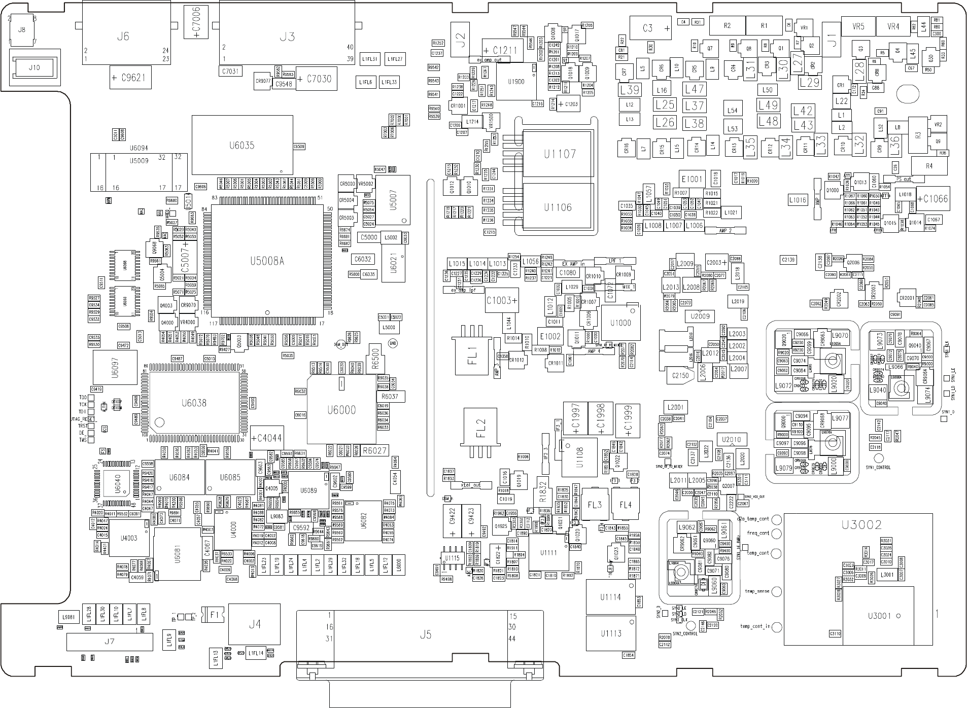
MM-E 2072-09333-00
COMPONENT SIDE
Figure B-3.A. LORD Module, Identification of Components (Sheet 1 of 2)
B-55/B-56
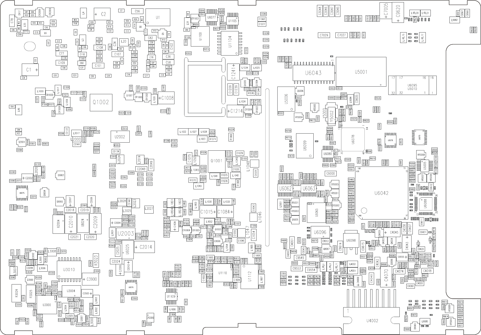
MM-E 2072-09333-00
PRINT
SIDE
Figure B-3.B. LORD Module, Identification of Components (Sheet 2 of 2)
B-57/B-58

MM-E 2072-09333-00
B-59
Table B-4. HI POWER Module, Parts List
Ref. Des. Mfg. Catalog No.
Description Qty.
2072-95170-10 HI POWER MODULE Figure B-4
BL1 2072-45014-00 POWER PAD 1.0
BL2 2072-32170-00 HI POWER PCB 1.0
BL3 4052-15003-00 SCREW, CROSS RECESSED, PAN HEAD 8.0
BL4 2072-33051-00 SPACER 1.0
BL5 2072-53004-00 WASHER, SHLDR 1483967A03 1.0
BL6 2072-40050-00 SHIELD, 2683423K03 1.0
BL7 2072-48026-00 SHIELD, RF 1.0
BL8 4052-12014-16 SCREW, M2X16, PAN HEAD 10.0
BL9 4053-70003-16 WASHER, SPRING, M2 10.0
BL10 4068-00007-20 WIRE, EL UNINSULATED, AWG, 20 .10
BL11 4053-16001-00 WASHER, SPRING, LOCK, M3 4.0
BL12 2201-63202-03 HEATSINK COMPOUND, DC340 .200
BL14 2201-64113-19 RTV734, CLEAR .10
BL15 2072-90210-10 CABLE ANTENNA 1.0
BL16 2201-64106-05 ELECOLIT 631, A+B .50
BL17 2338-56025-00 ADHESIVE BACK MOUNTS 1.0
BL18 2388-56043-00 STRIP, SST, 1.5M 1.0
BL19 2072-72024-00 IDENTIFICATION LABEL FOR 207295170F 1.0
C1 4017-20109-00 CAPACITOR, 1206, X7R, 10UF 1.0
C2 4017-20153-00 CAPACITOR, CHIP, CERAMIC, 2.2UF, 25V 1.0
C3 4017-80116-02 CAPACITOR, CHIP, TANTALUM, 4.7UF, 20V 1.0
C4 4017-80115-20 CAPACITOR, CHIP, TANTALUM, 47U 1.0
C5 4017-20271-00 CAPACITOR, CHIP, X7R, 10NF, 10% 1.0
C6 4017-20271-00 CAPACITOR, CHIP, X7R, 10NF, 10% 1.0
C8 4017-25282-00 CAPACITOR, CHIP, CG, 1NF, 5% 1.0
C9 4017-25282-00 CAPACITOR, CHIP, CG, 1NF, 5% 1.0
C10 4017-25282-00 CAPACITOR, CHIP, CG, 1NF, 5% 1.0
C11 4017-25282-00 CAPACITOR, CHIP, CG, 1NF, 5% 1.0
C12 4017-20284-00 CAPACITOR, CHIP, CERAMIC, 100NF, 16V 1.0
C13 4017-20271-00 CAPACITOR, CHIP, X7R, 10NF, 10% 1.0
C14 4017-20165-00 CAPACITOR, CHIP, CERAMIC, 100NF, 50V 1.0
C15 4017-80226-00 CAPACITOR, CHIP, TANTALUM, 15UF, 35V 1.0
C16 4017-20153-00 CAPACITOR, CHIP, CERAMIC, 2.2UF, 25V 1.0
C17 4017-20284-00 CAPACITOR, CHIP, CERAMIC, 100NF, 16V 1.0
C18 4017-20284-00 CAPACITOR, CHIP, CERAMIC, 100NF, 16V 1.0
C19 4017-20271-00 CAPACITOR, CHIP, X7R, 10NF, 10% 1.0
C20 4017-20271-00 CAPACITOR, CHIP, X7R, 10NF, 10% 1.0
C21 4017-20181-00 CAPACITOR, 1210, X7R, 100NF, 200V 1.0
C22 4017-20102-00 CAPACITOR, CHIP, 10NF, 200V 1.0

MM-E 2072-09333-00
B-60
Table B-4. HI POWER Module, Parts List (Cont’d)
Ref. Des. Mfg. Catalog No.
Description Qty.
C23 4017-20181-00 CAPACITOR, 1210, X7R, 100NF, 200V 1.0
C24 2089-17033-00 CAPACITOR, PORCELAN, 470PF, 5% 1.0
C26 4017-20165-00 CAPACITOR, CHIP, CERAMIC, 100NF, 50V 1.0
C27 4017-20165-00 CAPACITOR, CHIP, CERAMIC, 100NF, 50V 1.0
C28 2089-17033-00 CAPACITOR, PORCELAN, 470PF, 5% 1.0
C29 2089-17033-00 CAPACITOR, PORCELAN, 470PF, 5% 1.0
C30 4017-25101-00 CAPACITOR, CHIP, CERAMIC, 1NF, 200V 1.0
C32 4017-80115-20 CAPACITOR, CHIP, TANTALUM, 47U 1.0
C34 4017-20165-00 CAPACITOR, CHIP, CERAMIC, 100NF, 50V 1.0
C36 4017-20181-00 CAPACITOR, 1210, X7R, 100NF, 200V 1.0
C37 4017-25101-00 CAPACITOR, CHIP, CERAMIC, 1NF, 200V 1.0
C38 4017-20102-00 CAPACITOR, CHIP, 10NF, 200V 1.0
C40 2089-17033-00 CAPACITOR, PORCELAN, 470PF, 5% 1.0
C41 4017-20181-00 CAPACITOR, 1210, X7R, 100NF, 200V 1.0
C43 4017-20165-00 CAPACITOR, CHIP, CERAMIC, 100NF, 50V 1.0
C44 4017-20165-00 CAPACITOR, CHIP, CERAMIC, 100NF, 50V 1.0
C45 4017-20165-00 CAPACITOR, CHIP, CERAMIC, 100NF, 50V 1.0
C46 4017-20165-00 CAPACITOR, CHIP, CERAMIC, 100NF, 50V 1.0
C47 4017-25093-00 CAPACITOR, CHIP, CERAMIC, C0G, 10NF 1.0
C48 4017-20165-00 CAPACITOR, CHIP, CERAMIC, 100NF, 50V 1.0
C49 4017-20165-00 CAPACITOR, CHIP, CERAMIC, 100NF, 50V 1.0
C50 4017-20271-00 CAPACITOR, CHIP, X7R, 10NF, 10% 1.0
C51 4017-25093-00 CAPACITOR, CHIP, CERAMIC, C0G, 10NF 1.0
C52 4017-20165-00 CAPACITOR, CHIP, CERAMIC, 100NF, 50V 1.0
C53 4017-20165-00 CAPACITOR, CHIP, CERAMIC, 100NF, 50V 1.0
C55 4017-20109-00 CAPACITOR, 1206, X7R, 10UF 1.0
C56 4017-20165-00 CAPACITOR, CHIP, CERAMIC, 100NF, 50V 1.0
C57 4017-20284-00 CAPACITOR, CHIP, CERAMIC, 100NF, 16V 1.0
C58 4017-20153-00 CAPACITOR, CHIP, CERAMIC, 2.2UF, 25V 1.0
C59 4017-20165-00 CAPACITOR, CHIP, CERAMIC, 100NF, 50V 1.0
C60 4017-20165-00 CAPACITOR, CHIP, CERAMIC, 100NF, 50V 1.0
C62 4017-80116-02 CAPACITOR, CHIP, TANTALUM, 4.7UF, 20V 1.0
C63 4017-25265-10 CAPACITOR, CHIP, NP0, 33PF, 1% 1.0
C65 2089-17003-00 CAPACITOR, PORCELAN, 10PF, 5% 1.0
C66 2089-17003-00 CAPACITOR, PORCELAN, 10PF, 5% 1.0
C67 4017-20284-00 CAPACITOR, CHIP, CERAMIC, 100NF, 16V 1.0
C70 4017-25274-00 CAPACITOR, 0603, NP0, 180PF, 50V 1.0
C71 4017-25274-00 CAPACITOR, 0603, NP0, 180PF, 50V 1.0
C72 2089-17003-00 CAPACITOR, PORCELAN, 10PF, 5% 1.0
C73 4017-80105-02 CAPACITOR, CHIP, TANTALUM, 22UF, 25V 1.0

MM-E 2072-09333-00
B-61
Table B-4. HI POWER Module, Parts List (Cont’d)
Ref. Des. Mfg. Catalog No.
Description Qty.
C74 2089-17003-00 CAPACITOR, PORCELAN, 10PF, 5% 1.0
C75 2089-17003-00 CAPACITOR, PORCELAN, 10PF, 5% 1.0
C76 4017-20165-00 CAPACITOR, CHIP, CERAMIC, 100NF, 50V 1.0
C77 2089-17003-00 CAPACITOR, PORCELAN, 10PF, 5% 1.0
C78 4017-25274-00 CAPACITOR, 0603, NP0, 180PF, 50V 1.0
C79 4017-20165-00 CAPACITOR, CHIP, CERAMIC, 100NF, 50V 1.0
C80 4017-20165-00 CAPACITOR, CHIP, CERAMIC, 100NF, 50V 1.0
C82 4017-25274-00 CAPACITOR, 0603, NP0, 180PF, 50V 1.0
C83 4017-25267-00 CAPACITOR, CHIP, 0603, NP0, 47PF 1.0
C84 4017-25267-00 CAPACITOR, CHIP, 0603, NP0, 47PF 1.0
C86 4017-20284-00 CAPACITOR, CHIP, CERAMIC, 100NF, 16V 1.0
C87 4017-25282-00 CAPACITOR, CHIP, CG, 1NF, 5% 1.0
C88 4017-25282-00 CAPACITOR, CHIP, CG, 1NF, 5% 1.0
C89 4017-20165-00 CAPACITOR, CHIP, CERAMIC, 100NF, 50V 1.0
C90 4017-20153-00 CAPACITOR, CHIP, CERAMIC, 2.2UF, 25V 1.0
C91 4017-20165-00 CAPACITOR, CHIP, CERAMIC, 100NF, 50V 1.0
C93 4017-20109-00 CAPACITOR, 1206, X7R, 10UF, 1.0
C94 4017-25279-00 CAPACITOR, CHIP, CG, 470PF, 5% 1.0
C95 4017-80116-02 CAPACITOR, CHIP, TANTALUM, 4.7UF, 20V 1.0
C96 4017-20271-00 CAPACITOR, CHIP, X7R, 10NF, 10% 1.0
C97 4017-25279-00 CAPACITOR, CHIP, CG, 470PF, 5% 1.0
C98 4017-20284-00 CAPACITOR, CHIP, CERAMIC, 100NF, 16V 1.0
C99 4017-20271-00 CAPACITOR, CHIP, X7R, 10NF, 10% 1.0
C100 4017-20192-00 CAPACITOR, 1210, X7R, 4.7UF, 50V 1.0
C101 2089-17022-00 CAPACITOR, PORCELAN, 150PF, 5% 1.0
C102 2089-17033-00 CAPACITOR, PORCELAN, 470PF, 5% 1.0
C103 2089-17026-00 CAPACITOR, PORCELAN, 240PF, 5% 1.0
C105 2089-17033-00 CAPACITOR, PORCELAN, 470PF, 5% 1.0
C106 2089-17033-00 CAPACITOR, PORCELAN, 470PF, 5% 1.0
C107 2089-17033-00 CAPACITOR, PORCELAN, 470PF, 5% 1.0
C108 2089-17033-00 CAPACITOR, PORCELAN, 470PF, 5% 1.0
C109 2089-17033-00 CAPACITOR, PORCELAN, 470PF, 5% 1.0
C110 2089-17033-00 CAPACITOR, PORCELAN, 470PF, 5% 1.0
C111 2089-17033-00 CAPACITOR, PORCELAN, 470PF, 5% 1.0
C112 2089-17033-00 CAPACITOR, PORCELAN, 470PF, 5% 1.0
C113 2089-17033-00 CAPACITOR, PORCELAN, 470PF, 5% 1.0
C114 2089-17033-00 CAPACITOR, PORCELAN, 470PF, 5% 1.0
C115 2089-17023-00 CAPACITOR, PORCELAN, 180PF, 5% 1.0
C116 4017-20284-00 CAPACITOR, CHIP, CERAMIC, 100NF, 16V 1.0
C118 4017-25279-00 CAPACITOR, CHIP, CG, 470PF, 5% 1.0

MM-E 2072-09333-00
B-62
Table B-4. HI POWER Module, Parts List (Cont’d)
Ref. Des. Mfg. Catalog No.
Description Qty.
C121 4017-80234-00 CAPACITOR, CHIP, TANTALUM, 100UF, 20V 1.0
C122 4017-20165-00 CAPACITOR, CHIP, CERAMIC, 100NF, 50V 1.0
C123 4017-20109-00 CAPACITOR, 1206, X7R, 10UF 1.0
C124 4017-20109-00 CAPACITOR, 1206, X7R, 10UF 1.0
C126 4017-25279-00 CAPACITOR, CHIP, CG, 470PF, 5% 1.0
C128 4017-80226-00 CAPACITOR, CHIP, TANTALUM, 15UF, 35V 1.0
C129 4017-80105-02 CAPACITOR, CHIP, TANTALUM, 22UF, 25V 1.0
C130 4017-20284-00 CAPACITOR, CHIP, CERAMIC, 100NF, 16V 1.0
C131 4017-80115-20 CAPACITOR, CHIP, TANTALUM, 47U 1.0
C132 4017-20284-00 CAPACITOR, CHIP, CERAMIC, 100NF, 16V 1.0
C134 4017-80226-00 CAPACITOR, CHIP, TANTALUM, 15UF, 35V 1.0
C135 4017-20192-00 CAPACITOR, 1210, X7R, 4.7UF, 50V 1.0
C136 4017-20271-00 CAPACITOR, CHIP, X7R, 10NF, 10% 1.0
C137 4017-20271-00 CAPACITOR, CHIP, X7R, 10NF, 10% 1.0
C138 4017-80226-00 CAPACITOR, CHIP, TANTALUM, 15UF, 35V 1.0
C139 4017-20192-00 CAPACITOR, 1210, X7R, 4.7UF, 50V 1.0
C140 4017-20192-00 CAPACITOR, 1210, X7R, 4.7UF, 50V 1.0
C141 4017-20271-00 CAPACITOR, CHIP, X7R, 10NF, 10% 1.0
C142 4017-20271-00 CAPACITOR, CHIP, X7R, 10NF, 10% 1.0
C143 4017-20165-00 CAPACITOR, CHIP, CERAMIC, 100NF, 50V 1.0
C145 4017-20109-00 CAPACITOR, 1206, X7R, 10UF 1.0
C146 4017-20109-00 CAPACITOR, 1206, X7R, 10UF 1.0
C147 4017-20109-00 CAPACITOR, 1206, X7R, 10UF 1.0
C148 4017-20284-00 CAPACITOR, CHIP, CERAMIC, 100NF, 16V 1.0
C149 4017-20284-00 CAPACITOR, CHIP, CERAMIC, 100NF, 16V 1.0
C150, 4017-20284-00 CAPACITOR, CHIP, CERAMIC, 100NF, 16V 1.0
C151 4017-20284-00 CAPACITOR, CHIP, CERAMIC, 100NF, 16V 1.0
C152 4017-20284-00 CAPACITOR, CHIP, CERAMIC, 100NF, 16V 1.0
C153 4017-20192-00 CAPACITOR, 1210, X7R, 4.7UF, 50V 1.0
C154 4017-20192-00 CAPACITOR, 1210, X7R, 4.7UF, 50V 1.0
C155 4017-25282-00 CAPACITOR, CHIP, CG, 1NF, 5% 1.0
C156 4017-25279-00 CAPACITOR, CHIP, CG, 470PF, 5% 1.0
C157 4017-20284-00 CAPACITOR, CHIP, CERAMIC, 100NF, 16V 1.0
C158 4017-20192-00 CAPACITOR, 1210, X7R, 4.7UF, 50V 1.0
C160 4017-80234-00 CAPACITOR, CHIP, TANTALUM, 100UF, 20V 1.0
C161 4017-20165-00 CAPACITOR, CHIP, CERAMIC, 100NF, 50V 1.0
C162 4017-20165-00 CAPACITOR, CHIP, CERAMIC, 100NF, 50V 1.0
C163 4017-20165-00 CAPACITOR, CHIP, CERAMIC, 100NF, 50V 1.0
C164 4017-20165-00 CAPACITOR, CHIP, CERAMIC, 100NF, 50V 1.0
C165 4017-20165-00 CAPACITOR, CHIP, CERAMIC, 100NF, 50V 1.0

MM-E 2072-09333-00
B-63
Table B-4. HI POWER Module, Parts List (Cont’d)
Ref. Des. Mfg. Catalog No.
Description Qty.
C166 4017-25282-00 CAPACITOR, CHIP, CG, 1NF, 5% 1.0
C167 4017-20165-00 CAPACITOR, CHIP, CERAMIC, 100NF, 50V 1.0
C168 4017-25282-00 CAPACITOR, CHIP, CG, 1NF, 5% 1.0
C169 4017-20165-00 CAPACITOR, CHIP, CERAMIC, 100NF, 50V 1.0
C171 4017-20153-00 CAPACITOR, CHIP, CERAMIC, 2.2UF, 25V 1.0
C173 4017-25271-00 CAPACITOR, CHIP, CG, 100PF, 5% 1.0
C174 4017-20109-00 CAPACITOR, 1206, X7R, 10UF 1.0
C201 2089-17022-00 CAPACITOR, PORCELAN, 150PF, 5% 1.0
C202 2089-17033-00 CAPACITOR, PORCELAN, 470PF, 5% 1.0
C203 2089-17023-00 CAPACITOR, PORCELAN, 180PF, 5% 1.0
C204 2089-17029-00 CAPACITOR, PORCELAN, 330PF, 5% 1.0
C205 2089-17029-00 CAPACITOR, PORCELAN, 330PF, 5% 1.0
C206 2089-17027-00 CAPACITOR, PORCELAN, 270PF, 5% 1.0
C207 2089-17033-00 CAPACITOR, PORCELAN, 470PF, 5% 1.0
C208 2089-17033-00 CAPACITOR, PORCELAN, 470PF, 5% 1.0
C209 2089-17015-00 CAPACITOR, PORCELAN, 68PF, 5% 1.0
C211 2089-17029-00 CAPACITOR, PORCELAN, 330PF, 5% 1.0
C212 2089-17033-00 CAPACITOR, PORCELAN, 470PF, 5% 1.0
C301 2089-17029-00 CAPACITOR, PORCELAN, 330PF, 5% 1.0
C302 2089-17033-00 CAPACITOR, PORCELAN, 470PF, 5% 1.0
C303 2089-17019-00 CAPACITOR, PORCELAN, 100PF, 5% 1.0
C304 2089-17033-00 CAPACITOR, PORCELAN, 470PF, 5% 1.0
C305 2089-17029-00 CAPACITOR, PORCELAN, 330PF, 5% 1.0
C306 2089-17033-00 CAPACITOR, PORCELAN, 470PF, 5% 1.0
C401 2089-17025-00 CAPACITOR, PORCELAN, 220PF, 5% 1.0
C402 2089-17031-00 CAPACITOR, PORCELAN, 390PF, 5% 1.0
C403 2089-17017-00 CAPACITOR, PORCELAN, 82PF, 5% 1.0
C404 2089-17025-00 CAPACITOR, PORCELAN, 220PF, 5% 1.0
C405 2089-17024-00 CAPACITOR, PORCELAN, 200PF, 5% 1.0
C406 2089-17024-00 CAPACITOR, PORCELAN, 200PF, 5% 1.0
C407 2089-17019-00 CAPACITOR, PORCELAN, 100PF, 5% 1.0
C501 2089-17023-00 CAPACITOR, PORCELAN, 180PF, 5% 1.0
C502 2089-17013-00 CAPACITOR, PORCELAN, 56PF, 5% 1.0
C503 2089-17022-00 CAPACITOR, PORCELAN, 150PF, 5% 1.0
C504 2089-17019-00 CAPACITOR, PORCELAN, 100PF, 5% 1.0
C505 2089-17023-00 CAPACITOR, PORCELAN, 180PF, 5% 1.0
C506 2089-17023-00 CAPACITOR, PORCELAN, 180PF, 5% 1.0
C601 2089-17017-00 CAPACITOR, PORCELAN, 82PF, 5% 1.0
C602 2089-17007-00 CAPACITOR, PORCELAN, 22PF, 5% 1.0
C603 2089-17009-00 CAPACITOR, PORCELAN, 30PF, 5% 1.0

MM-E 2072-09333-00
B-64
Table B-4. HI POWER Module, Parts List (Cont’d)
Ref. Des. Mfg. Catalog No.
Description Qty.
C604 2089-17022-00 CAPACITOR, PORCELAN, 150PF, 5% 1.0
C605 2089-17013-00 CAPACITOR, PORCELAN, 56PF, 5% 1.0
C606 2089-17027-00 CAPACITOR, PORCELAN, 270PF, 5% 1.0
C701 2089-17013-00 CAPACITOR, PORCELAN, 56PF, 5% 1.0
C702 2089-17019-00 CAPACITOR, PORCELAN, 100PF, 5% 1.0
C703 4017-60012-20 CAPACITOR, PORC. 18PF, 2% 1.0
C704 2089-17017-00 CAPACITOR, PORCELAN, 82PF, 5% 1.0
C706 2089-17017-00 CAPACITOR, PORCELAN, 82PF, 5% 1.0
C707 4017-20181-00 CAPACITOR, 1210, X7R, 100NF, 200V 1.0
C708 4017-20102-00 CAPACITOR, CHIP, 10NF, 200V 1.0
C846 4017-80115-02 CAPACITOR, CHIP, 47UF, 10V 1.0
C848 4017-20271-00 CAPACITOR, CHIP, X7R, 10NF, 10% 1.0
C850 4017-20271-00 CAPACITOR, CHIP, X7R, 10NF, 10% 1.0
C851 4017-20271-00 CAPACITOR, CHIP, X7R, 10NF, 10% 1.0
C852 4017-20165-00 CAPACITOR, CHIP, CERAMIC, 100NF, 50V 1.0
C853 2089-17033-00 CAPACITOR, PORCELAN, 470PF, 5% 1.0
C854 4017-80115-02 CAPACITOR, CHIP, 47UF, 10V 1.0
C855 4017-25282-00 CAPACITOR, CHIP, CG, 1NF, 5% 1.0
C856 4017-20284-00 CAPACITOR, CHIP, CERAMIC, 100NF, 16V 1.0
C858 4017-25282-00 CAPACITOR, CHIP, CG, 1NF, 5% 1.0
C860 2089-17013-00 CAPACITOR, PORCELAN, 56PF, 5% 1.0
C861 2089-17029-00 CAPACITOR, PORCELAN, 330PF, 5% 1.0
C862 2089-17029-00 CAPACITOR, PORCELAN, 330PF, 5% 1.0
C863 2089-17033-00 CAPACITOR, PORCELAN, 470PF, 5% 1.0
C864 2089-17033-00 CAPACITOR, PORCELAN, 470PF, 5% 1.0
C865 2089-17029-00 CAPACITOR, PORCELAN, 330PF, 5% 1.0
C866 4017-25282-00 CAPACITOR, CHIP, CG, 1NF, 5% 1.0
C867 4017-25282-00 CAPACITOR, CHIP, CG, 1NF, 5% 1.0
C868 4017-25282-00 CAPACITOR, CHIP, CG, 1NF, 5% 1.0
C869 4017-20181-00 CAPACITOR, 1210, X7R, 100NF, 200V 1.0
C870 4017-25282-00 CAPACITOR, CHIP, CG, 1NF, 5% 1.0
C871 4017-20181-00 CAPACITOR, 1210, X7R, 100NF, 200V 1.0
C872 4017-25282-00 CAPACITOR, CHIP, CG, 1NF, 5% 1.0
C873 4017-80226-00 CAPACITOR, CHIP, TANTALUM, 15UF, 35V 1.0
C875 4017-20284-00 CAPACITOR, CHIP, CERAMIC, 100NF, 16V 1.0
C877 4017-20165-00 CAPACITOR, CHIP, CERAMIC, 100NF, 50V 1.0
C878 4017-80226-00 CAPACITOR, CHIP, TANTALUM, 15UF, 35V 1.0
C880 4017-20192-00 CAPACITOR, 1210, X7R, 4.7UF, 50V 1.0
C882 4017-20165-00 CAPACITOR, CHIP, CERAMIC, 100NF, 50V 1.0
C884 4017-20284-00 CAPACITOR, CHIP, CERAMIC, 100NF, 16V 1.0

MM-E 2072-09333-00
B-65
Table B-4. HI POWER Module, Parts List (Cont’d)
Ref. Des. Mfg. Catalog No.
Description Qty.
C885 4017-20284-00 CAPACITOR, CHIP, CERAMIC, 100NF, 16V 1.0
C886 4017-25282-00 CAPACITOR, CHIP, CG, 1NF, 5% 1.0
C887 4017-20284-00 CAPACITOR, CHIP, CERAMIC, 100NF, 16V 1.0
C888 4017-20284-00 CAPACITOR, CHIP, CERAMIC, 100NF, 16V 1.0
C889 4017-20284-00 CAPACITOR, CHIP, CERAMIC, 100NF, 16V 1.0
C895 4017-20271-00 CAPACITOR, CHIP, X7R, 10NF, 10% 1.0
C896 4017-20284-00 CAPACITOR, CHIP, CERAMIC, 100NF, 16V 1.0
C897 4017-20284-00 CAPACITOR, CHIP, CERAMIC, 100NF, 16V 1.0
C898 4017-20271-00 CAPACITOR, CHIP, X7R, 10NF, 10% 1.0
C900 4017-20284-00 CAPACITOR, CHIP, CERAMIC, 100NF, 16V 1.0
C901 4017-20271-00 CAPACITOR, CHIP, X7R, 10NF, 10% 1.0
C902 4017-25271-00 CAPACITOR, CHIP, CG, 100PF, 5% 1.0
C903 4017-25259-00 CAPACITOR, CHIP, CG, 10PF, 5% 1.0
C904 4017-20284-00 CAPACITOR, CHIP, CERAMIC, 100NF, 16V 1.0
C905 4017-20284-00 CAPACITOR, CHIP, CERAMIC, 100NF, 16V 1.0
C906 4017-25282-00 CAPACITOR, CHIP, CG, 1NF, 5% 1.0
CR1 4021-10721-35 DIODE 1.0
CR6 4021-10114-35 DIODE, SCHOTTKY, HSMS2800 1.0
CR7 4021-10114-35 DIODE, SCHOTTKY, HSMS2800 1.0
CR8 2072-21018-00 DIODE, PIN 1.0
CR9 2072-21018-00 DIODE, PIN 1.0
CR10 4021-10721-35 DIODE 1.0
CR11 4021-10721-35 DIODE 1.0
CR13 4021-10403-35 DIODE, RECTIFIER, SCHOTTKY, MBRS360 1.0
CR14 4021-10282-35 DIODE, RECTIFIER 1.0
CR15 4021-10745-35 DIODE, SCHOTTKY 1.0
CR16 4021-10745-35 DIODE, SCHOTTKY 1.0
CR17 4021-10745-35 DIODE, SCHOTTKY 1.0
CR18 4021-10745-35 DIODE, SCHOTTKY 1.0
CR19 4021-10745-35 DIODE, SCHOTTKY 1.0
CR20 4021-10745-35 DIODE, SCHOTTKY 1.0
CR805 4021-10722-35 DIODE, DUAL 1.0
CR806 4021-10721-35 DIODE 1.0
CR809 4021-10513-35 DIODE, SCHOTTKY 1.0
CR810 4021-10114-35 DIODE, SCHOTTKY, HSMS2800 1.0
CR811 4021-10513-35 DIODE, SCHOTTKY 1.0
E1 4033-10178-01 SCREW TERMINAL, PC MOUNT 1.0
E2 4033-10178-01 SCREW TERMINAL, PC MOUNT 1.0
E3 4018-60032-00 BEAD, EMI, 600 OHM, 1.5A 1.0
E6 4018-60032-00 BEAD, EMI, 600 OHM, 1.5A 1.0

MM-E 2072-09333-00
B-66
Table B-4. HI POWER Module, Parts List (Cont’d)
Ref. Des. Mfg. Catalog No.
Description Qty.
E19 4023-00014-00 ARRESTOR 1.0
E26 4018-60032-00 BEAD, EMI, 600 OHM, 1.5A 1.0
E27 4018-60032-00 BEAD, EMI, 600 OHM, 1.5A 1.0
E28 4018-60032-00 BEAD, EMI, 600 OHM, 1.5A 1.0
E29 4018-60032-00 BEAD, EMI, 600 OHM, 1.5A 1.0
K1 2338-31031-00 RELAY, 5V, DPDT 1.0
K101 2338-31031-00 RELAY, 5V, DPDT 1.0
K102 2338-31031-00 RELAY, 5V, DPDT 1.0
K201 2338-31031-00 RELAY, 5V, DPDT 1.0
K202 2338-31031-00 RELAY, 5V, DPDT 1.0
K301 2338-31031-00 RELAY, 5V, DPDT 1.0
K302 2338-31031-00 RELAY, 5V, DPDT 1.0
K401 2338-31031-00 RELAY, 5V, DPDT 1.0
K402 2338-31031-00 RELAY, 5V, DPDT 1.0
K501 2338-31031-00 RELAY, 5V, DPDT 1.0
K502 2338-31031-00 RELAY, 5V, DPDT 1.0
K601 2338-31031-00 RELAY, 5V, DPDT 1.0
K602 2338-31031-00 RELAY, 5V, DPDT 1.0
K701 2338-31031-00 RELAY, 5V, DPDT 1.0
K702 2338-31031-00 RELAY, 5V, DPDT 1.0
L1 4018-10117-00 INDUCTOR, 10UH 1.0
L2 4018-01022-00 COIL, 56UH, 10% 1.0
L3 4018-10117-00 INDUCTOR, 10UH 1.0
L11 4018-16024-00 COIL, CHIP, AIR, 68NH 1.0
L14 4018-10116-00 INDUCTOR, 33UH 1.0
L17 4018-16024-00 COIL, CHIP, AIR, 68NH 1.0
L18 4018-10116-00 INDUCTOR, 33UH 1.0
L19 4018-01022-00 COIL, 56UH, 10% 1.0
L20 4018-10116-00 INDUCTOR, 33UH 1.0
L101 2072-13023-13 COIL, RF, 3.39uH 1.0
L102 2072-13023-14 COIL, RF, 5.20uH 1.0
L201 2072-13023-11 COIL, RF, 2.20uH 1.0
L202 2072-13023-12 COIL, RF, 2.60uH 1.0
L301 2072-13023-09 COIL, RF, 1.35uH 1.0
L302 2072-13023-10 COIL, RF, 1.90uH 1.0
L401 2072-13023-07 COIL, RF, 0.88uH 1.0
L402 2072-13023-08 COIL, RF, 1.12uH 1.0
L501 2072-13023-05 COIL, RF, 0.55uH 1.0
L502 2072-13023-06 COIL, RF, 0.71uH 1.0
L601 2072-13023-03 COIL, RF, 0.55uH 1.0

MM-E 2072-09333-00
B-67
Table B-4. HI POWER Module, Parts List (Cont’d)
Ref. Des. Mfg. Catalog No.
Description Qty.
L602 2072-13023-05 COIL, RF, 0.55uH 1.0
L701 2072-13023-01 COIL, RF, 0.28uH 1.0
L702 2072-13023-01 COIL, RF, 0.28uH 1.0
P2 2072-33016-00 RECEPTACLE, COAX 1.0
P3 2072-33007-00 HEADER, RT, 40 PIN 1.0
P4 2072-33016-00 RECEPTACLE, COAX 1.0
Q1 4021-00302-35 TRANSISTOR, N-CHANNEL, DUAL 1.0
Q2 4021-00202-35 TRANSISTOR, NPN, MMBT2222A 1.0
Q3 4021-06065-35 FET, RF 1.0
Q4 4021-06065-35 FET, RF 1.0
Q5 4021-06061-35 FET, RF 1.0
Q6 2072-21086-00 TRANSISTOR, POWER 1.0
Q7 4021-06061-35 FET, RF 1.0
Q8 4021-07057-35 TRANSISTOR, N-CHANNEL 1.0
Q10 4021-00341-35 TRANSISTOR, PNP 1.0
Q11 2072-21086-00 TRANSISTOR, POWER 1.0
Q12 4021-00415-35 FET, RF 1.0
Q13 4021-00302-35 TRANSISTOR, N-CHANNEL, DUAL 1.0
Q14 4021-07181-35 TRANSISTOR, N-CHANNEL 1.0
Q15 4021-07085-35 TRANSISTOR, P-CHANNEL 1.0
Q16 4021-00202-35 TRANSISTOR, NPN, MMBT2222A 1.0
Q17 4021-00415-35 FET 1.0
Q19 4021-00415-35 FET 1.0
Q20 4021-00341-35 TRANSISTOR, PNP 1.0
Q22 4021-00202-35 TRANSISTOR, NPN, MMBT2222A 1.0
Q23 4021-00202-35 TRANSISTOR, NPN, MMBT2222A 1.0
Q26 4021-07181-35 TRANSISTOR, N-CHANNEL 1.0
Q801 4021-00415-35 FET 1.0
Q802 4021-00341-35 TRANSISTOR, PNP 1.0
Q803 4021-00202-35 TRANSISTOR, NPN, MMBT2222A 1.0
Q805 4021-00415-35 FET 1.0
Q806 4021-00202-35 TRANSISTOR, NPN, MMBT2222A 1.0
Q807 4021-00202-35 TRANSISTOR, NPN, MMBT2222A 1.0
R1 4016-21000-10 RESISTOR, 100, 1%, 1/16W 1.0
R2 4016-21000-10 RESISTOR, 100, 1%, 1/16W 1.0
R4 4016-23321-10 RESISTOR, 3.32K, 1%, 1/16W 1.0
R5 4016-22439-10 RESISTOR, 24.3, 1%, 1/16W 1.0
R6 4016-21008-50 RESISTOR, CHIP, 0603, 1 OHM, 5% 1.0
R7 4016-21008-50 RESISTOR, CHIP, 0603, 1 OHM, 5% 1.0
R8 4016-21008-50 RESISTOR, CHIP, 0603, 1 OHM, 5% 1.0

MM-E 2072-09333-00
B-68
Table B-4. HI POWER Module, Parts List (Cont’d)
Ref. Des. Mfg. Catalog No.
Description Qty.
R9 4016-21008-50 RESISTOR, CHIP, 0603, 1 OHM, 5% 1.0
R11 4016-21000-10 RESISTOR, 100, 1%, 1/16W 1.0
R13 4016-21503-10 RESISTOR, 150K, 1%, 1/16W 1.0
R15 4016-20000-50 RESISTOR, CHIP, 0603, JUMPER 1.0
R18 4016-21002-10 RESISTOR, 10.0K, 1%, 1/16W 1.0
R20 4016-23162-10 RESISTOR, CHIP, 0603, 31.6K, 1% 1.0
R21 4016-43329-10 RESISTOR, CHIP, 33.2, 1%, 1W 1.0
R22 4016-60102-00 TRIMPOT, 10K OHM 1.0
R23 4016-25119-10 RESISTOR, CHIP, 0603, 51.1, 1% 1.0
R24 4016-43329-10 RESISTOR, CHIP, 33.2, 1%, 1W 1.0
R25 4016-25119-10 RESISTOR, CHIP, 0603, 51.1, 1% 1.0
R26 4016-43329-10 RESISTOR, CHIP, 33.2, 1%, 1W 1.0
R27 4016-43329-10 RESISTOR, CHIP, 33.2, 1%, 1W 1.0
R28 4016-40479-50 RESISTOR, CHIP, 4.7, 5%, 1W 1.0
R29 4016-14120-10 RESISTOR, CHIP, 412, 1%, 1/8W 1.0
R30 4016-14120-10 RESISTOR, CHIP, 412, 1%, 1/8W 1.0
R31 4016-40479-50 RESISTOR, CHIP, 4.7, 5%, 1W 1.0
R32 4016-14120-10 RESISTOR, CHIP, 412, 1%, 1/8W 1.0
R33 4016-14120-10 RESISTOR, CHIP, 412, 1%, 1/8W 1.0
R34 4016-11002-10 RESISTOR, CHIP, 10.0K, 1%, 1/8W 1.0
R35 4016-11002-10 RESISTOR, CHIP, 10.0K, 1%, 1/8W 1.0
R36 4016-60000-50 RESISTOR, CHIP, 0 OHM, 1/2W 1.0
R39 4016-32900-10 RESISTOR, CHIP, 0.2, 1%, 1W 1.0
R40 4016-43329-10 RESISTOR, CHIP, 33.2, 1%, 1W 1.0
R41 4016-43329-10 RESISTOR, CHIP, 33.2, 1%, 1W 1.0
R43 4016-43329-10 RESISTOR, CHIP, 33.2, 1%, 1W 1.0
R44 4016-43329-10 RESISTOR, CHIP, 33.2, 1%, 1W 1.0
R46 4016-21001-10 RESISTOR, 1.00K, 1%, 1/16W 1.0
R47 4016-21002-10 RESISTOR, 10.0K, 1%, 1/16W 1.0
R48 4016-21002-10 RESISTOR, 10.0K, 1%, 1/16W 1.0
R49 4016-25112-10 RESISTOR, 51.1K, 1%, 1/16W 1.0
R50 4016-24750-10 RESISTOR, 475, 1%, 1/16W 1.0
R51 4016-24753-10 RESISTOR, CHIP, 0603, 475K, 1% 1.0
R53 4016-21000-10 RESISTOR, 100, 1%, 1/16W 1.0
R55 4016-24750-10 RESISTOR, 475, 1%, 1/16W 1.0
R57 4016-21829-10 RESISTOR, CHIP, 0603, 18.2, 1% 1.0
R58 4016-23321-10 RESISTOR, 3.32K, 1%, 1/16W 1.0
R59 4016-21001-10 RESISTOR, 1.00K, 1%, 1/16W 1.0
R60 4016-20000-50 RESISTOR, CHIP, 0603, JUMPER 1.0
R61 4016-23652-10 RESISTOR, 36.5K, 1%, 1/16W 1.0

MM-E 2072-09333-00
B-69
Table B-4. HI POWER Module, Parts List (Cont’d)
Ref. Des. Mfg. Catalog No.
Description Qty.
R62 4016-23010-10 RESISTOR, CHIP, 0603, 301, 1% 1.0
R63 4016-23010-10 RESISTOR, CHIP, 0603, 301, 1% 1.0
R64 4016-21001-10 RESISTOR, 1.00K, 1%, 1/16W 1.0
R65 4016-21002-10 RESISTOR, 10.0K, 1%, 1/16W 1.0
R66 4016-21002-10 RESISTOR, 10.0K, 1%, 1/16W 1.0
R67 4016-60102-00 TRIMPOT, 10K OHM 1.0
R68 4016-20000-50 RESISTOR, CHIP, 0603, JUMPER 1.0
R69 4016-21001-10 RESISTOR, 1.00K, 1%, 1/16W 1.0
R70 4016-21002-10 RESISTOR, 10.0K, 1%, 1/16W 1.0
R71 4016-24751-10 RESISTOR, 4.75K, 1%, 1/16W 1.0
R72 4016-24751-10 RESISTOR, 4.75K, 1%, 1/16W 1.0
R73 4016-60102-00 TRIMPOT, 10K OHM 1.0
R75 4016-21002-10 RESISTOR, 10.0K, 1%, 1/16W 1.0
R76 4016-21829-10 RESISTOR, CHIP, 0603, 18.2, 1% 1.0
R77 4016-12499-10 RESISTOR, CHIP, 24.9, 1%, 1/8W 1.0
R78 4016-12499-10 RESISTOR, CHIP, 24.9, 1%, 1/8W 1.0
R79 4016-23010-10 RESISTOR, CHIP, 0603, 301, 1% 1.0
R80 4016-23010-10 RESISTOR, CHIP, 0603, 301, 1% 1.0
R81 4016-12499-10 RESISTOR, CHIP, 24.9, 1%, 1/8W 1.0
R82 4016-12499-10 RESISTOR, CHIP, 24.9, 1%, 1/8W 1.0
R83 4016-21211-10 RESISTOR, 1.21K, 1%, 1/16W 1.0
R85 4016-21211-10 RESISTOR, 1.21K, 1%, 1/16W 1.0
R86 4016-12499-10 RESISTOR, CHIP, 24.9, 1%, 1/8W 1.0
R87 4016-12499-10 RESISTOR, CHIP, 24.9, 1%, 1/8W 1.0
R88 4016-24753-10 RESISTOR, CHIP, 0603, 475K, 1% 1.0
R89 4016-25112-10 RESISTOR, 51.1K, 1%, 1/16W 1.0
R90 4016-25112-10 RESISTOR, 51.1K, 1%, 1/16W 1.0
R91 4016-20000-50 RESISTOR, CHIP, 0603, JUMPER 1.0
R92 4016-20000-50 RESISTOR, CHIP, 0603, JUMPER 1.0
R97 4016-21500-10 RESISTOR, CHIP, MF, 150E, 0.063W 1.0
R98 4016-21500-10 RESISTOR, CHIP, MF, 150E, 0.063W 1.0
R100, 4016-21002-10 RESISTOR, 10.0K, 1%, 1/16W 1.0
R101 4016-21002-10 RESISTOR, 10.0K, 1%, 1/16W 1.0
R102 4016-21503-10 RESISTOR, 150K, 1%, 1/16W 1.0
R103 4016-21002-10 RESISTOR, 10.0K, 1%, 1/16W 1.0
R104 4016-22742-10 RESISTOR, 27.4K, 1%, 1/16W 1.0
R105 4016-20000-50 RESISTOR, CHIP, 0603, JUMPER 1.0
R106 4016-20000-50 RESISTOR, CHIP, 0603, JUMPER 1.0
R107 4016-20000-50 RESISTOR, CHIP, 0603, JUMPER 1.0
R110 4016-21002-10 RESISTOR, 10.0K, 1%, 1/16W 1.0

MM-E 2072-09333-00
B-70
Table B-4. HI POWER Module, Parts List (Cont’d)
Ref. Des. Mfg. Catalog No.
Description Qty.
R111 4016-24751-10 RESISTOR, 4.75K, 1%, 1/16W 1.0
R112 4016-21502-10 RESISTOR, 15.0K, 1%, 1/16W 1.0
R114 4016-28252-10 RESISTOR, CHIP, 0603, 82.5K, 1% 1.0
R116 4016-21003-10 RESISTOR, 100K, 1%, 1/16W 1.0
R117 4016-21103-10 RESISTOR, 110K, 1%, 1/16W 1.0
R118 4016-21502-10 RESISTOR, 15.0K, 1%, 1/16W 1.0
R119 4016-21502-10 RESISTOR, 15.0K, 1%, 1/16W 1.0
R120 4016-25111-10 RESISTOR, 5.11K, 1%, 1/16W 1.0
R121 4016-29093-10 RESISTOR, 909K, 1%, 1/16W 1.0
R123 4016-21502-10 RESISTOR, 15.0K, 1%, 1/16W 1.0
R124 4016-25112-10 RESISTOR, 51.1K, 1%, 1/16W 1.0
R125 4016-22432-10 RESISTOR, 24.3K, 1%, 1/16W 1.0
R127 4016-27152-10 RESISTOR, 71.5K, 1%, 1/16W 1.0
R128 4016-22432-10 RESISTOR, 24.3K, 1%, 1/16W 1.0
R129 4016-21008-50 RESISTOR, CHIP, 0603, 1 OHM, 5% 1.0
R130 4016-21008-50 RESISTOR, CHIP, 0603, 1 OHM, 5% 1.0
R131 4016-21008-50 RESISTOR, CHIP, 0603, 1 OHM, 5% 1.0
R132 4016-21008-50 RESISTOR, CHIP, 0603, 1 OHM, 5% 1.0
R133 4016-25112-10 RESISTOR, 51.1K, 1%, 1/16W 1.0
R134 4016-25112-10 RESISTOR, 51.1K, 1%, 1/16W 1.0
R135 4016-25112-10 RESISTOR, 51.1K, 1%, 1/16W 1.0
R136 4016-25112-10 RESISTOR, 51.1K, 1%, 1/16W 1.0
R137 4016-21003-10 RESISTOR, 100K, 1%, 1/16W 1.0
R138 4016-22432-10 RESISTOR, 24.3K, 1%, 1/16W 1.0
R143 4016-25112-10 RESISTOR, 51.1K, 1%, 1/16W 1.0
R144 4016-25112-10 RESISTOR, 51.1K, 1%, 1/16W 1.0
R145 4016-25112-10 RESISTOR, 51.1K, 1%, 1/16W 1.0
R148 4016-21009-10 RESISTOR, CHIP, 0603, 10, 1% 1.0
R149 4016-21009-10 RESISTOR, CHIP, 0603, 10, 1% 1.0
R150, 4016-22152-10 RESISTOR, 21.5K, 1%, 1/16W 1.0
R151 4016-28251-10 RESISTOR, 8.25K, 1%, 1/16W 1.0
R153 4016-25112-10 RESISTOR, 51.1K, 1%, 1/16W 1.0
R154 4016-25112-10 RESISTOR, 51.1K, 1%, 1/16W 1.0
R155 4016-22153-10 RESISTOR, CHIP, 0603, 215K, 1% 1.0
R156 4016-80080-00 RESISTOR, CHIP, MF, 0.02E, 0.25W 1.0
R157 4016-80080-00 RESISTOR, CHIP, MF, 0.02E, 0.25W 1.0
R158 4016-22002-01 RESISTOR, 20.0K, 0.1%, 1/16 1.0
R159 4016-22002-01 RESISTOR, 20.0K, 0.1%, 1/16 1.0
R161 4016-21003-10 RESISTOR, 100K, 1%, 1/16W 1.0
R162 4016-27503-10 RESISTOR, 750K, 1%, 1/16W 1.0

MM-E 2072-09333-00
B-71
Table B-4. HI POWER Module, Parts List (Cont’d)
Ref. Des. Mfg. Catalog No.
Description Qty.
R163 4016-21501-10 RESISTOR, 1.50K, 1%, 1/16W 1.0
R164 4016-21501-10 RESISTOR, 1.50K, 1%, 1/16W 1.0
R165 4016-21503-10 RESISTOR, 150K, 1%, 1/16W 1.0
R166 4016-22152-10 RESISTOR, 21.5K, 1%, 1/16W 1.0
R167 4016-25112-10 RESISTOR, 51.1K, 1%, 1/16W 1.0
R171 4016-21002-10 RESISTOR, 10.0K, 1%, 1/16W 1.0
R172 4016-21502-10 RESISTOR, 15.0K, 1%, 1/16W 1.0
R173 4016-21503-10 RESISTOR, 150K, 1%, 1/16W 1.0
R174 4016-21002-10 RESISTOR, 10.0K, 1%, 1/16W 1.0
R175 4016-21002-10 RESISTOR, 10.0K, 1%, 1/16W 1.0
R176 4016-21009-10 RESISTOR, CHIP, 0603, 10, 1% 1.0
R177 4016-29093-10 RESISTOR, 909K, 1%, 1/16W 1.0
R178 4016-20000-50 RESISTOR, CHIP, 0603, JUMPER 1.0
R179 4016-25112-10 RESISTOR, 51.1K, 1%, 1/16W 1.0
R818 4016-21002-10 RESISTOR, 10.0K, 1%, 1/16W 1.0
R819 4016-22741-10 RESISTOR, 2.74K, 1%, 1/16W 1.0
R822 4016-22741-10 RESISTOR, 2.74K, 1%, 1/16W 1.0
R823 4016-24752-10 RESISTOR, 47.5K, 1%, 1/16W 1.0
R829 4016-22219-10 RESISTOR, 22.1, 1%, 1/16W 1.0
R830 4016-21501-10 RESISTOR, 1.50K, 1%, 1/16W 1.0
R833 4016-21000-10 RESISTOR, 100, 1%, 1/16W 1.0
R835 4016-25112-10 RESISTOR, 51.1K, 1%, 1/16W 1.0
R836 4016-21211-10 RESISTOR, 1.21K, 1%, 1/16W 1.0
R837 4016-21211-10 RESISTOR, 1.21K, 1%, 1/16W 1.0
R839 4016-22439-10 RESISTOR, 24.3, 1%, 1/16W 1.0
R840 4016-22439-10 RESISTOR, 24.3, 1%, 1/16W 1.0
R841 4016-22439-10 RESISTOR, 24.3, 1%, 1/16W 1.0
R842 4016-21822-10 RESISTOR, 18.2K, 1%, 1/16W 1.0
R843 4016-22439-10 RESISTOR, 24.3, 1%, 1/16W 1.0
R844 4016-22432-10 RESISTOR, 24.3K, 1%, 1/16W 1.0
R845 4016-22439-10 RESISTOR, 24.3, 1%, 1/16W 1.0
R846 4016-22439-10 RESISTOR, 24.3, 1%, 1/16W 1.0
R848 4016-21001-10 RESISTOR, 1.00K, 1%, 1/16W 1.0
R849 4016-22439-10 RESISTOR, 24.3, 1%, 1/16W 1.0
R850 4016-22439-10 RESISTOR, 24.3, 1%, 1/16W 1.0
R852 4016-28669-10 RESISTOR, CHIP, 0603, 86.6, 1% 1.0
R855 4016-22152-10 RESISTOR, 21.5K, 1%, 1/16W 1.0
R857 4016-25112-10 RESISTOR, 51.1K, 1%, 1/16W 1.0
R860 4016-21002-10 RESISTOR, 10.0K, 1%, 1/16W 1.0
R861 4016-21001-10 RESISTOR, 1.00K, 1%, 1/16W 1.0

MM-E 2072-09333-00
B-72
Table B-4. HI POWER Module, Parts List (Cont’d)
Ref. Des. Mfg. Catalog No.
Description Qty.
R862 4016-21002-10 RESISTOR, 10.0K, 1%, 1/16W 1.0
R863 4016-22742-10 RESISTOR, 27.4K, 1%, 1/16W 1.0
R865 4016-21003-10 RESISTOR, 100K, 1%, 1/16W 1.0
R867 4016-21001-10 RESISTOR, 1.00K, 1%, 1/16W 1.0
R868 4016-22741-10 RESISTOR, 2.74K, 1%, 1/16W 1.0
R870 4016-25112-10 RESISTOR, 51.1K, 1%, 1/16W 1.0
R871 4016-29761-10 RESISTOR, CHIP, 9.76K, 1%, /16W 1.0
R872 4016-21000-10 RESISTOR, 100, 1%, 1/16W 1.0
R874 4016-21004-10 RESISTOR, 1.0M, 1%, 1/16W 1.0
R875 4016-21002-10 RESISTOR, 10.0K, 1%, 1/16W 1.0
R876 4016-21000-10 RESISTOR, 100, 1%, 1/16W 1.0
R881 4016-24750-10 RESISTOR, 475, 1%, 1/16W 1.0
R883 4016-20000-50 RESISTOR, CHIP, 0603, JUMPER 1.0
R884 4016-21002-10 RESISTOR, 10.0K, 1%, 1/16W 1.0
R885 4016-28251-10 RESISTOR, 8.25K, 1%, 1/16W 1.0
R886 4016-28251-10 RESISTOR, 8.25K, 1%, 1/16W 1.0
R887 4016-22742-10 RESISTOR, 27.4K, 1%, 1/16W 1.0
R888 4016-28252-10 RESISTOR, CHIP, 0603, 82.5K, 1% 1.0
R891 4016-21001-10 RESISTOR, 1.00K, 1%, 1/16W 1.0
R893 4016-25621-10 RESISTOR, CHIP, 0603, 5.62K, 1% 1.0
R894 4016-22152-10 RESISTOR, 21.5K, 1%, 1/16W 1.0
R895 4016-21002-10 RESISTOR, 10.0K, 1%, 1/16W 1.0
R901 4016-24752-10 RESISTOR, 47.5K, 1%, 1/16W 1.0
R902 4016-28252-10 RESISTOR, CHIP, 0603, 82.5K, 1% 1.0
R903 4016-25622-10 RESISTOR, CHIP, 0603, 56.2K, 1% 1.0
R904 4016-23321-10 RESISTOR, 3.32K, 1%, 1/16W 1.0
R905 4016-21000-10 RESISTOR, 100, 1%, 1/16W 1.0
R906 4016-25112-10 RESISTOR, 51.1K, 1%, 1/16W 1.0
R907 4016-22152-10 RESISTOR, 21.5K, 1%, 1/16W 1.0
R908 4016-21003-10 RESISTOR, 100K, 1%, 1/16W 1.0
R909 4016-24753-10 RESISTOR, CHIP, 0603, 475K, 1% 1.0
R910 4016-21003-10 RESISTOR, 100K, 1%, 1/16W 1.0
R911 4016-21003-10 RESISTOR, 100K, 1%, 1/16W 1.0
R912 4016-21001-10 RESISTOR, 1.00K, 1%, 1/16W 1.0
R913 4016-21003-10 RESISTOR, 100K, 1%, 1/16W 1.0
R914 4016-21503-10 RESISTOR, 150K, 1%, 1/16W 1.0
R915 4016-22741-10 RESISTOR, 2.74K, 1%, 1/16W 1.0
R916 4016-21002-10 RESISTOR, 10.0K, 1%, 1/16W 1.0
R917 4016-21000-10 RESISTOR, 100, 1%, 1/16W 1.0
R918 4016-21001-10 RESISTOR, 1.00K, 1%, 1/16W 1.0

MM-E 2072-09333-00
B-73
Table B-4. HI POWER Module, Parts List (Cont’d)
Ref. Des. Mfg. Catalog No.
Description Qty.
R919 4016-21002-10 RESISTOR, 10.0K, 1%, 1/16W 1.0
R921 4016-21000-10 RESISTOR, 100, 1%, 1/16W 1.0
R922 4016-21820-10 RESISTOR, 182, 1%, 1/16W 1.0
R923 4016-21002-10 RESISTOR, 10.0K, 1%, 1/16W 1.0
R924 4016-21001-10 RESISTOR, 1.00K, 1%, 1/16W 1.0
R928 4016-20000-50 RESISTOR, CHIP, 0603, JUMPER 1.0
RT1 4016-91495-00 THERMISTOR. NTC, 1K 1.0
RT2 4016-91494-00 THERMISTOR, NTC, 100K 1.0
RT3 4016-91494-00 THERMISTOR, NTC, 100K, 1.0
T1 2072-13004-00 RF POWER TRANSFORMER 1.0
T2 2072-13006-00 RF TRANSFORMER 1.0
T3 2089-13023-00 TRANSFORMER 1.0
T4 2072-13007-00 COIL, TOROID 2583727K-0 1.0
U1 4021-22155-54 VOLTAGE REGULATOR, 3.3V 1.0
U2 4021-22138-84 VOLTAGE REGULATOR, ADJUSTABLE 1.0
U3 4021-00039-35 TRANSISTOR, NPN, DARLINGTON, ARRAY, ULQ2003 1.0
U4 4021-60063-50 HCMOS, SHIFT REGISTER, 74HC595 1.0
U5 4021-20311-54 OPERATIONAL AMPLIFIER, DUAL 1.0
U6 4021-20127-54 VOLTAGE REGULATOR, ADJUSTABLE 1.0
U9 4021-20504-54 COMPARATOR, DUAL 1.0
U10 4021-20311-54 OPERATIONAL AMPLIFIER, DUAL 1.0
U11 4021-22122-74 VOLTAGE REGULATOR 1.0
U12 2388-21830-00 IC, 14053 1.0
U13 2072-21043-00 OPERATIONAL AMPLIFIER, QUAD 1.0
U14 4021-20311-54 OPERATIONAL AMPLIFIER, DUAL 1.0
U15 4021-20311-54 OPERATIONAL AMPLIFIER, DUAL 1.0
U16 4021-20127-54 VOLTAGE REGULATOR, ADJUSTABLE 1.0
U19 4021-41708-35 2-IN AND GATE, SINGLE 1.0
U20 4021-22307-64 DC/DC CONTROLLER 1.0
U21 4021-22138-84 VOLTAGE REGULATOR, ADJUSTABLE 1.0
U22 4021-44074-64 DUAL D-FLIPFLOP 1.0
U23 4021-22021-64 CONTROLLER OVERVOLT PROTECTION 1.0
VR2 4021-10585-35 TVS, UNI-DIRECTIONAL 1.0
VR3 4021-20129-54 REFERENCE VOLTAGE, 5.0V 1.0
VR4 4021-20129-54 REFERENCE VOLTAGE, 5.0V 1.0
VR801 4021-20129-54 REFERENCE VOLTAGE, 5.0V 1.0
VR802 4021-20129-54 REFERENCE VOLTAGE, 5.0V 1.0
VR803 4021-20129-54 REFERENCE VOLTAGE, 5.0V 1.0
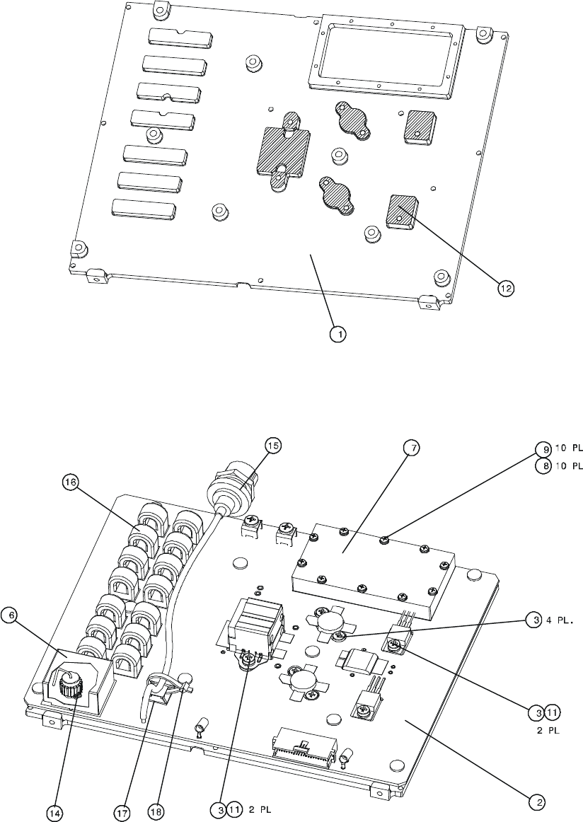
MM-E 2072-09333-00
B-74
Figure B-4.A. HI POWER Module, Identification of Components (Sheet 1 of 3)
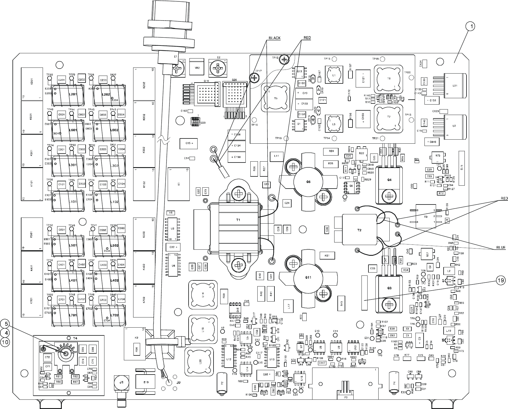
MM-E 2072-09333-00
COMPONENT SIDE
Figure B-4.B. HI POWER Module, Identification of Components (Sheet 2 of 3)
B-75/B-76
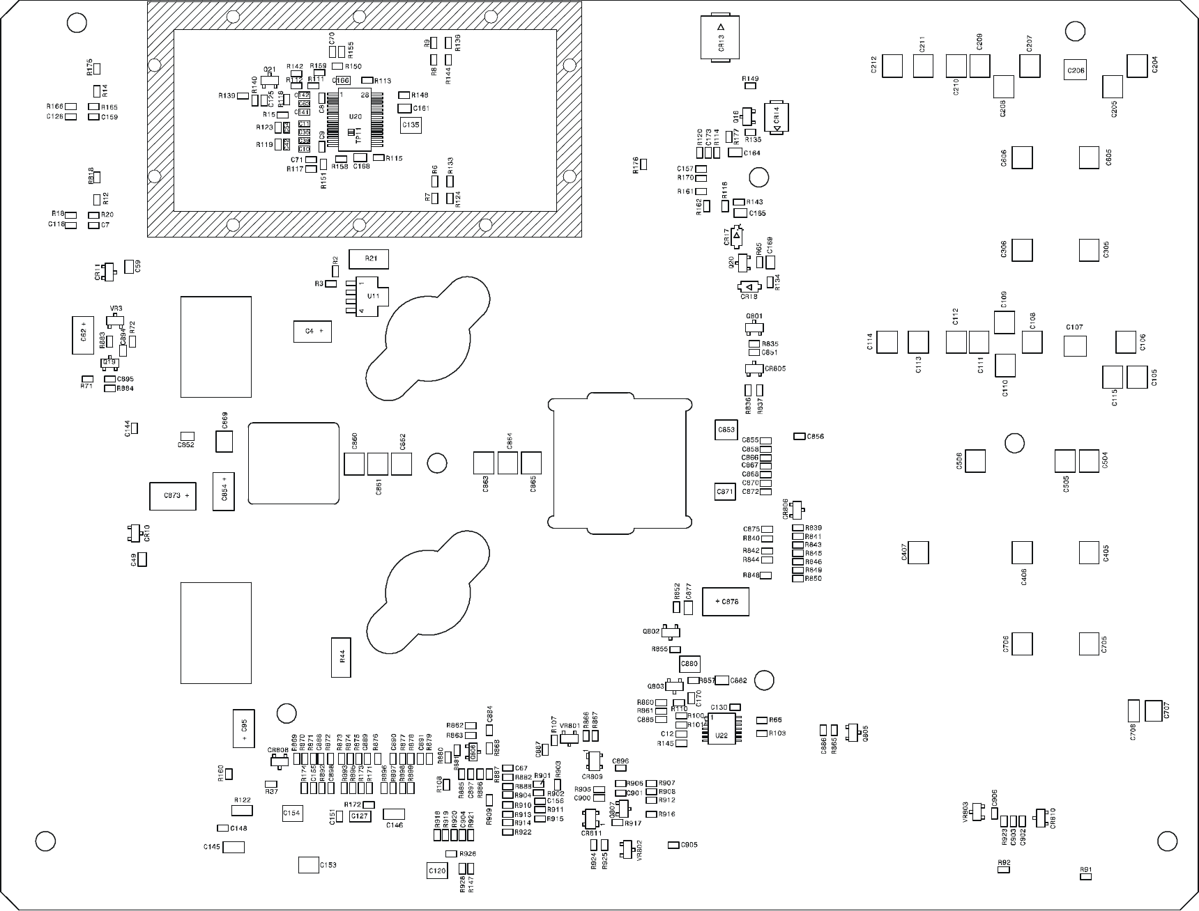
MM-E 2072-09333-00
PRINT SIDE
Figure B-4.C. HI POWER Module, Identification of Components (Sheet 3 of 3)
B-77/B-78
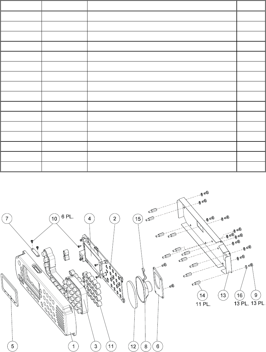
MM-E 2072-09333-00
B-79
Table B-5. Dash Front Panel, Control Head Assembly, Parts List
Ref. Des. Mfg. Catalog No.
Description Qty.
2072-90833-00 DASH FRONT PANEL ASSY Figure B-5
BL1 2072-45001-10 FRONT PANEL 1.0
BL2 2072-95211-00 DASH FRONT PANEL MODULE 1.0
BL3 2072-45004-00 KEYPAD 1.0
BL4 2072-90115-00 DISPLAY ASSY 1.0
BL5 2072-45007-00 WINDOW, LC 1.0
BL6 2072-45008-00 HOLDER SPEAKER 1.0
BL7 2072-45020-00 PLUG 1.0
BL8 2072-31050-00 SPEAKER (MIRS) 5002236P 1.0
BL9 4052-15003-00 SCREW, CROSS RECESSED, PAN HEAD 13.0
BL10 2072-45030-00 SCREW, M2X6, PH, BLACK 6.0
BL11 2072-45036-00 INSERT 1.0
BL12 2072-56010-00 GASKET, SPEAKER ROGG. 32 1.0
BL13 2072-45033-00 RF SHIELD 1.0
BL14 2072-45034-00 SPACER 11.0
BL15 2072-90150-00 SPEAKER CABLE 1.0
Figure B-5. Dash Front Panel, Control Head Assembly

MM-E 2072-09333-00
B-80
Table B-6. CONTROL HEAD Module (Dash Mount Version), Parts List
Ref. Des. Mfg. Catalog No.
Description Qty.
2072-95211-00 DASH FRONT PANEL MODULE Figure B-6
BL1 2072-32211-00 FRONT PANEL PCB 1.0
BL2 2072-45003-00 STUD FOR MICOM-Z 4.0
C1 4017-20153-00 CAPACITOR, CHIP, CERAMIC, 2.2UF, 25V 1.0
C2 4017-20153-00 CAPACITOR, CHIP, CERAMIC, 2.2UF, 25V 1.0
C3 4017-20153-00 CAPACITOR, CHIP, CERAMIC, 2.2UF, 25V 1.0
C4 4017-20153-00 CAPACITOR, CHIP, CERAMIC, 2.2UF, 25V 1.0
C5 4017-20153-00 CAPACITOR, CHIP, CERAMIC, 2.2UF, 25V 1.0
C6 4017-20153-00 CAPACITOR, CHIP, CERAMIC, 2.2UF, 25V 1.0
C7 4017-20153-00 CAPACITOR, CHIP, CERAMIC, 2.2UF, 25V 1.0
C8 4017-20153-00 CAPACITOR, CHIP, CERAMIC, 2.2UF, 25V 1.0
C9 4017-20153-00 CAPACITOR, CHIP, CERAMIC, 2.2UF, 25V 1.0
C10 4017-20153-00 CAPACITOR, CHIP, CERAMIC, 2.2UF, 25V 1.0
C11 4017-20153-00 CAPACITOR, CHIP, CERAMIC, 2.2UF, 25V 1.0
C12 4017-20153-00 CAPACITOR, CHIP, CERAMIC, 2.2UF, 25V 1.0
C13 4017-20153-00 CAPACITOR, CHIP, CERAMIC, 2.2UF, 25V 1.0
C14 4017-20109-25 CAPACITOR, CHIP, X7R, 10UF 1.0
C15 4017-20192-00 CAPACITOR, 1210, X7R, 4.7UF, 50V 1.0
C16 4017-20192-00 CAPACITOR, 1210, X7R, 4.7UF, 50V 1.0
C19 4017-25265-10 CAPACITOR, CHIP, NP0, 33PF, 1% 1.0
C20 4017-25265-10 CAPACITOR, CHIP, NP0, 33PF, 1% 1.0
C21 4017-25282-00 CAPACITOR, CHIP, CG, 1NF, 5% 1.0
C22 4017-20284-00 CAPACITOR, CHIP, CERAMIC, 100NF, 16V 1.0
C23 4017-20284-00 CAPACITOR, CHIP, CERAMIC, 100NF, 16V 1.0
C24 4017-20284-00 CAPACITOR, CHIP, CERAMIC, 100NF, 16V 1.0
C25 4017-20284-00 CAPACITOR, CHIP, CERAMIC, 100NF, 16V 1.0
C26 4017-20284-00 CAPACITOR, CHIP, CERAMIC, 100NF, 16V 1.0
C27 4017-20192-00 CAPACITOR, 1210, X7R, 4.7UF, 50V 1.0
C32 4017-20284-00 CAPACITOR, CHIP, CERAMIC, 100NF, 16V 1.0
C33 4017-25282-00 CAPACITOR, CHIP, CG, 1NF, 5% 1.0
C35 4017-25282-00 CAPACITOR, CHIP, CG, 1NF, 5% 1.0
C36 4017-25282-00 CAPACITOR, CHIP, CG, 1NF, 5% 1.0
C39 4017-25282-00 CAPACITOR, CHIP, CG, 1NF, 5% 1.0
C42 4017-20192-00 CAPACITOR, 1210, X7R, 4.7UF, 50V 1.0
C43 4017-25282-00 CAPACITOR, CHIP, CG, 1NF, 5% 1.0
C44 4017-20284-00 CAPACITOR, CHIP, CERAMIC, 100NF, 16V 1.0
C45 4017-20284-00 CAPACITOR, CHIP, CERAMIC, 100NF, 16V 1.0
C46 4017-20284-00 CAPACITOR, CHIP, CERAMIC, 100NF, 16V 1.0
C47 4017-20161-00 CAPACITOR, CHIP, X7R, 1UF, 10V 1.0
C53 4017-20109-25 CAPACITOR, CHIP, X7R, 10UF 1.0

MM-E 2072-09333-00
B-81
Table B-6. CONTROL HEAD Module (Dash Mount Version), Parts List (Cont’d)
Ref. Des. Mfg. Catalog No.
Description Qty.
C54 4017-20192-00 CAPACITOR, 1210, X7R, 4.7UF, 50V 1.0
C59 4017-20284-00 CAPACITOR, CHIP, CERAMIC, 100NF, 16V 1.0
C60 4017-20284-00 CAPACITOR, CHIP, CERAMIC, 100NF, 16V 1.0
C61 4017-25271-00 CAPACITOR, CHIP, CG, 100PF, 5% 1.0
C62 4017-25271-00 CAPACITOR, CHIP, CG, 100PF, 5% 1.0
C63 4017-25271-00 CAPACITOR, CHIP, CG, 100PF, 5% 1.0
C64 4017-25271-00 CAPACITOR, CHIP, CG, 100PF, 5% 1.0
C65 4017-25271-00 CAPACITOR, CHIP, CG, 100PF, 5% 1.0
C66 4017-25263-10 CAPACITOR, CHIP, NP0, 22PF, 1% 1.0
C67 4017-25263-10 CAPACITOR, CHIP, NP0, 22PF, 1% 1.0
C68 4017-25263-10 CAPACITOR, CHIP, NP0, 22PF, 1% 1.0
C69 4017-25263-10 CAPACITOR, CHIP, NP0, 22PF, 1% 1.0
C70 4017-20192-00 CAPACITOR, 1210, X7R, 4.7UF, 50V 1.0
C71 4017-20192-00 CAPACITOR, 1210, X7R, 4.7UF, 50V 1.0
C72 4017-20192-00 CAPACITOR, 1210, X7R, 4.7UF, 50V 1.0
C73 4017-20192-00 CAPACITOR, 1210, X7R, 4.7UF, 50V 1.0
C74 4017-20192-00 CAPACITOR, 1210, X7R, 4.7UF, 50V 1.0
C76 4017-20192-00 CAPACITOR, 1210, X7R, 4.7UF, 50V 1.0
C78 4017-20284-00 CAPACITOR, CHIP, CERAMIC, 100NF, 16V 1.0
C79 4017-80304-00 CAPACITOR, 47UF, 35V 1.0
C80 4017-20191-00 CAPACITOR, 1210, X7R, 1UF, 100V 1.0
C81 4017-20165-00 CAPACITOR, CHIP, CERAMIC, 100NF, 50V 1.0
C82 4017-20191-00 CAPACITOR, 1210, X7R, 1UF, 100V 1.0
C83 4017-80304-00 CAPACITOR, 47UF, 35V 1.0
C84 2089-17202-00 CAPACITOR, 1812, X7R, 15UF, 25V 1.0
C85 4017-20192-00 CAPACITOR, 1210, X7R, 4.7UF, 50V 1.0
C86 4017-20165-00 CAPACITOR, CHIP, CERAMIC, 100NF, 50V 1.0
C87 4017-20165-00 CAPACITOR, CHIP, CERAMIC, 100NF, 50V 1.0
C88 4017-20165-00 CAPACITOR, CHIP, CERAMIC, 100NF, 50V 1.0
C89 4017-20165-00 CAPACITOR, CHIP, CERAMIC, 100NF, 50V 1.0
C90 4017-25286-00 CAPACITOR, CHIP, C0G, 100PF, 1% 1.0
C91 4017-20165-00 CAPACITOR, CHIP, CERAMIC, 100NF, 50V 1.0
C92 4017-20165-00 CAPACITOR, CHIP, CERAMIC, 100NF, 50V 1.0
C93 4017-20165-00 CAPACITOR, CHIP, CERAMIC, 100NF, 50V 1.0
C94 4017-25275-00 CAPACITOR, CHIP, CG, 220PF, 5% 1.0
C95 4017-20165-00 CAPACITOR, CHIP, CERAMIC, 100NF, 50V 1.0
C96 4017-25263-10 CAPACITOR, CHIP, NP0, 22PF, 1% 1.0
C97 4017-20192-00 CAPACITOR, 1210, X7R, 4.7UF, 50V 1.0
C98 2089-17202-00 CAPACITOR, 1812, X7R, 15UF, 25V 1.0
C99 2089-17202-00 CAPACITOR, 1812, X7R, 15UF, 25V 1.0

MM-E 2072-09333-00
B-82
Table B-6. CONTROL HEAD Module (Dash Mount Version), Parts List (Cont’d)
Ref. Des. Mfg. Catalog No.
Description Qty.
C121 4017-20284-00 CAPACITOR, CHIP, CERAMIC, 100NF, 16V 1.0
C501 4017-25282-00 CAPACITOR, CHIP, CG, 1NF, 5% 1.0
C502 4017-25274-00 CAPACITOR, 0603, NP0, 180PF, 50V 1.0
C503 4017-25274-00 CAPACITOR, 0603, NP0, 180PF, 50V 1.0
C504 4017-25274-00 CAPACITOR, 0603, NP0, 180PF, 50V 1.0
C505 4017-25274-00 CAPACITOR, 0603, NP0, 180PF, 50V 1.0
C506 4017-20284-00 CAPACITOR, CHIP, CERAMIC, 100NF, 16V 1.0
C513 4017-20165-00 CAPACITOR, CHIP, CERAMIC, 100NF, 50V 1.0
C544 4017-20192-00 CAPACITOR, 1210, X7R, 4.7UF, 50V 1.0
C545 4017-20578-00 CAPACITOR, CHIP, 0402, 100NF 1.0
C550 4017-25282-00 CAPACITOR, CHIP, CG, 1NF, 5% 1.0
C551 4017-20192-00 CAPACITOR, 1210, X7R, 4.7UF, 50V 1.0
C552 4017-20109-25 CAPACITOR, CHIP, X7R, 10UF 1.0
C553 4017-20284-00 CAPACITOR, CHIP, CERAMIC, 100NF, 16V 1.0
C554 4017-20578-00 CAPACITOR, CHIP, 0402, 100NF 1.0
C555 4017-20578-00 CAPACITOR, CHIP, 0402, 100NF 1.0
CR2 4021-10403-35 DIODE, RECTIFIER, SCHOTTKY, MBRS360 1.0
CR501 4021-10098-35 DIODE, SWITCHING 1.0
DS1 4021-80052-35 LED, GREEN 1.0
DS2 4021-80052-35 LED, GREEN 1.0
DS3 4021-80052-35 LED, GREEN 1.0
DS4 4021-80052-35 LED, GREEN 1.0
DS5 4021-80052-35 LED, GREEN 1.0
DS6 4021-80052-35 LED, GREEN 1.0
DS7 4021-80052-35 LED, GREEN 1.0
DS8 4021-80052-35 LED, GREEN 1.0
DS9 4021-80052-35 LED, GREEN 1.0
DS10 4021-80052-35 LED, GREEN 1.0
DS11 4021-80052-35 LED, GREEN 1.0
DS12 4021-80052-35 LED, GREEN 1.0
DS13 4021-80052-35 LED, GREEN 1.0
DS14 4021-80052-35 LED, GREEN 1.0
DS15 4021-80052-35 LED, GREEN 1.0
DS16 4021-80052-35 LED, GREEN 1.0
DS17 4021-80052-35 LED, GREEN 1.0
DS18 4021-80052-35 LED, GREEN 1.0
DS19 4021-80052-35 LED, GREEN 1.0
DS20 4021-80052-35 LED, GREEN 1.0
DS21 4021-80052-35 LED, GREEN 1.0
DS22 4021-80052-35 LED, GREEN 1.0

MM-E 2072-09333-00
B-83
Table B-6. CONTROL HEAD Module (Dash Mount Version), Parts List (Cont’d)
Ref. Des. Mfg. Catalog No.
Description Qty.
DS23 4021-80052-35 LED, GREEN 1.0
DS24 4021-80052-35 LED, GREEN 1.0
DS25 4021-80052-35 LED, GREEN 1.0
DS26 4021-80052-35 LED, GREEN 1.0
DS27 4021-80052-35 LED, GREEN 1.0
E19 4018-60017-00 BEAD, EMI, 60 OHM, 500mA 1.0
E20 4018-60030-00 BEAD, EMI, 75 OHM, 200mA 1.0
E26 4018-60017-00 BEAD, EMI, 60 OHM, 500mA 1.0
E27 4018-60030-00 BEAD, EMI, 75 OHM, 200mA 1.0
E28 4018-60030-00 BEAD, EMI, 75 OHM, 200mA 1.0
E29 4018-60030-00 BEAD, EMI, 75 OHM, 200mA 1.0
E502 4018-60017-00 BEAD, EMI, 60 OHM, 500mA 1.0
J3 4033-60109-00 CONNECTOR, FPC/FFC, 40S 1.0
J4 4033-53021-00 SD MEMORY CARD CONNECTOR 1.0
L1 4018-12052-00 COIL, FIXED, 4.7UH 1.0
L2 4018-12052-00 COIL, FIXED, 4.7UH 1.0
L3 4018-12052-00 COIL, FIXED, 4.7UH 1.0
L4 4018-12052-00 COIL, FIXED, 4.7UH 1.0
L5 4018-12052-00 COIL, FIXED, 4.7UH 1.0
L6 4018-12052-00 COIL, FIXED, 4.7UH 1.0
L7 4018-12052-00 COIL, FIXED, 4.7UH 1.0
L8 4018-10116-00 INDUCTOR, 33UH 1.0
P1 4033-51109-01 CONNECTOR, 2 PIN, 1.25mm 1.0
P2 4033-51109-01 CONNECTOR, 2 PIN, 1.25mm 1.0
P3 4033-51201-01 HEADER, 24PIN 1.0
P4 4033-51007-01 HEADER, 2PIN 1.0
P5 4033-50225-01 STRIP, DOUBLE ROW, 5 PIN 1.0
P6 2072-33325-00 CONNECTOR, MICROPHONE 1.0
P7 4033-50212-01 STRIP, SINGLE ROW, 2 PIN 1.0
Q1 4021-00183-35 MOSFET, P-CHANNEL 1.0
Q2 4021-00299-35 MOSFET, N-CHANNEL 1.0
Q3 4021-00202-35 TRANSISTOR, NPN, MMBT2222A 1.0
Q4 4021-00202-35 TRANSISTOR, NPN, MMBT2222A 1.0
Q7 4021-00415-35 FET 1.0
Q501 4021-00415-35 FET 1.0
Q502 4021-00415-35 FET 1.0
Q503 4021-00341-35 TRANSISTOR, PNP 1.0
Q504 4021-00341-35 TRANSISTOR, PNP 1.0
Q505 4021-00415-35 FET 1.0
Q506 4021-00415-35 FET 1.0

MM-E 2072-09333-00
B-84
Table B-6. CONTROL HEAD Module (Dash Mount Version), Parts List (Cont’d)
Ref. Des. Mfg. Catalog No.
Description Qty.
Q507 4021-00415-35 FET 1.0
R1 4016-20000-50 RESISTOR, CHIP, 0603, JUMPER 1.0
R2 4016-11009-10 RESISTOR, CHIP, 10.0K, 1%, 1/8W 1.0
R3 4016-21002-10 RESISTOR, 10.0K, 1%, 1/16W 1.0
R4 4016-21002-10 RESISTOR, 10.0K, 1%, 1/16W 1.0
R5 4016-21002-10 RESISTOR, 10.0K, 1%, 1/16W 1.0
R9 4016-22210-10 RESISTOR, 221, 1%, 1/16W 1.0
R12 4016-21004-10 RESISTOR, 1.0M, 1%, 1/16W 1.0
R13 4016-21009-10 RESISTOR, CHIP, 0603, 10, 1% 1.0
R14 4016-21009-10 RESISTOR, CHIP, 0603, 10, 1% 1.0
R15 4016-24751-10 RESISTOR, 4.75K, 1%, 1/16W 1.0
R16 4016-24751-10 RESISTOR, 4.75K, 1%, 1/16W 1.0
R17 4016-21001-10 RESISTOR, 1.00K, 1%, 1/16W 1.0
R18 4016-21003-10 RESISTOR, 100K, 1%, 1/16W 1.0
R19 4016-52219-10 RESISTOR, CHIP, 0402, 22.1 1.0
R20 4016-52219-10 RESISTOR, CHIP, 0402, 22.1 1.0
R21 4016-52219-10 RESISTOR, CHIP, 0402, 22.1 1.0
R22 4016-52219-10 RESISTOR, CHIP, 0402, 22.1 1.0
R23 4016-52219-10 RESISTOR, CHIP, 0402, 22.1 1.0
R24 4016-52219-10 RESISTOR, CHIP, 0402, 22.1 1.0
R25 4016-21212-10 RESISTOR, 12.1K, 1%, 1/16W 1.0
R26 4016-52219-10 RESISTOR, CHIP, 0402, 22.1 1.0
R27 4016-52219-10 RESISTOR, CHIP, 0402, 22.1 1.0
R28 4016-52219-10 RESISTOR, CHIP, 0402, 22.1 1.0
R29 4016-52219-10 RESISTOR, CHIP, 0402, 22.1 1.0
R30 4016-52219-10 RESISTOR, CHIP, 0402, 22.1 1.0
R31 4016-52219-10 RESISTOR, CHIP, 0402, 22.1 1.0
R32 4016-52219-10 RESISTOR, CHIP, 0402, 22.1 1.0
R33 4016-52219-10 RESISTOR, CHIP, 0402, 22.1 1.0
R34 4016-52219-10 RESISTOR, CHIP, 0402, 22.1 1.0
R35 4016-52219-10 RESISTOR, CHIP, 0402, 22.1 1.0
R36 4016-52219-10 RESISTOR, CHIP, 0402, 22.1 1.0
R37 4016-21004-10 RESISTOR, 1.0M, 1%, 1/16W 1.0
R38 4016-52219-10 RESISTOR, CHIP, 0402, 22.1 1.0
R39 4016-52219-10 RESISTOR, CHIP, 0402, 22.1 1.0
R40 4016-52219-10 RESISTOR, CHIP, 0402, 22.1 1.0
R41 4016-52219-10 RESISTOR, CHIP, 0402, 22.1 1.0
R42 4016-52219-10 RESISTOR, CHIP, 0402, 22.1 1.0
R43 4016-52219-10 RESISTOR, CHIP, 0402, 22.1 1.0
R44 4016-52219-10 RESISTOR, CHIP, 0402, 22.1 1.0

MM-E 2072-09333-00
B-85
Table B-6. CONTROL HEAD Module (Dash Mount Version), Parts List (Cont’d)
Ref. Des. Mfg. Catalog No.
Description Qty.
R45 4016-52219-10 RESISTOR, CHIP, 0402, 22.1 1.0
R46 4016-52219-10 RESISTOR, CHIP, 0402, 22.1 1.0
R47 4016-52219-10 RESISTOR, CHIP, 0402, 22.1 1.0
R48 4016-52219-10 RESISTOR, CHIP, 0402, 22.1 1.0
R49 4016-52219-10 RESISTOR, CHIP, 0402, 22.1 1.0
R50 4016-52219-10 RESISTOR, CHIP, 0402, 22.1 1.0
R51 4016-52219-10 RESISTOR, CHIP, 0402, 22.1 1.0
R52 4016-52219-10 RESISTOR, CHIP, 0402, 22.1 1.0
R53 4016-52219-10 RESISTOR, CHIP, 0402, 22.1 1.0
R54 4016-52219-10 RESISTOR, CHIP, 0402, 22.1 1.0
R55 4016-52219-10 RESISTOR, CHIP, 0402, 22.1 1.0
R56 4016-52219-10 RESISTOR, CHIP, 0402, 22.1 1.0
R57 4016-52219-10 RESISTOR, CHIP, 0402, 22.1 1.0
R58 4016-52219-10 RESISTOR, CHIP, 0402, 22.1 1.0
R59 4016-52219-10 RESISTOR, CHIP, 0402, 22.1 1.0
R60 4016-52219-10 RESISTOR, CHIP, 0402, 22.1 1.0
R61 4016-52219-10 RESISTOR, CHIP, 0402, 22.1 1.0
R62 4016-52219-10 RESISTOR, CHIP, 0402, 22.1 1.0
R63 4016-52219-10 RESISTOR, CHIP, 0402, 22.1 1.0
R64 4016-52219-10 RESISTOR, CHIP, 0402, 22.1 1.0
R65 4016-52219-10 RESISTOR, CHIP, 0402, 22.1 1.0
R66 4016-52219-10 RESISTOR, CHIP, 0402, 22.1 1.0
R67 4016-52219-10 RESISTOR, CHIP, 0402, 22.1 1.0
R68 4016-52219-10 RESISTOR, CHIP, 0402, 22.1 1.0
R69 4016-52219-10 RESISTOR, CHIP, 0402, 22.1 1.0
R70 4016-52219-10 RESISTOR, CHIP, 0402, 22.1 1.0
R71 4016-52219-10 RESISTOR, CHIP, 0402, 22.1 1.0
R72 4016-52219-10 RESISTOR, CHIP, 0402, 22.1 1.0
R73 4016-52219-10 RESISTOR, CHIP, 0402, 22.1 1.0
R74 4016-52219-10 RESISTOR, CHIP, 0402, 22.1 1.0
R75 4016-52219-10 RESISTOR, CHIP, 0402, 22.1 1.0
R76 4016-52219-10 RESISTOR, CHIP, 0402, 22.1 1.0
R77 4016-52219-10 RESISTOR, CHIP, 0402, 22.1 1.0
R78 4016-52219-10 RESISTOR, CHIP, 0402, 22.1 1.0
R79 4016-52219-10 RESISTOR, CHIP, 0402, 22.1 1.0
R80 4016-52219-10 RESISTOR, CHIP, 0402, 22.1 1.0
R81 4016-50000-50 RESISTOR, CHIP, 0402, JUMPER 1.0
R82 4016-50000-50 RESISTOR, CHIP, 0402, JUMPER 1.0
R83 4016-50000-50 RESISTOR, CHIP, 0402, JUMPER 1.0
R84 4016-50000-50 RESISTOR, CHIP, 0402, JUMPER 1.0

MM-E 2072-09333-00
B-86
Table B-6. CONTROL HEAD Module (Dash Mount Version), Parts List (Cont’d)
Ref. Des. Mfg. Catalog No.
Description Qty.
R85 4016-50000-50 RESISTOR, CHIP, 0402, JUMPER 1.0
R86 4016-50000-50 RESISTOR, CHIP, 0402, JUMPER 1.0
R87 4016-51002-10 RESISTOR, CHIP, MF, 10K, 0.06W 1.0
R88 4016-52219-10 RESISTOR, CHIP, 0402, 22.1 1.0
R89 4016-52219-10 RESISTOR, CHIP, 0402, 22.1 1.0
R90 4016-52219-10 RESISTOR, CHIP, 0402, 22.1 1.0
R91 4016-52219-10 RESISTOR, CHIP, 0402, 22.1 1.0
R92 4016-52219-10 RESISTOR, CHIP, 0402, 22.1 1.0
R93 4016-51002-10 RESISTOR, CHIP, MF, 10K, 0.06W 1.0
R94 4016-51002-10 RESISTOR, CHIP, MF, 10K, 0.06W 1.0
R95 4016-51002-10 RESISTOR, CHIP, MF, 10K, 0.06W 1.0
R96 4016-51002-10 RESISTOR, CHIP, MF, 10K, 0.06W 1.0
R97 4016-51002-10 RESISTOR, CHIP, MF, 10K, 0.06W 1.0
R98 4016-51002-10 RESISTOR, CHIP, MF, 10K, 0.06W 1.0
R99 4016-51002-10 RESISTOR, CHIP, MF, 10K, 0.06W 1.0
R100 4016-51002-10 RESISTOR, CHIP, MF, 10K, 0.06W 1.0
R101 4016-51002-10 RESISTOR, CHIP, MF, 10K, 0.06W 1.0
R102 4016-51002-10 RESISTOR, CHIP, MF, 10K, 0.06W 1.0
R103 4016-51002-10 RESISTOR, CHIP, MF, 10K, 0.06W 1.0
R104 4016-51002-10 RESISTOR, CHIP, MF, 10K, 0.06W 1.0
R105 4016-51002-10 RESISTOR, CHIP, MF, 10K, 0.06W 1.0
R106 4016-51002-10 RESISTOR, CHIP, MF, 10K, 0.06W 1.0
R107 4016-51002-10 RESISTOR, CHIP, MF, 10K, 0.06W 1.0
R108 4016-51002-10 RESISTOR, CHIP, MF, 10K, 0.06W 1.0
R109 4016-51002-10 RESISTOR, CHIP, MF, 10K, 0.06W 1.0
R110 4016-51002-10 RESISTOR, CHIP, MF, 10K, 0.06W 1.0
R111 4016-51002-10 RESISTOR, CHIP, MF, 10K, 0.06W 1.0
R112 4016-51002-10 RESISTOR, CHIP, MF, 10K, 0.06W 1.0
R113 4016-51002-10 RESISTOR, CHIP, MF, 10K, 0.06W 1.0
R114 4016-52219-10 RESISTOR, CHIP, 0402, 22.1 1.0
R115 4016-52219-10 RESISTOR, CHIP, 0402, 22.1 1.0
R116 4016-52219-10 RESISTOR, CHIP, 0402, 22.1 1.0
R117 4016-52219-10 RESISTOR, CHIP, 0402, 22.1 1.0
R118 4016-51002-10 RESISTOR, CHIP, MF, 10K, 0.06W 1.0
R119 4016-51002-10 RESISTOR, CHIP, MF, 10K, 0.06W 1.0
R120 4016-51002-10 RESISTOR, CHIP, MF, 10K, 0.06W 1.0
R121 4016-51002-10 RESISTOR, CHIP, MF, 10K, 0.06W 1.0
R122 4016-21500-10 RESISTOR, CHIP, MF, 150E, 0.063W 1.0
R123 4016-21500-10 RESISTOR, CHIP, MF, 150E, 0.063W 1.0
R124 4016-21500-10 RESISTOR, CHIP, MF, 150E, 0.063W 1.0

MM-E 2072-09333-00
B-87
Table B-6. CONTROL HEAD Module (Dash Mount Version), Parts List (Cont’d)
Ref. Des. Mfg. Catalog No.
Description Qty.
R125 4016-21500-10 RESISTOR, CHIP, MF, 150E, 0.063W 1.0
R126 4016-21500-10 RESISTOR, CHIP, MF, 150E, 0.063W 1.0
R127 4016-11500-10 RESISTOR, CHIP, 150, 1%, 1/8W 1.0
R128 4016-11500-10 RESISTOR, CHIP, 150, 1%, 1/8W 1.0
R133 4016-21002-10 RESISTOR, 10.0K, 1%, 1/16W 1.0
R137 4016-22002-10 RESISTOR, 20.0K, 1%, 1/16W 1.0
R138 4016-22002-10 RESISTOR, 20.0K, 1%, 1/16W 1.0
R139 4016-22002-10 RESISTOR, 20.0K, 1%, 1/16W 1.0
R140 4016-22002-10 RESISTOR, 20.0K, 1%, 1/16W 1.0
R141 4016-22002-10 RESISTOR, 20.0K, 1%, 1/16W 1.0
R142 4016-11500-10 RESISTOR, CHIP, 150, 1%, 1/8W 1.0
R143 4016-25112-10 RESISTOR, 51.1K, 1%, 1/16W 1.0
R144 4016-25112-10 RESISTOR, 51.1K, 1%, 1/16W 1.0
R145 4016-25112-10 RESISTOR, 51.1K, 1%, 1/16W 1.0
R146 4016-25112-10 RESISTOR, 51.1K, 1%, 1/16W 1.0
R151 4016-21000-10 RESISTOR, 100, 1%, 1/16W 1.0
R152 4016-20000-50 RESISTOR, CHIP, 0603, JUMPER 1.0
R155 4016-20000-50 RESISTOR, CHIP, 0603, JUMPER 1.0
R156 4016-10519-50 RESISTOR, CHIP, 5.1, 5%, 1/8W 1.0
R157 4016-13011-10 RESISTOR, CHIP, 3.01K, 1%, 1/8W 1.0
R158 4016-14751-10 RESISTOR, CHIP, 4.75K, 1%, 1/8W 1.0
R159 4016-15111-10 RESISTOR, CHIP, 5.11K, 1%, 1/8W 1.0
R160 4016-25110-10 RESISTOR, 511, 1%, 1/16W 1.0
R166 4016-21009-10 RESISTOR, CHIP, 0603, 10, 1% 1.0
R167 4016-14750-10 RESISTOR, CHIP, 475, 1%, 1/8W 1.0
R170 4016-23329-10 RESISTOR, CHIP, 0603, 33.2, 1% 1.0
R177 4016-20000-50 RESISTOR, CHIP, 0603, JUMPER 1.0
R178 4016-23011-10 RESISTOR, 3.01K, 1%, 1/16W 1.0
R181 4016-20000-50 RESISTOR, CHIP, 0603, JUMPER 1.0
R186 4016-21002-10 RESISTOR, 10.0K, 1%, 1/16W 1.0
R187 4016-21002-10 RESISTOR, 10.0K, 1%, 1/16W 1.0
R193 4016-24121-10 RESISTOR, 4.12K, 1%, 1/16W 1.0
R194 4016-23012-10 RESISTOR, CHIP, 0603, 30.1K, 1% 1.0
R195 4016-31900-10 RESISTOR, CHIP, 0.1, 1%, 1W 1.0
R196 4016-31900-10 RESISTOR, CHIP, 0.1, 1%, 1W 1.0
R197 4016-23162-10 RESISTOR, CHIP, 0603, 31.6K, 1% 1.0
R198 4016-24751-10 RESISTOR, 4.75K, 1%, 1/16W 1.0
R201 4016-43329-10 RESISTOR, CHIP, 33.2, 1%, 1W 1.0
R202 4016-43329-10 RESISTOR, CHIP, 33.2, 1%, 1W 1.0
R203 4016-43329-10 RESISTOR, CHIP, 33.2, 1%, 1W 1.0

MM-E 2072-09333-00
B-88
Table B-6. CONTROL HEAD Module (Dash Mount Version), Parts List (Cont’d)
Ref. Des. Mfg. Catalog No.
Description Qty.
R204 4016-43329-10 RESISTOR, CHIP, 33.2, 1%, 1W 1.0
R206 4016-25111-10 RESISTOR, 5.11K, 1%, 1/16W 1.0
R207 4016-25111-10 RESISTOR, 5.11K, 1%, 1/16W 1.0
R212 4016-22213-10 RESISTOR, 221K, 1%, 1/16W 1.0
R213 4016-20000-50 RESISTOR, CHIP, 0603, JUMPER 1.0
R214 4016-20000-50 RESISTOR, CHIP, 0603, JUMPER 1.0
R215 4016-20000-50 RESISTOR, CHIP, 0603, JUMPER 1.0
R220 4016-21009-10 RESISTOR, CHIP, 0603, 10, 1% 1.0
R221 4016-21009-10 RESISTOR, CHIP, 0603, 10, 1% 1.0
R222 4016-52219-10 RESISTOR, CHIP, 0402, 22.1 1.0
R223 4016-52219-10 RESISTOR, CHIP, 0402, 22.1 1.0
R226 4016-21009-10 RESISTOR, CHIP, 0603, 10, 1% 1.0
R229 4016-24751-10 RESISTOR, 4.75K, 1%, 1/16W 1.0
R233 4016-14129-10 RESISTOR, CHIP, 41.2, 1%, 1/8W 1.0
R502 4016-20000-50 RESISTOR, CHIP, 0603, JUMPER 1.0
R507 4016-21000-10 RESISTOR, 100, 1%, 1/16W 1.0
R508 4016-21000-10 RESISTOR, 100, 1%, 1/16W 1.0
R509 4016-21000-10 RESISTOR, 100, 1%, 1/16W 1.0
R512 4016-25110-10 RESISTOR, 511, 1%, 1/16W 1.0
R513 4016-21001-10 RESISTOR, 1.00K, 1%, 1/16W 1.0
R514 4016-21001-10 RESISTOR, 1.00K, 1%, 1/16W 1.0
R515 4016-21101-10 RESISTOR, 1.10K, 1%, 1/16W 1.0
R516 4016-23011-10 RESISTOR, 3.01K, 1%, 1/16W 1.0
R517 4016-21000-10 RESISTOR, 100, 1%, 1/16W 1.0
R518 4016-21002-10 RESISTOR, 10.0K, 1%, 1/16W 1.0
R519 4016-21002-10 RESISTOR, 10.0K, 1%, 1/16W 1.0
R520 4016-21000-10 RESISTOR, 100, 1%, 1/16W 1.0
R521 4016-21002-10 RESISTOR, 10.0K, 1%, 1/16W 1.0
R522 4016-21002-10 RESISTOR, 10.0K, 1%, 1/16W 1.0
R523 4016-21002-10 RESISTOR, 10.0K, 1%, 1/16W 1.0
R524 4016-21002-10 RESISTOR, 10.0K, 1%, 1/16W 1.0
R525 4016-21002-10 RESISTOR, 10.0K, 1%, 1/16W 1.0
R527 4016-21002-10 RESISTOR, 10.0K, 1%, 1/16W 1.0
R528 4016-21002-10 RESISTOR, 10.0K, 1%, 1/16W 1.0
R529 4016-21101-10 RESISTOR, 1.10K, 1%, 1/16W 1.0
R530 4016-43329-10 RESISTOR, CHIP, 33.2, 1%, 1W 1.0
R531 4016-20000-50 RESISTOR, CHIP, 0603, JUMPER 1.0
R532 4016-20000-50 RESISTOR, CHIP, 0603, JUMPER 1.0
R533 4016-21101-10 RESISTOR, 1.10K, 1%, 1/16W 1.0
R535 4016-60000-50 RESISTOR, CHIP, 0 OHM, 1/2W 1.0

MM-E 2072-09333-00
B-89
Table B-6. CONTROL HEAD Module (Dash Mount Version), Parts List (Cont’d)
Ref. Des. Mfg. Catalog No.
Description Qty.
R536 4016-18251-10 RESISTOR, CHIP, 8.25K, 1%, 1/8W 1.0
R538 4016-24029-10 RESISTOR, CHIP, 0603, 40.2, 1% 1.0
R539 4016-23329-10 RESISTOR, CHIP, 0603, 33.2, 1% 1.0
R541 4016-28669-10 RESISTOR, CHIP, 0603, 86.6, 1% 1.0
R563 4016-21101-10 RESISTOR, 1.10K, 1%, 1/16W 1.0
R569 4016-21101-10 RESISTOR, 1.10K, 1%, 1/16W 1.0
R581 4016-12671-10 RESISTOR, CHIP, 2.67K, 1%, 1/8W 1.0
R582 4016-20000-50 RESISTOR, CHIP, 0603, JUMPER 1.0
R583 4016-21101-10 RESISTOR, 1.10K, 1%, 1/16W 1.0
R584 4016-50000-50 RESISTOR, CHIP, 0402, JUMPER 1.0
R601 4016-21002-10 RESISTOR, 10.0K, 1%, 1/16W 1.0
R602 4016-25110-10 RESISTOR, 511, 1%, 1/16W 1.0
RT1 4016-91103-20 THERMISTOR, NTC 1.0
SW26 2036-31016-00 SWITCH, DPDT, LOCKING 1.0
T1 4018-10178-00 TRANSFORMER, DUAL WINDING, SHIELDED 1.0
U1 4021-50043-64 MICROCONTROLLER, 8051 1.0
U3 4021-31132-50 SCHMITT TRIGGER, 74HC132 1.0
U4 4021-22111-54 VOLTAGE REGULATOR, 3.3V 1.0
U5 4021-22108-54 VOLTAGE REGULATOR, 3.0V 1.0
U6 4021-22020-64 PWM CONTROLLER 1.0
U7 4021-20504-54 COMPARATOR, DUAL 1.0
VR1 4021-10471-35 ZENER, 4.3V 1.0
VR2 4021-10471-35 ZENER, 4.3V 1.0
VR501 4021-10810-35 ZENER, 3.6V 1.0
VR502 4021-10471-35 ZENER, 4.3V 1.0
VR503 4021-10471-35 ZENER, 4.3V 1.0
VR504 4021-10471-35 ZENER, 4.3V 1.0
VR505 4021-10471-35 ZENER, 4.3V 1.0
VR506 4021-10471-35 ZENER, 4.3V 1.0
VR507 4021-10471-35 ZENER, 4.3V 1.0
VR508 4021-10471-35 ZENER, 4.3V 1.0
VR509 4021-10471-35 ZENER, 4.3V 1.0
VR510 4021-10471-35 ZENER, 4.3V 1.0
VR511 4021-10471-35 ZENER, 4.3V 1.0
Y1 4022-50026-00 CRYSTAL QUARTZ, 7.3728 MHz 1.0
MM-E 2072-09333-00
B-90
Intentionally Left Blank
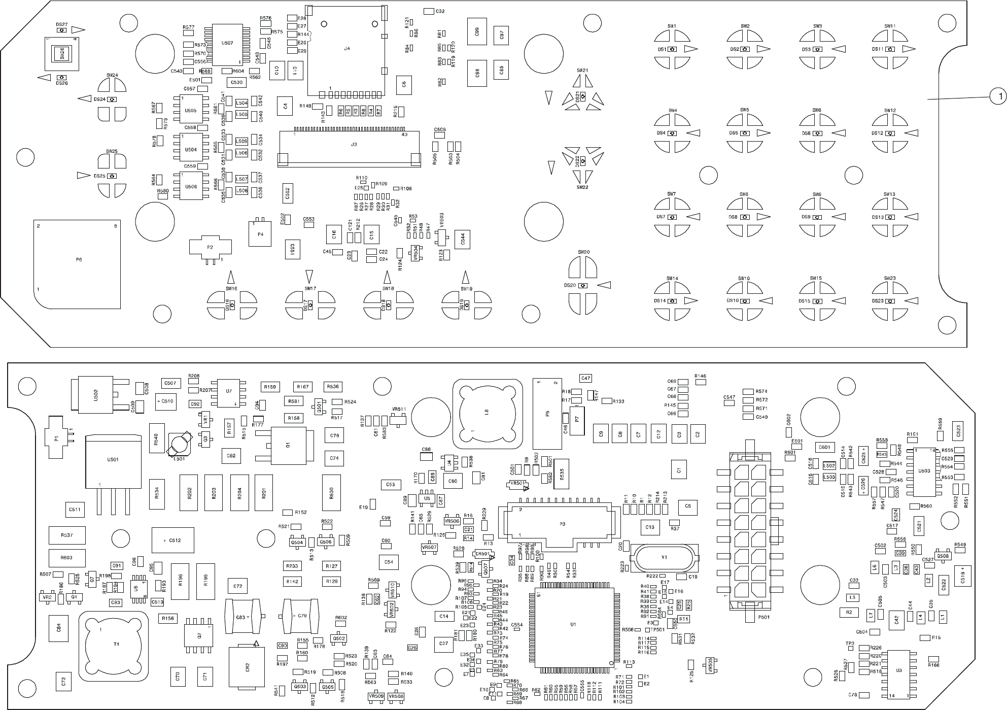
MM-E 2072-09333-00
COMPONENT SIDE
PRINT SIDE
Figure B-6. CONTROL HEAD Module (Dash Mount Version), Identification of Components
B-91/B-92

MM-E 2072-09333-00
B-93
Section II. MICOM-Z TRUNK-MOUNT VERSION
Table B-7. Micom-Z Assembly, Trunk Version, Parts List
Ref. Des. Mfg. Catalog No.
Description Qty.
2072-90719-20 MICOM-Z ASSEMBLY, TRUNK Figure B-7
BL1 2072-95170-10 HI POWER MODULE 1.0
BL2 2072-45029-10 BLANK PANEL 1.0
BL3 2072-90832-00 LORD ASSY 1.0
BL5 4053-10013-16 WASHER, SPRING, CRS, PASSIVATED, #10 1.0
BL6 4053-00037-16 WASHER, FLAT, CRS, PASSIVATED, .219 2.0
BL7 4051-00011-16 NUT, HEX, CRS, PASSIVATED, #10-32 1.0
BL8 2089-41660-00 KNOB 1.0
BL10 4053-10012-16 WASHER, SPRING, CRS, BLACK, #8 8.0
BL12 4053-16001-00 WASHER, SPRING, LOCK, M3 1.0
BL13 2072-45002-10 REAR PANEL 1.0
BL14 2072-72108-00 LABEL DISASSEMBLY 1.0
BL15 2072-72109-00 LABEL DISASSEMBLY 1.0
BL16 2072-09296-00 CABLE COAX, LORD-H.P PA 2.0
BL18 2072-90160-00 CABLE, FLAT, TO CHASSIS 1.0
BL19 2072-34007-00 CABLE, FLAT, STRIP, GPS 1.0
BL20 2072-90890-00 GPS ANTENNA TRANSITION 1.0
BL21 2072-90900-10 GPS CARD 1.0
BL22 4052-12019-88 SCREW, PH PHIL CRES, M 3X 9.0
BL23 2072-45011-00 BOX, MICOM-Z 1.0
BL24 4053-15002-00 WASHER, FLAT 1.0
BL25 2201-63202-03 HEATSINK COMPOUND, DC340 .200
BL26 2072-45041-00 LOCK PAD 2.0
BL27 4052-60248-88 SCREW, PH PHIL CRES, M 3X 1.0
BL28 2072-93405-00 INTERNAL CABLE 1.0
BL30 4052-60247-88 SCREW, CAP SOCK CRES, M 4 8.0
BL31 2072-56022-00 SPACER FOR CONNECTOR SUB-D 4.0
BL32 4052-30011-16 SCREW, #10-32X3/4 1.0
BL33 2072-45042-00 PLUG COVER, D-TYPE, 9 PIN 1.0
BL34 2072-45031-00 SCREW, M3X4, FH, BLACK 8.0
BL35 2072-45013-00 COVER 1.0
BL36 2072-09295-00 CABLE, FLAT, LORD-H.P 1.0
BL37 2072-90831-00 FRONT PANEL ASSY, TRUNK 1.0
BL38 2072-95212-00 MODULE INTERCONNECTION 1.0
BL39 2072-44015-00 BUSHING FOR TUNER 1.0
BL40 2072-33019-00 INSULATOR TO-220 CHAS, 1480075 1.0
BL41 4053-00068-16 WASHER, FLAT, CRS, PASSIVATED, .143 1.0
BL42 2072-09727-00 CABLE PANEL RADIO 16 1.0
BL44 4052-60246-88 SCREW, PH PHIL CRES, M 3X 3.0
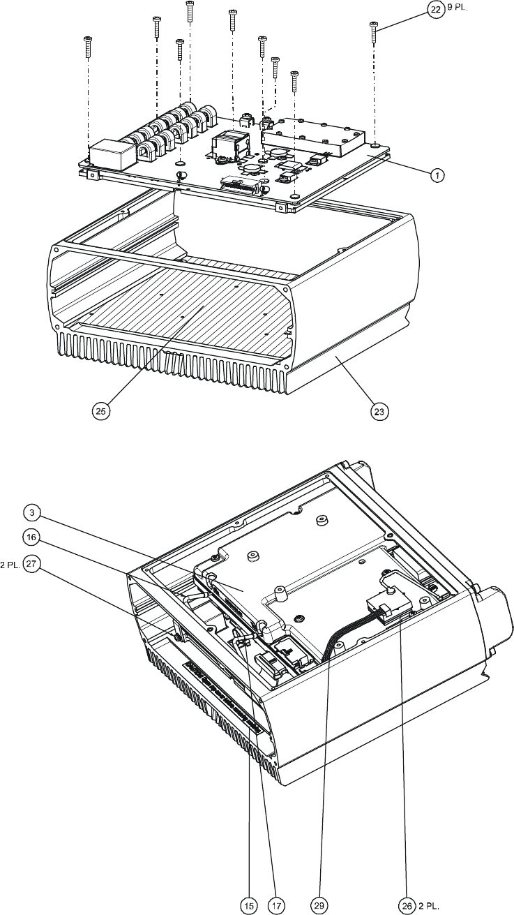
MM-E 2072-09333-00
B-94
Figure B-7.A. Micom-Z Assembly, Trunk Version (Sheet 1 of 2)
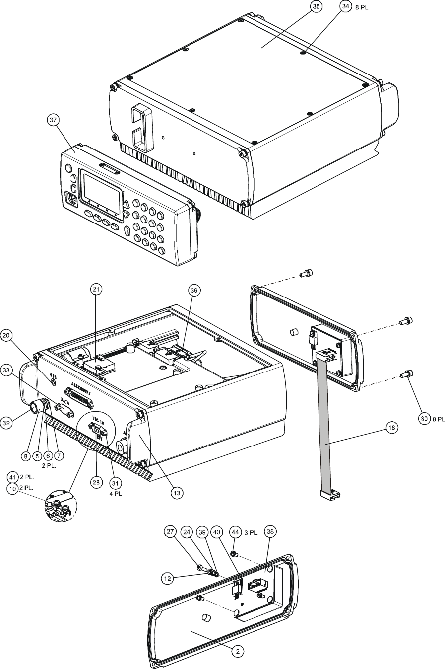
MM-E 2072-09333-00
B-95
Figure B-7.B. Micom-Z Assembly, Trunk Version (Sheet 2 of 2)
MM-E 2072-09333-00
B-96
Table B-8. LORD Assembly, Parts List
The LORD assembly used in the Micom-Z trunk version is identical to the LORD assembly used in
the Micom-Z dash version.
See page B-4 to page B-58.
MM-E 2072-09333-00
B-97
Table B-9. HI POWER Module, Parts List
The HI POWER module used in the Micom-Z trunk version is identical to the HI POWER module
used in the Micom-Z dash version.
See page B-59 to page B-78.
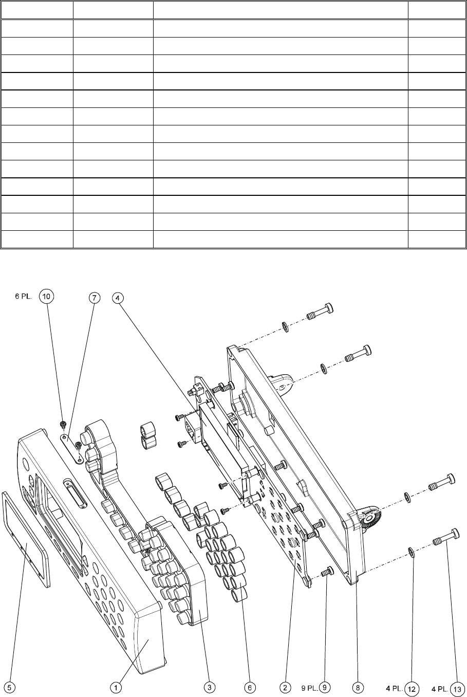
MM-E 2072-09333-00
B-98
Table B-10. Trunk Front Panel, Control Head Assembly, Parts List
Ref. Des. Mfg. Catalog No.
Description Qty.
2072-90831-00 FRONT PANEL TRUNK ASSY Figure B-8
BL1 2072-45015-10 FRONT PANEL 1.0
BL2 2072-95211-10 FRONT PANEL MODULE TRUNK 1.0
BL3 2072-45004-00 KEYPAD 1.0
BL4 2072-90115-00 DISPLAY ASSY 1.0
BL5 2072-45007-00 WINDOW LC 1.0
BL6 2072-45036-00 INSERT 1.0
BL7 2072-45020-00 PLUG 1.0
BL8 2072-45027-10 REAR PANEL 1.0
BL9 4052-15003-00 SCREW, CROSS RECESSED, PAN HEAD 9.0
BL10 2072-45030-00 SCREW, M2X6 PH BLACK 6.0
BL12 4053-10012-15 WASHER, SPRING, CRS, BLACK, #8 4.0
BL13 2072-48180-00 SCREW, CAPTIVE FOR CHASSIS 4.0
Figure B-8. Trunk Front Panel, Control Head Assembly

MM-E 2072-09333-00
B-99
Table B-11. CONTROL HEAD Module (Trunk Mount Version), Parts List
Ref. Des. Mfg. Catalog No.
Description Qty.
2072-95211-10 FRONT PANEL MODULE TRUNK Figure B-9
BL1 2072-32211-00 FRONT PANEL PCB 1.0
BL2 2072-45003-00 STUD FOR MICOM-Z 4.0
C1 4017-20153-00 CAPACITOR, CHIP, CERAMIC, 2.2UF, 25V 1.0
C2 4017-20153-00 CAPACITOR, CHIP, CERAMIC, 2.2UF, 25V 1.0
C3 4017-20153-00 CAPACITOR, CHIP, CERAMIC, 2.2UF, 25V 1.0
C4 4017-20153-00 CAPACITOR, CHIP, CERAMIC, 2.2UF, 25V 1.0
C5 4017-20153-00 CAPACITOR, CHIP, CERAMIC, 2.2UF, 25V 1.0
C6 4017-20153-00 CAPACITOR, CHIP, CERAMIC, 2.2UF, 25V 1.0
C7 4017-20153-00 CAPACITOR, CHIP, CERAMIC, 2.2UF, 25V 1.0
C8 4017-20153-00 CAPACITOR, CHIP, CERAMIC, 2.2UF, 25V 1.0
C9 4017-20153-00 CAPACITOR, CHIP, CERAMIC, 2.2UF, 25V 1.0
C10 4017-20153-00 CAPACITOR, CHIP, CERAMIC, 2.2UF, 25V 1.0
C11 4017-20153-00 CAPACITOR, CHIP, CERAMIC, 2.2UF, 25V 1.0
C12 4017-20153-00 CAPACITOR, CHIP, CERAMIC, 2.2UF, 25V 1.0
C13 4017-20153-00 CAPACITOR, CHIP, CERAMIC, 2.2UF, 25V 1.0
C14 4017-20109-25 CAPACITOR, CHIP, X7R, 10UF 1.0
C15 4017-20192-00 CAPACITOR, 1210, X7R, 4.7UF, 50V 1.0
C16 4017-20192-00 CAPACITOR, 1210, X7R, 4.7UF, 50V 1.0
C19 4017-25265-10 CAPACITOR, CHIP, NP0, 33PF, 1% 1.0
C20 4017-25265-10 CAPACITOR, CHIP, NP0, 33PF, 1% 1.0
C21 4017-25282-00 CAPACITOR, CHIP, CG, 1NF, 5% 1.0
C22 4017-20284-00 CAPACITOR, CHIP, CERAMIC, 100NF, 16V 1.0
C23 4017-20284-00 CAPACITOR, CHIP, CERAMIC, 100NF, 16V 1.0
C24 4017-20284-00 CAPACITOR, CHIP, CERAMIC, 100NF, 16V 1.0
C25 4017-20284-00 CAPACITOR, CHIP, CERAMIC, 100NF, 16V 1.0
C26 4017-20284-00 CAPACITOR, CHIP, CERAMIC, 100NF, 16V 1.0
C27 4017-20192-00 CAPACITOR, 1210, X7R, 4.7UF, 50V 1.0
C32 4017-20284-00 CAPACITOR, CHIP, CERAMIC, 100NF, 16V 1.0
C33 4017-25282-00 CAPACITOR, CHIP, CG, 1NF, 5% 1.0
C35 4017-25282-00 CAPACITOR, CHIP, CG, 1NF, 5% 1.0
C36 4017-25282-00 CAPACITOR, CHIP, CG, 1NF, 5% 1.0
C39 4017-25282-00 CAPACITOR, CHIP, CG, 1NF, 5% 1.0
C42 4017-20192-00 CAPACITOR, 1210, X7R, 4.7UF, 50V 1.0
C43 4017-25282-00 CAPACITOR, CHIP, CG, 1NF, 5% 1.0
C44 4017-20284-00 CAPACITOR, CHIP, CERAMIC, 100NF, 16V 1.0
C45 4017-20284-00 CAPACITOR, CHIP, CERAMIC, 100NF, 16V 1.0
C46 4017-20284-00 CAPACITOR, CHIP, CERAMIC, 100NF, 16V 1.0
C47 4017-20161-00 CAPACITOR, CHIP, X7R, 1UF, 10V 1.0
C53 4017-20109-25 CAPACITOR, CHIP, X7R, 10UF 1.0

MM-E 2072-09333-00
B-100
Table B-11. CONTROL HEAD Module (Trunk Mount Version), Parts List (Cont’d)
Ref. Des. Mfg. Catalog No.
Description Qty.
C54 4017-20192-00 CAPACITOR, 1210, X7R, 4.7UF, 50V 1.0
C59 4017-20284-00 CAPACITOR, CHIP, CERAMIC, 100NF, 16V 1.0
C60 4017-20284-00 CAPACITOR, CHIP, CERAMIC, 100NF, 16V 1.0
C61 4017-25271-00 CAPACITOR, CHIP, CG, 100PF, 5% 1.0
C62 4017-25271-00 CAPACITOR, CHIP, CG, 100PF, 5% 1.0
C63 4017-25271-00 CAPACITOR, CHIP, CG, 100PF, 5% 1.0
C64 4017-25271-00 CAPACITOR, CHIP, CG, 100PF, 5% 1.0
C65 4017-25271-00 CAPACITOR, CHIP, CG, 100PF, 5% 1.0
C66 4017-25263-10 CAPACITOR, CHIP, NP0, 22PF, 1% 1.0
C67 4017-25263-10 CAPACITOR, CHIP, NP0, 22PF, 1% 1.0
C68 4017-25263-10 CAPACITOR, CHIP, NP0, 22PF, 1% 1.0
C69 4017-25263-10 CAPACITOR, CHIP, NP0, 22PF, 1% 1.0
C70 4017-20192-00 CAPACITOR, 1210, X7R, 4.7UF, 50V 1.0
C71 4017-20192-00 CAPACITOR, 1210, X7R, 4.7UF, 50V 1.0
C72 4017-20192-00 CAPACITOR, 1210, X7R, 4.7UF, 50V 1.0
C73 4017-20192-00 CAPACITOR, 1210, X7R, 4.7UF, 50V 1.0
C74 4017-20192-00 CAPACITOR, 1210, X7R, 4.7UF, 50V 1.0
C76 4017-20192-00 CAPACITOR, 1210, X7R, 4.7UF, 50V 1.0
C78 4017-20284-00 CAPACITOR, CHIP, CERAMIC, 100NF, 16V 1.0
C79 4017-80304-00 CAPACITOR, 47UF, 35V 1.0
C80 4017-20191-00 CAPACITOR, 1210, X7R, 1UF, 100V 1.0
C81 4017-20165-00 CAPACITOR, CHIP, CERAMIC, 100NF, 50V 1.0
C82 4017-20191-00 CAPACITOR, 1210, X7R, 1UF, 100V 1.0
C83 4017-80304-00 CAPACITOR, 47UF, 35V 1.0
C84 2089-17202-00 CAPACITOR, 1812, X7R, 15UF, 25V 1.0
C85 4017-20192-00 CAPACITOR, 1210, X7R, 4.7UF, 50V 1.0
C86 4017-20165-00 CAPACITOR, CHIP, CERAMIC, 100NF, 50V 1.0
C87 4017-20165-00 CAPACITOR, CHIP, CERAMIC, 100NF, 50V 1.0
C88 4017-20165-00 CAPACITOR, CHIP, CERAMIC, 100NF, 50V 1.0
C89 4017-20165-00 CAPACITOR, CHIP, CERAMIC, 100NF, 50V 1.0
C90 4017-25286-00 CAPACITOR, CHIP, C0G, 100PF, 1% 1.0
C91 4017-20165-00 CAPACITOR, CHIP, CERAMIC, 100NF, 50V 1.0
C92 4017-20165-00 CAPACITOR, CHIP, CERAMIC, 100NF, 50V 1.0
C93 4017-20165-00 CAPACITOR, CHIP, CERAMIC, 100NF, 50V 1.0
C94 4017-25275-00 CAPACITOR, CHIP, CG, 220PF, 5% 1.0
C95 4017-20165-00 CAPACITOR, CHIP, CERAMIC, 100NF, 50V 1.0
C96 4017-25263-10 CAPACITOR, CHIP, NP0, 22PF, 1% 1.0
C97 4017-20192-00 CAPACITOR, 1210, X7R, 4.7UF, 50V 1.0
C98 2089-17202-00 CAPACITOR, 1812, X7R, 15UF, 25V 1.0
C99 2089-17202-00 CAPACITOR, 1812, X7R, 15UF, 25V 1.0

MM-E 2072-09333-00
B-101
Table B-11. CONTROL HEAD Module (Trunk Mount Version), Parts List (Cont’d)
Ref. Des. Mfg. Catalog No.
Description Qty.
C121 4017-20284-00 CAPACITOR, CHIP, CERAMIC, 100NF, 16V 1.0
C501 4017-25282-00 CAPACITOR, CHIP, CG, 1NF, 5% 1.0
C502 4017-25274-00 CAPACITOR, 0603, NP0, 180PF, 50V 1.0
C503 4017-25274-00 CAPACITOR, 0603, NP0, 180PF, 50V 1.0
C504 4017-25274-00 CAPACITOR, 0603, NP0, 180PF, 50V 1.0
C505 4017-25274-00 CAPACITOR, 0603, NP0, 180PF, 50V 1.0
C506 4017-20284-00 CAPACITOR, CHIP, CERAMIC, 100NF, 16V 1.0
C507 4017-20109-25 CAPACITOR, CHIP, X7R, 10UF 1.0
C508 4017-20151-00 CAPACITOR, CHIP, X7R, 100NF, 25V 1.0
C509 4017-20151-00 CAPACITOR, CHIP, X7R, 100NF, 25V 1.0
C510 4017-80126-02 CAPACITOR, CHIP, TANTALUM, 15UF, 16V 1.0
C511 4017-20191-00 CAPACITOR, 1210, X7R, 1UF, 100V 1.0
C512 4017-80308-00 CAPACITOR, 22UF, 35V 1.0
C513 4017-20165-00 CAPACITOR, CHIP, CERAMIC, 100NF, 50V 1.0
C514 4017-25282-00 CAPACITOR, CHIP, CG, 1NF, 5% 1.0
C515 4017-25282-00 CAPACITOR, CHIP, CG, 1NF, 5% 1.0
C516 4017-25282-00 CAPACITOR, CHIP, CG, 1NF, 5% 1.0
C517 4017-25282-00 CAPACITOR, CHIP, CG, 1NF, 5% 1.0
C518 4017-25282-00 CAPACITOR, CHIP, CG, 1NF, 5% 1.0
C519 4017-80127-02 CAPACITOR, CHIP, TANTALUM, 33UF, 10V 1.0
C520 4017-25277-00 CAPACITOR, CHIP, CG, 330PF, 5% 1.0
C521 4017-20109-25 CAPACITOR, CHIP, X7R, 10UF 1.0
C522 4017-20109-25 CAPACITOR, CHIP, X7R, 10UF 1.0
C523 4017-20109-25 CAPACITOR, CHIP, X7R, 10UF 1.0
C524 4017-20201-00 CAPACITOR, CHIP, X7R, 470NF, 16V 1.0
C525 4017-80102-02 CAPACITOR, CHIP, TANTALUM, 4.7UF, 10V 1.0
C526 4017-80102-02 CAPACITOR, CHIP, TANTALUM, 4.7UF, 10V 1.0
C527 4017-20284-00 CAPACITOR, CHIP, CERAMIC, 100NF, 16V 1.0
C528 4017-20284-00 CAPACITOR, CHIP, CERAMIC, 100NF, 16V 1.0
C529 4017-20284-00 CAPACITOR, CHIP, CERAMIC, 100NF, 16V 1.0
C530 4017-20109-25 CAPACITOR, CHIP, X7R, 10UF 1.0
C531 4017-25274-00 CAPACITOR, 0603, NP0, 180PF, 50V 1.0
C532 4017-25274-00 CAPACITOR, 0603, NP0, 180PF, 50V 1.0
C533 4017-25274-00 CAPACITOR, 0603, NP0, 180PF, 50V 1.0
C534 4017-25274-00 CAPACITOR, 0603, NP0, 180PF, 50V 1.0
C535 4017-25274-00 CAPACITOR, 0603, NP0, 180PF, 50V 1.0
C536 4017-25274-00 CAPACITOR, 0603, NP0, 180PF, 50V 1.0
C537 4017-25274-00 CAPACITOR, 0603, NP0, 180PF, 50V 1.0
C538 4017-25274-00 CAPACITOR, 0603, NP0, 180PF, 50V 1.0
C539 4017-25274-00 CAPACITOR, 0603, NP0, 180PF, 50V 1.0

MM-E 2072-09333-00
B-102
Table B-11. CONTROL HEAD Module (Trunk Mount Version), Parts List (Cont’d)
Ref. Des. Mfg. Catalog No.
Description Qty.
C540 4017-25274-00 CAPACITOR, 0603, NP0, 180PF, 50V 1.0
C541 4017-25274-00 CAPACITOR, 0603, NP0, 180PF, 50V 1.0
C542 4017-25274-00 CAPACITOR, 0603, NP0, 180PF, 50V 1.0
C543 4017-20284-00 CAPACITOR, CHIP, CERAMIC, 100NF, 16V 1.0
C544 4017-20192-00 CAPACITOR, 1210, X7R, 4.7UF, 50V 1.0
C545 4017-20578-00 CAPACITOR, CHIP, 0402, 100NF 1.0
C546 4017-20284-00 CAPACITOR, CHIP, CERAMIC, 100NF, 16V 1.0
C547 4017-20284-00 CAPACITOR, CHIP, CERAMIC, 100NF, 16V 1.0
C548 4017-20284-00 CAPACITOR, CHIP, CERAMIC, 100NF, 16V 1.0
C549 4017-20284-00 CAPACITOR, CHIP, CERAMIC, 100NF, 16V 1.0
C550 4017-25282-00 CAPACITOR, CHIP, CG, 1NF, 5% 1.0
C551 4017-20192-00 CAPACITOR, 1210, X7R, 4.7UF, 50V 1.0
C552 4017-20109-25 CAPACITOR, CHIP, X7R, 10UF 1.0
C553 4017-20284-00 CAPACITOR, CHIP, CERAMIC, 100NF, 16V 1.0
C554 4017-20578-00 CAPACITOR, CHIP, 0402, 100NF 1.0
C555 4017-20578-00 CAPACITOR, CHIP, 0402, 100NF 1.0
C556 4017-20284-00 CAPACITOR, CHIP, CERAMIC, 100NF, 16V 1.0
C557 4017-20284-00 CAPACITOR, CHIP, CERAMIC, 100NF, 16V 1.0
C558 4017-20284-00 CAPACITOR, CHIP, CERAMIC, 100NF, 16V 1.0
C559 4017-20284-00 CAPACITOR, CHIP, CERAMIC, 100NF, 16V 1.0
C601 4017-20109-25 CAPACITOR, CHIP, X7R, 10UF 1.0
C602 4017-20284-00 CAPACITOR, CHIP, CERAMIC, 100NF, 16V 1.0
CR2 4021-10403-35 DIODE, RECTIFIER, SCHOTTKY, MBRS360 1.0
CR501 4021-10098-35 DIODE, SWITCHING 1.0
DS1 4021-80052-35 LED, GREEN 1.0
DS2 4021-80052-35 LED, GREEN 1.0
DS3 4021-80052-35 LED, GREEN 1.0
DS4 4021-80052-35 LED, GREEN 1.0
DS5 4021-80052-35 LED, GREEN 1.0
DS6 4021-80052-35 LED, GREEN 1.0
DS7 4021-80052-35 LED, GREEN 1.0
DS8 4021-80052-35 LED, GREEN 1.0
DS9 4021-80052-35 LED, GREEN 1.0
DS10 4021-80052-35 LED, GREEN 1.0
DS11 4021-80052-35 LED, GREEN 1.0
DS12 4021-80052-35 LED, GREEN 1.0
DS13 4021-80052-35 LED, GREEN 1.0
DS14 4021-80052-35 LED, GREEN 1.0
DS15 4021-80052-35 LED, GREEN 1.0
DS16 4021-80052-35 LED, GREEN 1.0

MM-E 2072-09333-00
B-103
Table B-11. CONTROL HEAD Module (Trunk Mount Version), Parts List (Cont’d)
Ref. Des. Mfg. Catalog No.
Description Qty.
DS17 4021-80052-35 LED, GREEN 1.0
DS18 4021-80052-35 LED, GREEN 1.0
DS19 4021-80052-35 LED, GREEN 1.0
DS20 4021-80052-35 LED, GREEN 1.0
DS21 4021-80052-35 LED, GREEN 1.0
DS22 4021-80052-35 LED, GREEN 1.0
DS23 4021-80052-35 LED, GREEN 1.0
DS24 4021-80052-35 LED, GREEN 1.0
DS25 4021-80052-35 LED, GREEN 1.0
DS26 4021-80052-35 LED, GREEN 1.0
DS27 4021-80052-35 LED, GREEN 1.0
E19 4018-60017-00 BEAD, EMI, 60 OHM, 500mA 1.0
E20 4018-60030-00 BEAD, EMI, 75 OHM, 200mA 1.0
E26 4018-60017-00 BEAD, EMI, 60 OHM, 500mA 1.0
E27 4018-60030-00 BEAD, EMI, 75 OHM, 200mA 1.0
E28 4018-60030-00 BEAD, EMI, 75 OHM, 200mA 1.0
E29 4018-60030-00 BEAD, EMI, 75 OHM, 200mA 1.0
E501 4018-60017-00 BEAD, EMI, 60 OHM, 500mA 1.0
E502 4018-60017-00 BEAD, EMI, 60 OHM, 500mA 1.0
E601 4018-60017-00 BEAD, EMI, 60 OHM, 500mA 1.0
J3 4033-60109-00 CONNECTOR FPC/FFC, 40S 1.0
J4 4033-53021-00 SD MEMORY CARD CONNECTOR 1.0
L1 4018-12052-00 COIL, FIXED, 4.7UH 1.0
L2 4018-12052-00 COIL, FIXED, 4.7UH 1.0
L3 4018-12052-00 COIL, FIXED, 4.7UH 1.0
L4 4018-12052-00 COIL, FIXED, 4.7UH 1.0
L5 4018-12052-00 COIL, FIXED, 4.7UH 1.0
L6 4018-12052-00 COIL, FIXED, 4.7UH 1.0
L7 4018-12052-00 COIL, FIXED, 4.7UH 1.0
L8 4018-10116-00 INDUCTOR, 33UH 1.0
L501 4018-10202-00 INDUCTOR, 10UH 1.0
L502 4018-12052-00 COIL, FIXED, 4.7UH 1.0
L503 4018-12052-00 COIL, FIXED, 4.7UH 1.0
L504 4018-12052-00 COIL, FIXED, 4.7UH 1.0
L505 4018-12052-00 COIL, FIXED, 4.7UH 1.0
L506 4018-12052-00 COIL, FIXED, 4.7UH 1.0
L507 4018-12052-00 COIL, FIXED, 4.7UH 1.0
L508 4018-12052-00 COIL, FIXED, 4.7UH 1.0
L509 4018-12052-00 COIL, FIXED, 4.7UH 1.0
P2 4033-51109-01 CONNECTOR, 2 PIN, 1.25mm 1.0

MM-E 2072-09333-00
B-104
Table B-11. CONTROL HEAD Module (Trunk Mount Version), Parts List (Cont’d)
Ref. Des. Mfg. Catalog No.
Description Qty.
P4 4033-51007-01 HEADER, 2 PIN 1.0
P5 4033-50225-01 STRIP, DOUBLE ROW, 5 PIN 1.0
P6 2072-33325-00 CONNECTOR, MIC 1.0
P7 4033-50212-01 STRIP, SINGLE ROW, 2 PIN 1.0
P501 4033-51315-00 CONNECTOR, HEADER, DUAL ROW, 16 PIN 1.0
Q1 4021-00183-35 MOSFET, P-CHANNEL 1.0
Q2 4021-00299-35 MOSFET, N-CHANNEL 1.0
Q3 4021-00202-35 TRANSISTOR, NPN, MMBT2222A 1.0
Q4 4021-00202-35 TRANSISTOR, NPN, MMBT2222A 1.0
Q7 4021-00415-35 FET 1.0
Q501 4021-00415-35 FET 1.0
Q502 4021-00415-35 FET 1.0
Q503 4021-00341-35 TRANSISTOR, PNP 1.0
Q504 4021-00341-35 TRANSISTOR, PNP 1.0
Q505 4021-00415-35 FET 1.0
Q506 4021-00415-35 FET 1.0
Q507 4021-00415-35 FET 1.0
Q508 4021-00202-35 TRANSISTOR, NPN, MMBT2222A 1.0
R1 4016-20000-50 RESISTOR, CHIP, 0603, JUMPER 1.0
R2 4016-11009-10 RESISTOR, CHIP, 10.0K, 1%, 1/8W 1.0
R3 4016-21002-10 RESISTOR, 10.0K, 1%, 1/16W 1.0
R4 4016-21002-10 RESISTOR, 10.0K, 1%, 1/16W 1.0
R5 4016-21002-10 RESISTOR, 10.0K, 1%, 1/16W 1.0
R9 4016-22210-10 RESISTOR, 221, 1%, 1/16W 1.0
R12 4016-21004-10 RESISTOR, 1.0M, 1%, 1/16W 1.0
R13 4016-21009-10 RESISTOR, CHIP, 0603, 10, 1% 1.0
R14 4016-21009-10 RESISTOR, CHIP, 0603, 10, 1% 1.0
R15 4016-24751-10 RESISTOR, 4.75K, 1%, 1/16W 1.0
R16 4016-24751-10 RESISTOR, 4.75K, 1%, 1/16W 1.0
R17 4016-21001-10 RESISTOR, 1.00K, 1%, 1/16W 1.0
R18 4016-21003-10 RESISTOR, 100K, 1%, 1/16W 1.0
R19 4016-52219-10 RESISTOR, CHIP, 0402, 22.1 1.0
R20 4016-52219-10 RESISTOR, CHIP, 0402, 22.1 1.0
R21 4016-52219-10 RESISTOR, CHIP, 0402, 22.1 1.0
R22 4016-52219-10 RESISTOR, CHIP, 0402, 22.1 1.0
R23 4016-52219-10 RESISTOR, CHIP, 0402, 22.1 1.0
R24 4016-52219-10 RESISTOR, CHIP, 0402, 22.1 1.0
R25 4016-21212-10 RESISTOR, 12.1K, 1%, 1/16W 1.0
R26 4016-52219-10 RESISTOR, CHIP, 0402, 22.1 1.0
R27 4016-52219-10 RESISTOR, CHIP, 0402, 22.1 1.0

MM-E 2072-09333-00
B-105
Table B-11. CONTROL HEAD Module (Trunk Mount Version), Parts List (Cont’d)
Ref. Des. Mfg. Catalog No.
Description Qty.
R28 4016-52219-10 RESISTOR, CHIP, 0402, 22.1 1.0
R29 4016-52219-10 RESISTOR, CHIP, 0402, 22.1 1.0
R30 4016-52219-10 RESISTOR, CHIP, 0402, 22.1 1.0
R31 4016-52219-10 RESISTOR, CHIP, 0402, 22.1 1.0
R32 4016-52219-10 RESISTOR, CHIP, 0402, 22.1 1.0
R33 4016-52219-10 RESISTOR, CHIP, 0402, 22.1 1.0
R34 4016-52219-10 RESISTOR, CHIP, 0402, 22.1 1.0
R35 4016-52219-10 RESISTOR, CHIP, 0402, 22.1 1.0
R36 4016-52219-10 RESISTOR, CHIP, 0402, 22.1 1.0
R37 4016-21004-10 RESISTOR, 1.0M, 1%, 1/16W 1.0
R38 4016-52219-10 RESISTOR, CHIP, 0402, 22.1 1.0
R39 4016-52219-10 RESISTOR, CHIP, 0402, 22.1 1.0
R40 4016-52219-10 RESISTOR, CHIP, 0402, 22.1 1.0
R41 4016-52219-10 RESISTOR, CHIP, 0402, 22.1 1.0
R42 4016-52219-10 RESISTOR, CHIP, 0402, 22.1 1.0
R43 4016-52219-10 RESISTOR, CHIP, 0402, 22.1 1.0
R44 4016-52219-10 RESISTOR, CHIP, 0402, 22.1 1.0
R45 4016-52219-10 RESISTOR, CHIP, 0402, 22.1 1.0
R46 4016-52219-10 RESISTOR, CHIP, 0402, 22.1 1.0
R47 4016-52219-10 RESISTOR, CHIP, 0402, 22.1 1.0
R48 4016-52219-10 RESISTOR, CHIP, 0402, 22.1 1.0
R49 4016-52219-10 RESISTOR, CHIP, 0402, 22.1 1.0
R50 4016-52219-10 RESISTOR, CHIP, 0402, 22.1 1.0
R51 4016-52219-10 RESISTOR, CHIP, 0402, 22.1 1.0
R52 4016-52219-10 RESISTOR, CHIP, 0402, 22.1 1.0
R53 4016-52219-10 RESISTOR, CHIP, 0402, 22.1 1.0
R54 4016-52219-10 RESISTOR, CHIP, 0402, 22.1 1.0
R55 4016-52219-10 RESISTOR, CHIP, 0402, 22.1 1.0
R56 4016-52219-10 RESISTOR, CHIP, 0402, 22.1 1.0
R57 4016-52219-10 RESISTOR, CHIP, 0402, 22.1 1.0
R58 4016-52219-10 RESISTOR, CHIP, 0402, 22.1 1.0
R59 4016-52219-10 RESISTOR, CHIP, 0402, 22.1 1.0
R60 4016-52219-10 RESISTOR, CHIP, 0402, 22.1 1.0
R61 4016-52219-10 RESISTOR, CHIP, 0402, 22.1 1.0
R62 4016-52219-10 RESISTOR, CHIP, 0402, 22.1 1.0
R63 4016-52219-10 RESISTOR, CHIP, 0402, 22.1 1.0
R64 4016-52219-10 RESISTOR, CHIP, 0402, 22.1 1.0
R65 4016-52219-10 RESISTOR, CHIP, 0402, 22.1 1.0
R66 4016-52219-10 RESISTOR, CHIP, 0402, 22.1 1.0
R67 4016-52219-10 RESISTOR, CHIP, 0402, 22.1 1.0

MM-E 2072-09333-00
B-106
Table B-11. CONTROL HEAD Module (Trunk Mount Version), Parts List (Cont’d)
Ref. Des. Mfg. Catalog No.
Description Qty.
R68 4016-52219-10 RESISTOR, CHIP, 0402, 22.1 1.0
R69 4016-52219-10 RESISTOR, CHIP, 0402, 22.1 1.0
R70 4016-52219-10 RESISTOR, CHIP, 0402, 22.1 1.0
R71 4016-52219-10 RESISTOR, CHIP, 0402, 22.1 1.0
R72 4016-52219-10 RESISTOR, CHIP, 0402, 22.1 1.0
R73 4016-52219-10 RESISTOR, CHIP, 0402, 22.1 1.0
R74 4016-52219-10 RESISTOR, CHIP, 0402, 22.1 1.0
R75 4016-52219-10 RESISTOR, CHIP, 0402, 22.1 1.0
R76 4016-52219-10 RESISTOR, CHIP, 0402, 22.1 1.0
R77 4016-52219-10 RESISTOR, CHIP, 0402, 22.1 1.0
R78 4016-52219-10 RESISTOR, CHIP, 0402, 22.1 1.0
R79 4016-52219-10 RESISTOR, CHIP, 0402, 22.1 1.0
R80 4016-52219-10 RESISTOR, CHIP, 0402, 22.1 1.0
R81 4016-50000-50 RESISTOR, CHIP, 0402, JUMPER 1.0
R82 4016-50000-50 RESISTOR, CHIP, 0402, JUMPER 1.0
R83 4016-50000-50 RESISTOR, CHIP, 0402, JUMPER 1.0
R84 4016-50000-50 RESISTOR, CHIP, 0402, JUMPER 1.0
R85 4016-50000-50 RESISTOR, CHIP, 0402, JUMPER 1.0
R86 4016-50000-50 RESISTOR, CHIP, 0402, JUMPER 1.0
R87 4016-51002-10 RESISTOR, CHIP, MF, 10K, 0.06W 1.0
R88 4016-52219-10 RESISTOR, CHIP, 0402, 22.1 1.0
R89 4016-52219-10 RESISTOR, CHIP, 0402, 22.1 1.0
R90 4016-52219-10 RESISTOR, CHIP, 0402, 22.1 1.0
R91 4016-52219-10 RESISTOR, CHIP, 0402, 22.1 1.0
R92 4016-52219-10 RESISTOR, CHIP, 0402, 22.1 1.0
R93 4016-51002-10 RESISTOR, CHIP, MF, 10K, 0.06W 1.0
R94 4016-51002-10 RESISTOR, CHIP, MF, 10K, 0.06W 1.0
R95 4016-51002-10 RESISTOR, CHIP, MF, 10K, 0.06W 1.0
R96 4016-51002-10 RESISTOR, CHIP, MF, 10K, 0.06W 1.0
R97 4016-51002-10 RESISTOR, CHIP, MF, 10K, 0.06W 1.0
R98 4016-51002-10 RESISTOR, CHIP, MF, 10K, 0.06W 1.0
R99 4016-51002-10 RESISTOR, CHIP, MF, 10K, 0.06W 1.0
R100 4016-51002-10 RESISTOR, CHIP, MF, 10K, 0.06W 1.0
R101 4016-51002-10 RESISTOR, CHIP, MF, 10K, 0.06W 1.0
R102 4016-51002-10 RESISTOR, CHIP, MF, 10K, 0.06W 1.0
R103 4016-51002-10 RESISTOR, CHIP, MF, 10K, 0.06W 1.0
R104 4016-51002-10 RESISTOR, CHIP, MF, 10K, 0.06W 1.0
R105 4016-51002-10 RESISTOR, CHIP, MF, 10K, 0.06W 1.0
R106 4016-51002-10 RESISTOR, CHIP, MF, 10K, 0.06W 1.0
R107 4016-51002-10 RESISTOR, CHIP, MF, 10K, 0.06W 1.0

MM-E 2072-09333-00
B-107
Table B-11. CONTROL HEAD Module (Trunk Mount Version), Parts List (Cont’d)
Ref. Des. Mfg. Catalog No.
Description Qty.
R108 4016-51002-10 RESISTOR, CHIP, MF, 10K, 0.06W 1.0
R109 4016-51002-10 RESISTOR, CHIP, MF, 10K, 0.06W 1.0
R110 4016-51002-10 RESISTOR, CHIP, MF, 10K, 0.06W 1.0
R111 4016-51002-10 RESISTOR, CHIP, MF, 10K, 0.06W 1.0
R112 4016-51002-10 RESISTOR, CHIP, MF, 10K, 0.06W 1.0
R113 4016-51002-10 RESISTOR, CHIP, MF, 10K, 0.06W 1.0
R114 4016-52219-10 RESISTOR, CHIP, 0402, 22.1 1.0
R115 4016-52219-10 RESISTOR, CHIP, 0402, 22.1 1.0
R116 4016-52219-10 RESISTOR, CHIP, 0402, 22.1 1.0
R117 4016-52219-10 RESISTOR, CHIP, 0402, 22.1 1.0
R118 4016-51002-10 RESISTOR, CHIP, MF, 10K, 0.06W 1.0
R119 4016-51002-10 RESISTOR, CHIP, MF, 10K, 0.06W 1.0
R120 4016-51002-10 RESISTOR, CHIP, MF, 10K, 0.06W 1.0
R121 4016-51002-10 RESISTOR, CHIP, MF, 10K, 0.06W 1.0
R122 4016-21500-10 RESISTOR, CHIP, MF, 150E, 0.063W 1.0
R123 4016-21500-10 RESISTOR, CHIP, MF, 150E, 0.063W 1.0
R124 4016-21500-10 RESISTOR, CHIP, MF, 150E, 0.063W 1.0
R125 4016-21500-10 RESISTOR, CHIP, MF, 150E, 0.063W 1.0
R126 4016-21500-10 RESISTOR, CHIP, MF, 150E, 0.063W 1.0
R127 4016-11500-10 RESISTOR, CHIP, 150, 1%, 1/8W 1.0
R128 4016-11500-10 RESISTOR, CHIP, 150, 1%, 1/8W 1.0
R133 4016-21002-10 RESISTOR, 10.0K, 1%, 1/16W 1.0
R137 4016-22002-10 RESISTOR, 20.0K, 1%, 1/16W 1.0
R138 4016-22002-10 RESISTOR, 20.0K, 1%, 1/16W 1.0
R139 4016-22002-10 RESISTOR, 20.0K, 1%, 1/16W 1.0
R140 4016-22002-10 RESISTOR, 20.0K, 1%, 1/16W 1.0
R141 4016-22002-10 RESISTOR, 20.0K, 1%, 1/16W 1.0
R142 4016-11500-10 RESISTOR, CHIP, 150, 1%, 1/8W 1.0
R143 4016-25112-10 RESISTOR, 51.1K, 1%, 1/16W 1.0
R144 4016-25112-10 RESISTOR, 51.1K, 1%, 1/16W 1.0
R145 4016-25112-10 RESISTOR, 51.1K, 1%, 1/16W 1.0
R146 4016-25112-10 RESISTOR, 51.1K, 1%, 1/16W 1.0
R151 4016-21000-10 RESISTOR, 100, 1%, 1/16W 1.0
R152 4016-20000-50 RESISTOR, CHIP, 0603, JUMPER 1.0
R155 4016-20000-50 RESISTOR, CHIP, 0603, JUMPER 1.0
R156 4016-10519-50 RESISTOR, CHIP, 5.1, 5%, 1/8W 1.0
R157 4016-13011-10 RESISTOR, CHIP, 3.01K, 1%, 1/8W 1.0
R158 4016-14751-10 RESISTOR, CHIP, 4.75K, 1%, 1/8W 1.0
R159 4016-15111-10 RESISTOR, CHIP, 5.11K, 1%, 1/8W 1.0
R160 4016-25110-10 RESISTOR, 511, 1%, 1/16W 1.0

MM-E 2072-09333-00
B-108
Table B-11. CONTROL HEAD Module (Trunk Mount Version), Parts List (Cont’d)
Ref. Des. Mfg. Catalog No.
Description Qty.
R166 4016-21009-10 RESISTOR, CHIP, 0603, 10, 1% 1.0
R167 4016-14750-10 RESISTOR, CHIP, 475, 1%, 1/8W 1.0
R170 4016-23329-10 RESISTOR, CHIP, 0603, 33.2, 1% 1.0
R177 4016-20000-50 RESISTOR, CHIP, 0603, JUMPER 1.0
R178 4016-23011-10 RESISTOR, 3.01K, 1%, 1/16W 1.0
R181 4016-20000-50 RESISTOR, CHIP, 0603, JUMPER 1.0
R186 4016-21002-10 RESISTOR, 10.0K, 1%, 1/16W 1.0
R187 4016-21002-10 RESISTOR, 10.0K, 1%, 1/16W 1.0
R193 4016-24121-10 RESISTOR, 4.12K, 1%, 1/16W 1.0
R194 4016-23012-10 RESISTOR, CHIP, 0603, 30.1K, 1% 1.0
R195 4016-31900-10 RESISTOR, CHIP, 0.1, 1%, 1W 1.0
R196 4016-31900-10 RESISTOR, CHIP, 0.1, 1%, 1W 1.0
R197 4016-23162-10 RESISTOR, CHIP, 0603, 31.6K, 1% 1.0
R198 4016-24751-10 RESISTOR, 4.75K, 1%, 1/16W 1.0
R201 4016-43329-10 RESISTOR, CHIP, 33.2, 1%, 1W 1.0
R202 4016-43329-10 RESISTOR, CHIP, 33.2, 1%, 1W 1.0
R203 4016-43329-10 RESISTOR, CHIP, 33.2, 1%, 1W 1.0
R204 4016-43329-10 RESISTOR, CHIP, 33.2, 1%, 1W 1.0
R206 4016-25111-10 RESISTOR, 5.11K, 1%, 1/16W 1.0
R207 4016-25111-10 RESISTOR, 5.11K, 1%, 1/16W 1.0
R212 4016-22213-10 RESISTOR, 221K, 1%, 1/16W 1.0
R213 4016-20000-50 RESISTOR, CHIP, 0603, JUMPER 1.0
R214 4016-20000-50 RESISTOR, CHIP, 0603, JUMPER 1.0
R215 4016-20000-50 RESISTOR, CHIP, 0603, JUMPER 1.0
R220 4016-21009-10 RESISTOR, CHIP, 0603, 10, 1% 1.0
R221 4016-21009-10 RESISTOR, CHIP, 0603, 10, 1% 1.0
R222 4016-52219-10 RESISTOR, CHIP, 0402, 22.1 1.0
R223 4016-52219-10 RESISTOR, CHIP, 0402, 22.1 1.0
R226 4016-21009-10 RESISTOR, CHIP, 0603, 10, 1% 1.0
R229 4016-24751-10 RESISTOR, 4.75K, 1%, 1/16W 1.0
R233 4016-14999-10 RESISTOR, CHIP, 49.9, 1%, 1/8W 1.0
R501 4016-20000-50 RESISTOR, CHIP, 0603, JUMPER 1.0
R505 4016-21002-10 RESISTOR, 10.0K, 1%, 1/16W 1.0
R507 4016-21000-10 RESISTOR, 100, 1%, 1/16W 1.0
R508 4016-21000-10 RESISTOR, 100, 1%, 1/16W 1.0
R509 4016-21000-10 RESISTOR, 100, 1%, 1/16W 1.0
R512 4016-25110-10 RESISTOR, 511, 1%, 1/16W 1.0
R513 4016-21001-10 RESISTOR, 1.00K, 1%, 1/16W 1.0
R514 4016-21001-10 RESISTOR, 1.00K, 1%, 1/16W 1.0
R515 4016-21101-10 RESISTOR, 1.10K, 1%, 1/16W 1.0

MM-E 2072-09333-00
B-109
Table B-11. CONTROL HEAD Module (Trunk Mount Version), Parts List (Cont’d)
Ref. Des. Mfg. Catalog No.
Description Qty.
R516 4016-23011-10 RESISTOR, 3.01K, 1%, 1/16W 1.0
R517 4016-21000-10 RESISTOR, 100, 1%, 1/16W 1.0
R518 4016-21002-10 RESISTOR, 10.0K, 1%, 1/16W 1.0
R519 4016-21002-10 RESISTOR, 10.0K, 1%, 1/16W 1.0
R520 4016-21000-10 RESISTOR, 100, 1%, 1/16W 1.0
R521 4016-21002-10 RESISTOR, 10.0K, 1%, 1/16W 1.0
R522 4016-21002-10 RESISTOR, 10.0K, 1%, 1/16W 1.0
R523 4016-21002-10 RESISTOR, 10.0K, 1%, 1/16W 1.0
R524 4016-21002-10 RESISTOR, 10.0K, 1%, 1/16W 1.0
R525 4016-21002-10 RESISTOR, 10.0K, 1%, 1/16W 1.0
R527 4016-21002-10 RESISTOR, 10.0K, 1%, 1/16W 1.0
R528 4016-21002-10 RESISTOR, 10.0K, 1%, 1/16W 1.0
R529 4016-21101-10 RESISTOR, 1.10K, 1%, 1/16W 1.0
R530 4016-43329-10 RESISTOR, CHIP, 33.2, 1%, 1W 1.0
R531 4016-20000-50 RESISTOR, CHIP, 0603, JUMPER 1.0
R532 4016-20000-50 RESISTOR, CHIP, 0603, JUMPER 1.0
R533 4016-21101-10 RESISTOR, 1.10K, 1%, 1/16W 1.0
R534 4016-60000-50 RESISTOR, CHIP, 0 OHM, 1/2W 1.0
R535 4016-60000-50 RESISTOR, CHIP, 0 OHM, 1/2W 1.0
R536 4016-18251-10 RESISTOR, CHIP, 8.25K, 1%, 1/8W 1.0
R537 4016-45119-10 RESISTOR, 2512 51.1, 1%, 1W 1.0
R538 4016-24029-10 RESISTOR, CHIP, 0603, 40.2, 1% 1.0
R539 4016-23329-10 RESISTOR, CHIP, 0603, 33.2, 1% 1.0
R540 4016-62009-10 RESISTOR, CHIP, 20, 1%, 1/2W 1.0
R541 4016-28669-10 RESISTOR, CHIP, 0603, 86.6, 1% 1.0
R542 4016-21001-10 RESISTOR, 1.00K, 1%, 1/16W 1.0
R543 4016-21001-10 RESISTOR, 1.00K, 1%, 1/16W 1.0
R544 4016-21002-10 RESISTOR, 10.0K, 1%, 1/16W 1.0
R545 4016-21002-10 RESISTOR, 10.0K, 1%, 1/16W 1.0
R546 4016-21002-10 RESISTOR, 10.0K, 1%, 1/16W 1.0
R547 4016-21002-10 RESISTOR, 10.0K, 1%, 1/16W 1.0
R548 4016-21002-10 RESISTOR, 10.0K, 1%, 1/16W 1.0
R549 4016-21002-10 RESISTOR, 10.0K, 1%, 1/16W 1.0
R550 4016-21002-10 RESISTOR, 10.0K, 1%, 1/16W 1.0
R551 4016-22002-10 RESISTOR, 20.0K, 1%, 1/16W 1.0
R552 4016-22002-10 RESISTOR, 20.0K, 1%, 1/16W 1.0
R553 4016-22002-10 RESISTOR, 20.0K, 1%, 1/16W 1.0
R554 4016-22002-10 RESISTOR, 20.0K, 1%, 1/16W 1.0
R555 4016-22002-10 RESISTOR, 20.0K, 1%, 1/16W 1.0
R556 4016-25620-10 RESISTOR, CHIP, 0603, 562, 1% 1.0

MM-E 2072-09333-00
B-110
Table B-11. CONTROL HEAD Module (Trunk Mount Version), Parts List (Cont’d)
Ref. Des. Mfg. Catalog No.
Description Qty.
R557 4016-22740-10 RESISTOR, 274, 1%, 1/16W 1.0
R558 4016-22740-10 RESISTOR, 274, 1%, 1/16W 1.0
R559 4016-22741-10 RESISTOR, 2.74K, 1%, 1/16W 1.0
R560 4016-24751-10 RESISTOR, 4.75K, 1%, 1/16W 1.0
R561 4016-21001-10 RESISTOR, 1.00K, 1%, 1/16W 1.0
R562 4016-21001-10 RESISTOR, 1.00K, 1%, 1/16W 1.0
R563 4016-21101-10 RESISTOR, 1.10K, 1%, 1/16W 1.0
R564 4016-21001-10 RESISTOR, 1.00K, 1%, 1/16W 1.0
R565 4016-21001-10 RESISTOR, 1.00K, 1%, 1/16W 1.0
R566 4016-21001-10 RESISTOR, 1.00K, 1%, 1/16W 1.0
R567 4016-21001-10 RESISTOR, 1.00K, 1%, 1/16W 1.0
R568 4016-21002-10 RESISTOR, 10.0K, 1%, 1/16W 1.0
R569 4016-21101-10 RESISTOR, 1.10K, 1%, 1/16W 1.0
R574 4016-21009-10 RESISTOR, CHIP, 0603, 10, 1% 1.0
R575 4016-21009-10 RESISTOR, CHIP, 0603, 10, 1% 1.0
R576 4016-21009-10 RESISTOR, CHIP, 0603, 10, 1% 1.0
R577 4016-21009-10 RESISTOR, CHIP, 0603, 10, 1% 1.0
R578 4016-21009-10 RESISTOR, CHIP, 0603, 10, 1% 1.0
R579 4016-21009-10 RESISTOR, CHIP, 0603, 10, 1% 1.0
R580 4016-21009-10 RESISTOR, CHIP, 0603, 10, 1% 1.0
R581 4016-12671-10 RESISTOR, CHIP, 2.67K, 1%, 1/8W 1.0
R582 4016-20000-50 RESISTOR, CHIP, 0603, JUMPER 1.0
R583 4016-21101-10 RESISTOR, 1.10K, 1%, 1/16W 1.0
R584 4016-50000-50 RESISTOR, CHIP, 0402, JUMPER 1.0
R601 4016-21002-10 RESISTOR, 10.0K, 1%, 1/16W 1.0
R602 4016-25110-10 RESISTOR, 511, 1%, 1/16W 1.0
R603 4016-45119-10 RESISTOR, 2512 51.1, 1%, 1W 1.0
R604 4016-21009-10 RESISTOR, CHIP, 0603, 10, 1% 1.0
RT1 4016-91103-20 THERMISTOR, NTC 1.0
SW26 2036-31016-00 SWITCH, DPDT, LOCKING 1.0
T1 4018-10178-00 TRAFO, DUAL WINDING, SHIELDED 1.0
U1 4021-50043-64 MICROCONTROLLER, 8051 1.0
U3 4021-31132-50 SCHMITT TRIGGER, 74HC132 1.0
U4 4021-22111-54 VOLTAGE REGULATOR, 3.3V 1.0
U5 4021-22108-54 VOLTAGE REGULATOR, 3.0V 1.0
U6 4021-22020-64 PWM CONTROLLER 1.0
U7 4021-20504-54 COMPARATOR, DUAL, 2-36V 1.0
U501 4021-20045-84 VOLTAGE REGULATOR, FIXED 1.0
U502 4021-22114-50 VOLTAGE REGULATOR, FIXED 1.0
U503 4021-20170-54 OPERATIONAL AMPLIFIER, QUAD 1.0

MM-E 2072-09333-00
B-111
Table B-11. CONTROL HEAD Module (Trunk Mount Version), Parts List (Cont’d)
Ref. Des. Mfg. Catalog No.
Description Qty.
U504 4021-70098-54 LINE TRANSCEIVER, RS-485 1.0
U505 4021-70098-54 LINE TRANSCEIVER, RS-485 1.0
U506 4021-70098-54 LINE TRANSCEIVER, RS-485 1.0
U507 4021-70697-64 RS232, 2TX+2RX 1.0
VR1 4021-10471-35 ZENER, 4.3V 1.0
VR2 4021-10471-35 ZENER, 4.3V 1.0
VR501 4021-10810-35 ZENER, 3.6V 1.0
VR502 4021-10471-35 ZENER, 4.3V 1.0
VR503 4021-10471-35 ZENER, 4.3V 1.0
VR504 4021-10471-35 ZENER, 4.3V 1.0
VR505 4021-10471-35 ZENER, 4.3V 1.0
VR506 4021-10471-35 ZENER, 4.3V 1.0
VR507 4021-10471-35 ZENER, 4.3V 1.0
VR508 4021-10471-35 ZENER, 4.3V 1.0
VR509 4021-10471-35 ZENER, 4.3V 1.0
VR510 4021-10471-35 ZENER, 4.3V 1.0
VR511 4021-10471-35 ZENER, 4.3V 1.0
Y1 4022-50026-00 CRYSTAL QUARTZ, 7.3728 MHz 1.0
MM-E 2072-09333-00
B-112
Intentionally Left Blank
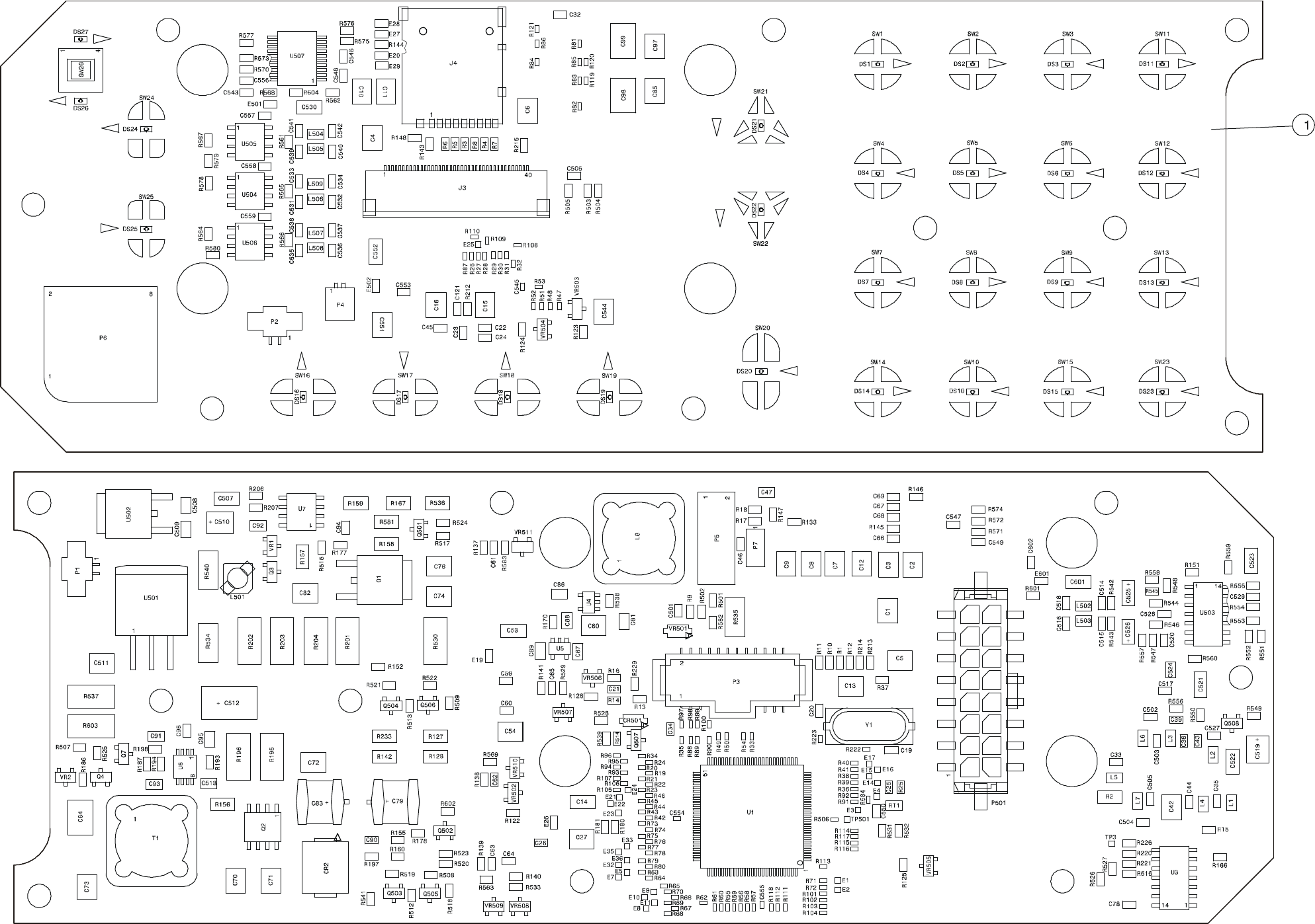
MM-E 2072-09333-00
COMPONENT SIDE
PRINT SIDE
Figure B-9. CONTROL HEAD Module (Trunk Mount Version), Identification of Components
B-113/B-114

MM-E 2072-09333-00
B-115
Table B-12. INTERCONNECTION Module, Parts List
Ref. Des. Mfg. Catalog No.
Description Qty.
2072-95212-00 INTERCONNECTION MODULE Figure B-10
BL1 2072-32212-00 INTERCONNECTION PCB 1.0
C1 2072-17821-00 CAPACITOR, CHIP, X7R, 390NF, 16V 1.0
C2 2072-17821-00 CAPACITOR, CHIP, X7R, 390NF, 16V 1.0
C3 2072-17821-00 CAPACITOR, CHIP, X7R, 390NF, 16V 1.0
C4 2072-17821-00 CAPACITOR, CHIP, X7R, 390NF, 16V 1.0
C5 2072-17821-00 CAPACITOR, CHIP, X7R, 390NF, 16V 1.0
C6 4017-25282-00 CAPACITOR, CHIP, CG, 1NF, 5% 1.0
C7 4017-25282-00 CAPACITOR, CHIP, CG, 1NF, 5% 1.0
C8 4017-25282-00 CAPACITOR, CHIP, CG, 1NF, 5% 1.0
C9 4017-25282-00 CAPACITOR, CHIP, CG, 1NF, 5% 1.0
C10 4017-25282-00 CAPACITOR, CHIP, CG, 1NF, 5% 1.0
C11 4017-25282-00 CAPACITOR, CHIP, CG, 1NF, 5% 1.0
C14 4017-25282-00 CAPACITOR, CHIP, CG, 1NF, 5% 1.0
C15 4017-25282-00 CAPACITOR, CHIP, CG, 1NF, 5% 1.0
C16 4017-25282-00 CAPACITOR, CHIP, CG, 1NF, 5% 1.0
C17 4017-25282-00 CAPACITOR, CHIP, CG, 1NF, 5% 1.0
C18 4017-25274-00 CAPACITOR, 0603, NP0, 180PF, 50V 1.0
C19 4017-25274-00 CAPACITOR, 0603, NP0, 180PF, 50V 1.0
C20 4017-25274-00 CAPACITOR, 0603, NP0, 180PF, 50V 1.0
C21 4017-25274-00 CAPACITOR, 0603, NP0, 180PF, 50V 1.0
C22 4017-25274-00 CAPACITOR, 0603, NP0, 180PF, 50V 1.0
C23 4017-25274-00 CAPACITOR, 0603, NP0, 180PF, 50V 1.0
C24 4017-25274-00 CAPACITOR, 0603, NP0, 180PF, 50V 1.0
C25 4017-25274-00 CAPACITOR, 0603, NP0, 180PF, 50V 1.0
C26 4017-25274-00 CAPACITOR, 0603, NP0, 180PF, 50V 1.0
C27 4017-25274-00 CAPACITOR, 0603, NP0, 180PF, 50V 1.0
C28 4017-25274-00 CAPACITOR, 0603, NP0, 180PF, 50V 1.0
C29 4017-25274-00 CAPACITOR, 0603, NP0, 180PF, 50V 1.0
C30 4017-20109-25 CAPACITOR, CHIP, X7R, 10UF 1.0
C31 4017-20109-25 CAPACITOR, CHIP, X7R, 10UF 1.0
C32 4017-20567-00 CAPACITOR, CHIP, X7R, 10NF, 16V 1.0
C33 4017-20284-00 CAPACITOR, CHIP, CERAMIC, 100NF, 16V 1.0
C34 4017-20284-00 CAPACITOR, CHIP, CERAMIC, 100NF, 16V 1.0
C35 4017-20284-00 CAPACITOR, CHIP, CERAMIC, 100NF, 16V 1.0
C36 4017-20151-00 CAPACITOR, CHIP, X7R, 100NF, 25V 1.0
C37 4017-20165-00 CAPACITOR, CHIP, CERAMIC, 100NF, 50V 1.0
C38 4017-20165-00 CAPACITOR, CHIP, CERAMIC, 100NF, 50V 1.0
C39 4017-25282-00 CAPACITOR, CHIP, CG, 1NF, 5% 1.0

MM-E 2072-09333-00
B-116
Table B-12. INTERCONNECTION Module, Parts List (Cont’d)
Ref. Des. Mfg. Catalog No.
Description Qty.
L1 4018-12052-00 COIL, FIXED, 4.7UH 1.0
L2 4018-12052-00 COIL, FIXED, 4.7UH 1.0
L3 4018-12052-00 COIL, FIXED, 4.7UH 1.0
L4 4018-12052-00 COIL, FIXED, 4.7UH 1.0
L5 4018-12052-00 COIL, FIXED, 4.7UH 1.0
L6 4018-12052-00 COIL, FIXED, 4.7UH 1.0
L7 4018-10016-00 COIL, CHIP, 22UH, 10% 1.0
L8 4018-10016-00 COIL, CHIP, 22UH, 10% 1.0
L9 4018-10016-00 COIL, CHIP, 22UH, 10% 1.0
L10 4018-10016-00 COIL, CHIP, 22UH, 10% 1.0
L11 4018-10016-00 COIL, CHIP, 22UH, 10% 1.0
P1 4033-51201-01 HEADER, 0.05", 24 PIN, DUAL ROW 1.0
P2 4033-51315-00 CONNECTOR, HEADER,16 PIN, DUAL ROW 1.0
Q1 2072-21060-00 TRANSISTOR, PNP, 60V 1.0
R1 4016-15620-10 RESISTOR, CHIP, 562, 1%, 1/8W 1.0
R2 4016-12610-10 RESISTOR, CHIP, 261, 1%, 1/8W 1.0
R3 4016-21542-10 RESISTOR, 15.4K, 1%, 1/16W 1.0
R4 4016-21001-10 RESISTOR, 1.00K, 1%, 1/16W 1.0
R5 4016-21001-10 RESISTOR, 1.00K, 1%, 1/16W 1.0
R6 4016-21001-10 RESISTOR, 1.00K, 1%, 1/16W 1.0
R7 4016-16199-10 RESISTOR, CHIP, 61.9, 1%, 1/8W 1.0
R8 4016-21002-10 RESISTOR, 10.0K, 1%, 1/16W 1.0
R9 4016-21002-10 RESISTOR, 10.0K, 1%, 1/16W 1.0
R10 4016-21002-10 RESISTOR, 10.0K, 1%, 1/16W 1.0
R11 4016-21002-10 RESISTOR, 10.0K, 1%, 1/16W 1.0
R12 4016-21002-10 RESISTOR, 10.0K, 1%, 1/16W 1.0
R13 4016-21002-10 RESISTOR, 10.0K, 1%, 1/16W 1.0
R14 4016-21002-10 RESISTOR, 10.0K, 1%, 1/16W 1.0
R15 4016-22002-10 RESISTOR, 20.0K, 1%, 1/16W 1.0
R16 4016-22002-10 RESISTOR, 20.0K, 1%, 1/16W 1.0
R17 4016-25622-10 RESISTOR, CHIP, 0603, 56.2K, 1% 1.0
R18 4016-22002-10 RESISTOR, 20.0K, 1%, 1/16W 1.0
R19 4016-22002-10 RESISTOR, 20.0K, 1%, 1/16W 1.0
R20 4016-21003-10 RESISTOR, 100K, 1%, 1/16W 1.0
R21 4016-41821-10 RESISTOR, 2512, 1.82K, 1%, 1W 1.0
R22 4016-24322-10 RESISTOR, 43.2K, 1%, 1/16W 1.0
R23 4016-21009-10 RESISTOR, CHIP, 0603, 10, 1%, 1.0
R24 4016-21009-10 RESISTOR, CHIP, 0603, 10, 1%, 1.0
R25 4016-21009-10 RESISTOR, CHIP, 0603, 10, 1%, 1.0
R26 4016-22671-10 RESISTOR, 2.67K, 1%, 1/16W 1.0

MM-E 2072-09333-00
B-117
Table B-12. INTERCONNECTION Module, Parts List (Cont’d)
Ref. Des. Mfg. Catalog No.
Description Qty.
R27 4016-65620-10 RESISTOR, CHIP, 562, 1%, 1/2W 1.0
R29 4016-10000-10 RESISTOR, CHIP, 1/8W, JUMPER 1.0
R30 4016-10000-10 RESISTOR, CHIP, 1/8W, JUMPER 1.0
U1 4021-20084-54 OPERATIONAL AMPLIFIER, MC33072D 1.0
U2 4021-20010-54 VOLTAGE REGULATOR, ADJUSTABLE, LP2951 1.0
U3 4021-70098-54 LINE TRANSCEIVER, RS-485 1.0
U4 4021-70098-54 LINE TRANSCEIVER, RS-485 1.0
U5 4021-70098-54 LINE TRANSCEIVER, RS-485 1.0
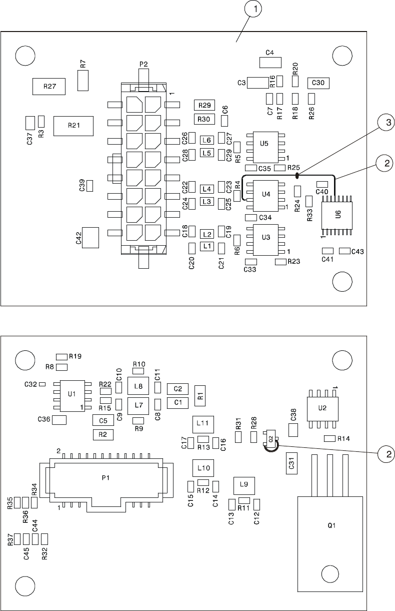
MM-E 2072-09333-00
B-118
COMPONENT SIDE
PRINT SIDE
Figure B-10. INTERCONNECTION Module, Identification of Components
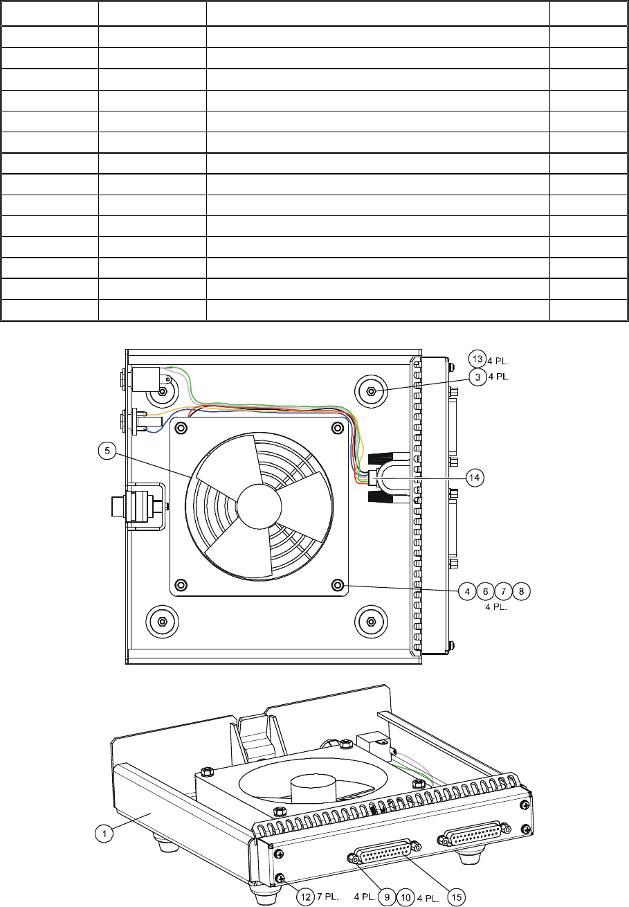
MM-E 2072-09333-00
B-119
Section III. COOLING TRAY
Table B-13. Cooling Tray Assembly, Parts List
Ref. Des. Mfg. Catalog No.
Description Qty.
BL1 2072-45037-00 COOLING TRAY Figure B-11
BL2 4056-90028-88 PROTECTIVE BUFFER 4.0
BL3 2072-52039-00 SCREW, M3×10, PHILIPS BLACK 4.0
BL4 4052-15008-00 CROSS COUNTERSUNK HEAD 4.0
BL5 2072-40970-00 GRILL FOR FAN, 1308116L0 1.0
BL6 2072-51002-00 NUT, M4X0.7 HEX SSTP 4.0
BL7 4053-15001-00 FLAT WASHER 8.0
BL8 4053-70002-16 WASHER, SPRING, M4 4.0
BL9 2072-41030-00 SPACER, 4-40 X 3116, 03MB 4.0
BL10 4053-16001-00 SPRING LOCKWASHERS, M3 4.0
BL12 4052-60246-88 SCREW, PH PHIL CRES, M 3X 7.0
BL13 2072-51004-00 NUT, M3 DIN 93,4 02MB0000 4.0
BL14 2072-93014-00 INTERNAL CABLE, 9 PIN TO FAN 1.0
BL15 2072-95235-00 FAN CONTROL MODULE 1.0
Figure B-11. Cooling Tray Assembly
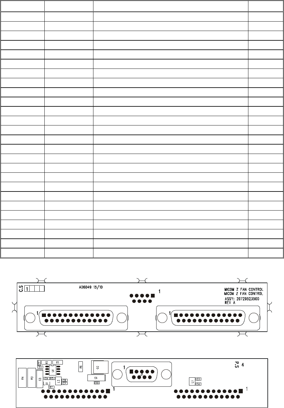
MM-E 2072-09333-00
B-120
Table B-14. FAN CONTROL Module, Parts List
Ref. Des. Mfg. Catalog No.
Description Qty.
2072-95235-00 FAN CONTROL MODULE Figure B-12
C1 4017-25282-00 CAPACITOR, 1NF, 06035A102JAT2A 1
C2 4017-25282-00 CAPACITOR, 1NF, 06035A102JAT2A 1
C3 4017-25282-00 CAPACITOR, 1NF, 06035A102JAT2A 1
C4 4017-25282-00 CAPACITOR, 1NF, 06035A102JAT2A 1
C5 4017-80112-02 CAPACITOR, 2.2UF, 293D225X0035C2T 1
C6 4017-80112-02 CAPACITOR, 2.2UF, 293D225X0035C2T 1
C7 4017-25279-00 CAPACITOR, 470PF, CM105CG471J50AT 1
C8 4017-25282-00 CAPACITOR, 1NF, 06035A102JAT2A 1
C9 4017-20271-00 CAPACITOR, 10NF, CM105X7R103K50AT 1
C10 4017-20271-00 CAPACITOR, 10NF, CM105X7R103K50AT 1
J1 4033-40091-02 CONNECTOR, 25 PIN, FEMALE, CD729S31D4 1
J2 4033-40093-02 CONNECTOR, CD7225S31D4 1
J3 4033-40093-02 CONNECTOR, CD7225S31D4 1
L1 4018-12206-00 INDUCTOR, 22 UH, NL252018T-220J 1
L2 4018-12206-00 INDUCTOR, 22 UH, NL252018T-220J 1
Q1 4021-00342-35 TRANSISTOR, PNP, MMBT3904LT1 1
Q2 4021-00179-35 TRANSISTOR, NPN, MJD2955T4 1
R1 4016-11100-10 RESISTOR, 1K, CRCW12061100FRT2 1
R2 4016-11001-10 RESISTOR, 1K, CRCW12061001FRT2 1
R3 4016-45110-10 RESISTOR, 511, CRCW25125110FR67 1
R4 4016-45110-10 RESISTOR, 511, CRCW25125110FR67 1
R5 4016-21002-10 RESISTOR, 10K, CRCW06031002FRT1 1
R6 4016-14750-10 RESISTOR, 475, CRCW12064750FRT2 1
R7 4016-25622-10 RESISTOR, 56.2K, CRCW06035622FRT1 1
U1 4021-20010-54 VOLTAGE REGULATOR, ADJUSTABLE, LP2951CMX 1
COMPONENT SIDE
PRINT SIDE
Figure B-12. FAN CONTROL Module, Identification of Components
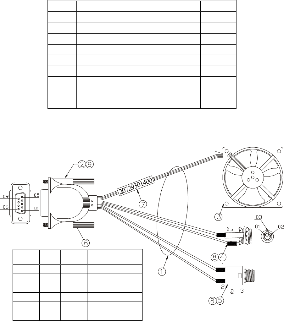
MM-E 2072-09333-00
B-121
Table B-15. Fan Harness Assembly, Parts List
Ref. Des.
Description Qty.
1 WIRE HARNESS Figure B-13
2 CONNECTOR, 9 PIN, D-TYPE, FEMALE 1
3 FAN, 298DHLP11000 1
4 5.3 mm DC PHONE JACK 1
5 1/4" PHONE JACK 1
6 SCREW, 4-40 UNC, 23.0 mm 2
7 LABEL 1
8 HEATSHRINK TUBING 4
9 OUTER MOLD, 45 PIN, PVC
Connector
P1
Connector
P2
Connector
P3
Connector
P4
Figure B-13. Fan Harness Assembly
Connector
P1 Color Connector
P2
Connector
P3
Connector
P4
1 Red 1
3 Black 2
4 Orange 1
5 Blue 2
7 Green 1
9 White 2
MM-E 2072-09333-00
B-122
Intentionally Left Blank