Electronic Systems Technology ESTEEM192CHP Data Packet Radio User Manual ESTeem Users Manual Model 192 Products
Electronic Systems Technology Data Packet Radio ESTeem Users Manual Model 192 Products
UserManual.wiki
>
Electronic Systems Technology
>
ESTEEM192CHP User Manual
Users Manual
Navigation menu
Upload a User Manual
Namespaces
Wiki Guide
HTML
PDF
Info
Views
User Manual
Discussion / Help
Navigation
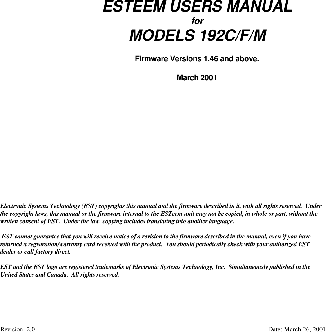

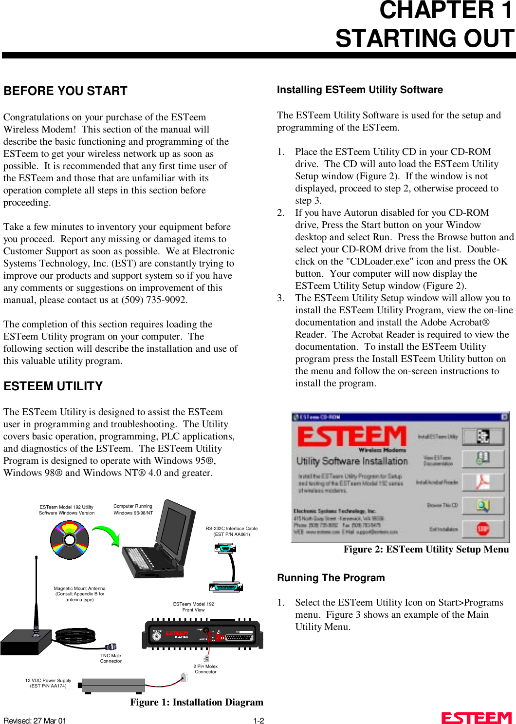
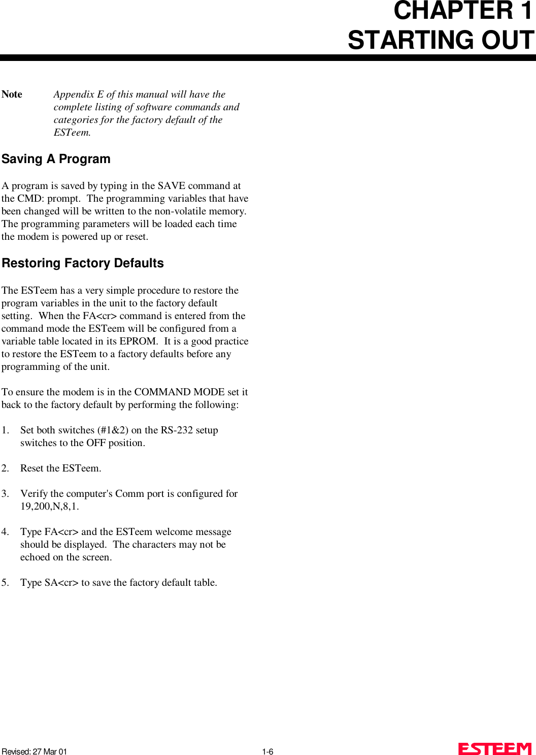
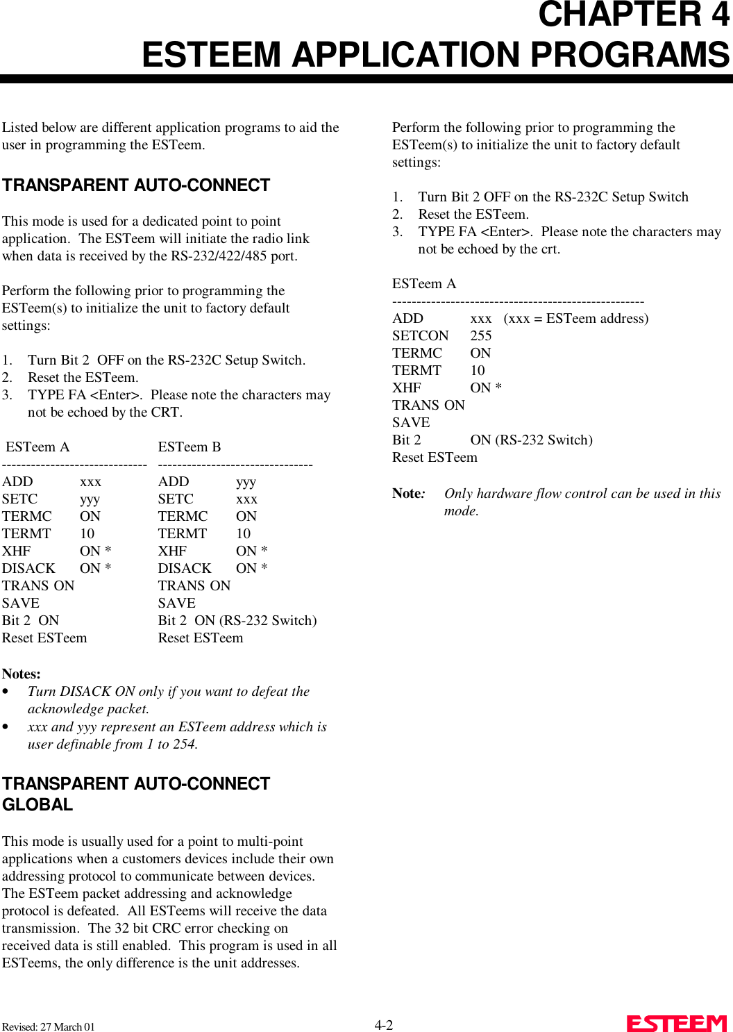
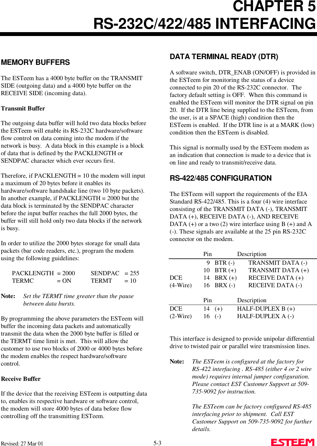
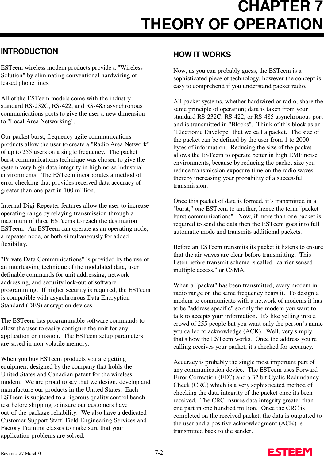
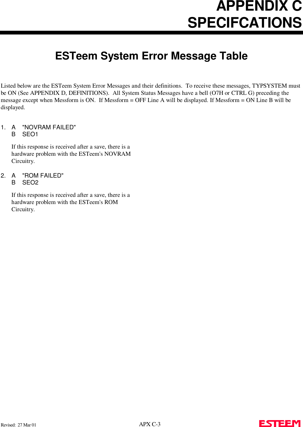
![CHAPTER 3PROGRAMMING ESTEEM FEATURESRevised: 27 March 01 3-4 Example Of Transmitted Data:[001]DATA Routes data to an ESTeem addressed 1.[100,200,250,1]DATA Routes data to an ESTeemaddressed 1 via ESTeemsaddressed 100, 200, and 250.The above example replaces the CONNECT commandfrom the COMMAND Mode. Received data packets will have the address of theESTeem that sent the data at the beginning of the datapacket.Example Of Received Data:[004]RECEIVED DATA Data received from anESTeem addressed 4.[030,100,244,004] Data received from an ESTeemaddressed 4 via ESTeemsaddressed 30, 100, and 244.MULTID (on/off) = On Enables this feature. Factorydefault = OFF.REMOTE PROGRAMMINGThe Remote Programming feature allows the user toremotely program ESTeems in his network. When aconnection has been made with the remote ESTeem theRPG: prompt will be displayed showing that you are nowin the COMMAND mode of that remote ESTeem.To enable this feature perform the following from theCOMMAND MODE:PROG (1-254) Address of destination ESTeem.Note: You can also use the Repeater routing(r1,r2,r3,da) to reach the destination ESTeem. (r1 = address of first repeater, r2 = address ofsecond repeater, etc. da = destination address).To end a remote programming session, hold Control andtype C (^C) and you will return to the COMMANDprompt of your ESTeem. There is a Watch Dog Timerthat will automatically disconnect you from remoteprogramming if there is no activity for thirty seconds.The REMPROG (on/off) feature is used to defeat theability of your ESTeem from being remotelyprogrammed. If REMPROG = OFF another ESTeemcannot remotely program your unit. Factory default =ON.SECURITYThe Security feature allows the user to lock outprogramming of the ESTeem. REMEMBER TO STOREYOUR CODE NUMBER IN A SAFE PLACE.To enable this feature perform the following from theCOMMAND MODE:SECURITY (1 to 100,000) Entering a securitynumber enables thesecurity feature. SAVE To enter the security code permanently into theESTeem memory.Note: When enabled, the ESTeem will output a“Security On” message.To disable the security feature perform the followingfrom the COMMAND mode.SECURITY (1 to 100,000) Entering your securitynumber disables thesecurity feature. SAVE To remove the security code permanently fromthe ESTeem memory.Note: When disabled, the ESTeem will output a“Security Off” message.](https://usermanual.wiki/Electronic-Systems-Technology/ESTEEM192CHP/User-Guide-356175-Page-17.png)
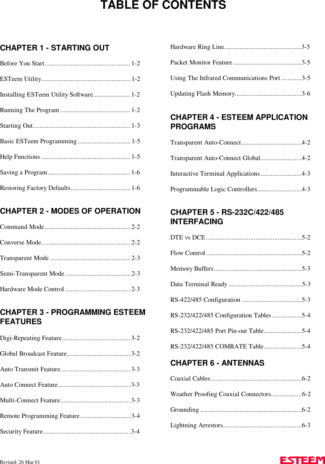
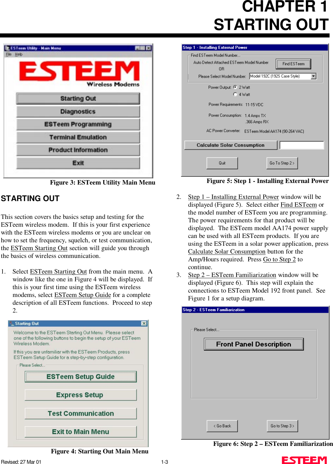
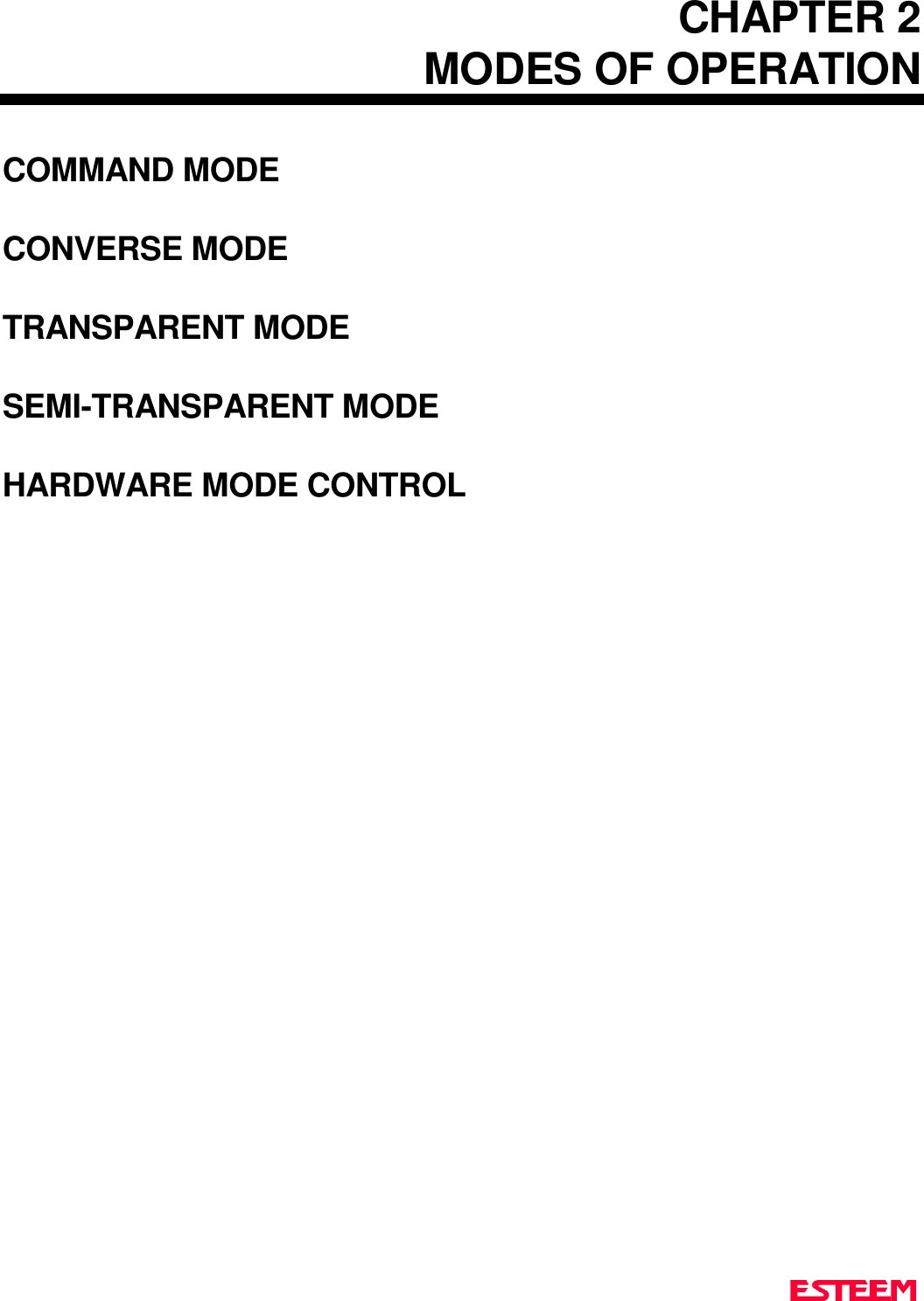
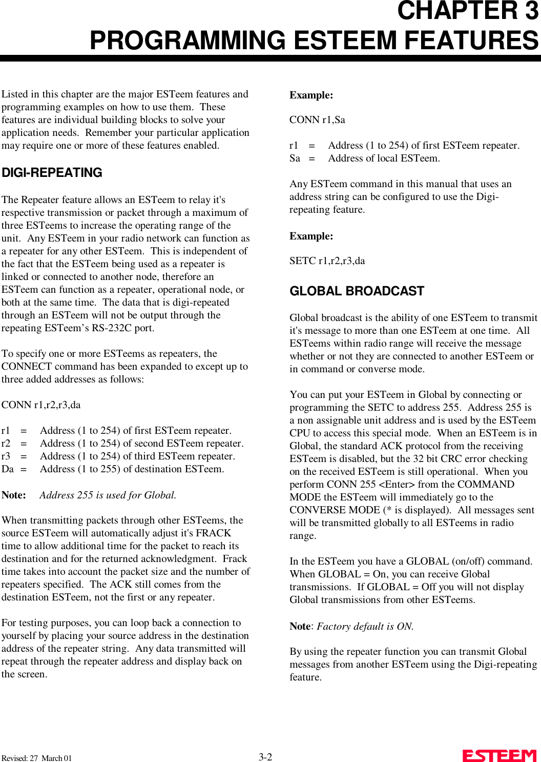
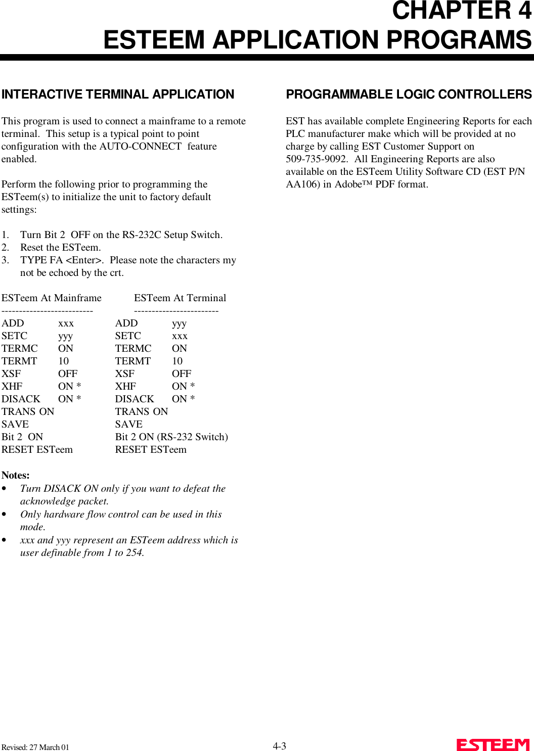
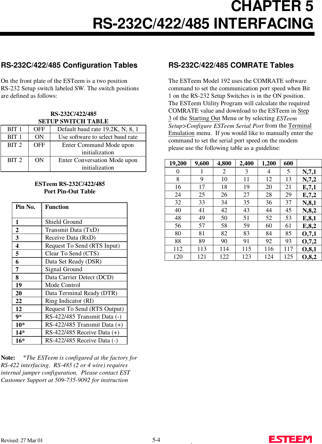
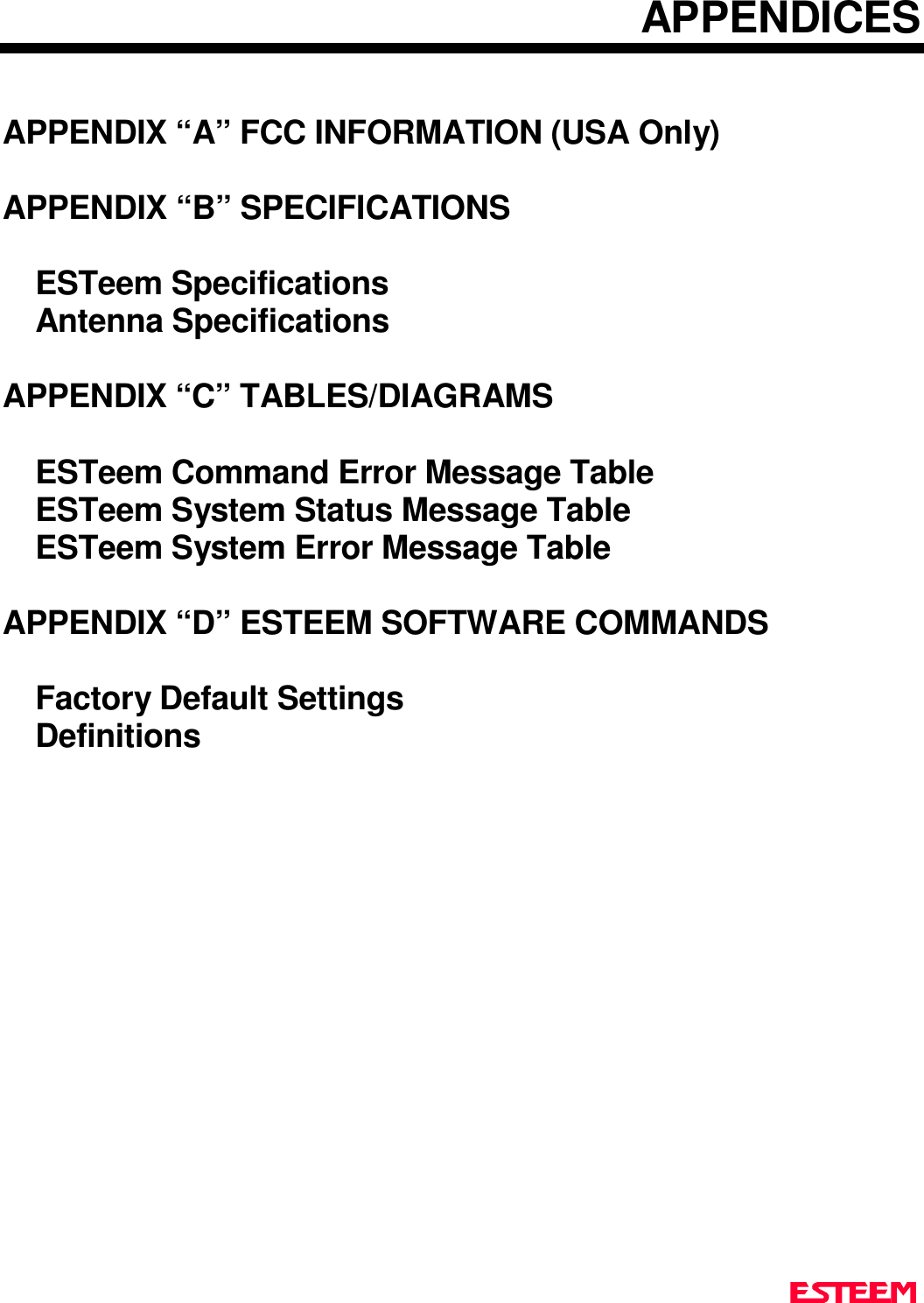
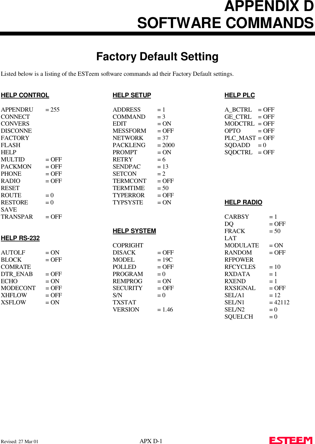
![CHAPTER 3PROGRAMMING ESTEEM FEATURESRevised: 27 March 01 3-5 HARDWARE RING LINE (Factory Option)When the ESTeem establishes a CONNECT or link withanother ESTeem (T/E Light on solid), pin 22 at theESTeem RS-232C will change from a -15 vdc voltagestate to a +15 vdc voltage state. The RING softwarecommand allows the user to change the output from alatched state to a pulsed state. To change the state of thisline program the following from the COMMAND mode. Factory default = LATCH.RING =Latch. Pin 22 is high when the ESTeem T/Elight is on solid.RING =Pulse. Pin 22 is pulsed (positive 250 ms.) whenthe ESTeem T/E light is on solid.PACKET MONITORThe PACKM [ON/OFF] command places the ESTeem ina special packet monitor mode. When this feature isenabled the ESTeem is placed in a receive only mode andwill not function as a normal ESTeem. The ESTeem willmonitor and report the status of all message traffic withinthe network in the following format, the actual packetmessage will not be outputted.SA-xxx, DA-xxx, Type Code, R1-Repeater Status, R2-Repeater Status, R3-Repeater Status, Data Bytes Sentxxx = ESTeem AddressDA = Destination ESTeemSA = Source ESTeemR1 = Address of first ESTeem repeater.R2 = Address of second ESTeem repeater.R3 = Address of third ESTeem repeater.Type CodesI = InformationDISC = DisconnectedRR = Receive ReadyUA = Unnumbered AcknowledgeRNR = Receive Not ReadyFRMR = Frame RejectREJ = RejectDM = Disconnected ModeUI = Unnumbered InformationSABM = Set Async. Balance ModeRepeater StatusP=PendingD= DoneUSING THE INFRAREDCOMMUNICATIONS PORTThe infrared (IR) communications port will allow you toprogram and interrogate the ESTeem withoutdisconnecting the serial cable from the back of themodem. The IR port is located on the front panel of theESTeem, above the T/E light.To communicate from a computer to the ESTeemthrough the IR port you will need a copy of the ESTeemUtilities (Version 4.0 or higher) and an ESTeem IRCommunication Dongle (ESTeem P/N AA300).Connect the dongle directly to the serial port of thecomputer. The dongle requires initialization from theESTeem Utilities. From the Terminal Emulation screenpress the F3 function key to initialize the dongle. If themodem is not in the COMMAND mode, press CTRL-Cto display the CMD: prompt.Note:With Switch 2 (RS-232 Setup) in the On positionthe ESTeem defaults the IR port to the commandmode.ANTENNAS/N:T/ETXRXPWRIRPortPhoneModel 192SAntenna 12 VDCRESETInfrared Communications Port forRemote Programming and DiagnosticsWithout Interruption Of The WirelessRadio Area NetworkIR Communications Dongal(EST p/n AA300)3 ft. RangeRESETFigure 1: Using The IR Port](https://usermanual.wiki/Electronic-Systems-Technology/ESTEEM192CHP/User-Guide-356175-Page-18.png)

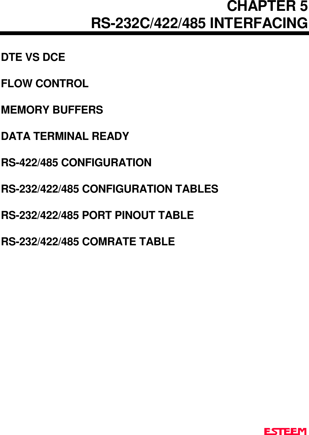
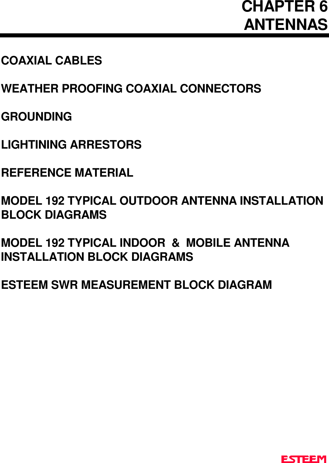


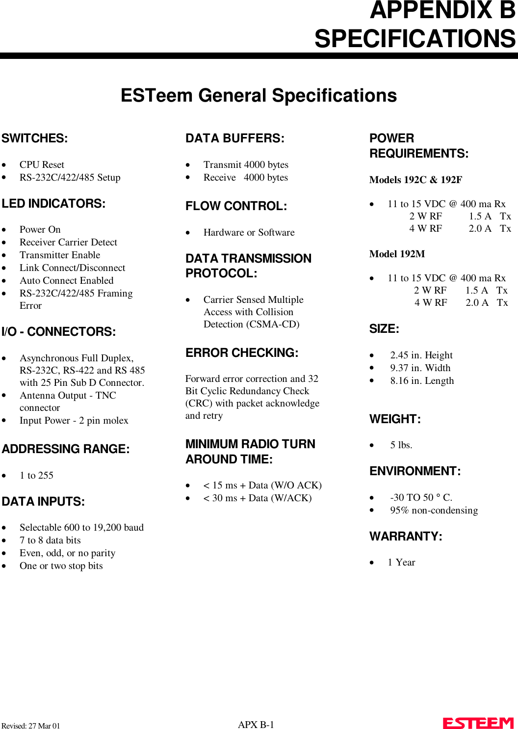


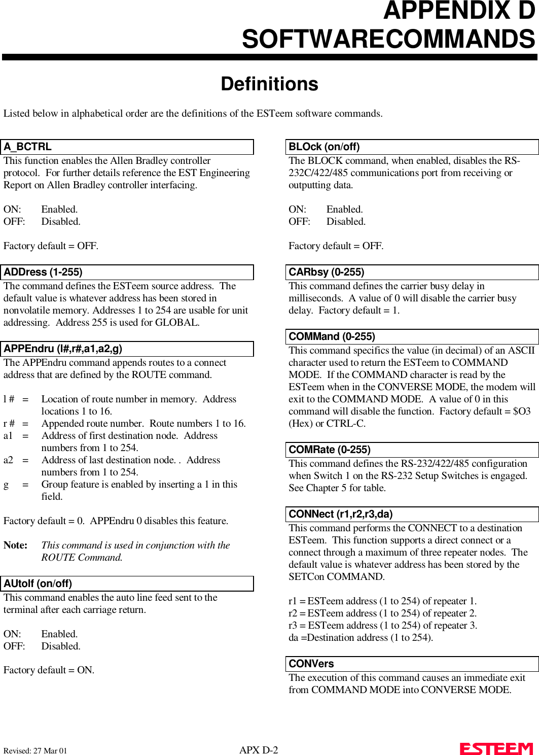
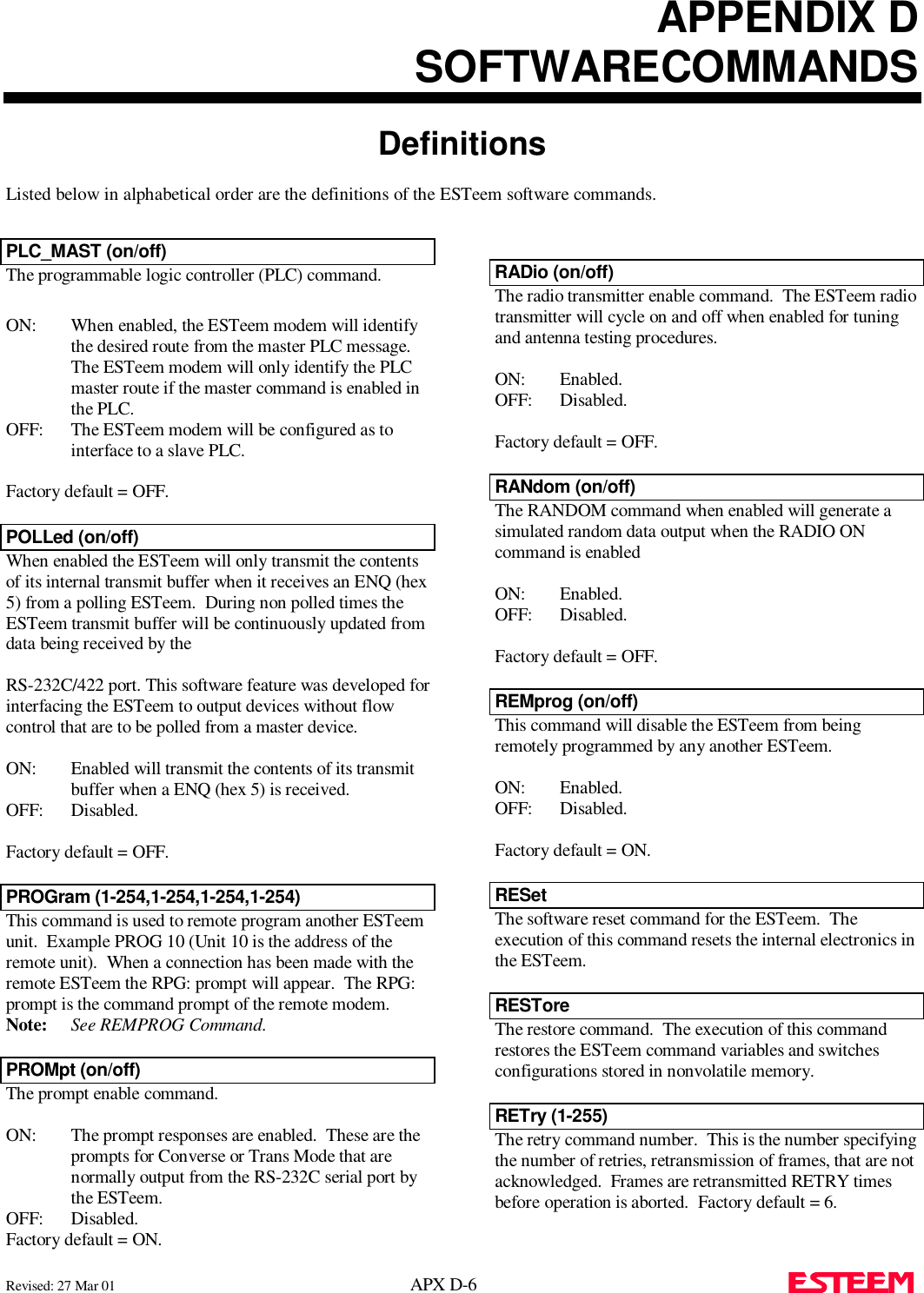
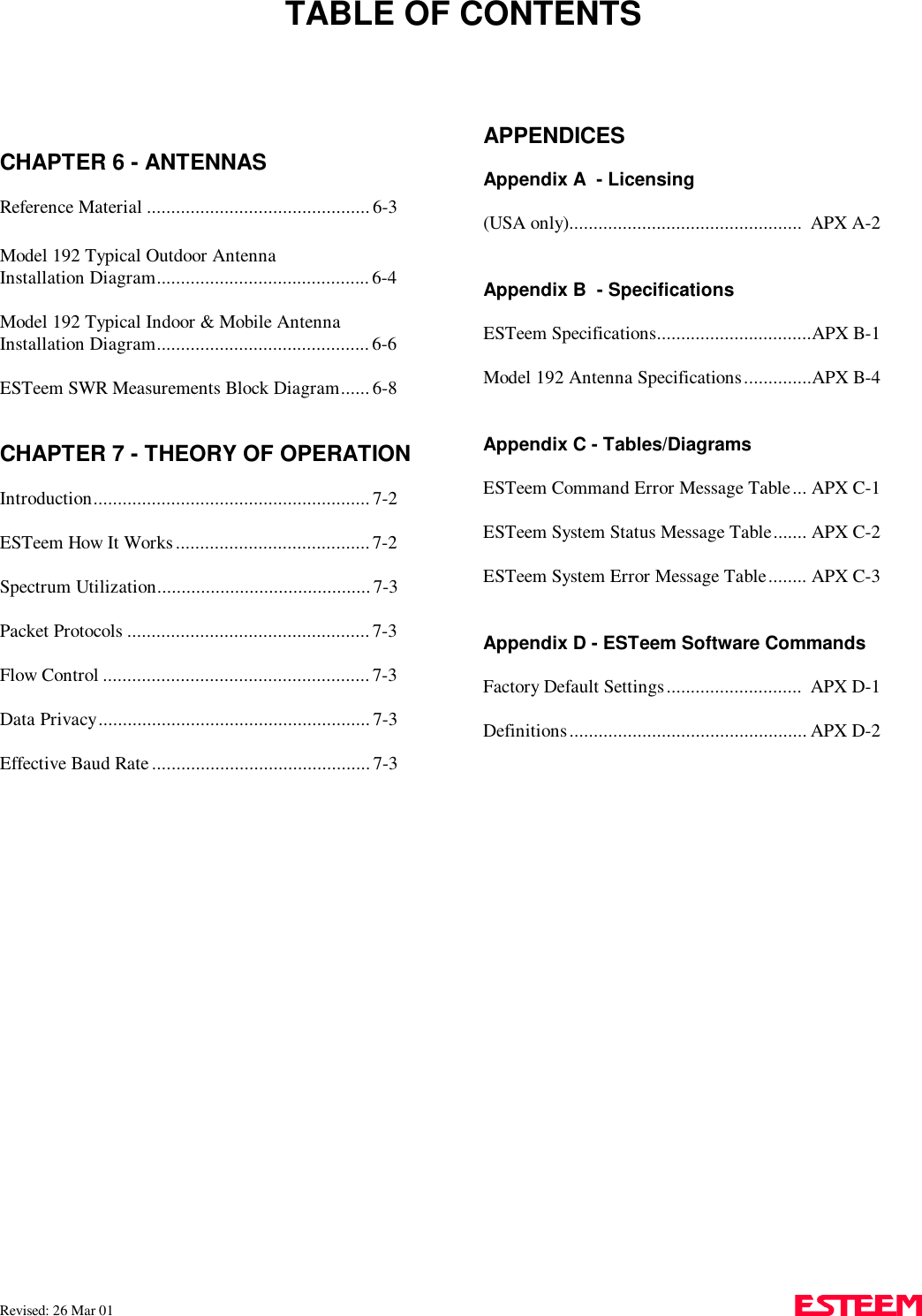
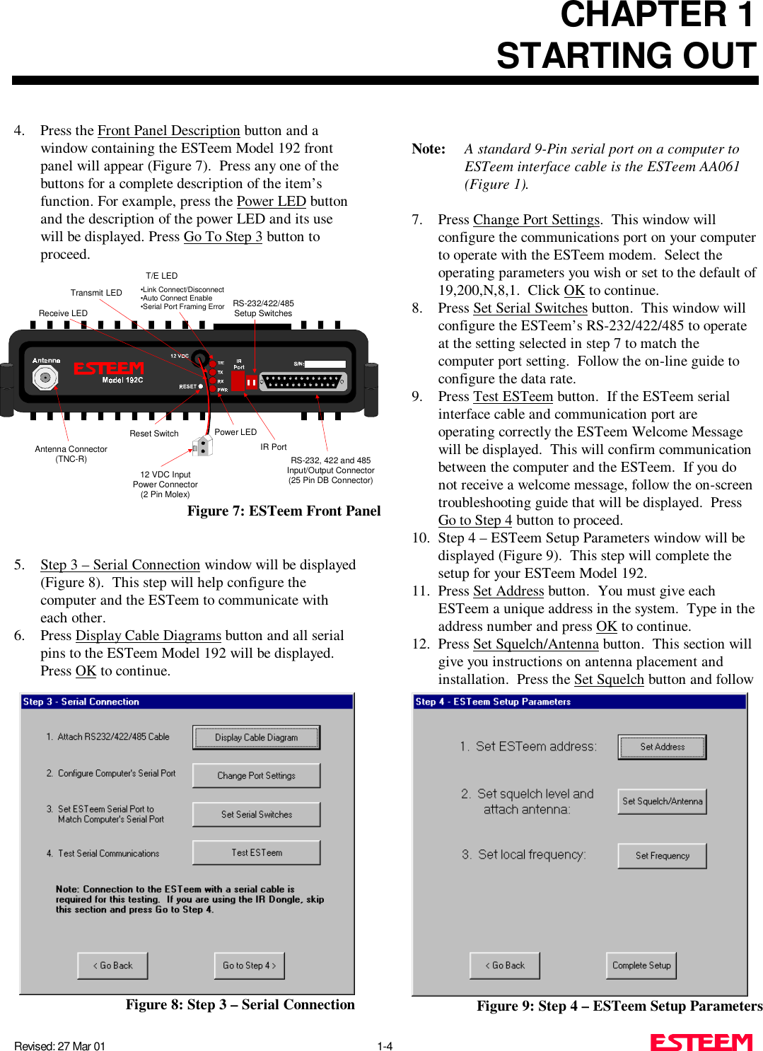
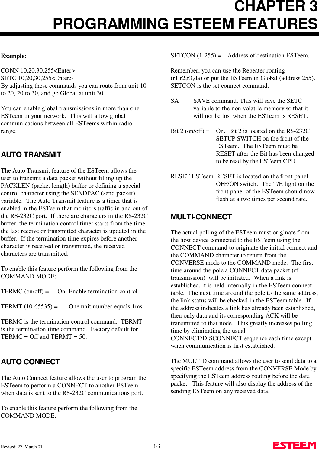
![APPENDIX DSOFTWARECOMMANDSDefinitionsListed below in alphabetical order are the definitions of the ESTeem software commands.Revised: 27 Mar 01 APX D-4 HElpHELP switches are:HELP Displays this Help menu.HELP ALL Displays All commands switchesand arguments.HELP CHANGE Displays only the commands thatare changed from factory default.HELP CONTROL Displays Control commandsswitches and arguments.HELP PLC Displays PLC commands switchesand arguments.HELP RADIO Displays Radio commands switchesand arguments.HELP RS-232 Displays RS232 commandsswitches and arguments.HELP SETUP Displays Setup commands switchesand arguments.HELP SYSTEM Displays System commandsswitches and arguments.JOHNctrl (on/off)This function enables the Johnson controller protocol. Forfurther detail Reference the EST Engineering Report onJohnson controller interfacing. ON: Enabled.OFF: Disabled.Factory default = OFF.LATLatches the selection of the desired serial frequencysynthesizer on the Tx/Rx cardMESSform (on/off)When enabled all of the system status and error messageswill be in a formatted form."xx" indicates what error or message (See ErrorMessages and System Status Messages).EMxx <CR> [ESTeem Error Messages]SExx <CR> [System Error Messages]SSxx <CR> [System Status Messages]SSxx-xxxx <CR> [System Status MessageW/Returned Value]ON: Enabled.OFF: Disabled.Factory default = OFF.MOdecontr (on/off)ON: The mode of the ESTeem modem is controlled bypin 19 of the RS-232C connector. A low (0)directs the ESTeem into the COMMAND mode. A high (1) directs the ESTeem intoCONVERSE/TRANSPARENT mode.OFF: The mode of the ESTeem modem is controlled byASCII character.Factory default = OFFMODEL (xx)Displays the product model of default firmware that isinstalled. Model should be the same as product being used.Listed below are the model codes19C = ESTeem Model 192C19F = ESTeem Model 192F19V = ESTeem Model 192VMODCTRLThis command enables the Modicon controller protocol. For further detail Reference the EST Engineering Reporton Modicon controller interfacing. OFF: Disabled.Factory default = OFF.](https://usermanual.wiki/Electronic-Systems-Technology/ESTEEM192CHP/User-Guide-356175-Page-55.png)
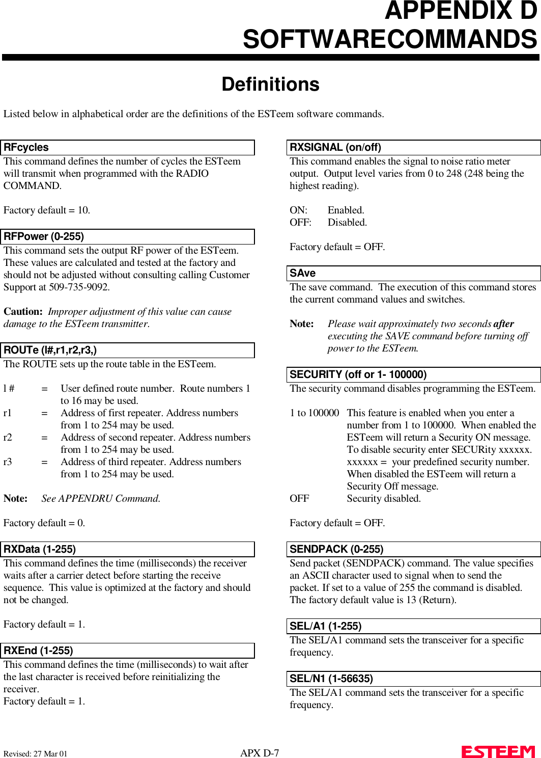
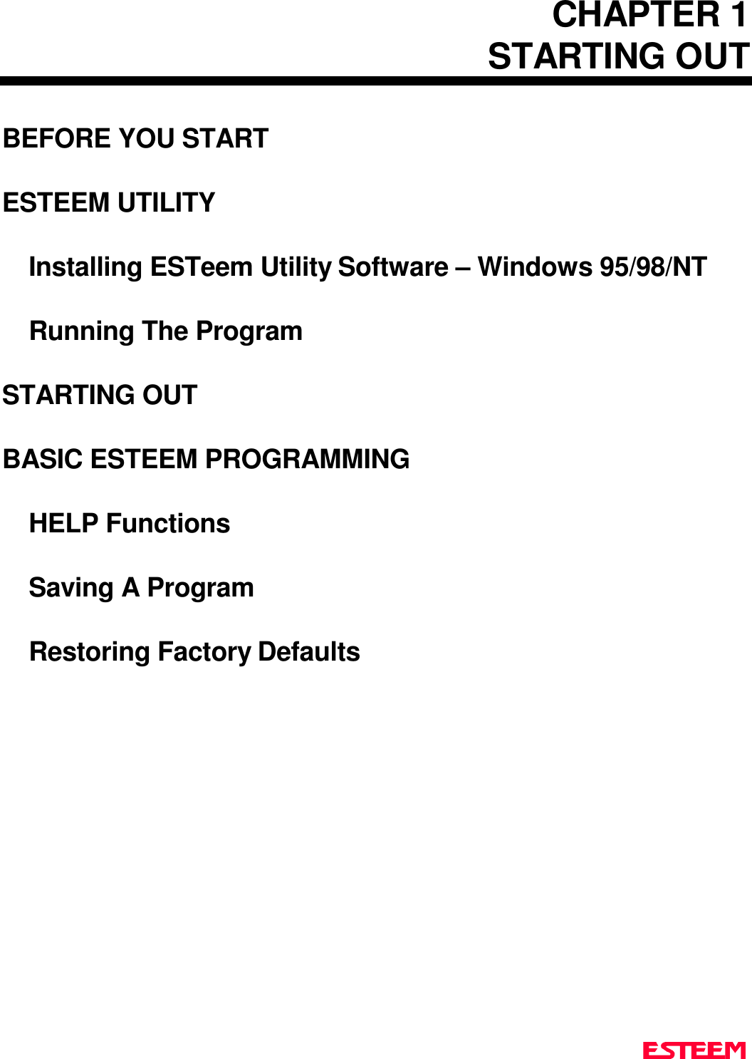
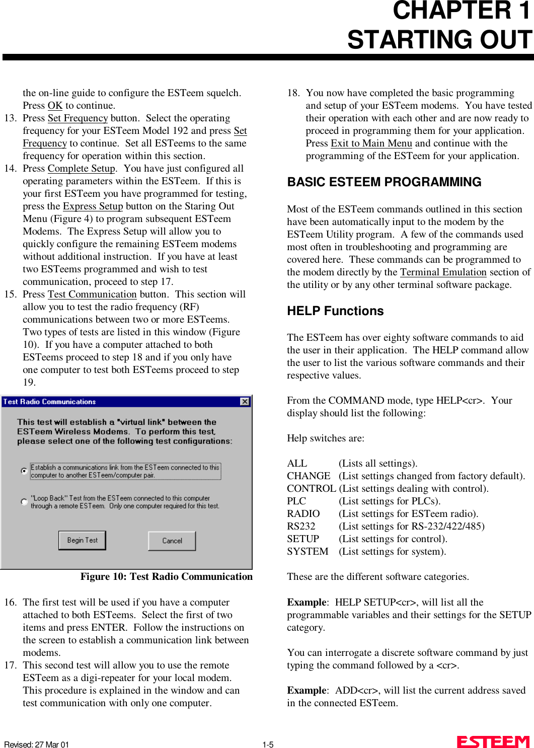
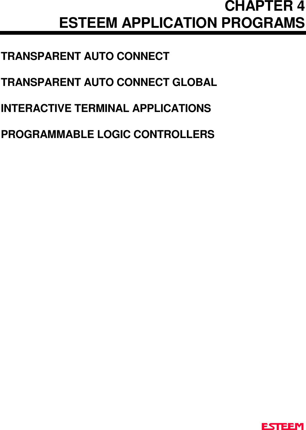
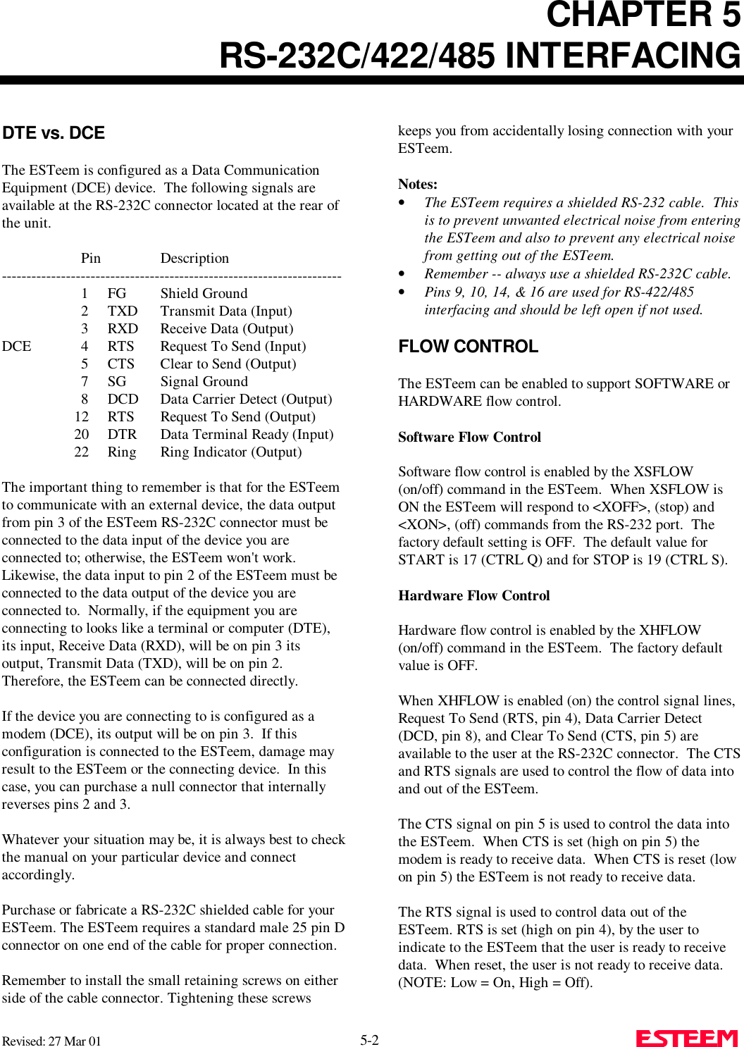
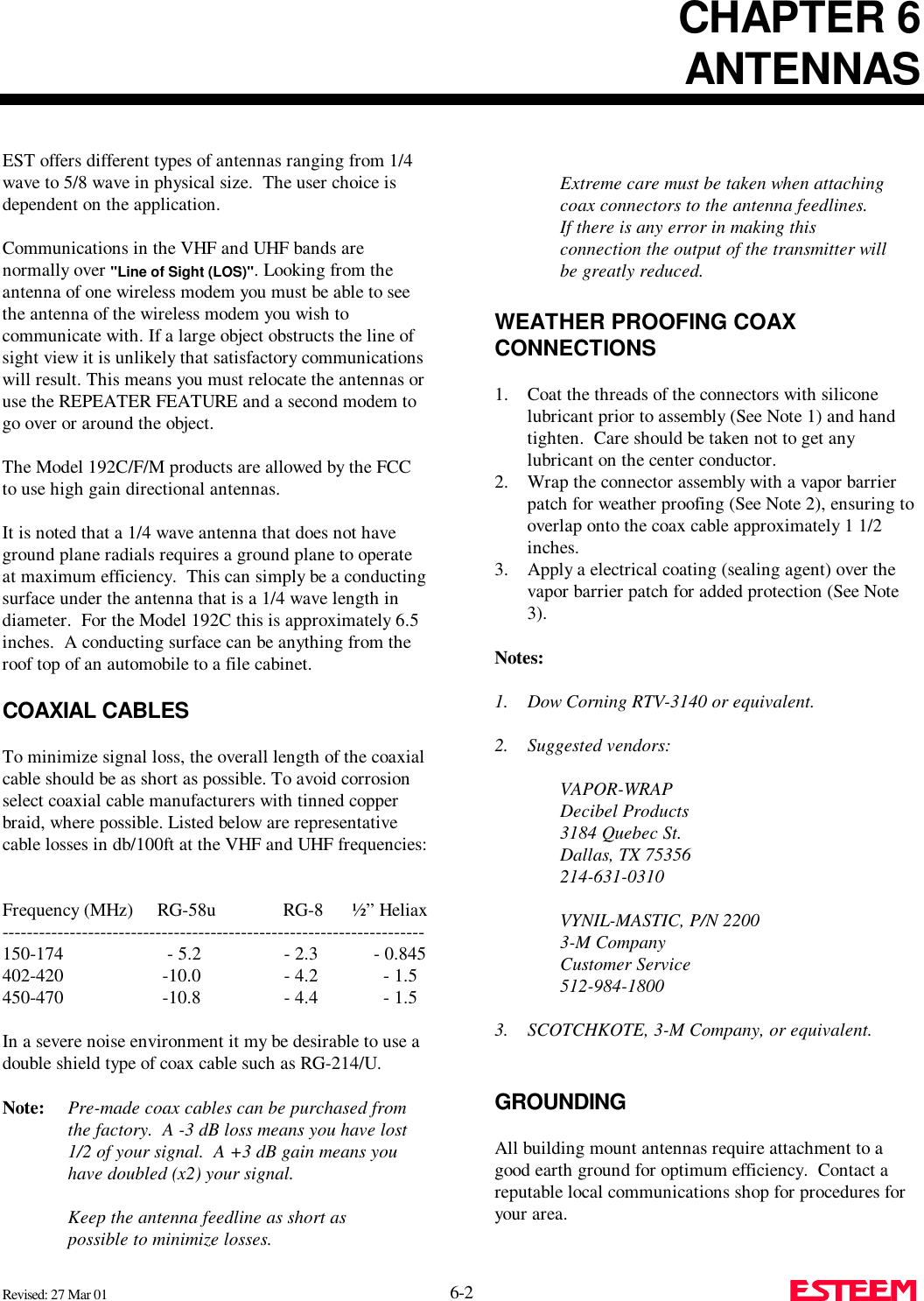
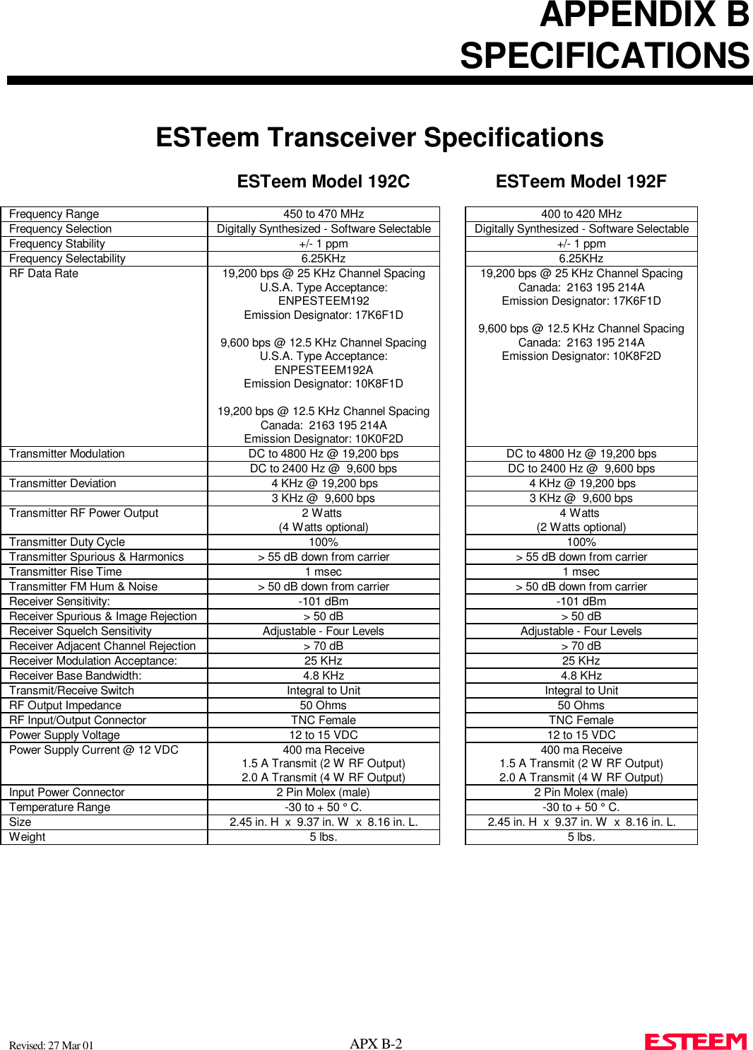
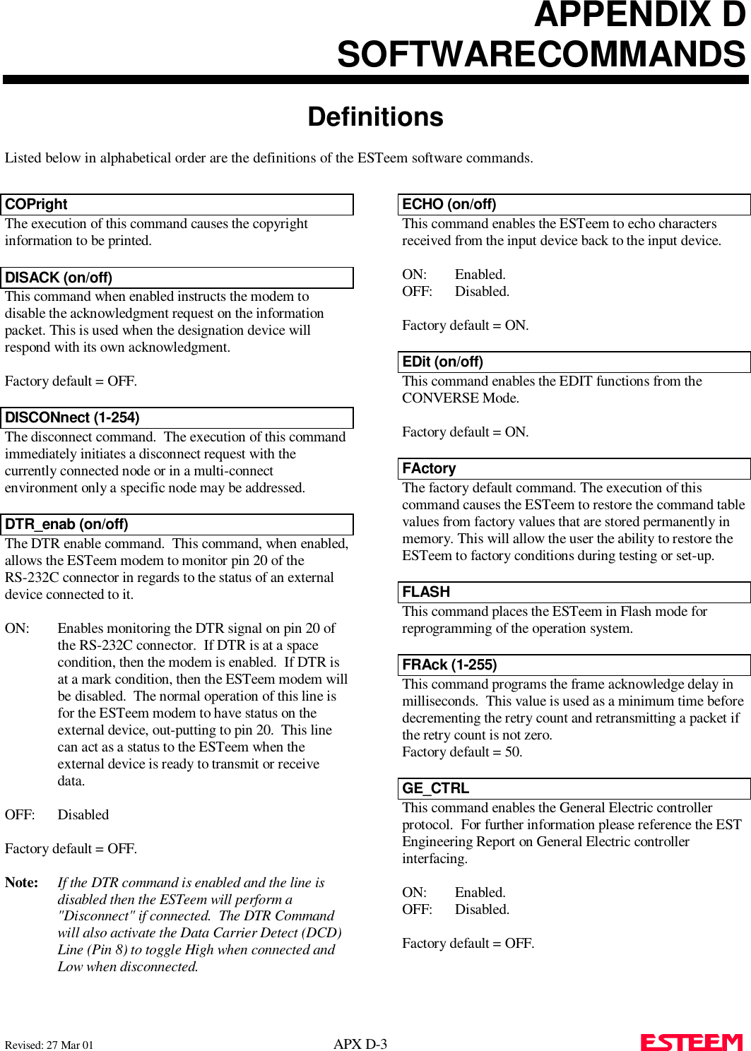
![APPENDIX DSOFTWARECOMMANDSDefinitionsListed below in alphabetical order are the definitions of the ESTeem software commands.Revised: 27 Mar 01 APX D-5 MODUlate (on/off)The radio modulate command. When enabled will transmita modulated test signal when the RADIO ON command isenabled.ON: Enabled.OFF: Disabled.Factory default = OFF.MOORE (on/off)This function enables the Moore products using Hartprotocol. For further details reference the EST EngineeringReport on Moore Products interfacing. ON: Enabled.OFF: Disabled.Factory default = OFF.MULTID (on/off)This command when enabled allows the ESTeem User tosend data to another ESTeem from the CONVERSEMODE by specifying the routing address before the data.ON: Enabled.OFF: Disabled.Factory default = OFF.Example Of Transmitted Data:[001]DATA Routes data to an ESTeem addressed 1.[100,200,250,1]DATA Routes data to an ESTeemaddressed 1 via ESTeemsaddressed 100, 200, and 250.This replaces using the CONNECT command from theCOMMAND Mode. Received data packets will have theaddress of the ESTeem that sent the data at the beginningof the data packet.Example Of Received Data:[004]RECEIVED DATA Data received from an ESTeemaddressed 4.[030,100,244,004] Data received from an ESTeemaddressed 4 via ESTeemsaddressed 30, 100, and 244.NETwork (0-255)Network identification code. This is used to program acommon code for all modems in the customers network sothat another facility on your frequency using the sameaddresses will not interfere with your equipment. Factorydefault = 37.OPTO (on/off)This function enables the Opto 22 protocol. For furtherdetails reference the EST Engineering Report on Opto 22interfacing. ON: Enabled.OFF: Disabled.Factory default = OFF.PACKleng (1-2000)This command defines the length of the data packet inbytes. Factory default = 2000.PACKMon (on/off)Places the ESTeem in the packet monitor mode. Factorydefault = OFF.PHone (on/off)Phone port enable command. The ESTeem will answer anincoming call when enabled.ON: Enabled.OFF: Disabled.Factory default = OFF.](https://usermanual.wiki/Electronic-Systems-Technology/ESTEEM192CHP/User-Guide-356175-Page-56.png)