Electronic Systems Technology ESTEEM192CHP Data Packet Radio User Manual ESTeem Users Manual Model 192 Products
Electronic Systems Technology Data Packet Radio ESTeem Users Manual Model 192 Products
Users Manual

Revision: 2.0 Date: March 26, 2001
Electronic Systems Technology (EST) copyrights this manual and the firmware described in it, with all rights reserved. Under
the copyright laws, this manual or the firmware internal to the ESTeem unit may not be copied, in whole or part, without the
written consent of EST. Under the law, copying includes translating into another language.
EST cannot guarantee that you will receive notice of a revision to the firmware described in the manual, even if you have
returned a registration/warranty card received with the product. You should periodically check with your authorized EST
dealer or call factory direct.
EST and the EST logo are registered trademarks of Electronic Systems Technology, Inc. Simultaneously published in the
United States and Canada. All rights reserved.
ESTEEM USERS MANUAL
for
MODELS 192C/F/M
Firmware Versions 1.46 and above.
March 2001

Revised: 26 Mar 01
PRODUCT WARRANTY
Electronic Systems Technology, Inc., (hereinafter EST)
expressly warrants its products as free of manufacturing
defects for a period of one year from the date of sale to
first user/customer.
THERE ARE NO OTHER WARRANTIES, EXPRESS
OR IMPLIED AND THERE IS EXPRESSLY
EXCLUDED ALL WARRANTIES OF
MERCHANTABILITY OR FITNESS FOR A
PARTICULAR PURPOSE. NO OTHER WARRANTY
GIVEN BY ANY EMPLOYEE, AGENT,
DISTRIBUTOR OR OTHER PERSON WITH
RESPECT TO THE PRODUCT SHALL BE BINDING
ON EST.
LIMITATION OF LIABILITY:
EST's liability shall be limited to refunding of purchase
price, repair or replacement of product.
IN NO EVENT SHALL EST HAVE LIABILITY FOR
CONSEQUENTIAL, INCIDENTAL, SPECIAL OR
EXEMPLARY DAMAGES CAUSED DIRECTLY OR
INDIRECTLY BY THE PRODUCT, INCLUDING
BUT NOT LIMITED TO ANY INTERRUPTION OF
SERVICES, LOSS OF BUSINESS OR
ANTICIPATORY PROFITS. IN NO EVENT SHALL
EST BE LIABLE FOR ANY DAMAGES
WHATSOEVER IN EXCESS OF THE PURCHASE
PRICE OF THE PRODUCT.
In the event that a unit or part requires replacement or
factory servicing, the following conditions apply:
a) Customer must obtain from EST an authorized
RMA (Return Materials Authorization) number
(call 509-735-9092 Customer Support) before
shipment of product or parts to EST for any
reason;
b) If the whole unit is shipped, it must be in its
original carton and shipping components, or a
carton and shipping components supplied by
EST, or if parts only are shipped, they must be
packaged and cushioned so as to prevent
damage in transit and shipped freight prepaid;
PRODUCT WILL BE CONSIDERED OUT OF
WARRANTY IF:
a) If the product is damaged due to improper or
abnormal use, abuse, mishandling, accident or
improper maintenance or failure to follow
operating instruction;
b) If the product is defective as a result of sand,
dirt, or water damage;
c) If any factory-sealed enclosure has been opened
or shows evidence of an attempt to be opened;
d) If defects or damage are caused by the use of
unauthorized parts or unauthorized service;
e) If the product has had its serial numbers altered
or removed.
Warranty repair form must be accompanied by proof of
user's purchase of unit. Product must be shipped to the
manufacturer at the following address:
Electronic Systems Technology
415 North Quay Street
Kennewick, Washington USA 99336
ADDITIONAL SERVICE:
If EST releases an improvement update to firmware
internal to the ESTeem unit during the 90 day period
after the unit was purchased by the first user/customer,
EST will update the applicable unit with the revised
version at no charge other than for UPS handling and
shipping to and from your location to the EST factory.
Return of any such item must be accompanied with proof
of purchase.

TABLE OF CONTENTS
Revised: 26 Mar 01
CHAPTER 1 - STARTING OUT
Before You Start.................................................. 1-2
ESTeem Utility....................................................1-2
Installing ESTeem Utility Software......................1-2
Running The Program......................................... 1-2
Starting Out......................................................... 1-3
Basic ESTeem Programming...............................1-5
Help Functions ....................................................1-5
Saving a Program................................................1-6
Restoring Factory Defaults................................... 1-6
CHAPTER 2 - MODES OF OPERATION
Command Mode..................................................2-2
Converse Mode....................................................2-2
Transparent Mode ............................................... 2-3
Semi-Transparent Mode ......................................2-3
Hardware Mode Control ...................................... 2-3
CHAPTER 3 - PROGRAMMING ESTEEM
FEATURES
Digi-Repeating Feature........................................3-2
Global Broadcast Feature.....................................3-2
Auto Transmit Feature.........................................3-3
Auto Connect Feature..........................................3-3
Multi-Connect Feature......................................... 3-3
Remote Programming Feature .............................3-4
Security Feature...................................................3-4
Hardware Ring Line.............................................3-5
Packet Monitor Feature........................................3-5
Using The Infrared Communications Port ............3-5
Updating Flash Memory.......................................3-6
CHAPTER 4 - ESTEEM APPLICATION
PROGRAMS
Transparent Auto-Connect...................................4-2
Transparent Auto-Connect Global........................4-2
Interactive Terminal Applications........................4-3
Programmable Logic Controllers..........................4-3
CHAPTER 5 - RS-232C/422/485
INTERFACING
DTE vs DCE........................................................5-2
Flow Control........................................................5-2
Memory Buffers...................................................5-3
Data Terminal Ready...........................................5-3
RS-422/485 Configuration ...................................5-3
RS-232/422/485 Configuration Tables .................5-4
RS-232/422/485 Port Pin-out Table......................5-4
RS-232/422/485 COMRATE Table......................5-4
CHAPTER 6 - ANTENNAS
Coaxial Cables.....................................................6-2
Weather Proofing Coaxial Connectors..................6-2
Grounding ...........................................................6-2
Lightning Arrestors..............................................6-3

TABLE OF CONTENTS
Revised: 26 Mar 01
CHAPTER 6 - ANTENNAS
Reference Material ..............................................6-3
Model 192 Typical Outdoor Antenna
Installation Diagram............................................6-4
Model 192 Typical Indoor & Mobile Antenna
Installation Diagram............................................6-6
ESTeem SWR Measurements Block Diagram...... 6-8
CHAPTER 7 - THEORY OF OPERATION
Introduction......................................................... 7-2
ESTeem How It Works........................................7-2
Spectrum Utilization............................................ 7-3
Packet Protocols .................................................. 7-3
Flow Control .......................................................7-3
Data Privacy........................................................7-3
Effective Baud Rate............................................. 7-3
APPENDICES
Appendix A - Licensing
(USA only)................................................ APX A-2
Appendix B - Specifications
ESTeem Specifications................................APX B-1
Model 192 Antenna Specifications..............APX B-4
Appendix C - Tables/Diagrams
ESTeem Command Error Message Table... APX C-1
ESTeem System Status Message Table....... APX C-2
ESTeem System Error Message Table........ APX C-3
Appendix D - ESTeem Software Commands
Factory Default Settings............................ APX D-1
Definitions................................................. APX D-2

CHAPTER 1
STARTING OUT
Revised: 27 Mar 01 1-2
BEFORE YOU START
Congratulations on your purchase of the ESTeem
Wireless Modem! This section of the manual will
describe the basic functioning and programming of the
ESTeem to get your wireless network up as soon as
possible. It is recommended that any first time user of
the ESTeem and those that are unfamiliar with its
operation complete all steps in this section before
proceeding.
Take a few minutes to inventory your equipment before
you proceed. Report any missing or damaged items to
Customer Support as soon as possible. We at Electronic
Systems Technology, Inc. (EST) are constantly trying to
improve our products and support system so if you have
any comments or suggestions on improvement of this
manual, please contact us at (509) 735-9092.
The completion of this section requires loading the
ESTeem Utility program on your computer. The
following section will describe the installation and use of
this valuable utility program.
ESTEEM UTILITY
The ESTeem Utility is designed to assist the ESTeem
user in programming and troubleshooting. The Utility
covers basic operation, programming, PLC applications,
and diagnostics of the ESTeem. The ESTeem Utility
Program is designed to operate with Windows 95®,
Windows 98® and Windows NT® 4.0 and greater.
Installing ESTeem Utility Software
The ESTeem Utility Software is used for the setup and
programming of the ESTeem.
1. Place the ESTeem Utility CD in your CD-ROM
drive. The CD will auto load the ESTeem Utility
Setup window (Figure 2). If the window is not
displayed, proceed to step 2, otherwise proceed to
step 3.
2. If you have Autorun disabled for you CD-ROM
drive, Press the Start button on your Window
desktop and select Run. Press the Browse button and
select your CD-ROM drive from the list. Double-
click on the "CDLoader.exe" icon and press the OK
button. Your computer will now display the
ESTeem Utility Setup window (Figure 2).
3. The ESTeem Utility Setup window will allow you to
install the ESTeem Utility Program, view the on-line
documentation and install the Adobe Acrobat®
Reader. The Acrobat Reader is required to view the
documentation. To install the ESTeem Utility
program press the Install ESTeem Utility button on
the menu and follow the on-screen instructions to
install the program.
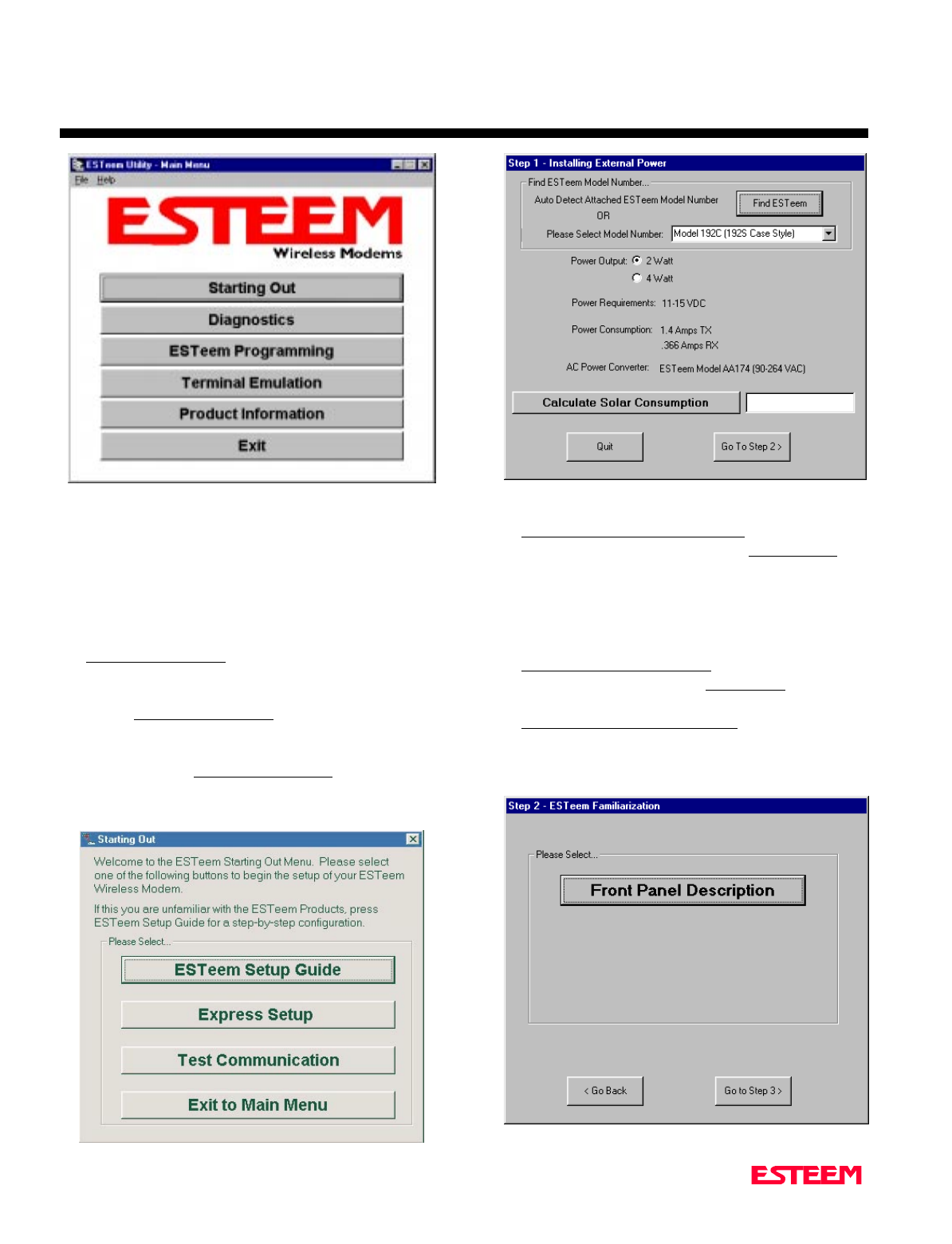
Running The Program
1. Select the ESTeem Utility Icon on Start>Programs
menu. Figure 3 shows an example of the Main
Utility Menu.
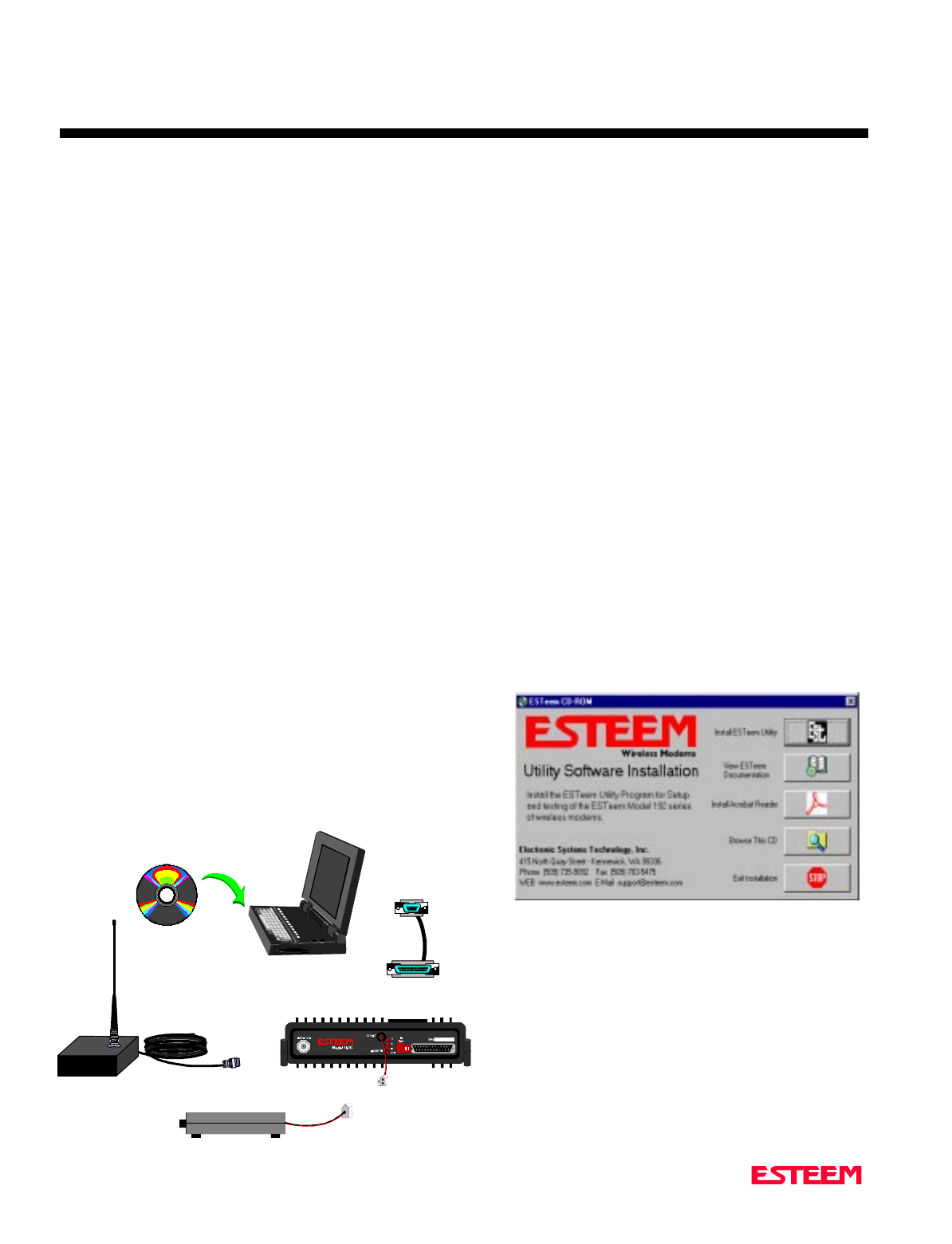
Figure 2: ESTeem Utility Setup Menu
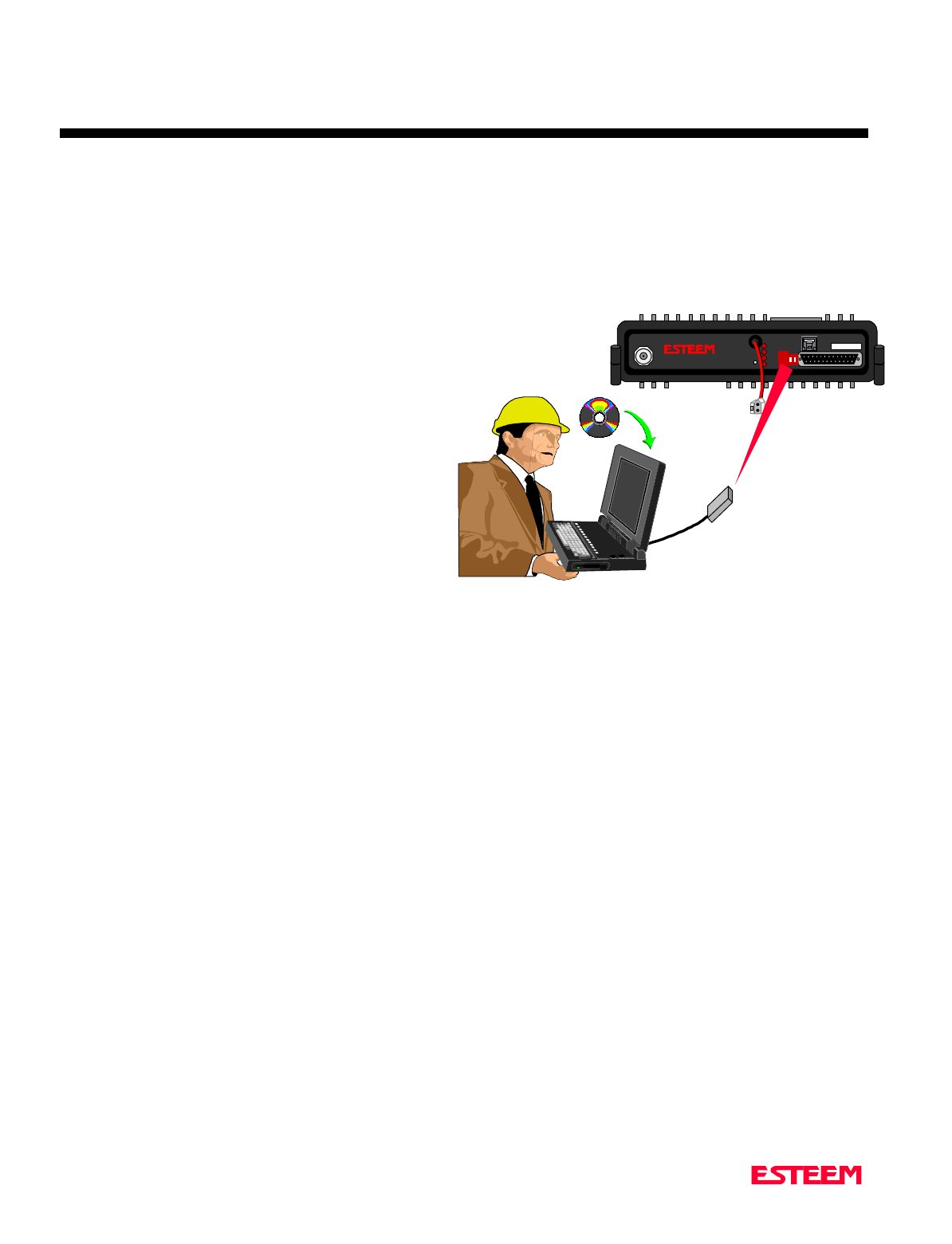
RS-232C Interface Cable
(EST P/N AA061)
12 VDC Power Supply
(EST P/N AA174)
2 Pin Molex
Connector
ESTeem Model 192
Front View
ESTeem Model 192 Utility
Software Windows Version
Computer Running
Windows 95/98/NT
TNC Male
Connector
Magnetic Mount Antenna
(Consult Appendix B for
antenna type)
Figure 1: Installation Diagram
CHAPTER 1
STARTING OUT
Revised: 27 Mar 01 1-3
STARTING OUT
This section covers the basics setup and testing for the
ESTeem wireless modem. If this is your first experience
with the ESTeem wireless modems or you are unclear on
how to set the frequency, squelch, or test communication,
the ESTeem Starting Out section will guide you through
the basics of wireless communication.
1. Select ESTeem Starting Out from the main menu. A
window like the one in Figure 4 will be displayed. If
this is your first time using the ESTeem wireless
modems, select ESTeem Setup Guide for a complete
description of all ESTeem functions. Proceed to step
2.
2. Step 1 – Installing External Power window will be
displayed (Figure 5). Select either Find ESTeem or
the model number of ESTeem you are programming.
The power requirements for that product will be
displayed. The ESTeem model AA174 power supply
can be used with all ESTeem products. If you are
using the ESTeem in a solar power application, press
Calculate Solar Consumption button for the
Amp/Hours required. Press Go to Step 2 to
continue.
3. Step 2 – ESTeem Familiarization window will be
displayed (Figure 6). This step will explain the
connections to ESTeem Model 192 front panel. See
Figure 1 for a setup diagram.
Figure 6: Step 2 – ESTeem Familiarization
Figure 4: Starting Out Main Menu
Figure 5: Step 1 - Installing External Power
Figure 3: ESTeem Utility Main Menu
CHAPTER 1
STARTING OUT
Revised: 27 Mar 01 1-4
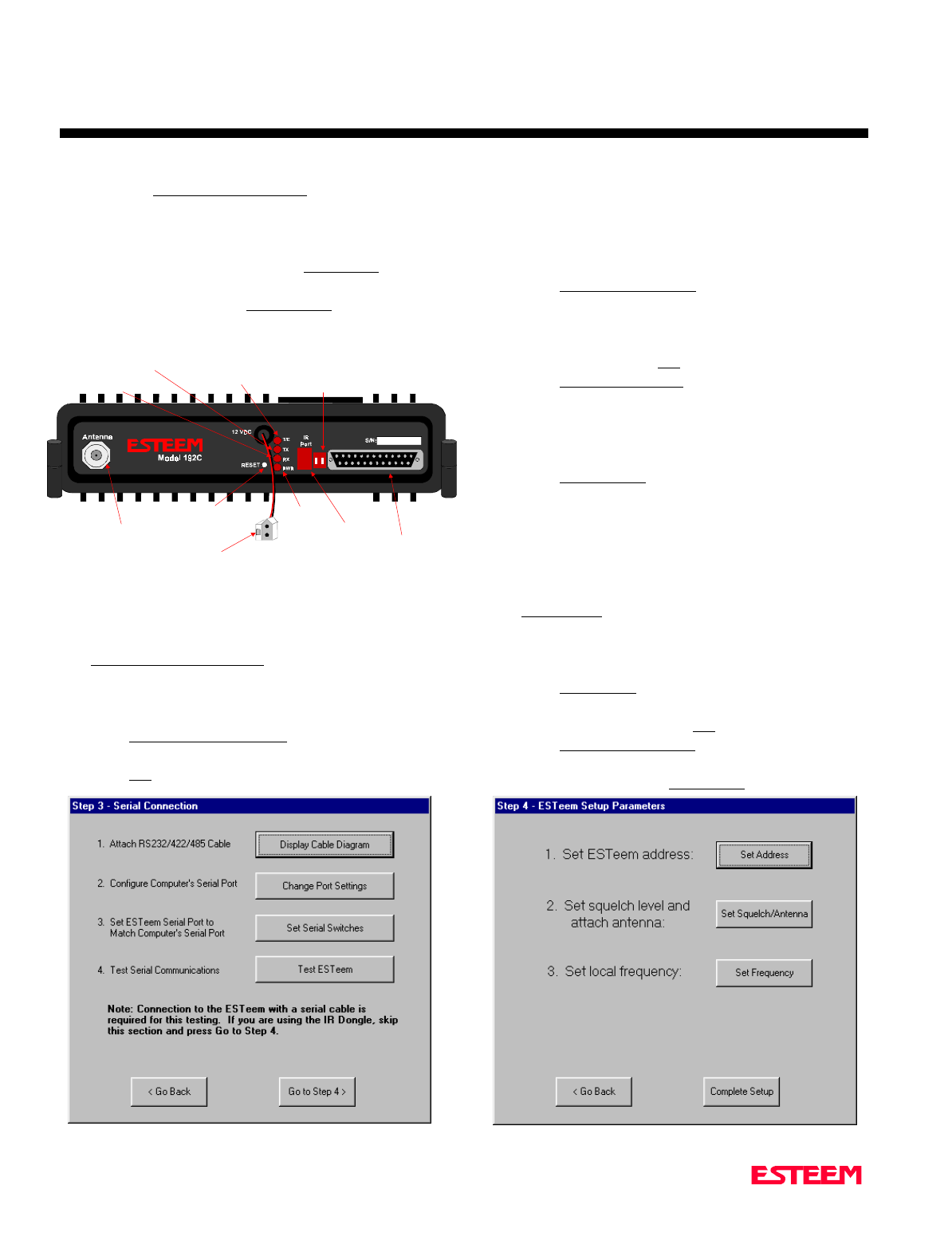
4. Press the Front Panel Description button and a
window containing the ESTeem Model 192 front
panel will appear (Figure 7). Press any one of the
buttons for a complete description of the item’s
function. For example, press the Power LED button
and the description of the power LED and its use
will be displayed. Press Go To Step 3 button to
proceed.
5. Step 3 – Serial Connection window will be displayed
(Figure 8). This step will help configure the
computer and the ESTeem to communicate with
each other.
6. Press Display Cable Diagrams button and all serial
pins to the ESTeem Model 192 will be displayed.
Press OK to continue.
Note: A standard 9-Pin serial port on a computer to
ESTeem interface cable is the ESTeem AA061
(Figure 1).
7. Press Change Port Settings. This window will
configure the communications port on your computer
to operate with the ESTeem modem. Select the
operating parameters you wish or set to the default of
19,200,N,8,1. Click OK to continue.
8. Press Set Serial Switches button. This window will
configure the ESTeem’s RS-232/422/485 to operate
at the setting selected in step 7 to match the
computer port setting. Follow the on-line guide to
configure the data rate.
9. Press Test ESTeem button. If the ESTeem serial
interface cable and communication port are
operating correctly the ESTeem Welcome Message
will be displayed. This will confirm communication
between the computer and the ESTeem. If you do
not receive a welcome message, follow the on-screen
troubleshooting guide that will be displayed. Press
Go to Step 4 button to proceed.
10. Step 4 – ESTeem Setup Parameters window will be
displayed (Figure 9). This step will complete the
setup for your ESTeem Model 192.
11. Press Set Address button. You must give each
ESTeem a unique address in the system. Type in the
address number and press OK to continue.
12. Press Set Squelch/Antenna button. This section will
give you instructions on antenna placement and
installation. Press the Set Squelch button and follow
Figure 8: Step 3 – Serial Connection
Antenna Connector
(
TNC-R
)
12 VDC Input
Power Connector
(
2 Pin Molex
)
Reset Switch
RS-232, 422 and 485
Input/Output Connector
(
25 Pin DB Connector
)
RS-232/422/485
Setup Switches
Power LED
IR Port
Transmit LED
Receive LED
T/E LED
•Link Connect/Disconnect
•Auto Connect Enable
•Serial Port Framing Error
Figure 7: ESTeem Front Panel
Figure 9: Step 4 – ESTeem Setup Parameters
CHAPTER 1
STARTING OUT
Revised: 27 Mar 01 1-5
the on-line guide to configure the ESTeem squelch.
Press OK to continue.
13. Press Set Frequency button. Select the operating
frequency for your ESTeem Model 192 and press Set
Frequency to continue. Set all ESTeems to the same
frequency for operation within this section.
14. Press Complete Setup. You have just configured all
operating parameters within the ESTeem. If this is
your first ESTeem you have programmed for testing,
press the Express Setup button on the Staring Out
Menu (Figure 4) to program subsequent ESTeem
Modems. The Express Setup will allow you to
quickly configure the remaining ESTeem modems
without additional instruction. If you have at least
two ESTeems programmed and wish to test
communication, proceed to step 17.
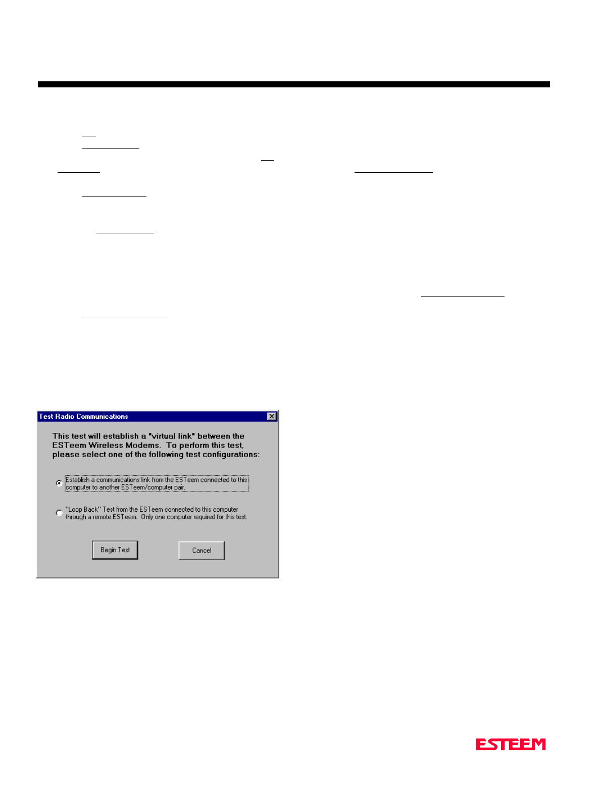
15. Press Test Communication button. This section will
allow you to test the radio frequency (RF)
communications between two or more ESTeems.
Two types of tests are listed in this window (Figure
10). If you have a computer attached to both
ESTeems proceed to step 18 and if you only have
one computer to test both ESTeems proceed to step
19.
16. The first test will be used if you have a computer
attached to both ESTeems. Select the first of two
items and press ENTER. Follow the instructions on
the screen to establish a communication link between
modems.
17. This second test will allow you to use the remote
ESTeem as a digi-repeater for your local modem.
This procedure is explained in the window and can
test communication with only one computer.
18. You now have completed the basic programming
and setup of your ESTeem modems. You have tested
their operation with each other and are now ready to
proceed in programming them for your application.
Press Exit to Main Menu and continue with the
programming of the ESTeem for your application.
BASIC ESTEEM PROGRAMMING
Most of the ESTeem commands outlined in this section
have been automatically input to the modem by the
ESTeem Utility program. A few of the commands used
most often in troubleshooting and programming are
covered here. These commands can be programmed to
the modem directly by the Terminal Emulation section of
the utility or by any other terminal software package.
HELP Functions
The ESTeem has over eighty software commands to aid
the user in their application. The HELP command allow
the user to list the various software commands and their
respective values.
From the COMMAND mode, type HELP<cr>. Your
display should list the following:
Help switches are:
ALL (Lists all settings).
CHANGE (List settings changed from factory default).
CONTROL (List settings dealing with control).
PLC (List settings for PLCs).
RADIO (List settings for ESTeem radio).
RS232 (List settings for RS-232/422/485)
SETUP (List settings for control).
SYSTEM (List settings for system).
These are the different software categories.
Example: HELP SETUP<cr>, will list all the
programmable variables and their settings for the SETUP
category.
You can interrogate a discrete software command by just
typing the command followed by a <cr>.
Example: ADD<cr>, will list the current address saved
in the connected ESTeem.
Figure 10: Test Radio Communication

CHAPTER 1
STARTING OUT
Revised: 27 Mar 01 1-6
Note Appendix E of this manual will have the
complete listing of software commands and
categories for the factory default of the
ESTeem.
Saving A Program
A program is saved by typing in the SAVE command at
the CMD: prompt. The programming variables that have
been changed will be written to the non-volatile memory.
The programming parameters will be loaded each time
the modem is powered up or reset.
Restoring Factory Defaults
The ESTeem has a very simple procedure to restore the
program variables in the unit to the factory default
setting. When the FA<cr> command is entered from the
command mode the ESTeem will be configured from a
variable table located in its EPROM. It is a good practice
to restore the ESTeem to a factory defaults before any
programming of the unit.
To ensure the modem is in the COMMAND MODE set it
back to the factory default by performing the following:
1. Set both switches (#1&2) on the RS-232 setup
switches to the OFF position.
2. Reset the ESTeem.
3. Verify the computer's Comm port is configured for
19,200,N,8,1.
4. Type FA<cr> and the ESTeem welcome message
should be displayed. The characters may not be
echoed on the screen.
5. Type SA<cr> to save the factory default table.


CHAPTER 2
MODES OF OPERATION
Revised: 27 March 01 2-2
The ESTeem has three major modes of operation,
Command, Converse, and Transparent. This chapter of
the manual describes each one of these modes.
COMMAND MODE
The COMMAND Mode (CMD: prompt) is the default
mode that the ESTeem initially enters on power-up or
after a hardware or software reset. From this mode the
user can command or program the ESTeem. In this
mode the user may access the various program
commands to configure the ESTeem for the specific
application. These values can be stored in nonvolatile
memory within the ESTeem by the use of the SAVE
command. The ESTeem reads these setup parameters
stored in memory on power-up or RESET.
When programming in the COMMAND Mode, the user
need only enter enough characters to uniquely identify
the respective command.
Example: CMD:ADD 15 <Enter>
This enters the source address of the ESTeem to the
decimal value of 15. The first three letters ADD were
enough for the ESTeem to uniquely identify the
command for ADDress. The number of characters that
need to be typed varies depending upon the command
being entered. In some cases, four or even more letters
may have to be entered in order for the identification to
be uniquely determined. Up to ten multiple commands
can be written on the same line if separated by a colon.
Example: CMD:ADD 15:SETC 2:SAVE <Enter>
CONVERSE MODE
This mode allows bi-directional communication from the
input/output device attached to the ESTeem to a
destination ESTeem and its respective input/output
device. The ESTeem will automatically switch to the
CONVERSE Mode after the initial CONNECT has been
made.
When the ESTeem is in the CONVERSE Mode the *
prompt will be displayed. The ESTeem will remain in
the CONVERSE Mode until the radio link has been
broken or by typing a control character defined by the
user with the COMMAND variable.
The factory default for the COMMAND variable is
CTRL C. You can return to the CONVERSE Mode from
the COMMAND Mode by typing CONV <Enter>.
When you are in the CONVERSE Mode the echoing of
the character comes from the ESTeem if ECHO = ON
(factory default) has been programmed in the ESTeem.
Transmitting Data
The ESTeem will transmit data from the CONVERSE
Mode if one or more of the following conditions have
been met.
1. The ESTeem transmit buffer has been filled. The
size of the transmit buffer is defined in the ESTeem
by the PACKLEN variable. This variable is
programmable from 1 to 2000 bytes. Factory default
is 2000.
2. The ESTeem receives a SENDPAC (send packet)
character from the RS-232C input data stream. The
SENDPAC variable can be defined from 0 to 255 by
the user. Factory default is 13 (carriage return). The
SENDPAC character is also transmitted by the
ESTeem. In file dump applications the SENDPAC
character can be programmed to be the EOF (end of
file) character transmitted from the sending device
(i.e.; CTRL Z, CTRL G, etc.).
3. Termination control timer. The termination control
timer is enabled by the TERMC (on/off) command.
When enabled, the termination timer starts from the
time the last transmit buffer has been updated in the
RS-232C port. If the termination timer expires
before another character is received or transmitted,
the contents of the ESTeem transmit buffer will be
transmitted. The waiting time of the timer is defined
by the TERMT variable (termination time). The
programming range of the TERMT variable is
10-65,535ms. Factory default values are TERMC =
OFF and TERMT = 50. It is noted that when the
termination timer is used, the SENDPAC variable is
usually programmed to be a character that is non
occurring in your data stream (i.e.; SENDPAC =
255) so that premature transmission does not occur.

CHAPTER 2
MODES OF OPERATION
Revised: 27 March 01 2-3
TRANSPARENT MODE
The TRANSPARENT Mode allows the ESTeem to pass
all data characters (O-255 or 0-FF hex) using 8 data bits.
To program the ESTeem in the TRANSPARENT mode
the TRANSPARent command must be enabled and
switch Bit 2 to ON (RS-232C Setup Switch). The
TRANSPARent command will defeat the SENDPAC and
COMMAND variables and put the ESTeem in the
transparent mode when Bit 2 is ON.
The transmission of the data packets can only be
accomplished by enabling the termination control
commands (TERMC and TERMT) or the PACKLEN
buffer being filled. The value of TERMT should be
slightly longer than the maximum delay encountered
during RS-232C transmission. If this time is set to short,
the ESTeem will truncate your data stream improperly.
When using the TRANSPARENT Mode, data flow
control is by hardware handshaking only. Hardware
handshaking is initiated by enabling hardware flow
control (XHF = ON).
The SETCON (Set Connect command) must be used to
define the node that you want to communicate with while
in the TRANSPARENT Mode. When the
TRANSPARENT Mode is enabled you can not
communicate to the ESTeem in the COMMAND Mode
unless you use the Hardware Mode Control line (see
explanation this chapter).
To remove the ESTeem from the TRANSPARENT Mode
the user must perform the following:
1. Switch Bit 2, Off on the RS-232C Setup Switch.
2. Reset the ESTeem from the front panel switch.
3. Type TRANS OFF <Enter>.
SEMI-TRANSPARENT MODE
This mode should be utilized when sending a non-ASCII
file and there is a possibility that the SENDPAC
character could be contained in the transmitted data set.
Perform the following prior to programming the ESTeem
to initialize the unit to factory default settings:
1. Turn Bit 2, OFF on the RS-232C Setup Switch.
2. Reset the ESTeem.
3. TYPE FA <Enter>. Please note the characters may
or may not be echoed by the CRT.
ESTeem
-------------------------
ADD xxx xxx = your address
SETC yyy yyy = destination address
TERMC ON
TERMT 10
SENDP 255
EDIT OFF
XSF ON
SAVE
If EDIT is off, and SENDPAC = 255, the SENDPAC
character is disabled. This character when received will
not cause packet transmission and will be passed as
normal data. The TERMC and TERMT commands are
used to transmit the contents of the ESTeem transmit
buffer.
Software flow control in this example is enabled (factory
default XSF = OFF) therefore the ESTeem will pass all
characters except the data flow control characters for
Xon/Xoff.
HARDWARE MODE CONTROL
The MODECON (Mode Control) command is provided
in the ESTeem to change the mode of the ESTeem
modem from COMMAND Mode to CONVERSE (or
TRANSPARENT Mode) via a hardware control line.
The hardware line is located on pin 19 of the RS-232C
connector. If MODEC = HARDWARE, a "low or 0" on
pin 19 (-3 to -15 vdc) will put the ESTeem in the
COMMAND Mode and a "high or one" on pin 19 ( +3 to
+15 vdc) will put the ESTeem in the CONVERSE or
TRANSPARENT Mode. The factory default is
SOFTWARE.


CHAPTER 3
PROGRAMMING ESTEEM FEATURES
Revised: 27 March 01 3-2
Listed in this chapter are the major ESTeem features and
programming examples on how to use them. These
features are individual building blocks to solve your
application needs. Remember your particular application
may require one or more of these features enabled.
DIGI-REPEATING
The Repeater feature allows an ESTeem to relay it's
respective transmission or packet through a maximum of
three ESTeems to increase the operating range of the
unit. Any ESTeem in your radio network can function as
a repeater for any other ESTeem. This is independent of
the fact that the ESTeem being used as a repeater is
linked or connected to another node, therefore an
ESTeem can function as a repeater, operational node, or
both at the same time. The data that is digi-repeated
through an ESTeem will not be output through the
repeating ESTeem’s RS-232C port.
To specify one or more ESTeems as repeaters, the
CONNECT command has been expanded to except up to
three added addresses as follows:
CONN r1,r2,r3,da
r1 = Address (1 to 254) of first ESTeem repeater.
r2 = Address (1 to 254) of second ESTeem repeater.
r3 = Address (1 to 254) of third ESTeem repeater.
Da = Address (1 to 255) of destination ESTeem.
Note: Address 255 is used for Global.
When transmitting packets through other ESTeems, the
source ESTeem will automatically adjust it's FRACK
time to allow additional time for the packet to reach its
destination and for the returned acknowledgment. Frack
time takes into account the packet size and the number of
repeaters specified. The ACK still comes from the
destination ESTeem, not the first or any repeater.
For testing purposes, you can loop back a connection to
yourself by placing your source address in the destination
address of the repeater string. Any data transmitted will
repeat through the repeater address and display back on
the screen.
Example:
CONN r1,Sa
r1 = Address (1 to 254) of first ESTeem repeater.
Sa = Address of local ESTeem.
Any ESTeem command in this manual that uses an
address string can be configured to use the Digi-
repeating feature.
Example:
SETC r1,r2,r3,da
GLOBAL BROADCAST
Global broadcast is the ability of one ESTeem to transmit
it's message to more than one ESTeem at one time. All
ESTeems within radio range will receive the message
whether or not they are connected to another ESTeem or
in command or converse mode.
You can put your ESTeem in Global by connecting or
programming the SETC to address 255. Address 255 is
a non assignable unit address and is used by the ESTeem
CPU to access this special mode. When an ESTeem is in
Global, the standard ACK protocol from the receiving
ESTeem is disabled, but the 32 bit CRC error checking
on the received ESTeem is still operational. When you
perform CONN 255 <Enter> from the COMMAND
MODE the ESTeem will immediately go to the
CONVERSE MODE (* is displayed). All messages sent
will be transmitted globally to all ESTeems in radio
range.
In the ESTeem you have a GLOBAL (on/off) command.
When GLOBAL = On, you can receive Global
transmissions. If GLOBAL = Off you will not display
Global transmissions from other ESTeems.
Note: Factory default is ON.
By using the repeater function you can transmit Global
messages from another ESTeem using the Digi-repeating
feature.

CHAPTER 3
PROGRAMMING ESTEEM FEATURES
Revised: 27 March 01 3-3
Example:
CONN 10,20,30,255<Enter>
SETC 10,20,30,255<Enter>
By adjusting these commands you can route from unit 10
to 20, 20 to 30, and go Global at unit 30.
You can enable global transmissions in more than one
ESTeem in your network. This will allow global
communications between all ESTeems within radio
range.
AUTO TRANSMIT
The Auto Transmit feature of the ESTeem allows the
user to transmit a data packet without filling up the
PACKLEN (packet length) buffer or defining a special
control character using the SENDPAC (send packet)
variable. The Auto Transmit feature is a timer that is
enabled in the ESTeem that monitors traffic in and out of
the RS-232C port. If there are characters in the RS-232C
buffer, the termination control timer starts from the time
the last receive or transmitted character is updated in the
buffer. If the termination time expires before another
character is received or transmitted, the received
characters are transmitted.
To enable this feature perform the following from the
COMMAND MODE:
TERMC (on/off) = On. Enable termination control.
TERMT (10-65535) = One unit number equals 1ms.
TERMC is the termination control command. TERMT
is the termination time command. Factory default for
TERMC = Off and TERMT = 50.
AUTO CONNECT
The Auto Connect feature allows the user to program the
ESTeem to perform a CONNECT to another ESTeem
when data is sent to the RS-232C communications port.
To enable this feature perform the following from the
COMMAND MODE:
SETCON (1-255) = Address of destination ESTeem.
Remember, you can use the Repeater routing
(r1,r2,r3,da) or put the ESTeem in Global (address 255).
SETCON is the set connect command.
SA SAVE command. This will save the SETC
variable to the non volatile memory so that it
will not be lost when the ESTeem is RESET.
Bit 2 (on/off) = On. Bit 2 is located on the RS-232C
SETUP SWITCH on the front of the
ESTeem. The ESTeem must be
RESET after the Bit has been changed
to be read by the ESTeem CPU.
RESET ESTeem RESET is located on the front panel
OFF/ON switch. The T/E light on the
front panel of the ESTeem should now
flash at a two times per second rate.
MULTI-CONNECT
The actual polling of the ESTeem must originate from
the host device connected to the ESTeem using the
CONNECT command to originate the initial connect and
the COMMAND character to return from the
CONVERSE mode to the COMMAND mode. The first
time around the pole a CONNECT data packet (rf
transmission) will be initiated. When a link is
established, it is held internally in the ESTeem connect
table. The next time around the pole to the same address,
the link status will be checked in the ESTeem table. If
the address indicates a link has already been established,
then only data and its corresponding ACK will be
transmitted to that node. This greatly increases polling
time by eliminating the usual
CONNECT/DISCONNECT sequence each time except
when communication is first established.
The MULTID command allows the user to send data to a
specific ESTeem address from the CONVERSE Mode by
specifying the ESTeem address routing before the data
packet. This feature will also display the address of the
sending ESTeem on any received data.

CHAPTER 3
PROGRAMMING ESTEEM FEATURES
Revised: 27 March 01 3-4
Example Of Transmitted Data:
[001]DATA Routes data to an ESTeem addressed 1.
[100,200,250,1]DATA Routes data to an ESTeem
addressed 1 via ESTeems
addressed 100, 200, and 250.
The above example replaces the CONNECT command
from the COMMAND Mode.
Received data packets will have the address of the
ESTeem that sent the data at the beginning of the data
packet.
Example Of Received Data:
[004]RECEIVED DATA Data received from an
ESTeem addressed 4.
[030,100,244,004] Data received from an ESTeem
addressed 4 via ESTeems
addressed 30, 100, and 244.
MULTID (on/off) = On Enables this feature. Factory
default = OFF.
REMOTE PROGRAMMING
The Remote Programming feature allows the user to
remotely program ESTeems in his network. When a
connection has been made with the remote ESTeem the
RPG: prompt will be displayed showing that you are now
in the COMMAND mode of that remote ESTeem.
To enable this feature perform the following from the
COMMAND MODE:
PROG (1-254) Address of destination ESTeem.
Note: You can also use the Repeater routing
(r1,r2,r3,da) to reach the destination ESTeem.
(r1 = address of first repeater, r2 = address of
second repeater, etc. da = destination address).
To end a remote programming session, hold Control and
type C (^C) and you will return to the COMMAND
prompt of your ESTeem. There is a Watch Dog Timer
that will automatically disconnect you from remote
programming if there is no activity for thirty seconds.
The REMPROG (on/off) feature is used to defeat the
ability of your ESTeem from being remotely
programmed. If REMPROG = OFF another ESTeem
cannot remotely program your unit. Factory default =
ON.
SECURITY
The Security feature allows the user to lock out
programming of the ESTeem. REMEMBER TO STORE
YOUR CODE NUMBER IN A SAFE PLACE.
To enable this feature perform the following from the
COMMAND MODE:
SECURITY (1 to 100,000) Entering a security
number enables the
security feature.
SAVE To enter the security code permanently into the
ESTeem memory.
Note: When enabled, the ESTeem will output a
“Security On” message.
To disable the security feature perform the following
from the COMMAND mode.
SECURITY (1 to 100,000) Entering your security
number disables the
security feature.
SAVE To remove the security code permanently from
the ESTeem memory.
Note: When disabled, the ESTeem will output a
“Security Off” message.
CHAPTER 3
PROGRAMMING ESTEEM FEATURES
Revised: 27 March 01 3-5
HARDWARE RING LINE (Factory Option)
When the ESTeem establishes a CONNECT or link with
another ESTeem (T/E Light on solid), pin 22 at the
ESTeem RS-232C will change from a -15 vdc voltage
state to a +15 vdc voltage state. The RING software
command allows the user to change the output from a
latched state to a pulsed state. To change the state of this
line program the following from the COMMAND mode.
Factory default = LATCH.
RING =Latch. Pin 22 is high when the ESTeem T/E
light is on solid.
RING =Pulse. Pin 22 is pulsed (positive 250 ms.) when
the ESTeem T/E light is on solid.
PACKET MONITOR
The PACKM [ON/OFF] command places the ESTeem in
a special packet monitor mode. When this feature is
enabled the ESTeem is placed in a receive only mode and
will not function as a normal ESTeem. The ESTeem will
monitor and report the status of all message traffic within
the network in the following format, the actual packet
message will not be outputted.
SA-xxx, DA-xxx, Type Code, R1-Repeater Status, R2-
Repeater Status, R3-Repeater Status, Data Bytes Sent
xxx = ESTeem Address
DA = Destination ESTeem
SA = Source ESTeem
R1 = Address of first ESTeem repeater.
R2 = Address of second ESTeem repeater.
R3 = Address of third ESTeem repeater.
Type Codes
I = Information
DISC = Disconnected
RR = Receive Ready
UA = Unnumbered Acknowledge
RNR = Receive Not Ready
FRMR = Frame Reject
REJ = Reject
DM = Disconnected Mode
UI = Unnumbered Information
SABM = Set Async. Balance Mode
Repeater Status
P=Pending
D= Done
USING THE INFRARED
COMMUNICATIONS PORT
The infrared (IR) communications port will allow you to
program and interrogate the ESTeem without
disconnecting the serial cable from the back of the
modem. The IR port is located on the front panel of the
ESTeem, above the T/E light.
To communicate from a computer to the ESTeem
through the IR port you will need a copy of the ESTeem
Utilities (Version 4.0 or higher) and an ESTeem IR
Communication Dongle (ESTeem P/N AA300).
Connect the dongle directly to the serial port of the
computer. The dongle requires initialization from the
ESTeem Utilities. From the Terminal Emulation screen
press the F3 function key to initialize the dongle. If the
modem is not in the COMMAND mode, press CTRL-C
to display the CMD: prompt.
Note:With Switch 2 (RS-232 Setup) in the On position
the ESTeem defaults the IR port to the command
mode.
ANTE
NNA
S/N:
T/E
TX
RX
PWR
IR
Port
Phone
Model 192S
Antenna 12 VDC
RESET
Infrared Communications Port for
Remote Programming and Diagnostics
Without Interruption Of The Wireless
Radio Area Network
IR Communications Dongal
(EST p/n AA300)
3 ft. Range
RE
SET
Figure 1: Using The IR Port
CHAPTER 3
PROGRAMMING ESTEEM FEATURES
Revised: 27 March 01 3-6
The IR dongle has a range of approximately three feet,
directly in front of the port. The dongle is powered by
the serial port and requires no additional power sources.
Note: Only one of the three communications ports
(RS-232/422/485 connector, IR port or Remote
Programming) can be in the Command mode at
a time. When either the IR or the Phone port
switch to converse mode, the RS-232/422/485
port is blocked from receiving any data.
UPDATING FLASH MEMORY
The ESTeem Model 192 stores its operating system in
flash memory that can be updated without returning the
modem the to the factory. To upload the latest operating
file, please contact Customer Support at 509-735-9092 or
e-mail support@esteem.com to request the latest flash
memory update file for your product.
Once you receive the flash file from Customer Support,
conduct the following steps to update the memory:
1. Open the ESTeem Utilities and select Terminal
Emulation.
2. Verify that both switches (Bits 1 and 2) are in the
down (OFF) position and reset the modem.
3. Select Terminal Setup>Port from the menu items
and configure the computer serial port for
19,200,N,8,1.
Note: The flash update can not be loaded through the
Infrared Dongle or remote programming. You must
connect directly the ESTeem serial port.
4. Set the modem to factory defaults by entering FA
<Enter> at the command prompt (CMD:).
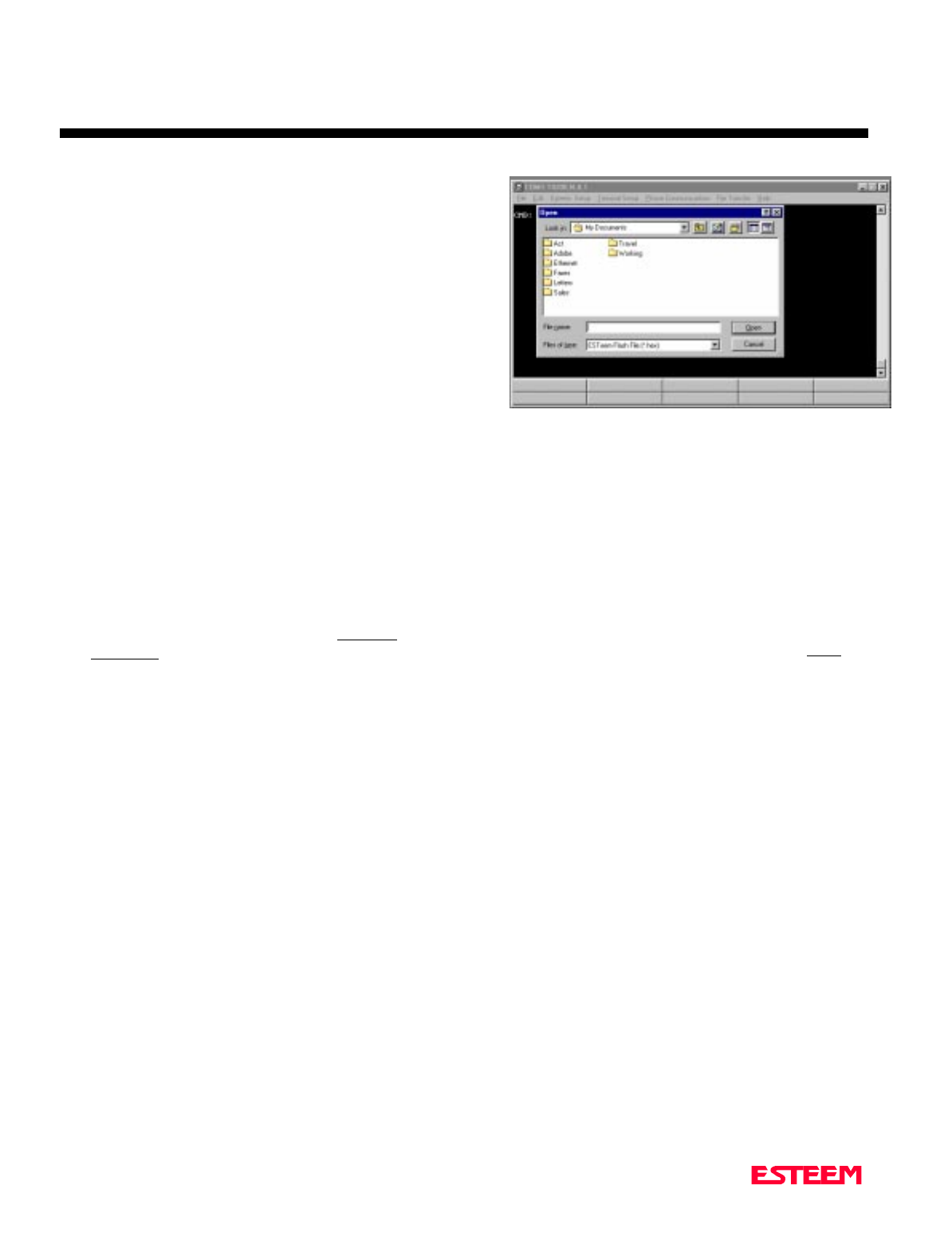
5. Select ESTeem Setup>Update Flash Memory from
the menu and the Utility will read information about
the connected modem and ask for the location of the
flash file (Figure 2). Browse to the location of the
flash update file on the computer and select Open.
6. Once the upload has been completed, re-program the
modem for operation.
Figure 2: Updating Flash Memory


CHAPTER 4
ESTEEM APPLICATION PROGRAMS
Revised: 27 March 01 4-2
Listed below are different application programs to aid the
user in programming the ESTeem.
TRANSPARENT AUTO-CONNECT
This mode is used for a dedicated point to point
application. The ESTeem will initiate the radio link
when data is received by the RS-232/422/485 port.
Perform the following prior to programming the
ESTeem(s) to initialize the unit to factory default
settings:
1. Turn Bit 2 OFF on the RS-232C Setup Switch.
2. Reset the ESTeem.
3. TYPE FA <Enter>. Please note the characters may
not be echoed by the CRT.
ESTeem A ESTeem B
------------------------------ --------------------------------
ADD xxx ADD yyy
SETC yyy SETC xxx
TERMC ON TERMC ON
TERMT 10 TERMT 10
XHF ON * XHF ON *
DISACK ON * DISACK ON *
TRANS ON TRANS ON
SAVE SAVE
Bit 2 ON Bit 2 ON (RS-232 Switch)
Reset ESTeem Reset ESTeem
Notes:
• Turn DISACK ON only if you want to defeat the
acknowledge packet.
• xxx and yyy represent an ESTeem address which is
user definable from 1 to 254.
TRANSPARENT AUTO-CONNECT
GLOBAL
This mode is usually used for a point to multi-point
applications when a customers devices include their own
addressing protocol to communicate between devices.
The ESTeem packet addressing and acknowledge
protocol is defeated. All ESTeems will receive the data
transmission. The 32 bit CRC error checking on
received data is still enabled. This program is used in all
ESTeems, the only difference is the unit addresses.
Perform the following prior to programming the
ESTeem(s) to initialize the unit to factory default
settings:
1. Turn Bit 2 OFF on the RS-232C Setup Switch
2. Reset the ESTeem.
3. TYPE FA <Enter>. Please note the characters may
not be echoed by the crt.
ESTeem A
----------------------------------------------------
ADD xxx (xxx = ESTeem address)
SETCON 255
TERMC ON
TERMT 10
XHF ON *
TRANS ON
SAVE
Bit 2 ON (RS-232 Switch)
Reset ESTeem
Note:Only hardware flow control can be used in this
mode.

CHAPTER 4
ESTEEM APPLICATION PROGRAMS
Revised: 27 March 01 4-3
INTERACTIVE TERMINAL APPLICATION
This program is used to connect a mainframe to a remote
terminal. This setup is a typical point to point
configuration with the AUTO-CONNECT feature
enabled.
Perform the following prior to programming the
ESTeem(s) to initialize the unit to factory default
settings:
1. Turn Bit 2 OFF on the RS-232C Setup Switch.
2. Reset the ESTeem.
3. TYPE FA <Enter>. Please note the characters my
not be echoed by the crt.
ESTeem At Mainframe ESTeem At Terminal
-------------------------- ------------------------
ADD xxx ADD yyy
SETC yyy SETC xxx
TERMC ON TERMC ON
TERMT 10 TERMT 10
XSF OFF XSF OFF
XHF ON * XHF ON *
DISACK ON * DISACK ON *
TRANS ON TRANS ON
SAVE SAVE
Bit 2 ON Bit 2 ON (RS-232 Switch)
RESET ESTeem RESET ESTeem
Notes:
• Turn DISACK ON only if you want to defeat the
acknowledge packet.
• Only hardware flow control can be used in this
mode.
• xxx and yyy represent an ESTeem address which is
user definable from 1 to 254.
PROGRAMMABLE LOGIC CONTROLLERS
EST has available complete Engineering Reports for each
PLC manufacturer make which will be provided at no
charge by calling EST Customer Support on
509-735-9092. All Engineering Reports are also
available on the ESTeem Utility Software CD (EST P/N
AA106) in Adobe™ PDF format.


CHAPTER 5
RS-232C/422/485 INTERFACING
Revised: 27 Mar 01 5-2
DTE vs. DCE
The ESTeem is configured as a Data Communication
Equipment (DCE) device. The following signals are
available at the RS-232C connector located at the rear of
the unit.
Pin Description
---------------------------------------------------------------------
1 FG Shield Ground
2 TXD Transmit Data (Input)
3 RXD Receive Data (Output)
DCE 4 RTS Request To Send (Input)
5 CTS Clear to Send (Output)
7 SG Signal Ground
8 DCD Data Carrier Detect (Output)
12 RTS Request To Send (Output)
20 DTR Data Terminal Ready (Input)
22 Ring Ring Indicator (Output)
The important thing to remember is that for the ESTeem
to communicate with an external device, the data output
from pin 3 of the ESTeem RS-232C connector must be
connected to the data input of the device you are
connected to; otherwise, the ESTeem won't work.
Likewise, the data input to pin 2 of the ESTeem must be
connected to the data output of the device you are
connected to. Normally, if the equipment you are
connecting to looks like a terminal or computer (DTE),
its input, Receive Data (RXD), will be on pin 3 its
output, Transmit Data (TXD), will be on pin 2.
Therefore, the ESTeem can be connected directly.
If the device you are connecting to is configured as a
modem (DCE), its output will be on pin 3. If this
configuration is connected to the ESTeem, damage may
result to the ESTeem or the connecting device. In this
case, you can purchase a null connector that internally
reverses pins 2 and 3.
Whatever your situation may be, it is always best to check
the manual on your particular device and connect
accordingly.
Purchase or fabricate a RS-232C shielded cable for your
ESTeem. The ESTeem requires a standard male 25 pin D
connector on one end of the cable for proper connection.
Remember to install the small retaining screws on either
side of the cable connector. Tightening these screws
keeps you from accidentally losing connection with your
ESTeem.
Notes:
• The ESTeem requires a shielded RS-232 cable. This
is to prevent unwanted electrical noise from entering
the ESTeem and also to prevent any electrical noise
from getting out of the ESTeem.
• Remember -- always use a shielded RS-232C cable.
• Pins 9, 10, 14, & 16 are used for RS-422/485
interfacing and should be left open if not used.
FLOW CONTROL
The ESTeem can be enabled to support SOFTWARE or
HARDWARE flow control.
Software Flow Control
Software flow control is enabled by the XSFLOW
(on/off) command in the ESTeem. When XSFLOW is
ON the ESTeem will respond to <XOFF>, (stop) and
<XON>, (off) commands from the RS-232 port. The
factory default setting is OFF. The default value for
START is 17 (CTRL Q) and for STOP is 19 (CTRL S).
Hardware Flow Control
Hardware flow control is enabled by the XHFLOW
(on/off) command in the ESTeem. The factory default
value is OFF.
When XHFLOW is enabled (on) the control signal lines,
Request To Send (RTS, pin 4), Data Carrier Detect
(DCD, pin 8), and Clear To Send (CTS, pin 5) are
available to the user at the RS-232C connector. The CTS
and RTS signals are used to control the flow of data into
and out of the ESTeem.
The CTS signal on pin 5 is used to control the data into
the ESTeem. When CTS is set (high on pin 5) the
modem is ready to receive data. When CTS is reset (low
on pin 5) the ESTeem is not ready to receive data.
The RTS signal is used to control data out of the
ESTeem. RTS is set (high on pin 4), by the user to
indicate to the ESTeem that the user is ready to receive
data. When reset, the user is not ready to receive data.
(NOTE: Low = On, High = Off).

CHAPTER 5
RS-232C/422/485 INTERFACING
Revised: 27 Mar 01 5-3
MEMORY BUFFERS
The ESTeem has a 4000 byte buffer on the TRANSMIT
SIDE (outgoing data) and a 4000 byte buffer on the
RECEIVE SIDE (incoming data).
Transmit Buffer
The outgoing data buffer will hold two data blocks before
the ESTeem will enable its RS-232C hardware/software
flow control on data coming into the modem if the
network is busy. A data block in this example is a block
of data that is defined by the PACKLENGTH or
SENDPAC character which ever occurs first.
Therefore, if PACKLENGTH = 10 the modem will input
a maximum of 20 bytes before it enables its
hardware/software handshake line (two 10 byte packets).
In another example, if PACKLENGTH = 2000 but the
data block is terminated by the SENDPAC character
before the input buffer reaches the full 2000 bytes, the
buffer will still hold only two data blocks if the network
is busy.
In order to utilize the 2000 bytes storage for small data
packets (bar code readers, etc.), program the modem
using the following guidelines:
PACKLENGTH = 2000 SENDPAC = 255
TERMC = ON TERMT = 10
Note: Set the TERMT time greater than the pause
between data bursts.
By programming the above parameters the ESTeem will
buffer the incoming data packets and automatically
transmit the data when the 2000 byte buffer is filled or
the TERMT time limit is met. This will allow the
customer to use two blocks of 2000 or 4000 bytes before
the modem enables the respect hardware/software
control.
Receive Buffer
If the device that the receiving ESTeem is outputting data
to, enables its respective hardware or software control,
the modem will store 4000 bytes of data before flow
controlling off the transmitting ESTeem.
DATA TERMINAL READY (DTR)
A software switch, DTR_ENAB (ON/OFF) is provided in
the ESTeem for monitoring the status of a device
connected to pin 20 of the RS-232C connector. The
factory default setting is OFF. When this command is
enabled the ESTeem will monitor the DTR signal on pin
20. If the DTR line being supplied to the ESTeem, from
the user, is at a SPACE (high) condition then the
ESTeem is enabled. If the DTR line is at a MARK (low)
condition then the ESTeem is disabled.
This signal is normally used by the ESTeem modem as
an indication that connection is made to a device that is
on line and ready to transmit/receive data.
RS-422/485 CONFIGURATION
The ESTeem will support the requirements of the EIA
Standard RS-422/485. This is a four (4) wire interface
consisting of the TRANSMIT DATA (-), TRANSMIT
DATA (+), RECEIVE DATA (-), AND RECEIVE
DATA (+) or a two (2) wire interface using B (+) and A
(-). These signals are available at the 25 pin RS-232C
connector on the modem.
Pin Description
9 BTR (-) TRANSMIT DATA (-)
10 BTR (+) TRANSMIT DATA (+)
DCE 14 BRX (+) RECEIVE DATA (+)
(4-Wire) 16 BRX (-) RECEIVE DATA (-)
Pin Description
DCE 14 (+) HALF-DUPLEX B (+)
(2-Wire) 16 (-) HALF-DUPLEX A (-)
This interface is designed to provide unipolar differential
drive to twisted pair or parallel wire transmission lines.
Note: The ESTeem is configured at the factory for
RS-422 interfacing . RS-485 (either 4 or 2 wire
mode) requires internal jumper configuration.
Please contact EST Customer Support at 509-
735-9092 for instruction.
The ESTeem can be factory configured RS-485
interfacing prior to shipment. Call EST
Customer Support on 509-735-9092 for further
details.

CHAPTER 5
RS-232C/422/485 INTERFACING
Revised: 27 Mar 01 5-4
RS-232C/422/485 Configuration Tables
On the front plate of the ESTeem is a two position
RS-232 Setup switch labeled SW. The switch positions
are defined as follows:
RS-232C/422/485
SETUP SWITCH TABLE
BIT 1 OFF Default baud rate 19.2K, N, 8, 1
BIT 1 ON Use software to select baud rate
BIT 2 OFF Enter Command Mode upon
initialization
BIT 2 ON Enter Conversation Mode upon
initialization
Note: *The ESTeem is configured at the factory for
RS-422 interfacing. RS-485 (2 or 4 wire) requires
internal jumper configuration. Please contact EST
Customer Support at 509-735-9092 for instruction
RS-232C/422/485 COMRATE Tables
The ESTeem Model 192 uses the COMRATE software
command to set the communication port speed when Bit
1 on the RS-232 Setup Switches is in the ON position.
The ESTeem Utility Program will calculate the required
COMRATE value and download to the ESTeem in Step
3 of the Starting Out Menu or by selecting ESTeem
Setup>Configure ESTeem Serial Port from the Terminal
Emulation menu. If you would like to manually enter the
command to set the serial port speed on the modem
please use the following table as a guideline:
19,200 9,600 4,800 2,400 1,200 600
0 12345
N,7,1
8 9 10 11 12 13 N,7,2
16 17 18 19 20 21 E,7,1
24 25 26 27 28 29 E,7,2
32 33 34 35 36 37 N,8,1
40 41 42 43 44 45 N,8,2
48 49 50 51 52 53 E,8,1
56 57 58 59 60 61 E,8,2
80 81 82 83 84 85 O,7,1
88 89 90 91 92 93 O,7,2
112 113 114 115 116 117 O,8,1
120 121 122 123 124 125 O,8,2
ESTeem RS-232C/422/485
Port Pin-Out Table
Pin No. Function
1Shield Ground
2Transmit Data (TxD)
3Receive Data (RxD)
4Request To Send (RTS Input)
5Clear To Send (CTS)
6Data Set Ready (DSR)
7Signal Ground
8Data Carrier Detect (DCD)
19 Mode Control
20 Data Terminal Ready (DTR)
22 Ring Indicator (RI)
12 Request To Send (RTS Output)
9* RS-422/485 Transmit Data (-)
10* RS-422/485 Transmit Data (+)
14* RS-422/485 Receive Data (+)
16* RS-422/485 Receive Data (-)
.


CHAPTER 6
ANTENNAS
Revised: 27 Mar 01 6-2
EST offers different types of antennas ranging from 1/4
wave to 5/8 wave in physical size. The user choice is
dependent on the application.
Communications in the VHF and UHF bands are
normally over "Line of Sight (LOS)". Looking from the
antenna of one wireless modem you must be able to see
the antenna of the wireless modem you wish to
communicate with. If a large object obstructs the line of
sight view it is unlikely that satisfactory communications
will result. This means you must relocate the antennas or
use the REPEATER FEATURE and a second modem to
go over or around the object.
The Model 192C/F/M products are allowed by the FCC
to use high gain directional antennas.
It is noted that a 1/4 wave antenna that does not have
ground plane radials requires a ground plane to operate
at maximum efficiency. This can simply be a conducting
surface under the antenna that is a 1/4 wave length in
diameter. For the Model 192C this is approximately 6.5
inches. A conducting surface can be anything from the
roof top of an automobile to a file cabinet.
COAXIAL CABLES
To minimize signal loss, the overall length of the coaxial
cable should be as short as possible. To avoid corrosion
select coaxial cable manufacturers with tinned copper
braid, where possible. Listed below are representative
cable losses in db/100ft at the VHF and UHF frequencies:
Frequency (MHz) RG-58u RG-8 ½” Heliax
---------------------------------------------------------------------
150-174 - 5.2 - 2.3 - 0.845
402-420 -10.0 - 4.2 - 1.5
450-470 -10.8 - 4.4 - 1.5
In a severe noise environment it my be desirable to use a
double shield type of coax cable such as RG-214/U.
Note: Pre-made coax cables can be purchased from
the factory. A -3 dB loss means you have lost
1/2 of your signal. A +3 dB gain means you
have doubled (x2) your signal.
Keep the antenna feedline as short as
possible to minimize losses.
Extreme care must be taken when attaching
coax connectors to the antenna feedlines.
If there is any error in making this
connection the output of the transmitter will
be greatly reduced.
WEATHER PROOFING COAX
CONNECTIONS
1. Coat the threads of the connectors with silicone
lubricant prior to assembly (See Note 1) and hand
tighten. Care should be taken not to get any
lubricant on the center conductor.
2. Wrap the connector assembly with a vapor barrier
patch for weather proofing (See Note 2), ensuring to
overlap onto the coax cable approximately 1 1/2
inches.
3. Apply a electrical coating (sealing agent) over the
vapor barrier patch for added protection (See Note
3).
Notes:
1. Dow Corning RTV-3140 or equivalent.
2. Suggested vendors:
VAPOR-WRAP
Decibel Products
3184 Quebec St.
Dallas, TX 75356
214-631-0310
VYNIL-MASTIC, P/N 2200
3-M Company
Customer Service
512-984-1800
3. SCOTCHKOTE, 3-M Company, or equivalent.
GROUNDING
All building mount antennas require attachment to a
good earth ground for optimum efficiency. Contact a
reputable local communications shop for procedures for
your area.

CHAPTER 6
ANTENNAS
Revised: 27 Mar 01 6-3
LIGHTNING ARRESTORS
Lightning arrestors should be used on all external
building mount antennas for personal protection and to
minimize damage to the transceiver during lightning
storms. The units should be installed as per
manufacturers instructions provided with the device.
REFERENCE MATERIAL
The ideal reference book for antennas and transmission
lines is the “The Radio Amateur's Handbook”, by the
Headquarters Staff of the American Radio Relay League.
CHAPTER 6
ANTENNAS
Revised: 27 Mar 01 6-4
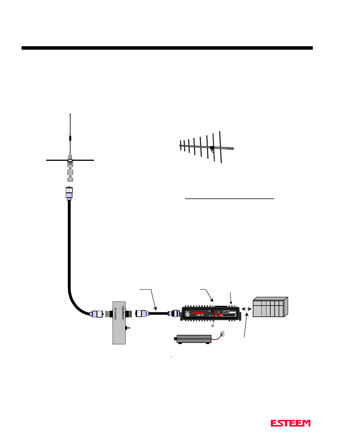
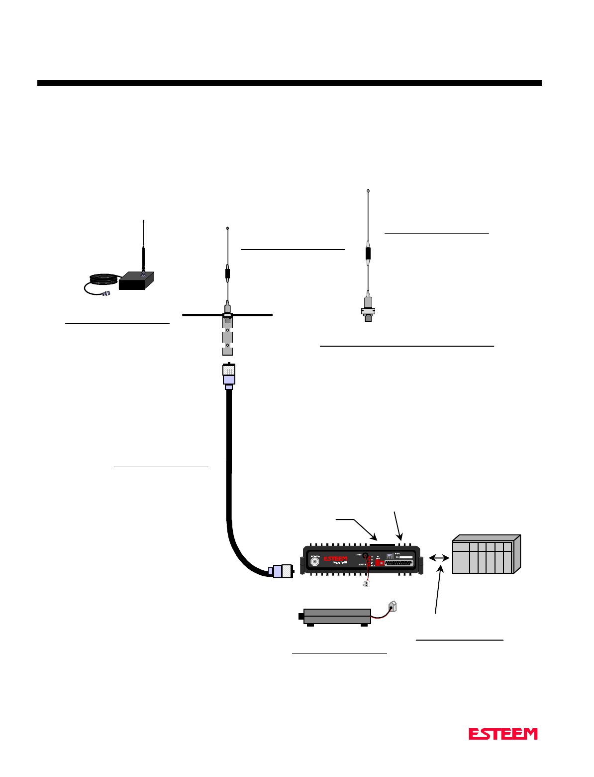
Model 192M Outdoor
Fixed Base Site Diagram
N Male
Connector
N Male
Connector
TNC Male
Connector
2 Pin Molex
Connector
User’s
Device
RG-8 Coax
(EST Part No. AA234
RS-232C
Setup
Switches
RS-232C, 422, & 485
Interface Connector
NOTES
1. Use coax cable runs as short as practical to
minimize cable losses.
2. Vapor wrap all external antenna coax
connections with vin
y
l wrap
(
EST Part No. AA241
)
and appl
y
Scotchkote Electrical Coatin
g
(
EST Part
No. AA242
)
.
3. Contact EST for recommendations re
g
ardin
g
antenna mountin
g
hardware and installation tips.
4. Ground antenna structure, base and li
g
htnin
g
arrestor.
ANTENNA
RECOMMENDATIONS
1. Omni-Directional
(EST P/N AA20M or
ASP682).
2. Directional (EST P/N
AA202M).
Directional
Antenna
Omni-Directional
Antenna
UHF Male
Connector
for AA235
or AA238
ANTENNA FEEDLINE
RECOMMENDATIONS
1. Up to 50 ft. use RG-8
Coax (EST P/N AA235)
or AA237.
2. Over 50 ft. use 1/2”
heliax (EST P/N AA236)
or AA238.
N Male
Connector
for AA236
or AA237
12 VDC Power Supply
(EST Part No. AA174)
RS-232C,422, or 485
Interface Cable
(EST Part No. AA06,
AA061, AA07, or
custom depending on
device)
Lightning Arrestor
(EST Part No. AA162)
CHAPTER 6
ANTENNAS
Revised: 27 Mar 01 6-5
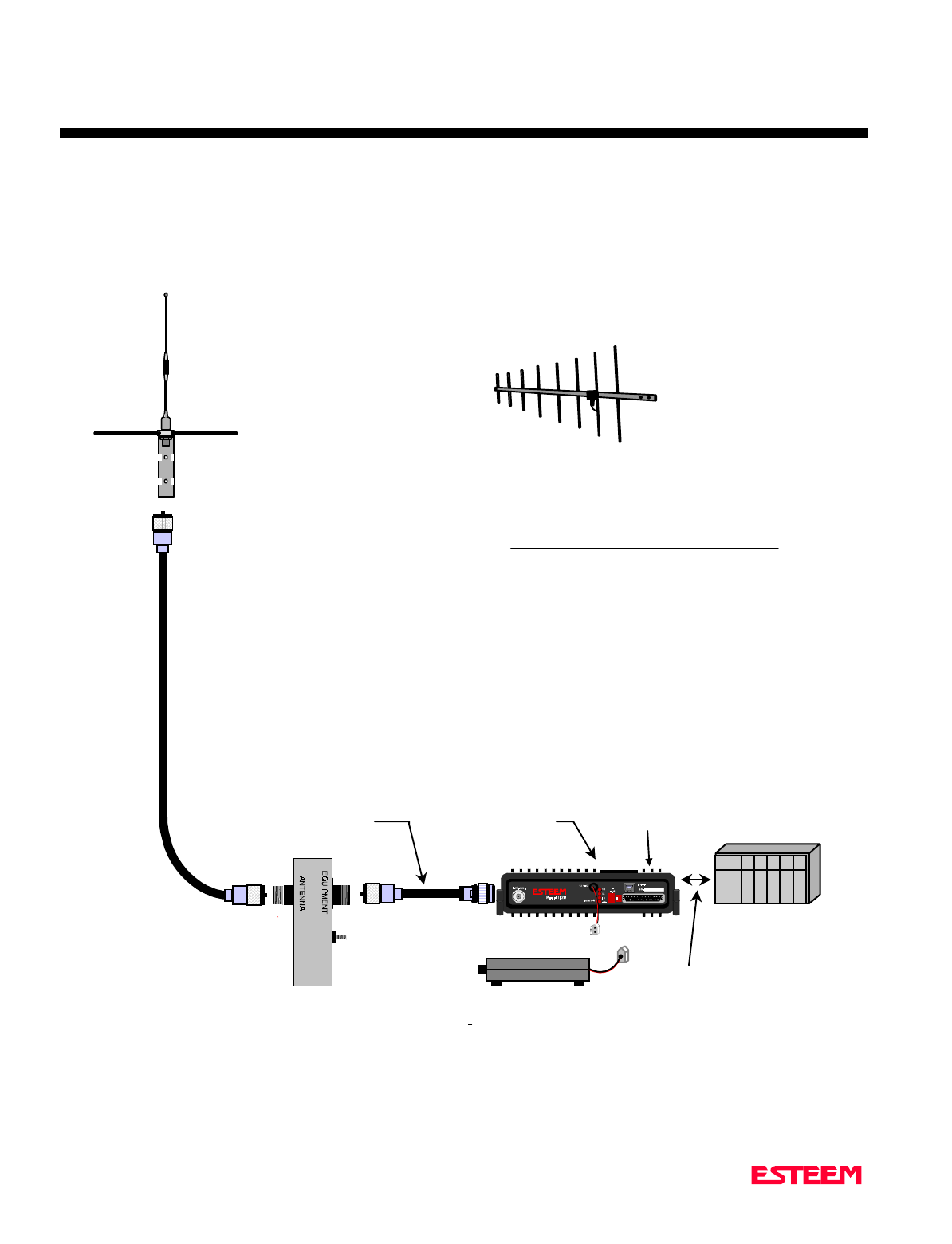
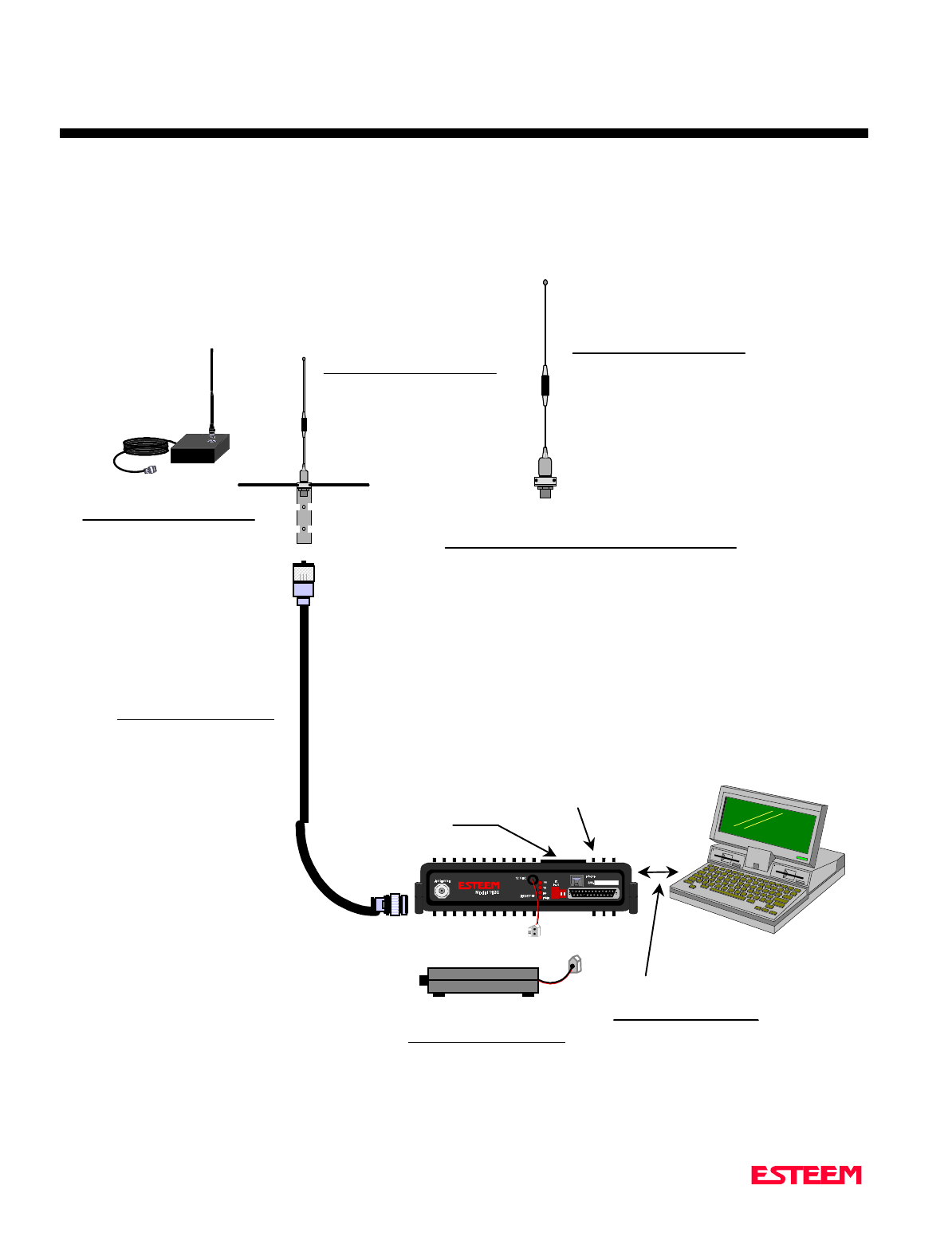
Models 192C and 192F Typical Outdoor
Antenna Installation Diagram
N Male
Connector
N Male
Connector
TNC Male
Connector
2 Pin Molex
Connector
User’s
Device
RG-8 Coax
(EST Part No. AA234
RS-232C
Setup
Switches
RS-232C, 422, & 485
Interface Connector
NOTES
1. Use coax cable runs as short as practical to
minimize cable losses.
2. Vapor wrap all external antenna coax
connections with vinyl wrap (EST Part No. AA241)
and apply Scotchkote Electrical Coating (EST Part
No. AA242).
3. Contact EST for recommendations regarding
antenna mounting hardware and installation tips.
4. Ground antenna structure, base and lightning
arrestor.
ANTENNA
RECOMMENDATIONS
1. Omni-Directional
(EST P/N AA20M or
ASP682).
2. Directional (EST P/N
AA202M).
Directional
Antenna
Omni-Directional
Antenna
UHF Male
Connector
for AA235
or AA238
ANTENNA FEEDLINE
RECOMMENDATIONS
1. Up to 50 ft. use RG-8
Coax (EST P/N AA235)
or AA237.
2. Over 50 ft. use 1/2”
heliax (EST P/N AA236)
or AA238.
N Male
Connector
for AA236
or AA237
12 VDC Power Supply
(EST Part No. AA174)
RS-232C,422, or 485
Interface Cable
(EST Part No. AA06,
AA061, AA07, or
custom depending on
device)
Lightning Arrestor
(EST Part No. AA162)
CHAPTER 6
ANTENNAS
Revised: 27 Mar 01 6-6
Model 192M Typical Indoor & Mobile
Equipment Diagram
Omni-Directional Antenna
Magnetic Mount. EST P/N
AA19M with 19 inch
rubber duck radial with
approximately 12 ft. of
integral RG-58 cable for
direct connection to
ESTeem.
UHF Male
Connector
ANTENNA FEEDLINE
RECOMMENDATIONS
1. Up to 50 ft. use RG-8
Coax (EST P/N AA233).
2. Over 50 ft. call EST.
TNC Male
Connector
12 VDC POWER SUPPLY
RECOMMENDATIONS
EST P/N AA174
Battery Packs
2 Pin Molex
Connector
User’s
Device
RS-232C
Setup
Switches
RS-232C, 422, & 485
Interface Connector
Omni-Directional Antenna
Permanent Mount. EST
P/N AA20M with 21 inch
vertical radials.
RS-232C,422, or 485
INTERFACE CABLE
EST P/N AA06,
AA061, AA07, or
custom depending on
device.
ANTENNA
RECOMMENDATIONS
NOTES
1. Use coax cable runs as short as practical to
minimize cable losses.
2. Vapor wrap all external antenna coax
connections with vinyl wrap (EST Part No. AA241)
and apply Scotchkote Electrical Coating (EST Part
No. AA242).
3. Contact EST for recommendations regarding
antenna mounting hardware and installation tips.
4. Ground antenna structure, base and lightning
arrestor.
Omni-Directional Antenna
Vehicle Mount. EST P/N
AA191 with integral 17 ft.
of RG-58 cable for direct
connection to ESTeem.
CHAPTER 6
ANTENNAS
Revised: 27 Mar 01 6-7
Model 192C and 192F Typical Indoor & Mobile
Antenna Installation Diagram
UHF Male
Connector
ANTENNA FEEDLINE
RECOMMENDATIONS
1. Up to 50 ft. use RG-8
Coax (EST P/N AA233).
2. Over 50 ft. call EST.
TNC Male
Connector
12 VDC POWER SUPPLY
RECOMMENDATIONS
EST P/N AA174
Battery Packs
2 Pin Molex
Connector
RS-232C
Setup
Switches
RS-232C, 422, & 485
Interface Connector
RS-232C,422, or 485
INTERFACE CABLE
EST P/N AA06,
AA061, AA07, or
custom depending on
device.
Omni-Directional Antenna
Magnetic Mount. EST P/N
AA19C/F with 19 inch
rubber duck radial with
approximately 12 ft. of
integral RG-58 cable for
direct connection to
ESTeem.
Omni-Directional Antenna
Permanent Mount. EST
P/N AA20C/F with 29 inch
vertical radials.
ANTENNA
RECOMMENDATIONS Omni-Directional Antenna
Vehicle Mount. EST P/N
AA191C/F with integral 17
ft. of RG-58 cable for
direct connection to
ESTeem.
NOTES
1. Use coax cable runs as short as practical to
minimize cable losses.
2. Vapor wrap all external antenna coax
connections with vinyl wrap (EST Part No. AA241)
and apply Scotchkote Electrical Coating (EST Part
No. AA242).
3. Contact EST for recommendations regarding
antenna mounting hardware and installation tips.
4. Ground antenna structure, base and lightning
arrestor.
CHAPTER 6
ANTENNAS
Revised: 27 Mar 01 6-8
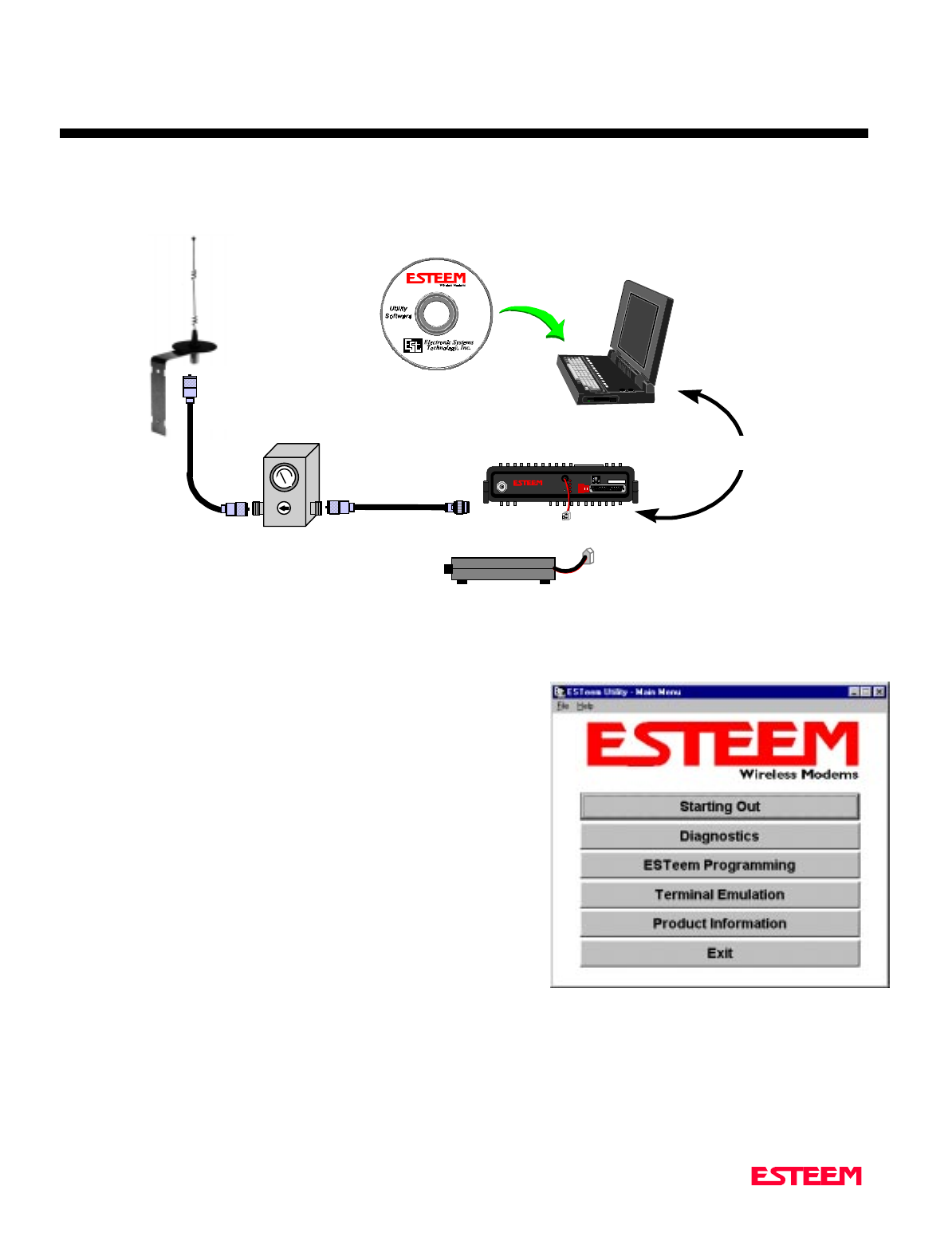
ESTeem SWR Measurement Block Diagram
Programming The ESTeem Model 192 For SWR Measurements
1. Configure the hardware as per the above diagram.
2. Turn Switch 2 on the RS-232 Setup Switch (located on the rear of
the ESTeem) to the OFF position.
3. Reset the ESTeem (front panel push button).
4. Install the ESTeem Utility on the PC hard drive as per instructions
with the software.
5. From Utility Main Menu (Figure 1) select the Terminal Emulation
Mode.
6. In the Terminal Emulation Mode type the following commands
followed by a RETURN.
FA Return This returns the unit to factory default
parameters.
RAD ON Return Enable the RADIO ON command. The
transmitter will alternate ON for 10 seconds
and OFF for 3 seconds.
7. When the testing is completed, type the following:
RAD OFF Return This disables the RADIO ON command.
N Male
Connector N Male
Connector
TNC Male
Connector
Antenna
2 Pin Molex
Connector
RS-232C Interface Cable
(EST P/N AA061)
UHF Male
Connector
SWR Meter
RG-8 Cable
(EST P/N AA230)
12 VDC Power Suppl
y
(EST P/N AA174)
S/N:T/E
TX
RX
PWR
IR
Port
Phone
Model 192S
Antenna 12 VD C
RESE T
ESTeem Model 192 Utility
Software Windows Version
Figure 1: ESTeem Utility Main Menu


CHAPTER 7
THEORY OF OPERATION
Revised: 27 March 01 7-2
INTRODUCTION
ESTeem wireless modem products provide a "Wireless
Solution" by eliminating conventional hardwiring of
leased phone lines.
All of the ESTeem models come with the industry
standard RS-232C, RS-422, and RS-485 asynchronous
communications ports to give the user a new dimension
to "Local Area Networking".
Our packet burst, frequency agile communications
products allow the user to create a "Radio Area Network"
of up to 255 users on a single frequency. The packet
burst communications technique was chosen to give the
system very high data integrity in high noise industrial
environments. The ESTeem incorporates a method of
error checking that provides received data accuracy of
greater than one part in 100 million.
Internal Digi-Repeater features allow the user to increase
operating range by relaying transmission through a
maximum of three ESTeems to reach the destination
ESTeem. An ESTeem can operate as an operating node,
a repeater node, or both simultaneously for added
flexibility.
"Private Data Communications" is provided by the use of
an interleaving technique of the modulated data, user
definable commands for unit addressing, network
addressing, and security lock-out of software
programming. If higher security is required, the ESTeem
is compatible with asynchronous Data Encryption
Standard (DES) encryption devices.
The ESTeem has programmable software commands to
allow the user to easily configure the unit for any
application or mission. The ESTeem setup parameters
are saved in non-volatile memory.
When you buy ESTeem products you are getting
equipment designed by the company that holds the
United States and Canadian patent for the wireless
modem. We are proud to say that we design, develop and
manufacture our products in the United States. Each
ESTeem is subjected to a rigorous quality control bench
test before shipping to insure our customers have
out-of-the-package reliability. We also have a dedicated
Customer Support Staff, Field Engineering Services and
Factory Training classes to make sure that your
application problems are solved.
HOW IT WORKS
Now, as you can probably guess, the ESTeem is a
sophisticated piece of technology, however the concept is
easy to comprehend if you understand packet radio.
All packet systems, whether hardwired or radio, share the
same principle of operation; data is taken from your
standard RS-232C, RS-422, or RS-485 asynchronous port
and is transmitted in "Blocks". Think of this block as an
"Electronic Envelope" that we call a packet. The size of
the packet can be defined by the user from 1 to 2000
bytes of information. Reducing the size of the packet
allows the ESTeem to operate better in high EMF noise
environments, because by reducing the packet size you
reduce transmission exposure time on the radio waves
thereby increasing your probability of a successful
transmission.
Once this packet of data is formed, it’s transmitted in a
"burst," one ESTeem to another, hence the term "packet
burst communications". Now, if more than one packet is
required to send the data then the ESTeem goes into full
automatic mode and transmits additional packets.
Before an ESTeem transmits its packet it listens to ensure
that the air waves are clear before transmitting. This
listen before transmit scheme is called "carrier sensed
multiple access," or CSMA.
When a "packet" has been transmitted, every modem in
radio range on the same frequency hears it. To design a
modem to communicate with a network of modems it has
to be "address specific" so only the modem you want to
talk to accepts your information. It's like yelling into a
crowd of 255 people but you want only the person’s name
you called to acknowledge (ACK). Well, very simply,
that's how the ESTeem works. Once the address you're
calling receives your packet, it's checked for accuracy.
Accuracy is probably the single most important part of
any communication device. The ESTeem uses Forward
Error Correction (FEC) and a 32 bit Cyclic Redundancy
Check (CRC) which is a very sophisticated method of
checking the data integrity of the packet once its been
received. The CRC insures data integrity greater than
one part in one hundred million. Once the CRC is
completed on the received packet, the data is outputted to
the user and a positive acknowledgment (ACK) is
transmitted back to the sender.

CHAPTER 7
THEORY OF OPERATION
Revised: 27 March 01 7-3
It's safe to assume that the data you receive is good data
or you get nothing at all using the CRC technique. If no
ACK is returned after a given delay, the sender assumes
the packet was not received and "retries" the
transmission. The number of retries are user definable
from 1 to 255, allowing the unit to automatically retry
sending the packet.
SPECTRUM UTILIZATION
The ESTeem uses a "listen before transmit" or Carrier
Sensed Multiple Access (CSMA) scheme. This means
only one unit in a network is allowed to transmit at a
time. By fixing each user's communication window and
allowing the computer in the ESTeem to be the Air
Traffic Controller, many individual users can share one
frequency. The ESTeem firmware can support up to 255
ESTeems on a single channel or frequency. For example
in the United States there are 1600 frequencies (12.5 kHz
channel spacing) in UHF, giving a network density of
greater than 408,000 users in a given cell or geographical
area. Once you are out of radio range, you can construct
another cell of users.
The CSMA technique is a very efficient way to manage
your network of ESTeems and prevent communication
bottlenecks. In addition, an anti-collision software
scheme is used to recover data if two or more units
transmit at exactly the same time. When this feature is
added the technical term for this technique is now called
CSMA-CD (collision detection).
By using this communications technique only one
frequency channel is needed with a very narrow
bandwidth (this is called narrow band FM modulation)
thereby saving valuable radio spectrum space.
PACKET PROTOCOLS
By using CSMA no polling station or token is required in
the ESTeem network. When an ESTeem has information
to send it will check to see if the channel is clear before
transmitting its packet and await an (ACK). The
ESTeem is a Master/Master system, meaning any
ESTeem can communicate with any other ESTeem.
FLOW CONTROL
The ESTeem supports hardware and software flow
control, which allow different devices on the network to
communicate at different baud rates. In addition to flow
control the ESTeem also has a 4000 byte data buffer on
both the receive and transmit buffers in the unit.
DATA PRIVACY
Data privacy in the ESTeem is provided by three levels of
data encoding in the firmware and by the user being able
to define over four security and communications
parameters (Unit Address, Network ID, and Operating
Frequency) that allow communications access to the
modem giving over 100 million combinations. If higher
security is required, the units are compatible with
asynchronous Data Encryption Standard (DES)
encryption peripherals.
EFFECTIVE BAUD RATE
The maximum input baud rate to the modem is 19,200
baud, asynchronous, full duplex, but this is misleading
since the ESTeems actually communicate to each simplex
over the RF link, at 19,200 bps (25 kHz channel spacing
- Model 192C/F) or 9,600 bps (12.5 kHz channel spacing
- Model 192C/F). The effective baud rate is a function of
the above plus the packet length variable in the ESTeem
(definable from 1 to 2000 bytes). If the packlength
variable is set to 2000 bytes the effective baud rate is
approximately 18,000 baud (25 kHz channel spacing) or
9,000 baud (12.5 kHz channel spacing) the effective baud
rate will degrade as the packlength variable is reduced.
Another item that must be understood is transmission
turn around time. Remember that the ESTeem sends a
data packet and waits for an (ACK) from the destination
modem before another packet is transmitted. All radio
transmitters have a fixed delay time, this is the amount of
time it takes the transmitter to stabilize once it is
energized before it can send data. In the ESTeem the
delay is approximately 15 milliseconds one way which
includes transmitter turn-on time and packet frame
overhead or a total turn around time accounting for the
(ACK) of 30 milliseconds. Therefore total time to send a
data packet is 30 milliseconds plus the time required to
send the data (i.e. number of bits sent/19,200 b/s).

APPENDICES
APPENDIX “A” FCC INFORMATION (USA Only)
APPENDIX “B” SPECIFICATIONS
ESTeem Specifications
Antenna Specifications
APPENDIX “C” TABLES/DIAGRAMS
ESTeem Command Error Message Table
ESTeem System Status Message Table
ESTeem System Error Message Table
APPENDIX “D” ESTEEM SOFTWARE COMMANDS
Factory Default Settings
Definitions

APPENDIX A
FCC LICENSING
Revised: 27 Mar 01 APX A-2
INFORMATION TO USERS
WARNING: This equipment has been tested and found to
comply with the limits for a Class A digital
device, pursuant to Part 15 of the FCC Rules.
These limits are designed to provide
reasonable protection against harmful
interference when the equipment is operated
in a commercial environment. This
equipment generated, uses, and can radiate
radio frequency energy and, if not installed
and used in accordance with the instruction
manual, may cause harmful interference to
radio communications. Operation of this
equipment in a residential area is likely to
cause harmful interference in which case the
user will be required to correct the
interference at his own expense.
To insure compliance to FCC non-
interference regulations, peripherals attached
to this modem require shielded I/O cables.
If this equipment does cause interference to
radio or television, which can be determined
by turning the equipment off and on, the user
is encouraged to try to correct the interference
by one or more of the following measures:
1. Re-orient the radio/TV receiving antenna.
2. Re-orient the modem antenna.
3. Relocate the modem with respect to the radio/TV
receiving antenna.
4. Plug the power supply for the modem into a different
outlet so that the modem and radio/TV receiver are on
different branch circuits.
5. Verify that the modem chassis is connected to an earth
ground.
6. Attach a split bead (FAIR-RITE PN 2643164251) to
the RS-232 cable.
If necessary, the user should consult the dealer or an
experienced radio/TV technician for additional suggestions.
The user may find the following booklet prepared by the
FCC helpful.
"How to Identify and Resolve Radio-TV Interference
Problems"
This booklet is available from the U.S. Government Printing
Office, Washington, D.C. 20402 - Stock No. 004-000-
00245-4. Application forms for the license are available
from the nearest office of the FCC.
Electronic Systems Technology maintains a list of
consultants that provide professional services at a
reasonable cost to assists the users in licensing.
Other Information
Model 192C
25 KHz Channel Spacing, 19,200 bps
FCC Type Acceptance No: ENPESTEEM192
Emissions Designator: 17K6F1D
12.5 KHz Channel Spacing, 9,600 bps
FCC Type Acceptance No: ENPESTEEM192A
Emissions Designator: 10K8F1D
12.5 KHz Channel Spacing, 19,200 bps
Industry Canada Type Acceptance No: 2163 195 214A
Emissions Designator: 10K0F1D
Model 192F
25 KHz Channel Spacing, 19,200 bps
Industry Canada Type Acceptance No: 2163 195 214A
Emissions Designator: 17K6F1D
12.5 KHz Channel Spacing, 9,600 bps
Industry Canada Type Acceptance No: 2163 195 214A
Emissions Designator: 10K8F1D
25 KHz Channel Spacing, 19,200 bps
Malaysia Telecom No: RADL 60A 1097 S
Emissions Designator: 17K6F1D
Model 192M
25 kHz Channel Spacing, 19,200 bps
U.S.A. Type Acceptance: ENPESTEEM192M
Emission Designator: 17K6F1D
12.5 kHz Channel Spacing, 9,600 bps
U.S.A. Type Acceptance: ENPESTEEM192M
Emission Designator: 10K8F1D
25 kHz Channel Spacing, 19,200 bps
Canada: 2163195385A
Emission Designator: 17K6F1D
12.5 kHz Channel Spacing, 9,600 bps
Canada: 2163195385A
Emission Designator: 10K8F1D

APPENDIX A
FCC LICENSING
Revised: 27 Mar 01 APX A-3
FEDERAL COMMUNICATIONS COMMISSION FIELD OFFICES
ALASKA
1011 E. Tudor Rd.
Rm 240 Box 2955
Anchorage, AK 99510
CALIFORNIA
7840 El Cajon Blvd
Suite 405
La Mesa, CA 92041
3711 Long Beach Blvd
Suite 501
Long Beach, CA 90807
323A Battery St
San Francisco, CA 94111
COLORADO
Executive Tower
1405 Curtis St
Suite 2925
Denver, CO 80202
FLORIDA
919 Federal Bldg
51 SE First Ave.
Miami, FL 33130
1211 N. Westshore
Suite 601
A.D. P. Building
Tampa, FL 33607
GEORGIA
Massell Bldg. 440
1365 Peachtree NE
Atlanta, GA 30309
HAWAII
7304 Prince Kuhi
Federal Building
Honolulu, HI
HAWAII
300 Almoana Blvd.
P.O. Box 50023
Honolulu, HI
ILLINOIS
3935 Federal Bldg
230 S. Dearborn
Chicago, IL 60604
LOUISIANA
1009 Edw Hebert Bldg.
600 South Street
New Orleans, LA 70130
MARYLAND
1017 Geo. Fallon
Building 31
Hopkins Plaza
Baltimore, MD
MASSACHUSETTS
1600 Customhouse
165 State Street
Boston, MA 02109
MICHIGAN
1054 Federal Building
231 W LaFayette
Detroit, MI 48225
MINNESOTA
691 Federal Building
316 N Robert St.
St. Paul, MN
MISSOURI
Brywood Office Tower
6800 E. 63rd Street
Kansas City, MO
NEW YORK
1307 Federal Building
111 W. Huron
Buffalo, NY 14202
201 Varick Street
New York, NY 10014
OREGON
1782 Federal Building
1220 SW 3rd Avenue
Portland, OR 97204
PENNSYLVANIA
Room 404
2300 E. Lincoln H
Langhorne, PA
PUERTO RICO
747 Federal Building
Carlo Chardon Ave.
Hato Rey, PR 00918
TEXAS
Cabeli Building
1100 Commerce
Dallas, TX 75242
5636 Federal Building
515 Rusk Avenue
Houston, TX 77002
VIRGINIA
Military Circle
870 N. Military Hwy.
Norfolk, VA 23502
WASHINGTON
3256 Federal Building
915 Second Avenue
Seattle, WA 98174

APPENDIX A
FCC LICENSING
Revised: 6 Jul 98 APX A-4
FEDERAL COMMUNICATIONS COMMISSION FIELD OFFICES
ALASKA
1011 E. Tudor Rd.
Rm 240 Box 2955
Anchorage, AK 99510
CALIFORNIA
7840 El Cajon Blvd
Suite 405
La Mesa, CA 92041
3711 Long Beach Blvd
Suite 501
Long Beach, CA 90807
323A Battery St
San Francisco, CA 94111
COLORADO
Executive Tower
1405 Curtis St
Suite 2925
Denver, CO 80202
FLORIDA
919 Federal Bldg
51 SE First Ave.
Miami, FL 33130
1211 N. Westshore
Suite 601
A.D. P. Building
Tampa, FL 33607
GEORGIA
Massell Bldg. 440
1365 Peachtree NE
Atlanta, GA 30309
HAWAII
7304 Prince Kuhi
Federal Building
Honolulu, HI
HAWAII
300 Almoana Blvd.
P.O. Box 50023
Honolulu, HI
ILLINOIS
3935 Federal Bldg
230 S. Dearborn
Chicago, IL 60604
LOUISIANA
1009 Edw Hebert Bldg.
600 South Street
New Orleans, LA 70130
MARYLAND
1017 Geo. Fallon
Building 31
Hopkins Plaza
Baltimore, MD
MASSACHUSETTS
1600 Customhouse
165 State Street
Boston, MA 02109
MICHIGAN
1054 Federal Building
231 W LaFayette
Detroit, MI 48225
MINNESOTA
691 Federal Building
316 N Robert St.
St. Paul, MN
MISSOURI
Brywood Office Tower
6800 E. 63rd Street
Kansas City, MO
NEW YORK
1307 Federal Building
111 W. Huron
Buffalo, NY 14202
201 Varick Street
New York, NY 10014
OREGON
1782 Federal Building
1220 SW 3rd Avenue
Portland, OR 97204
PENNSYLVANIA
Room 404
2300 E. Lincoln H
Langhorne, PA
PUERTO RICO
747 Federal Building
Carlo Chardon Ave.
Hato Rey, PR 00918
TEXAS
Cabeli Building
1100 Commerce
Dallas, TX 75242
5636 Federal Building
515 Rusk Avenue
Houston, TX 77002
VIRGINIA
Military Circle
870 N. Military Hwy.
Norfolk, VA 23502
WASHINGTON
3256 Federal Building
915 Second Avenue
Seattle, WA 98174

APPENDIX B
SPECIFICATIONS
ESTeem General Specifications
Revised: 27 Mar 01 APX B-1
SWITCHES:
• CPU Reset
• RS-232C/422/485 Setup
LED INDICATORS:
• Power On
• Receiver Carrier Detect
• Transmitter Enable
• Link Connect/Disconnect
• Auto Connect Enabled
• RS-232C/422/485 Framing
Error
I/O - CONNECTORS:
• Asynchronous Full Duplex,
RS-232C, RS-422 and RS 485
with 25 Pin Sub D Connector.
• Antenna Output - TNC
connector
• Input Power - 2 pin molex
ADDRESSING RANGE:
• 1 to 255
DATA INPUTS:
• Selectable 600 to 19,200 baud
• 7 to 8 data bits
• Even, odd, or no parity
• One or two stop bits
DATA BUFFERS:
• Transmit 4000 bytes
• Receive 4000 bytes
FLOW CONTROL:
• Hardware or Software
DATA TRANSMISSION
PROTOCOL:
• Carrier Sensed Multiple
Access with Collision
Detection (CSMA-CD)
ERROR CHECKING:
Forward error correction and 32
Bit Cyclic Redundancy Check
(CRC) with packet acknowledge
and retry
MINIMUM RADIO TURN
AROUND TIME:
• < 15 ms + Data (W/O ACK)
• < 30 ms + Data (W/ACK)
POWER
REQUIREMENTS:
Models 192C & 192F
• 11 to 15 VDC @ 400 ma Rx
2 W RF 1.5 A Tx
4 W RF 2.0 A Tx
Model 192M
• 11 to 15 VDC @ 400 ma Rx
2 W RF 1.5 A Tx
4 W RF 2.0 A Tx
SIZE:
• 2.45 in. Height
• 9.37 in. Width
• 8.16 in. Length
WEIGHT:
• 5 lbs.
ENVIRONMENT:
• -30 TO 50 ° C.
• 95% non-condensing
WARRANTY:
• 1 Year

APPENDIX B
SPECIFICATIONS
ESTeem Transceiver Specifications
Revised: 27 Mar 01 APX B-2
ESTeem Model 192C ESTeem Model 192F
Frequency Range 450 to 470 MHz 400 to 420 MHz
Frequency Selection Digitally Synthesized - Software Selectable Digitally Synthesized - Software Selectable
Frequency Stability +/- 1 ppm +/- 1 ppm
Frequency Selectability 6.25KHz 6.25KHz
RF Data Rate 19,200 bps @ 25 KHz Channel Spacing
U.S.A. Type Acceptance:
ENPESTEEM192
Emission Designator: 17K6F1D
9,600 bps @ 12.5 KHz Channel Spacing
U.S.A. Type Acceptance:
ENPESTEEM192A
Emission Designator: 10K8F1D
19,200 bps @ 12.5 KHz Channel Spacing
Canada: 2163 195 214A
Emission Designator: 10K0F2D
19,200 bps @ 25 KHz Channel Spacing
Canada: 2163 195 214A
Emission Designator: 17K6F1D
9,600 bps @ 12.5 KHz Channel Spacing
Canada: 2163 195 214A
Emission Designator: 10K8F2D
Transmitter Modulation DC to 4800 Hz @ 19,200 bps DC to 4800 Hz @ 19,200 bps
DC to 2400 Hz @ 9,600 bps DC to 2400 Hz @ 9,600 bps
Transmitter Deviation 4 KHz @ 19,200 bps 4 KHz @ 19,200 bps
3 KHz @ 9,600 bps 3 KHz @ 9,600 bps
Transmitter RF Power Output 2 Watts
(4 Watts optional) 4 Watts
(2 Watts optional)
Transmitter Duty Cycle 100% 100%
Transmitter Spurious & Harmonics > 55 dB down from carrier > 55 dB down from carrier
Transmitter Rise Time 1 msec 1 msec
Transmitter FM Hum & Noise > 50 dB down from carrier > 50 dB down from carrier
Receiver Sensitivity: -101 dBm -101 dBm
Receiver Spurious & Image Rejection > 50 dB > 50 dB
Receiver Squelch Sensitivity Adjustable - Four Levels Adjustable - Four Levels
Receiver Adjacent Channel Rejection > 70 dB > 70 dB
Receiver Modulation Acceptance: 25 KHz 25 KHz
Receiver Base Bandwidth: 4.8 KHz 4.8 KHz
Transmit/Receive Switch Integral to Unit Integral to Unit
RF Output Impedance 50 Ohms 50 Ohms
RF Input/Output Connector TNC Female TNC Female
Power Supply Voltage 12 to 15 VDC 12 to 15 VDC
Power Supply Current @ 12 VDC 400 ma Receive
1.5 A Transmit (2 W RF Output)
2.0 A Transmit (4 W RF Output)
400 ma Receive
1.5 A Transmit (2 W RF Output)
2.0 A Transmit (4 W RF Output)
Input Power Connector 2 Pin Molex (male) 2 Pin Molex (male)
Temperature Range -30 to + 50 ° C. -30 to + 50 ° C.
Size 2.45 in. H x 9.37 in. W x 8.16 in. L. 2.45 in. H x 9.37 in. W x 8.16 in. L.
Weight 5 lbs. 5 lbs.

APPENDIX B
SPECIFICATIONS
ESTeem Transceiver Specifications
Revised: 27 Mar 01 APX B-3
ESTeem Model 192M
Frequency Range 150 to 174 MHz
Frequency Selection Digitally Synthesized - Software Selectable
Frequency Stability +/- 2.5 ppm
Frequency Selectability 12.5 kHz
RF Data Rate 19,200 bps @ 25 kHz Channel Spacing
U.S.A. Type Acceptance:
ENPESTEEM192M
Emission Designator: 17K6F2D
9,600 bps @ 12.5 kHz Channel Spacing
U.S.A. Type Acceptance:
ENPESTEEM192M
Emission Designator: 10K8F2D
19,200 bps @ 25 kHz Channel Spacing
Canada: 2163195385A
Emission Designator: 17K6F2D
9,600 bps @ 12.5 kHz Channel Spacing
Canada: 2163195385A
Emission Designator: 10K8F2D
Transmitter Modulation DC to 4800 Hz @ 19,200 bps
DC to 2400 Hz @ 9,600 bps
Transmitter Deviation 4 kHz @ 19,200 bps
3 kHz @ 9,600 bps
Transmitter RF Power Output 2 Watts
(4 Watts optional)
Transmitter Duty Cycle 100%
Transmitter Spurious & Harmonics > 55 dB down from carrier
Transmitter Rise Time 1 msec
Transmitter FM Hum & Noise > 50 dB down from carrier
Receiver Sensitivity: -101 dBm
Receiver Spurious & Image Rejection > 50 dB
Receiver Squelch Sensitivity Adjustable - Four Levels
Receiver Adjacent Channel Rejection > 70 dB
Receiver Modulation Acceptance: 25 kHz
Receiver Base Bandwidth: 4.8 kHz
Transmit/Receive Switch Integral to Unit
RF Output Impedance 50 Ohms
RF Input/Output Connector TNC Female
Power Supply Voltage 12 to 15 VDC
Power Supply Current @ 12 VDC 400 ma Receive
1.5 A Transmit (2 W RF Output)
2.0 A Transmit (4 W RF Output)
Input Power Connector 2 Pin Molex (male)
Temperature Range -30 to + 50 ° C.
Size 2.45 in. H x 9.37 in. W x 8.16 in. L.
Weight 5 lbs.
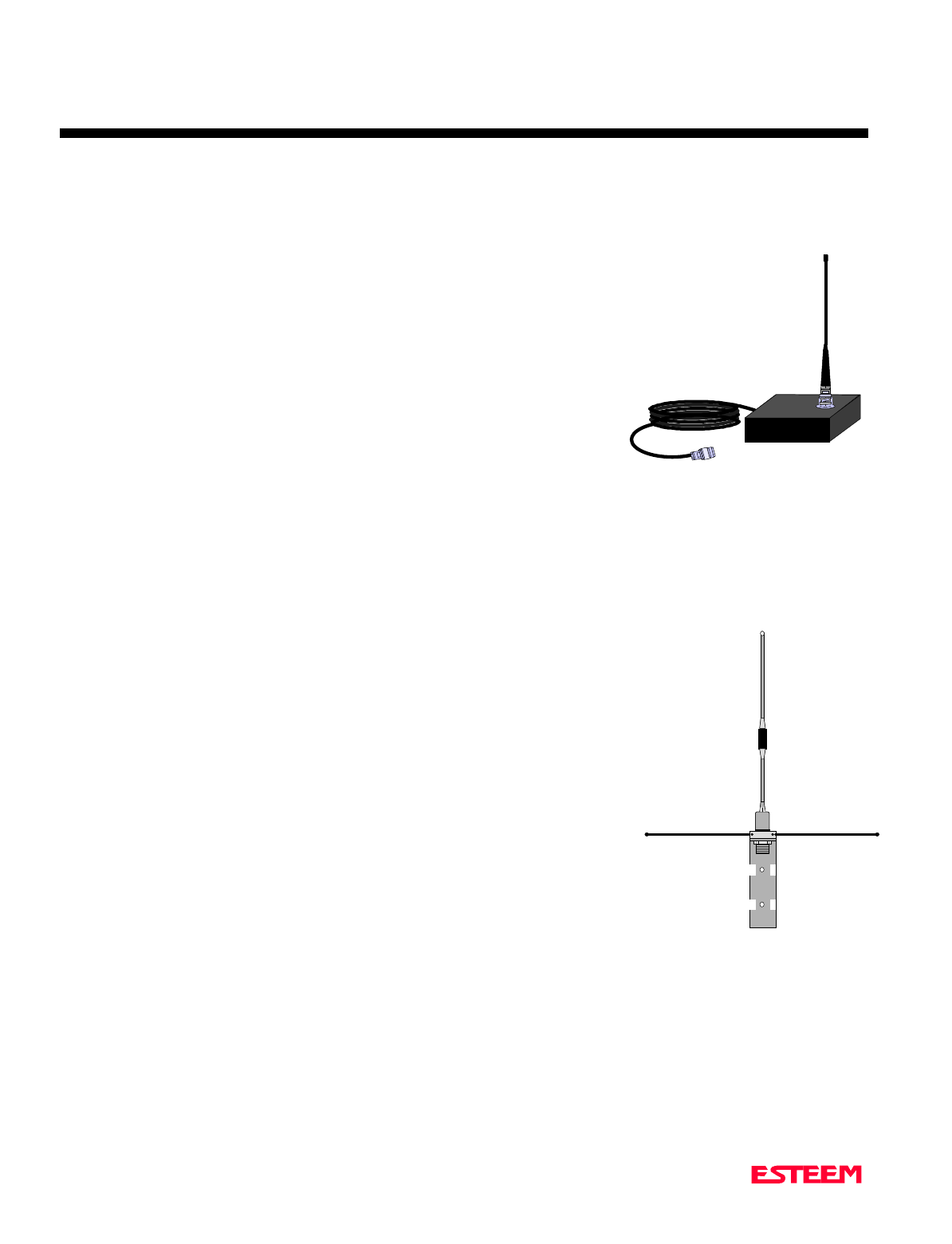
APPENDIX B
SPECIFICATIONS
Model 192C & F Antennas
Revised: 27 Mar 01 APX B-4
Model No: AA19C & AA19F
Antenna Type: Omni-Directional, ½ Wave
Applications:Mobile Mount.
Frequency: 450 to 470 MHz - AA19C
400 to 420 MHz - AA19F
Polarization: Vertical
Impedance: 50 ohms
Gain: 2 db.
VSWR: < 2 to 1
Front To Back Ratio: n/a
Horizontal Beamwidth: n/a
Vertical Beamwidth: 60 degrees
Antenna Material: Rubber duck whip.
Mounting Hardware: Magnetic base.
Antenna Connector:TNC with 12 feet integral RG-58 cable.
Antenna Envelope: 16 in. length. Magnetic base 3.5 in. by 3 in by 1 in.
Weight: 1 lb. 5 oz.
Model No: AA20C & AA20F
Antenna Type: Omni-Directional, DC grounded, Collinear 5/8 wave
over 1/2 wave.
Applications:Fixed base or mobile mounting. L shaped mounting
bracket may be removed for panel mounting. Ground
plane radials may be removed depending on
application.
Frequency: 450 to 470 MHz - AA20C
400 to 420 MHz - AA20F
Polarization: Vertical
Impedance: 50 ohms
Gain: 4.5 dB.
VSWR: < 1.5
Front To Back Ratio: n/a
Horizontal Beamwidth: n/a
Vertical Beamwidth: 30 degrees
Antenna Material: Stainless steel whip and ground plane radials. All
other hardware anodized metal.
Mounting Hardware: Stainless steel clamps for mounting to ¾ in. to 1 /2 in. pipe with right angle mount or direct
mount.
Antenna Connector:UHF Female (S-239)
Antenna Envelope: 37 ½ in. length by 16 in width with ground plane radials.
Weight: 2 lbs.
Model AA19
Model AA20
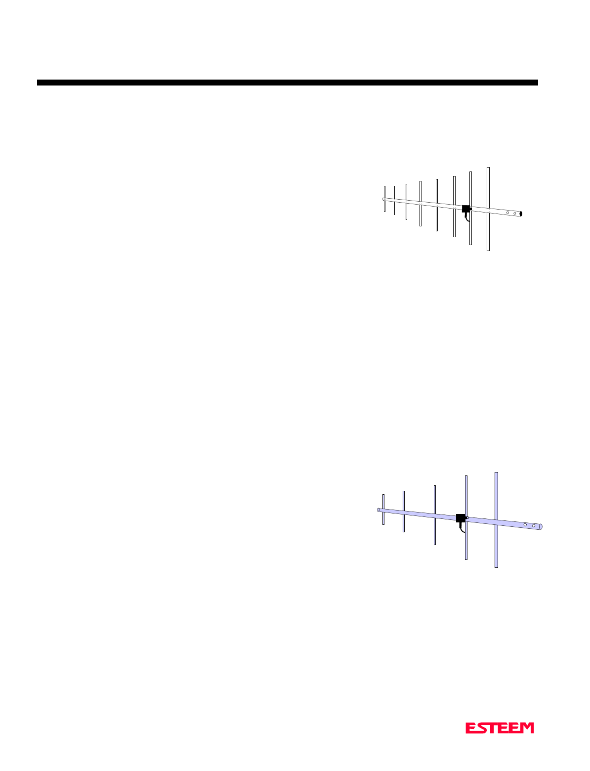
APPENDIX B
SPECIFICATIONS
Model 192C & F Antennas
Revised: 27 Mar 01 APX B-5
Model No: AA201C & AA201F
Antenna Type: Directional, DC grounded, 8 element yagi.
Applications:Fixed base.
Frequency: 450 to 470 MHz - AA201C
400 to 420 MHz - AA201F
Polarization: Vertical
Impedance: 50 ohms
Gain: 11 dB
VSWR: < 1.5
Front To Back Ratio: 23 dB
Horizontal Beamwidth: 42 degrees
Vertical Beamwidth: 50 degrees
Antenna Material: High strength aluminum painted black.
Mounting Hardware: Heavy duty U bolts for mounting to ¾ in. to 1 ½ in. pipe with right angle mount or direct
panel mount.
Antenna Connector:UHF Female (SO-239)
Maximum Power Input: 300 Watts
Antenna Envelope: 60 in. length by 15 in. width
Windload (RWV): 100 mph
Wind Load,
Flat Plate (Ft2): .52
Lateral Thrust @RWV: 14 mph
Bending Moment @RWV: 23 ft. lbs.
Weight: 2 lbs.
Model No: AA202C & AA202F
Antenna Type: Directional, DC grounded, 5 element yagi.
Applications:Fixed base.
Frequency: 450 to 470 MHz - AA202C
400 to 420 MHz - AA202F
Polarization: Vertical or Horizontal
Impedance: 50 ohms
Gain: 10 dB
VSWR: < 1.5
Front To Back Ratio: 20 dB
Horizontal Beamwidth: 59 degrees
Vertical Beamwidth: 53 degrees
Antenna Material: High strength aluminum with gold chromate finish.
Mounting Hardware: Heavy duty U bolts for mounting up to 2 1/8 in. pipe with right angle mount or direct panel
mount.
Antenna Connector:UHF Female (SO-239)
Maximum Power Input: 300 Watts
Antenna Envelope: 34.5 in. length by 13.25 in. width
Windload (RWV): 100 mph
Weight: 1.68 lbs.
Model 201
Model 202
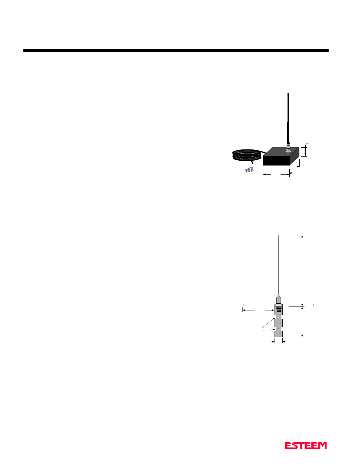
APPENDIX B
SPECIFICATIONS
Model 192M Antennas
Revised: 27 Mar 01 APX B-6
Model No: AA19M
Antenna Type: Omni-Directional, ½Wave over ¼ Wave.
Applications: Mobile Mount.
Frequency: 150 to 174 MHz
Polarization: Vertical
Impedance: 50 ohms
Gain: Unity
VSWR: < 1.5 to 1
Front To Back Ratio: n/a
Horizontal Beamwidth:n/a
Vertical Beamwidth: 60 degrees
Antenna Material: Rubber duck whip.
Mounting Hardware: Magnetic base.
Antenna Connector: TNC with 12 feet integral RG-58 cable.
Antenna Envelope: 11 in. length. Magnetic base 3.5 in. by 3 in. by 1 in.
Weight: 1 lb. 5 oz.
Model No: AA20M
Antenna Type: Omni-Directional, DC Grounded, 5/8 Wave.
Applications: Fixed base or mobile mounting. L shaped
mounting bracket may be removed for panel
mounting. Ground plane radials may be removed
depending on application.
Frequency: 150 to 175 MHz
Polarization: Vertical
Impedance: 50 ohms
Gain: 3.0 dB with ground plane radials
VSWR: < 1.5
Front To Back Ratio: n/a
Horizontal Beamwidth:n/a
Vertical Beamwidth: 60 degrees
Antenna Material: Stainless steel whip and ground plane radials. All
other hardware anodized metal.
Mounting Hardware: Stainless steel clamps for mounting to .75 in. to 1.5
in. pipe with right angle mount or direct panel mount.
Antenna Connector: UHF Female (SO-239)
Antenna Envelope: 61 in. length by 43.5 in. width with ground plane radials
Power: 200 watts
Weight: 2 lbs.
1 in.
3 in.
3.5 in.
12 ft.
RG-8 Cable
Male
TNC
9.5 in.
Whip
Drawin
g
Not
To Scale
Model 19
1.5 in.
9 in.
Drawing Not To Scale
5/16 in.
Diameter
52 in.
21 in.
Model 20

APPENDIX B
SPECIFICATIONS
Model 192M Antennas
Revised: 27 Mar 01 APX B-7
Applications: Fixed base mounting.
Antenna Type: Directional, 3 Element Yagi, DC Ground
Frequency: 150 to 174 MHz
Polarization: Vertical or Horizontal
Impedance: 50 ohms
Gain: 7.1 dB
VSWR: < 1.5
Front To Back Ratio: 17 dB
Horizontal Beamwidth: 72 degrees
Vertical Beamwidth: 57 degrees
Antenna Material: 6061-T6 Aluminum
Boom Diameter: 7/8 in. 6061-T6 Aluminum, double wall
construction
Mounting Hardware: Stainless steel U bolts for mounting to 1 5/8 in. diameter pipe.
Antenna Connector: UHF Female (SO-239)
Maximum Power Input: 500 Watts
Antenna Envelope: 42 in. length by 39 in. width
Windload (RWV): 100 mph
Wind Load, Flat Plate (Ft 2 ): .36 sq. ft.
Lateral Thrust @ RWV: 14.6 lbs.
Bending Moment @ RWV: 25.3 ft. lbs.
Weight: 3 lbs.
Model 202

APPENDIX C
SPECIFCATIONS
ESTeem Command Error Message Table
Revised: 27 Mar 01 APX C-1
Listed below are the ESTeem Command Error Messages and their definitions. To receive these messages, TYPSYSTEM
must be ON (See Appendix D, Definitions). All System Status Message have a bell (O7H or CTRL G) preceding the
message except when Messform is ON. If MESSFORM = OFF Line A will be displayed. If MESSFORM = ON Line B
will be displayed.
1. A "TOO MANY CHARACTERS FOR
COMMAND"
B EMO1
This message will be displayed if more than the
allocated number of characters are typed for a com-
mand. This is because some commands are truncated at
a length of 8 characters.
2. A "AMBIGUOUS COMMAND"
B EMO2
This is the case of not enough characters being entered
to uniquely identify a command.
3. A "INVALID ARGUMENT"
B EM03
This is displayed when a non valid value is given to a
Command. Example; a value of O cannot be given to
FRACK because the only valid values are 1-255.

APPENDIX C
SPECIFCATIONS
ESTeem System Status Message Table
Revised: 27 Mar 01 APX C-2
Listed below are the ESTeem System Status Messages and their definitions. To receive these messages, TYPSYSTEM must
be ON (See APPENDIX D, DEFINITIONS). All System Status Messages have a bell (O7H or CTRL G) preceding the
message except when Messform is ON. If Messform = OFF Line A will be displayed. If Messform = ON Line B will be
displayed.
1. A "CONNECTED TO XX"
B SSO1-xx
This message is caused by either receiving a reply
from a Log On Packet, receiving a Log On Packet, or
by typing LINK when connected and in the
COMMAND MODE. XX is the address of the
modem connected to.
2. A "DISCONNECTED FROM XX"
B SSO2-xx
Tells that you have been disconnected from the
device you were originally connected to (xx is unit
address).
3. A "LINK DOWN"
B SSO3
This message occurs after sending the last retry data
packet and receiving no response from the
destination node. This message usually indicates a
hard failure -i.e. destination node not energized,
wrong baud rate, (not compatible between units)
improper transmit/receive frequency between nodes,
etc.
4. A "CURRENTLY NOT CONNECTED!"
B SSO4
The Disconnect was issued while the modem was not
connected to another modem or when LINK is typed
in the COMMAND MODE when you are not
connected.
This message is displayed when the modem is configured in
the monitor mode.
5. A "FAILED TO CONNECT!"
B SS05
This message occurs if the modem fails to connect.
6. A "FAILED TO DISCONNECT!"
B SS06
This message occurs if the modems are connected
and are unable to disconnect.
7. A "USING FACTORY DEFAULTS"
B SS07
This command states when factory defaults have
been enabled.
8. A "REMOTE PROGRAMMING"
B SS08
This message is displayed when the ESTeem has
been placed in the remote programming mode.
9. A "PHONE MODEM CONNECTED.
INFRARED PORT DISABLED"
B SS09
This message is displayed when the ESTeem phone
port has received an in-coming call.
10. A "PHONE MODEM DISCONNECTED.
INFRARED PORT ENABLED"
B SS10
This message is displayed when the ESTeem port
has been disconnected.

APPENDIX C
SPECIFCATIONS
ESTeem System Error Message Table
Revised: 27 Mar 01 APX C-3
Listed below are the ESTeem System Error Messages and their definitions. To receive these messages, TYPSYSTEM must
be ON (See APPENDIX D, DEFINITIONS). All System Status Messages have a bell (O7H or CTRL G) preceding the
message except when Messform is ON. If Messform = OFF Line A will be displayed. If Messform = ON Line B will be
displayed.
1. A "NOVRAM FAILED"
B SEO1
If this response is received after a save, there is a
hardware problem with the ESTeem's NOVRAM
Circuitry.
2. A "ROM FAILED"
B SEO2
If this response is received after a save, there is a
hardware problem with the ESTeem's ROM
Circuitry.

APPENDIX D
SOFTWARE COMMANDS
Factory Default Setting
Listed below is a listing of the ESTeem software commands ad their Factory Default settings.
Revised: 27 Mar 01 APX D-1
HELP CONTROL
APPENDRU = 255
CONNECT
CONVERS
DISCONNE
FACTORY
FLASH
HELP
MULTID = OFF
PACKMON = OFF
PHONE = OFF
RADIO = OFF
RESET
ROUTE = 0
RESTORE = 0
SAVE
TRANSPAR = OFF
HELP RS-232
AUTOLF = ON
BLOCK = OFF
COMRATE
DTR_ENAB = OFF
ECHO = ON
MODECONT = OFF
XHFLOW = OFF
XSFLOW = ON
HELP SETUP
ADDRESS = 1
COMMAND = 3
EDIT = ON
MESSFORM = OFF
NETWORK = 37
PACKLENG = 2000
PROMPT = ON
RETRY = 6
SENDPAC = 13
SETCON = 2
TERMCONT = OFF
TERMTIME = 50
TYPERROR = OFF
TYPSYSTE = ON
HELP SYSTEM
COPRIGHT
DISACK = OFF
MODEL = 19C
POLLED = OFF
PROGRAM = 0
REMPROG = ON
SECURITY = OFF
S/N = 0
TXSTAT
VERSION = 1.46
HELP PLC
A_BCTRL = OFF
GE_CTRL = OFF
MODCTRL = OFF
OPTO = OFF
PLC_MAST = OFF
SQDADD = 0
SQDCTRL = OFF
HELP RADIO
CARBSY = 1
DQ = OFF
FRACK = 50
LAT
MODULATE = ON
RANDOM = OFF
RFPOWER
RFCYCLES = 10
RXDATA = 1
RXEND = 1
RXSIGNAL = OFF
SEL/A1 = 12
SEL/N1 = 42112
SEL/N2 = 0
SQUELCH = 0

APPENDIX D
SOFTWARECOMMANDS
Definitions
Listed below in alphabetical order are the definitions of the ESTeem software commands.
Revised: 27 Mar 01 APX D-2
A_BCTRL
This function enables the Allen Bradley controller
protocol. For further details reference the EST Engineering
Report on Allen Bradley controller interfacing.
ON: Enabled.
OFF: Disabled.
Factory default = OFF.
ADDress (1-255)
The command defines the ESTeem source address. The
default value is whatever address has been stored in
nonvolatile memory. Addresses 1 to 254 are usable for unit
addressing. Address 255 is used for GLOBAL.
APPEndru (l#,r#,a1,a2,g)
The APPEndru command appends routes to a connect
address that are defined by the ROUTE command.
l # = Location of route number in memory. Address
locations 1 to 16.
r # = Appended route number. Route numbers 1 to 16.
a1 = Address of first destination node. Address
numbers from 1 to 254.
a2 = Address of last destination node. . Address
numbers from 1 to 254.
g = Group feature is enabled by inserting a 1 in this
field.
Factory default = 0. APPEndru 0 disables this feature.
Note: This command is used in conjunction with the
ROUTE Command.
AUtolf (on/off)
This command enables the auto line feed sent to the
terminal after each carriage return.
ON: Enabled.
OFF: Disabled.
Factory default = ON.
BLOck (on/off)
The BLOCK command, when enabled, disables the RS-
232C/422/485 communications port from receiving or
outputting data.
ON: Enabled.
OFF: Disabled.
Factory default = OFF.
CARbsy (0-255)
This command defines the carrier busy delay in
milliseconds. A value of 0 will disable the carrier busy
delay. Factory default = 1.
COMMand (0-255)
This command specifics the value (in decimal) of an ASCII
character used to return the ESTeem to COMMAND
MODE. If the COMMAND character is read by the
ESTeem when in the CONVERSE MODE, the modem will
exit to the COMMAND MODE. A value of 0 in this
command will disable the function. Factory default = $O3
(Hex) or CTRL-C.
COMRate (0-255)
This command defines the RS-232/422/485 configuration
when Switch 1 on the RS-232 Setup Switches is engaged.
See Chapter 5 for table.
CONNect (r1,r2,r3,da)
This command performs the CONNECT to a destination
ESTeem. This function supports a direct connect or a
connect through a maximum of three repeater nodes. The
default value is whatever address has been stored by the
SETCon COMMAND.
r1 = ESTeem address (1 to 254) of repeater 1.
r2 =ESTeem address (1 to 254) of repeater 2.
r3 = ESTeem address (1 to 254) of repeater 3.
da =Destination address (1 to 254).
CONVers
The execution of this command causes an immediate exit
from COMMAND MODE into CONVERSE MODE.

APPENDIX D
SOFTWARECOMMANDS
Definitions
Listed below in alphabetical order are the definitions of the ESTeem software commands.
Revised: 27 Mar 01 APX D-3
COPright
The execution of this command causes the copyright
information to be printed.
DISACK (on/off)
This command when enabled instructs the modem to
disable the acknowledgment request on the information
packet. This is used when the designation device will
respond with its own acknowledgment.
Factory default = OFF.
DISCONnect (1-254)
The disconnect command. The execution of this command
immediately initiates a disconnect request with the
currently connected node or in a multi-connect
environment only a specific node may be addressed.
DTR_enab (on/off)
The DTR enable command. This command, when enabled,
allows the ESTeem modem to monitor pin 20 of the
RS-232C connector in regards to the status of an external
device connected to it.
ON: Enables monitoring the DTR signal on pin 20 of
the RS-232C connector. If DTR is at a space
condition, then the modem is enabled. If DTR is
at a mark condition, then the ESTeem modem will
be disabled. The normal operation of this line is
for the ESTeem modem to have status on the
external device, out-putting to pin 20. This line
can act as a status to the ESTeem when the
external device is ready to transmit or receive
data.
OFF: Disabled
Factory default = OFF.
Note: If the DTR command is enabled and the line is
disabled then the ESTeem will perform a
"Disconnect" if connected. The DTR Command
will also activate the Data Carrier Detect (DCD)
Line (Pin 8) to toggle High when connected and
Low when disconnected.
ECHO (on/off)
This command enables the ESTeem to echo characters
received from the input device back to the input device.
ON: Enabled.
OFF: Disabled.
Factory default = ON.
EDit (on/off)
This command enables the EDIT functions from the
CONVERSE Mode.
Factory default = ON.
FActory
The factory default command. The execution of this
command causes the ESTeem to restore the command table
values from factory values that are stored permanently in
memory. This will allow the user the ability to restore the
ESTeem to factory conditions during testing or set-up.
FLASH
This command places the ESTeem in Flash mode for
reprogramming of the operation system.
FRAck (1-255)
This command programs the frame acknowledge delay in
milliseconds. This value is used as a minimum time before
decrementing the retry count and retransmitting a packet if
the retry count is not zero.
Factory default = 50.
GE_CTRL
This command enables the General Electric controller
protocol. For further information please reference the EST
Engineering Report on General Electric controller
interfacing.
ON: Enabled.
OFF: Disabled.
Factory default = OFF.

APPENDIX D
SOFTWARECOMMANDS
Definitions
Listed below in alphabetical order are the definitions of the ESTeem software commands.
Revised: 27 Mar 01 APX D-4
HElp
HELP switches are:
HELP Displays this Help menu.
HELP ALL Displays All commands switches
and arguments.
HELP CHANGE Displays only the commands that
are changed from factory default.
HELP CONTROL Displays Control commands
switches and arguments.
HELP PLC Displays PLC commands switches
and arguments.
HELP RADIO Displays Radio commands switches
and arguments.
HELP RS-232 Displays RS232 commands
switches and arguments.
HELP SETUP Displays Setup commands switches
and arguments.
HELP SYSTEM Displays System commands
switches and arguments.
JOHNctrl (on/off)
This function enables the Johnson controller protocol. For
further detail Reference the EST Engineering Report on
Johnson controller interfacing.
ON: Enabled.
OFF: Disabled.
Factory default = OFF.
LAT
Latches the selection of the desired serial frequency
synthesizer on the Tx/Rx card
MESSform (on/off)
When enabled all of the system status and error messages
will be in a formatted form.
"xx" indicates what error or message (See Error
Messages and System Status Messages).
EMxx <CR> [ESTeem Error Messages]
SExx <CR> [System Error Messages]
SSxx <CR> [System Status Messages]
SSxx-xxxx <CR> [System Status Message
W/Returned Value]
ON: Enabled.
OFF: Disabled.
Factory default = OFF.
MOdecontr (on/off)
ON: The mode of the ESTeem modem is controlled by
pin 19 of the RS-232C connector. A low (0)
directs the ESTeem into the COMMAND mode.
A high (1) directs the ESTeem into
CONVERSE/TRANSPARENT mode.
OFF: The mode of the ESTeem modem is controlled by
ASCII character.
Factory default = OFF
MODEL (xx)
Displays the product model of default firmware that is
installed. Model should be the same as product being used.
Listed below are the model codes
19C = ESTeem Model 192C
19F = ESTeem Model 192F
19V = ESTeem Model 192V
MODCTRL
This command enables the Modicon controller protocol.
For further detail Reference the EST Engineering Report
on Modicon controller interfacing.
OFF: Disabled.
Factory default = OFF.

APPENDIX D
SOFTWARECOMMANDS
Definitions
Listed below in alphabetical order are the definitions of the ESTeem software commands.
Revised: 27 Mar 01 APX D-5
MODUlate (on/off)
The radio modulate command. When enabled will transmit
a modulated test signal when the RADIO ON command is
enabled.
ON: Enabled.
OFF: Disabled.
Factory default = OFF.
MOORE (on/off)
This function enables the Moore products using Hart
protocol. For further details reference the EST Engineering
Report on Moore Products interfacing.
ON: Enabled.
OFF: Disabled.
Factory default = OFF.
MULTID (on/off)
This command when enabled allows the ESTeem User to
send data to another ESTeem from the CONVERSE
MODE by specifying the routing address before the data.
ON: Enabled.
OFF: Disabled.
Factory default = OFF.
Example Of Transmitted Data:
[001]DATA Routes data to an ESTeem addressed 1.
[100,200,250,1]DATA Routes data to an ESTeem
addressed 1 via ESTeems
addressed 100, 200, and 250.
This replaces using the CONNECT command from the
COMMAND Mode. Received data packets will have the
address of the ESTeem that sent the data at the beginning
of the data packet.
Example Of Received Data:
[004]RECEIVED DATA Data received from an ESTeem
addressed 4.
[030,100,244,004] Data received from an ESTeem
addressed 4 via ESTeems
addressed 30, 100, and 244.
NETwork (0-255)
Network identification code. This is used to program a
common code for all modems in the customers network so
that another facility on your frequency using the same
addresses will not interfere with your equipment. Factory
default = 37.
OPTO (on/off)
This function enables the Opto 22 protocol. For further
details reference the EST Engineering Report on Opto 22
interfacing.
ON: Enabled.
OFF: Disabled.
Factory default = OFF.
PACKleng (1-2000)
This command defines the length of the data packet in
bytes. Factory default = 2000.
PACKMon (on/off)
Places the ESTeem in the packet monitor mode. Factory
default = OFF.
PHone (on/off)
Phone port enable command. The ESTeem will answer an
incoming call when enabled.
ON: Enabled.
OFF: Disabled.
Factory default = OFF.

APPENDIX D
SOFTWARECOMMANDS
Definitions
Listed below in alphabetical order are the definitions of the ESTeem software commands.
Revised: 27 Mar 01 APX D-6
PLC_MAST (on/off)
The programmable logic controller (PLC) command.
ON: When enabled, the ESTeem modem will identify
the desired route from the master PLC message.
The ESTeem modem will only identify the PLC
master route if the master command is enabled in
the PLC.
OFF: The ESTeem modem will be configured as to
interface to a slave PLC.
Factory default = OFF.
POLLed (on/off)
When enabled the ESTeem will only transmit the contents
of its internal transmit buffer when it receives an ENQ (hex
5) from a polling ESTeem. During non polled times the
ESTeem transmit buffer will be continuously updated from
data being received by the
RS-232C/422 port. This software feature was developed for
interfacing the ESTeem to output devices without flow
control that are to be polled from a master device.
ON: Enabled will transmit the contents of its transmit
buffer when a ENQ (hex 5) is received.
OFF: Disabled.
Factory default = OFF.
PROGram (1-254,1-254,1-254,1-254)
This command is used to remote program another ESTeem
unit. Example PROG 10 (Unit 10 is the address of the
remote unit). When a connection has been made with the
remote ESTeem the RPG: prompt will appear. The RPG:
prompt is the command prompt of the remote modem.
Note: See REMPROG Command.
PROMpt (on/off)
The prompt enable command.
ON: The prompt responses are enabled. These are the
prompts for Converse or Trans Mode that are
normally output from the RS-232C serial port by
the ESTeem.
OFF: Disabled.
Factory default = ON.
RADio (on/off)
The radio transmitter enable command. The ESTeem radio
transmitter will cycle on and off when enabled for tuning
and antenna testing procedures.
ON: Enabled.
OFF: Disabled.
Factory default = OFF.
RANdom (on/off)
The RANDOM command when enabled will generate a
simulated random data output when the RADIO ON
command is enabled
ON: Enabled.
OFF: Disabled.
Factory default = OFF.
REMprog (on/off)
This command will disable the ESTeem from being
remotely programmed by any another ESTeem.
ON: Enabled.
OFF: Disabled.
Factory default = ON.
RESet
The software reset command for the ESTeem. The
execution of this command resets the internal electronics in
the ESTeem.
RESTore
The restore command. The execution of this command
restores the ESTeem command variables and switches
configurations stored in nonvolatile memory.
RETry (1-255)
The retry command number. This is the number specifying
the number of retries, retransmission of frames, that are not
acknowledged. Frames are retransmitted RETRY times
before operation is aborted. Factory default = 6.

APPENDIX D
SOFTWARECOMMANDS
Definitions
Listed below in alphabetical order are the definitions of the ESTeem software commands.
Revised: 27 Mar 01 APX D-7
RFcycles
This command defines the number of cycles the ESTeem
will transmit when programmed with the RADIO
COMMAND.
Factory default = 10.
RFPower (0-255)
This command sets the output RF power of the ESTeem.
These values are calculated and tested at the factory and
should not be adjusted without consulting calling Customer
Support at 509-735-9092.
Caution: Improper adjustment of this value can cause
damage to the ESTeem transmitter.
ROUTe (l#,r1,r2,r3,)
The ROUTE sets up the route table in the ESTeem.
l # = User defined route number. Route numbers 1
to 16 may be used.
r1 = Address of first repeater. Address numbers
from 1 to 254 may be used.
r2 = Address of second repeater. Address numbers
from 1 to 254 may be used.
r3 = Address of third repeater. Address numbers
from 1 to 254 may be used.
Note: See APPENDRU Command.
Factory default = 0.
RXData (1-255)
This command defines the time (milliseconds) the receiver
waits after a carrier detect before starting the receive
sequence. This value is optimized at the factory and should
not be changed.
Factory default = 1.
RXEnd (1-255)
This command defines the time (milliseconds) to wait after
the last character is received before reinitializing the
receiver.
Factory default = 1.
RXSIGNAL (on/off)
This command enables the signal to noise ratio meter
output. Output level varies from 0 to 248 (248 being the
highest reading).
ON: Enabled.
OFF: Disabled.
Factory default = OFF.
SAve
The save command. The execution of this command stores
the current command values and switches.
Note: Please wait approximately two seconds after
executing the SAVE command before turning off
power to the ESTeem.
SECURITY (off or 1- 100000)
The security command disables programming the ESTeem.
1 to 100000 This feature is enabled when you enter a
number from 1 to 100000. When enabled the
ESTeem will return a Security ON message.
To disable security enter SECURity xxxxxx.
xxxxxx = your predefined security number.
When disabled the ESTeem will return a
Security Off message.
OFF Security disabled.
Factory default = OFF.
SENDPACK (0-255)
Send packet (SENDPACK) command. The value specifies
an ASCII character used to signal when to send the
packet. If set to a value of 255 the command is disabled.
The factory default value is 13 (Return).
SEL/A1 (1-255)
The SEL/A1 command sets the transceiver for a specific
frequency.
SEL/N1 (1-56635)
The SEL/A1 command sets the transceiver for a specific
frequency.

APPENDIX D
SOFTWARECOMMANDS
Definitions
Listed below in alphabetical order are the definitions of the ESTeem software commands.
Revised: 27 Mar 01 APX D-8
SEL/N2 (1-999)
The SEL/N2 command sets the transceiver for a specific
frequency.
SETCon (r1,r2,r3,da)
This command defines the destination address for the
ESTeem to perform a connect using the Auto Connect
feature. This function supports a direct connect or a
connect through a maximum of three repeaters.
r1 = ESTeem address (1 to 254) of repeater 1.
r2 = ESTeem address (1 to 254) of repeater 2.
r3 = ESTeem address (1 to 254) of repeater 3.
da = Destination address (1 to 254).
S/N
Serial Number command. When executed from the
Command Model will output the ESTeem serial number of
the unit that is defined at the time of manufacturer.
SQDCTRL (on/off)
This function enables the Square D controller protocol. For
further detail Reference the EST Engineering Report on
Square D controller interfacing.
Factory default = OFF.
SQDADD (1-254)
This function is used with the SQDCTRL command to
control the address fence when using SQ-D Network
Interface Modules. For further details reference the EST
Engineering Report on the SQ-D controller.
Factory default = 0.
SQUELCH (0-3)
This command defines the squelch threshold of the
receiver. Listed below are the settings:
0 = -101 dBm 2 V
1 = - 93 dBm 5 V
2 = - 87 dBm 10 V
3 = - 70 dBm 70 V
Factory default = 0.
TERMCont (on/off)
The RS-232C/422/485 receive termination timer.
ON: If there are characters in the RS-232 buffer and
the modem is in Converse Mode, the termination
timer starts from the time the last receive character
is updated in the buffer. If the termination time
expires before another character is received, the
characters are transmitted.
OFF: Disabled
Factory default = OFF.
TERMTime (10-65535)
The RS-232C/422/485 receive termination timer value.
This value can be 10 to 65535 milliseconds. This value is
enabled by TERMCONT. Factory default = 5O.
TRANSPAR (on/off)
The transparent mode command. This mode allows the
ESTeem link to be completely transparent to the
communicating RS-232/422/485 devices. Reference
Chapter 2.
ON: Enabled.
OFF: Disabled.
Factory default = OFF.
TXSTAT
This command outputs the total number of rf transmissions
vs. the total number of retries. After output is completed,
the counter is zeroed.
TYPerr (on/off)
This command enables the Communication Error
Messages.
ON: Enabled.
OFF: Disabled.
Factory default = OFF.

APPENDIX D
SOFTWARECOMMANDS
Definitions
Listed below in alphabetical order are the definitions of the ESTeem software commands.
Revised: 27 Mar 01 APX D-9
TYPSyste (on/off)
This command enables the System and Error Message
Commands.
ON: Enabled.
OFF: Disabled.
Factory default = ON.
VERSION
This command will display the current software version
being used by the ESTeem.
XHflow (on/off)
This command enables hardware flow control.
ON: Enabled.
OFF: Disabled.
Factory default = OFF.
XSflow (on/off)
This command enables software flow control.
ON: Enabled.
OFF: Disabled.
Factory default = ON.