Electronic Systems Technology ESTEEM195EG 802.11b/g wireless AP User Manual Chapter 0 Front Cover 195Eg
Electronic Systems Technology 802.11b/g wireless AP Chapter 0 Front Cover 195Eg
Contents
- 1. Users manual part 1 of 2
- 2. Users manual part 2 of 2
Users manual part 2 of 2
CHAPTER 4
CONFIGURATION SETUP
Revised: 25 Jun 04 4-1EST P/N AA107G
PROGRAMMING EXAMPLE
Listed in this chapter we will give you an overview programming the most common use of the Model 195Eg, as a wireless
Access Point Bridge to a hardwired LAN with Repeater Enabled. In these examples we will program the Model 195Eg from the
unit’s Web Configuration Manager’s Setup.
Access Point Bridge with Repeater Enabled
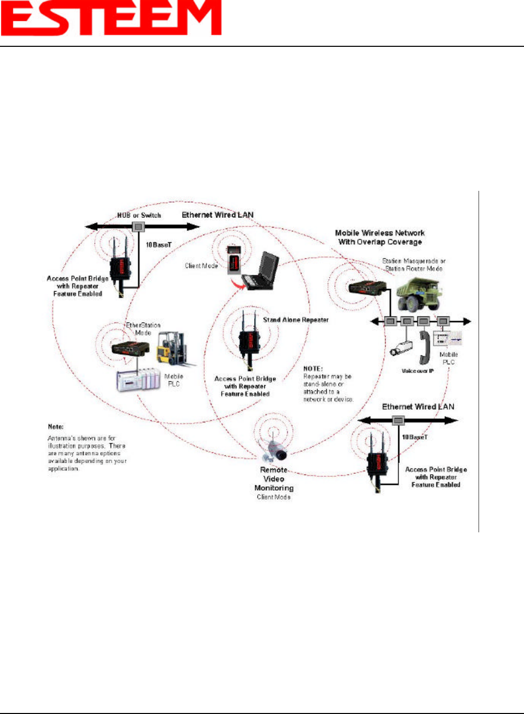
1. Review the Access Point Bridge diagram. See Figure 1.
2. Refer to the top left corner of Figure 1 to the Model 195Eg that is interfaced to the Hub or Switch. This unit is configured as
a wireless Access Point Bridge to the hardwired LAN. In this example the Model 195Eg will have to be programmed in the
Access Point Bridge Mode described in Chapter 1. This Model 195Eg will serve as the base node for 802.11g clients.
3. If you have not defined the IP address of the Model 195Eg then follow the instructions in Chapter 2.
4. Access the ESTeem Web page using your computer’s Web Browser as per instructions in Chapter 3 under Logging On To
the ESTeem Web Configuration Manager.
Figure 1: Access Point Bridge Diagram
CHAPTER 4
CONFIGURATION SETUP
Revised: 25 Jun 04 4-2EST P/N AA107G
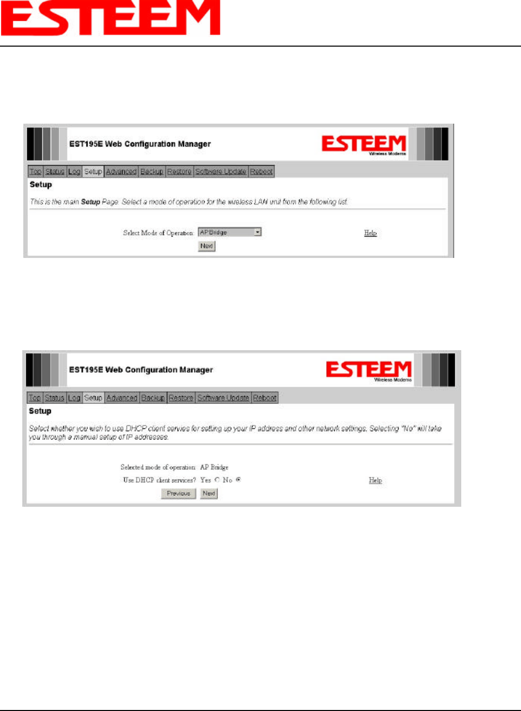
5. From the Model 195Eg Top menu select Setup. From the Select Mode of Operation pull down box , select AP Bridge and
push the Next button below the pull down box. You will now see the screen shown in Figure 2. Note: Throughout the
Configuration Manager are Help Screens that can accessed for further information on each item.
6. Select Yes if you want to use Dynamic Host Configuration Protocol (DHCP) client services. If you want to enter a static IP
address for the Model 195Eg, select No and press the Next button. Reference Figure 3.
Figure 2: Access Point Bridge Setup Screen
Figure 3: DHCP Client Setup Screen
CHAPTER 4
CONFIGURATION SETUP
Revised: 25 Jun 04 4-3EST P/N AA107G
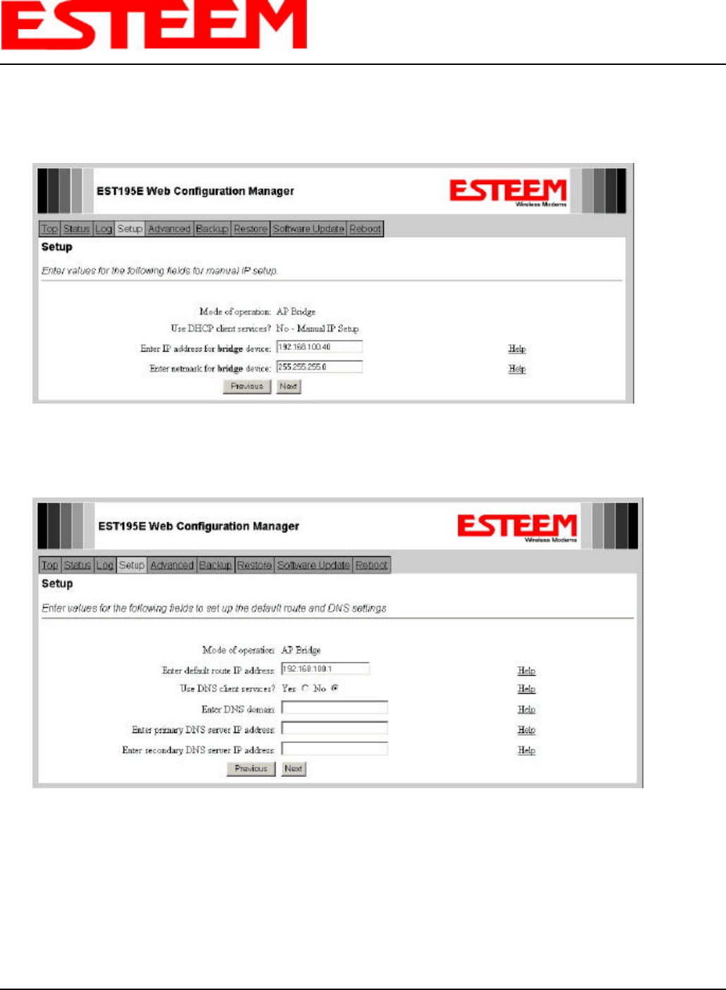
7. Enter the IP Address and IP Netmask for the Model 195Eg. If you want to be able to access the Model 195Eg over the
Ethernet network for diagnostics and updates the IP address must be on the same network as the other Ethernet devices.
Reference Figure 4.
8. Enter the DNS server information. If you are not connecting the Model 195Eg to the Internet, leave blank and press the Next
button. Figure 5.
Figure 4: IP Address Setup Screen
Figure 5: DHCP Setup Screen
CHAPTER 4
CONFIGURATION SETUP
Revised: 25 Jun 04 4-4EST P/N AA107G
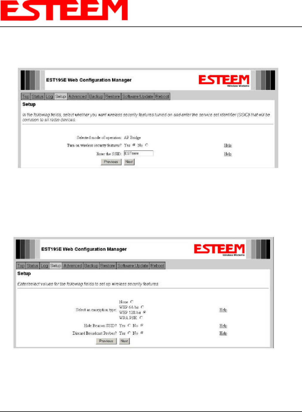
9. Select if you will be using security for your wireless network. Enter the SSID for you 802.11g network. The SSID is the
unique identification for your wireless network and all 802.11g devices that share a wireless network MUST have the same
SSID code. This identification code is case sensitive and must NOT contain spaces. Reference Figure 6.
10. Select the encryption level for the wireless network. If you would like to hide the SSID from broadcasting from the Access
Point select Yes. If Yes is selected the Model 195Eg will not send out periodic SSID radio beacons that can be identified
with 802.11b network scanning software. The users of the network will have to know the SSID to enter the network and
security is increased, but if you want the SSID to be broadcasted to the network for easy identification then select No.
Reference Figure 7.
Figure 6: SSID Setup Screen
Figure 7: Encryption Setup Screen
CHAPTER 4
CONFIGURATION SETUP
Revised: 25 Jun 04 4-5EST P/N AA107G
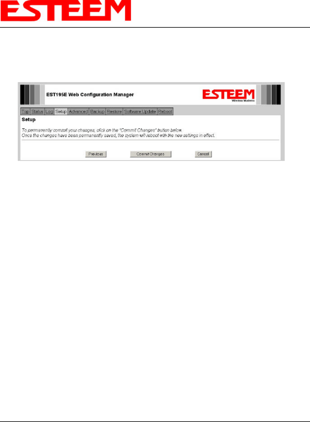
11. Continue through the configuration screens using the Help menus for further questions until you reach the Commit Changes
menu screen. Press the Commit Changes button and Model 195Eg will save your configuration, reboot the unit, and operate
with the commands you have selected. Reference Figure 8.
Figure 8: Commit Changes Menu Screen
CHAPTER 5
REPEATING FEATURES
Revised: 25 Jun 04 5-1EST P/N AA107G
The Repeating Feature in the Model 195Eg is used to
increase the wireless network area of coverage for both
indoor and outdoor applications without the cost of
hardwiring the Access Points to a common LAN. This
custom feature is unique to the Model 195Eg because
conventional 802.11b/g Access Points have to be
interfaced to a common network either by hardwire, see
Figure 1, or a dedicated point to point RF backbone.
When programmed in the Access Point (AP) Repeater Mode, the Model 195Eg will automatically create a wireless network with
other Model 195Eg units in radio range that are programmed in AP Repeater mode and setup with matching configurations.
This feature adds the increased functionality of repeaters to the typical Ethernet Bridge configuration.
AutoRouting
One of the most powerful features of the Repeater
Feature mode is the Model 195Eg’s ability to
automatically calculate all possible
communication routes in the network. The
AutoRoute feature will automatically establish
wireless Ethernet communication paths to each
Model 195Eg that has a matching setup
configuration. This automatic routing greatly
simplifies network configuration and also creates
a “self healing” network by sending data on an
alternate route, if available, upon failure of the
primary path.
AutoRouting Process
Listening Phase. Once a modem is configured
for Access Point Repeater mode and reset, the
Model 195Eg will begin to search out all modems that have a matching configuration setup (SSID, Frequency Channel, AP
Repeater Mode = ON and Security Codes). The first step in the routing process is sending out and listening for “repeater
beacons”. A repeater beacon is a special radio packet that is sent from the Model 195Eg that contains the unit’s MAC address.
When a repeater beacon is received by another Model 195Eg, the MAC address of the originating modem is added to its own
repeater beacons. A route between two Model 195Eg units can be established when they receive a repeater beacon that
contains their own address.
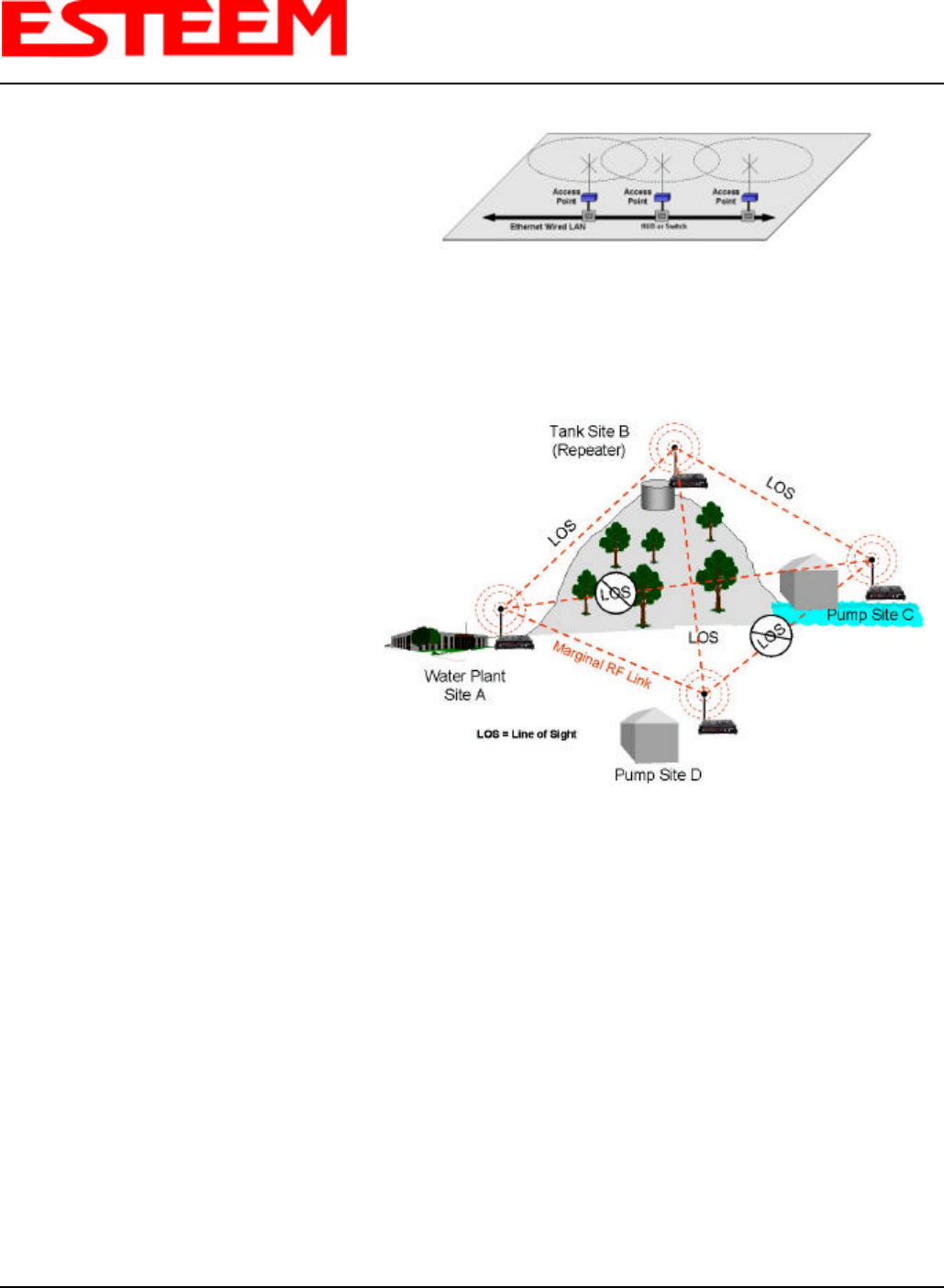
For example let’s look at Figure 2 and the repeater beacons and the route created from Pump Site C and Tank Site B(Repeater).
Pump Site C sends a repeater beacon containing its MAC address over the radio network. The only site that receives this
repeater beacon is Tank Site B (Note – there is no Line-of-sight (LOS) between from Pump Site C to the other sites in the
network). When Tank Site B receives the repeater beacon it adds the MAC address from Pump Site C to its own repeater
beacon and sends it out. This new repeater beacon from Tank Site B (Now containing Pump Site C’s MAC address) is received
at Pump Site C and a route is established. Pump Site C then adds the MAC address for Tank Site B in its repeater beacon, which
is eventually received by Tank Site B.
Repeater beacons will continually be sent from a Model 195Eg every 2 seconds as long as it is configured in AP Repeater mode.
This will allow the Model 195Eg to recognize new sites into the network and any changes to the radio paths. These continued
updates in the repeater beacons give the AP Repeater network the “self-healing” characteristic.
Figure 1: Conventional Access Point Diagram
Figure 2: AP Repeater Diagram

CHAPTER 5
REPEATING FEATURES
Revised: 25 Jun 04 5-2EST P/N AA107G
Learning Phase. After an approximate 10-second period after no further additions to the Mac addresses in the repeater
beacons, the Model 195Eg goes into the learning phase. In this phase all Model 195Eg units calculate their routes to the other
Model 195Eg units in the network using the lowest “path cost”, meaning shortest number of hops, back to the Root Bridge.
Note: The Root Bridge in a network should be the Model 195Eg where the majority of the data flow is processed. In Figure 2,
the Root Bridge will be the Water Plant that is transmitting and receiving data from all three remote sites. The user can program
the Root Bridge manually. If the user does not define the Root Bridge, and if there are multiple candidates for the Route Bridge,
Model 195Eg units in the network will pick the unit with the lowest MAC address. See the following section on Root Bridge for
further details.
Blocking and Forwarding Phase. This last phase in the auto-routing process will eliminate any Ethernet data “loops” that can
double the information received at any remote site. For example, looking at Figure 2, Pump Site D has two routes to the Root
Bridge (Water Plant – Site A). The first Route is direct from the Water Plant and the second Route is via the Tank Site B
(Repeater site). In this example the direct link between the two sites is the shortest route (lowest Path Cost) and will be selected
as the primary route or Forward route. The second route (one with the higher Path Cost) that uses the repeater will be
“Blocked”. All routes to the Root Bridge will be evaluated for the site and be Forwarded or Blocked. The average time to
complete all routing phases in a network is approximately 30 seconds.
Root Bridge
For any Access Point Repeater application that has more than two sites, the user needs to set one of the Model 195Eg’s as the
Root Bridge. The Root Bridge should be the Model 195Eg where the majority of the Ethernet data flow is processed. This site
may be the Master location in a SCADA network or could be configured at a repeater site. Selection is important because, all
the Model 195Eg’s that are “NOT” configured as the Root Bridge will select their routing based upon where the Root Bridge is
defined in the network.
The Root Bridge will be selected in one of two ways:
1. Manually by the users. The Root Bridge can be manually set (recommended) during the configuration at AP Repeater
mode. Reference Chapter 4 – AP Repeater Configuration.
2. Automatically by the Model 195Eg. The Model 195Eg units will automatically configure the Root Bridge by selecting the
lowest MAC address of all the Model 195Eg units in the network. This is usually not recommended in large networks,
because adding a new site to the network could adversely change the entire site’s routing scheme.
If you have any question establishing Route Bridges in your network, contact ESTeem Customer Support at 509-735-9092 or e-
mail your application to support@esteem.com .
CHAPTER 5
REPEATING FEATURES
Revised: 25 Jun 04 5-3EST P/N AA107G
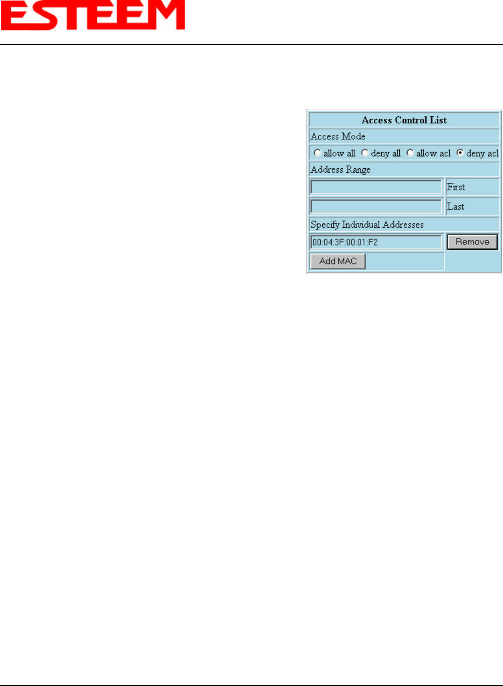
Using the Access Control List (ACL) In Network Design
As mentioned above, the shortest route to the Root Bridge may not be the
best radio path. As seen in Figure 2 the radio path from Pump Site D to the
Water Plant – Site A has a marginal link. Although the shortest route from
Pump Site D to the Water Plant is direct, the best radio path is using the
repeater site at Tank Site B. To force the radio path through the repeater is
as simple as setting the ACL in the Pump Site D Model 195Eg to Deny the
Mac address of the Water Plant. This will force all communications from
Pump Site D to the Water Plant via Tank Site B.
Figure 3: ACL Configuration Example
CHAPTER 6
ANTENNA SETUPS
Revised: 12 Aug 04 6-1 EST P/N AA107G
ANTENNA AND CABLE CONFIGURATIONS
Warning: Only the tested cable lengths and antennas provided by EST meet the FCC maximum peak output power
requirements. Any other combination of antennas or coax cables is not authorized.
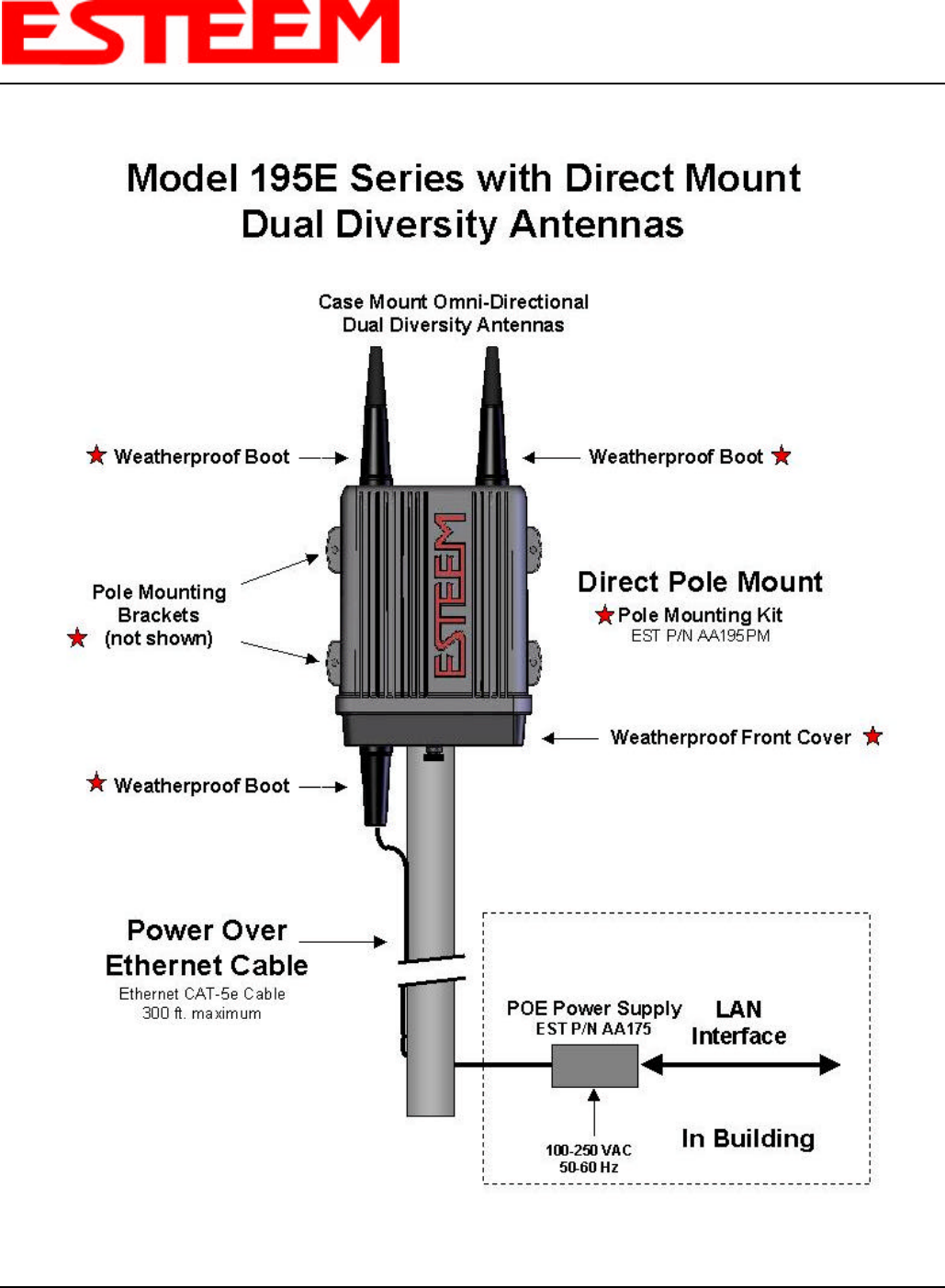
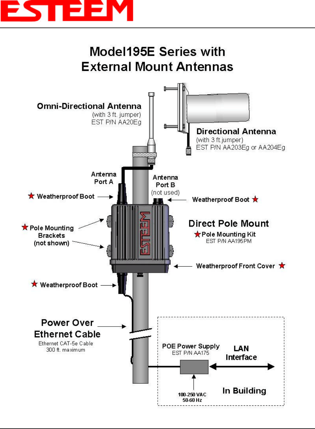
EST offers different types of antennas for both indoor and outdoor configurations.
Part Number: AA01S
• Omni-directional, rubber duck, direct mount, unity
gain antenna.
• Indoors and short range outdoor applications.
• There must be a minimum separation distance of 20
cm. from the antenna to the user. See Warnings.
Part Number: AA20DMg
• Omni-directional direct mount antenna, 3 dBd gain.
• Indoor and outdoor applications.
• There must be a minimum separation distance of 20
cm. from the antenna to the user. See Warnings.
Part Number: AA20Eg
• Omni-directional external pole mount antenna, 6 dBd
gain with 3-ft. integral feedline and connector.
• Outdoor applications.
• Antenna port B is not used in this configuration.
• There must be a minimum separation distance of 20
cm. from the antenna to the user. See Warnings.
Part Number: AA203Eg
• Directional pole mount antenna, 8 dBd gain with 3-ft.
integral feedline and connector.
• Point to point and point to multi-point outdoor
applications.
• Antenna port B is not used in this configuration.
• There must be a minimum separation distance of 20
cm. from the antenna to the user. See Warnings.
Part Number: AA204Eg
• Directional pole mount antenna, 17 dBd gain with 3-ft.
integral feedline and connector.
• Point to point applications only.
• Antenna port B is not used in this configuration.
• There must be a minimum separation distance of 50
cm. from the antenna to the user. See Warnings.
Antenna
Port A
Antenna
Port B
Notes:
Antenna Port A is
a transmit and receive port for use in
all applications.
Antenna Port B is
a receive only port and is used for
dual diversity antennas applications only. This port is
not used for point to point applications.
Warnings:
Only pre-made coax cables from the factory used in
conjunction with either the AA20Eg omni-directional
and AA203Eg or AA204Eg directional antennas meet
all FCC Section 15.247(b) EIRP maximum power
requirements.
Use of the AA204Eg, directional antenna is limited to
fixed point to point applications only. In accordance
FCC Section 15.247(b)iii, the operator or installer is
responsible for ensuring the systems is used exclusively
for fixed, point-to-point applications.
CHAPTER 6
ANTENNA SETUPS
Revised: 12 Aug 04 6-2 EST P/N AA107G
COAXIAL CABLE ATTENUATION
Listed below are representative cable losses in db/100 ft at the 2.4 GHz frequency range:
Feedline Type Attenuation
(dB/100 ft.) @ 2.4 GHz
RG-8 (Solid) 7
LMR 600 4.4
3/8" Heliax 6.5
1/2" Heliax 3.5
7/8" Heliax 2
1.25" Heliax 1.6
Note: A -3 dB loss means you have lost 1/2 of your signal or transmitter power. A +3 dB gain means you have doubled
(x2) your signal or transmitter power.
Example:
A 6 dB antenna will increase the radiated output power of a 1 watt transmitter to 4 watts {times 4 = 3 dB (x2) + 3 dB
(x2)} and increase the received signal strength to receiver times 4
CHAPTER 6
ANTENNA SETUPS
Revised: 12 Aug 04 6-3 EST P/N AA107G
CHAPTER 6
ANTENNA SETUPS
Revised: 12 Aug 04 6-4 EST P/N AA107G
CHAPTER 6
ANTENNA SETUPS
Revised: 12 Aug 04 6-5 EST P/N AA107G
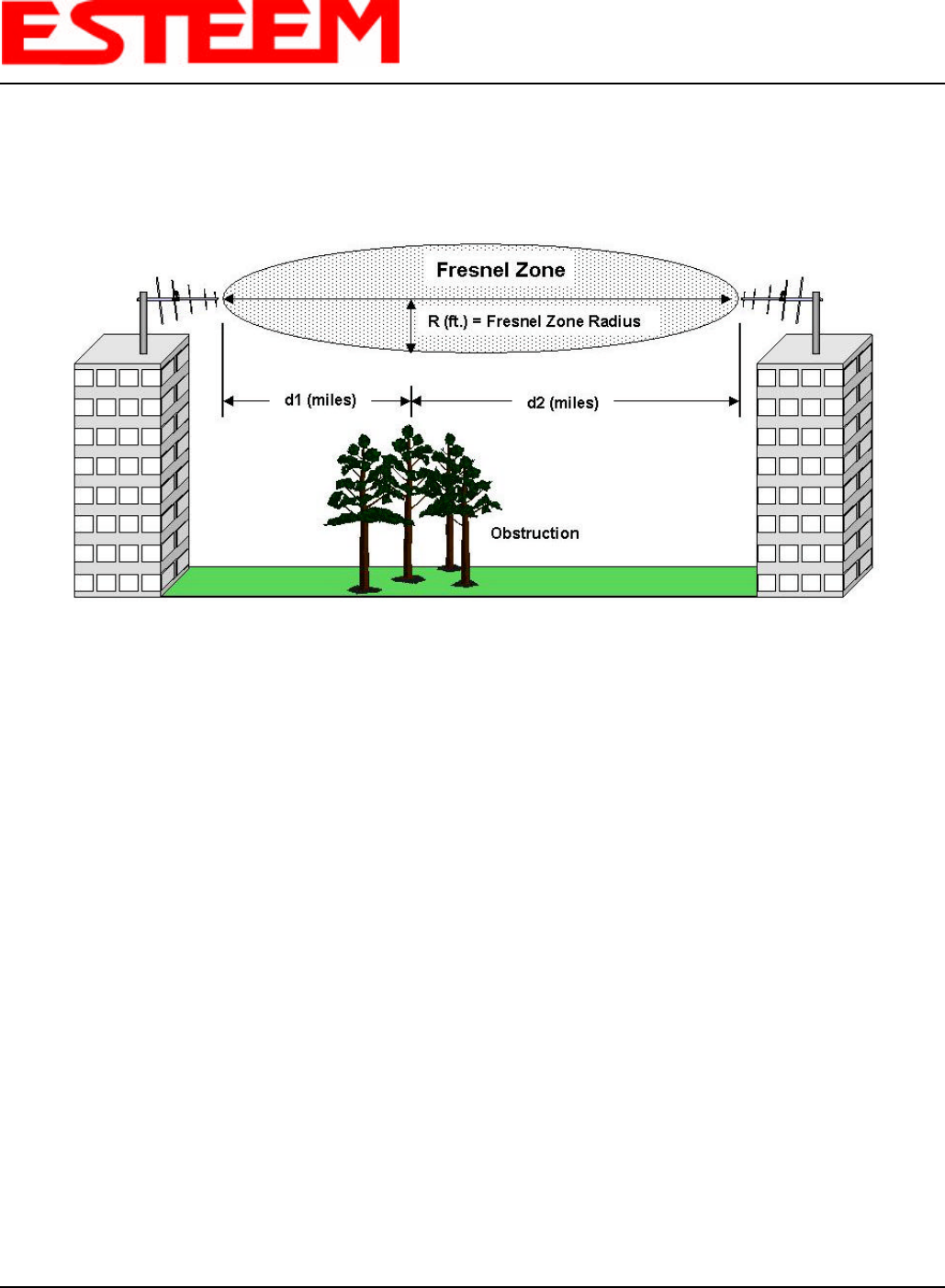
FRESNEL ZONE
The Fresnel zone shows the ellipsoid spread of the radio waves around the visual line-of-sight after they leave the antenna (see
figure above). This area must be clear of obstructions or the signal strength will be reduced due to signal blockage. Typically,
20% Fresnel Zone blockage introduces little signal loss to the link. Beyond 40% blockage, signal loss will become significant.
This calculation is based on a flat earth. It does not take into account the curvature of the earth. It is recommended for RF path
links greater than 7 miles to have a microwave path analysis done that takes the curvature of the earth and the topography of
the terrain into account.
Fresnel Zone Radius = 72.1 SQRT [(d1d2) / (F(d1 + d2)]
Units
Fresnel Zone Radius in feet.
d1 and d2 in statue miles
F in GHz

APPENDIX A
FCC INFORMATION
Revised: 26 Jun 04 APX A-1 EST P/N AA107G
INFORMATION TO USERS
The ESTeem Model 195Eg complies with Part 15 of the
FCC Rules. Operation is subject to the following two
conditions: (1) This device may not cause harmful
interference, and (2) this device must accept any
interference received, including interference that may
cause undesired operation.
Note to User:
Changes or modifications to this equipment not expressly
approved by Electronic Systems Technology for
compliance could void the user's authority to operate the
equipment.
Other Information
Model 195Eg
Direct Sequence
FCC Type Acceptance No: ENPESTEEM195EG
This equipment has been tested and found to comply with the limits for a Class A digital device, pursuant to Part 15 of the
FCC Rules. These limits are designed to provide reasonable protection against harmful interference when the equipment is
operated in a commercial environment. This equipment generates, uses, and can radiate radio frequency energy and, if not
installed and used in accordance with the instruction manual, may cause harmful interference to radio communications.
Operation of this equipment in a residential area is likely to cause harmful interference in which case the user will be
required to correct the interference at his own expense.

APPENDIX A
FCC INFORMATION
Revised: 26 Jun 04 APX A-2 EST P/N AA107G
FEDERAL COMMUNICATIONS COMMISSION FIELD OFFICES
ALASKA
1011 E. Tudor Rd.
Rm 240 Box 2955
Anchorage, AK 99510
CALIFORNIA
Interstate Office Park
4542 Ruffner St., Room 370
San Diego, CA 92111-2216
Los Angeles Office (LA)
Ceritos Corporate Tower
18000 Studebaker Rd., Room 660
Cerritos, CA 90701-3684
San Francisco Office (SF)
5653 Stoneridge Drive, Suite 105
Pleasanton, CA 94588-8543
COLORADO
Denver Office (DV)
215 S. Wadsworth Blvd., Suite 303
Lakewood, CO 80226-1544
FLORIDA
919 Federal Bldg
51 SE First Ave.
Miami, FL 33130
Tampa Office (TP)
2203 N. Lois Ave., Room 1215
Tampa, FL 33607-2356
GEORGIA
Atlanta Office (AT)
3575 Koger Blvd., Suite 320
Duluth, GA 30096-4958
HAWAII
7304 Prince Kuhi
Federal Building
Honolulu, HI
ILLINOIS
Chicago Office (CG)
Park Ridge Office Ctr., Room 306
1550 Northwest Highway
Park Ridge, IL 60068-1460
LOUISIANA
New Orleans Office (OR)
2424 Edenborn Ave. Suite 460
Metarie, LA 70001
MARYLAND
1017 Geo. Fallon
Building 31
Hopkins Plaza
Baltimore, MD
MASSACHUSETTS
Boston Office (BS)
1 Batterymarch Park
Quincy, MA 02169-7495
MICHIGAN
Detroit Office (DT)
24897 Hathaway Street
Farmington Hills, MI 48335-1552
MINNESOTA
691 Federal Building
316 N Robert St.
St. Paul, MN
MISSOURI
Kansas City Office (KC)
520 NE Colbern Road
Second Floor
Lee’s Summit, MO 64086
NEW YORK
1307 Federal Building
111 W. Huron
Buffalo, NY 14202
NEW YORK
New York Office (NY)
201 Varick Street, Suite 1151
New York, NY 10014-4870
OREGON
1782 Federal Building
1220 SW 3rd Avenue
Portland, OR 97204
PENNSYLVANIA
Philadelphia Office (PA)
One Oxford Valley Office Bld.
Room 404
2300 E. Lincoln Hwy
Langhorne, PA 19047-1859
PUERTO RICO
747 Federal Building
Carlo Chardon Ave.
Hato Rey, PR 00918
TEXAS
Dallas Office (DL)
9330 LBJ Freeway, Room 1170
Dallas, TX 75243-3429
5636 Federal Building
515 Rusk Avenue
Houston, TX 77002
WASHINGTON DC
Columbia Office (CF)
9300 East Hampton Drive
Capitol Heights, MD 20743
WASHINGTON
Seattle Office (ST)
11410 NE 122nd Way
Room 312
Kirkland, WA 98034-6927
APPENDIX B
SPECIFICATIONS
Model 195Eg Specifications
Revised: 2 Jul 04 APX B-1EST P/N AA107G
LED Indicators
Power On/Off Receiver On/Off
Carrier Detect On/Off Transmitter On/Off
Link Status On/Off
I/O Connectors
Ethernet 10/100Base T RJ-45
RS-232C Programming Port RJ-45
Dual Antenna input/Outputs TNC Reverse Female
Remote Input Power Power Over Ethernet Cable
Direct Input Power Optional, Header Screw Connector
Transmiter
Frequency of Operation 2.412 to 2.462 GHz
Software Selectable in 11 Channels
RF Data Rates 1,2,5.5,6,9,11,12,18,24,36,48, & 54 Mbps Fixed or Auto Scaling
Tx Output Power 1 Watt
RF Output Impedance 50 ohms
Receiver
Rx Sensitivity -68 dBm @54 Mbps to –89 dBm @ 1 Mbps
Frame Error Rate <10%
Power
Power over Ethernet IEEE 802.3af Standard Power Supply,
48 VDC @ 13 Watts
Power Connector on Unit 10 to 16 VDC
Receive 320 ma @ 12 VDC
Transmit 1000 ma @ 12 VDC
Case
Dimensions 1.9 in. H x 6.7 in. W x 6.2 in. L
Weight 1.25 lbs.
Outdoor Pole Mounting Kit Optional, EST P/N 195PM
Other
Warranty 1 Year
Temperature Range -30° to +60° C
Humidity 95% Non-condensing
FCC Type Acceptance Pending
Industry Canada Type Acceptance Pending
Specifications Subject to Change Without Notice
APPENDIX B
SPECIFICATIONS
Model 195Eg Case Specifications
Revised: 2 Jul 04 APX B-2EST P/N AA107G
APPENDIX B
SPECIFICATIONS
Antenna Specifications
Revised: 2 Jul 04 APX B-3EST P/N AA107G
Model No: AA01S
Antenna Type: Omni-Directional, variable angle rubber duck
Applications:Direct mount
Frequency: 2400 to 2485 MHz
Polarization: Vertical
Impedance: 50 ohms
Gain: Unity
VSWR: < 1.5
Front to Back Ratio: n/a
Horizontal Beamwidth: n/a
Vertical Beamwidth: n/a
Antenna Material: Rubber duct whip.
Mounting Hardware: n/a
Antenna Connector:TNC-R Male
Antenna Envelope: 4.25 in. length by 1.75 in width
Weight: .08 lbs.
Model: AA20DMEg
Applications: Model 195Eg direct case mount
Antenna Type: Omni-Directional, Sleeve dipole
Frequency: 2400 to 2485 MHz
Polarization: Vertical
Impedance: 50 ohms
Gain: 5 dBi (3 dBd)
VSWR: < 2:1
Power: 10 W
Front To Back Ratio: n/a
Horizontal Beamwidth: n/a
Vertical Beamwidth: n/a
Antenna Material: Polyurethane Plastic Radome
Recommended Mounting Hardware: n/a
Antenna Connector: TNC-R Male
Flexibility: +/- 20 °
Antenna Envelope: 8.28 in. length by .54 in. width
Temperature: -40 to +70 C°
Weight: 33 grams
Model AA01S
Model AA20DMEg
Caution
Omni-directional antenna
should not be located within
20 cm of personnel.
Caution
Omni-directional antenna
should not be located within
20 cm of personnel.
APPENDIX B
SPECIFICATIONS
Antenna Specifications
Revised: 2 Jul 04 APX B-4EST P/N AA107G
Model No: AA20Eg
Antenna Type: Omni Directional, DC Grounded
Applications:Fixed base
Frequency: 2400 to 2483.5 MHz
Polarization: Vertical
Impedance: 50 ohms
Gain: 4dBd (6 dBi)
VSWR: < 1.5
Front to Back Ratio: n/a
Horizontal Beamwidth: n/a
Vertical Beamwidth: 20 degrees @ ½ power
Antenna Material: Copper alloy radiator, UV inhibited
fiberglass enclosed
Mounting Hardware: Aluminum bracket for mounting
to 1 ¼ to 2 in. diameter mast included.
Antenna Connector:TNC-R Male with 36in. pig-tail.
Antenna Envelope: 11.6 in. length by 1.25 in. diameter
Weight: .4 lbs.
Mounting Bracket
Model AA20Eg
Caution
To comply with the FCC
exposure compliance
requirements, a separation
distance of at least 20 cm
must be maintained between
the antenna and all persons.
APPENDIX B
SPECIFICATIONS
Antenna Specifications
Revised: 2 Jul 04 APX B-5EST P/N AA107G
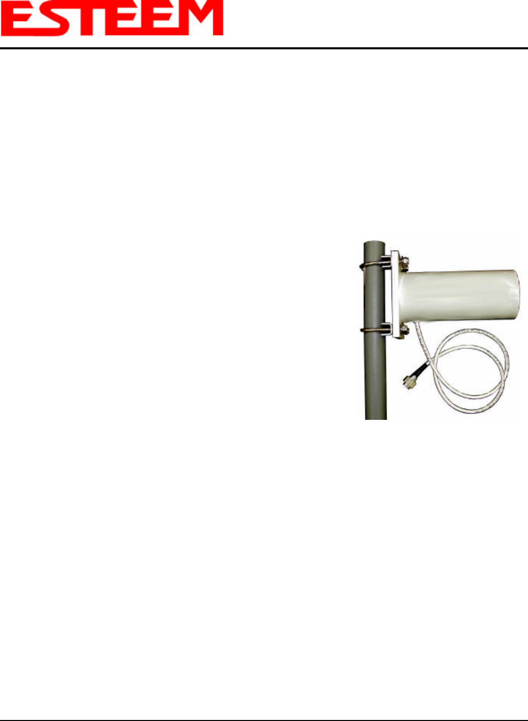
Model No: AA203Eg
Antenna Type: Directional, DC grounded
Applications:Fixed base.
Frequency: 2400 to 2485 MHz
Polarization: Vertical or Horizontal
Impedance: 50 ohms
Gain: 8 dBd (10 dBi)
VSWR: < 1.5
Front to Back Ratio: 23 dB
Horizontal Beamwidth: 55 degrees @ ½ power
Vertical Beamwidth: 55 degrees @ ½ power
Antenna Material: Sealed in UV stable fiberglass enclosed radome
Mounting Hardware: Stainless steel U bolts (included) for mounting up
to 1 5/8 in. diameter pipe.
Antenna Connector:TNC-R Male with 36in. pig tail
Maximum Power Input: 5 Watts
Antenna Envelope: 4.5 in. length by 3 in. diameter
Windload (RWV): 125 mph
Lateral Thrust at
Rated Wind: 5.8 lbs.
Wind Surface Area: 0.060 ft2
Weight: 1 lbs.
Model AA203Eg
Caution
To comply with the FCC
exposure compliance
requirements, a separation
distance of at least 20 cm
must be maintained
between the antenna and all
persons.
APPENDIX B
SPECIFICATIONS
Antenna Specifications
Revised: 2 Jul 04 APX B-6EST P/N AA107G
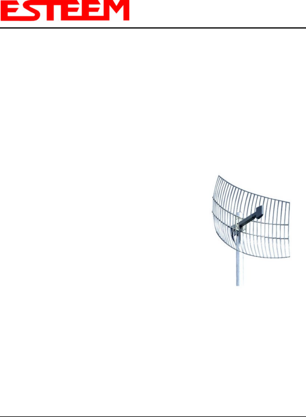
Model No: AA204Eg
Applications: Fixed base mounting
Antenna Type: 2.4 GHz ISM, Directional, DC Grounded, Parabolic Grid
Frequency: 2400-2485 MHz
Polarization: Vertical or Horizontal
Impedance: 50 ohms
Gain: 17 dBd (19 dBi) nominal
VSWR: < 1.5:1 nominal
Front to Back Ratio: >24 dB
Horizontal Beamwidth:16 degrees @ ½ power
Vertical Beamwidth: 11 degrees @ ½ power
Antenna Material: Zinc plated cold rolled steel with polyester power
coat finish
Recommended Mounting
Hardware: Standard U-bolt steel mast clamp complete with
mounting hardware. Designed for masts of up to
2.5 in. O.D.
Antenna Connector:TNC-R Male with 36 in. pig-tail
Maximum Power Input: 10 Watts
Wind Survival: 100 mph
Wind Load: 16 mph
Antenna Envelope: 34 in. length by 17 in. width by 11 in. height
Weight: 3 lbs.
Model AA204Eg
Caution
To comply with the FCC exposure
compliance requirements, a
separation distance of at least 50 cm
must be maintained between the
antenna and all persons.
Use of the AA204Eg, directional antenna is limited to fixed point to point applications only. In accordance FCC
Section 15.247(b)iii, the operator or installer is responsible for ensuring the systems is used exclusively for
fixed, point-to-point applications.