Elpas Solutions 5-HLA00125 HANDHELD LOW FREQUENCY EXCITER User Manual
Elpas Solutions Ltd. HANDHELD LOW FREQUENCY EXCITER Users Manual
Users Manual
Page 1 of 8
V15/March 11
www.visonictech.com
Elpas Handheld LF Exciter
Part Number: 5-HLA00125 Configuration & User Guide
Introduction
The Elpas Handheld LF Exciter (HHLF) from is an ultra-miniature,
LF Exciter designed for acute care hospitals, geriatric/nursing
care facilities or pediatric units. The device provides on-duty
healthcare personnel with an effective, low-cost, easy-to-use tool
for performing ad-hoc patient/asset match and association tests,
canceling nurse/patient-calls or for triggering entrance or exit
monitoring applications.
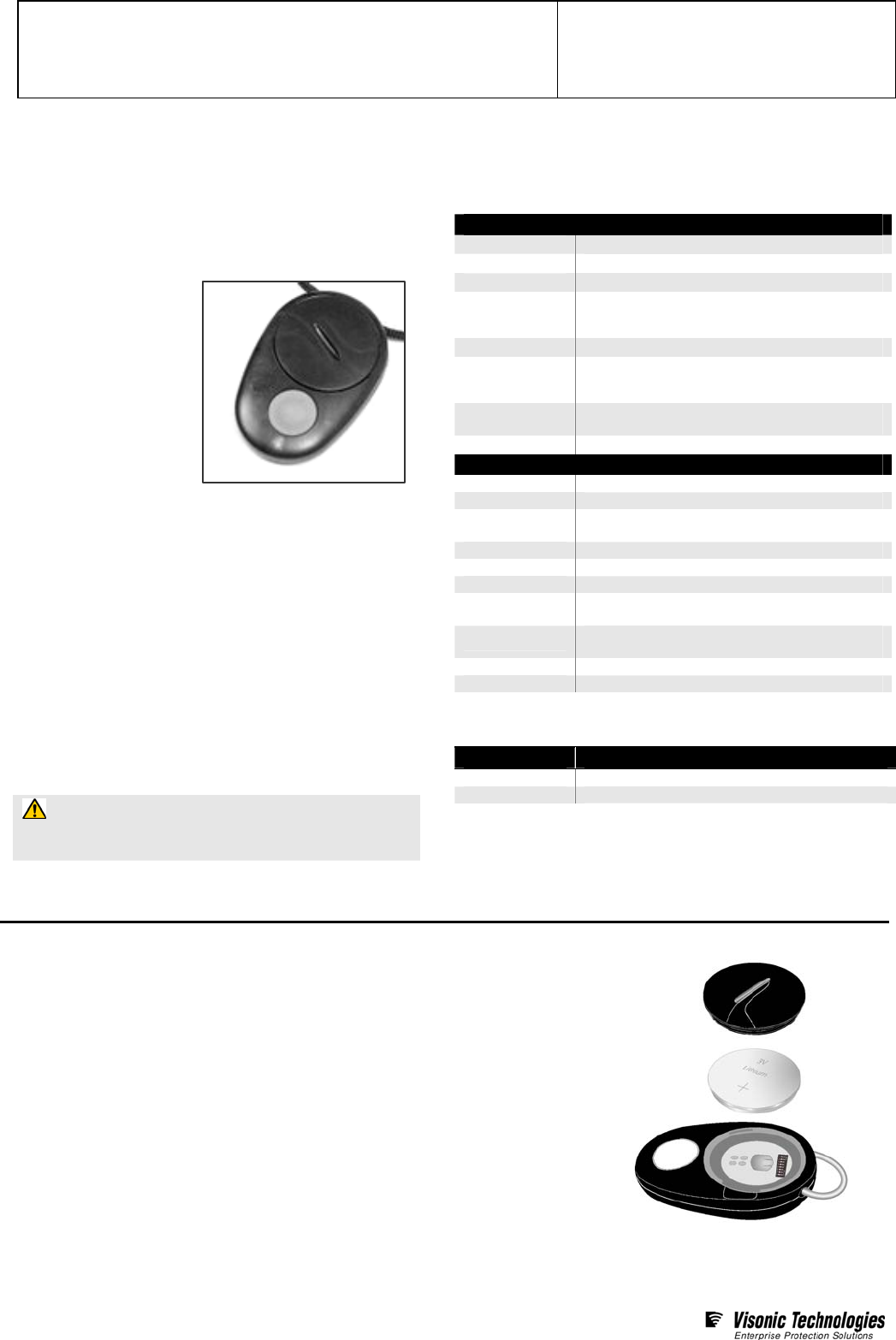
The Elpas Handheld LF
Exciter emits a harmless,
low power; sphere shaped
magnetic (125 KHz) field
whenever its large oversized
button is pressed. Thus
whenever a staff member
pushes the exciter’s button
within a 0 - 30cm (0.0 to
11.8 inches)* radius of a
patient/asset bearing an
Elpas active RFID tag, the
exciter will trigger the mobile
tag to immediately transmit
data messages. The data is instantly detected, interpreted and
relayed by the legacy Elpas RF reader infrastructure as required
in support of the configured medical application.
Worn as a neck lanyard, the Handheld LF Exciter is enclosed in a
shower proof, IP-64 water-rated black ABS outer housing.
Powered by a single commercially available lithium battery (CR-
2430 or equivalent), the LF Exciter provides approximately three
years of service before needing replacement. The device is
shipped with a pre-attached neck lanyard and one lithium battery.
*NOTES:
1 The effective range of the LF field may vary due to the relative
orientation of the exciter to the tag/badge.
2 The HHLF will generate the LF field only as long as the ‘Operation’
button remains constantly pressed.
3 Elpas tags and/or badges manufactured prior to January 2009 are not
designed to properly operate with the Handheld LF Exciter.
CAUTION: It is important that you read, understand,
and follow the instructions in this document. If you have
questions, call your local VT support representative.
\
Technical Specifications
Electrical
Field Technology 125KHz, Low frequency electromagnetic fields
Power Source Lithium 3V / 900mA (CR 2430 or equivalent)
Battery Life 3 years (typical usage)
Red LED
Indicator
Constant: Button press
Flashing (once per sec.): Improper ID address
Flashing (every 0.5 sec.): Low battery condition
Output Format 3 byte messages
LF Field Range From 0 to 30cm (0.0 to 11.8 inches) radius
Range may vary due to the relative orientation of
the exciter to the tag/badge
LF Transmission
Rate Continuous bursts of LF emissions while button is
pressed (each about 12ms in duration)
Exciter ID code Set by on-board 8 position DIP-switch
General
Construction Black, ABS plastic
Housing IP64 water rated enclosure
Dimensions
(H x W x D) 34mm x 40mm x 15mm
(1,3 inches x 1.6 inches x 0.6 inches)
Weight 40g (1.4 ounces.) including lanyard & battery
Operational Temp 0°C to 50°C (32°F to 122°F)
Humidity 80% maximum, non-condensing
Remote
Management Eiris 4.5 Software (or higher)
CE Standards EN 300 330-1, EN-301 489-1, EN-301 489-3,
EN50130-4, IEC 60950-1, EN 60950-1
FCC & IC FCC: O4X5-HLA00125……IC: 1467G-HLA00125
Warranty One year limited warranty
Ordering Information
Part # Description
5-HLA00125 Handheld LF Exciter
5-PBA90003 3V/600mAh Lithium Battery, CR2450 (25 pcs)
Battery Replacement
The HHLF normally provides about 3 years of continuous use. Should the device fail to
generate a LF field or behaves unpredictably, replace the battery. This typically solves most
problems.
1. Purchase a new 3V lithium battery (CR2430). Then temporarily disable the HHLF in the
EIRIS software.
2. Place a coin in the slot of the battery cover. Turn the coin anti-clockwise as far as you can;
the cover will become slightly raised.
3. Remove the cover; take out the worn-out battery from the HHLF and dispose of it in line
with local ordinances.
4. Position a new battery with the positive (+) side up and reposition the battery cover.
5. Place a coin in the slot of the battery cover and turn clockwise as far as you can until you
hear a click confirming closure. Finally, using EIRIS, .re-enable the HHLF.
Elpas Handheld LF Exciter – Configuration & User Guide
Page 2 of 8
V15/March 11
www.visonictech.com
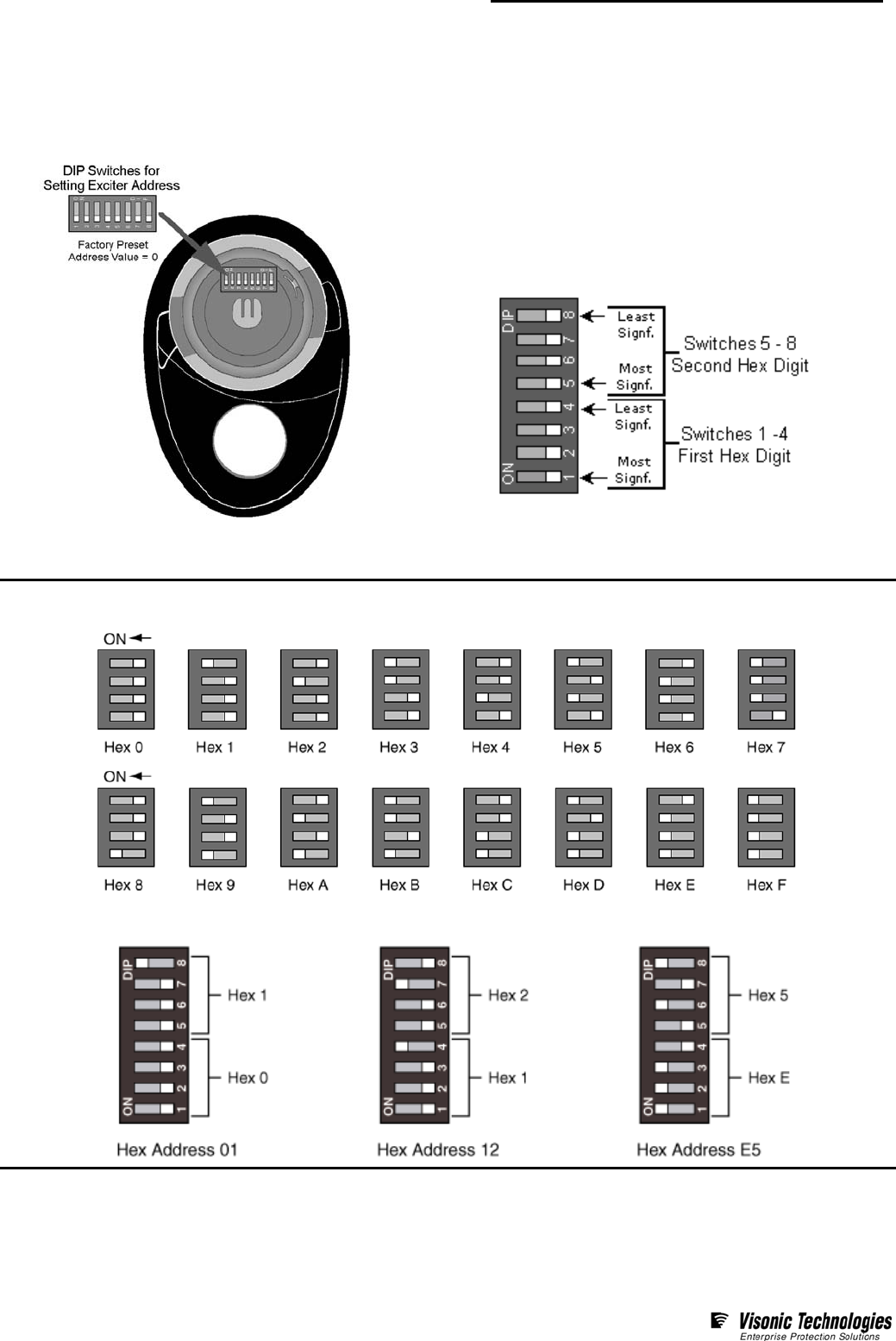
ID Address Setup
Each Handheld LF Exciter must be assigned a unique ID Address (Neuron ID Number) in order for EIRIS to identify the device. It is vital
that the ID Address assigned to a HHLF does not conflict with the ID Address of any other fixed or handheld LF exciters already
registered in the EIRIS database.
Each HHLF is shipped from the factory with all 8 DIP switches set to
OFF. Remove the battery from the HHLF. Then use the DIP
switches to set the device’s ID address.
The ID address is configured using a binary coded hexadecimal
number. Switches 1-4 (high nibble) are used to set the first
hexadecimal digit while switches 5-8 (low nibble) are used to set the
second hexadecimal digit.
Together, the two hexadecimal digits provide a total of 256
possible ID addresses.
The figure below shows how to set the hex digitals ‘0’ to ‘F’
Below are three examples of addresses set in hexadecimal:
NOTE: Certain ID Addresses are not acceptable and should avoid being used on any HHLF. These addresses are: 13, 35, 4B, 4D, 5C, B8,
D5 and DC. If any unacceptable addresses are used, the exciter’s red LED indicator will continually flash plus its intended cancel
functionality will not work.
Elpas Handheld LF Exciter – Configuration & User Guide
Page 3 of 8
V15/March 11
www.visonictech.com
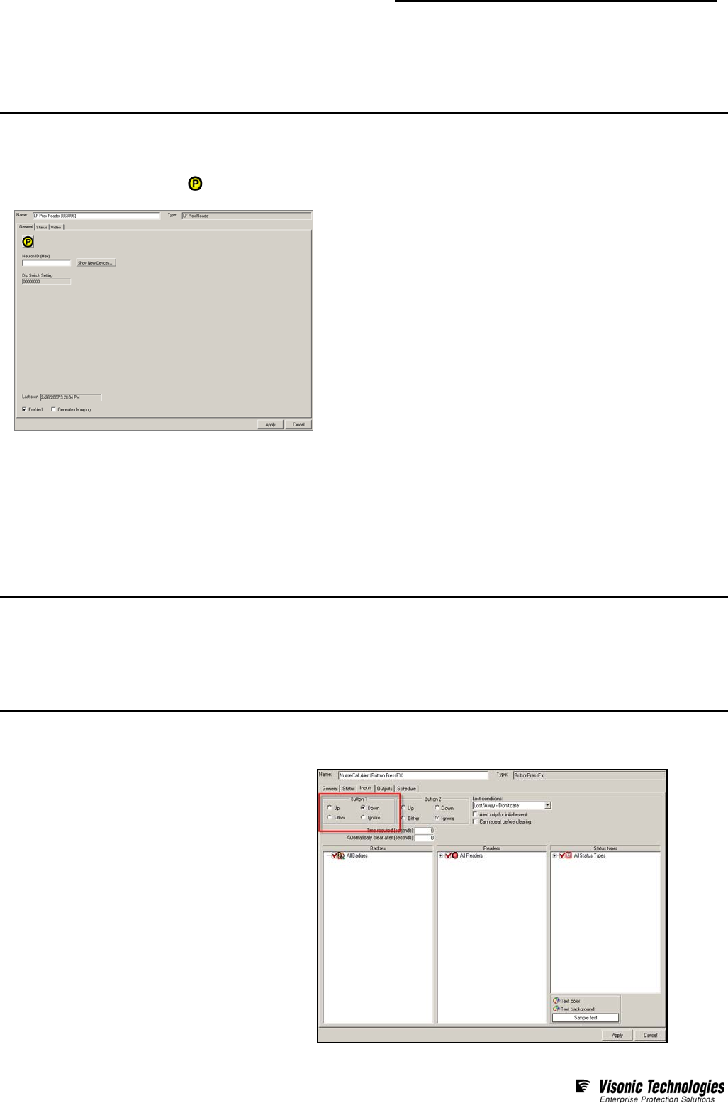
HHLF Registration in EIRIS
Prior to configuration, each Handheld LF Exciter needs to be registered in the EIRIS database using the device’s Neuron ID Number in
order to make it possible for EIRIS to recognize the device. Ensure that the ID address assigned to each HHLF does not conflict with
the ID address of any other fixed or handheld LF exciters in the system.
1. Start the EIRS Server; launch EV2 and access Setup mode.
2. Access the Components tab in the Object Tab pane. Right-click on the All Readers branch of the component tree; Select Add By Type; the
Add Object box appears.
3. Select the Elpas LF Prox Reader icon and press Add; a new Elpas LF prox reader sub-branch (with default name) appears in the
components tree. Additionally, the corresponding Elpas LF Prox Reader configuration form appears.
4. On the General tab, update the Name of the HHLF so
that it will stand for the device’s intended usage as described below:
• For Nurse Call Cancellation: The name of the HHLF matches the
caregiver that is issued the device.
• For Baby Tag/HHLF Match Tests: The name of the HHLF
represents the mother that is issued the devices.
• For Baby Tag/Mother Tag Match Tests: The name of the HHLF
matches the caregiver that is issued the device.
5. Enter the Neuron ID Number (the hexadecimal digits) that corresponds to
the ID address of the selected HHLF.
6. Press Apply; the registration details of the selected HHLF are saved to the
EIRIS database.
Using the Handheld LF Exciter to Cancel a Nurse Call
Elpas healthcare tags are often used as wireless, portable patient call-buttons in healthcare and assisted living environments. When a
patient/resident summons assistance using their assigned Elpas tag, EIRIS will immediately display and trigger the applicable visual
and audible call indicators as well as the relevant messaging options. EIRIS continues generating these call-indicators and messaging
options till the patient-call is closed by the responding caregiver using the HHLF remotely at the patient’s actual location. This type of
localized nurse call cancellation is accomplished by having the caregiver press the call-cancellation button on their assigned HHLF
during the time actual assistance is being rendered. Upon receipt of the call cancellation event, EIRIS will close the call, record the
identity of the responding caregiver and generate a time-stamp documenting the point-in-time assistance was provided.
Prerequisites
Before configuring EIRIS to support nurse call cancellation using the HHLF, verify that the following software prerequisites are satisfied:
• Make sure that the NurseCall.dll (Nurse Call extension) is installed in the EIRIS Extensions folder
(typically: C:\Eiris\e41srv\Data\Extensions) and that a proper license for the extension has been acquired.
• Register the needed Handheld LF Exciters in the EIRIS database. Ensure that the chosen Names of the HHLFs match the caregivers
that will use them.
Configuration Procedure
To configure EIRIS so that a Handheld LF Exciter can be used to cancel a nurse call, you will need to define a Nurse Call and HHLF
Cancellation alert as well as the subsequent Cancel Auto-Action.
Step 1 - Define a Nurse Call Alert
1. Using the ButtonPressEX Alert, on the Inputs form
select the Button 1 Down option.
2. Select the following Input components options:
• All patient/resident tags
• All Readers
• All Status Types
3. Define the Clients, Outputs & Alert Messages as
required.
Elpas Handheld LF Exciter – Configuration & User Guide
Page 4 of 8
V15/March 11
www.visonictech.com
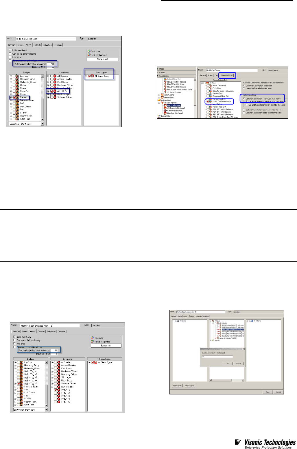
Step 2- Define an HHLF Cancellation Alert
1. Using the Location Alert, on the Inputs form select
All Patient Tags, All HHLFs & all Status Types.
2. Enter 10 in the ‘Automatically Close After’ value field.
Step 3 - Define a Call Cancel Auto-Action
1. Configure an HHLF Call Cancel auto-action to close the
Nurse Call alert when a HHLF Call Cancel Alert is triggered.
2. Using the Calls form; select the Nurse Call Alert in the Call
Alerts list pane.
3. Using the Cancellation form select the HHLF Call Cancellation
Alert in the Cancellation Alerts list pane.
4. Enable the Call & Cancellation IDs Must Match option. This
ensures that if multiple Nurse Call Alerts are open, the responding
nurse will only close the related patient call.
Having Mothers Perform Match Tests using the Handheld LF Exciter
EIRIS has long supported Mother/Baby match tests. In this usage scenario, each new mother is given a HHLF that has been pre-
matched to the specific Elpas Infant Protection Bracelet that was affixed to her baby at the time of birth. Random Match Tests can
be performed whenever deemed necessary by simply having the mother press the match-test button on her assigned HHLF while
she is with the baby in question. EIRIS will automatically validate whether or not the mother is in fact with the correct baby. If the
match test is successful, (the mother is with the correct baby), the green lamp of a nearby visual indicator (such as the Elpas Signal
Tower) immediately illuminates for approximately 10 seconds. Should the match test fail, (the mother is with a baby other then her
own) the red lamp of the visual indicator will illuminate for approximately 10 seconds.
Configuration Prerequisites
Before configuring EIRIS to support mother initiated Mother/Baby Match Tests using the HHLF, verify that the following software
prerequisites are satisfied:
• Make sure that the BadgeMatch.dll (Badge Match extension) is in the EIRIS Extensions folder
(typically: C:\Eiris\e41srv\Data\Extensions) and that a proper license for the extension has been acquired.
• Register the needed Handheld LF Exciters into the EIRIS database. Ensure that the chosen Names of the HHLFs can easily
represent the particular mothers that will use them.
Configuration Procedure
To configure the Handheld LF Exciter so that it can be used to perform Mother/Baby Match, it will be essential that separate, Success
and Failure alerts be defined for each of the corresponding Baby Tag/HHLF pairs. Consequently, if twenty (20) different Baby
Tag/HHLF pairs are registered in EIRIS, then 20 of each alert type must also be defined.
Step 1- Define a Success Alert
1. Using the Location Alert, on the Inputs form select the
specific Baby Tag and the specific HHLF that the alert is
for. Also choose All Status Types.
2. Enter 10 in the ‘Automatically Close After’ time value field.
3. On the Outputs form, select the Success Outputs that
will trigger the green lamps on the related visual indicators.
4. Double-click on the chosen Success Outputs and for each
one, set the output duration to 10 seconds.
5. Repeat Steps 1-4 for each additional Baby Tag/HHLF pair.
Elpas Handheld LF Exciter – Configuration & User Guide
Page 5 of 8
V15/March 11
www.visonictech.com
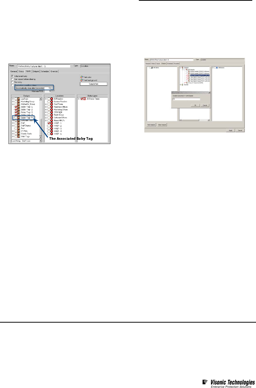
Step 2- Define a Failure Alert
The Failure alert is the same as the Success Alert except that you
select all the other baby tags and not the associated baby tag.
1. Using the Location Alert, on the Inputs form select all the
non-associated baby tags and the specific HHLF that this
failure alert is for. Also choose All Status Types.
2. Enter 10 in the ‘Automatically Close After’ time value field.
3. On the Outputs form, select the Failure Outputs that will
trigger the red lamps on the corresponding visual indicators.
4. Double-click on the chosen Failure Outputs and for each
one, set the output duration to 10 Seconds.
5. Repeat Steps 1-4 for each additional Baby Tag/HHLF pair.
Directing Test Results to Specific Rooms
The above configuration procedure is designed to have EIRIS first validate whether or not the mother is in fact with the correct baby and
second trigger the correct green or red lamps on the installed visual indicators. In other words, if a number of visual indicators are installed
throughout the facility, they will all simultaneously indicate the results of the match tests regardless of where they are.
Should it prove necessary to segregate the outputs such that each room has its own visual indicator, then the following Elpas hardware,
EIRIS software extension and EIRIS alerts are needed:
• Each room must be equipped with an Elpas IR reader with local processing, an Elpas External Box (EXB) and a visual indicator (such
as an Elpas Signal Tower).
• Using the optional Elpas Extension (since it supports the ability to associate LF exciters with particular IR or RF readers) combined
HHLF/IR locations need to be defined for each room in EIRIS.
• Additionally, subsequent Success and Failure alerts need to be defined for each room in EIRIS.
Having Caregivers Perform Match Tests using the Handheld LF Exciter
In this scenario, upon admission to the maternity unit, each mother-to-be is issued an Elpas tag (such as a Healthcare Positioning
Tag) that a companion relationship has been pre-defined in EIRIS with the Elpas Infant Protection Bracelet that is-to-be affixed to
her baby at birth. Random Match Tests can be performed by simply having a caregiver press the match-test button on his/her HHLF
while physically within a 40cm/1.3ft radius of the baby in question; making sure that the baby’s tag was excited by seeing that the
green lamp of the nearby visual indicator (such as the Elpas Signal Tower) flashes for about two seconds. Within 5 seconds, the
caregiver repeats this procedure near the mother, again making sure that the mother’s tag was excited by seeing that the green
lamp again flashes for about two seconds.
EIRIS will immediately validate whether or not the mother is in fact with the correct baby. If the match test proves successful, (the
mother is with the correct baby), the green lamp of the visual indicator will illuminate for approximately 10 seconds. Should the
match test fail, (the mother is with a baby other then her own) the red lamp will light for about 10 seconds.
Configuration Prerequisites
Before configuring EIRIS to support caregiver initiated Mother/Baby Match Tests using the HHLF, verify that the following software
prerequisites are satisfied:
• Make sure that the BadgeMatch.dll (Badge Match extension) is installed in the EIRIS Extensions folder (typically:
C:\Eiris\e41srv\Data\Extensions) and that a proper license for the extension have been acquired.
• Register the needed Handheld LF Exciters (HHLFs) in the EIRIS database. Ensure that their chosen Names can easily symbolize the
particular caregivers that will use them.
Elpas Handheld LF Exciter – Configuration & User Guide
Page 6 of 8
V15/March 11
www.visonictech.com
Configuration Procedure
To configure EIRIS so that a Handheld LF Exciter can be used by a caregiver to perform random match tests, you will first need to
define companion relationships between the appropriate mother tags and the corresponding baby tags. Then you will need to define
the subsequent Confirmation, Success and Failure alerts.
Step 1- Associate the Mother with the Baby
1. Access the Companions tab of the Badgematch
Configuration form. Select the Mother Tag you want to
associate a ‘Companion’ with; then click Add Companions.
2. Select the Baby Tag that is to be the ‘Companion’ to the
chosen mother tag.
Step 2- Define a Confirmation Alert
1. Using the Location Alert, on the Inputs form select
All Baby Tags, All Mother Tags and all HHLFs .Also
choose All Status Types.
2. Enter 10 in the ‘Automatically Close After’ time value field.
3. On the Outputs form, select the Confirmation Outputs
that will trigger the green lamps of the visual indicators.
4. Double click on the selected Outputs and for each, set the
output duration to 2 Seconds.
Step 3- Define a Success Alert
This alert is only enabled when the match test proves successful.
1. Using the Location Alert, on the Inputs form, select
All Baby Tags, All HHLFs. Also choose All Status Types.
2. On the Outputs form, select the Success Outputs that will
trigger the green lamps on the related visual indicators.
3. Double-click on the chosen Success Outputs and for each
set the output duration to 10 Seconds.
4. On the Override form, define/enable the Parameters or
Options as detailed below.
Elpas Handheld LF Exciter – Configuration & User Guide
Page 7 of 8
V15/March 11
www.visonictech.com
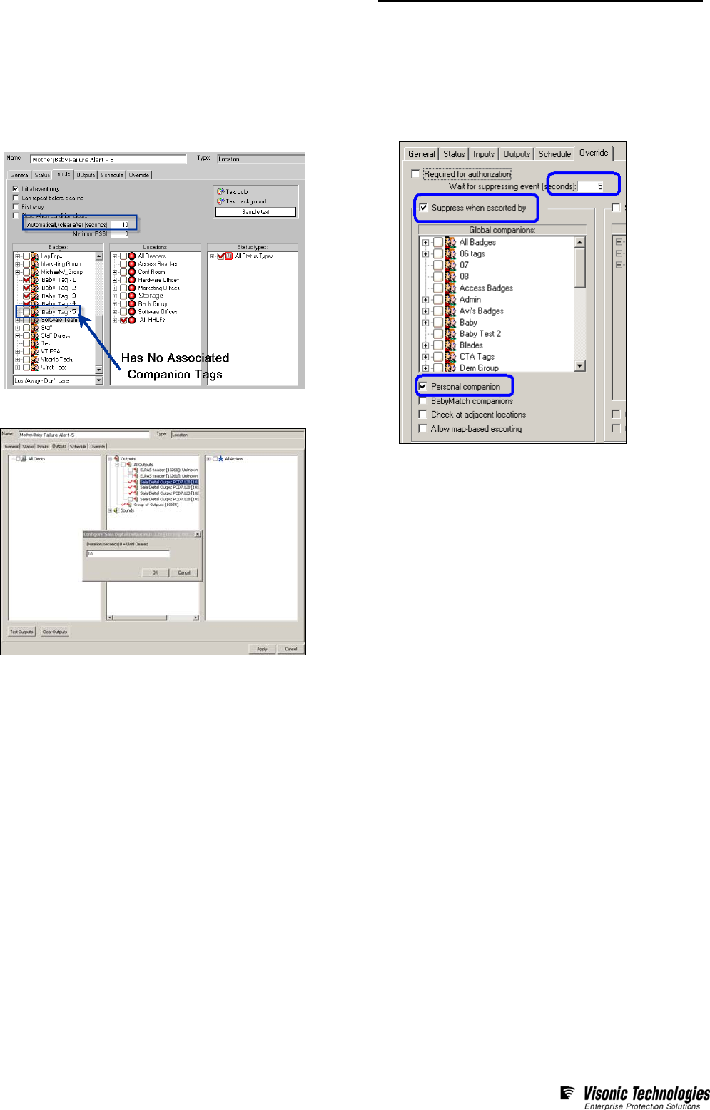
Step 4- Define a Failure Alert
This alert is only enabled for all baby tags except the related
companion baby tag.
1. Using the Location Alert, on the Inputs form select the
Baby Tags that’ have no associated Companions,’ and
All HHLFs. Also choose All Status Types.
2. On the Outputs form, select the Failure Outputs that will
trigger the red lamps on the related visual indicators.
3. Double-click on the chosen Failure Outputs and for each set
the output duration to 10 Seconds.
4. On the Override form, define/enable the Parameters
or Options as detailed below.
Directing Test Results to Specific Rooms
The above configuration procedure is designed to have EIRIS
first validate whether or not the mother is in fact with the correct
baby and second trigger the correct green or red lamps on the
installed visual indicators. In other words, if a number of visual
indicators are installed throughout the facility, they will all
simultaneously indicate the results of the match tests regardless
of where they are.
Should it prove necessary to segregate the outputs such that
each room has its own visual indicator, then the following Elpas
hardware, EIRIS software extension and EIRIS alerts are needed:
• Each room must be equipped with an Elpas IR reader with
local processing, an Elpas External Box (EXB) and a visual
indicator (such as an Elpas Signal Tower).
• Using the optional Elpas Extension (since it supports the
ability to associate LF exciters with particular IR or RF
readers) combined HHLF/IR locations need to be defined for
each room in EIRIS.
• Additionally, subsequent Success and Failure alerts need to
be defined for each room in EIRIS.

Elpas Handheld LF Exciter – Configuration & User Guide
Page 8 of 8
V15/AMarch 11
W.E.E.E. Product Recycling Declaration
For information regarding the recycling of this product you must contact the company from which you orignially purchased it.
If you are discarding this product and not returning it for repair then you must ensure that it is returned as identified by your supplier.
This product is not to be thrown away with everyday waste. Directive 2002/96/EC Waste Electrical and Electronic Equipment.
www.visonictech.com
Standards Compliance
This device complies with Part 15 of the FCC Rules and RSS-210 of
Industry and Science Canada. Operation is subject to the following two
conditions: (1) This device may not cause harmful interference, and (2)
this device must accept any interference received, including
interference that may cause undesired operation.
This device complies with Industry Canada license-exempt RSS
standard(s). Operation is subject to the following two conditions: (1) this
device may not cause interference, and (2) this device must accept any
interference, including interference that may cause undesired operation
of the device.
Le présent appareil est conforme aux CNR d'Industrie Canada
applicables aux appareils radio exempts de licence. L'exploitation est
autorisée aux deux conditions suivantes : (1) l'appareil ne doit pas
produire de brouillage, et (2) l'utilisateur de l'appareil doit accepter tout
brouillage radioélectrique subi, même si le brouillage est susceptible
d'en compromettre le fonctionnement.
Warning!
Visonic Technologies is not responsible for any radio or TV interference
caused by unauthorized modifications to this equipment. Such
modifications could void the user’s authority to operate the equipment.
Product Warranty
Visonic Technologies Ltd. (VT or the Company), and its affiliates,
warrants its products (hereinafter referred to as "the Product”) to be free
of defects in materials and workmanship under normal operating
conditions and use for a period of one year from the date of shipment
by VT. The Company’s obligations shall be limited within the warranty
period, at its option, to repair or to replace the defective Product or any
defective component or part thereof. To exercise this warranty, the
product must be returned to the manufacturer freight prepaid and
insured.
This warranty does not apply to repairs or replacement caused by
improper installation, Product misuse, failure to follow installation or
operating instructions, alteration, abuse, accident, tampering, repair by
anyone other than VT, external causes, and failure to perform required
preventive maintenance. This warranty also does not apply to any
products, accessories, or attachments used in conjunction with the
Product, including batteries, which shall be covered solely by their own
warranties, if any. VT shall not be liable for any damage or loss
whatsoever, whether directly, indirectly, incidentally, consequentially or
otherwise, resulting from a malfunction of the Product due to products,
accessories, or attachments of others, including batteries, used in
conjunction with the Product.
VT MAKES NO EXPRESS WARRANTIES EXCEPT THOSE STATED
IN THIS STATEMENT. VT DISCLAIMS ALL OTHER WARRANTIES,
EXPRESS OR IMPLIED, INCLUDING WITHOUT LIMITATION IMPLIED
WARRANTIES OF MERCHANTABILITY AND FITNESS FOR A
PARTICULAR PURPOSE. VT’S SOLE RESPONSIBILITY FOR
WARRANTY CLAIMS IS LIMITED TO REPAIR OR TO REPLACE AS
SET FORTH IN THIS STATEMENT.
VT shall have no liability for any death, personal injury, property
damage, or other loss whether direct, indirect, incidental, consequential,
or otherwise, based on a claim that the Product failed to function.
However, if VT is held liable, whether directly or indirectly, for any loss
or damage arising under this limited warranty or otherwise, regardless
of cause or origin, VT's maximum liability shall be limited to the
purchase price of the Product, which shall be fixed as liquidated
damages and not as a penalty, and shall be the complete and exclusive
liability of VT.
VT shall not, under any circumstances whatsoever, be liable for any
inaccuracy, error of judgment, default, or negligence of VT, its
employees, officers, agents, or any other party, or of the purchaser or
user, arising from any assistance or communication of any kind
regarding the configuration, design, installation, or creation of security
system involving the Product, that being the responsibility of the
purchaser or user.
If VT is unable to make such repair or replacement, VT’s entire liability
shall be limited to the cost of a reasonable substitute product. VT shall
not be responsible for any dismantling, installation, reinstallation,
purchasing, shipping, insurance, or any similar charges.
VT shall have no liability for any damages, including without limitation,
any direct, indirect, incidental, special, or consequential damages,
expenses, costs, profits, lost savings or earnings, or other damages
arising out of the use of the Product or the removal, installation,
reinstallation, repair or replacement of the Product or any related
events. In the event that there is any liability against VT, such liability
shall be limited to the purchase price of the Product which amount shall
be fixed as liquidated damages.
The purchaser and user understand that this Product may be
compromised or circumvented by intentional acts; that the Product will
not in all cases prevent death, personal injury, property damage, or
other loss resulting from burglary, robbery, fire or other causes; and that
the Product will not in all cases provide adequate warning or protection.
The purchaser and user also understand that a properly installed and
maintained alarm may reduce the risk of events such as burglary,
robbery, and fire without warning, but it is not insurance or a guarantee
that such events will not occur or that there will be no death, personal
injury, property damage, or other loss as a result of such events.
By purchasing the Product, the purchaser and user shall defend,
indemnify and hold VT, its officers, directors, affiliates, subsidiaries,
agents, servants, employees, and authorized representatives harmless
from and against any and all claims, suits, costs, damages, and
judgments incurred, claimed, or sustained whether for death, personal
injury, property damage, or otherwise, because of or in any way related
to the configuration, design, installation, or creation of a security system
involving the Product, and the use, sale, distribution, and installation of
the Product, including payment of any and all attorney’s fees, costs,
and expenses incurred as a result of any such events.
The purchaser or user should follow the Product installation and
operation instructions and test the Product and the entire system at
least once each week. For various reasons, including but not limited to
changes in environmental conditions, electric, electronic, or
electromagnetic disruptions, and tampering, the Product may not
perform as expected. The purchaser and user are advised to take all
necessary precautions for the protection and safety of persons and
property.
This statement provides certain legal rights. Other rights may vary
by state or country. Under certain circumstances, some states or
countries may not allow exclusion or limitation of incidental or
consequential damages or implied warranties, so the above exclusions
may not apply under those circumstances and in those states or
countries.
VT reserves the right to modify this statement at any time, in its sole
discretion without notice to any purchaser or user. However, this
statement shall not be modified or varied except by VT in writing, and
VT does not authorize any single individual to act on its behalf to modify
or vary this statement .
Any questions about this statement should be directed to VT. 3/0