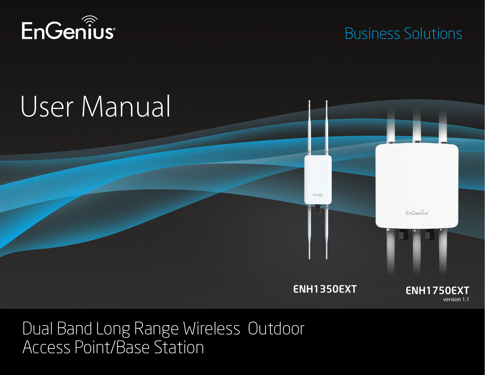
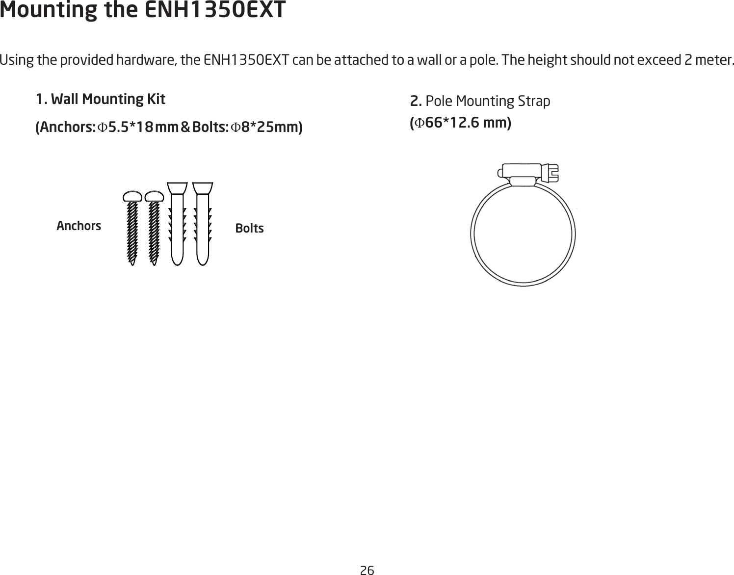
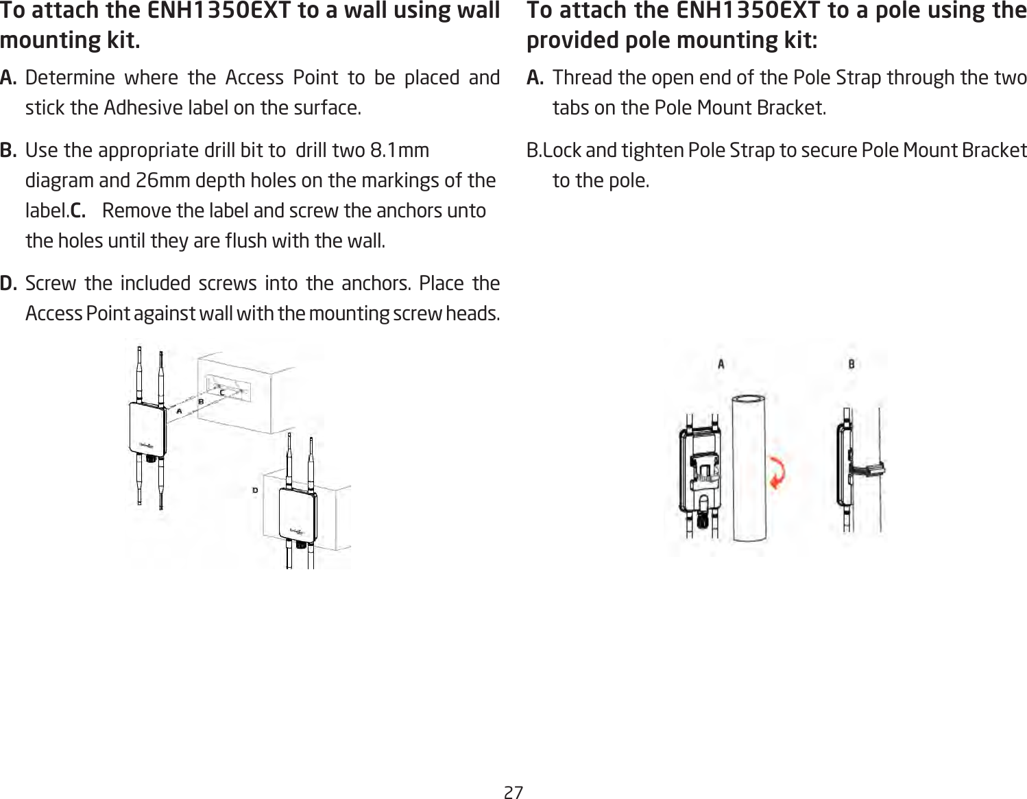
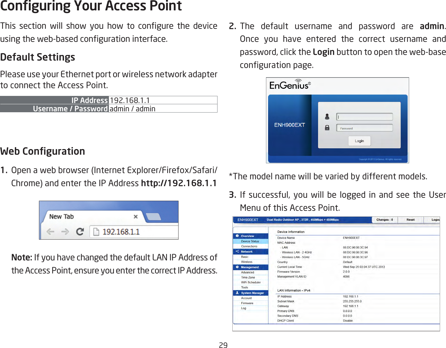
EnGenius Technologies ENH1350EXT Outdoor Long Range Wireless Access Point User Manual
EnGenius Technologies Outdoor Long Range Wireless Access Point
UserManual.wiki
>
EnGenius Technologies
>
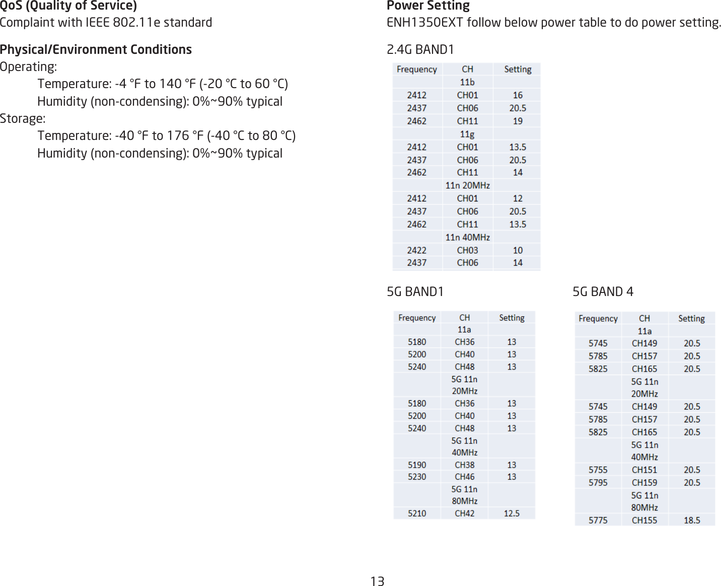
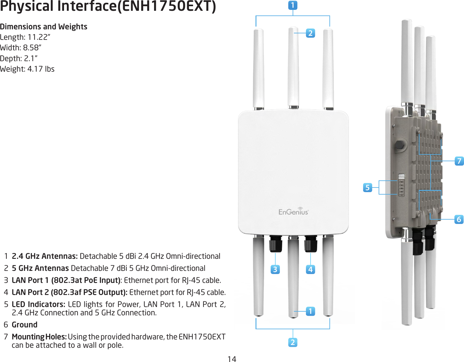
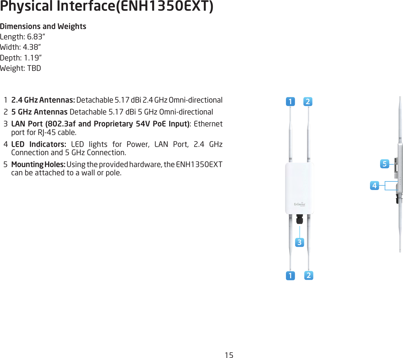
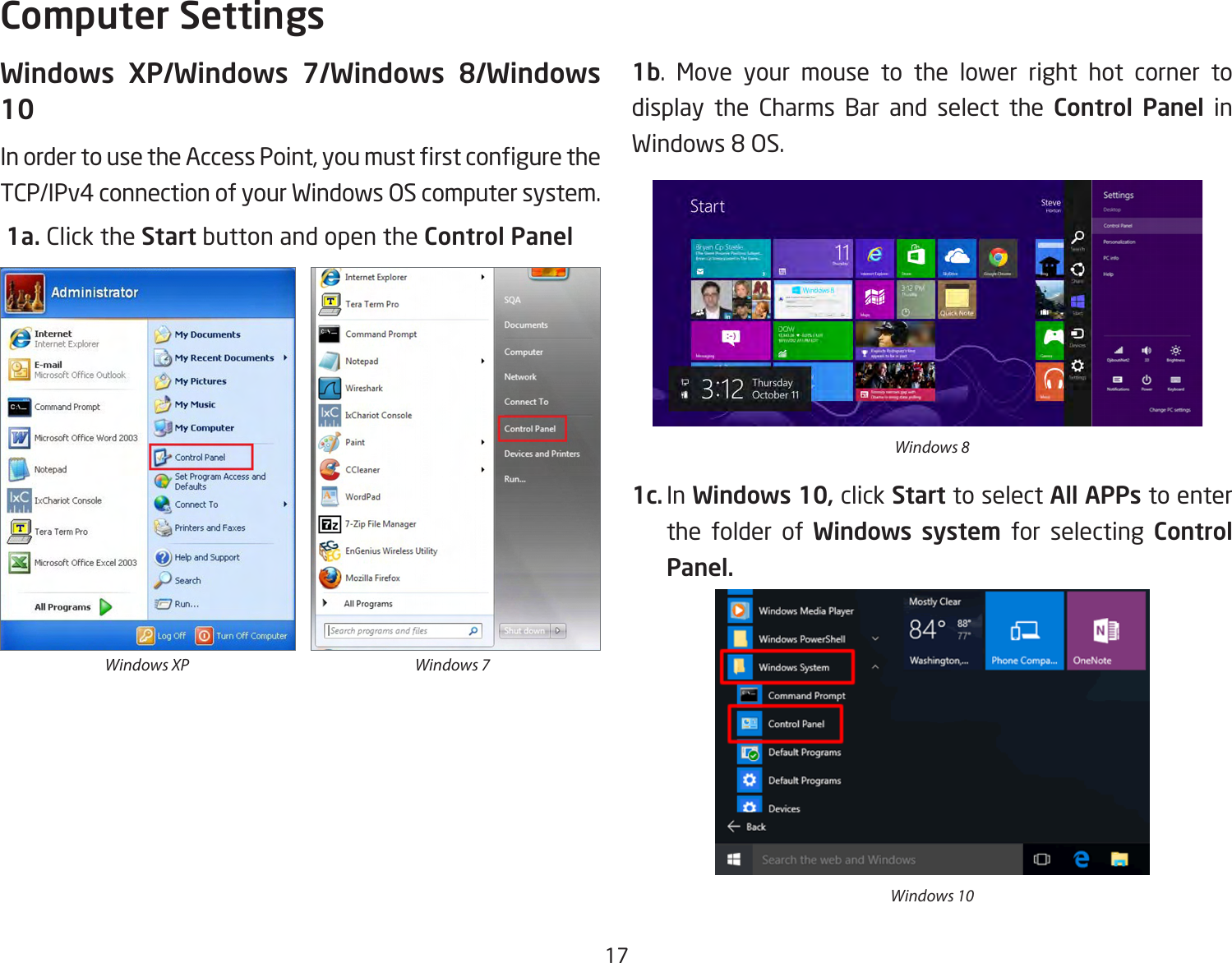
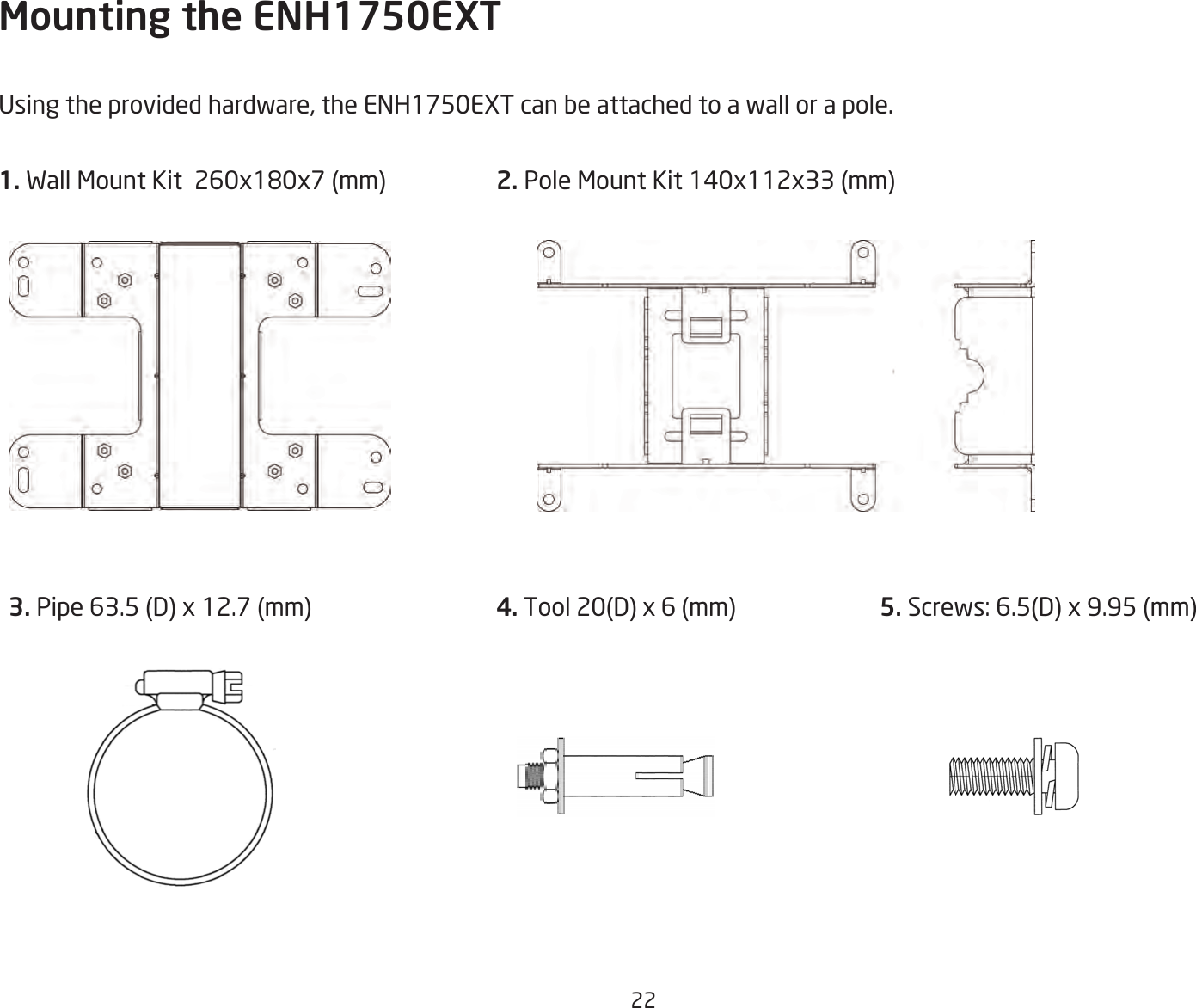
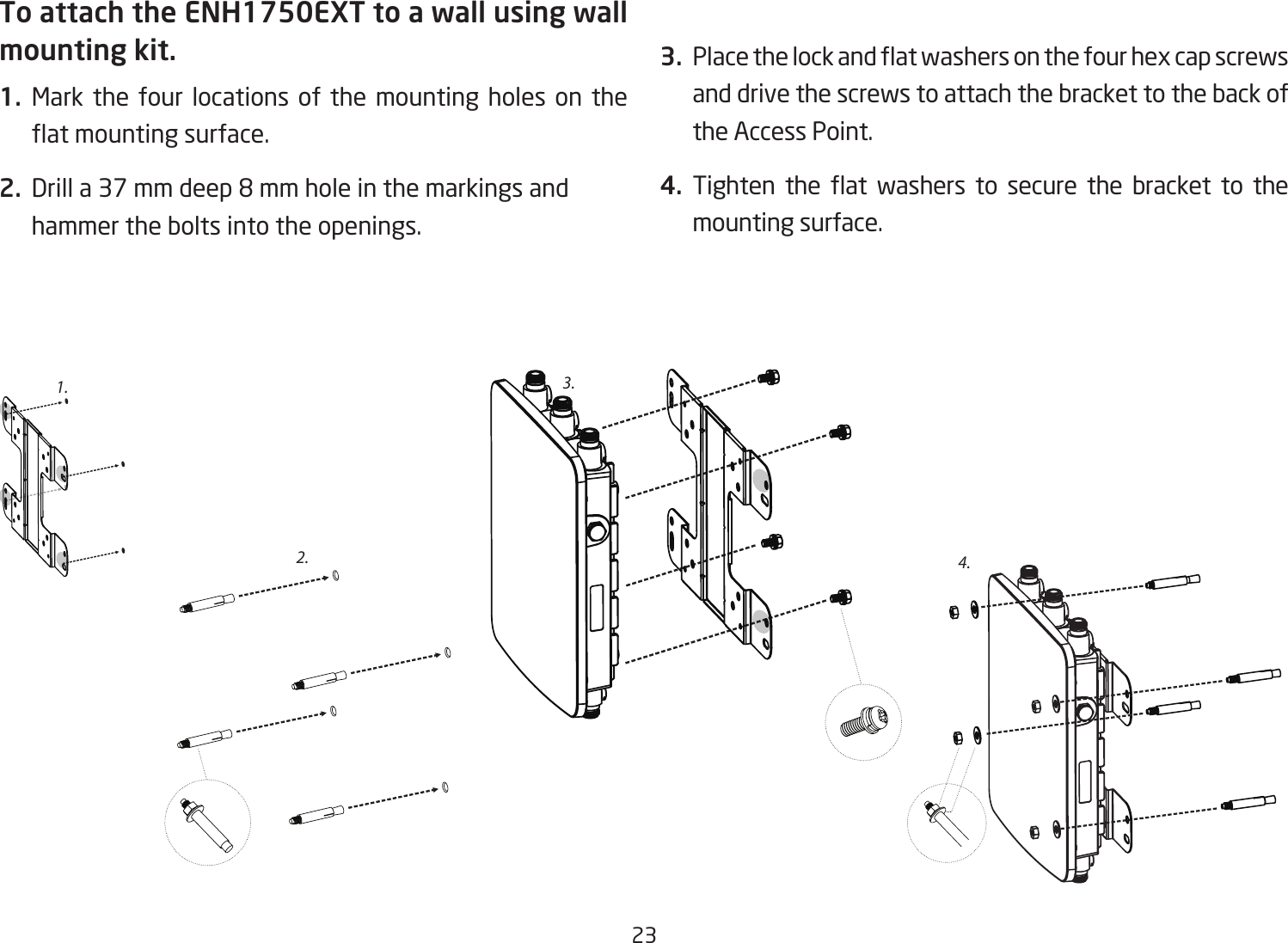
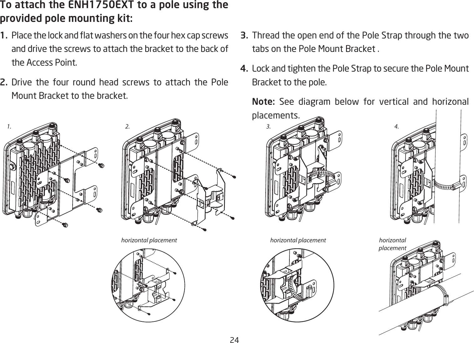
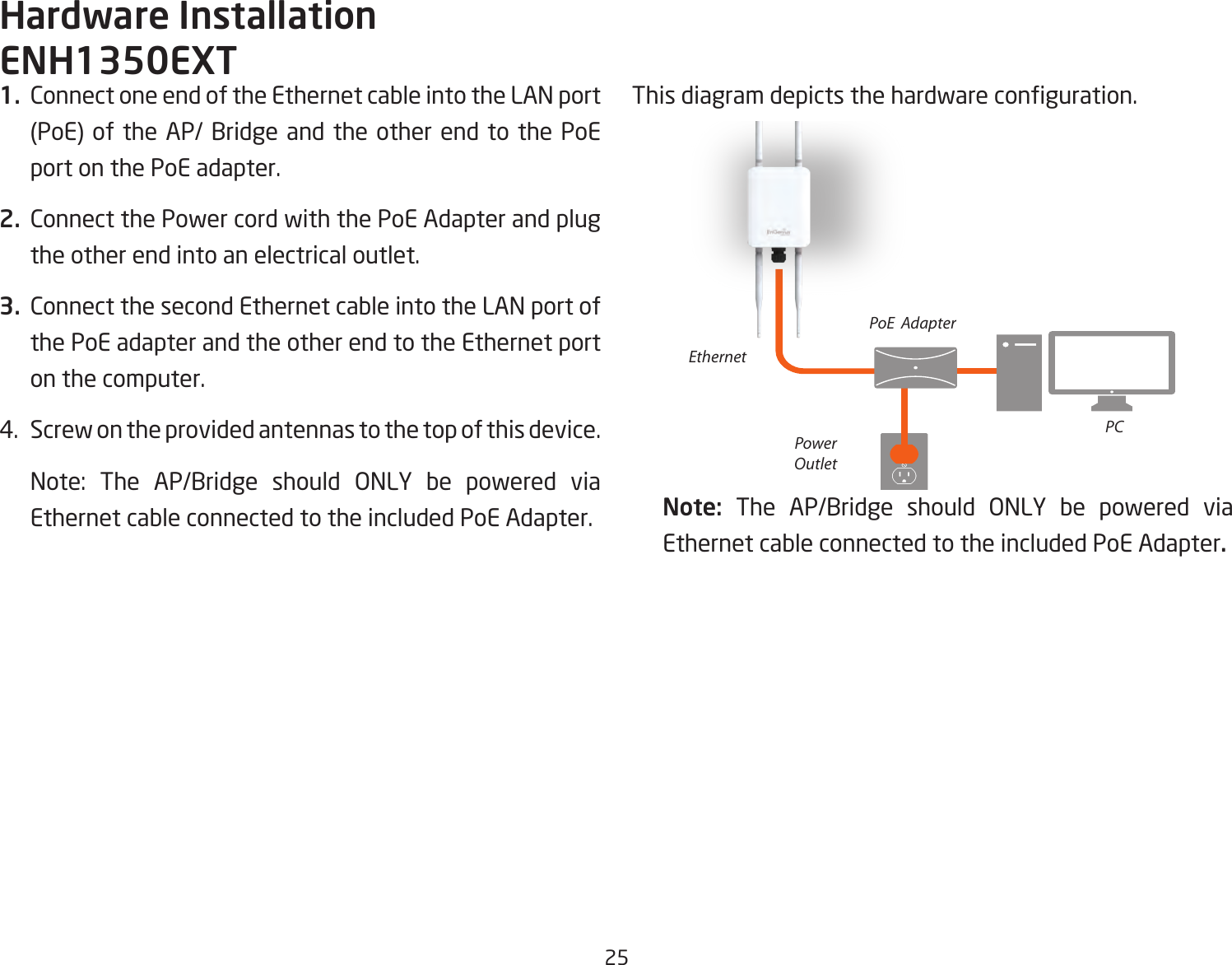
ENH1350EXT User Manual
User Manual
Navigation menu
Upload a User Manual
Namespaces
Wiki Guide
HTML
PDF
Info
Views
User Manual
Discussion / Help
Navigation