EnGenius Technologies ENH1350EXT Outdoor Long Range Wireless Access Point User Manual
EnGenius Technologies Outdoor Long Range Wireless Access Point
User Manual
User Manual
Business Solutions
Dual Band Long Range Wireless Outdoor
Access Point/Base Station
ENH1750EXT
version 1.1
ENH1350EXT
2
IMPORTANT
To install this Access Point please refer to the
Quick Installation Guide included in the product packaging.
3
Chapter 1 Product Overview...................................................................... 4
ENH1750EXT
Key Features/Introduction........................................................ 5
System Requirements............................................................... 6
Package Contents......................................................................... 7
ENH1350EXT
Key Features/Introduction........................................................ 8
System Requirements............................................................... 9
Package Contents......................................................................... 9
Technical Specications....................................................................10
Physical Interface..........................................................................14
Chapter 2 Before You Begin.................................................................... 16
Computer Settings............................................................................. 17
ENH1750EXT
Hardware Installation.................................................................. 21
Mounting the AP.......................................................................... 22
ENH1350EXT
Hardware Installation................................................................. 25
Mounting the AP...........................................................................26
Chapter 3 Conguring Your Access Point............................................28
Default Settings./Web Conguration.......................................... 29
Chapter 4 Building a Wireless Network............................................... 30
Access Point ........................................................................................ 31
Clien Bridge Mode............................................................................... 32
WDS AP Mode..................................................................................... 33
WDS Bridge Mode...............................................................................34
WDS Station Mode......................................................................,.. ...35
AP Mesh Mode.....................................................................................36
Mesh Only Mode.......................................................................... .....37
Chapter 5 Status..........................................................................................38
Overview..................................................................................... ..........39
Connection........................................................................................... 42
Chapter 6 Network ................................................................................... .44
Basic IP Settings..................................................................................45
Spanning Tree Protocol Setting....................................................46
Chapter 7
2.4 GHz/5 GHz Wireless.....................................................................47
Wireless Settings............................................................................... .48
2.4 GHz/5 GHz Wireless Network.................................................49
Wireless Security..................................................................................50
Wireless Trafc Shaping.................................................................. 53
Fast Roaming.........................................................................................54
Mesh Settings-ENH1750EXT........................................................ 55
Guest Network Settings.................................................................. 56
Wireless MAC Filteing.........................................................................58
Wireless Advanced.............................................................................. 59
Chapter 8 Management ............................................................................... 60
Management VLAN Settings......................................................... 61
Advanced Settings............................................................................. 62
CLI Settings/Email Alert....................................................................63
Time Zone..............................................................................................65
Auto Reboot Settings..................................................................... .66
Wi-Fi Scheduler....................................................................................67
Tools........................................................................................................ 68
Account/Firmware...............................................................................70
Backup/Restore ..................................................................................71
Log.............................................................................................................73
Logout/Reset.......................................................................................74
Appendix..............................................................................................................75
FCC Interference Statement...........................................................76
IC Interference Statement..............................................................77
CE Interference StatEment.............................................................79
Professional installation instruction...........................................80
Table of Contents

4
Chapter 1
Product Overview
5
Maximum data rates are based on IEEE 802.11 standards. Actual throughput and range may vary depending on many factors including environmental conditions, distance between
devices, radio interference in the operating environment, and mix of devices in the network. Features and specications subject to change without notice. Trademarks and registered
trademarks are the property of their respective owners. For United States of America: Copyright © 2014 EnGenius Technologies, Inc. All rights reserved.
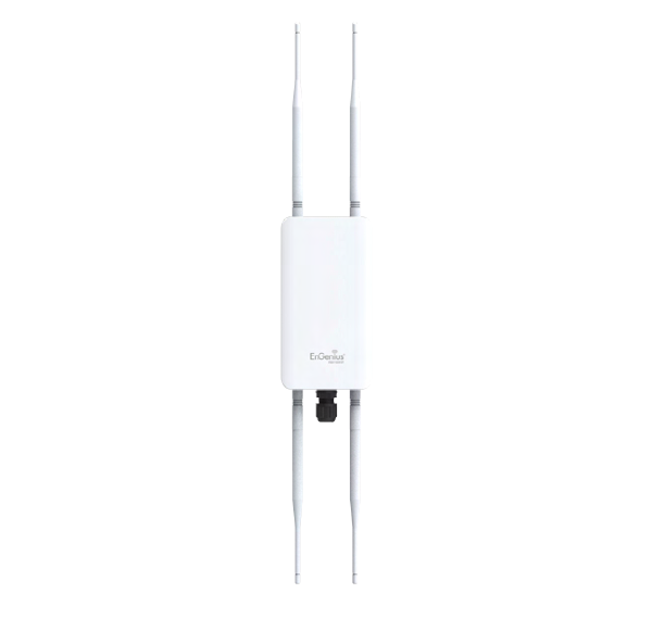
Key Features-ENH1750EXT
• Up to 29 dBm transmit power enabling long range connectivity
• Supports IEEE802.11ac/a/b/g/n wireless standards with up to
450 Mbps data rate on 2.4GHz band and 1300Mbps on 5GHz
band
• Three detachable 5 dBi 2.4 GHz Omni-directional antennas
• Three detachable 7 dBi 5 GHz Omni-directional antennas
• Can be monitored after deployment with EnGenius EZ
ControllerTM software for Windows (Free online download)
• Mesh Supported
• Can be used with included power adapter or via PoE with PoE
802.3at - capable switches or injectors
• Dual Band/Three Stream
• Band Steering shifts dual band clients to 5 GHz for better
throughput performance
• Secured Guest Network option available
Introduction
The ENH1750EXT is a high-powered, long-range 3x3 Dual-
Band Wireless 802.11 ac/a/b/g/n Outdoor Access Point
with speeds up to 450 Mbps on 2.4GHz and 1300Mbps on
5GHz band. It can be congure as an: Access Point, Client
Bridge, or WDS (AP, Station & Bridge). The ENH1750EXT is
designed to operate in a variety of outdoor environments.
Its high-powered, long-range characteristics make it a cost-
Introduction
effective alternative to ordinary Access Points that don’t
have the range and reach to connect to a growing number of
wireless users who wish to connect to a business network.
The ENH1750EXT supports the 2.4GHz frequency band
under 802.11 b/g/n mode while at the same time providing
5GHz band under 802.11 ac/a/n mode for communicating
6
to and from 5GHz capable computers, tablets or smart
phones or transferring les. Several ENH1750EXTs can
be deployed in a campus setting using the 5GHz band as
a backhaul to provide multiple 2.4GHz wireless cells for
computers or mobile devices in common outdoor areas.
The ENH1750EXT is easy to install in virtually any location
with its included PoE (Power over Ethernet) injector for
quick outdoor installation. The ENH1750EXT enables
network administrators to control its transmit power
and feature settings for selecting narrow bandwidth and
trafc shaping. The ENH1750EXT also supports wireless
encryption including Wi-Fi Protected Access (WPA-PSK/
WPA2-PSK) Encryption, and IEEE 802.1x with RADIUS.
System Requirements
The following are the Minimum System Requirements in
order to congure the device.
• Computer with an Ethernet interface or wireless network capability
• Windows OS (XP, Vista, 7), Mac OS, or Linux-based operating systems
• Web-Browsing Application (i.e.: Internet Explorer, Firefox, Safari, or
another similar browser application)
7
Package Contents
The ENH1750EXT package contains the following items:*
• ENH1750EXT Access Point
• 3 detachable 5 dBi 2.4 GHz Omni-directional Antenna
• 3 detachable 7 dBi 5 GHz Omni-directional Antenna
• Power Adapter (48V/0.8A)
• PoE Injector (EPE-48GR)
• Grounding Cable
• Pole Mount Bracket
• Wall Mount Base
• Mounting Screw Set
• Quick Installation Guide
• Technical Support Card
*(all items must be in package to issue a refund):
8
Maximum data rates are based on IEEE 802.11 standards. Actual throughput and range may vary depending on many factors including environmental conditions, distance between
devices, radio interference in the operating environment, and mix of devices in the network. Features and specications subject to change without notice. Trademarks and registered
trademarks are the property of their respective owners. For United States of America: Copyright © 2014 EnGenius Technologies, Inc. All rights reserved.
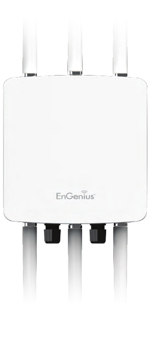
Key Features-ENH1350EXT
• Up to 28 dBm transmit power enabling long range connectivity
• Supports IEEE802.11ac/a/b/g/n wireless standards with up to
450 Mbps data rate on 2.4GHz band and 1300Mbps on 5GHz band
• Two detachable 5.17 dBi 2.4 GHz Omni-directional antennas
• Two detachable 5.17 dBi 5 GHz Omni-directional antennas
• Can be monitored after deployment with EnGenius EZ
ControllerTM software for Windows (Free online download)
• Can be used with included power adapter or via PoE with
Proprietary 54V.
• Fast Transition and Handover between Access Points
• Band Steering shifts client devices to a proper frequency band
for getting more bandwidth and speed under an Access Point.
• Secured Guest Network option available
Introduction
ENH1350EXT equips with two powerful RF interfaces that
support up to 867 Mbps in 5GHz frequency band and 400
Mbps in 2.4GHz frequency band (with 2ss/VHT40 clients).
It can be congured as an: Access Point, Client Bridge, or
WDS (AP, Station & Bridge). The ENH1350EXT is designed
to withstand harsh environment conditions including
serve and prolonged exposure to sunlight, extreme cold,
frost, snow, rainfall, hail and humidity. The ENH1350EXT
supports the 2.4GHz frequency band under 802.11 b/g/n
Introduction
mode while at the same time providing 5GHz band under
802.11 ac/a/n mode for communicating to and from 5GHz
capable computers, tablets or smart phones or transferring
les. Several ENH1350EXTs can be deployed in a campus
setting using the 5GHz band as a backhaul to provide
multiple 2.4GHz wireless cells for computers or mobile
9
devices in common outdoor areas.
The ENH1350EXT is easy to install in virtually any location
with its included PoE (Power over Ethernet) adapter for
quick outdoor installation. The ENH1350EXT enables
network administrators to control its transmit power
and feature settings for selecting narrow bandwidth and
trafc shaping. The ENH1350EXT also supports wireless
encryption including Wi-Fi Protected Access (WPA2-PSK)
Encryption, and IEEE 802.1x with RADIUS.
System Requirements
The following are the Minimum System Requirements in
order to congure the device.
• Computer with an Ethernet interface or wireless network capability
• Windows OS(XP, Vista, 7, 8, 10), Mac OS, or Linux-based operating
systems
• Web-Browsing Application (i.e.: Internet Explorer, Firefox, Safari, or
another similar browser application)
Package Contents
The ENH1350EXT package contains the following items:*
• ENH1350EXT Access Point
• 2 detachable 5 dBi 2.4 GHz Omni-directional Antenna
• 2 detachable 5 dBi 5 GHz Omni-directional Antenna
• PoE Adapter (54V/0.6A)
• Power Cord
• Pole Mount Strap
• Wall Mount Screw set
• Quick Installation Guide
*(all items must be in package to issue a refund)
10
WDS Detail
WDS AP
WDS Bridge
WDS Station
Mesh Detail
Mesh AP
Mesh Only
Management
Auto Channel Selection
Multiple SSID: 16 SSIDs, 8 SSIDs per Radio
BSSID
SNMP V1/V2c/V3
MIB I/II, Private MIB
VLAN Tag/VLAN Pass-through
Clients Statistics
Save Conguration as User Default
Fast Roaming
E-Mail Alert
RADIUS Accounting
Guest Network
Control
CLI Supported
Distance Control (Ack Timeout)
802.1X Supplicant (CB Mode)
Multicast Supported
Auto Reboot
Obey Regulatory Power
Standard:
IEEE802.11ac/a/n on 5 GHz
IEEE802.11b/g/n on 2.4 GHz
IEEE802.3at
Antenna
6 External N-type Antenna
3 x detachable 5 dBi 2.4 GHz Omni-directional Antennas
3 x detachable 7 dBi 5 GHz Omni-directional Antennas
Physical Interface
2 x 10/100/1000 Gigabit Ethernet Port with PoE support
LAN1 Port: IEEE802.3at PoE Input
LAN2 Port: IEEE802.3af PoE Output
Both Ethernet Ports support Surge Protection to 6KV
LED Indicator
Power
LAN 1
LAN 2
2.4 GHz
5 GHz
Power Requirements
External Power Adapter, DC IN, 48V/0.8A
IEEE802.3at support
Operation Modes
Access Point
WDS
Mesh
Technical Specications
ENH1750EXT
11
Security
WEP Encryption - 64/128/152 bit
WPA/WPA2 Personal (WPA-PSK using TKIP or AES)
WPA/WPA2 Enterprise (WPA-PSK using TKIP or AES)
Hides SSID in beacons
MAC address ltering, up to 50 MACs
Wireless STA (Client) connection list
Https Support
SSH Support
QoS (Quality of Service)
Complaint with IEEE 802.11e standard
Physical/Environment Conditions
Operating:
Temperature: -4 °F to 158 °F (-20 °C to 70 °C)
Humidity (non-condensing): 90% or less
Storage:
Temperature: -22 °F to 176 °F (-30 °C to 80 °C)
Humidity (non-condensing): 90% or less
12
Management
Auto Channel Selection
Multiple SSID: 8 SSIDs per Radio
BSSID
SNMP V1/V2c/V3
MIB I/II, Private MIB
VLAN Tag/VLAN Pass-through
Clients Statistics
Save Conguration as User Default
Fast Roaming
E-Mail Alert
RADIUS Accounting
Guest Network
Control
CLI Supported
Distance Control (Ack Timeout)
802.1X Supplicant (CB Mode)
Multicast Supported
Auto Reboot
Obey Regulatory Power
Security
WPA2 Personal
WPA2 Enterprise
Hides SSID in beacons
MAC address ltering, up to 32 MACs
Wireless STA (Client) connection list
Https Support
SSH Support
Standard:
IEEE802.11ac/a/n on 5 GHz
IEEE802.11b/g/n on 2.4 GHz
IEEE802.3at
Antenna
4 External N-type Antenna
2 x detachable 5.17 dBi 2.4 GHz Omni-directional Antennas
2 x detachable 5.17 dBi 5 GHz Omni-directional Antennas
Physical Interface
1 x 10/100/1000 Gigabit Ethernet Port with PoE support
LAN Port: IEEE802.3af and Proprietary 54V POE input.
Ethernet Ports support Surge Protection to 1KV
LED Indicator
Power
LAN
2.4 GHz
5 GHz
Power Requirements
External Power Adapter, DC IN, 48V/0.6A
Operation Modes
Access Point
Client Bridge
WDS
WDS Detail
WDS AP
WDS Bridge
WDS Station
ENH1350EXT
13
QoS (Quality of Service)
Complaint with IEEE 802.11e standard
Physical/Environment Conditions
Operating:
Temperature: -4 °F to 140 °F (-20 °C to 60 °C)
Humidity (non-condensing): 0%~90% typical
Storage:
Temperature: -40 °F to 176 °F (-40 °C to 80 °C)
Humidity (non-condensing): 0%~90% typical
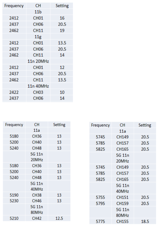
Power Setting
ENH1350EXT follow below power table to do power setting.
2.4G BAND1
5G BAND1 5G BAND 4
14
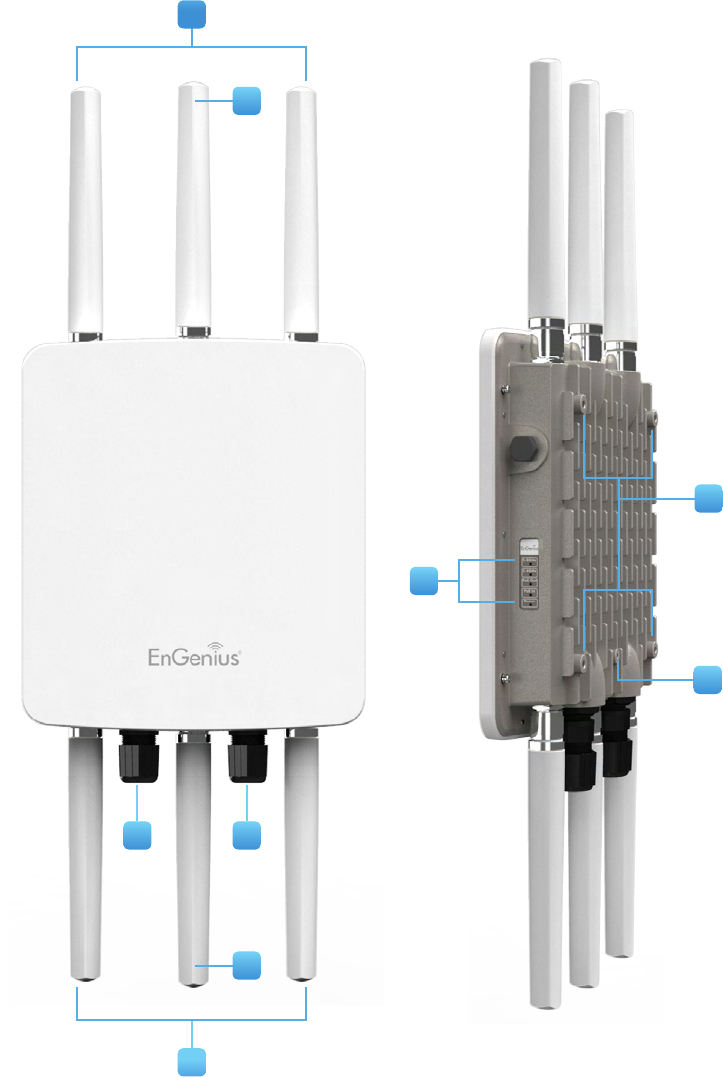
Physical Interface(ENH1750EXT)
Dimensions and Weights
Length: 11.22”
Width: 8.58”
Depth: 2.1”
Weight: 4.17 lbs
1 2.4 GHz Antennas: Detachable 5 dBi 2.4 GHz Omni-directional
2 5 GHz Antennas Detachable 7 dBi 5 GHz Omni-directional
3 LAN Port 1 (802.3at PoE Input): Ethernet port for RJ-45 cable.
4 LAN Port 2 (802.3af PSE Output): Ethernet port for RJ-45 cable.
5 LED Indicators: LED lights for Power, LAN Port 1, LAN Port 2,
2.4 GHz Connection and 5 GHz Connection.
6 Ground
7 Mounting Holes: Using the provided hardware, the ENH1750EXT
can be attached to a wall or pole.
1
6
7
1
2
2
3 4
5
15
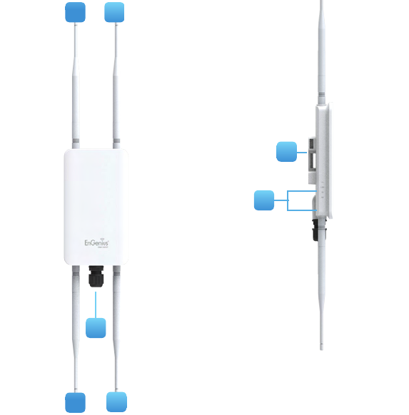
Physical Interface(ENH1350EXT)
Dimensions and Weights
Length: 6.83”
Width: 4.38”
Depth: 1.19”
Weight: TBD
1 2.4 GHz Antennas: Detachable 5.17 dBi 2.4 GHz Omni-directional
2 5 GHz Antennas Detachable 5.17 dBi 5 GHz Omni-directional
3 LAN Port (802.3af and Proprietary 54V PoE Input): Ethernet
port for RJ-45 cable.
4 LED Indicators: LED lights for Power, LAN Port, 2.4 GHz
Connection and 5 GHz Connection.
5 Mounting Holes: Using the provided hardware, the ENH1350EXT
can be attached to a wall or pole.
1
5
2
3
4
2
1

16
Chapter 2
Before You Begin
17
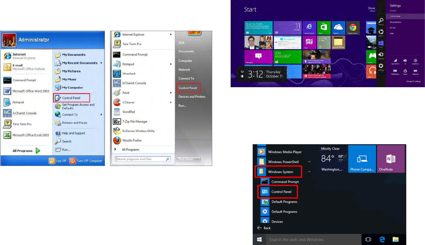
Windows XP/Windows 7/Windows 8/Windows
10
In order to use the Access Point, you must rst congure the
TCP/IPv4 connection of your Windows OS computer system.
1a. Click the Start button and open the Control Panel
1b. Move your mouse to the lower right hot corner to
display the Charms Bar and select the Control Panel in
Windows 8 OS.
1c. In Windows 10, click Start to select All APPs to enter
the folder of Windows system for selecting Control
Panel.
Computer Settings
Windows XP Windows 7
Windows 8
Windows 10
18
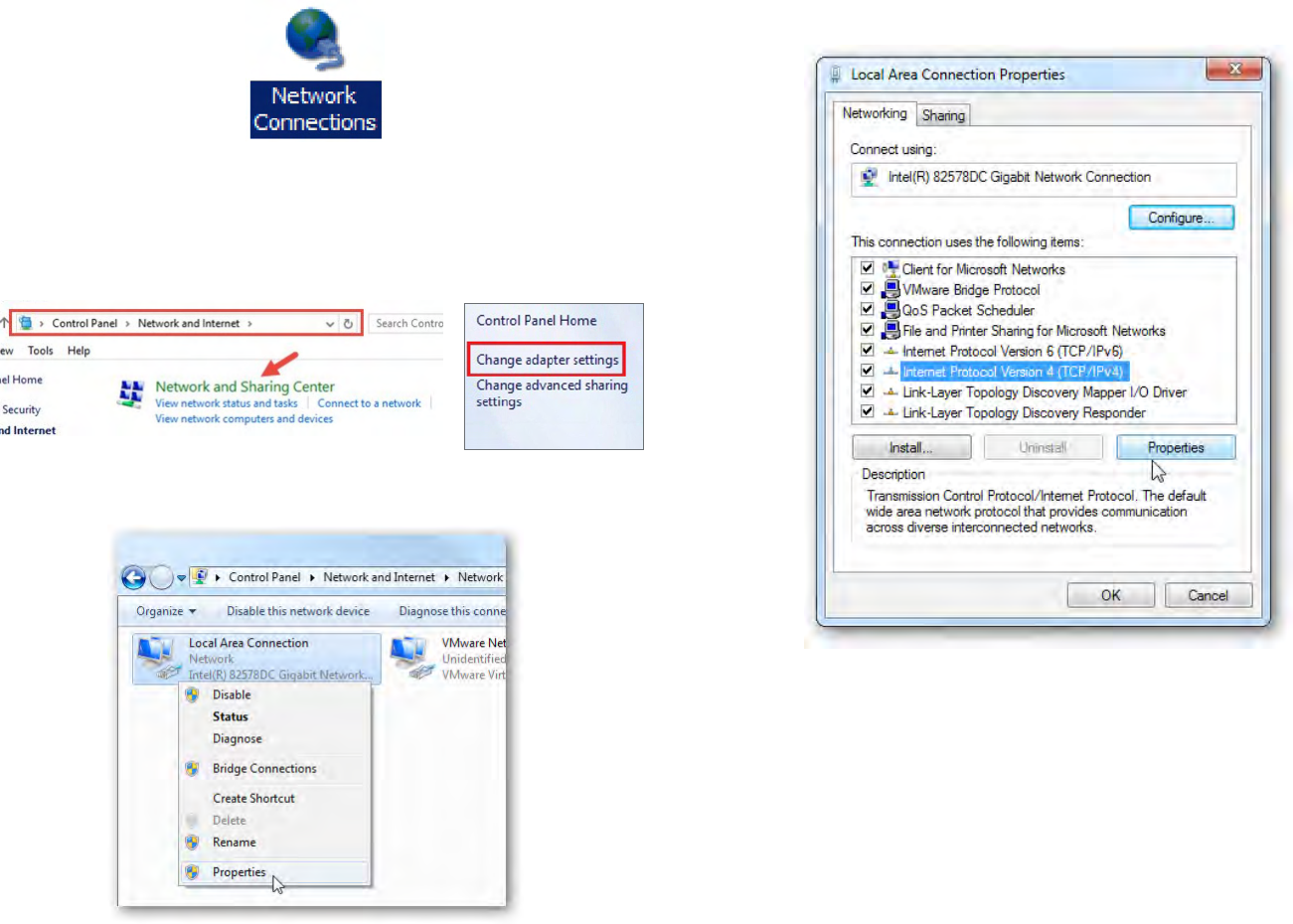
2a. In Windows XP, click Network Connections.
2b. In Windows 7/Windows 8/Windows 10, click View
Network Status and Tasks in the Network and
Internet section, then select Change adapter settings.
3. Right click on Local Area Connection and select Properties.
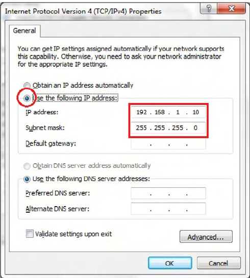
4. Select Internet Protocol Version 4 (TCP/IPv4) and then
select Properties.
5. Select Use the following IP address and enter an IP
address that is different from the Access Point and Subnet
mask, then click OK.
19
Note: Ensure that the IP address and Subnet mask are
on the same subnet as the device.
For example: ENH220EXT IP address: 192.168.1.1
PC IP address: 192.168.1.2 – 192.168.1.255
PC Subnet mask: 255.255.255.0

20
Apple Mac OS X
1. Go to System Preferences (Which can be opened in the
Applications folder or selecting it in the Apple Menu).
2. Select Network in the Internet & Network section.
3. Highlight Ethernet.
4. In Congure IPv4, select Manually.
5. Enter an IP address that is different from the Access
Point and Subnet mask then press OK.
Note: Ensure that the IP address and Subnet mask are
on the same subnet as the device.
For example: ENH900EXT IP address: 192.168.1.1
PC IP address: 192.168.1.2 – 192.168.1.255
PC Subnet mask: 255.255.255.0
6. Click Apply when done.
21
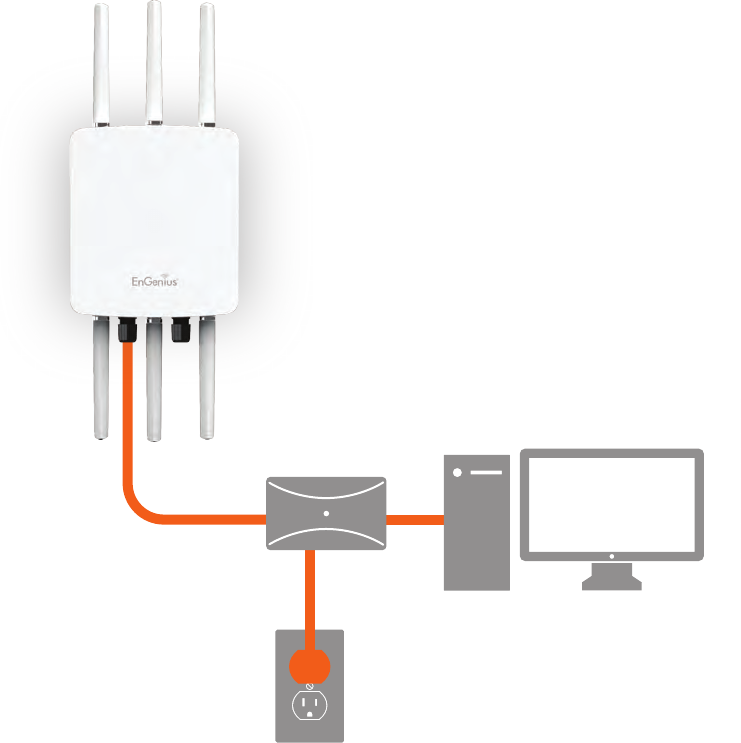
1. Connect one end of the Ethernet cable into the main
LAN port (PoE) of the Access Point and the other end to
the AP Ethernet port on the PoE injector.
2. Connect the Power Adapter to the DC-IN port of the
PoE injector and plug the other end in to an electrical
outlet.
3. Connect the second Ethernet cable into the LAN port of
the PoE injector and the other end to the Ethernet port
on the computer.
4. Screw on the provided antennas to the device. Once
both connections are secure, verify the following:
a) Ensure that the POWER light is on (it will be green).
b) Ensure that the 2.4 GHz/5 GHz WLAN light is on (it will
be green for both 5 GHz and 2.4 GHz).
c) Ensure that the LAN (Computer/ENH1750EXT
Connection) light is on (it will be green).
d) Once all three lights are on, proceed to set up the
Access Point using the computer.
This diagram depicts the hardware conguration.
Note: The Access Point supports both IEEE 802.3at PoE
(Power over Ethernet) or the included power injector.
You may use either one as the power source. Do NOT
use both at the same time.
Hardware Installation
ENH1750EXT
Ethernet
PC
Power
Outlet
PoE Injector/
PoE Swtich
22
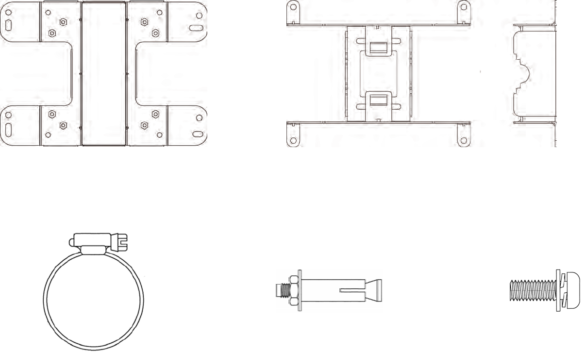
Mounting the ENH1750EXT
Using the provided hardware, the ENH1750EXT can be attached to a wall or a pole.
1. Wall Mount Kit 260x180x7 (mm) 2. Pole Mount Kit 140x112x33 (mm)
3. Pipe 63.5 (D) x 12.7 (mm) 4. Tool 20(D) x 6 (mm) 5. Screws: 6.5(D) x 9.95 (mm)
23
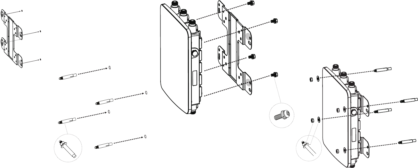
To attach the ENH1750EXT to a wall using wall
mounting kit.
1. Mark the four locations of the mounting holes on the
at mounting surface.
2. Drill a 37 mm deep 8 mm hole in the markings and
hammer the bolts into the openings.
3. Place the lock and at washers on the four hex cap screws
and drive the screws to attach the bracket to the back of
the Access Point.
4. Tighten the at washers to secure the bracket to the
mounting surface.
2.
3.
4.
1.
24
To attach the ENH1750EXT to a pole using the
provided pole mounting kit:
1. Place the lock and at washers on the four hex cap screws
and drive the screws to attach the bracket to the back of
the Access Point.
2. Drive the four round head screws to attach the Pole
Mount Bracket to the bracket.
3. Thread the open end of the Pole Strap through the two
tabs on the Pole Mount Bracket .
4. Lock and tighten the Pole Strap to secure the Pole Mount
Bracket to the pole.
Note: See diagram below for vertical and horizonal
placements.
1. 3.2.
horizontal placement horizontal placement horizontal
placement
4.
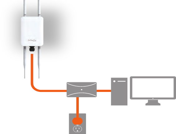
25
1. Connect one end of the Ethernet cable into the LAN port
(PoE) of the AP/ Bridge and the other end to the PoE
port on the PoE adapter.
2. Connect the Power cord with the PoE Adapter and plug
the other end into an electrical outlet.
3. Connect the second Ethernet cable into the LAN port of
the PoE adapter and the other end to the Ethernet port
on the computer.
4. Screw on the provided antennas to the top of this device.
Note: The AP/Bridge should ONLY be powered via
Ethernet cable connected to the included PoE Adapter.
This diagram depicts the hardware conguration.
Note: The AP/Bridge should ONLY be powered via
Ethernet cable connected to the included PoE Adapter.
Hardware Installation
ENH1350EXT
Ethernet
PC
Power
Outlet
PoE Adapter
26
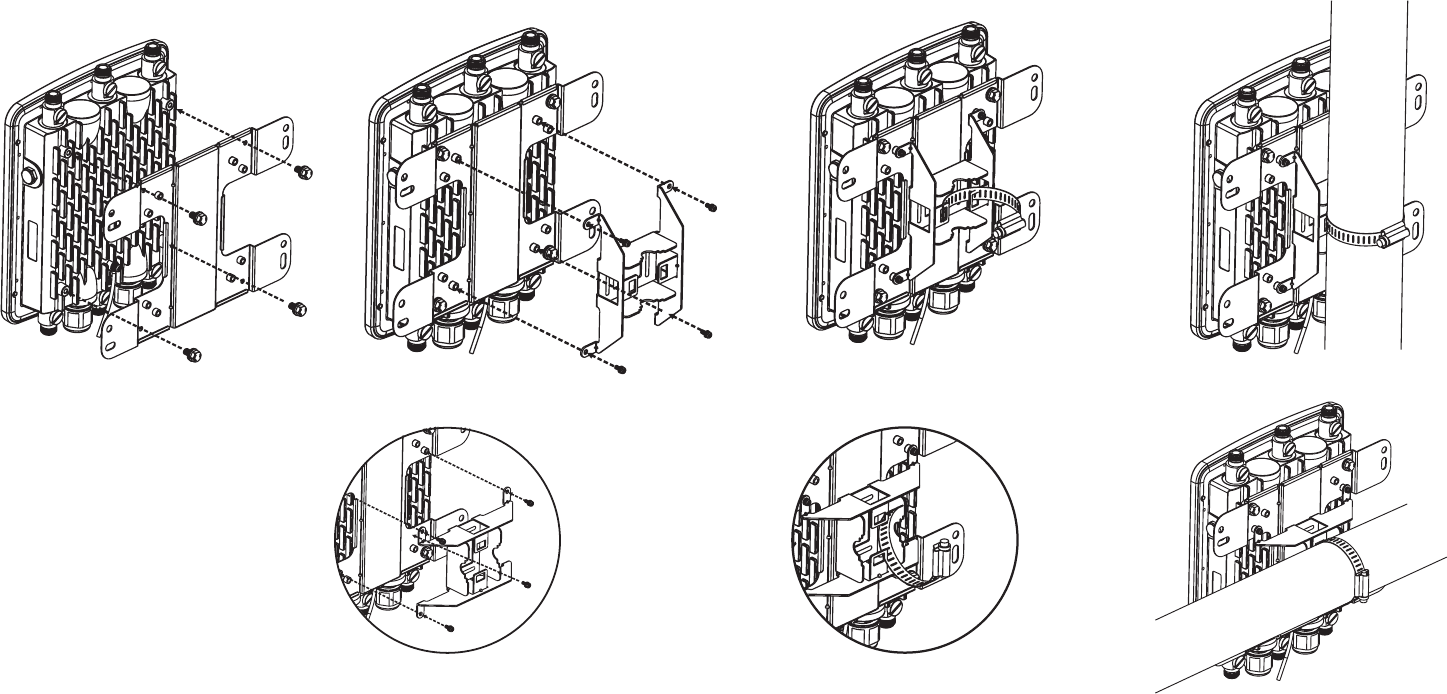
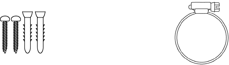
Mounting the ENH1350EXT
Using the provided hardware, the ENH1350EXT can be attached to a wall or a pole. The height should not exceed 2 meter.
1. Wall Mounting Kit
(Anchors: Φ5.5*18 mm & Bolts: Φ8*25mm)
2. Pole Mounting Strap
(Φ66*12.6 mm)
Anchors Bolts
27
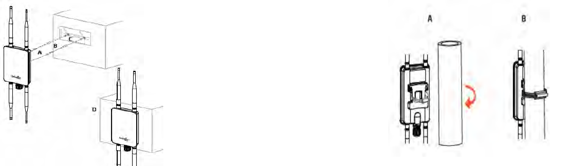
To attach the ENH1350EXT to a wall using wall
mounting kit.
A. Determine where the Access Point to be placed and
stick the Adhesive label on the surface.
B. Use the appropriate drill bit to drill two 8.1mm
diagram and 26mm depth holes on the markings of the
label.C. Remove the label and screw the anchors unto
the holes until they are ush with the wall.
D. Screw the included screws into the anchors. Place the
Access Point against wall with the mounting screw heads.
To attach the ENH1350EXT to a pole using the
provided pole mounting kit:
A. Thread the open end of the Pole Strap through the two
tabs on the Pole Mount Bracket.
B.Lock and tighten Pole Strap to secure Pole Mount Bracket
to the pole.

28
Chapter 3
Conguring Your
Access Point
29
This section will show you how to congure the device
using the web-based conguration interface.
Default Settings
Please use your Ethernet port or wireless network adapter
to connect the Access Point.
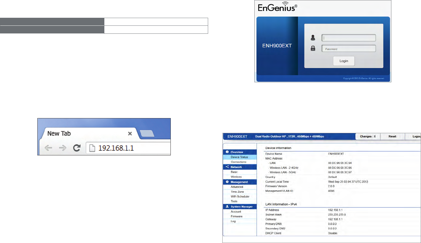
IP Address 192.168.1.1
Username / Password admin / admin
Web Conguration
1. Open a web browser (Internet Explorer/Firefox/Safari/
Chrome) and enter the IP Address http://192.168.1.1
Note: If you have changed the default LAN IP Address of
the Access Point, ensure you enter the correct IP Address.
2. The default username and password are admin.
Once you have entered the correct username and
password, click the Login button to open the web-base
conguration page.
*The model name will be varied by different models.
3. If successful, you will be logged in and see the User
Menu of this Access Point.
Conguring Your Access Point

30
Chapter 4
Building a Wireless
Network
31
Before starting to congure this Access Point, you may realize the used scenario under varied operating modes.The AP
has the ability to operate in various modes. This chapter describes purpose of different operating modes and lists down
the operating modes for outdoor Access Points.
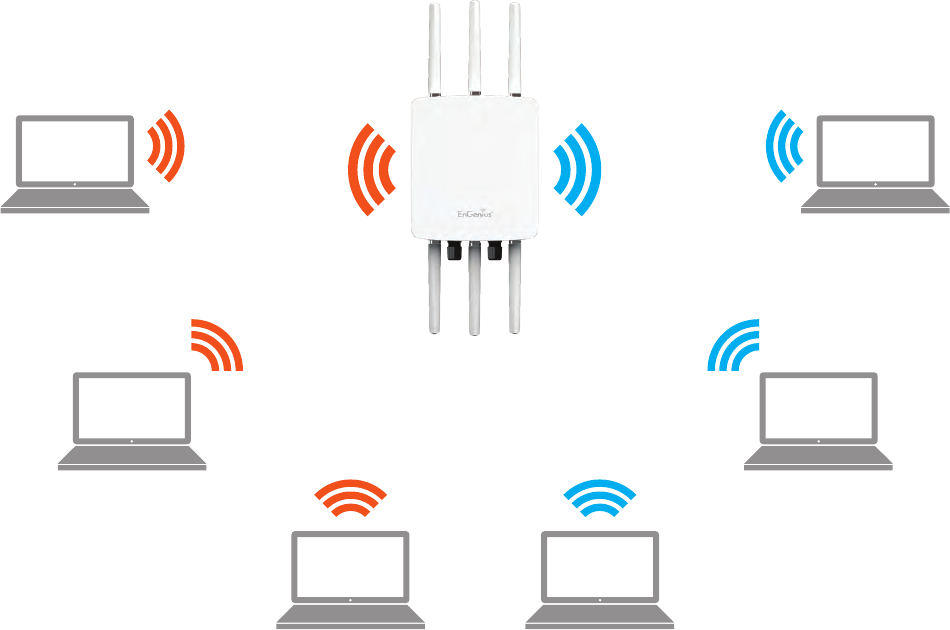
Access Point Mode
In Access Point Mode, AP behaves likes a central connection for stations or clients that support IEEE 802.11ac/a/b/g/n networks.
The stations and clients must be congured to use the same SSID (Service Set Identier) and security password to associate
with the AP. The AP supports up to eight SSIDs at the same time for secure access.
AP
Access Point
Client
Client Client
Client Client
Client
2.4 GHz 5 GHz
32
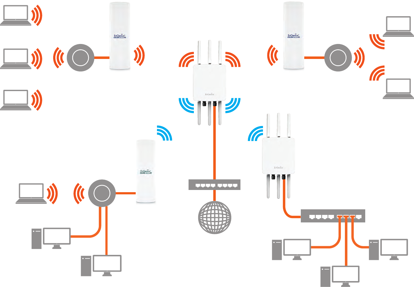
Client Bridge Mode
The AP can be used as a centralized Outdoor Access Point with which other EnGenius Wireless N 2.4 or 5 GHz Outdoor
Client Bridges can associate; leveraging the long-range capability of their internal high-gain directional antennas, resulting
in a very cost-effective solution to expand a company network over a multiple building campus.
AP
Access Point
AP
Client Bridge
ENH202
Client Bridge
ENH202
Client Bridge
ENH500
Client Bridge
Client
Client
Client
Client
Client
Client
Client
Client
Client
Client
Client
2.4 GHz
5 GHz 5 GHz
2.4 GHz
Switch
Switch
Internet
33
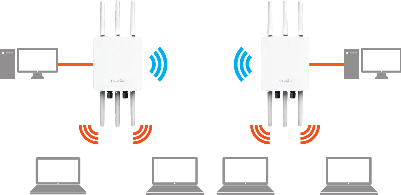
WDS AP Mode
The AP also supports WDS AP mode. This operating mode allows wireless stations to connect with Access Point via using
WDS technology. In this mode, congure the MAC addresses or SSIDs in both Access Points to enlarge the wireless area
by enabling WDS Link settings. WDS supports up to four (4) AP MAC addresses and four (4) SSIDs at the same time.
AP
WDS AP-
AP
WDS AP-
2.4 GHz 2.4 GHz
5 GHz 5 GHz
Client Client Client Client
Client
Computer
Client
Computer
34
WDS Bridge Mode
In WDS Bridge Mode, the Accesss Point can wirelessly connect different LANs by conguring the MAC address and security
settings of each Access Points. Use this operating mode when two wired LANs located a small distance apart want to
communicate with each other. The best solution is to use the Access Point to wirelessly connect two wired LANs, as
shown in the following diagram.
WDS Bridge Mode can establish up to four (4) to eight (8) WDS links, creating a star-like network.
Note: WDS Bridge Mode does not act as an Access Point. Access Points linked by WDS are using the same frequency
channel. More Access Points connected together may lower throughput. This conguration can be susceptible to
generate endless network loops in your network, so it is recommended to enable the Spanning Tree function to
prevent this from happening.
AP
WDS Bridge
AP
WDS Bridge-
AP
WDS Bridge-
Client
Computer
Client
Computer
Client
Computer
35
WDS Station Mode
WDS station (WDS STA) mode expands the WDS by receiving a wireless signal/service and sharing it through the Ethernet
port. With WDS STA mode.
Access Point
WDS AP
on both 5 GHz or 2.4 GHz
Access Point
WDS Station
Access Point
WDS Station
Access Point
WDS Station
36
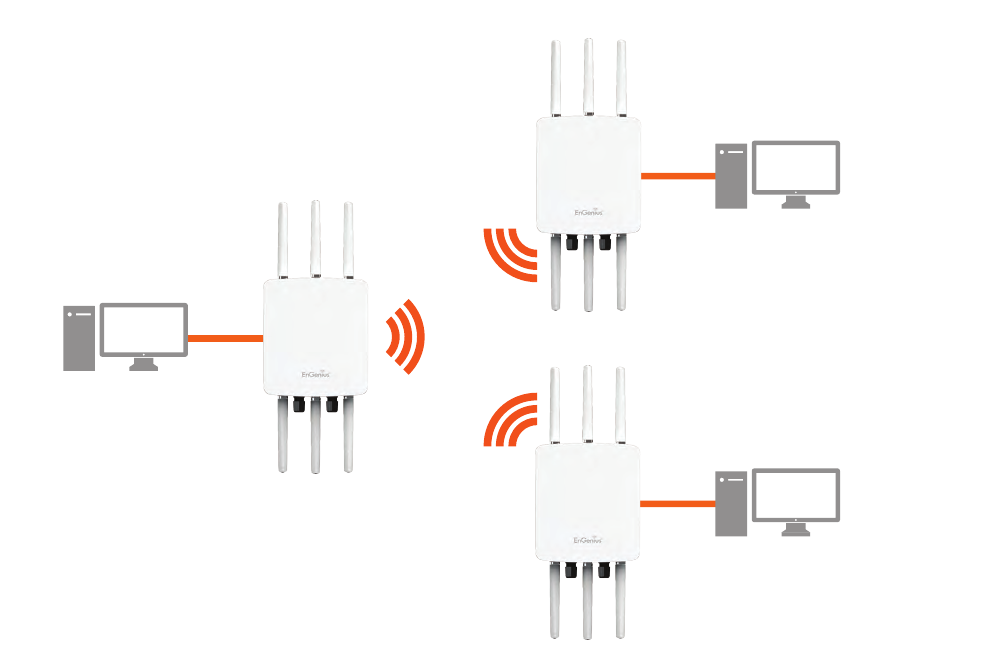
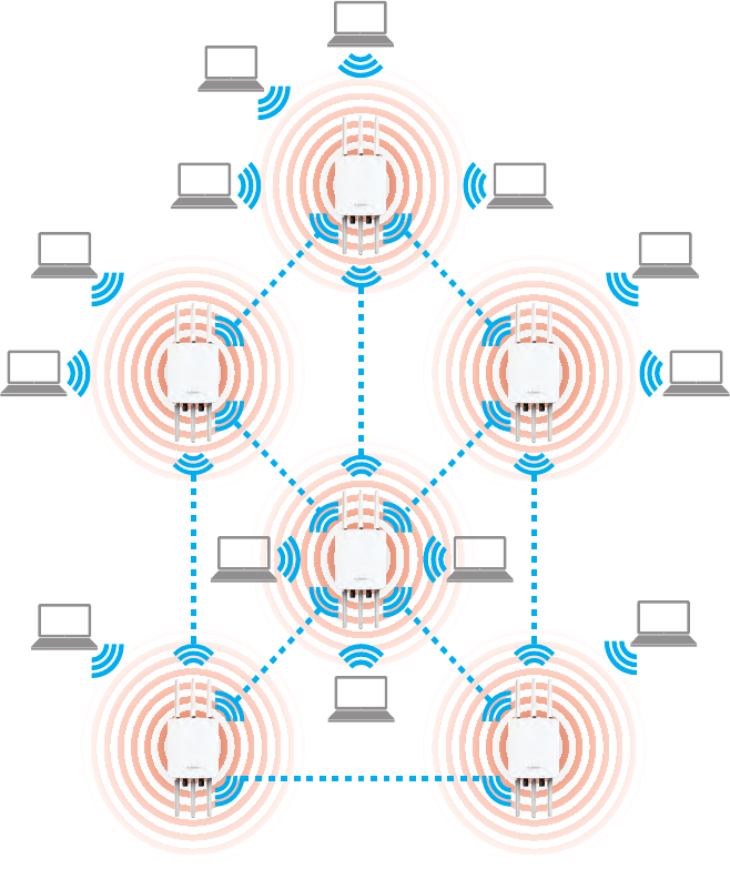
AP Mesh Mode-ENH1750EXT
Under the AP Mesh mode, the ENH1750EXT can be used as the central connection hub for station or clients that
support IEEE 802.11 b/g/n network. Under this mode, the ENH1750EXT can be congured with the same Mesh SSID
and security password in order to associate with other ENH1750EXTs, as well as connect with clients under the same
SSID and encryption signatures. For example, you would use one band to connect Access Points in range with Mesh
Client Computer
Client Computer
Client Computer
Client Computer
Client Computer
Client Computer
Client Computer
Client Computer
Client Computer
Client Computer
Client Computer
Client Computer
Client Computer
ENH1750EXT
Access Point
ENH1750EXT
Access Point
ENH1750EXT
Access Point
ENH1750EXT
Access Point
ENH1750EXT
Access Point
ENH1750EXT
Access Point
37
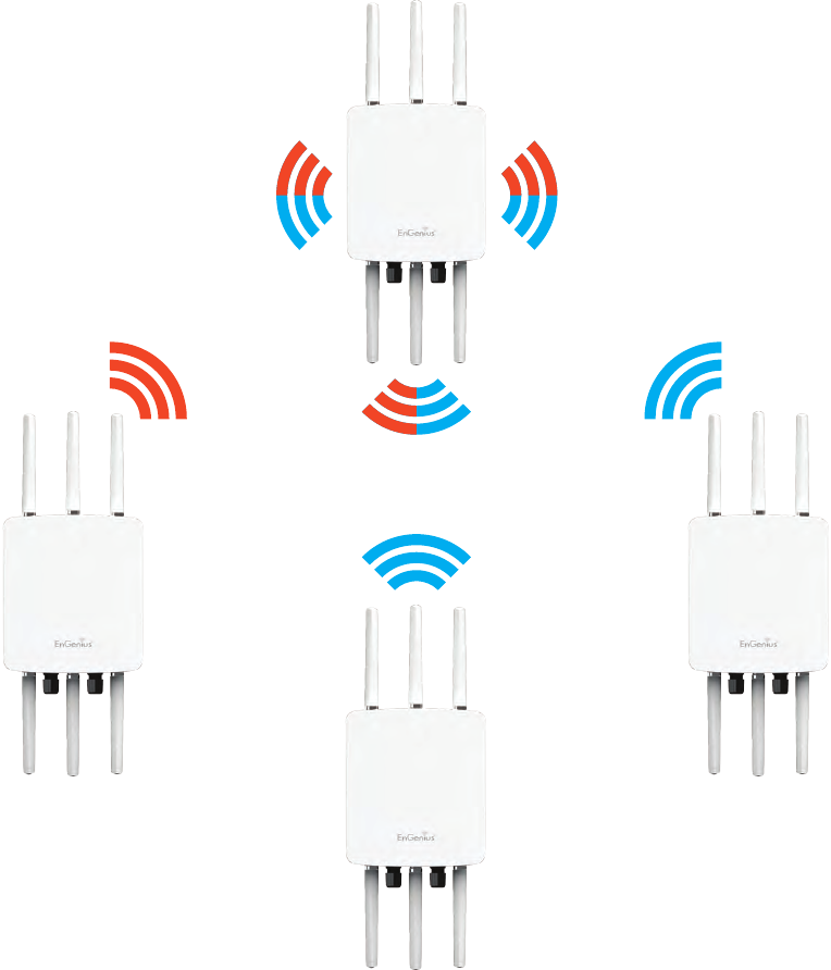
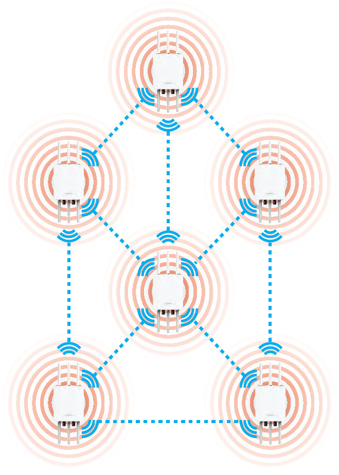
Under the Mesh-only mode, the ENH1750EXT can
be congured with the same Mesh SSID and security
password in order to associate with other Mesh enabled
ENH1750EXTs, instead of connecting with clients.
Mesh Only Mode-ENH1750EXT
ENH1750EXT
Access Point
ENH1750EXT
Access Point
ENH1750EXT
Access Point
ENH1750EXT
Access Point
ENH1750EXT
Access Point
ENH1750EXT
Access Point

38
Chapter 5
Status
39
Save Changes
This page lets you save and apply the settings shown under
Unsaved changes list, or Revert the unsaved changes and
revert to the previous settings that were in effect.
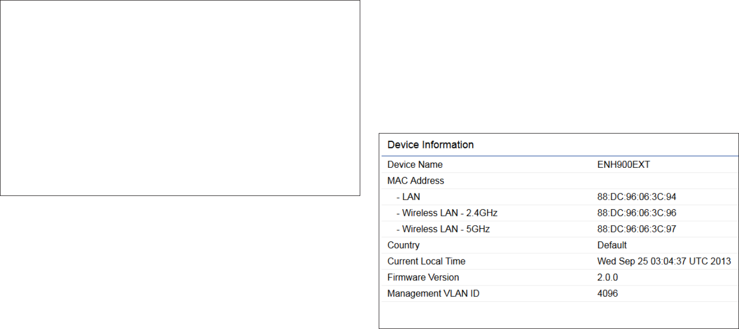
Device Status
Clicking the Device Status link under the Overview menu
shows the status information about the current operating
mode.
• The Device Information section shows general system
information such as Device Name, MAC Address, Current
Time, Firmware Version, and Management VLAN ID
Note: VLAN ID is only applicable in Access Point, WDS
AP or WDS BR mode.
• The Memory Information section shows usage of
Overview
40
memory such as Total Available, Free, Cached, Buffered
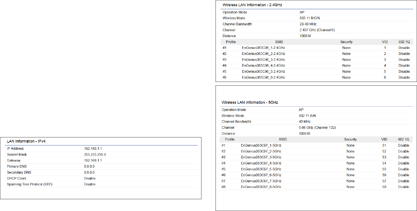
• The LAN Information section shows the Local Area
Network settings such as the LAN IP Address, Subnet
mask, Primary DNS Address, Secondary DNS Address,
status of DHCP client, and status of Spanning Tree
protocol (STP).
• The Wireless LAN Information 2.4 GHz/5 GHz section
shows wireless information such as Operating Mode,
Frequency, and Channel. Since this Access Point
supports multiple-SSIDs, information about each SSID,
the ESSID, and security settings, are displayed
Note: Prole Settings are only applicable in Access Point
and WDS AP modes.
• The Statistics section shows Mac information such as
SSID, MAC address, RX and TX.
41
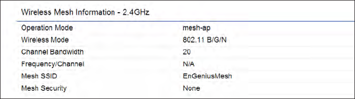
• The Wireless Mesh Information - 2.4 GHz section
shows wireless information such as Operation Mode,
Wireless Mode, Channel Bandwidth, Frequency/
Channel, Mesh SSID and Mesh Security.
42
2.4 GHz/5 GHz Connection List
Click the connection link under the Overview menu
displays the connection list of clients associated to the
ENH1750EXT’s 2.4 GHz/5 GHz, along with the MAC
addresses and signal strength for each client. Clicking
Refresh updates the client list.
Note: Only applicable in Access Point and WDS AP
modes.
2.4 GHz/5 GHz WDS Link List
Click the connection link under the Overview menu. This
page displays the current status of the WDS link, including
WDS Link ID, MAC Address, Link Status and RSSI.
Note: Only applicable in WDS AP and WDS Bridge modes.
Realtime
The Realtime section contains the following options:
CPU Loading: 3 minutes CPU loading percentage
information, it displays current loading, average loading
and peak loading status. Left bar is loading percentage;
button is time tracing. Interval is every 3 seconds
Connection Realtime
43
Trafc Loading: 2.4GHz and 5GHz and Ethernet port
inbound and outbound trafc by current, average and
peak time.
Realtime Connection (Pkts): Overview on current
active network connections. It displays UDP and TCP
packets information and other connection status. UDP
connections curve is in blue; TCP connection curve is
in green; others curve is in red. Below of chart shows
connections source and destination.
The Mesh Link List
Monitor the 2.4GHz Mesh Link List under the status menu.
The page will display the current status of the Mesh Links
under the Mesh AP mode and Mesh nodes under the Mesh
Only mode.
Note: Only Applicable in the Mesh AP and Mesh Only
mode.

44
Chapter 6
Network
45
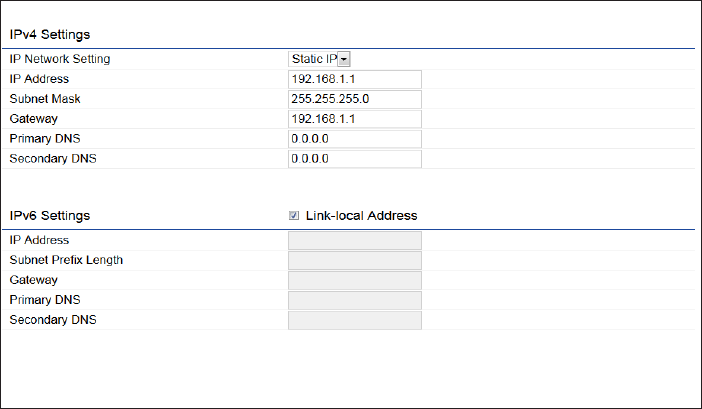
IPv4/IPv6 Settings
This page allows you to modify the device’s IP settings. IP Network Settings: Select whether the device IP address
will use a static IP address specied in the IP address eld
or be obtained automatically when the device connects to
a DHCP server.
IP Address: The IP address of this device.
Subnet Mask: The IP Subnet mask of this device.
Gateway: The Default Gateway of this device. Leave it
blank if you are unsure of this setting.
Primary/Secondary DNS: The primary/secondary DNS
address for this device.
Save: Click Save to conrm the changes.
Basic IP Settings
46
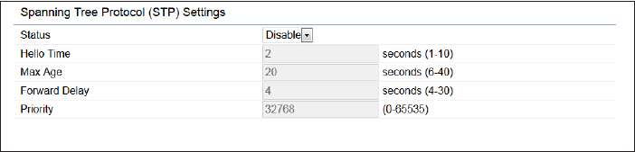
Spanning Tree Protocol (STP) Settings
This page allows you to modify the Spanning Tree settings.
Enabling the Spanning Tree protocol will prevent network
loops in your LAN network.
Spanning Tree Status: Enables or disables the Spanning
Tree function.Default is Disable.
Hello Time: Species Bridge Hello Time in seconds. This
value determines how often the device sends handshake
packets to communicate information about the topology
throughout the entire Bridged Local Area Network.
Max Age: Species Bridge Max Age in seconds. If another
bridge in the spanning tree does not send a hello packet for
a long period of time, it is assumed to be inactive.
Forward Delay: Species Bridge Forward Delay in seconds.
Forwarding delay time is the time spent in each of the
Listening and Learning states before the Forwarding state
is entered. This delay is provided so that when a new bridge
comes onto a busy network, it analyzes data trafc before
participating in the network.
Priority: Species the Priority Number. A smaller number
has a greater priority than a larger number.
Save: Click Save to conrm the changes.
47
Chapter 7
2.4 GHz & 5 GHz
Wireless
48
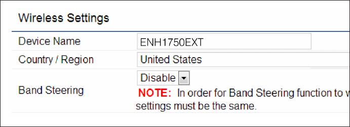
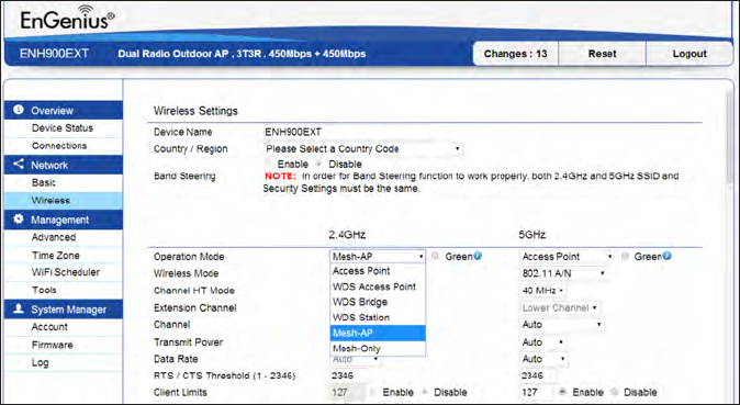
Wireless Settings
Device Name: Enter a name for the device. The name you
type appears in SNMP management. This name is not the
SSID and is not broadcast to other devices.
Band Steering: Enable Band Steering to send 802.11n
clients to the 5 GHz band, where 802.11b/g clients cannot
go, and leave 802.11b/g clients in 2.4GHz to operate at
their slower rates. Before implementing this feature, we
suggest you to assure the both 2.4GHz and 5GHz SSID,
as welll as security settings must be the same. EnGenius
Band Steering supports following advanced settings,
Force 5GHz: When band steering is congured to Force
5GHz mode, the AP will not dual band capable client
devices to network to the 2.4GHz band only if the client
devices are not currently associated on 2.4GHz radio in
this AP.
Prefer 5GHz: When band steering is congured to Prefer
5GHz mode, the AP will steer dual band capable client
devices to 5GHz radio when the RSSI value of these client
devices on 5GHz radio is more than set one. The allowed
RSSI value for default setting is -75dBm.
*Band Balance: When band steering is congured to Band
Balance mode, the AP will steer dual band capable client
devices to 5GHz when the RSSI value of these client
devices on 5GHz radio is more than set one. To evenly
allocate RF resource on the both 2.4GHz and 5GHz radios,
users also can set the portion of client devices on 5GHz
radio to assure smoothly connection. The default value of
the 5GHz radio is 75%.
Save: Click Save to conrm the changes
Wireless
49
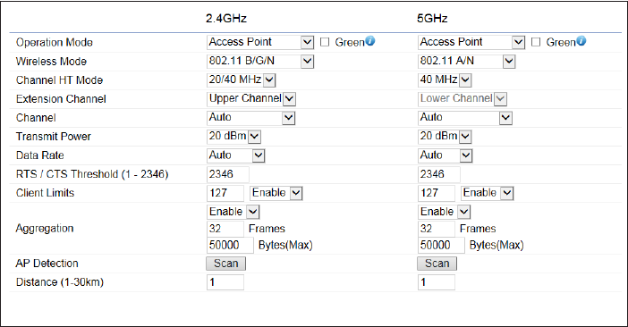
This page displays the current status of the Wireless
settings of the AP.
2.4 GHz/5 GHz Wireless Network
Operation Mode: Scrow down this list to select operation
modes for implementing on this radio. The default operation
mode is Access Point on base stations and Access Points
and is Client Bridge on Client Premise Equipements (CPE).
Meanwhile, EnGenius outdoor devices also support WDS
modes for peer to peer or peer to multi-peer connections.
Wireless Mode: Scrow down this list to select wireless
broadcasting standard on 2.4GHz and 5GHz frequency
bands.
Channel HT Mode: Scrow down this list to select bandwidth
for operating under a frequency band. The default channel
bandwidth is 20 MHz on 2.4GHz frequency radio and 40
MHz on 5GHz frequency radio. Considering the different
applications, users can decide to implement a channel
bandwidth to fulll real applications. The larger the channel,
the greater the transmission quality and speed.
Transmit Power (Tx Power): Default Tx power is Auto
to obey regulartory power of each country.
Channel: Click Configuration button to open a new
windows to configure channels for performing wireless
service.
50
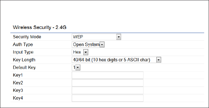
Wireless Security
The Wireless Security section lets you congure the AP’s
security modes
Secuirty Mode: Including WEP, WPA2-PSK, WPA2. We
strongly recommend you to use WPA2-PSK mode.
* Setting of WEP mode:
Auth Type: Select Open System or Shared Key.
Input Type:
ASCII: Regular Text (recommended)
Hexadecimal Numbers (For advanced users)
Key Length: Select the desired option and ensure that
wireless clients use the same setting. Your choices are 64,
128, and 152-bit password lengths.
Default Key: Select the Key you wish to be the default.
Transmitted data is ALWAYS encrypted using the Default
Key; the other Keys are for decryption only. You must enter
a Key Value for the Default Key.
Encryption Key Number: Enter the Key Value or values you
wish to use. Only the Key selected as Default is required.
The others are optional.
51
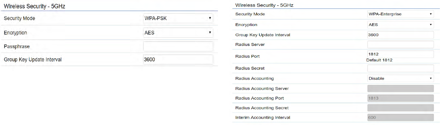
* Setting of WPA2-PSK:
Encryption: You may select AES, TKIP or Both (TKIP+AES)
to be the encryption type you would like. Please ensure
that your wireless clients use the same settings.
Passphrase: Wireless clients must use the same Key to
associate the device. If using ASCII format, the Key must
be from 8 to 63 characters in length. If using HEX format,
the Key must be 64 HEX characters in length.
Group Key Update Interval: Species how often, in
seconds, the Group Key changes. The default value is 3600.
*
* Setting of WPA2-Enterprise (Pre-Shared Key):
Encryption: Select the WPA2 Enterprise. Please ensure that
your wireless clients use the same settings.
Radius Server: Enter the IP address of the Radius server.
Radius Port: Enter the port number used for connections
to the Radius server.
52
Radius Secret: Enter the secret required to connect to the
Radius server.
Radius Accounting: Enable or disable accounting feature.
Radius Accounting Server: Enter the IP address of the
Radius accounting server.
Radius Accounting Port Enter the port number used for
connections to the Radius accounting server.
Radius Accounting Secret: Enter the secret required to
connect to the Radius accounting server.
Interim Accounting Interval: Species how often, in
seconds, the accounting data sends.
Note: 802.11n does not allow WPA2-PSK TKIP security
mode. The connection mode will automatically change
from 802.11n to 802.11g.
53
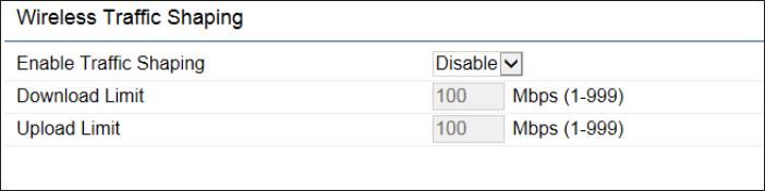
Wireless Trafc Shaping
Trafc shaping regulates the ow of packets leaving an
interface to deliver improved Quality of Service.
Enable Trafc Shaping: Check this option to enable
Wireless Trafc Shaping.
Download Limit: Species the wireless transmission speed
used for downloading.
Upload Limit: Species the wireless transmission speed
used for uploading.
Per User: Check this option to enable wireless trafc
shaping per user function. This function allow users to limit
the maximum download / upload bandwidth for each client
devices on this SSID.
Save: Click Save to conrm the changes.
54
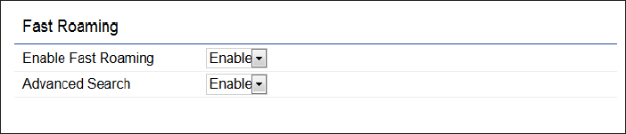
Fast Roaming
Enable the function to serve mobile client devices that roam
from Access Point to Access Point. Some applications running
on Client devices require fast re-association when they roam
to a different Access Point
Please enter the settings of the SSID and initialize the Security
mode to WPA enterprise, as well as to set the Radius Server
rstly. Users can enable the Fast Roaming and implement the
advanced search.
Please also set the same enterprise Encryption under
the same SSID on other Access Points and enable the
Fast Roaming. When the conguration is realized on
different Access Point, the mobile client devices can run
the voice service and require seamless roaming to prevent
delay in conversation from Access Point to Access Point.
Enable Fast Roaming: Enable or disable fast roaming
feature.
Enable Advanced Search: Enable or disable advanced
search feature.
55
Mesh SSID: To create a mesh network, please enter the
Mesh SSID of the Access Point that you wish to include in
the Mesh.
Security: Select None or WPA2-PSK AES from drop-down
list.
Mesh Settings- ENH1750EXT
AES Passphrase: Enter the key values you wish to uses.
Other Access Points must use the same key to establish
a mesh link
56
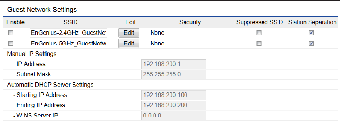
Guest Network Settings
Adding a guest network allows visitors to use the Internet
without giving out your ofce or company wireless
security key. You can add a guest network to each wireless
network in the 2.4 GHzb/g/n and 5 GHza/n frequencies.
SSID: Specied the SSID for the current prole.. Choices
given are: Disabled, Deny MAC in the list, or Allow MAC in
the list.
Hidden SSID: Check this option to hide SSID from clients, If
checked, this SSID will not appear in the AP detect.
Client Isolation: Click the appropriate radio button to allow
or prevent communication between client devices.
IP address: The IP Address of this device.
Subnet Mask: The IP Subnet mask of this device.
Starting IP Address: The rst IP Address in the range of
the addresses by the DHCP server.
Ending IP Address: The last IP Address in the range of
addresses assigned by the DHCP server.

57
Enable : Enable the Fast Handover feature by ensuring that
each client is served by at least one Access Point at any
time. Access Points continuously monitor the connectivity
quality of any client in their range and efciently share
this information with other Access Points in the vincinity
of that client to coordinate which of them should serve the
client best.
RSSI: Enter the RSSI (Received Signal Strength Index) in
order to determine the handover procedure which the
current wireless link will terminate. RSSI is an indication of
the power level being received by the antenna. Therefore,
the higher the RSSI number, the stronger the signal.
RSSI Threshold
58
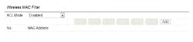
Wireless MAC Filtering is used to allow or deny network
access to wireless clients (computers, tablet PCs, NAS,
smartphones, etc.) according to their MAC addresses. You
can manually add a MAC address to restrict permission to
access EAP1750H. The default setting is: Disable Wireless
MAC Filter.
Note: Only applicable in Access Point and WDS AP mode.
ACL (Access Control List) Mode: Determines whether
network access is granted or denied to clients whose MAC
addresses appear in the MAC address table on this page.
Choices given are: Disabled, Deny MAC in the list, or Allow
MAC in the list.
MAC Address: Enter the MAC address of the wireless client
you wish to congure for.
Add: Click Add to add the MAC address to the MAC Address
table.
Delete: Deletes the selected entries.
Save: Click Save to apply the changes.
Wireless MAC Filtering
59
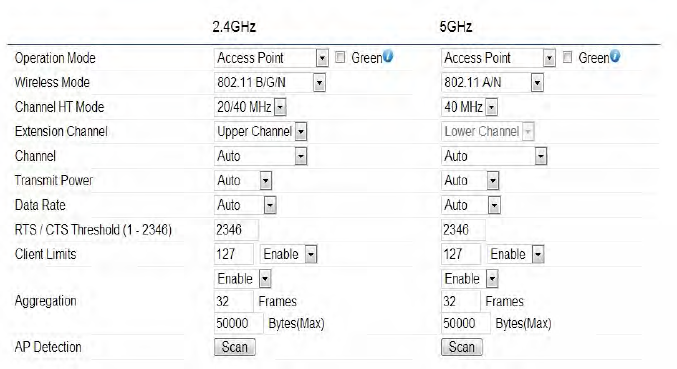
Wireless Advanced
This page allows you to congure advanced wireless
settings for the EWS550AP/EWS510AP/EWS511AP. It is
recommended that the default settings are used unless
the user has experience with more advanced networking
features.
2.4 GHz/5 GHz Wireless Advanced
Data Rate: Select a data rate from the drop-down list. The
data rate affects throughput of data in the EAP1750H.
The lower the data rate, the lower the throughput, though
transmission distance will be lowered as well.
Transmit Power: Sets the power output of the wireless
signal.
RTS/CTS Threshold: Species the threshold package size
for RTC/CTS. A smaller number causes RTS/CTS packets to
be sent more often and in turn consumes more bandwidth.
Distance: Species the distance between Access Points
and clients. Longer distances may drop high-speed
connections.
Aggregation: Merges data packets into one packet. This
option reduces the number of packets, but increases packet
sizes.
Save: Click Save to conrm the changes.

60
Chapter 8
Management
61
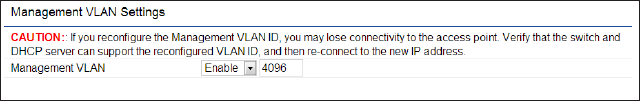
Management VLAN Settings
This page allows you to assign a VLAN tag to packets sent
over the network. A VLAN is a group of computers on a
network whose software has been congured so that they
behave as if they were on a separate Local Area Network
(LAN). Computers on VLAN do not have to be physically
located next to one another on the LAN.
Note: Only applicable in Access Point and WDS AP
modes.
Management VLAN: If your network includes VLANs, you
can enable Management VLAN ID for packets passing
through the Access Point with a tag.
Save: Click Save to conrm the changes or Cancel to cancel
and return to previous settings.
Note: If you recongure the Management VLAN ID, you
may lose your connection to this AP. Verify that the
DHCP server supports the recongured VLAN ID and
then reconnect to this AP using the new IP address.
62
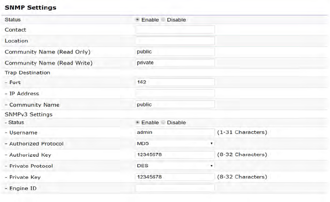
SNMP Settings
This page allows you to assign the Contact Details, Location,
Community Name, and Trap Settings for a Simple Network
Management Protocol (SNMP). SNMP is a networking
management protocol used to monitor network attached
devices. SNMP allows messages (called protocol data units)
to be sent to various parts of the network. Upon receiving
these messages, SNMP compatible devices (called agents)
returns the data stored in their Management Information
Bases.
SNMP Enable/Disable: Enables or disables the SNMP
feature.
Contact: Species the contact details of the device.
Location: Species the location of the device.
Community Name (Read Only): Species the password
for the SNMP community for read only access.
Community Name (Read/Write): Species the password
for the SNMP community with read/write access.
Trap Destination Address: Species the IP address of the
computer that will receive the SNMP traps.
Trap Destination Community Name: Species the
password for the SNMP trap community.
SNMPv3: Enables or disables the SNMPv3 feature.
User Name: Species the username for SNMPv3.
Auth Protocol: Selects the authentication protocol type:
MDS or SHA.
Auth Key: Species the authentication key.
Priv Protocol: Selects the privacy protocol type: DES.
Priv Key: Species the privacy key for privacy.
Engine ID: Species the engine ID for SNMPv3.
Apply Save: Click Apply Save to apply the changes.
Advanced Settings
63
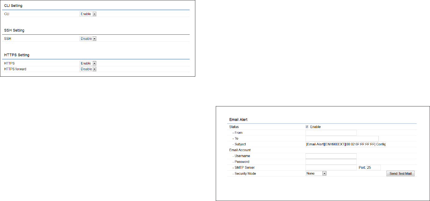
CLI Settings
CLI: The Command Line Interface (CLI) allows you to type
commands instead of choosing them from a menu or
selecting an icon.
SSH: Enable Secure Shell (SSH) to make secure, encrypted
connections in the network. Secure Shell is a network
protocol that allows data to be exchanged using a secure
channel between two network devices.
HTTPS: Enable HTTPS to transfer and display web content
securely. The Hypertext Transfer Protocol over SSL (Secure
Socket Layer) is a TCP/IP protocol used by web servers to
transfer and display web content securely.
Email Alert
You can use the Email Alert feature to send messages
to the congured email address when particular system
events occur.
Note: Do NOT use your personal email address as it can
unnecessarily expose your personal email login credentials.
Use a separate email account made for this feature instead.
Status: Enable this function for further settings.
From: Enter the email address to show the sender of the
email.
To: Enter the address to receive email alerts.
Subject: Enter the text to appear in the email subject line.
64
Username: Enter the username for the email account that
will be used to send emails.
Password: Enter the password for the email account that
will be used to send emails.
SMTP Server: Enter the IP address or hostname of the
outgoing SMTP server.
Port: Enter the SMTP port number to use for outbound
emails.
65
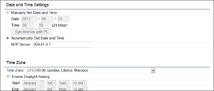
Time Setting
This page allows you to set the internal clock of the AP.
Manually Set Date and Time: Manually specify the
date and time.
Synchorize with PC: Click this button to synchorize
Date and time of this AP with the PC.
Automatically Get Date and Time: Select
Automatically Get Date and Time and check whether
you wish to enter the IP address of an NTP server or
use the default NTP server to have the internal clock
set automatically.
Time Zone: Choose a time zone to implement the
service for this AP.
Enable Daylight Saving: Check whether daylight
savings applies to your area.
Start: Select the day, month, and time when daylight
savings time starts.
Enable Daylight Saving: Select the day, month, and time
when daylight savings times ends.
Time Zone
66
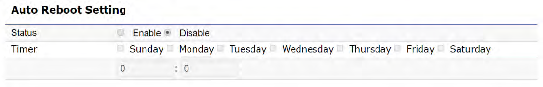
Auto Reboot Settings
You can specify how often you wish to reboot the AP.
Auto Reboot Setting: Enables or disables the Auto
Reboot function.
Timer: Select the day and enter the time you would like
to reboot automatically.
Save: Click Save to apply the changes.
67
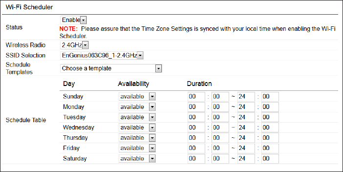
Wi-Fi Scheduler
The Wi-Fi Scheduler can be created for use in enforcing
rules. For example, if you wish to restrict web access to
Mon-Fri from 3pm to 8pm, you could create a schedule
selecting Mon, Tue, Wed, Thu and Fri while entering a Start
time of 3pm and End Time of 8pm to limit access to these
times.
Status: Enables or disables the Wi-Fi scheduler function.
Wireless Radio: Select 2.4 GHz or 5 GHz from the drop-
down list for the preferred band type.
SSID Selection: Select a SSID from the drop-down list.
Schedule Templates: Select a schedule template from the
drop-down list.
Day(s): Place a checkmark in the boxes for the desired days
or select the All Week radio button to select all seven days
of the week.
Duration: The Start Time is entered in two elds. The rst
box is for hours and the second box is for minutes. The End
Time is entered in the same format as the Start time.
68
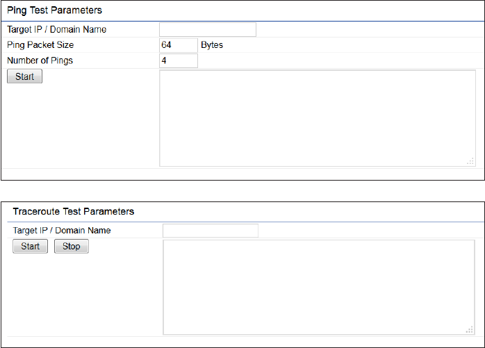
Ping Test Parameters
This page allows you to analyze the connection quality
of the AP and trace the routing table to a target in the
network.
Target IP: Enter the IP address you would like to search.
Ping Packet Size: Enter the packet size of each ping.
Number of Pings: Enter the number of times you wish to
ping.
Start Ping: Click Start Ping to begin pinging the target
device (via IP).
Traceroute Target: Enter the IP address or domain name
you wish to trace.
Start Traceroute: Click Start Traceroute to begin the trace
route operation.
Tools
69
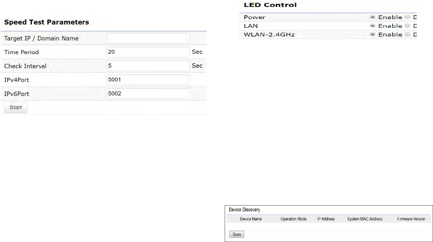
Speed Test Parameters / LED Control
This page allows you to analyze the connection quality
of the AP and trace the routing table to a target in the
network.
Target IP / Domain Name: Enter an IP address or domain
name you wish to impelement a speed test for realizing
the variance on wireless speed.
Time Period: Enter the time in seconds that you would like
the test to implement for and in how many intervals.
IPv4/IPv6 Port: This Access Points uses IPv4 5001 and
IPv6 5002 port for the speed test.
Start: Click start to implement speed test.
LED Control
Control LED on/off for Power, LAN interface, or 2.4 GHz/5
GHz WLAN interface.
Power: Enables or disables the Power LED indicator.
LAN: Enables or disables the LAN LED indicator.
WLAN-2.4 GHz: Enables or disables the WLAN-2.4 GHz LED
indicator.
WLAN-5 GHz: Enables or disables the WLAN-5 GHz LED
indicator.
Device Discovery
This page allows you to discover devices from network
for Operation Mode, IP Address, System MAC Address and
Firmware version.
70
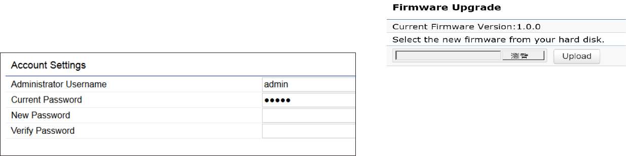
This page allows you to change the AP username and
password. By default, the username is: admin and the
password is: admin. The password can contain from 0 to
12 alphanumeric characters and is case sensitive.
Account Settings
Administrator Username: Enter a new username for
logging in to the New Name entry box.
Current Password: Enter the old password for logging in
to the Old Password entry box.
New Password: Enter the new password for logging in to
the New Password entry box.
Verify Password: Re-enter the new password in the
Conrm Password entry box for conrmation.
Apply: Click Apply to apply the changes.
Firmware Upgrade
This page allows you to upgrade the firmware of the
AP.
To Perform the Firmware Upgrade:
1. Click the Choose File button and navigate the OS le
system to the location of the upgrade le.
2. Select the upgrade le. The name of the le will appear
in the Upgrade File eld.
3. Click the Upload button to commence the rmware
upgrade.
Note: The device is unavailable during the Firmware
upgrade process and must restart when the upgrade is
completed. Any connections to or through the device
will be lost.
Account Firmware
71
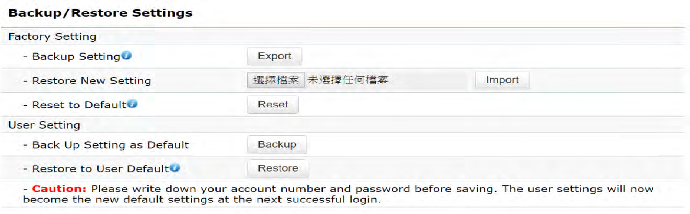
Backup/Restore
This page allows you to save the current device
configurations. When you save your configurations,
you also can reload the saved configurations into the
device through the Restore Saved Settings from a file
section. If extreme problems occur, or if you have set
the AP incorrectly, you can use the Reset button in the
Revert to Factory Default Settings section to restore
all the configurations of the AP to the original default
settings.
Backup Setting: Click Export to save the current
configured settings.
Restore New Setting: To restore settings that have
been previously backed up, click Browse, select the
file, and click Restore.
Restore to Default: Click Reset button to restore the
ENH1750EXT to its factory default settings.

72
User Setting
The function allows you to backup the current device
configurations into the AP as the default value. If
extreme problems occur, or if you have set the AP
incorrectly, you can push the Reset button to revert all
the configurations of the AP to the user default.
Back Up Setting as Default: Click Backup to backup
the user settings you would like to the device’s memory
for the default settings.
Restore to User Default: Click Restore to restore user
settings to the factory standard settings.
Note1: After setting the current settings as the default, you should click the Restore to Default on the
web interface for reverting the settings into the factory default instead of pushing the reset button.
Note2: Please write down your account and password before saving. The user settings will now become
the new default settings at the next successful login.
73
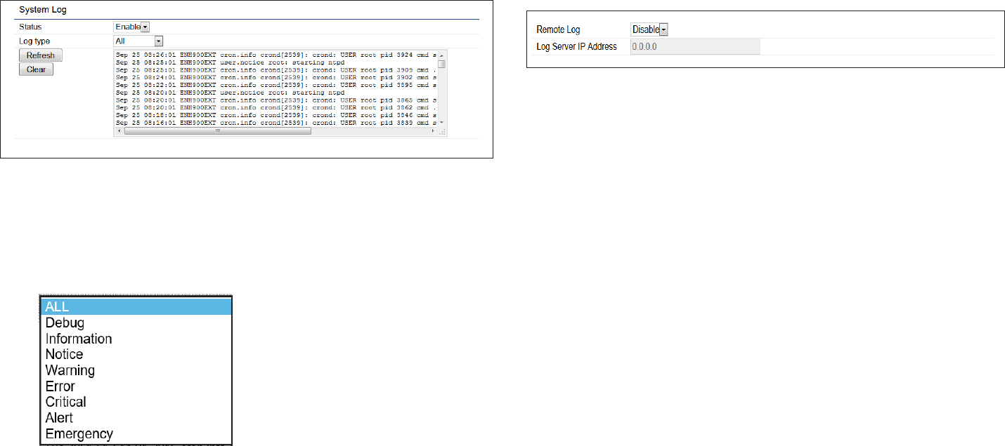
System Log
The AP automatically logs (records) events of possible
interest are in its internal memory. To view the logged
information, click the Log link under the System Manager
menu. If there is not enough internal memory to log all
events, older events are deleted from the log. When
powered down or rebooted, the log will be cleared.
Status: Enable/Disable this function.
Log type: You may choose one of log types to display logs
in the following window. The default log types is All.
Remote Log
This page allows you to setup the Remote Log functions
for the AP.
Remote Log: Enable/disable this function.
Log Server IP Address: Enter the IP address of the log
server.
Apply: Click Apply to apply the changes.
Log
74
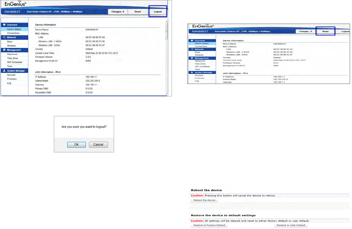
Logout
Logout: Click Logout in Management menu to logout.
Please conrm again to logout the system or not.
Reset
In some circumstances, it may be required to force the
device to reboot. Click on Reset to reboot the AP
Once you click reset button, you will see the options for
reboot or restore this AP.
Reboot the device: Click it to reboot this device.
Restore to Factory Default: Click it to reset this device to
factory default setting.
Restore to User Default: Click it to reset this device to user
default settings. For realizing the setting method, you may
refer page 74 and page 75.
75
Appendix

76
Federal Communication Commission Interference Statement
This equipment has been tested and found to comply with the limits for a Class B digital device, pursuant to Part 15 of the FCC Rules. These limits are
designed to provide reasonable protection against harmful interference in a residential installation. This equipment generates, uses and can radiate
radio frequency energy and, if not installed and used in accordance with the instructions, may cause harmful interference to radio communications.
However, there is no guarantee that interference will not occur in a particular installation. If this equipment does cause harmful interference to radio
or television reception, which can be determined by turning the equipment o and on, the user is encouraged to try to correct the interference by
one of the following measures:
• Reorientorrelocatethereceivingantenna.
• Increasetheseparationbetweentheequipmentandreceiver.
• Connecttheequipmentintoanoutletonacircuitdierentfromthattowhichthereceiverisconnected.
• Consultthedealeroranexperiencedradio/TVtechnicianforhelp
FCC Caution:
Any changes or modications not expressly approved by the party responsible for compliance could void the user’s authority to operate
this equipment.
This device complies with Part 15 of the FCC Rules. Operation is subject to the following two conditions: (1) This device may not cause harmful
interference, and (2) this device must accept any interference received, including interference that may cause undesired operation.
IMPORTANT NOTE:
Radiation Exposure Statement
This equipment complies with FCC radiation exposure limits set forth for an uncontrolled environment. This equipment should be installed and
operated with a minimum distance of 20 cm between the radiator & your body.
This transmitter must not be co-located or operating in conjunction with any other antenna or transmitter. Operation of this device is restricted to
indoor use only.
Appendix A

77
Industry Canada statement
This device complies with RSS-247 of the Industry Canada Rules. Operation is subject to the following two conditions: (1) This device
may not cause harmful interference, and (2) this device must accept any interference received, including interference that may cause
undesired operation.
Ce dispositif est conforme à la norme CNR-247 d’Industrie Canada applicable aux appareils radio exempts de licence. Son fonctionnement
est sujet aux deux conditions suivantes: (1) le dispositif ne doit pas produire de brouillage préjudiciable, et (2) ce dispositif doit accepter
tout brouillage reçu, y compris un brouillage susceptible de provoquer un fonctionnement indésirable.
Caution:
(i) the device for operation in the band 5150-5250 MHz is only for indoor use to reduce the potential for harmful interference to co-
channel mobile satellite systems;
(ii) high-power radars are allocated as primary users (i.e. priority users) of the bands 5250-5350 MHz and 5650-5850 MHz and that these
radarscouldcauseinterferenceand/ordamagetoLE-LANdevices.
(iii) Users should also be advised that high-power radars are allocated as primary users (i.e. priority users) of the bands 5650-5850 MHz
andthattheseradarscouldcauseinterferenceand/ordamagetoLE-LANdevices.
Avertissement:
(i) les dispositifs fonctionnant dans la bande 5150-5250 MHz sont réservés uniquement pour une utilisation à l’intérieur an de réduire
les risques de brouillage préjudiciable aux systèmes de satellites mobiles utilisant les mêmes canaux;
(ii) De plus, les utilisateurs devraient aussi être avisés que les utilisateurs de radars de haute puissance sont désignés utilisateurs
principaux (c.-à-d., qu’ils ont la priorité) pour les bandes 5250-5350 MHz et 5650-5850 MHz et que ces radars pourraient causer du
brouillageet/oudesdommagesauxdispositifsLAN-EL.
(iii) De plus, les utilisateurs devraient aussi être avisés que les utilisateurs de radars de haute puissance sont désignés
utilisateurs principaux (c.-à-d., qu’ils ont la priorité) pour les bandes 5650-5850 MHz et que ces radars pourraient causer du
brouillageet/oudesdommagesauxdispositifsLAN-EL.
Appendix B - IC Interference Statement
78
FOR MOBILE DEVICE USAGE
Radiation Exposure Statement
This equipment complies with IC radiation exposure limits set forth for an uncontrolled environment. This equipment should be installed and operated
with a minimum distance of 20cm between the radiator & your body.
Pour l’utilisation de dispositifs mobiles)
Déclaration d’exposition aux radiations:
Cet équipement est conforme aux limites d’exposition aux rayonnements IC établies pour un environnement non contrôlé. Cet équipement doit
être installé et utilisé avec un minimum de 20cm de distance entre la source de rayonnement et votre corps.
79
Appendix C - CE Interference Statemen
Europe – EU Declaration of Conformity
ThisdevicecomplieswithDirective2014/53/EUissuedbytheCommissionoftheEuropeanCommunity.
- Declaration of Conformity
Please added certication standard in your user manual which depended on the test standards your device performed. or
- If the DoC should be a simplied version, please take below as reference –
Hereby,EnGeniusNetworksdeclaresthattheEWS550AP/EWS510AP/EWS511APareincompliancewithDirective2014/53/EU.
The full text of the EU declaration of conformity is available at the following internet address:
Importer:EnGeniusNetworksEuropeB.V.
Importer Address: ESP 240, 5633 AC Eindhoven, The Netherlands
Manufacturer : EnGenius Networks. Inc.
Manufacturer Address: No.500, Fusing 3rd Rd., Hwa-Ya Technology Park Kuei-Shan Dist., Taoyuan City, Taiwan (R.O.C.)
CEDoCLink:https://www.engeniusnetworks.eu/ens500ext-ac-ens500-ac-enstation5-accedoc
80
Appendix D -Professional installation instruction
1. Installation personal
This product is designed for specic application and needs to be installed by a qualied personal who has RF and related rule knowl-
edge. The general user shall not attempt to install or change the setting.
2. Installation location
The product shall be installed at a location where the radiating antenna can be kept 20cm from nearby person in normal operation con-
dition to meet regulatory RF exposure requirement.
3. External antenna
Use only the antennas which have been approved by the applicant. The non-approved antenna(s) may produce unwanted spurious or
excessiveRFtransmittingpowerwhichmayleadtotheviolationofFCC/IClimitandisprohibited.
4. Installation procedure
Please refer to user’s manual for the detail.
5. Warning
Please carefully select the installation position and make sure that the nal output power does not exceed the limit set force in relevant
rules. The violation of the rule could lead to serious federal penalty.