EnGenius Technologies ENS200 Secured Wireless Access Point User Manual ENS200
EnGenius Technologies Secured Wireless Access Point ENS200
Contents
- 1. User Man (ENS200)-1
- 2. User Man (ENS200)-2
- 3. User Man (ERA150)
- 4. User Man (FAP-112B)
User Man (ENS200)-2
BASIC NETWORK SETTINGS CONFIGURING IP SETTINGS
4-10
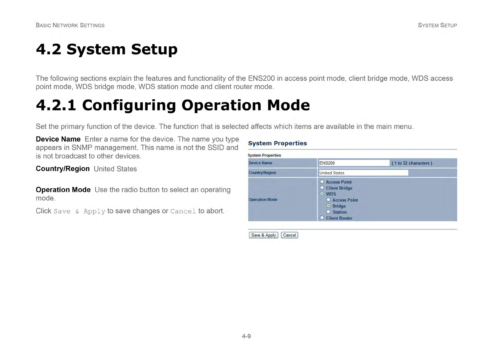
4.2.2 Configuring IP Settings
Configure the LAN settings for the ENS200 using a static or dynamic IP address.
IP Network Setting Configure the network connection type
using either a static IP or dynamic IP.
IP Address Enter the LAN IP address of the ENS200.
Subnet Mask Enter the subnet mask of the ENS200.
Default Gateway Enter the default gateway of the ENS200.
Primary DNS Enter the primary DNS address of the ENS200.
Secondary DNS Enter the secondary DNS address of the
ENS200.
Click Apply to save the settings or Cancel to discard changes.
BASIC NETWORK SETTINGS CONFIGURING SPANNING TREE SETTINGS
4-11
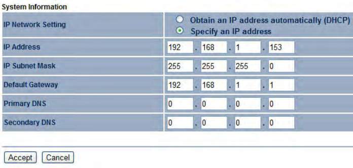
4.2.3 Configuring Spanning Tree Settings
Spanning Tree Status Enable or disable the ENS200
Spanning Tree function.
Bridge Hello Time Specify Bridge Hello Time, in seconds. This
value determines how often the ENS200 sends hello packets to
communicate information about the topology throughout the
entire Bridged Local Area Network
Bridge Max Age Specify Bridge Max Age, in seconds. If
another bridge in the spanning tree does not send a hello packet
for a long period of time, it is assumed to be dead.
Bridge Forward Delay Specify Bridge Forward Delay, in
seconds. Forwarding delay time is the time spent in each of the
Listening and Learning states before the Forwarding state is
entered. This delay is provided so that when a new bridge
comes onto a busy network, it looks at some traffic before
participating.
Priority Specify the Priority number. Smaller numbers have
greater priority.
Click Accept to confirm the changes or Cancel to cancel and return
previous settings.
BASIC NETWORK SETTINGS ROUTER SETUP
4-12
4.3 Router Setup
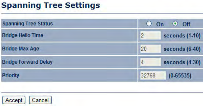
4.3.1 Configuring WAN Settings
Configure the WAN settings for the ENS200 using a static or dynamic IP address, PPPoE or PPTP.
Static IP
Setting a static IP address allows an administrator to set a specific IP address for the router and guarantees that it can not be
assigned a different address.
Account Name Enter the account name provided by your ISP
Domain Name Enter the domain name provided by your ISP
MTU The maximum transmission unit (MTU) specifies the
largest packet size permitted for an internet transmission. The
factory default MTU size for static IP is 1500. The MTU size
can be set between 512 and 1500.
IP Address Enter the router’s WAN IP address.
Subnet Mask Enter the router’s WAN subnet mask.
Default Gateway Enter the WAN gateway address.
Primary DNS Enter the primary DNS server address.
Secondary DNS Enter the secondary DNS server address.
Discard Ping on WAN Check to Enable to recognize pings on
the ENS200 WAN interface or Disable to block pings on the
BASIC NETWORK SETTINGS DYNAMIC IP
4-13
ENS200 WAN interface. Note: Pinging IP addresses is a common method used by hackers to test whether the IP address is valid.
Blocking pings provides some extra security from hackers.
Click Accept to save the settings or Cancel to discard changes.
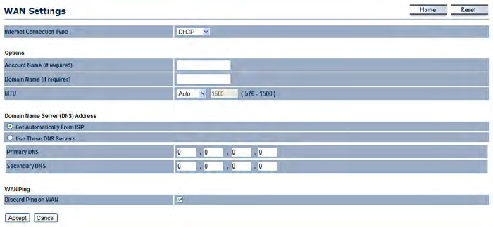
Dynamic IP
Dynamic IP addressing assigns a different IP address each time a device connects to an ISP service provider. The service is most
commonly used by ISP cable providers.
Account Name Enter the account name provided by your ISP
Domain Name Enter the domain name provided by your ISP
MTU The maximum transmission unit (MTU) specifies the
largest packet size permitted for an internet transmission. The
factory default MTU size for static IP is 1500. The MTU size can
be set between 512 and 1500.
Get Automatically From ISP Click the radio button to obtain
the DNS automatically from the DHCP server.
Use These DNS Servers Click the radio button to set up the
Primary DNS and Secondary DNS servers manually.
Discard Ping on WAN Check to Enable to recognize pings on
the ENS200 WAN interface or Disable to block pings on the
ENS200 WAN interface. Note: Pinging IP addresses is a
common method used by hackers to test whether the IP
address is valid. Blocking pings provides some extra security
from hackers.
Click Accept to save the settings or Cancel to discard
changes.
BASIC NETWORK SETTINGS POINT-TO-POINT PROTOCOL OVER ETHERNET (PPPOE)
4-14
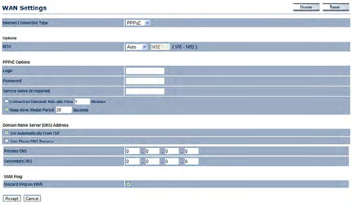
Point-to-Point Protocol over Ethernet (PPPoE)
Point-to-Point Protocol over Ethernet (PPPoE) is used mainly by ISPs that provide DSL modems to connect to the Internet.
MTU Enter the maximum transmission unit (MTU). The MTU
specifies the largest packet size permitted for an internet
transmission (PPPoE default: 1492). The MTU size can be set
between 512 and 1492.
Login Enter the username assigned by an ISP.
Password Enter the password assigned by an ISP.
Service Name Enter the service name of an ISP (optional).
Connect on Demand Select the radio button to specify the
maximum idle time. Internet connection will disconnect when it
reach the maximum idle time, but it will automatically connect
when user tries to access the network.
Keep Alive Select whether to keep the Internet connection
always on, or enter a redial period once the internet lose
connection.
BASIC NETWORK SETTINGS POINT-TO-POINT PROTOCOL OVER ETHERNET (PPPOE)
4-15
Get Automatically From ISP Click the radio button to obtain
the DNS automatically from the DHCP server.
Use These DNS Servers Click the radio button to set up the
Primary DNS and Secondary DNS servers manually.
Discard Ping on WAN Check to Enable to recognize pings on
the ENS200 WAN interface or Disable to block pings on the
ENS200 WAN interface. Note: Pinging IP addresses is a
common method used by hackers to test whether the IP
address is valid. Blocking pings provides some extra security
from hackers.
Click Accept to save the settings or Cancel to discard
changes.
BASIC NETWORK SETTINGS POINT-TO-POINT TUNNELLING PROTOCOL (PPTP)
4-16
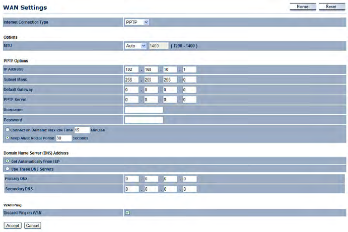
Point-to-Point Tunnelling Protocol (PPTP)
The point-to-point tunnelling protocol (PPTP) is used in association with virtual private networks (VPNs). There a two parts to a PPTP
connection: the WAN interface settings and the PPTP settings.
MTU Enter the maximum transmission unit
(MTU). The MTU specifies the largest packet
size permitted for an internet transmission
(PPPoE default: 1492). The MTU size can be set
between 512 and 1492.
IP Address Enter the router’s WAN IP address.
Subnet Mask Enter the router’s WAN subnet IP address.
Default Gateway Enter the router’s WAN gateway IP address.
PPTP Server Enter the IP address of the PPTP server.
Username Enter the username provided by your ISP.
Password Enter the password provided by your ISP.
Connect on Demand If you want the ENS200 to end the
Internet connection after it has been inactive for a period of
time, select this option and enter the number of minutes you
want that period of inactivity to last.
BASIC NETWORK SETTINGS POINT-TO-POINT TUNNELLING PROTOCOL (PPTP)
4-17
Keep Alive If you want the ENS200 to periodically check your
Internet connection, select this option. Then specify how often
you want the ENS200 to check the Internet connection. If the
connection is down, the ENS200 automatically re-establishes
your connection
Get Automatically From ISP Obtains the DNS automatically
from DHCP server.
Use These DNS Servers Click the radio button to set up the
Primary DNS and Secondary DNS servers manually.
Discard Ping on WAN Check to Enable to recognize pings on
the ENS200 WAN interface or Disable to block pings on the
ENS200 WAN interface. Note: Pinging IP addresses is a
common method used by hackers to test whether the IP
address is valid. Blocking pings provides some extra security
from hackers.
Click Accept to save the settings or Cancel to discard
changes.
BASIC NETWORK SETTINGS CONFIGURING LAN SETTINGS
4-18
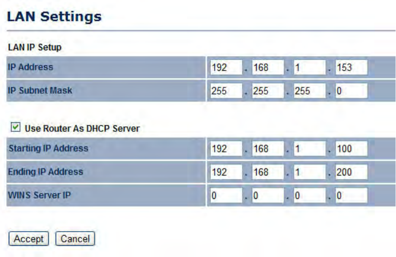
4.3.2 Configuring LAN Settings
IP Address Enter the LAN port IP address.
IP Subnet Mask Enter the LAN IP subnet mask.
WINS Server IP Enter the WINS Server IP.
Use Router As DHCP Server Check this option to
enable the ENS200 internal DHCP server.
Starting IP Address Specify the starting IP
address range for the pool of allocated for private IP
addresses. The starting IP address must be on the
same subnet as the ending IP address; that is the
first three octets specified here must be the same as
the first three octets in End IP Address.
Ending IP Address Specify the ending IP address
range for the pool of allocated for private IP
addresses. The ending IP address must be on the
same subnet as the starting IP address; that is the
first three octets specified here must be the same as
the first three octets in Start IP Address.
WINS Server IP Enter the IP address of the WINS
server.
Click Accept to confirm the changes or Cancel to cancel and return previous settings.
BASIC NETWORK SETTINGS CONFIGURING VPN PASS-THROUGH
4-19
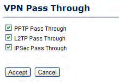
4.3.3 Configuring VPN Pass-Through
VPN Pass-through allows a secure virtual private network (VPN) connection between two computers. Enabling the options on this
page opens a VPN port and enables connections to pass through the ENS200 without interruption.
PPTP Pass-through Check this option to enable PPTP pass-through mode.
L2TP Pass-through Check this option to enable L2TP pass-through mode.
IPSec Pass-through Check this option to enable IPSec pass-through mode.
Click Accept to confirm the changes or Cancel to cancel and return previous settings.
BASIC NETWORK SETTINGS CONFIGURING PORT FORWARDING
4-20
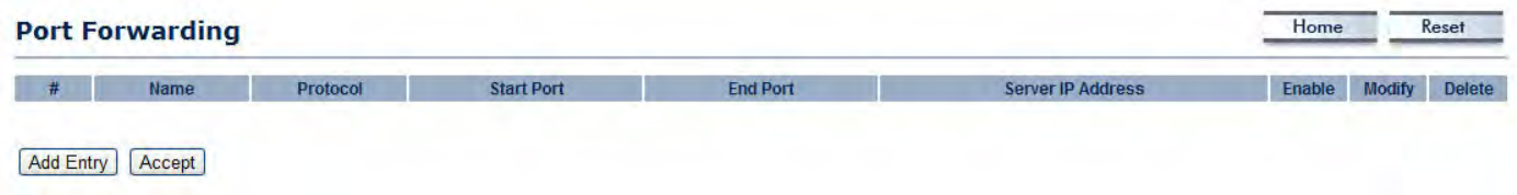
4.3.4 Configuring Port Forwarding
Port forwarding enables multiple server applications on a LAN to serve clients on a WAN over a single WAN IP address. The router
accepts incoming client packets, filters them based on the destination WAN, or public, port and protocol and forwards the packets to
the appropriate LAN, or local, port. Unlike the DMZ feature, port forwarding protects LAN devices behind the firewall.
NO. Displays the sequence number of the forwarded port.
Name Displays the name of the forwarded port.
Protocol Displays the protocol to use for mapping from the following: TCP, UDP or Both.
Start Port Displays the LAN port number that WAN client packets will be forward to.
End Port Displays the port number that the WAN client packets are received.
Server IP Displays the IP address of the server for the forwarded port.
Enable Click to enable or disable the forwarded port profile
Modify Click to modify the forwarded port profile
Delete Click to delete the forwarded port profile
Click Add Entry to add port forwarding rules
Click Accept to confirm the changes.
BASIC NETWORK SETTINGS CONFIGURING PORT FORWARDING
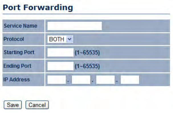
4-21
Service Name Enter a name for the port forwarding rule.
Protocol Select a protocol for the application: Choices are Both, TCP,
and UDP.
Starting Port Enter a starting port number.
Ending Port Enter an ending port number. All ports numbers between
the starting and ending ports will forward users to the IP address
specified in the IP Address field.
IP Address Enter the IP address of the server computer on the LAN
network where users will be redirected.
Click Save to apply the changes or Cancel to return previous settings.

BASIC NETWORK SETTINGS CONFIGURING DEMILITARIZED ZONE
4-22
4.3.5 Configuring Demilitarized Zone
Configuring a device on the LAN as a demilitarized zone (DMZ) host allows unrestricted two-way Internet access for Internet applica-
tions, such as online video games, to run from behind the NAT firewall. The DMZ function allows the router to redirect all packets
going to the WAN port IP address to a particular IP address on the LAN. The difference between the virtual server and the DMZ func-
tion is that a virtual server redirects a particular service or Internet application, such as FTP, to a particular LAN client or server,
whereas a DMZ redirects all packets, regardless of the service, going to the WAN IP address to a particular LAN client or server.
DMZ Hosting Select Enable DMZ to activate DMZ
functionality.
DMZ Address Enter an IP address of a device on
the LAN.
Click Accept to confirm the changes or Cancel to
cancel and return previous settings.
WARNING!
The PC defined as a DMZ host is not protected by the firewall and is vulnerable to malicious network attacks. Do not store or
manage sensitive information on the DMZ host.
!

BASIC NETWORK SETTINGS CONFIGURING WIRELESS LAN
4-23
4.4 Configuring Wireless LAN
4.4.1 Configuring Wireless Settings
Instructions on how to configure the wireless and security settings for each of the possible operating modes.
Access Point Mode
The ENS200 supports Access Point Mode. In this mode, users with a wireless client device within range can connect to the ENS200
to access the WLAN
WARNING!
Incorrectly changing these settings may cause the device to stop functioning. Do not modify the settings in this section without a
thorough understanding of the parameters.
!
BASIC NETWORK SETTINGS ACCESS POINT MODE
4-24
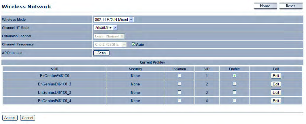
Wireless Mode Wireless
mode supports 802.11b/g/n
mixed modes.
Channel HT Mode The
default channel bandwidth is
40 MHz. The larger the
channel, the better the
transmission quality and
speed.
Extension Channel Select
upper or lower channel. Your
selection may affect the Auto
channel function.
Channel / Frequency
Select the channel and
frequency appropriate for your country’s regulation.
Auto Check this option to enable auto-channel selection.
AP Detection AP Detection can select the best channel to use by scanning nearby areas for Access Points.
Current Profile Configure up to four different SSIDs. If many client devices will be accessing the network, you can arrange the
devices into SSID groups. Click Edit to configure the profile and check whether you want to enable extra SSIDs.
Click Accept to confirm the changes or Cancel to cancel and return previous settings.
BASIC NETWORK SETTINGS ACCESS POINT MODE
4-25
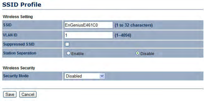
SSID Specify the SSID for the current profile.
VLAN ID Specify the VLAN tag for the current profile.
Suppressed SSID Check this option to hide the SSID from
clients. If checked, the SSID will not appear in the site survey.
Station Separation Click the appropriate radio button to allow
or prevent communication between client devices.
Wireless Security See the Wireless Security section.
Click Save to accept the changes or Cancel to cancel and
return previous settings.
BASIC NETWORK SETTINGS CLIENT BRIDGE MODE
4-26
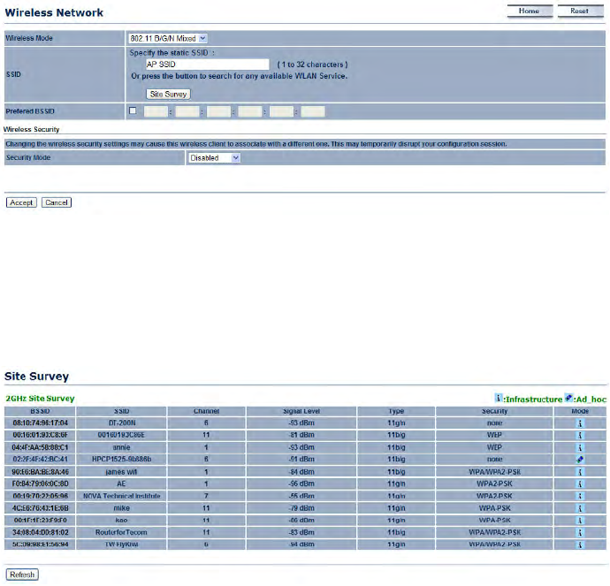
Client Bridge Mode
Client Bridge Mode lets you connect two LAN segments via a wireless link as though they are on the same physical network. Since
the computers are on the same subnet, broadcasts reach all machines. As a result, DHCP information generated by the server reach
all client computers as though the clients residing on one physical network.
Wireless Mode Wireless mode supports 802.11b/g/n mixed
modes.
SSID Specify the SSID if known. This field is completed
automatically if you select an Access Point in the Site Survey.
Site Survey Scans nearby locations for Access Points. You
can select a discovered Access Point to establish a connection.
Prefer BSSID Enter the MAC address if known. If you select an
Access Point in the Site Survey, this field is completed
automatically.
Wireless Security See section 8.2 for information.
Click Accept to confirm the changes or Cancel to cancel and return previous settings.
Profile If you used the Site Survey, the Web Configurator
shows nearby Access Points. To connect to an Access Point,
click the Access Point’s BSSID.
Wireless Security See Configuring Wireless Security.
Click Refresh to scan again.
BASIC NETWORK SETTINGS WDS BRIDGE MODE
4-27
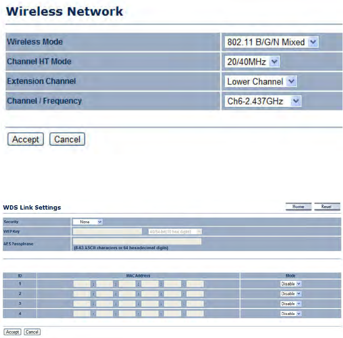
WDS Bridge Mode
Unlike traditional bridging. WDS Bridge Mode allows you to create large wireless networks by linking several wireless access points
with WDS links. WDS is normally used in large, open areas, where pulling wires is cost prohibitive, restricted or physically impossible.
Wireless Mode Wireless mode supports 802.11b/g/n mixed
modes.
Channel HT Mode The default channel bandwidth is 40 MHz.
The larger the channel, the better the transmission quality and
speed.
Extension Channel Select upper or lower channel. Your
selection may affect the Auto channel function.
Channel / Frequency Select the channel and frequency
appropriate for your country’s regulation.
Click Accept to confirm the changes or Cancel to cancel and
return previous settings.
Security Select the type of WDS security: WEP or AES.
WEP Key Enter the WEP key.
AES Pass phrase Enter the AES pass phrase.
MAC Address Enter the MAC address of the Access Point to
which you want to extend wireless connectivity.
Mode Select Disable or Enable to disable or enable WDS.
Click Accept to confirm the changes or Cancel to cancel and
return previous settings.
BASIC NETWORK SETTINGS CLIENT ROUTER MODE
4-28
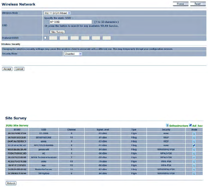
Client Router Mode
In Client Router Mode, you can access the Internet wirelessly with the support of a WISP. In AP Router Mode, the ENS200 can
access the Internet via a cable or DSL modem. In this mode, the ENS200 can be configured to turn off the wireless network name
(SSID) broadcast, so that only stations that have the SSID can be connected. The ENS200 also provides wireless LAN 64/128/156-
bit WEP encryption security, WPA/WPA2, and WPA-PSK/WPA2-PSK authentication, as well as TKIP/AES encryption security. It also
supports VPN pass-through for sensitive data secure transmission.
Wireless Mode Wireless mode supports 802.11b/g/n mixed
modes.
SSID Specify the SSID if known. This field is completed
automatically if you select an Access Point in the Site Survey.
Site Survey Scans nearby locations for Access Points. You can
select a discovered Access Point to establish a connection.
Prefer BSSID Enter the MAC address if known. If you select an
Access Point in the Site Survey, this field is completed
automatically.
Wireless Security See Configuring Wireless Security.
Click Accept to confirm the changes or Cancel to cancel and return previous settings.
Profile If you used the Site Survey, the Web Configurator
shows nearby Access Points. To connect to an Access Point,
click the Access Point’s BSSID.
Wireless Security See Configuring Wireless Security.
Click Refresh to scan again.
BASIC NETWORK SETTINGS CONFIGURING WIRELESS SECURITY
4-29
4.4.2 Configuring Wireless Security
The Wireless Security Settings section lets you configure the ENS200’s security modes: WEP, WPA-PSK, WPA2-PSK, WPA-PSK
Mixed, WPA, WPA2, and WPA Mixed. We strongly recommend you use WPA2-PSK.
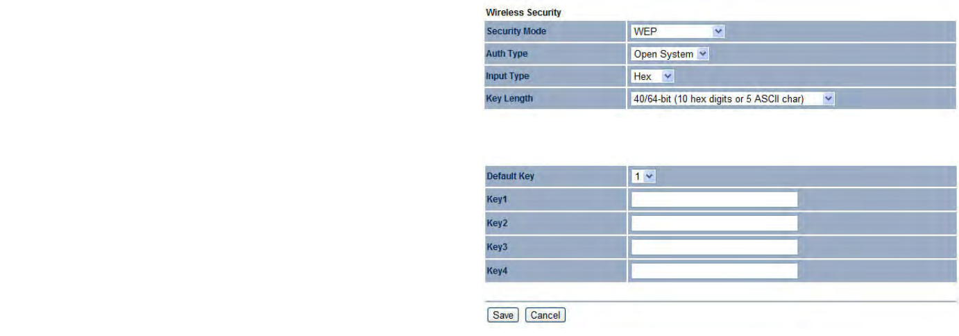
Wired Equivalent Privacy (WEP)
Security Mode Select WEP from the drop-down list to begin
the configuration.
Auth Type Select Open System or Shared.
Input Type Select an input type of Hex or ASCII.
Key Length Level of WEP encryption applied to all WEP keys.
Select a 64/128/152-bit password lengths.
Default Key Specify which of the four WEP keys the ENS200
uses as its default.
Key1 - Key4 Specify a password for the security key index. For
security, each typed character is masked by a dot.
Click Save to save the changes or Cancel to cancel and return
previous settings.
Note:
802.11n does not allow WEP/WPA-PSK/WPA-PSK TKIP security
mode. The connection mode will drop from 802.11n to 802.11g.
BASIC NETWORK SETTINGS WI-FI PROTECTED ACCESS PRE-SHARED KEY (WPA-PSK)
4-30
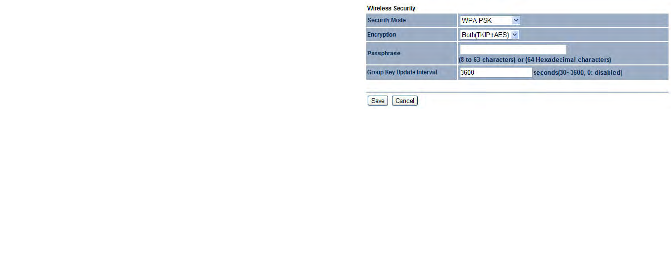
Wi-Fi Protected Access Pre-Shared Key (WPA-PSK)
Security Mode Select WPA-PSK from the drop-down list to
begin the configuration.
Encryption Select Both, TKIP, or AES as the encryption type.
Both = uses TKIP and AES.
TKIP = automatic encryption with WPA-PSK; requires
passphrase.
AES = automatic encryption with WPA2-PSK; requires
passphrase.
Passphrase Specify the security password. For security, each
typed character is masked by a dot.
Group Key Update Interval Specify how often, in seconds, the
group key changes.
Click Save to save the changes or Cancel to cancel and return
previous settings.
Note:
802.11n does not allow WEP/WPA-PSK/WPA-PSK TKIP security
mode. The connection mode will drops from 802.11n to 802.11g.
BASIC NETWORK SETTINGS WI-FI PROTECTED ACCESS 2 PRE-SHARED KEY (WPA2-PSK)
4-31
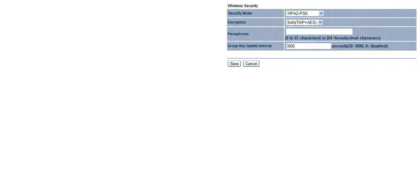
Wi-Fi Protected Access 2 Pre-Shared Key (WPA2-PSK)
Security Mode Select WPA2-PSK from the drop-down list to
begin the configuration.
Encryption Select Both, TKIP, or AES as the encryption type.
Both = uses TKIP and AES
TKIP = automatic encryption with WPA-PSK; requires
passphrase.
AES = automatic encryption with WPA2-PSK; requires
passphrase.
Passphrase Specify the security password. For security, each
typed character is masked by a dot.
Group Key Update Interval Specify how often, in seconds, the
group key changes.
Click Save to save the changes or Cancel to cancel and return
previous settings.
Note:
802.11n does not allow WEP/WPA-PSK/WPA-PSK TKIP security
mode. The connection mode will change from 802.11n to 802.11g.
BASIC NETWORK SETTINGS WI-FI PROTECTED ACCESS PRE-SHARED KEY (WPA-PSK) MIXED
4-32
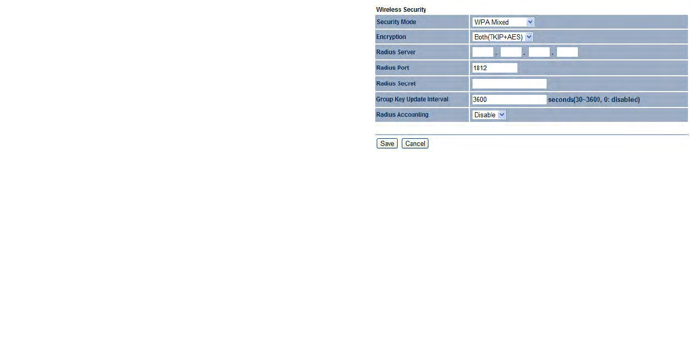
Wi-Fi Protected Access Pre-Shared Key (WPA-PSK) Mixed
Security Mode Select WPA2-PSK Mixed from the drop-down
list to begin the configuration.
Encryption Select Both, TKIP, or AES as the encryption type.
Both = uses TKIP and AES
TKIP = automatic encryption with WPA-PSK; requires
passphrase.
AES = automatic encryption with WPA2-PSK; requires
passphrase.
Radius Server Specify the IP address of the RADIUS server.
Radius Port Specify the port number that your RADIUS server
uses for authentication. Default port is 1812.
Radius Secret Specify RADIUS secret furnished by the
RADIUS server.
Group Key Update Interval Specify how often, in seconds, the
group key changes.
Radius Accounting
Click Save to save the changes or Cancel to cancel and return
previous settings.
Note:
WPA-PSK Mixed can allow multiple security modes at the same time.
802.11n does not allow WEP/WPA-PSK/WPA-PSK TKIP security
mode. The connection mode will change from 802.11n to 802.11g.
BASIC NETWORK SETTINGS WI-FI PROTECTED ACCESS (WPA)
4-33
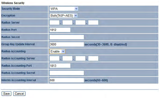
Wi-Fi Protected Access (WPA)
Security Mode Select WPA from the drop-down list to begin
the configuration.
Encryption Select Both, TKIP, or AES as the encryption type.
Both = uses TKIP and AES
TKIP = automatic encryption with WPA-PSK; requires
passphrase.
AES = automatic encryption with WPA2-PSK; requires
passphrase.
Radius Server Specify the IP address of the RADIUS server.
Radius Port Specify the port number that your RADIUS server
uses for authentication. Default port is 1812.
Radius Secret Specify RADIUS secret furnished by the
RADIUS server.
Group Key Update Interval Specify how often, in seconds, the
group key changes.

BASIC NETWORK SETTINGS WI-FI PROTECTED ACCESS (WPA)
4-34
Radius Accounting Select to enable or disable RADIUS
accounting.
Radius Accounting Port Specify the port number that your
RADIUS accounting server uses for authentication. Default port
is 1812.
Radius Accounting Secret Specify RADIUS accounting
secret furnished by the RADIUS server.
Interem Accounting Interval Specify the interem accounting
interval (60 - 600 seconds).
Click Save to save the changes or Cancel to cancel and return
previous settings.
Note:
802.11n does not allow WEP/WPA-PSK/WPA-PSK TKIP security
mode. The connection mode will drops from 802.11n to 802.11g.

BASIC NETWORK SETTINGS WI-FI PROTECTED ACCESS 2 (WPA2)
4-35
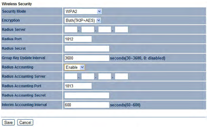
Wi-Fi Protected Access 2 (WPA2)
Security Mode Select WPA from the drop-down list to begin
the configuration.
Encryption Select Both, TKIP, or AES as the encryption type.
Both = uses TKIP and AES
TKIP = automatic encryption with WPA-PSK; requires
passphrase.
AES = automatic encryption with WPA2-PSK; requires
passphrase.
Radius Server Specify the IP address of the RADIUS server.
Radius Port Specify the port number that your RADIUS server
uses for authentication. Default port is 1812.
Radius Secret Specify RADIUS secret furnished by the
RADIUS server.
Group Key Update Interval Specify how often, in seconds, the
group key changes.

BASIC NETWORK SETTINGS WI-FI PROTECTED ACCESS 2 (WPA2)
4-36
Radius Accounting Select to enable or disable RADIUS
accounting.
Radius Accounting Port Specify the port number that your
RADIUS accounting server uses for authentication. Default port
is 1812.
Radius Accounting Secret Specify RADIUS accounting
secret furnished by the RADIUS server.
Interem Accounting Interval Specify the interem accounting
interval (60 - 600 seconds).
Click Save to save the changes or Cancel to cancel and return
previous settings.
Note:
802.11n does not allow WEP/WPA-PSK/WPA-PSK TKIP security
mode. The connection mode will drops from 802.11n to 802.11g.
BASIC NETWORK SETTINGS WI-FI PROTECTED ACCESS (WPA) MIXED
4-37
Wi-Fi Protected Access (WPA) Mixed
Security Mode Select WPA from the drop-down list to begin
the configuration.
Encryption Select Both, TKIP, or AES as the encryption type.
Both = uses TKIP and AES
TKIP = automatic encryption with WPA-PSK; requires
passphrase.
AES = automatic encryption with WPA2-PSK; requires
passphrase.
Radius Server Specify the IP address of the RADIUS server.
Radius Port Specify the port number that your RADIUS server
uses for authentication. Default port is 1812.
Radius Secret Specify RADIUS secret furnished by the
RADIUS server.
Group Key Update Interval Specify how often, in seconds, the
group key changes.

BASIC NETWORK SETTINGS WI-FI PROTECTED ACCESS (WPA) MIXED
4-38
Radius Accounting Select to enable or disable RADIUS
accounting.
Radius Accounting Port Specify the port number that your
RADIUS accounting server uses for authentication. Default port
is 1812.
Radius Accounting Secret Specify RADIUS accounting
secret furnished by the RADIUS server.
Interem Accounting Interval Specify the interem accounting
interval (60 - 600 seconds).
Click Save to save the changes or Cancel to cancel and return
previous settings.
Note:
802.11n does not allow WEP/WPA-PSK/WPA-PSK TKIP security
mode. The connection mode will drops from 802.11n to 802.11g.

BASIC NETWORK SETTINGS CONFIGURING WIRELESS MAC FILTER
4-39
4.4.3 Configuring Wireless MAC Filter
Wireless MAC Filters are used to allow or deny network access to wireless clients according to their MAC addresses. You can manu-
ally add a MAC address to restrict the permission to access ENS200. The default setting is Disable Wireless MAC Filters.
Note:
This section applies to Access Point and WDS Access point mode.
ACL Mode Determines whether network access is granted or
denied to clients whose MAC addresses appear in the MAC
Address table on this page. Choices are Disable, Deny MAC in
the list, or Allow MAC in the list.
MAC Address Filter Enter the MAC address of the device.
Click Add to add the MAC address to the MAC Address table.
Click Apply to apply the changes.

BASIC NETWORK SETTINGS CONFIGURING WDS LINK SETTINGS
4-40
4.4.4 Configuring WDS Link Settings
Using WDS Link Settings, you can create a wireless backbone link between multiple access points that are part of the same wireless
network. This allows a wireless network to be expanded using multiple Access Points without the need for a wired backbone to link
them, as is traditionally required.
Security Select the type of WDS security: WEP or AES.
WEP Key Enter the WEP key.
AES Passphrase Enter the AES passphrase.
MAC Address Enter the MAC address of the Access Point to
which you want to extend wireless connectivity.
Mode Select Disable or Enable to disable or enable WDS.
Click Accept to confirm the changes or Cancel to cancel and
return previous settings.
Note:
The Access Point to which you want to extend wireless connectivity
must enter the ENS200’s MAC address into its configuration. For
more information, refer to the documentation for the Access Point. Not
all Access Point supports this feature.
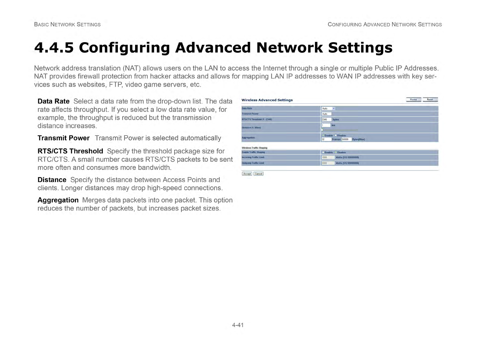
BASIC NETWORK SETTINGS CONFIGURING ADVANCED NETWORK SETTINGS
4-42
Enable Traffic Shaping Check this option to enable wireless
traffic shaping. Traffic shaping regulates the flow of packets
leaving an interface to deliver improved Quality of Service.
Incoming Traffic Limit Specify the wireless transmission
speed used for downloading.
Outgoing Traffic Limit Specify the wireless transmission
speed used for uploading.
Click Accept to confirm the changes or Cancel to cancel and
return previous settings.
BASIC NETWORK SETTINGS MANAGEMENT SETUP
4-43
4.5 Management Setup
The Management section lets you configure administration, management VLAN, SNMP settings, backup/restore settings, firmware
upgrade, time settings, and log settings. This chapter describes these settings.
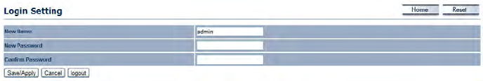
4.5.1 Configuring Administrator Account
Click the Administration link under the Management menu to change the user name and password used to log on to the ENS200
Web Configurator. The default user name is admin and the default password is admin. Changing these settings protects the
ENS200 configuration settings from being accessed by unauthorized users.
Name Enter a new username for logging in to the Web
Configurator.
Password Enter a new password for logging in to the Web
Configurator
Confirm Password Re-enter the new password for
confirmation.
Click Save/Apply to apply the changes or Cancel to return
previous settings.
BASIC NETWORK SETTINGS CONFIGURING ADMINISTRATOR ACCOUNT
4-44
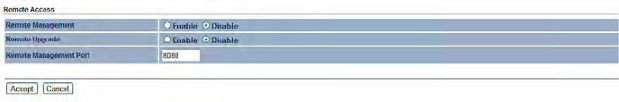
Remote Management Enable or disable remote management.
Remote Upgrade Specify whether the ENS200 firmware can
be upgraded remotely.
Remote Management Port If remote management is enabled,
enter the port number to be used for remote management. For
example: If you specify the port number 8080, enter http://
<IP address>:8080 to access the ENS200 Web
Configurator.
Click Accept to apply the changes or Cancel to return
previous settings.
BASIC NETWORK SETTINGS CONFIGURING MANAGEMENT VLAN
4-45
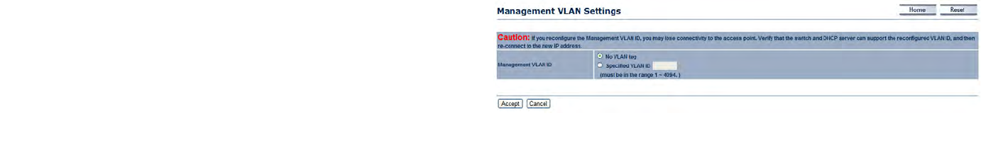
4.5.2 Configuring Management VLAN
Click the Management VLAN link under the Management menu to assign a VLAN tag to the packets. A VLAN is a group of computers
on a network whose software has been configured so that they behave as if they were on a separate Local Area Network (LAN).
Computers on VLAN do not have to be physically located next to one another on the LAN
Management VLAN ID If your network includes VLANs and if
tagged packets need to pass through the Access Point, enter
the VLAN ID. Otherwise, click No VLAN tag.
Click Accept to confirm the changes or Cancel to cancel and
return previous settings.
Note:
If you reconfigure the Management VLAN ID, you may lose your con-
nection to the ENS200. Verify that the DHCP server supports the
reconfigured VLAN ID and then reconnect to the ENS200 using the
new IP address.
BASIC NETWORK SETTINGS CONFIGURING SNMP
4-46
4.5.3 Configuring SNMP
SNMP is used in network management systems to monitor network-attached devices for conditions that warrant administrative atten-
tion.
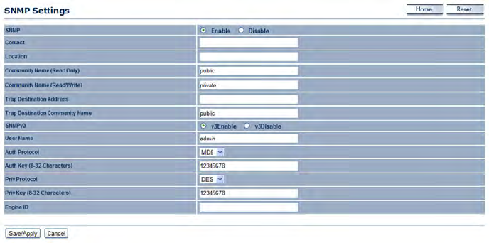
SNMP Enable or disable the ENS200 SNMP function.
Contact Enter the contact details of the device.
Location Enter the location of the device.
Community Name (read only) Enter the password for
accessing the SNMP community for read-only access.
Community Name (read/write) Enter the password for
accessing the SNMP community for read and write access.
Trap Destination Address Enter the IP address where SNMP
traps are to be sent.
Trap Destination Community Name Enter the password of
the SNMP trap community.
BASIC NETWORK SETTINGS CONFIGURING SNMP
4-47
SNMPv3
User Name
Auth Protocol
Auth Key (8-32 characters)
Priv Protocol
Priv Key (8-32 characters)
Engine ID
Click Save/Apply to apply the changes or Cancel to return
previous settings.
BASIC NETWORK SETTINGS CONFIGURING BACKUP/RESTORE SETTINGS
4-48
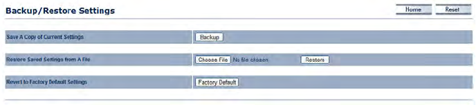
4.5.4 Configuring Backup/Restore Settings
Click the Backup/Restore Setting link under the Management menu to save the ENS200’s current settings in a file on your local disk
or load settings onto the device from a local disk. This feature is particularly convenient administrators who have several ENS200
devices that need to be configured with the same settings.
This page also lets you return the ENS200 to its factory default settings. If you perform this procedure, any changes made to the
ENS200 default settings will be lost.
Save A Copy of Current Settings Click Backup to save the
current configured settings.
Restore Saved Settings from a File To restore settings that
have been previously backed up, click Browse, select the file,
and click Restore.
Revert to Factory Default Settings Click this button to restore
the ENS200 to its factory default settings.

BASIC NETWORK SETTINGS CONFIGURING FIRMWARE UPGRADE
4-49
4.5.5 Configuring Firmware Upgrade
Firmware is system software that operates and allows the administrator to interact with the router.
WARNING!
Upgrading firmware through a wireless connection is not recommended. Firmware upgrading must be performed while connected
to an Ethernet (LAN port) with all other clients disconnected.
The firmware upgrade procedure can take several minutes. Do not power off the ENS200 during the firmware upgrade, as it can cause the
device to crash or become unusable.
To update the firmware version, follow these steps:
1. Download the appropriate firmware approved by EnGe-
nius Networks from an approved web site.
Note:
Save the firmware file to a local hard drive.
2. Click Choose File.
3. Browse the file system and select the firmware file.
4. Click Upload.
5. The ENS200 restarts automatically after the upgrade
completes.
!
BASIC NETWORK SETTINGS CONFIGURING SYSTEM TIME
4-50
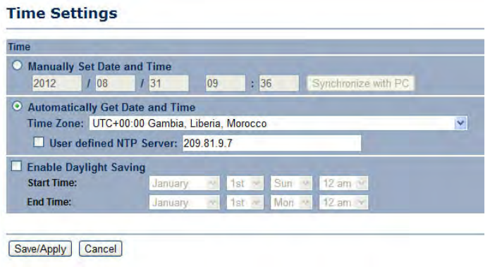
4.5.6 Configuring System Time
Change the system time of the ENS200 and setup automatic updates through a network time (NTP) protocol server or through a PC.
Manually Set Date and Time Manually specify the date and
time.
Synchronize with PC Click this button to get the date and time
settings from the administrator’s PC.
Automatically Get Date and Time Select a time zone from the
drop-down list and check whether you want to enter the IP
address of an NTP server or use the default NTP server.
Click Save/Apply to apply the changes or Cancel to return
previous settings.
BASIC NETWORK SETTINGS CONFIGURING COMMAND LINE INTERFACE
4-51
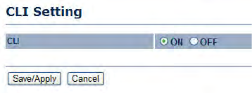
4.5.7 Configuring Command Line Interface
Most users will configure the ENS200 through the graphical user interface (GUI). However, for those who prefer an alternative
method there is the command line interface (CLI). The CLI can be access through a command console, modem or Telnet connec-
tion.
CLI Select to enable or disable the ability to modify the ENS200
via a command line interface (CLI).
Click Save/Apply to apply the changes or Cancel to return
previous settings.
BASIC NETWORK SETTINGS CONFIGURING LOGGING
4-52
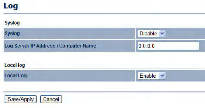
4.5.8 Configuring Logging
Display a list of events that are triggered on the ENS200 Ethernet and wireless interfaces. You can consult this log if an unknown
error occurs on the system or when a report needs to be sent to the technical support department for debugging purposes.
Syslog Enable or disable the ENS200 syslog function.
Log Server IP Address Enter the IP address of the log server.
Local Log Enable or disable the local log service.
Click Save/Apply to apply the changes or Cancel to return
previous settings.
BASIC NETWORK SETTINGS CONFIGURING DIAGNOSTICS
4-53
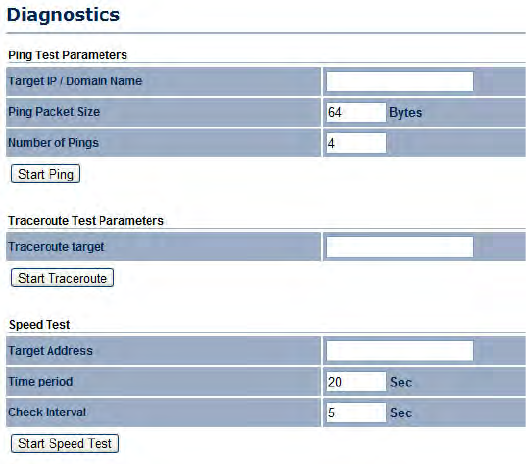
4.5.9 Configuring Diagnostics
The diagnosis feature allow the administrator to verify that another device is available on the network and is accepting request pack-
ets. If the ping result returns alive, it means a device is on line. This feature does not work if the target device is behind a firewall or
has security software installed.
Target IP Enter the IP address you would like to search.
Ping Packet Size Enter the packet size of each ping.
Number of Pings Enter the number of times you want to ping.
Start Ping Click Start Ping to begin pinging.
Trace route Target Enter an IP address or domain name you
want to trace.
Start Trace route Click Start Trace route to begin the trace
route operation.
Target Address Enter the IP address of the target PC.
Time Period Enter time period for the speed test.
Check Interval Enter the interval for the speed test.
Start Speed Test Click Start Speed Test to begin the speed test
operation.

BASIC NETWORK SETTINGS VIEWING DEVICE DISCOVERY
4-54
4.5.10 Viewing Device Discovery
Device Name Displays the name of the devices connected to
the network of the ENS200.
Operation Mode Displays the operation mode of the devices
connected to the network of the ENS200.
IP Address Displays the IP address of the devices connected
to the network of the ENS200.
System MAC Address Displays the system MAC address of
the devices connected to the network of the ENS200.
Firmware Version Displays the firmware version of the devices
connected to the network of the ENS200.
BASIC NETWORK SETTINGS CONFIGURE DENIAL OF SERVICE PROTECTION
4-55
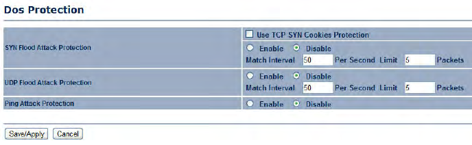
4.5.11 Configure Denial of Service Protection
Use TCP SYN Cookies Protection Click to enable TCP SYN
cookies protection.
SYN Flood Attack Protection Click to enable or disable SYN
Flood Attack Protection.
Match Interval Per Second Enter the allowed number of
packets per second.
Limit Packets Enter the maximum number of packets
allowed per request.
UDP Flood Attack Protection Click to enable or disable UDP
Flood Attack Protection.
Match Interval Per Second Enter the allowed number of
packets per second.
Limit Packets Enter the maximum number of packets
allowed per request.
Ping Attack Protection Click to enable or disable ping attack
protection.
Click Save/Apply to apply the changes or Cancel to return
previous settings.
BASIC NETWORK SETTINGS LOGGING OUT
4-56
4.5 Logging Out
Click Logout to logout from the ENS200.

APPENDIX A FEDERAL COMMUNICATION COMMISSION INTERFERENCE STATEMENT
A-1
Appendix A
Federal Communication Commission Interference
Statement
This equipment has been tested and found to comply with the limits for a Class B digital device, pursuant to Part 15 of the FCC
Rules. These limits are designed to provide reasonable protection against harmful interference in a residential installation. This
equipment generates uses and can radiate radio frequency energy and, if not installed and used in accordance with the instructions,
may cause harmful interference to radio communications. However, there is no guarantee that interference will not occur in a partic-
ular installation. If this equipment does cause harmful interference to radio or television reception, which can be determined by turn-
ing the equipment off and on, the user is encouraged to try to correct the interference by one of the following measures:
Reorient or relocate the receiving antenna.
Increase the separation between the equipment and receiver.
Connect the equipment into an outlet on a circuit different from that to which the receiver is connected.
Consult the dealer or an experienced radio/TV technician for help.
This device complies with Part 15 of the FCC Rules. Operation is subject to the following two conditions: (1) This device may not
cause harmful interference, and (2) this device must accept any interference received, including interference that may cause unde-
sired operation.
FCC Radiation Exposure Statement
WARNING!
Any changes or modifications not expressly approved by the party responsible for compliance could void the user's authority to
operate this equipment.
!

APPENDIX A FEDERAL COMMUNICATION COMMISSION INTERFERENCE STATEMENT
A-2
Important:
This equipment complies with FCC radiation exposure limits set forth for an uncontrolled environment.
This device complies with FCC RF Exposure limits set forth for an uncontrolled environment, under 47 CFR 2.1093 paragraph
(d)(2).
This transmitter must not be co-located or operating in conjunction with any other antenna or transmitter.
Radiation Exposure Statement:
This equipment complies with FCC radiation exposure limits set forth for an uncontrolled environment. This equipment
should be installed and operated with minimum distance 20cm between the radiator & your body

APPENDIX B INDUSTRY CANADA STATEMENT
B-1
Appendix B
Industry Canada Statement
This device complies with RSS-210 of the Industry Canada Rules. Operation is subject to the following two conditions: (1) This
device may not cause harmful interference, and (2) this device must accept any interference received, including interference that
may cause undesired operation.
Ce dispositif est conforme à la norme CNR-210 d'Industrie Canada applicable aux appareils radio exempts de licence. Son fonc-
tionnement est sujet aux deux conditions suivantes: (1) le dispositif ne doit pas produire de brouillage préjudiciable, et (2) ce disposi-
tif doit accepter tout brouillage reçu, y compris un brouillage susceptible de provoquer un fonctionnement indésirable.
Important:
Radiation Exposure Statement:
This equipment complies with IC radiation exposure limits set forth for an uncontrolled environment. This equipment should be
installed and operated with minimum distance 20cm between the radiator & your body.
Déclaration d'exposition aux radiations:
Cet équipement est conforme aux limites d'exposition aux rayonnements IC établies pour un environnement non contrôlé. Cet équipement doit
être installé et utilisé avec un minimum de 20 cm de distance entre la source de rayonnement et votre corps.

APPENDIX C WORLDWIDE TECHNICAL SUPPORT
C-1
Appendix C
WorldWide Technical Support
REGION/COUNTRY OF PURCHASE SERVICE CENTRE SERVICE INFORMATION
Canada
CANADA web site www.engeniuscanada.com
email rma@engeniuscanada.com
contact numbers Toll Free: (+1) 888-397-2788
Local: (+1) 905-940-8181
hours of operation Monday - Friday
9:00AM to 5:30PM EST (GMT-5)
USA
LOS ANGELES, USA web site www.engeniustech.com
email support@engeniustech.com
contact numbers Toll Free: (+1) 888-735-7888
Local: (+1) 714-432-8668
hours of operation Monday - Friday
8:00 AM to 4:30 PM PST (GMT-8)
Mexico, Central and Southern America MIAMI, USA web site [ES] es.engeniustech.com
[PT] pg.engeniustech.com
email miamisupport@engeniustech.com

APPENDIX C WORLDWIDE TECHNICAL SUPPORT
C-2
contact numbers
Miami: (+1) 305-887-7378
Sao Paulo, Brazil: (+55)11-3957-0303
D.F., Mexico:(+52)55-1163-8894
hours of operation Monday - Friday
8:00 AM to 5:30PM EST (GMT-5)
Europe
NETHERLANDS web site www.engeniusnetworks.eu
email support@engeniusnetworks.eu
contact numbers (+31) 40-8200-887
hours of operation Monday - Friday
9:00 AM - 5:00 PM (GMT+1)
Africa
Middle East
Russia
CIS / Armenia, Azerbaijan, Belarus,
Georgia, Kazakhstan, Kyrgyzstan,
Moldova, Tajikistan,
Turkmenistan, Ukraine,
Uzbekistan
Turkey
Afghanistan
Pakistan
Bangladesh, Maldives,
Nepal, Bhutan, Sri Lanka
DUBAI, UAE web site www.engenius-me.com
email support@engenius-me.com
contact numbers
Toll Free:
U.A.E.: 800-EnGenius
800-364-364-87
General:
(+971) 4357-5599
hours of operation Sunday - Thursday
9:00 AM - 6:00 PM (GMT+4)
REGION/COUNTRY OF PURCHASE SERVICE CENTRE SERVICE INFORMATION

APPENDIX C WORLDWIDE TECHNICAL SUPPORT
C-3
Singapore, Cambodia,
Indonesia, Malaysia,
Thailand, Philippines,
Vietnam
China, Hong Kong, Korea
India
South Africa
Oceania
SINGAPORE web site www.engeniustech.com.sg/e_warranty_form
email techsupport@engeniustech.com.sg
contact numbers Toll Free:
Singapore: 1800-364-3648
hours of operation Monday - Friday
9:00 AM - 6:00 PM (GMT+8)
Others TAIWAN, R.O.C. web site www.engeniusnetworks.com
email technology@senao.com
Note:
* Service hours are based on the local time of the service center.
* Please visit the website for the latest information about customer service.
REGION/COUNTRY OF PURCHASE SERVICE CENTRE SERVICE INFORMATION