EnOcean TCM2XXC 315 MHz Transceiver with optional Repeater capability User Manual CERTIFICATE OF COMPLIANCE
EnOcean GmbH 315 MHz Transceiver with optional Repeater capability CERTIFICATE OF COMPLIANCE
UserManual.wiki
>
EnOcean
>
TCM2XXC User Manual
User Manual
Navigation menu
Upload a User Manual
Namespaces
Wiki Guide
HTML
PDF
Info
Views
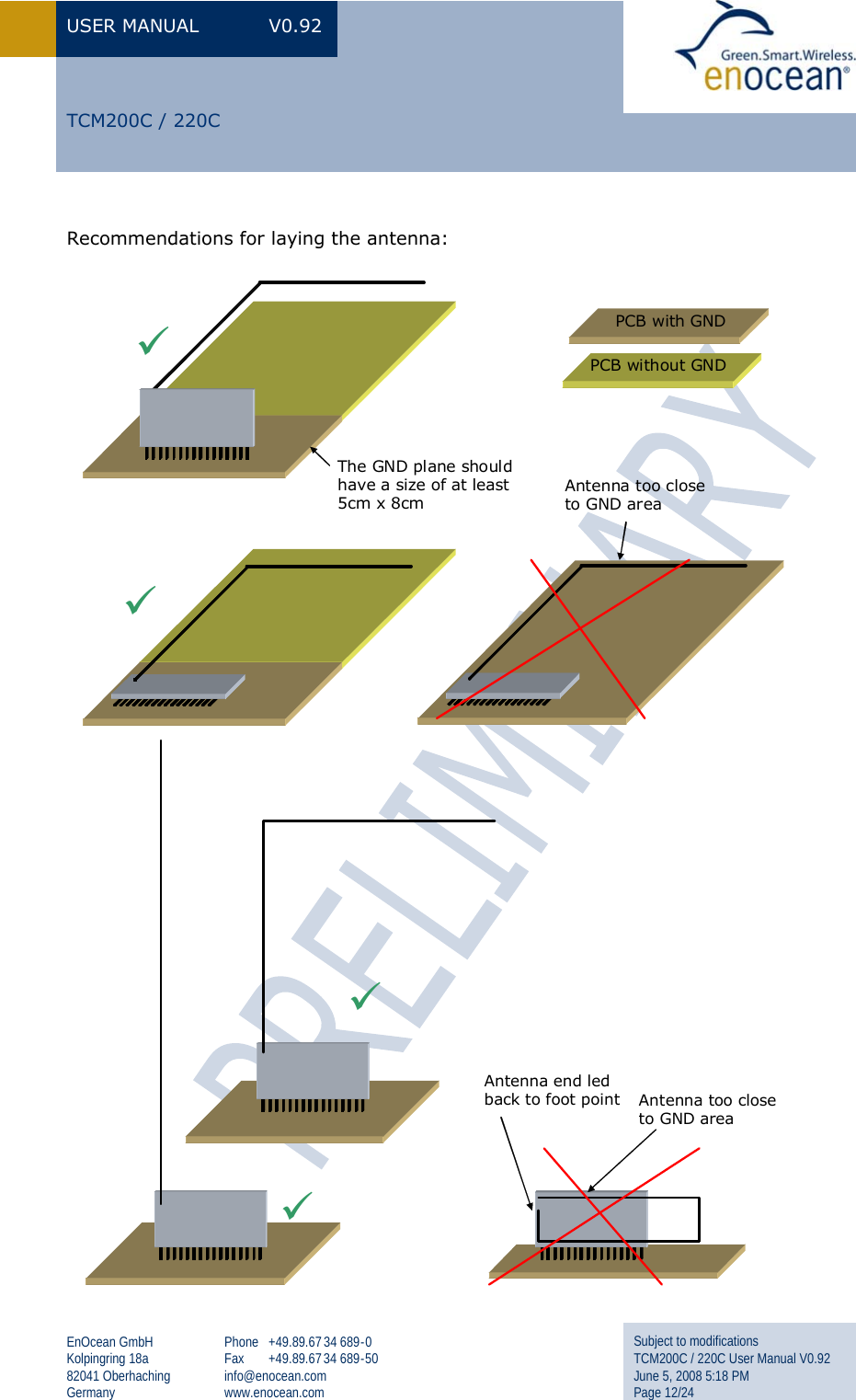
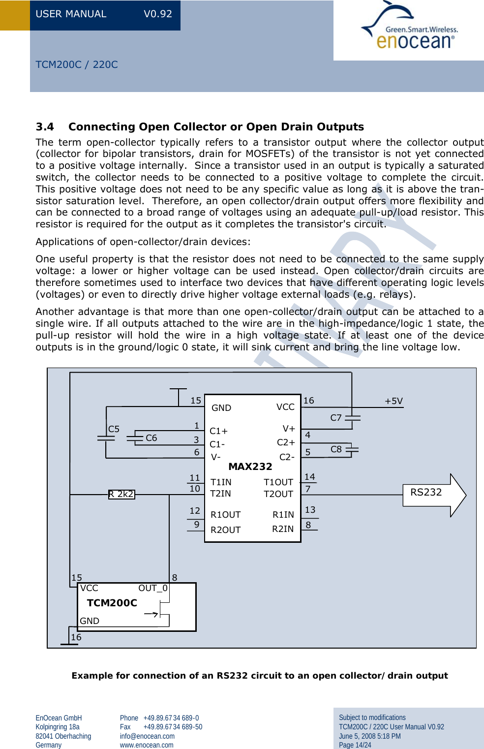
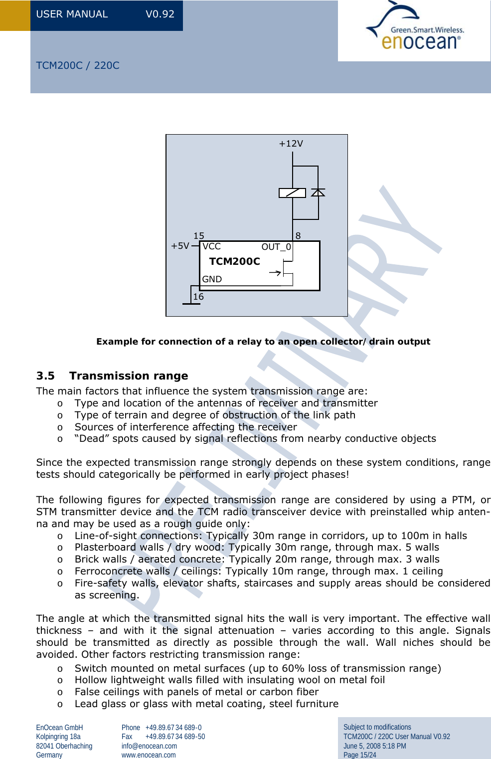
User Manual
Discussion / Help
Navigation