EnOcean TCM2XXC 315 MHz Transceiver with optional Repeater capability User Manual CERTIFICATE OF COMPLIANCE
EnOcean GmbH 315 MHz Transceiver with optional Repeater capability CERTIFICATE OF COMPLIANCE
EnOcean >
User Manual

Rhein Tech Laboratories, Inc. Client: EnOcean GmbH
360 Herndon Parkway Models: TCM200C & TCM220C
Suite 1400 Standards: FCC 15.231/IC RSS-210
ID’s: SZV-TCM2XXC/5713A-TCM2XXC Herndon, VA 20170
http://www.rheintech.com Report #: 2008102
Page 26 of 30
Appendix K: Manual
Please see the following pages.

USER MANUAL V0.92
EnOcean GmbH
Kolpingring 18a
82041 Oberhaching
Germany
Phone +49.89.67 34 689-0
Fax +49.89.67 34 689-50
info@enocean.com
www.enocean.com
Subject to modifications
TCM200C / 220C User Manual V0.92
June 5, 2008 5:18 PM
Page 1/24
Patent protected:
WO98/36395, DE 100 25 561, DE 101 50 128,
WO 2004/051591, DE 103 01 678 A1, DE 10309334,
WO 04/109236, WO 05/096482, WO 02/095707,
US 6,747,573, US 7,019,241
Transceiver Module
TCM200C / 220C
June 5, 2008
PRELIMINARY

USER MANUAL V0.92
EnOcean GmbH
Kolpingring 18a
82041 Oberhaching
Germany
Phone +49.89.67 34 689-0
Fax +49.89.67 34 689-50
info@enocean.com
www.enocean.com
Subject to modifications
TCM200C / 220C User Manual V0.92
June 5, 2008 5:18 PM
Page 2/24
TCM200C / 220C
REVISION HISTORY
The following major modifications and improvements have been made to the first version of
this document:
No Major Changes
0.92 Corrected: No internal pull-up on IN_5
0.93 Agency Certification section added
Published by EnOcean GmbH, Kolpingring 18a, 82041 Oberhaching, Germany
www.enocean.com, info@enocean.com, phone ++49 (89) 6734 6890
© EnOcean GmbH
All Rights Reserved
Important!
This information describes the type of component and shall not be considered as assured
characteristics. No responsibility is assumed for possible omissions or inaccuracies. Circuitry
and specifications are subject to change without notice. For the latest product specifica-
tions, refer to the EnOcean website: http://www.enocean.com.
As far as patents or other rights of third parties are concerned, liability is only assumed for
modules, not for the described applications, processes and circuits.
EnOcean does not assume responsibility for use of modules described and limits its liability
to the replacement of modules determined to be defective due to workmanship. Devices or
systems containing RF components must meet the essential requirements of the local legal
authorities.
The modules must not be used in any relation with equipment that supports, directly or
indirectly, human health or life or with applications that can result in danger for people,
animals or real value.
Components of the modules are considered and should be disposed of as hazardous waste.
Local government regulations are to be observed.
Packing: Please use the recycling operators known to you. By agreement we will take pack-
ing material back if it is sorted. You must bear the costs of transport. For packing material
that is returned to us unsorted or that we are not obliged to accept, we shall have to in-
voice you for any costs incurred.

USER MANUAL V0.92
EnOcean GmbH
Kolpingring 18a
82041 Oberhaching
Germany
Phone +49.89.67 34 689-0
Fax +49.89.67 34 689-50
info@enocean.com
www.enocean.com
Subject to modifications
TCM200C / 220C User Manual V0.92
June 5, 2008 5:18 PM
Page 3/24
TCM200C / 220C
TABLE OF CONTENT
1 GENERAL DESCRIPTION ............................................................................... 4
1.1 Basic Functionality ....................................................................................... 4
1.2 Technical Data ............................................................................................ 4
1.3 Physical Dimensions .................................................................................... 5
1.4 Environmental Conditions ............................................................................. 5
1.5 Ordering Information ................................................................................... 5
2 FUNCTIONAL DESCRIPTION .......................................................................... 6
2.1 Block Diagram ............................................................................................ 6
2.2 Pin Description and operational characteristics ................................................. 7
2.3 Absolute maximum ratings ........................................................................... 8
2.4 Equivalent schematics .................................................................................. 9
2.4.1 Open drain outputs OUT_0..3 (TCM200C only) ............................................. 9
2.5 Transmit timing (only in repeater mode) ......................................................... 9
3 APPLICATIONS INFORMATION ...................................................................... 10
3.1 Transmission range .................................................................................... 10
3.2 Mounting the antenna ................................................................................. 11
3.2.1 Mounting the 15cm whip antenna ............................................................. 11
3.2.2 Mounting 50Ω antennas ........................................................................... 13
3.3 Power supply requirements .......................................................................... 13
3.4 Connecting Open Collector or Open Drain Outputs ........................................... 14
3.5 Transmission range .................................................................................... 15
3.6 FCC/IC approval requirements ............................ Error! Bookmark not defined.
4 DEVELOPMENT TOOLS ................................................................................ 19
APPENDIX ............................................................................................................. 20
A.1 EnOcean serial protocol ............................................................................... 20
A.1.1 Message format ...................................................................................... 20
A.1.2 Octet signals and bit order ....................................................................... 20
A.1.3 Description of serial data structure ............................................................ 21
A.1.4 Detailed description of ORG field ............................................................... 21
A.1.5 Detailed description of STATUS field .......................................................... 22
A.1.6 Detailed description of DATA_BYTE 3..0 fields ............................................. 23
USER MANUAL V0.92
EnOcean GmbH
Kolpingring 18a
82041 Oberhaching
Germany
Phone +49.89.67 34 689-0
Fax +49.89.67 34 689-50
info@enocean.com
www.enocean.com
Subject to modifications
TCM200C / 220C User Manual V0.92
June 5, 2008 5:18 PM
Page 4/24
TCM200C / 220C
1 GENERAL DESCRIPTION
1.1 Basic Functionality
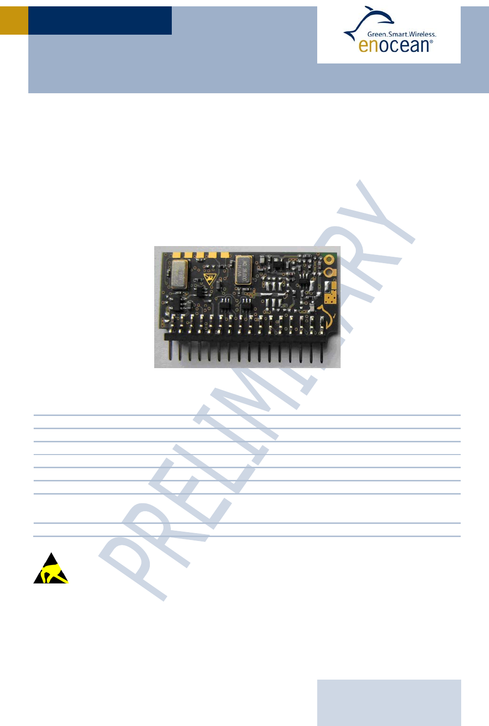
The transceiver modules TCM 200C and TCM 220C of EnOcean enable the realization of
highly efficient RF repeaters and transceivers for the EnOcean 315 MHz radio system. The
module receives all signals of the EnOcean radio transmitters and makes them available at
the serial port. In addition a repeater functionality can be activated. Using API200 it is pos-
sible to write custom software for the module.
TCM200C / TCM220C without antenna
1.2 Technical Data
Antenna 15cm whip antenna installed, external 50Ω antenna mountable
Frequency 315.0 MHz
Data rate / Modulation type 125 kbps / ASK
Conducted output power typ. 5dBm
Receiver sensitivity typ. –95 dBm
Power supply voltage TCM200C: 5V ±5%, TCM220C 3V ±5%
Power supply current Receive mode: typ. 29mA, max. 34mA (RX)
Transmit mode: max. 40mA (TX)
Radio standards approvable according to FCC / IC for use in North America
Observe precautions! Electrostatic sensitive devices!
USER MANUAL V0.92
EnOcean GmbH
Kolpingring 18a
82041 Oberhaching
Germany
Phone +49.89.67 34 689-0
Fax +49.89.67 34 689-50
info@enocean.com
www.enocean.com
Subject to modifications
TCM200C / 220C User Manual V0.92
June 5, 2008 5:18 PM
Page 5/24
TCM200C / 220C
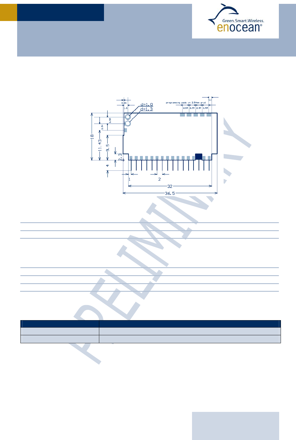
1.3 Physical Dimensions
PCB dimensions (without pin connector) 18.0 x 36.5 mm
Pin connector 16 pins, grid 2.0 mm (4.0 mm in length, 0.5 mm)
1.4 Environmental Conditions
Operating temperature -25°C … +65 °C
Storage temperature -40°C up … +85 °C
Humidity 0% … 95% r.h.
1.5 Ordering Information
Type Ordering Code
TCM200C S3033-K200
TCM220C S3033-K220
GND
IN_0
IN_1
IN_2
IN_3
IN_4
IN_5
OUT_0
OUT_1
OUT_2
OUT_3
OUT_4
RXD
n.c.
VCC
GND
ANT1
ANT2
PP1
PP2
PP3
PP4
PP5
TCM200C/TCM220C Dimensions (mm)
GND
USER MANUAL V0.92
EnOcean GmbH
Kolpingring 18a
82041 Oberhaching
Germany
Phone +49.89.67 34 689-0
Fax +49.89.67 34 689-50
info@enocean.com
www.enocean.com
Subject to modifications
TCM200C / 220C User Manual V0.92
June 5, 2008 5:18 PM
Page 6/24
TCM200C / 220C
2 FUNCTIONAL DESCRIPTION
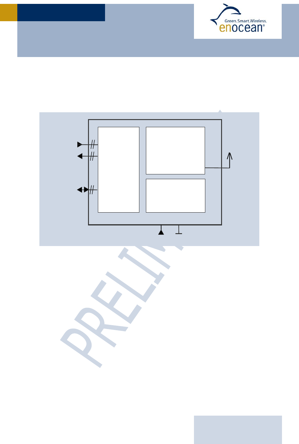
2.1 Block Diagram
VCC
µC
GNDVCC
IN_0..5
OUT_0..4
ANT
RF
Transceiver
Voltage
regulator
(TCM200C only)
PP1..5
VCC
µC
GNDVCC
IN_0..5
OUT_0..4
ANT
RF
Transceiver
Voltage
regulator
(TCM200C only)
PP1..5

USER MANUAL V0.92
EnOcean GmbH
Kolpingring 18a
82041 Oberhaching
Germany
Phone +49.89.67 34 689-0
Fax +49.89.67 34 689-50
info@enocean.com
www.enocean.com
Subject to modifications
TCM200C / 220C User Manual V0.92
June 5, 2008 5:18 PM
Page 7/24
TCM200C / 220C
2.2 Pin Description and operational characteristics
Pin Symbol Function TCM200C Function TCM220C
1 GND Ground connection
2
3
4
5
6
IN_0
IN_1
IN_2
IN_3
IN_4
Digital inputs 3V logic, 5V
tolerant, internal pull-up (3V)
Digital inputs, 3V logic
or analog inputs 3V
7 IN_5 Digital input, 3V logic, 5V
tolerant
Digital input, 3V logic
8
9
10
11
OUT_0
OUT_1
OUT_2
OUT_3
Open drain output,
35 V max., 100 mA max.,
100 mW max. each.
Digital output, 3V logic, 20mA max.
12 OUT_4 Digital output, 5V logic,
20mA max.
Digital output, 3V logic, 20mA max.
13 RXD For EnOcean internal use only
14 n.c. Not used
15 VCC Power supply 5V
±
5% Power supply 3V
±
5%
16 GND Ground connection
ANT1 Foot point for whip antenna
ANT2 Foot point for 50
Ω
antenna
PP1 ICSP_VPP Programming voltage or active low reset to controller
PP2 Vcc 3V internal VCC for programming interface
PP3 GND Ground connection for programming interface
PP4 ICSP_DATA In-circuit debugger and ICSP programming data
PP5 ICSP_CLK In-circuit debugger and ICSP programming clock
The module provides a basic firmware which is flashed at time of production.
It provides the following features:
Serial output of received EnOcean radio telegrams at OUT_0 (see appendix A.1)
Repeater activation if IN_2 LOW at startup
The receiver sensitivity can be controlled via IN_3:
Reduced sensitivity if IN_3 LOW, high sensitivity if IN_3 HIGH
Please use external pull-ups at the IN_2 and IN_3 of TCM220C to assure defined
input levels!
In addition EnOcean provides an API (please refer to API200 User Manual) which allows to
write customer specific firmware for the microcontroller of the module.

USER MANUAL V0.92
EnOcean GmbH
Kolpingring 18a
82041 Oberhaching
Germany
Phone +49.89.67 34 689-0
Fax +49.89.67 34 689-50
info@enocean.com
www.enocean.com
Subject to modifications
TCM200C / 220C User Manual V0.92
June 5, 2008 5:18 PM
Page 8/24
TCM200C / 220C
2.3 Absolute maximum ratings
Symbol Description Parameter TCM200C TCM220C Units
min. max. min. max.
VCC Supply Voltage (Note 1) VCC -0.3 5.5 -0.3 3.6 V
OUT_0 Output 0 (Note 2) Voltage -0.3 60 -0.3 VCC+0.3
V
Current 200 ± 25 mA
OUT_1..3 Output 1..3 (Note 2) Voltage -0.3 60 -0.3 6 V
Output source or sink current Current ± 25 mA
Max. load current Current 200 mA
OUT_4 Output 4 (Note 3) Voltage -0.3 6 V
Output diode current
Vout < -0.5 V or Vout > VCC +
0.5 V
Current ± 20 mA
Output source or sink current Current ± 25 ± 25 mA
IN_0..4 Input 0..4 Voltage -0.3 6 -0.3 VCC+0.3
V
IN_5 Input 5 (SER_RX) Voltage -0.3 6 -0.3 6 V
RXD For EnOcean internal use only! this pin has to be left open for proper function of the device
VCCi Internal Voltage (Note 1) Voltage not allowed see VCC V
Vpp Programming Voltage Voltage -0.3 6 -0.3 6 V
ICSP_DATA Programming Data Voltage -0.3 6 -0.3 6 V
ICSP_CLK Programming Clock Voltage -0.3 6 -0.3 6 V
ANT2 50 Ohm Antenna (Note 4) Voltage 0 0 V
RF power -7 -7 dBm
ANT1 Whip Antenna (Note 4) Voltage 0 0 V
Note 1: on TCM200C VCCi is the internal stabilized voltage of 3V (should not be used for driving external circuitry)
on TCM220C VCCi is VCC
Note 2: on TCM200C OUT_0..3 are Open-Drain-Outputs, max. power dissipation 300mW for OUT_0/1 and OUT_2/3 each
(dual transistor)
on TCM220C Output 0..3 are digital outputs at 3V (Low: max. 0.4V, High: min. 2.4V, see datasheet PIC18F65J11)
Note 3: on TCM200C OUT_4 is an digital driver output at 5V
on TCM220C OUT_4 is an digital output at 3V (Low: max. 0.4V, High: min. 2.4V, see datasheet PIC18F65J11)
Note 4: antenna connections are DC-shorted to ground, only for RF signal, no DC voltage should be applied
USER MANUAL V0.92
EnOcean GmbH
Kolpingring 18a
82041 Oberhaching
Germany
Phone +49.89.67 34 689-0
Fax +49.89.67 34 689-50
info@enocean.com
www.enocean.com
Subject to modifications
TCM200C / 220C User Manual V0.92
June 5, 2008 5:18 PM
Page 9/24
TCM200C / 220C
2.4 Equivalent schematics
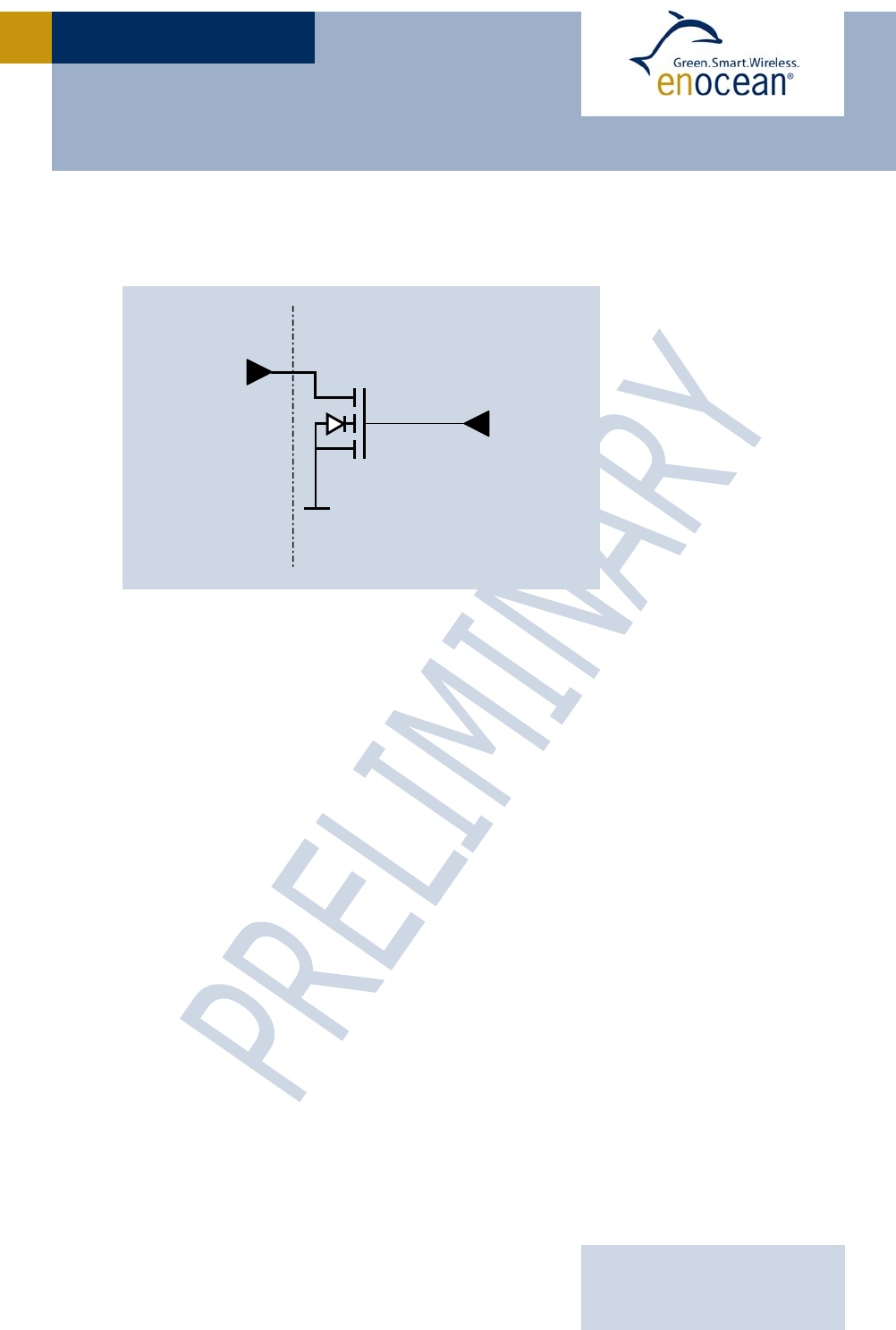
2.4.1 Open drain outputs OUT_0..3 (TCM200C only)
2.5 Transmit timing (only in repeater mode)
The setup of the transmission timing allows avoiding possible collisions with data packages
of other EnOcean transmitters as well as disturbances from the environment. With each
transmission cycle, 3 identical subtelegrams are transmitted. The transmission of a sub-
telegram lasts approximately 1.2 ms. To optimize data security, each telegram is repeated
twice within about 40 ms, whereas the delay between the three transmission bursts is ef-
fected at random.
Delay between received telegam and 1st subtelegram: 1 ms + n x 1 ms (integer n: 0≤n≤3)
Delay between 1st and 2nd subtelegram: 6 ms + n x 1 ms (integer n: 0≤n≤3)
Delay between 2nd and 3rd subtelegram: 18 ms + n x 1 ms (integer n: 0≤n≤11)
OUT_x
external
(OD) OUT_x
internal
(TTL)

USER MANUAL V0.92
EnOcean GmbH
Kolpingring 18a
82041 Oberhaching
Germany
Phone +49.89.67 34 689-0
Fax +49.89.67 34 689-50
info@enocean.com
www.enocean.com
Subject to modifications
TCM200C / 220C User Manual V0.92
June 5, 2008 5:18 PM
Page 10/24
TCM200C / 220C
3 APPLICATIONS INFORMATION
3.1 Transmission range
The main factors that influence the system transmission range are type and location of the
antennas of the receiver and the transmitter, type of terrain and degree of obstruction of
the link path, sources of interference affecting the receiver, and “Dead” spots caused by
signal reflections from nearby conductive objects. Since the expected transmission range
strongly depends on this system conditions, range tests should categorically be performed
before notification of a particular range that will be attainable by a certain application.
The following figures for expected transmission range are considered by using a PTM, a
STM or a TCM radio transmitter device and the TCM radio receiver device with preinstalled
whip antenna and may be used as a rough guide only:
Line-of-sight connections: Typically 30m range in corridors, up to 100m in halls
Plasterboard walls / dry wood: Typically 30m range, through max. 5 walls
Line-of-sight connections: Typically 30m range in corridors, up to 100m in halls
Ferroconcrete walls / ceilings: Typically 10m range, through max. 1 ceiling
Fire-safety walls, elevator shafts, staircases and supply areas should be considered as
screening.
The angle at which the transmitted signal hits the wall is very important. The effective wall
thickness – and with it the signal attenuation – varies according to this angle. Signals
should be transmitted as directly as possible through the wall. Wall niches should be
avoided. Other factors restricting transmission range:
Switch mounted on metal surfaces (up to 30% loss of transmission range)
Hollow lightweight walls filled with insulating wool on metal foil
False ceilings with panels of metal or carbon fiber
Lead glass or glass with metal coating, steel furniture
The distance between EnOcean receivers and other transmitting devices such as comput-
ers, audio and video equipment that also emit high-frequency signals should be at least
0.5m
A summarized application note to determine the transmission range within buildings is
available as download from www.enocean.com.
USER MANUAL V0.92
EnOcean GmbH
Kolpingring 18a
82041 Oberhaching
Germany
Phone +49.89.67 34 689-0
Fax +49.89.67 34 689-50
info@enocean.com
www.enocean.com
Subject to modifications
TCM200C / 220C User Manual V0.92
June 5, 2008 5:18 PM
Page 11/24
TCM200C / 220C
3.2 Mounting the antenna
Positioning and choice of receiver and transmitter antennas are the most important factors
in determining system transmission range.
TCM200C and TCM220C are providing two antenna outputs, ANT1 and ANT2:
ANT1 is designed for use with a 15cm whip antenna
ANT2 is designed for use with 50Ω antennas, e.g. helix antenna or external antenna
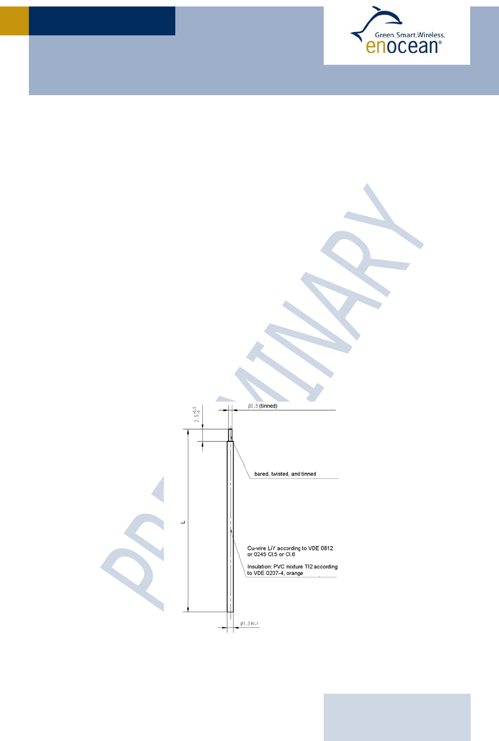
3.2.1 Mounting the 15cm whip antenna
For good receiver performance, great care must be taken about the space immediately
around the antenna since this has a strong influence on screening and detuning the anten-
na. The antenna should be drawn out as far as possible and must never be cut off. Mainly
the far end of the wire should be mounted as far away as possible (at least 15 mm) from all
metal parts, ground planes, PCB strip lines and fast logic components (e.g. microproces-
sors).
Do not roll up or twist the whip antenna!
Radio frequency hash from the motherboard desensitizes the receiver. Therefore:
PCB strip lines on the user board should be designed as short as possible
A PCB ground plane layer with sufficient ground vias is strongly recommended
See also section 3.3 for power supply requirements. Problems may especially occur with
switching power supplies!
Specification of the TCM whip antenna; L=150mm
USER MANUAL V0.92
EnOcean GmbH
Kolpingring 18a
82041 Oberhaching
Germany
Phone +49.89.67 34 689-0
Fax +49.89.67 34 689-50
info@enocean.com
www.enocean.com
Subject to modifications
TCM200C / 220C User Manual V0.92
June 5, 2008 5:18 PM
Page 12/24
TCM200C / 220C
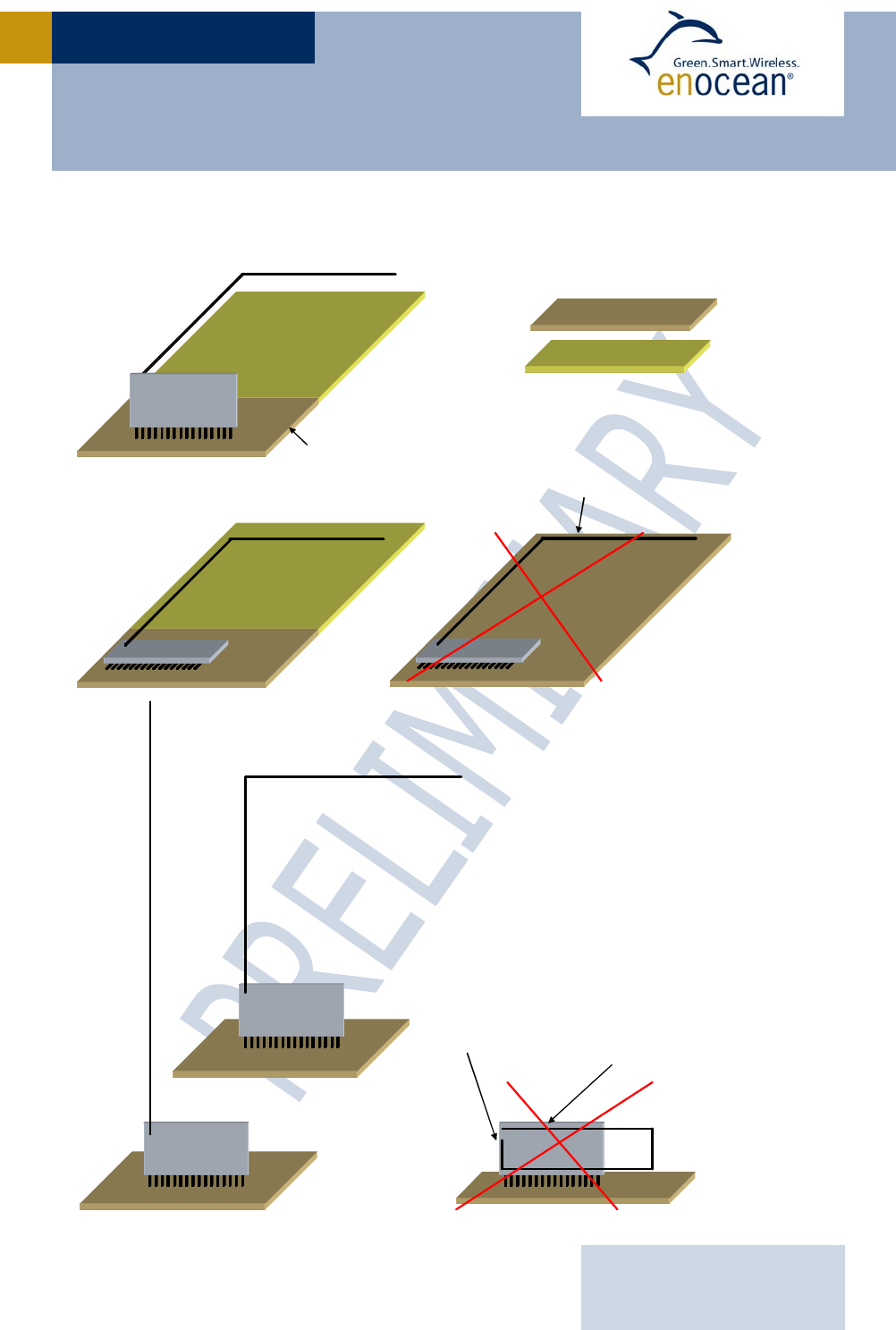
Recommendations for laying the antenna:
9
9
Antenna too close
to GND area
Antenna end led
back to foot point
9PCB with GND
PCB without GND
Antenna too close
to GND area
9
The GND plane should
have a size of at least
5cm x 8cm

USER MANUAL V0.92
EnOcean GmbH
Kolpingring 18a
82041 Oberhaching
Germany
Phone +49.89.67 34 689-0
Fax +49.89.67 34 689-50
info@enocean.com
www.enocean.com
Subject to modifications
TCM200C / 220C User Manual V0.92
June 5, 2008 5:18 PM
Page 13/24
TCM200C / 220C
3.2.2 Mounting 50Ω antennas
For mounting the receiver at bad RF locations (e.g. within a metal cabinet), an external
antenna has to be used.
Unsolder the whip antenna (if already mounted)
Connect external antenna to the module by 50Ω coax cable with Teflon insulation
Connect the inner cable to the ANT2 antenna hole on the PCB
Solder the shielding as short as possible to the antenna GND pad
(length of insulation max. 4 mm)
It is also possible to mount other 50Ω antennas – such as off the shelf helix antennas –
onto the module. In this case the GND pad is not used.
3.3 Power supply requirements
In order to provide a good radio performance, great attention must be paid to the power
supply and a correct layout and shielding. A star-connected topology and at least a 22uF
low-ESR tantalum or similar ceramic capacitor is recommended. This capacitor must be
located as close as possible to the module, between the module supply pin VCC and GND.
Furthermore, a low DC-resistance (<1Ω) EMI-suppressor is needed in series between the
board supply pin input and the output of the power supply rail. We recommend a ferrit
bead e.g. multi layer suppressor type MLS0805-4S7-102 from Ferroxcube.
The ripple on the power supply rail must be below 10 mVpp.
USER MANUAL V0.92
EnOcean GmbH
Kolpingring 18a
82041 Oberhaching
Germany
Phone +49.89.67 34 689-0
Fax +49.89.67 34 689-50
info@enocean.com
www.enocean.com
Subject to modifications
TCM200C / 220C User Manual V0.92
June 5, 2008 5:18 PM
Page 14/24
TCM200C / 220C
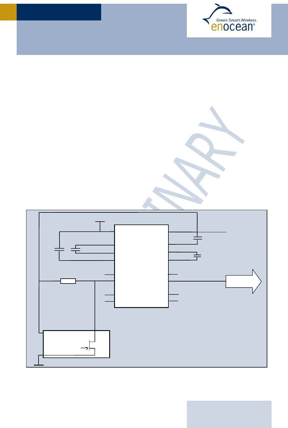
3.4 Connecting Open Collector or Open Drain Outputs
The term open-collector typically refers to a transistor output where the collector output
(collector for bipolar transistors, drain for MOSFETs) of the transistor is not yet connected
to a positive voltage internally. Since a transistor used in an output is typically a saturated
switch, the collector needs to be connected to a positive voltage to complete the circuit.
This positive voltage does not need to be any specific value as long as it is above the tran-
sistor saturation level. Therefore, an open collector/drain output offers more flexibility and
can be connected to a broad range of voltages using an adequate pull-up/load resistor. This
resistor is required for the output as it completes the transistor's circuit.
Applications of open-collector/drain devices:
One useful property is that the resistor does not need to be connected to the same supply
voltage: a lower or higher voltage can be used instead. Open collector/drain circuits are
therefore sometimes used to interface two devices that have different operating logic levels
(voltages) or even to directly drive higher voltage external loads (e.g. relays).
Another advantage is that more than one open-collector/drain output can be attached to a
single wire. If all outputs attached to the wire are in the high-impedance/logic 1 state, the
pull-up resistor will hold the wire in a high voltage state. If at least one of the device
outputs is in the ground/logic 0 state, it will sink current and bring the line voltage low.
Example for connection of an RS232 circuit to an open collector/drain output
TCM200C
8
OUT_0
15
VCC
GND
C1+
C1-
T
1IN
R1OUT
R2OUT
R1IN
R2IN
T
1OUT
T
2IN
T
2OUT
C2+
C2-
V+
VCC
MAX232
15
1
3
6
9
16
4
5
8
7
14
C5
C6
C7
C8
V-
GND
RS232
11
10
13
12
R 2k2
16
+5V
USER MANUAL V0.92
EnOcean GmbH
Kolpingring 18a
82041 Oberhaching
Germany
Phone +49.89.67 34 689-0
Fax +49.89.67 34 689-50
info@enocean.com
www.enocean.com
Subject to modifications
TCM200C / 220C User Manual V0.92
June 5, 2008 5:18 PM
Page 15/24
TCM200C / 220C
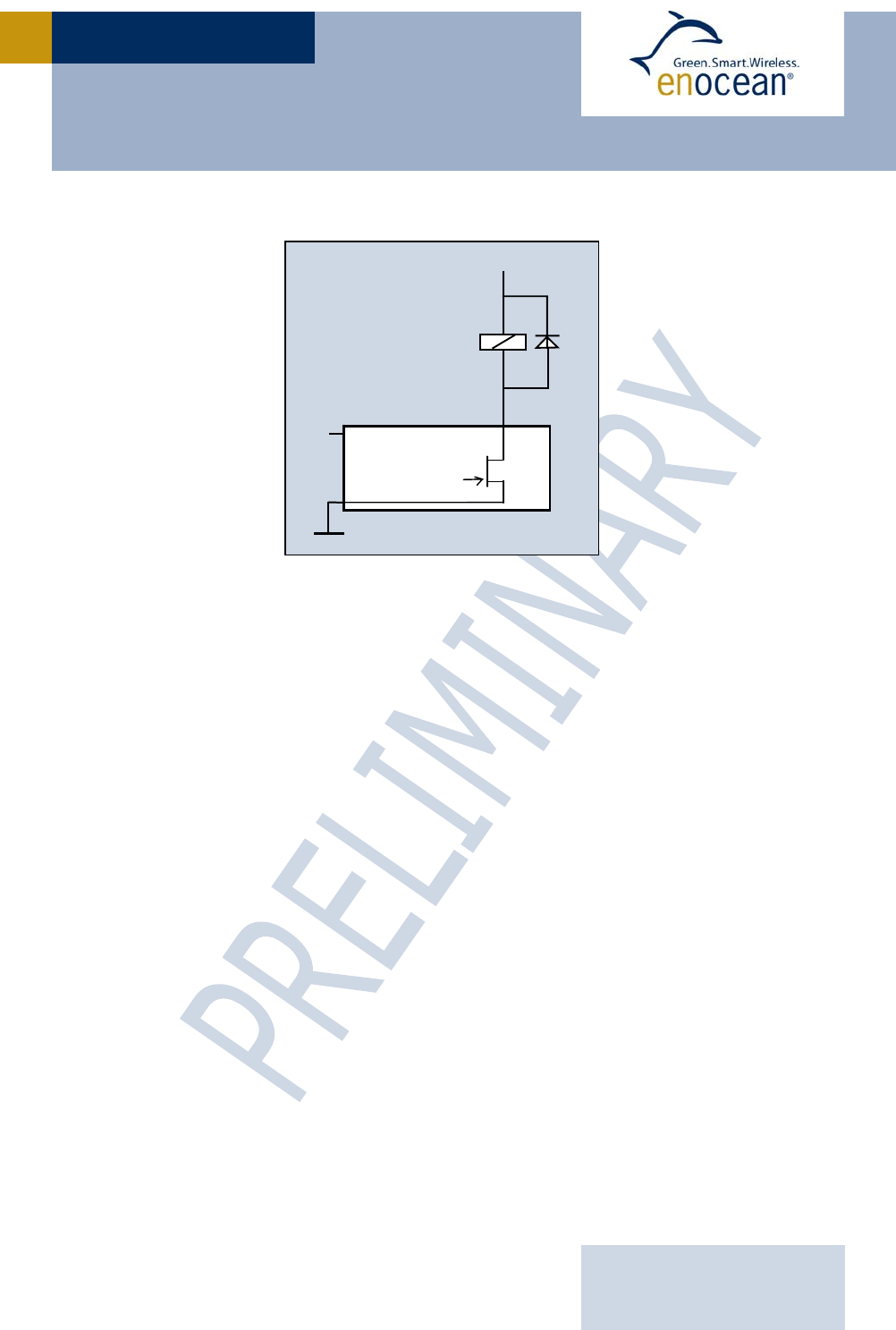
Example for connection of a relay to an open collector/drain output
3.5 Transmission range
The main factors that influence the system transmission range are:
o Type and location of the antennas of receiver and transmitter
o Type of terrain and degree of obstruction of the link path
o Sources of interference affecting the receiver
o “Dead” spots caused by signal reflections from nearby conductive objects
Since the expected transmission range strongly depends on these system conditions, range
tests should categorically be performed in early project phases!
The following figures for expected transmission range are considered by using a PTM, or
STM transmitter device and the TCM radio transceiver device with preinstalled whip anten-
na and may be used as a rough guide only:
o Line-of-sight connections: Typically 30m range in corridors, up to 100m in halls
o Plasterboard walls / dry wood: Typically 30m range, through max. 5 walls
o Brick walls / aerated concrete: Typically 20m range, through max. 3 walls
o Ferroconcrete walls / ceilings: Typically 10m range, through max. 1 ceiling
o Fire-safety walls, elevator shafts, staircases and supply areas should be considered
as screening.
The angle at which the transmitted signal hits the wall is very important. The effective wall
thickness – and with it the signal attenuation – varies according to this angle. Signals
should be transmitted as directly as possible through the wall. Wall niches should be
avoided. Other factors restricting transmission range:
o Switch mounted on metal surfaces (up to 60% loss of transmission range)
o Hollow lightweight walls filled with insulating wool on metal foil
o False ceilings with panels of metal or carbon fiber
o Lead glass or glass with metal coating, steel furniture
TCM200C
8
OUT_0
15
VCC
GND
16
+5V
+12V

USER MANUAL V0.92
EnOcean GmbH
Kolpingring 18a
82041 Oberhaching
Germany
Phone +49.89.67 34 689-0
Fax +49.89.67 34 689-50
info@enocean.com
www.enocean.com
Subject to modifications
TCM200C / 220C User Manual V0.92
June 5, 2008 5:18 PM
Page 16/24
TCM200C / 220C
The distance between EnOcean receivers and other transmitting devices such as comput-
ers, audio and video equipment that also emit high-frequency signals should be at least
1m.
A summarized application note to determine the transmission range within buildings is
available as download from www.enocean.com.

USER MANUAL V0.92
EnOcean GmbH
Kolpingring 18a
82041 Oberhaching
Germany
Phone +49.89.67 34 689-0
Fax +49.89.67 34 689-50
info@enocean.com
www.enocean.com
Subject to modifications
TCM200C / 220C User Manual V0.92
June 5, 2008 5:18 PM
Page 17/24
TCM200C / 220C
3.6 AGENCY CERTIFICATIONS
3.6.1 FCC (United States) Certification
TCM200C and TCM220C LIMITED MODULAR APPROVAL
This is an RF module approved for Limited Modular use operating as an intentional trans-
mitting device with respect to 47 CFR 15.231(a-c) and is limited to OEM installation. The
module is optimized to operate using small amounts of energy, and may be powered by a
battery. The module transmits short radio packets comprised of control signals, (in some
cases the control signal may be accompanied with data) such as those used with alarm sys-
tems, door openers, remote switches, and the like. The module does not support conti-
nuous streaming of voice, video, or any other forms of streaming data; it sends only short
packets containing control signals and possibly data. The module is designed to comply
with, has been tested according to 15.231(a-c), and has been found to comply with each
requirement. Thus, a finished device containing the TCM200C/TCM220C radio module can
be operated in the United States without additional Part 15 FCC approval (approval(s) for
unintentional radiators may be required for the OEM’s finished product), under EnOcean’s
FCC ID number. This greatly simplifies and shortens the design cycle and development
costs for OEM integrators. The module can be triggered manually or automatically, which
cases are described below.
Manual Activation
The radio module can be configured to transmit a short packetized control signal if trig-
gered manually. The module can be triggered, by pressing a switch, for example.
The packet contains one (or more) control signals that is(are) intended to control some-
thing at the receiving end. The packet may also contain data. Depending on how much
energy is available from the energy source, subsequent manual triggers can initiate the
transmission of additional control signals. This may be necessary if prior packet(s)
was(were) lost to fading or interference. Subsequent triggers can also be initiated as a pre-
caution if any doubt exists that the first packet didn’t arrive at the receiver. Each packet
that is transmitted, regardless of whether it was the first one or a subsequent one, will only
be transmitted if enough energy is available from the energy source.
Automatic Activation
The radio module also can be configured to transmit a short packetized control signal
if triggered automatically, by a relevant change of its inputs or in response to receiving a
signal from another transmitter, for example. Again, the packet contains a control signal
that is intended to control something at the receiving end and may also contain data. As
above, it is possible for the packet to get lost and never reach the receiver. However, if
enough energy is available from the energy source, and the module has been configured to
do so, then another packet or packets containing the control signal may be transmitted at a
later time.
The device is designed to operate as a repeater, which can receive signals from the follow-
ing list of FCC/IC approved transmitters, and retransmit the signals.
PTM200C FCC ID:SZV-PTM200C, IC:5731A-PTM-200C
STM110C FCC ID:SZV-STM110C, IC:5731A-STM-110C
TCM200C FCC ID:SZV-TCM-2XXC, IC:5731A-TCM-2XXC
TCM200C FCC ID:SZV-TCM-2XXC, IC:5731A-TCM-2XXC

USER MANUAL V0.92
EnOcean GmbH
Kolpingring 18a
82041 Oberhaching
Germany
Phone +49.89.67 34 689-0
Fax +49.89.67 34 689-50
info@enocean.com
www.enocean.com
Subject to modifications
TCM200C / 220C User Manual V0.92
June 5, 2008 5:18 PM
Page 18/24
TCM200C / 220C
OEM Requirements
In order to use EnOcean’s FCC ID number, the OEM must ensure that the following condi-
tions are met:
End users of products, which contain the module must not have the ability to alter the
firmware that governs the operation of the module. The agency grant is valid only when
the module is incorporated into a final product by OEM integrators.
The end-user must not be provided with instructions to remove, adjust or install the
module.
The Original Equipment Manufacturer (OEM) must ensure that FCC labeling require-
ments are met. This includes a clearly visible label on the outside of the final product.
Attaching a label to a removable portion of the final product, such as a battery cover, is
not permitted. The label must include the following text:
Contains FCC ID: SZV-TCM2XXC
The enclosed device complies with Part 15 of the FCC Rules. Operation is
subject to the following two conditions: (i.) this device may not cause
harmful interference and (ii.) this device must accept any interference re-
ceived, including interference that may cause undesired operation.
The user manual for the end product must also contain the text given above.
Changes or modifications not expressly approved by EnOcean could void the user's au-
thority to operate the equipment.
The module must be used with only the following approved antenna(s).
The OEM must sign the OEM Limited Modular Approval Agreement with EnOcean
3.6.2 IC (Industry Canada) Certification
Labeling requirements for Industry Canada are similar to those required by the FCC. The
Original Equipment Manufacturer (OEM) must ensure that IC labeling requirements are
met. A clearly visible label on the outside of a non-removable part of the final product must
include the following text:
Contains IC: 5731A-TCM2XXC
Part Number Type Gain
N.A. Integrated Wire/Monopole 1.0 dBi

USER MANUAL V0.92
EnOcean GmbH
Kolpingring 18a
82041 Oberhaching
Germany
Phone +49.89.67 34 689-0
Fax +49.89.67 34 689-50
info@enocean.com
www.enocean.com
Subject to modifications
TCM200C / 220C User Manual V0.92
June 5, 2008 5:18 PM
Page 19/24
TCM200C / 220C
4 DEVELOPMENT TOOLS
USER MANUAL V0.92
EnOcean GmbH
Kolpingring 18a
82041 Oberhaching
Germany
Phone +49.89.67 34 689-0
Fax +49.89.67 34 689-50
info@enocean.com
www.enocean.com
Subject to modifications
TCM200C / 220C User Manual V0.92
June 5, 2008 5:18 PM
Page 20/24
TCM200C / 220C
APPENDIX
A.1 EnOcean serial protocol
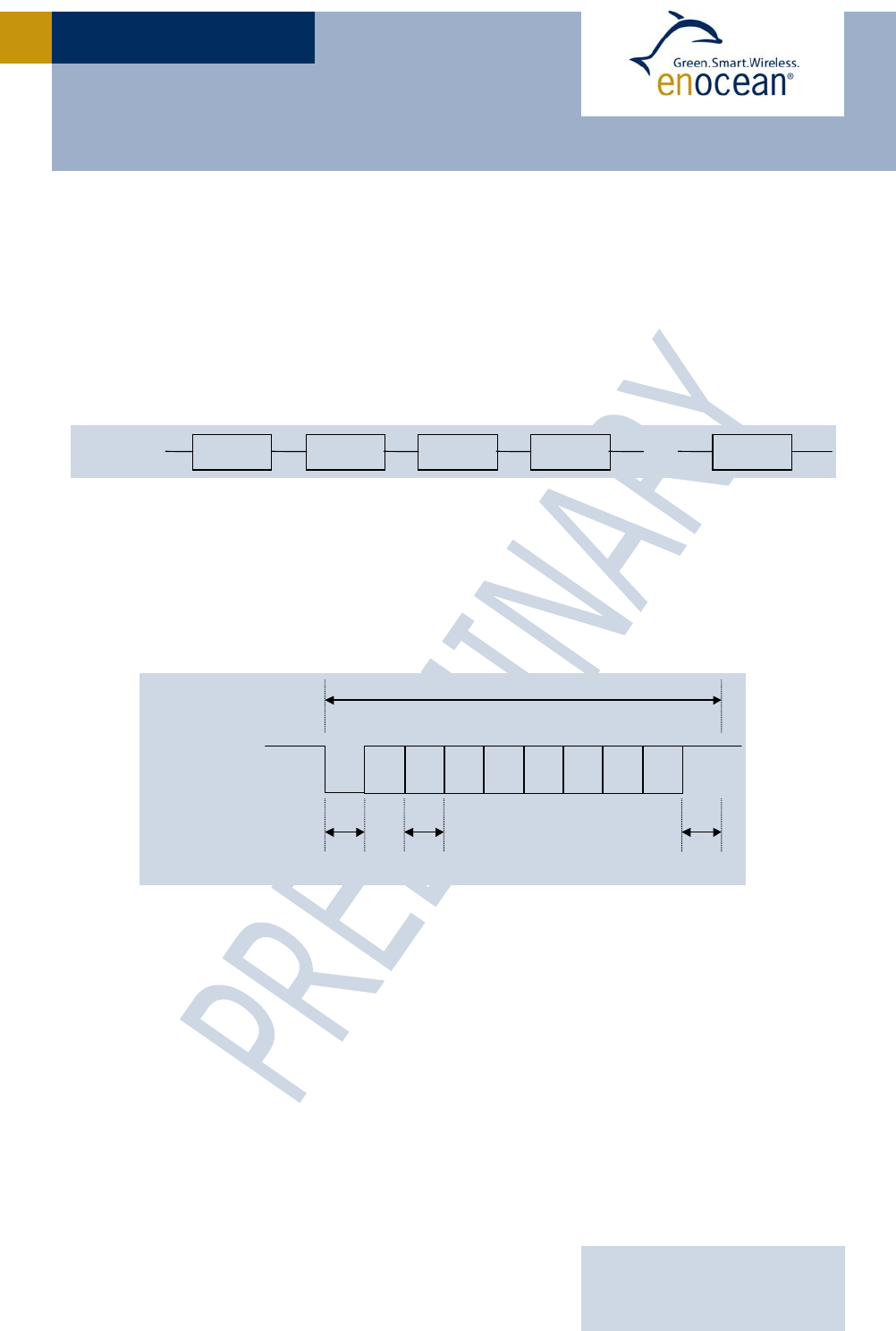
A.1.1 Message format
The following figure shows the message format. A data block of length n is composed of 2
synchronization bytes, 1 octet for the header and n-1 octets for the message data.
Message format for asynchronous serial communication
A.1.2 Octet signals and bit order
9600 bps; 8 data bits, no parity bit, one start bit, one stop bit
Line idle is binary 1 (standard)
Each character has one start bit (binary 0), 8 information bits (least significant bit first)
and one stop bit (binary 1)
Signals and bit order sending a byte
TxD Sync Header Byte0 ByteN-1
...
Sync
D0
STA D1 D2 D3 D4 D5 D6 D7 STOP
TxD 5V
0V
Bit
Time
Bit
T
ime
Bit
Time
Byte
i

USER MANUAL V0.92
EnOcean GmbH
Kolpingring 18a
82041 Oberhaching
Germany
Phone +49.89.67 34 689-0
Fax +49.89.67 34 689-50
info@enocean.com
www.enocean.com
Subject to modifications
TCM200C / 220C User Manual V0.92
June 5, 2008 5:18 PM
Page 21/24
TCM200C / 220C
A.1.3 Description of serial data structure
Bit 7 Bit 0
SYNC_BYTE1 (A5 Hex)
SYNC_BYTE0 (5A Hex)
H_SEQ LENGTH
ORG
DATA_BYTE3
DATA
_
BYTE2
DATA_BYTE1
DATA_BYTE0
ID_BYTE3
ID_BYTE2
ID_BYTE1
ID_BYTE0
STATUS
CHECKSUM
SYNC_BYTE 0..1 (8 bit each) Synchronization Bytes
H_SEQ (3 bit) Header identification: always 0 in TCM200C/220C
LENGTH (5 bit) Number of octets following the header octet (11 dec)
ORG (8 bit) Type of telegram (see detailed description below)
DATA_BYTE 0..3 (8 bit each) Data bytes 0..3 (see detailed description below)
ID_BYTE 0..3 (8 bit each) 32-bit transmitter ID
STATUS (8 bit) Status field (see detailed description below)
CHECKSUM (8 bit) Checksum (Last LSB from addition of all octets except
sync bytes and checksum)
A.1.4 Detailed description of ORG field
ORG field
(decimal) Acronym Description
5 RPS Telegram from a PTM switch module received
(e.g. PTM 100 or PTM 200)
6 1BS 1 byte data telegram from a STM sensor module
(e.g. STM 250)
7 4BS 4 byte data telegram from a STM sensor module
(e.g. STM 100)
8
HRC Telegram from a CTM module received
0-4, 9-255
- Reserved

USER MANUAL V0.92
EnOcean GmbH
Kolpingring 18a
82041 Oberhaching
Germany
Phone +49.89.67 34 689-0
Fax +49.89.67 34 689-50
info@enocean.com
www.enocean.com
Subject to modifications
TCM200C / 220C User Manual V0.92
June 5, 2008 5:18 PM
Page 22/24
TCM200C / 220C
A.1.5 Detailed description of STATUS field
If ORG = 5 (Telegram from a PTM switch module):
7 0
Reserved T21 NU RP_COUNTER
Reserved (2 bit) For future use
T21 (1 bit) T21=0 Æ PTM switch module of type 1,
T21=1 Æ PTM switch module of type 2
NU (1 bit) NU=1 Æ N-message, NU=0 Æ U-message.
RP_COUNTER (4 bit) =0..15 Repeater level: 0 is original message (not repeated)
IMPORTANT NOTE FOR SYSTEMS USING AN ENOCEAN RADIO REPEATER:
Within toggle switch applications using the serial receiver mode in combination
with a separate repeater, please ensure that no serial command interpretation
error may occur at the connected control unit. A toggle signal means that the
same telegram is sent for switching something on and off. If e.g. the light is
switched on receiving the I-button telegram from a PTM 200C, the repeated tele-
gram (delay <100ms) may switch off the light again. It is therefore mandatory to
interpret the RP_COUNTER field. If a repeated telegram (RP_COUNTER>0) is re-
ceived it has to be verified if the same telegram with a lower RP_COUNTER state
has already been received in the previous 100 ms. In this case the repeated mes-
sage has to be discarded.
PTM switch modules of Type 2 (e.g. PTM 200C) allow interpretation of operating two but-
tons simultaneously:
N-message received Æ Only one or two pushbuttons have been pressed.
U-message received Æ No pushbutton was pressed when activating the energy genera-
tor, or more than two pushbuttons have been pressed.
Note for telegrams from PTM transmitters: Due to the mechanical hysteresis of the energy
bow, in most rocker switch device implementations, pressing the rocker sends an N-
message and releasing the rocker sends a U-message!
If ORG = 6, 7 or 8 (all other telegrams):
7 0
Reserved RP_COUNTER
Reserved (4 bit) For future use
RP_COUNTER (4 bit) Repeater level: 0 is original message (not repeated)
Please consider the “IMPORTANT NOTE” above!

USER MANUAL V0.92
EnOcean GmbH
Kolpingring 18a
82041 Oberhaching
Germany
Phone +49.89.67 34 689-0
Fax +49.89.67 34 689-50
info@enocean.com
www.enocean.com
Subject to modifications
TCM200C / 220C User Manual V0.92
June 5, 2008 5:18 PM
Page 23/24
TCM200C / 220C
A.1.6 Detailed description of DATA_BYTE 3..0 fields
If ORG = 5 and NU = 1 (N-message from a PTM switch module):
DATA_BYTE2..0 always = 0
DATA_BYTE3 as follows:
7 0
RID UD PR SRID SUD SA
RID (2 bit) Rocker ID, from left (A) to right (D): 0, 1, 2 and 3 (de-
cimal)
UD (1 bit) UD=1 Æ O-button, UD=0 Æ I-button
PR (1 bit) PR=1 Æ Energy bow pressed, PR=0 Æ Energy bow re-
leased
SRID (2 bit) Second Rocker ID, from left to right: 0, 1, 2 and 3
SUD (1 bit) (Second) SUD=1 Æ O-button, SUD=0 Æ I-button
SA (1 bit) SA=1 Æ Second action (2 buttons pressed
simultaneously), SA=0 Æ No second action
If ORG = 5 and NU = 0 (U-message from a PTM switch module):
DATA_BYTE2..0 always = 0
DATA_BYTE3 as follows:
7 0
BUTTONS PR Reserved
BUTTONS (3 bit) Number of simultaneously pressed buttons, as following:
PTM 100 (Type1): PTM200 (Type2):
0 = 0 Buttons 0 = 0 Button
1 = 2 Buttons 1 = not possible
2 = 3 Buttons 2 = not possible
3 = 4 Buttons 3 = 3 or 4 buttons
4 = 5 Buttons 4 = not possible
5 = 6 Buttons 5 = not possible
6 = 7 Buttons 6 = not possible
7 = 8 Buttons 7 = not possible
PR (1 bit) PR = 1 Æ Energy bow pressed,
PR = 0 Æ Energy bow released
Reserved (4 bit) for future use
If ORG = 6 (Telegram from a 1 Byte STM sensor):
DATA_BYTE2..0 always = 0
DATA_BYTE3 Sensor data byte.

USER MANUAL V0.92
EnOcean GmbH
Kolpingring 18a
82041 Oberhaching
Germany
Phone +49.89.67 34 689-0
Fax +49.89.67 34 689-50
info@enocean.com
www.enocean.com
Subject to modifications
TCM200C / 220C User Manual V0.92
June 5, 2008 5:18 PM
Page 24/24
TCM200C / 220C
If ORG = 7 (Telegram from a 4 Byte STM sensor):
DATA_BYTE3 Value of third sensor analog input (AD_2)
DATA_BYTE2 Value of second sensor analog input (AD_1)
DATA_BYTE1 Value of first sensor analog input (AD_0)
DATA_BYTE0 Sensor digital inputs as follows:
7 0
Reserved DI_3 DI_2 DI_1 DI_0
If ORG = 8 (Telegram from a HRC transmitter):
DATA_BYTE2..0 always = 0
DATA_BYTE3 as follows:
7 0
RID UD PR SR Reserved
RID (2 bit) Rocker ID, from left (A) to right (D): 0, 1, 2 and 3
UD (1 bit) UD=1 Æ O-button, UD=0 Æ I-button
PR (1 bit) PR=1 Æ Button pushed, PR=0 Æ Button released
SR (1 bit) SR=1 Æ Store, SR=0 Æ Recall (see note)
Reserved (3 bit) for future use
Note: The bit SR is used only when the lower 3 Bits from ID_BYTE0 = 0b111 (scene
switch), and RID ≠ 0 (indicates that the memory buttons M0-M5 are operated in the hand-
held remote control).