EnOcean TCM320U TRANSCEIVER MODULE User Manual
EnOcean GmbH TRANSCEIVER MODULE
UserManual.wiki
>
EnOcean
>
TCM320U User Manual
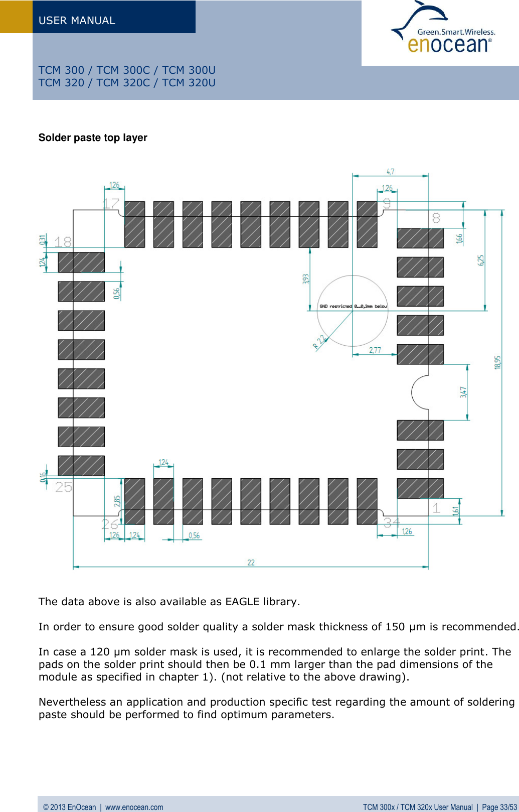
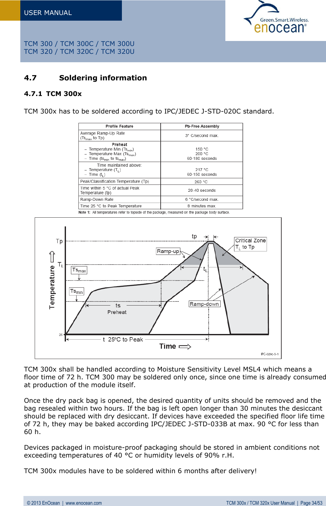
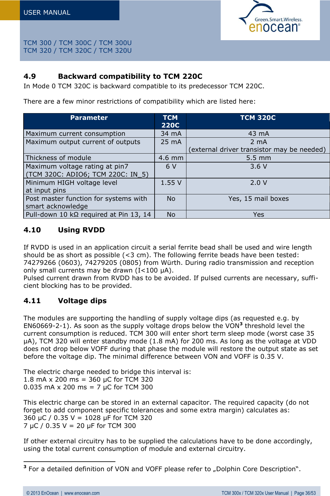
User Manual
Navigation menu
Upload a User Manual
Namespaces
Wiki Guide
HTML
PDF
Info
Views
User Manual
Discussion / Help
Navigation