EnOcean TCM515B 2.4 GHz Bluetooth Low Energy (BLE) Transceiver User Manual
EnOcean GmbH 2.4 GHz Bluetooth Low Energy (BLE) Transceiver
UserManual.wiki
>
EnOcean
>
TCM515B User Manual
User Manual
Navigation menu
Upload a User Manual
Namespaces
Wiki Guide
HTML
PDF
Info
Views
User Manual
Discussion / Help
Navigation

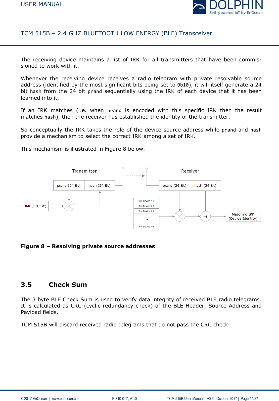
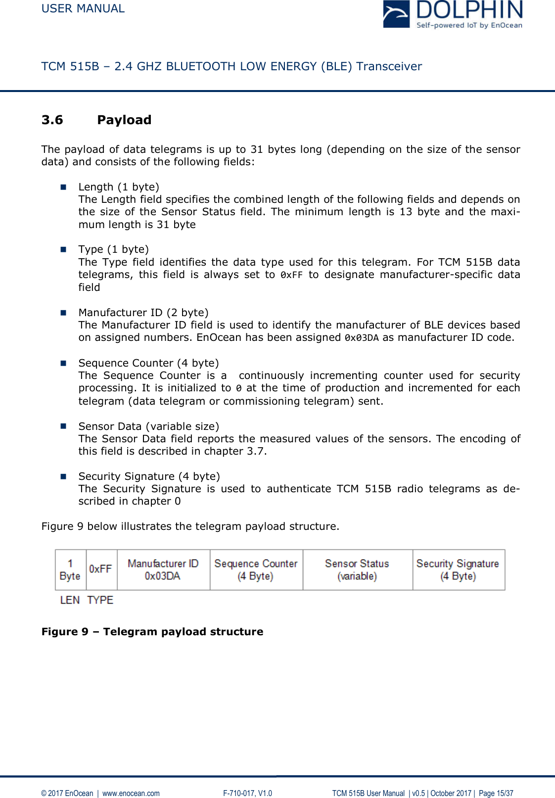
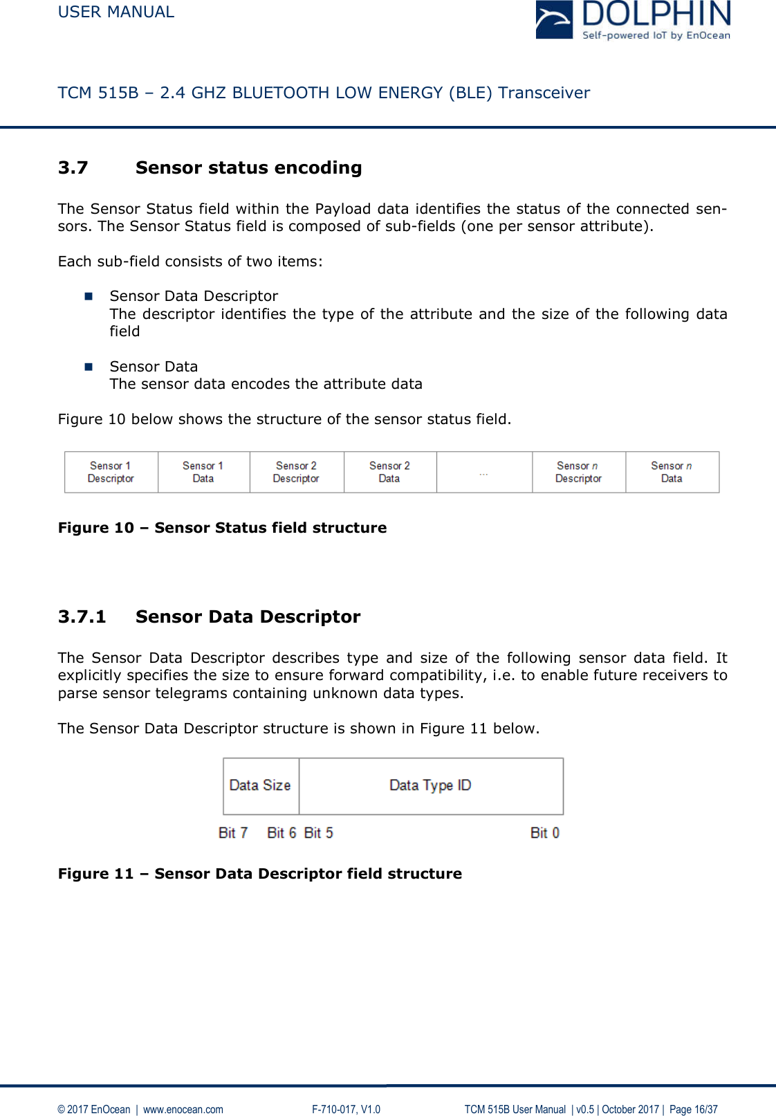
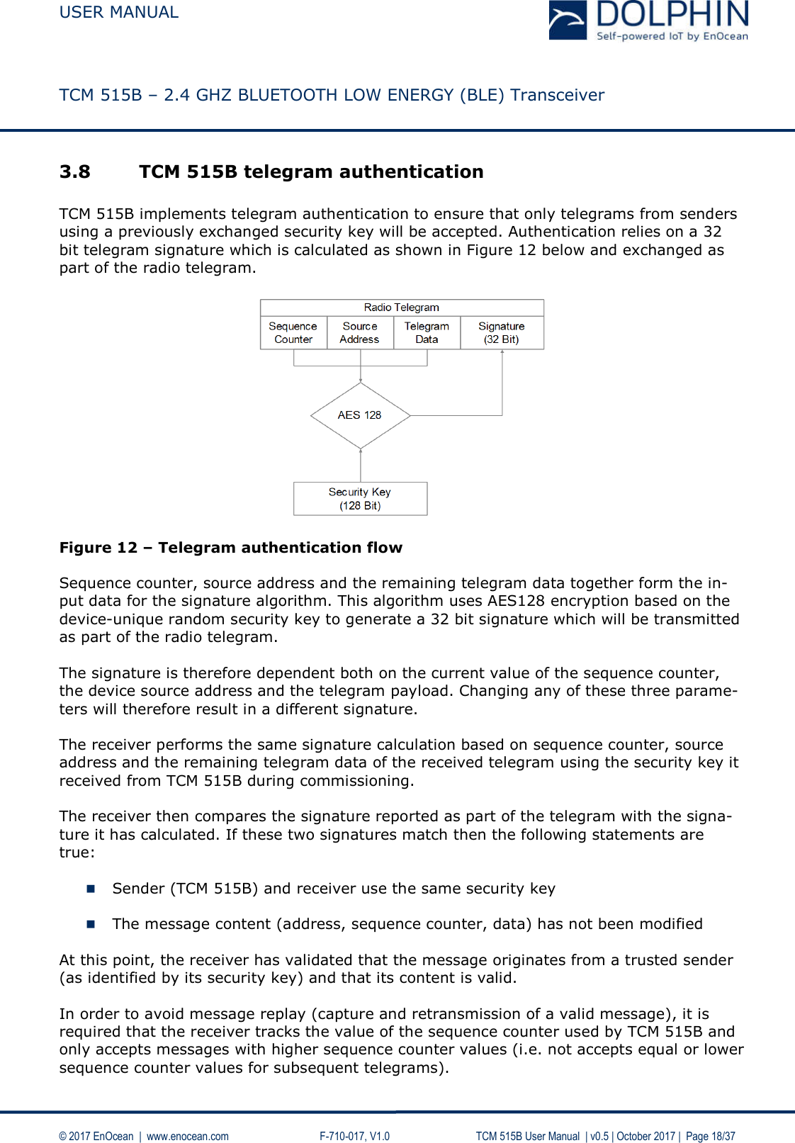
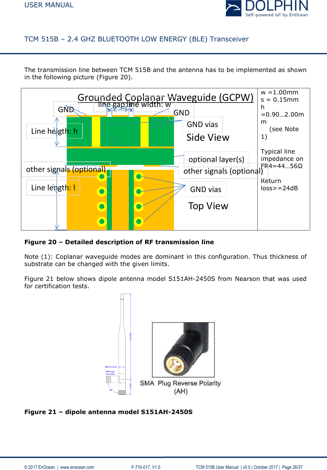
![USER MANUAL TCM 515B – 2.4 GHZ BLUETOOTH LOW ENERGY (BLE) Transceiver © 2017 EnOcean | www.enocean.com F-710-017, V1.0 TCM 515B User Manual | v0.5 | October 2017 | Page 17/37 3.7.2 Sensor Status The Sensor Status field encodes the current status (last reported value) of a sensor. As described above, the type of the sensor data is identified by the Data Type ID field and its size is identified by the Data Size field of the preceding Sensor Data Descriptor. Table 3 below shows the sensor status encoding used by TCM 515B. Table 3 – Sensor status encoding ID Type Size[bytes]signed Minimum Maximum Unit Encoding(Input = x)Measurementtoo lowMeasurementInvalid 0x00 Temperature 2 yes -327.67 327.66 °C 100 * x 0x8000 0x7FFF0x01 Voltage 2 yes -16 383.5 16 383.5 mV 2 * x 0x8000 0x7FFF0x02 Battery level 1 no 0 126.5 % 2 * x 0xFF 0xFE0x03 Current 2 yes -32 767 32 766μA x 0x8000 0x7FFF0x04 Illuminance(wide angle)2 no 0 65 533 lx x 0xFFFF 0xFFFE0x05 Illuminance (Narrow angle)2 no 0 65 533 lx x 0xFFFF 0xFFFE0x06 Relative humidity 1 no 0 126.5 % 2 * x 0xFF 0xFE0x07 Pressure 2 yes -32 767 32 766 hPa x 0x8000 0x7FFF0x08 Distance 2 no 0 ~1023.95 cm 64 * x 0xFFFF 0xFFFE0x09 Gas concentration 2 no 0 32 766.5 ppm 2 * x 0xFFFF 0xFFFE0x0A Acceleration 2 yes ~-16 ~16 G 2048 * x 0x8000 0x7FFFID Type Size[bytes]0x20 Occupancy 1 0x00: Generic Error0x01:Not occupied0x02: Occupied0x21 Smoke 1 0x00:Generic error0x01:No smoke0x02: Smoke(ion chamber)0x01:Up0x02: Right0x05:Up to right0x06: Right to down0x09:Up to left0x0A:Left to down0x23 Open/closed 1 0x00:Generic error0x01:Closed0x02:Open0x3B Device descriptor Variable0x3C Error report 1 0x00: No error0x3D User data Variable0x3E Commissioning 26 Commissioning telegram: 4 byte Sequence Counter + 6 byte Source Address + 16 byte Private KeyOther values: Application specificAll values: Application specific, Size defined by descriptorAll values: Application specific, Size defined by descriptorEnumerationsSystem MessagesEnumerated values0x08: Left to up0x07: Down to left0x00:Generic error0x03:Standby0x03: Smoke(opt. chamber)0x03: Down0x0B: Down to right0x22 Mechanical handle 10x04: Smoke(both chambers)0x04: Left0x0C: Right to up](https://usermanual.wiki/EnOcean/TCM515B/User-Guide-3679698-Page-17.png)