EnOcean TCM515B 2.4 GHz Bluetooth Low Energy (BLE) Transceiver User Manual
EnOcean GmbH 2.4 GHz Bluetooth Low Energy (BLE) Transceiver
EnOcean >
User Manual

USER MANUAL
TCM 515B – 2.4 GHZ BLUETOOTH LOW ENERGY (BLE) Transceiver
© 2017 EnOcean | www.enocean.com F-710-017, V1.0 TCM 515B User Manual | v0.5 | October 2017 | Page 1/37
Patent protected:
WO98/36395, DE 100 25 561, DE 101 50 128,
WO 2004/051591, DE 103 01 678 A1, DE 10309334,
WO 04/109236, WO 05/096482, WO 02/095707,
US 6,747,573, US 7,019,241
Observe precautions! Electrostatic sensitive devices!
14 December 2017

USER MANUAL
TCM 515B – 2.4 GHZ BLUETOOTH LOW ENERGY (BLE) Transceiver
© 2017 EnOcean | www.enocean.com F-710-017, V1.0 TCM 515B User Manual | v0.5 | October 2017 | Page 2/37
REVISION HISTORY
The following major modifications and improvements have been made to this document:
Version
Author Reviewer
Date Major Changes
0.1 MKA MKA 15.02.2017
Initial Release
0.2 MKA MKA 14.07.2017
Update regarding operation conditions
0.3 MKA MKA 19.09.2017
Added detailed pin mapping
0.4 RS MKA 19.09.2017
Added antenna options and descriptions
0.5 RS MKA 05.10.2017
Added FCC
labelling requirements, RF exposure
and distance requirements, FCC and ISED certifi-
cates
0.6 RS 14.12.2017
Updated chapters to RF exposure
Published by EnOcean GmbH, Kolpingring 18a, 82041 Oberhaching, Germany
www.enocean.com, info@enocean.com, phone +49 (89) 6734 6890
© EnOcean GmbH, All Rights Reserved
Important!
This information describes the type of component and shall not be considered as assured
characteristics. No responsibility is assumed for possible omissions or inaccuracies. Circuitry
and specifications are subject to change without notice. For the latest product specifica-
tions, refer to the EnOcean website: http://www.enocean.com.
As far as patents or other rights of third parties are concerned, liability is only assumed for
modules, not for the described applications, processes and circuits.
EnOcean does not assume responsibility for use of modules described and limits its liability
to the replacement of modules determined to be defective due to workmanship. Devices or
systems containing RF components must meet the essential requirements of the local legal
authorities.
The modules must not be used in any relation with equipment that supports, directly or
indirectly, human health or life or with applications that can result in danger for people,
animals or real value.
Components of the modules are considered and should be disposed of as hazardous waste.
Local government regulations are to be observed.
Packing: Please use the recycling operators known to you.

USER MANUAL
TCM 515B – 2.4 GHZ BLUETOOTH LOW ENERGY (BLE) Transceiver
© 2017 EnOcean | www.enocean.com F-710-017, V1.0 TCM 515B User Manual | v0.5 | October 2017 | Page 3/37
TABLE OF CONTENT
1 GENERAL DESCRIPTION ................................................................................. 5
1.1 Basic functionality ......................................................................................... 5
1.2 Technical data ............................................................................................... 6
1.3 Physical dimensions ....................................................................................... 6
1.4 Environmental conditions ............................................................................... 6
1.5 Packaging information .................................................................................... 6
1.6 Ordering information ..................................................................................... 6
2 FUNCTIONAL INFORMATION ........................................................................... 7
2.1 TCM 515B Device Interface ............................................................................. 7
2.1.1 Signal Description .................................................................................. 8
2.2 High-level operation principle .......................................................................... 8
2.3 Radio functionality ......................................................................................... 9
2.4 Radio transmission sequence ........................................................................ 10
2.5 Radio reception sequence ............................................................................. 10
2.6 User-defined radio channels .......................................................................... 10
3 Telegram format ......................................................................................... 11
3.1 Preamble .................................................................................................... 11
3.2 Access Address ........................................................................................... 11
3.3 Header ....................................................................................................... 11
3.4 Source address ........................................................................................... 12
3.4.1 Static source address mode .................................................................. 12
3.4.2 Private resolvable source address mode ................................................. 13
3.5 Check Sum ................................................................................................. 14
3.6 Payload ...................................................................................................... 15
3.7 Sensor status encoding ................................................................................ 16
3.7.1 Sensor Data Descriptor ......................................................................... 16
3.7.2 Sensor Status...................................................................................... 17
3.8 TCM 515B telegram authentication ................................................................ 18
3.9 ESP3 Interface ............................................................................................ 19
3.9.1 ESP3 Data Format................................................................................ 19
4 DEVICE INTEGRATION ................................................................................. 20
4.1 Recommended PCB Footprint ........................................................................ 20
4.2 Antenna options .......................................................................................... 21
4.2.1 General antenna requirements for TCM 515B .......................................... 21
4.2.2 Specific antenna requirements for European Union................................... 21
4.2.3 Specific antenna requirements for US / Canada ....................................... 21
4.2.4 Antenna Description ............................................................................. 21
4.2.4.1 Whip Antenna ................................................................................... 21
4.2.4.2 Meandered PCB Antenna .................................................................... 23
4.2.4.3 Dipole antenna requirements .............................................................. 25
4.3 Soldering information .................................................................................. 29

USER MANUAL
TCM 515B – 2.4 GHZ BLUETOOTH LOW ENERGY (BLE) Transceiver
© 2017 EnOcean | www.enocean.com F-710-017, V1.0 TCM 515B User Manual | v0.5 | October 2017 | Page 4/37
4.4 Device handling instructions ......................................................................... 29
4.5 Device operation instructions ........................................................................ 30
4.6 Tape & Reel specification .............................................................................. 31
5 APPLICATION INFORMATION ........................................................................ 32
5.1 Transmission range ............................................................................................ 32
6 REGULATORY INFORMATION......................................................................... 33
6.1 CE (RED) for European Union ........................................................................ 33
6.2 FCC (United States) Certificate ...................................................................... 34
6.2.1 FCC (United States) regulatory statement ............................................... 35
6.2.2 FCC (United States) labeling requirements .............................................. 35
6.2.3 FCC (United States) RF exposure statement ............................................ 35
6.3 ISED (Industry Canada) Technical Acceptance Certificate ................................. 36
6.3.1 ISED (Industry Canada) regulatory statement ......................................... 37
6.3.2 ISED (Industry Canada) RF exposure statement ...................................... 37
USER MANUAL
TCM 515B – 2.4 GHZ BLUETOOTH LOW ENERGY (BLE) Transceiver
© 2017 EnOcean | www.enocean.com F-710-017, V1.0 TCM 515B User Manual | v0.5 | October 2017 | Page 5/37
1 GENERAL DESCRIPTION
1.1 Basic functionality
TCM 515B provides radio transceiver functionality (telegram transmission and reception)
according to the Bluetooth Low Energy standard in the 2.4 GHz radio band. TCM 515B re-
ceives and transmits radio telegrams based on a whip or PCB antenna connected via the
host PCB.
TCM 515B is primarily intended for use within energy harvesting wireless sensors where it
will provide the required radio functionality. To meet this requirement, TCM 515B provides
a radio application programming interface (API) for transmission and reception of 2.4 GHz
BLE radio telegrams. This radio API can be used by sensor applications running on TCM
515B to transmit and receive radio telegrams.
Additionally, TCM 515B provides an ESP3 interface to an external host which can be used to
transmit and receive data tele-grams.
TCM 515B provides an I2C interface which can be used to connect external sensors.
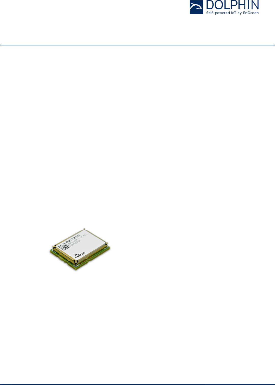
TCM 515B is implemented as 31 pin reflow-solderable module in an optimized form factor
to enable size constrained applications. The module design is mechanically compatible with
the other members of the TCM 515 radio transceiver family to enable reuse.
Figure 1 below shows TCM 515B.
Figure 1 – TCM 515B outline
USER MANUAL
TCM 515B – 2.4 GHZ BLUETOOTH LOW ENERGY (BLE) Transceiver
© 2017 EnOcean | www.enocean.com F-710-017, V1.0 TCM 515B User Manual | v0.5 | October 2017 | Page 6/37
1.2 Technical data
Antenna External 50 Ohm or whip antenna (connected at host board)
Supported Radio Frequency Range 2402 … 2480 MHz
Default Radio Channels Advertising on Channel 37, 38 and 39
Receiver Sensitivity (at 25°C)
(1)
Minimum: -92dBm / Typical: –95 dBm
Transmit Power (at 25°C) Adjustable up to +4 dBm
Power Supply 3.3 V +- 10%
Serial Host Interface UART according to ESP3 Standard with Turbo Mode Option
Current Consumption (typ, at 25°C) 15 mA
Module Dimensions 19.0 x 14.7 x 3.0 mm (each dimension +-0.3 mm)
Note (1): Receiver sensitivity is based on the combination of 3 subtelegrams
1.3 Physical dimensions
Module Dimensions 19.0 x 14.7 x 3.0 mm (each dimension +-0.3 mm)
Module Weight 1 g
1.4 Environmental conditions
Operating Temperature -25°C ... 85°C
Storage Temperature -25°C ... 85°C
Humidity 0% to 95% r.h. (non-condensing)
1.5 Packaging information
Packaging Unit 250 units
Packaging Method Tape and reel
1.6 Ordering information
Type Ordering Code Frequency
TCM 515B S3223-K515 2.4 GHz (BLE)
USER MANUAL
TCM 515B – 2.4 GHZ BLUETOOTH LOW ENERGY (BLE) Transceiver
© 2017 EnOcean | www.enocean.com F-710-017, V1.0 TCM 515B User Manual | v0.5 | October 2017 | Page 7/37
2 FUNCTIONAL INFORMATION
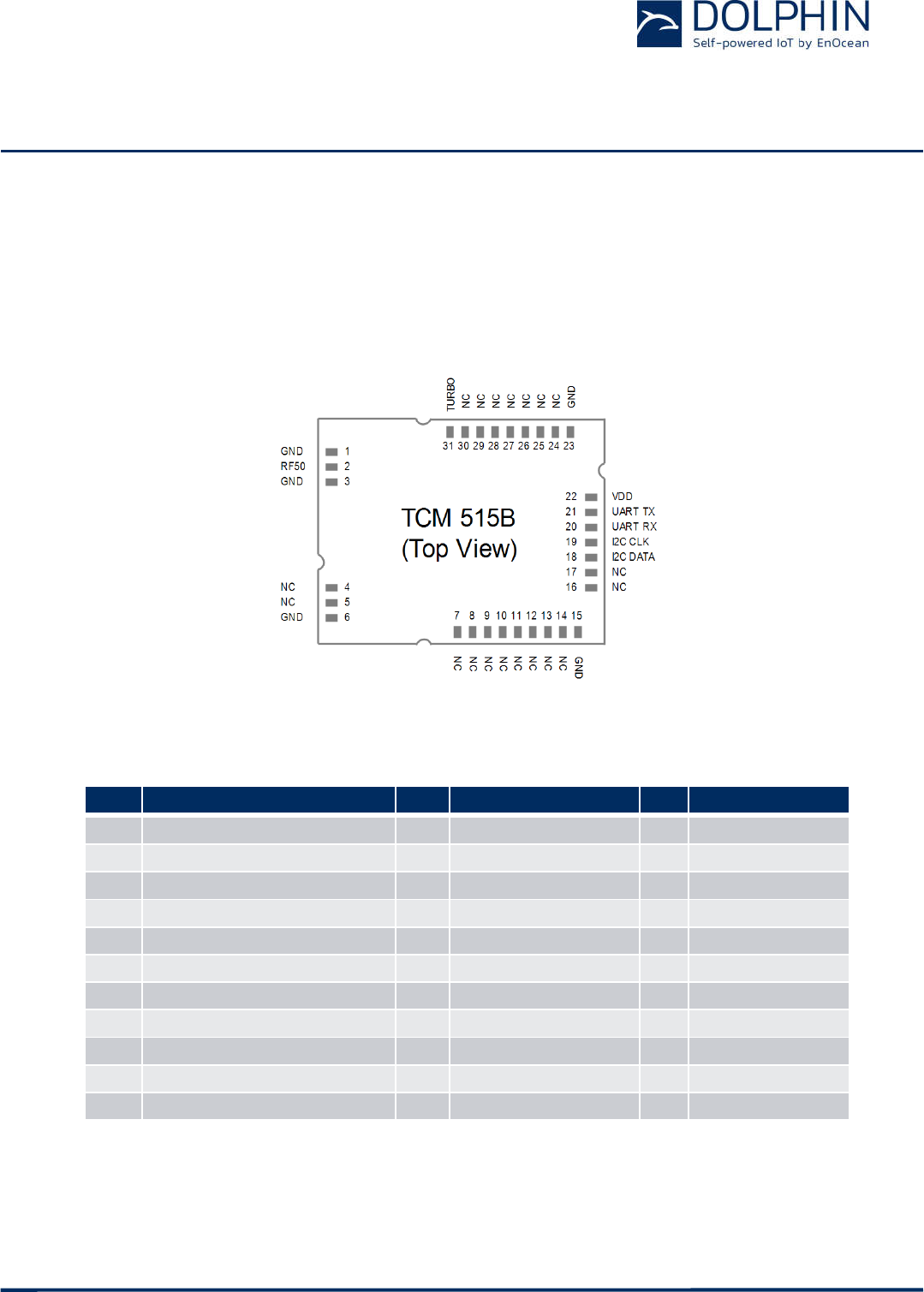
2.1 TCM 515B Device Interface
TCM 515B implements a 31 pin reflow-solderable interface. Solder mask data is available
on request from EnOcean. The pin assignment (as seen from the top of the device) is
shown in Figure 2 below.
Figure 2 – TCM 515B device interface
Table 1 below summarizes the signal assignment.
PIN NAME PIN
NAME PIN NAME
1 GND 12 Digital IO 23 GND
2 ANTENNA (50 Ohms) 13 Digital IO 24 Debug
3 GND 14 Digital IO 25 Debug
4 Digital IO 15 GND 26 Digital IO
5 Digital IO 16 Analog / Digital IO 27 Digital IO
6 GND 17 Analog / Digital IO 28 Digital IO
7 Analog / Digital IO 18 I2C Data 29 Digital IO
8 Analog / Digital IO 19 I2C CLK 30 Digital IO
9 Analog / Digital IO / 32 kHz OSC 20 UART RX (Input) 31 TURBO
10 Analog / Digital IO / 32 kHz OSC 21 UART TX (Output)
11 Analog/ Digital IO 22 VDD
Table 1 - TCM 515B device interface pin assignment

USER MANUAL
TCM 515B – 2.4 GHZ BLUETOOTH LOW ENERGY (BLE) Transceiver
© 2017 EnOcean | www.enocean.com F-710-017, V1.0 TCM 515B User Manual | v0.5 | October 2017 | Page 8/37
2.1.1 Signal Description
TCM 515B is supplied by the VDD and GND Pins. The required supply voltage is 3.3V with a
tolerance of no more than +-10%.
TCM 515B receives and transmits data based on a 50Ω whip antenna connected to its AN-
TENNA input (Pin 2).
TCM 515B communicates with the external host using the standard ESP3 serial (UART) in-
terface based on the signals UART_TX (Pin 21, direction from TCM 515B to external host)
and UART_RX (Pin 20, direction from external host to TCM 51Z).
The default interface speed of the ESP3 interface is 57600 bit per second (the exact speed
is 57347 Bit per second, a deviation of -0.04%).
It is possible to select faster communication speeds of 115200, 230400 and 460800 bit per
second during operation using the ESP3 CO_SET_BAUDRATE command.
Additionally it is possible to change the default ESP3 interface speed at power up from
57.600 Bit per second to 460.800 Bit per second by connecting the TURBO input (Pin 31) to
Ground. Subsequent modification of the interface speed during operation using the
CO_SET_BAUDRATE command is always possible irrespective of the state of the TURBO
input pin.
TCM 515B provides one or two I2C interfaces as primarily means to connect external sen-
sors. Additionally, it provides digital and analog inputs and outputs as well as the option for
an SPI interface.
2.2 High-level operation principle
In receive mode, TCM 515B forwards the content of received BLE radio telegrams (which
pass frame check sum validation) unmodified to the sensor application SW or an external
host via the ESP3 interface. The sensor application can use the data of received telegrams
for instance to adjust parameters such as update intervals.
In transmit mode, TCM 515B receives from the application SW or an external host the pre-
computed message payload. TCM 515B then calculates the frame check sum and appends it
to the message. The full frame (including the Preamble and Start of Frame fields) will then
be transmitted as BLE radio telegram (TX mode).
The sensor application uses an internal or external timer to periodically wake-up and check
the status of the connected sensors. Based on this status information, it will decide if
transmission of a telegram is necessary and if so forward it to the radio routine by means
of its API.

USER MANUAL
TCM 515B – 2.4 GHZ BLUETOOTH LOW ENERGY (BLE) Transceiver
© 2017 EnOcean | www.enocean.com F-710-017, V1.0 TCM 515B User Manual | v0.5 | October 2017 | Page 9/37
2.3 Radio functionality
TCM 515B transmits and receives advertising telegrams within the 2.4 GHz radio frequency
band (2402MHz … 2480MHz) using the BLE advertising frame format.
By default, TCM 515B will use the three BLE advertising channels (BLE Channel 37, 38 and
39) defined for transmission and reception. The transmission of a radio telegram on these
three advertising channels is called an Advertising Event.
Use of different radio channels within the frequency band from 2402 MHz to 2480 MHz is
possible and can be configured by the application software or the external host (via ESP3
interface).
Table 2 below summarizes radio channels supported by TCM 515B.
Radio Channel Frequency Channel Type
BLE Radio Channels
37 2402 MHz BLE Advertising Channel
0 2404 MHz BLE Data Channel
1 2406 MHz BLE Data Channel
…
10 2424 MHz BLE Data Channel
38 2426 MHz BLE Advertising Channel
11 2428 MHz BLE Data Channel
12 2430 MHz BLE Data Channel
…
36 2478 MHz BLE Data Channel
39 2480 MHz BLE Advertising Channel
Custom Radio Channels
40 2403 MHz Custom Radio Channel
41 2405 MHz Custom Radio Channel
…
77 2477 MHz Custom Radio Channel
78 2479 MHz Custom Radio Channel
Table 2 – TCM 515B supported radio channels
USER MANUAL
TCM 515B – 2.4 GHZ BLUETOOTH LOW ENERGY (BLE) Transceiver
© 2017 EnOcean | www.enocean.com F-710-017, V1.0 TCM 515B User Manual | v0.5 | October 2017 | Page 10/37
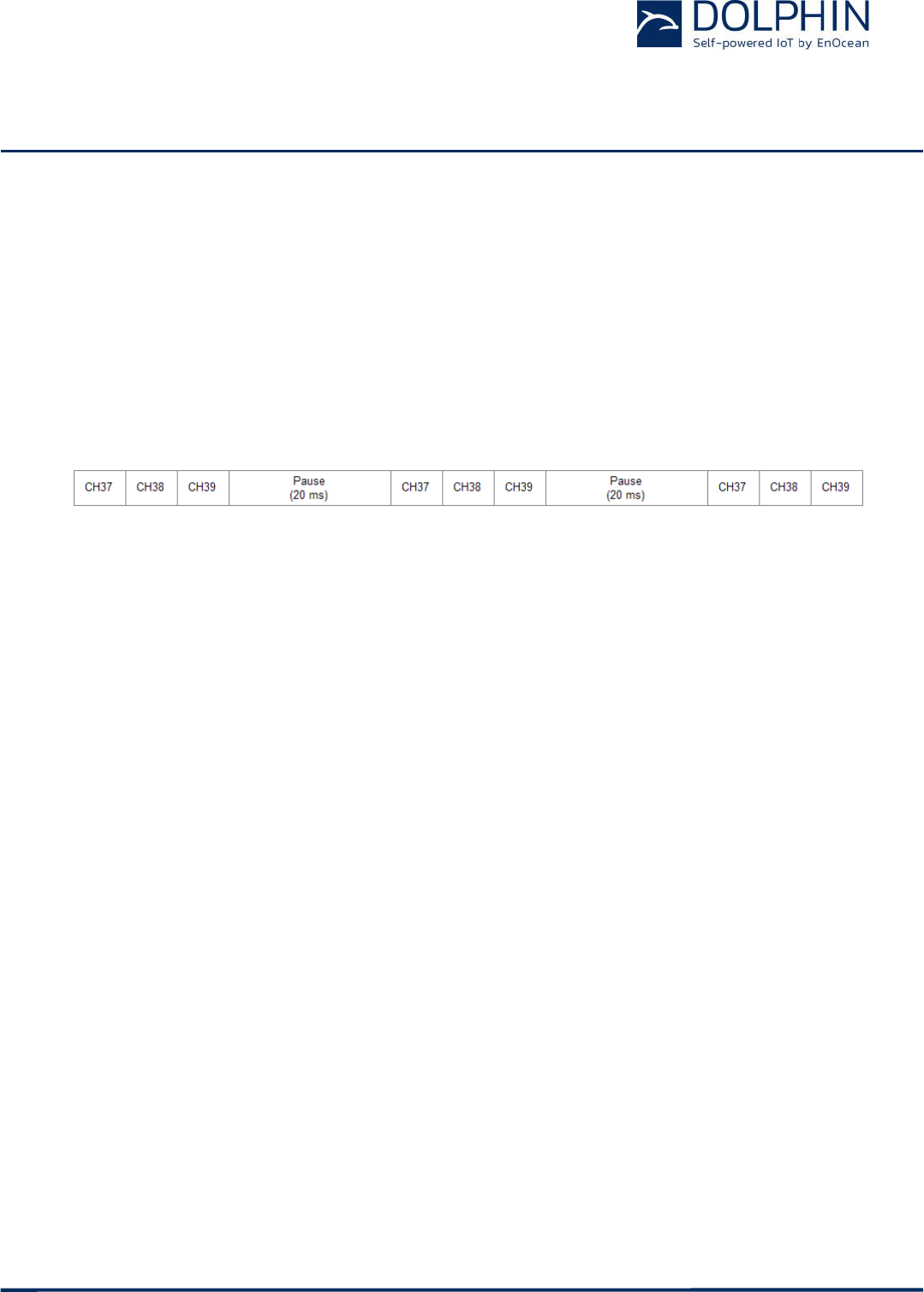
2.4 Radio transmission sequence
TCM 515B transmits telegrams in its standard configuration by using so-called Advertising
Events.
An advertising event is defined as the transmission of the same radio telegram on all se-
lected radio channels (by default this would be on BLE Channel 37, 38 and 39) one after
another with minimum delay in between.
For reliability reasons, TCM 515B will send three redundant advertising events for each
transmission. The resulting transmission sequence is shown in Figure 3 below.
Figure 3 – Default radio transmission sequence
2.5 Radio reception sequence
TCM 515B receives radio telegrams in its standard configuration by monitoring the Adver-
tising Channels (Channel 37, 38 and 39). Alternative channels can be selected via the radio
API or the ESP3 interface.
TCM 515B will continuously scan these channels one after the other for valid data tele-
grams. The time spent on each channel is configurable.
2.6 User-defined radio channels
In certain situations it might be desirable to transmit and receive radio telegrams on chan-
nels other than the three advertising channels.
TCM 515B therefore allows to select the radio channels to be used for the transmission and
reception. The selection of the radio channels is done by the application SW using the radio
API or the external host using the ESP3 interface.
USER MANUAL
TCM 515B – 2.4 GHZ BLUETOOTH LOW ENERGY (BLE) Transceiver
© 2017 EnOcean | www.enocean.com F-710-017, V1.0 TCM 515B User Manual | v0.5 | October 2017 | Page 11/37
3 Telegram format
TCM 515B transmits and receives radio telegrams in the 2.4 GHz band according to BLE
frame structure. For detailed information about the BLE standard, please refer to the appli-
cable specifications.
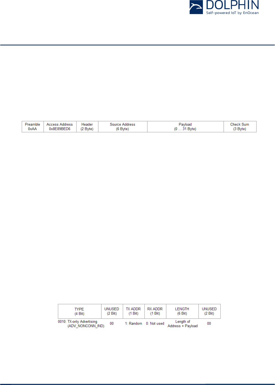
Figure 4 below summarizes the BLE frame structure.
Figure 4 – BLE frame structure
The content of these fields is described in more detail below.
3.1 Preamble
The BLE Preamble is 1 byte long and identifies the start of the BLE frame. The value of the
BLE Preamble is always set to 0xAA.
3.2 Access Address
The 4 byte BLE Access Address identifies the radio telegram type. For advertising frames,
the value of the Access Address is always set to 0x8E89BED6.
3.3 Header
The BLE Header identifies certain radio telegram parameters. Figure 5 below shows the
structure of the BLE header.
Figure 5 – BLE header structure

USER MANUAL
TCM 515B – 2.4 GHZ BLUETOOTH LOW ENERGY (BLE) Transceiver
© 2017 EnOcean | www.enocean.com F-710-017, V1.0 TCM 515B User Manual | v0.5 | October 2017 | Page 12/37
3.4 Source address
The 6 byte BLE Source Address (MAC address) uniquely identifies each TCM 515B product.
TCM 515B supports two source address modes:
Static Source Address mode (default)
In this mode, the source address is constant (but its lower 32 bit can be configured
via radio API)
Private Resolvable Address mode (NFC configurable)
In this mode, the source address changes for each transmission
TCM 515B uses by default the Static Source Address mode. Private Resolvable Address
mode can be selected via the radio API. These two address modes are described in the fol-
lowing chapters.
3.4.1 Static source address mode
By default, TCM 515B uses static source addresses meaning that the source address is con-
stant during normal operation. The structure of TCM 515B static addresses is as follows:
The upper 2 bytes of the source address are used to identify the device type and set
to 0xE500 to designate EnOcean STM 500 multi-sensor type. These two bytes cannot
be changed.
The lower 4 bytes are uniquely assigned to each device.
Figure 6 below illustrates the static address structure used by TCM 515B.
Figure 6 – BLE static source address structure
USER MANUAL
TCM 515B – 2.4 GHZ BLUETOOTH LOW ENERGY (BLE) Transceiver
© 2017 EnOcean | www.enocean.com F-710-017, V1.0 TCM 515B User Manual | v0.5 | October 2017 | Page 13/37
3.4.2 Private resolvable source address mode
For some applications it is desirable to modify (rotate) the source address used by TCM
515B in order to prevent tracking of its radio transmissions. At the same time, each TCM
515B device must remain uniquely identifiable by the receiver.
To achieve these goals, TCM 515B can be configured via radio API to use random resolvable
private addresses.
Using random resolvable private addresses requires that both TCM 515B and the receiver
both know a common key – the so-called Identity Resolution Key (IRK). TCM 515B uses its
device-unique random key as identity resolution key.
For resolvable private addresses, the 48 bit address field is split into two sub-fields:
prand
This field contains a random number which always starts (two most significant bits)
with 0b10. The prand value is changed for each telegram that is transmitted. Indi-
vidual advertising events used to transmit one telegram use the same prand value.
hash
This field contains a verification value (hash) generated from prand using the IRK
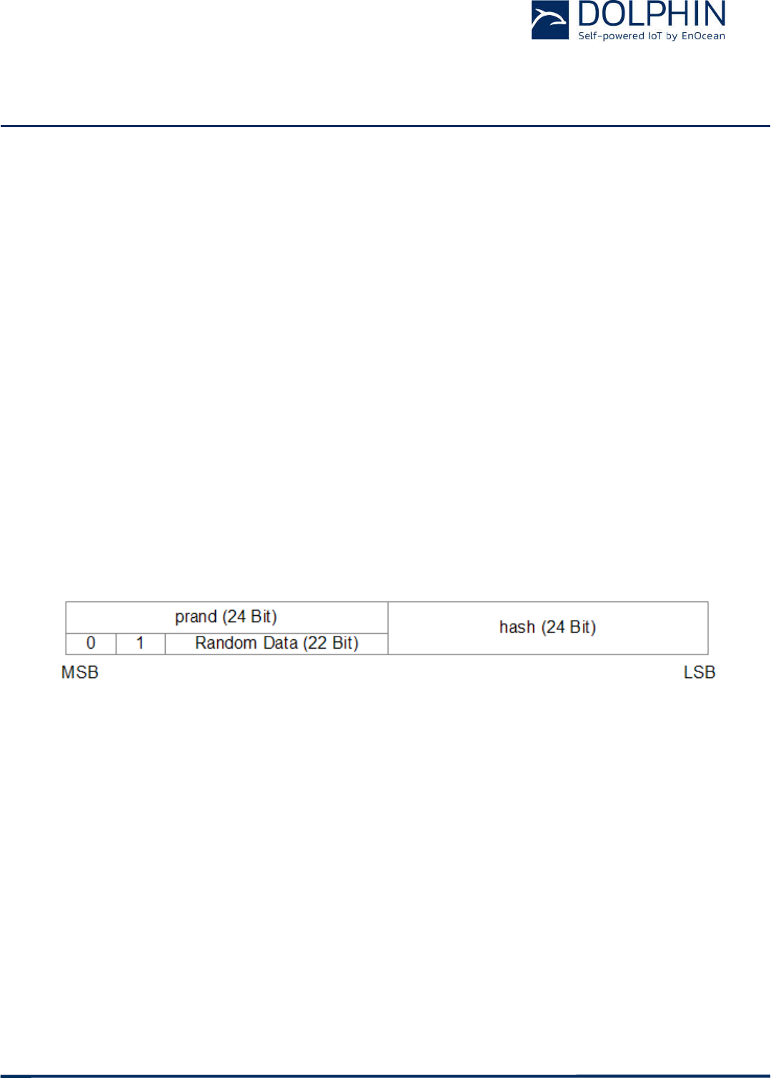
The structure of a random resolvable private address is shown in Figure 7 below.
Figure 7 – BLE private resolvable source address structure
The prand value is encrypted using the IRK. The lowest 24 bit of the result (encrypted
value) are then used as hash.
The concatenation of 24 bit prand and 24 bit hash will be transmitted as 48 bit private re-
solvable source address.
USER MANUAL
TCM 515B – 2.4 GHZ BLUETOOTH LOW ENERGY (BLE) Transceiver
© 2017 EnOcean | www.enocean.com F-710-017, V1.0 TCM 515B User Manual | v0.5 | October 2017 | Page 14/37
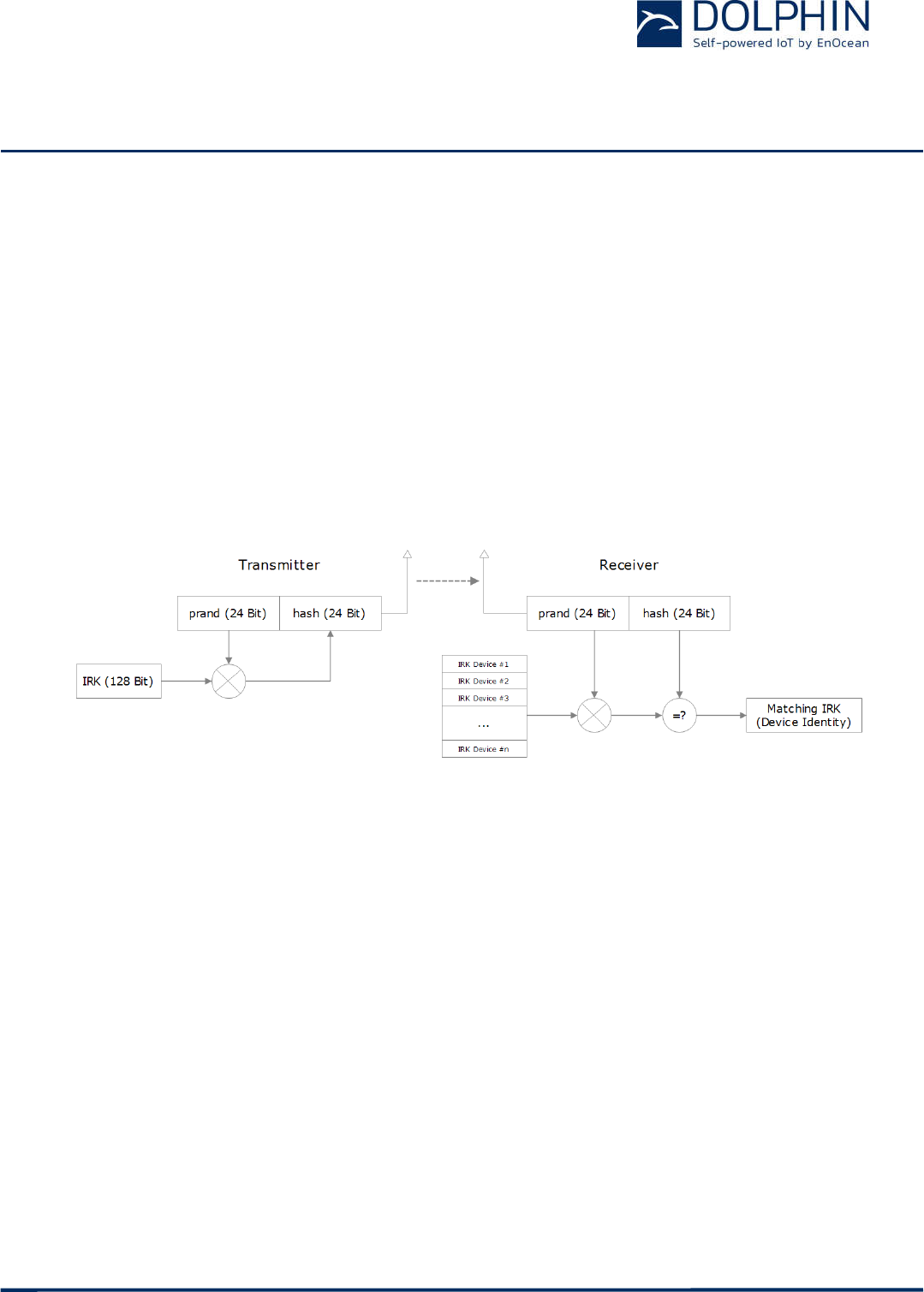
The receiving device maintains a list of IRK for all transmitters that have been commis-
sioned to work with it.
Whenever the receiving device receives a radio telegram with private resolvable source
address (identified by the most significant bits being set to 0b10), it will itself generate a 24
bit hash from the 24 bit prand sequentially using the IRK of each device that it has been
learned into it.
If an IRK matches (i.e. when prand is encoded with this specific IRK then the result
matches hash), then the receiver has established the identity of the transmitter.
So conceptually the IRK takes the role of the device source address while prand and hash
provide a mechanism to select the correct IRK among a set of IRK.
This mechanism is illustrated in Figure 8 below.
Figure 8 – Resolving private source addresses
3.5 Check Sum
The 3 byte BLE Check Sum is used to verify data integrity of received BLE radio telegrams.
It is calculated as CRC (cyclic redundancy check) of the BLE Header, Source Address and
Payload fields.
TCM 515B will discard received radio telegrams that do not pass the CRC check.
USER MANUAL
TCM 515B – 2.4 GHZ BLUETOOTH LOW ENERGY (BLE) Transceiver
© 2017 EnOcean | www.enocean.com F-710-017, V1.0 TCM 515B User Manual | v0.5 | October 2017 | Page 15/37
3.6 Payload
The payload of data telegrams is up to 31 bytes long (depending on the size of the sensor
data) and consists of the following fields:
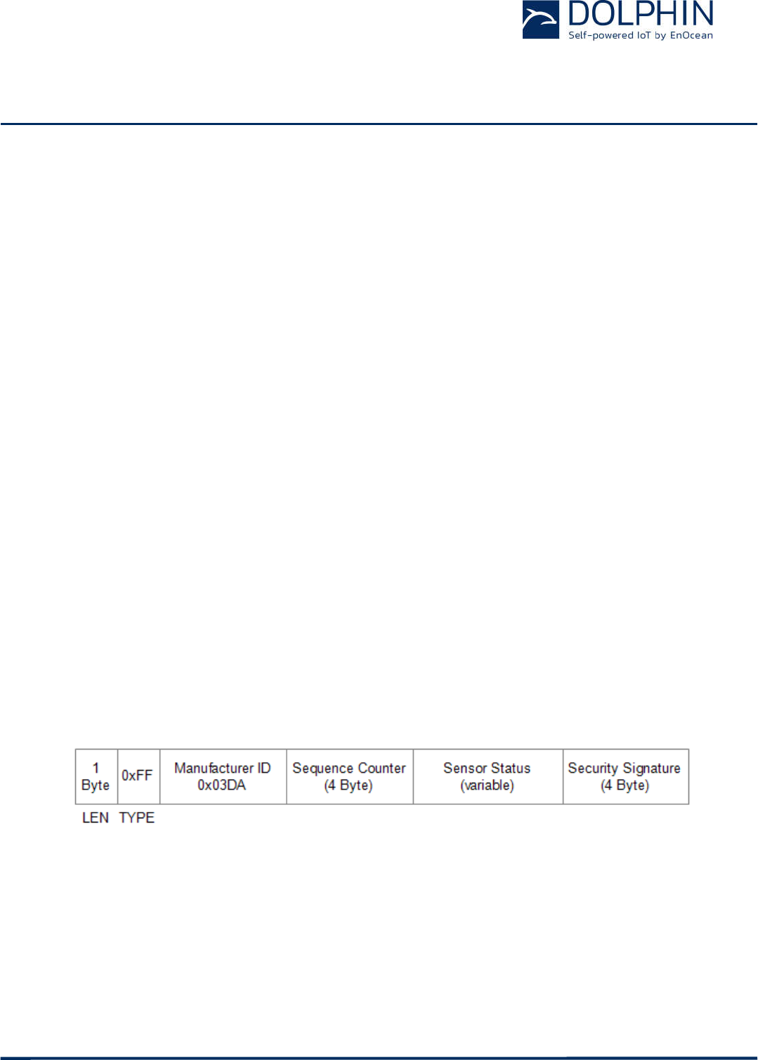
Length (1 byte)
The Length field specifies the combined length of the following fields and depends on
the size of the Sensor Status field. The minimum length is 13 byte and the maxi-
mum length is 31 byte
Type (1 byte)
The Type field identifies the data type used for this telegram. For TCM 515B data
telegrams, this field is always set to 0xFF to designate manufacturer-specific data
field
Manufacturer ID (2 byte)
The Manufacturer ID field is used to identify the manufacturer of BLE devices based
on assigned numbers. EnOcean has been assigned 0x03DA as manufacturer ID code.
Sequence Counter (4 byte)
The Sequence Counter is a continuously incrementing counter used for security
processing. It is initialized to 0 at the time of production and incremented for each
telegram (data telegram or commissioning telegram) sent.
Sensor Data (variable size)
The Sensor Data field reports the measured values of the sensors. The encoding of
this field is described in chapter 3.7.
Security Signature (4 byte)
The Security Signature is used to authenticate TCM 515B radio telegrams as de-
scribed in chapter 0
Figure 9 below illustrates the telegram payload structure.
Figure 9 – Telegram payload structure
USER MANUAL
TCM 515B – 2.4 GHZ BLUETOOTH LOW ENERGY (BLE) Transceiver
© 2017 EnOcean | www.enocean.com F-710-017, V1.0 TCM 515B User Manual | v0.5 | October 2017 | Page 16/37
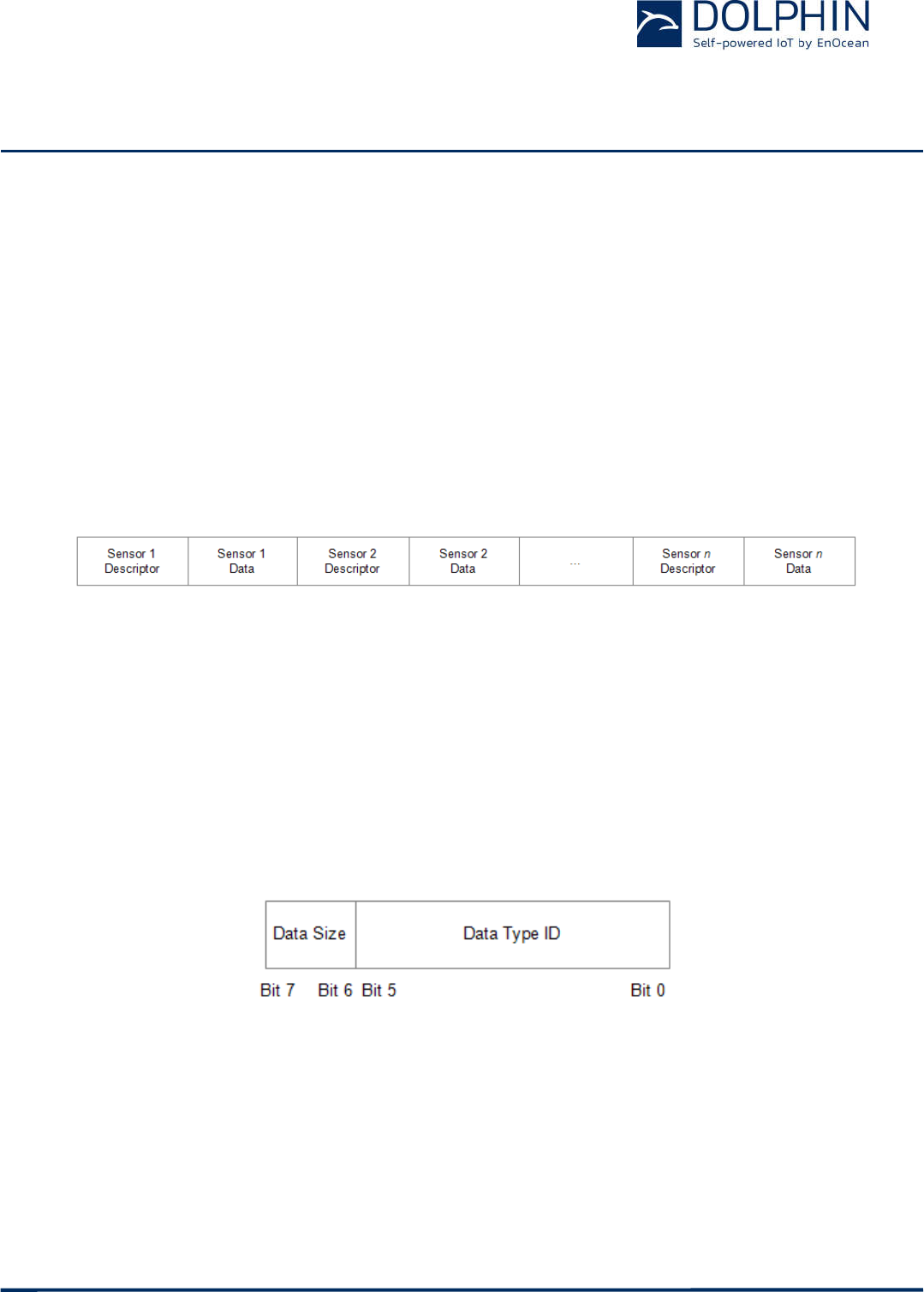
3.7 Sensor status encoding
The Sensor Status field within the Payload data identifies the status of the connected sen-
sors. The Sensor Status field is composed of sub-fields (one per sensor attribute).
Each sub-field consists of two items:
Sensor Data Descriptor
The descriptor identifies the type of the attribute and the size of the following data
field
Sensor Data
The sensor data encodes the attribute data
Figure 10 below shows the structure of the sensor status field.
Figure 10 – Sensor Status field structure
3.7.1 Sensor Data Descriptor
The Sensor Data Descriptor describes type and size of the following sensor data field. It
explicitly specifies the size to ensure forward compatibility, i.e. to enable future receivers to
parse sensor telegrams containing unknown data types.
The Sensor Data Descriptor structure is shown in Figure 11 below.
Figure 11 – Sensor Data Descriptor field structure
USER MANUAL
TCM 515B – 2.4 GHZ BLUETOOTH LOW ENERGY (BLE) Transceiver
© 2017 EnOcean | www.enocean.com F-710-017, V1.0 TCM 515B User Manual | v0.5 | October 2017 | Page 17/37
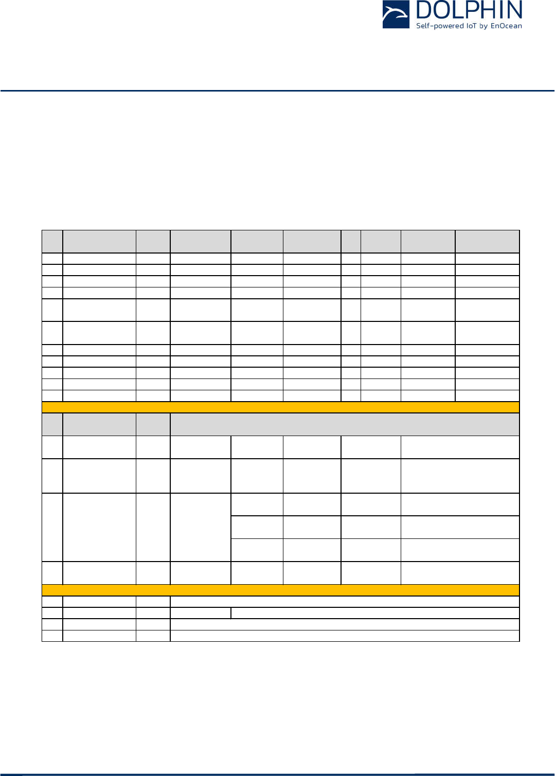
3.7.2 Sensor Status
The Sensor Status field encodes the current status (last reported value) of a sensor.
As described above, the type of the sensor data is identified by the Data Type ID field and
its size is identified by the Data Size field of the preceding Sensor Data Descriptor.
Table 3 below shows the sensor status encoding used by TCM 515B.
Table 3 – Sensor status encoding
ID Type Size
[bytes]
signed Minimum Maximum Unit Encoding
(Input = x)
Measurement
too low
Measurement
Invalid
0x00 Temperature 2 yes -327.67 327.66 °C 100 * x 0x8000 0x7FFF
0x01 Voltage 2 yes -16 383.5 16 383.5 mV 2 * x 0x8000 0x7FFF
0x02 Battery level 1 no 0 126.5 % 2 * x 0xFF 0xFE
0x03 Current 2 yes -32 767 32 766
μ
A x 0x8000 0x7FFF
0x04 Illuminance
(wide angle)
2 no 0 65 533 lx x 0xFFFF 0xFFFE
0x05 Illuminance
(Narrow angle)
2 no 0 65 533 lx x 0xFFFF 0xFFFE
0x06 Relative humidity 1 no 0 126.5 % 2 * x 0xFF 0xFE
0x07 Pressure 2 yes -32 767 32 766 hPa x 0x8000 0x7FFF
0x08 Distance 2 no 0 ~1023.95 cm 64 * x 0xFFFF 0xFFFE
0x09 Gas concentration 2 no 0 32 766.5 ppm 2 * x 0xFFFF 0xFFFE
0x0A Acceleration 2 yes ~-16 ~16 G 2048 * x 0x8000 0x7FFF
ID Type Size
[bytes]
0x20 Occupancy 1 0x00:
Generic Error
0x01:
Not occupied
0x02:
Occupied
0x21 Smoke 1 0x00:
Generic error
0x01:
No smoke
0x02:
Smoke
(ion chamber)
0x01:
Up
0x02:
Right
0x05:
Up to right
0x06:
Right to down
0x09:
Up to left
0x0A:
Left to down
0x23 Open/closed 1 0x00:
Generic error
0x01:
Closed
0x02:
Open
0x3B Device descriptor Variable
0x3C Error report 1 0x00: No error
0x3D User data Variable
0x3E Commissioning 26 Commissioning telegram: 4 byte Sequence Counter + 6 byte Source Address + 16 byte Private Key
Other values: Application specific
All values: Application specific, Size defined by descriptor
All values: Application specific, Size defined by descriptor
Enumerations
System Messages
Enumerated values
0x08:
Left to up
0x07:
Down to left
0x00:
Generic error
0x03:
Standby
0x03:
Smoke
(opt. chamber)
0x03:
Down
0x0B:
Down to right
0x22 Mechanical handle 1
0x04:
Smoke
(both chambers)
0x04:
Left
0x0C:
Right to up
USER MANUAL
TCM 515B – 2.4 GHZ BLUETOOTH LOW ENERGY (BLE) Transceiver
© 2017 EnOcean | www.enocean.com F-710-017, V1.0 TCM 515B User Manual | v0.5 | October 2017 | Page 18/37
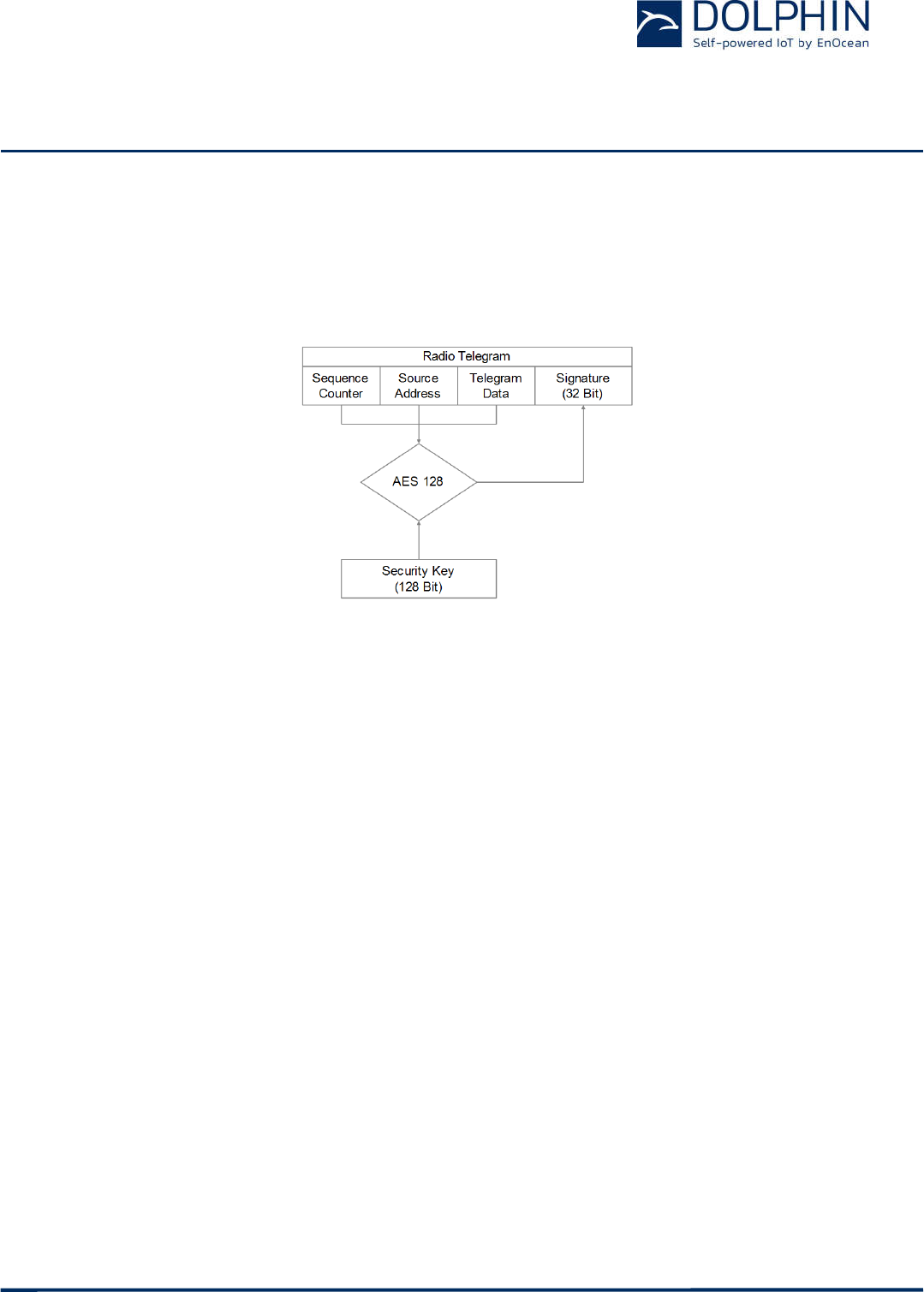
3.8 TCM 515B telegram authentication
TCM 515B implements telegram authentication to ensure that only telegrams from senders
using a previously exchanged security key will be accepted. Authentication relies on a 32
bit telegram signature which is calculated as shown in Figure 12 below and exchanged as
part of the radio telegram.
Figure 12 – Telegram authentication flow
Sequence counter, source address and the remaining telegram data together form the in-
put data for the signature algorithm. This algorithm uses AES128 encryption based on the
device-unique random security key to generate a 32 bit signature which will be transmitted
as part of the radio telegram.
The signature is therefore dependent both on the current value of the sequence counter,
the device source address and the telegram payload. Changing any of these three parame-
ters will therefore result in a different signature.
The receiver performs the same signature calculation based on sequence counter, source
address and the remaining telegram data of the received telegram using the security key it
received from TCM 515B during commissioning.
The receiver then compares the signature reported as part of the telegram with the signa-
ture it has calculated. If these two signatures match then the following statements are
true:
Sender (TCM 515B) and receiver use the same security key
The message content (address, sequence counter, data) has not been modified
At this point, the receiver has validated that the message originates from a trusted sender
(as identified by its security key) and that its content is valid.
In order to avoid message replay (capture and retransmission of a valid message), it is
required that the receiver tracks the value of the sequence counter used by TCM 515B and
only accepts messages with higher sequence counter values (i.e. not accepts equal or lower
sequence counter values for subsequent telegrams).

USER MANUAL
TCM 515B – 2.4 GHZ BLUETOOTH LOW ENERGY (BLE) Transceiver
© 2017 EnOcean | www.enocean.com F-710-017, V1.0 TCM 515B User Manual | v0.5 | October 2017 | Page 19/37
3.9 ESP3 Interface
TCM 515B provides a bi-directional UART interface for communicating with the external
host. The default baud rate of this interface is 57600 bps. If the TURBO pin is set to active
low then the baud rate is increased to 460.800 bps.
3.9.1 ESP3 Data Format
TCM 515B communicate with external hosts using EnOcean Serial Protocol version 3 (ESP3)
with EnOcean 2.4 GHz extensions.
Please consult the detailed ESP3 specification at https://www.enocean.com/esp.
USER MANUAL
TCM 515B – 2.4 GHZ BLUETOOTH LOW ENERGY (BLE) Transceiver
© 2017 EnOcean | www.enocean.com F-710-017, V1.0 TCM 515B User Manual | v0.5 | October 2017 | Page 20/37
4 DEVICE INTEGRATION
TCM 515B is designed for integration onto a host PCB. Detailed Gerber data of the device
footprint is available from EnOcean upon request.
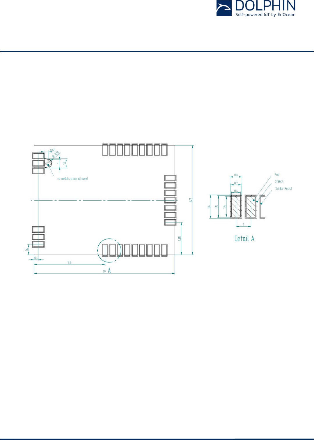
4.1 Recommended PCB Footprint
Figure 13 below shows the recommended PCB footprint for TCM 515B.
Figure 13 – Recommended PCB footprint

USER MANUAL
TCM 515B – 2.4 GHZ BLUETOOTH LOW ENERGY (BLE) Transceiver
© 2017 EnOcean | www.enocean.com F-710-017, V1.0 TCM 515B User Manual | v0.5 | October 2017 | Page 21/37
4.2 Antenna options
This chapter outlines options for antenna that can be used with TCM 515B. Note that this
chapter is for guidance purposes only, please consult with an authorized certification body
for specific information.
4.2.1 General antenna requirements for TCM 515B
Antenna used TCM 515B shall always meet the requirements listed in Fehler! Verweis-
quelle konnte nicht gefunden werden. below.
Frequency band 2.4 GHz ISM Antenna must be suited for this band
Antenna type Passive Mandatory for radio approval
Impedance ~50 Ohm Mandatory for radio approval
Maximum gain ≤ 5 dBi Mandatory for radio approval
Table 4 – General Antenna requirements
4.2.2 Specific antenna requirements for European Union
TCM 515B can be used with the antennas described in subsequent chapters.
See chapter 6 for additional important remarks regarding RED certification.
4.2.3 Specific antenna requirements for US / Canada
The TCM 515B has been tested and certified according to FCC regulation with a number of
different antennas as described below.
4.2.4 Antenna Description
4.2.4.1 Whip Antenna
TCM 515B modules can be used with a whip antenna meeting key parameters shown in
Fehler! Verweisquelle konnte nicht gefunden werden. below.
USER MANUAL
TCM 515B – 2.4 GHZ
BLUETOOTH LOW ENERGY
© 2017 EnOcean | www.enocean.com
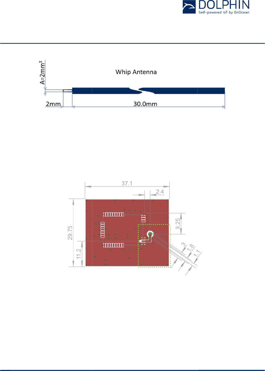
Figure 14 –
Whip antenna with parameters for 2.4 GHz
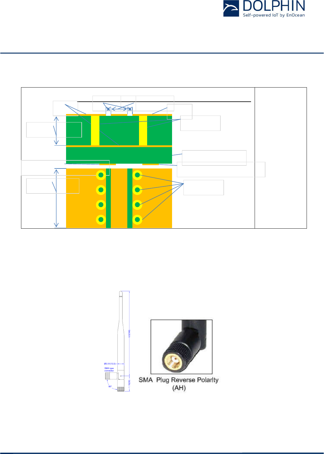
The whip antenna has to meet the following parameters:
Antenna length (L): 30 mm wire, connect to RF_WHIP
Minimum GND plane: 15 mm x 15 mm
Minimum distance space: 10 mm
The referen
ce layout for this antenna is sho
green dotted rectangle and the minimum ground plane has to be implemented exactly as
shown in order to use EnOcean modular approval for US / Canada.
Figure 15 –
Whip antenna
Additionally, the transmission line between TCM 515B and the whip antenna has to be i
plemented as specified in
Figure
/ Canada.
BLUETOOTH LOW ENERGY
(BLE)
Transceiver
F-710-017, V1.0 TCM 515B
User Manual | v
Whip antenna with parameters for 2.4 GHz
The whip antenna has to meet the following parameters:
Antenna length (L): 30 mm wire, connect to RF_WHIP
Minimum GND plane: 15 mm x 15 mm
Minimum distance space: 10 mm
ce layout for this antenna is sho
wn in Figure 15
below. Th
green dotted rectangle and the minimum ground plane has to be implemented exactly as
shown in order to use EnOcean modular approval for US / Canada.
Whip antenna
reference layout
Additionally, the transmission line between TCM 515B and the whip antenna has to be i
Figure
16 below
in order to use EnOcean modular approval for US
Transceiver
User Manual | v
0.5 | October 2017 | Page 22/37
Whip antenna with parameters for 2.4 GHz
below. Th
e area within the
green dotted rectangle and the minimum ground plane has to be implemented exactly as
Additionally, the transmission line between TCM 515B and the whip antenna has to be i
m-
in order to use EnOcean modular approval for US
USER MANUAL
TCM 515B – 2.4 GHZ BLUETOOTH LOW ENERGY (BLE) Transceiver
© 2017 EnOcean | www.enocean.com F-710-017, V1.0 TCM 515B User Manual | v0.5 | October 2017 | Page 23/37
w = 1.00mm
s = 0.15mm
h =
0.90…2.00m
m
(see
Note 1)
Typical line
impedance
on
FR4=44…56
Ω
Return
loss>=24dB
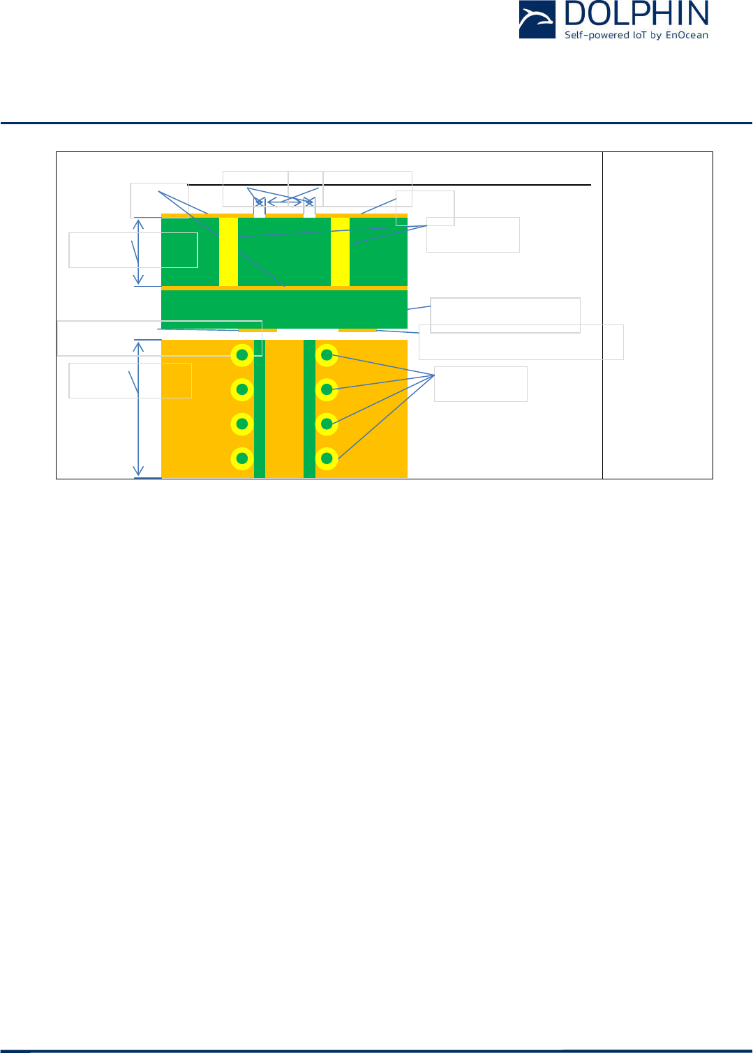
Figure 16 – Transmission line specification
Note (1): Coplanar waveguide modes are dominant in this configuration. Thus thickness of
substrate can be changed with the given limits.
4.2.4.2 Meandered PCB Antenna
TCM 515B has been certified for use with a meandered PCB antenna provided that the fol-
lowing layout guidelines are met:
Matching circuit values of the modular approval may not be changed, use matching
circuit components as specified in Table 5
Shape according to reference layout in Figure 17
Minimum GND plane: 40 mm x 18 mm
Connect GND planes using multiple via as shown in Figure 17
Minimum distance space: 10 mm
PCB Stack of the modular approval may not be changed,
use PCB stack as specified in Figure 18 – PCB stack specification for meandered PCB
antenna
Side View
Top View
Grounded Coplanar Waveguide (GCPW)
Line heigth: h
line gap: s
line width: w
Line length: l
GND
GND
optional layer(s)
other signals (optional)
other signals (optional)
GND vias
GND vias
USER MANUAL
TCM 515B – 2.4 GHZ
BLUETOOTH LOW ENERGY
© 2017 EnOcean | www.enocean.com
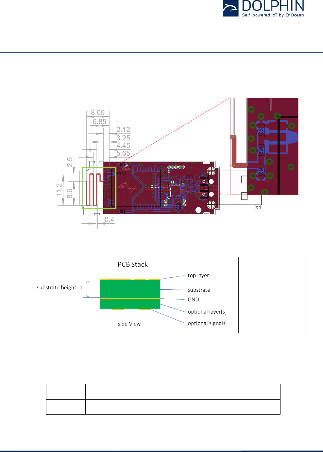
Figure 17 below shows
the dimensions of the meandered PCB antenna, the matching circuit
and the area important for US / Canada modular approval (marked in green).
Figure 17 –
Reference layout for meandered PCB antenna
Figure 18 –
PCB stack specification for meandered PCB antenna
Table 5 below lists the
parameters of the
strate with 1.0 mm height.
It is mandatory to not change the designator values and su
strate height for compliance with
Designator
Value
C8 1.0pF
R9 6.8nH
C9 ---
Table 5 – Parameters
of the matching circuit
BLUETOOTH LOW ENERGY
(BLE)
Transceiver
F-710-017, V1.0 TCM 515B
User Manual | v
the dimensions of the meandered PCB antenna, the matching circuit
and the area important for US / Canada modular approval (marked in green).
Reference layout for meandered PCB antenna
PCB stack specification for meandered PCB antenna
parameters of the
matching circuit
components
It is mandatory to not change the designator values and su
strate height for compliance with US / Canada modular approval usage.
Notes
Use Murata GRM1555 series or similar
Use Würth WE-
KI series, Murata LQW series or similar
Not assembled
of the matching circuit
for 1.0 mm substrate height
Transceiver
User Manual | v
0.5 | October 2017 | Page 24/37
the dimensions of the meandered PCB antenna, the matching circuit
and the area important for US / Canada modular approval (marked in green).
h = 1.00mm
substrate: FR4
components
using a FR4 sub-
It is mandatory to not change the designator values and su
b-
US / Canada modular approval usage.
KI series, Murata LQW series or similar
for 1.0 mm substrate height
USER MANUAL
TCM 515B – 2.4 GHZ BLUETOOTH LOW ENERGY (BLE) Transceiver
© 2017 EnOcean | www.enocean.com F-710-017, V1.0 TCM 515B User Manual | v0.5 | October 2017 | Page 25/37
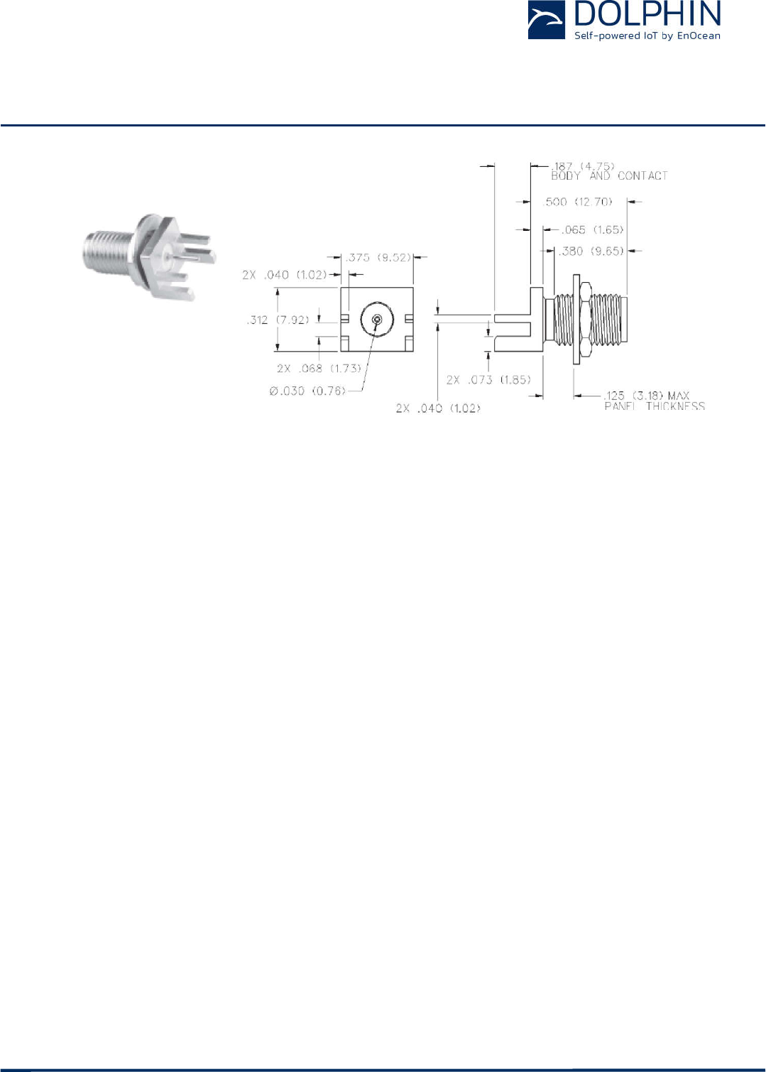
4.2.4.3 Dipole antenna requirements
The TCM 515B has been certified for use with the dipole antenna model S151AH-2450S
from Nearson or other antennas with similar parameters provided that:
The RF connector is a non-standard connector such as a RP-SMA-Female from John-
son/Cinch Connectivity Solutions (142-4701-801)
In addition, the following layout guidelines have to be met:
The bottom GND plane is implemented below the RF transmission line section of the
circuit to form a grounded coplanar waveguide (Figure 20 – Detailed description
of RF transmission line)
The ground planes have to be connected using multiple via along RF transmission
line as shown in Figure 19 and Figure 20
Table 6 at the end of this section lists dipole antennas that can be used optional instead of
S151AH-2450S antenna stated previously as they are of the same kind with less or equal
gain.
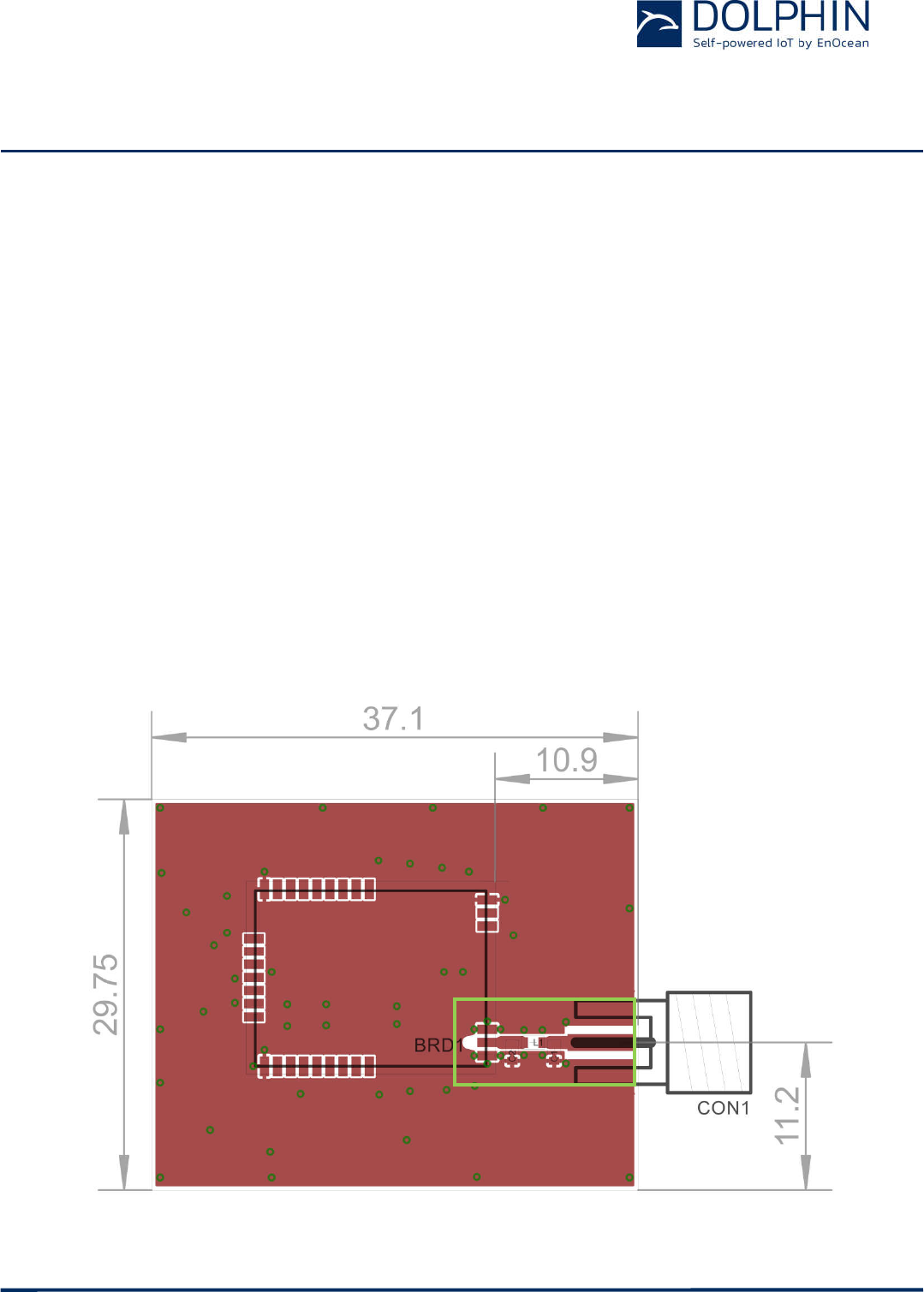
Figure 19 below shows the layout used for compliance tests. The section of the layout lo-
cated within the green frame has to remain unchanged for US / Canada modular approval
usage.
Figure 19 – Reference layout for dipole antenna
USER MANUAL
TCM 515B – 2.4 GHZ BLUETOOTH LOW ENERGY (BLE) Transceiver
© 2017 EnOcean | www.enocean.com F-710-017, V1.0 TCM 515B User Manual | v0.5 | October 2017 | Page 26/37
The transmission line between TCM 515B and the antenna has to be implemented as shown
in the following picture (Figure 20).
w =1.00mm
s = 0.15mm
h
=0.90…2.00m
m
(see Note
1)
Typical line
impedance on
FR4=44…56Ω
Return
loss>=24dB
Figure 20 – Detailed description of RF transmission line
Note (1): Coplanar waveguide modes are dominant in this configuration. Thus thickness of
substrate can be changed with the given limits.
Figure 21 below shows dipole antenna model S151AH-2450S from Nearson that was used
for certification tests.
Figure 21 – dipole antenna model S151AH-2450S
Side View
Top View
Grounded Coplanar Waveguide (GCPW)
Line heigth: h
line gap: s
line width: w
Line length: l
GND GND
optional layer(s)
other signals (optional)
other signals (optional)
GND vias
GND vias
USER MANUAL
TCM 515B – 2.4 GHZ BLUETOOTH LOW ENERGY (BLE) Transceiver
© 2017 EnOcean | www.enocean.com F-710-017, V1.0 TCM 515B User Manual | v0.5 | October 2017 | Page 27/37
Figure 22 – RP-SMA-Female
Figure 22 above displays the RP-SMA-Female (142-4701-801) from Chinch Connectivity
Solutions as an example for a non-standard RF connector required for US / Canada modular
approval usage.

USER MANUAL
TCM 515B – 2.4 GHZ BLUETOOTH LOW ENERGY (BLE) Transceiver
© 2017 EnOcean | www.enocean.com F-710-017, V1.0 TCM 515B User Manual | v0.5 | October 2017 | Page 28/37
Table 6 gives a list of examples of dipole antennas that could be used with TCM 5151B un-
der US / Canada modular approval.
Manufacturer Manufacturer Part Number Gain Antenna Type
Nearson Inc.
1
S151AH-2450S 5dBi Whip (Dipole), Tilt
Nearson Inc. S131AH-2450S 5dBi Whip (Dipole), Tilt
Nearson Inc. S181AH-2450S 2dBi Whip (Dipole), Tilt
ATOP Technologies ANT-WS-AB-RM-05-200 5dBi Whip (Dipole), Straight
ATOP Technologies ANT-WS-AB-RM-05-180 5dBi Whip (Dipole), Straight
Digi International A24-HASM-525 2.1dBi
Whip (Dipole), Tilt
Digi International A24-HASM-450 2.1dBi
Whip (Dipole), Tilt
Digi International DG-ANT-20DP-BG 2dBi Whip (Dipole), Tilt
Digi International DC-ANT-24DP 1.8dBi
Whip (Dipole), Tilt
Digi International DC-ANT-24DT 1.8dBi
Whip (Dipole), Straight
Honeywell WAN01RSP 2.2dBi
Whip (Dipole), Straight
Honeywell WAN02RSP 2.2dBi
Whip (Dipole), Tilt
Laird Technologies IAS S2403BH36RSM 3dBi Whip (Dipole), Straight
Laird Technologies IAS EXR2400RSM 3dBi Whip (Dipole), Tilt
Laird Technologies IAS MAF94046 1.3dBi
Whip (Dipole), Tilt
Laird Technologies IAS MAF94028 1.3dBi
Whip (Dipole), Tilt
Laird Technologies IAS MAF94112 1.5dBi
Whip (Dipole), Tilt
Linx Technologies Inc. ANT-2.4-CW-HW 3.2dBi
Whip (Dipole), Straight
Linx Technologies Inc. ANT-2.4-CW-RCT-RP 2.2dBi
Whip (Dipole), Tilt
Linx Technologies Inc. ANT-2.4-CW-HWR-RPS 3.2dBi
Whip (Dipole), Tilt
Linx Technologies Inc. ANT-2.4-CW-CT-RPS 2.8dBi
Whip (Dipole), Straight
LSR 001-0010 2dBi Whip (Dipole), Tilt
LSR 001-0001 2dBi Whip (Dipole), Tilt
Microchip Technology RN-SMA4-RP 2.2dBi
Whip (Dipole), Tilt
Proant AB 333 3dBi Whip (Dipole), Tilt
Proant AB 348 3dBi Whip (Dipole), Straight
Pulse Electronics W1037 3.2dBi
Whip (Dipole), Tilt
Pulse Electronics W1027 3.2dBi
Whip (Dipole), Tilt
Pulse Electronics W1030 2dBi Whip (Dipole), Tilt
Pulse Electronics W5010 1.5dBi
Whip (Dipole), Straight
Pulse Electronics W5001 1.5dBi
Whip (Dipole), Right Angle
Red Lion Controls ANT-GW11A153 2.3dBi
Whip (Dipole), Tilt
Siretta Ltd DELTA6B/X/SMAM/RP/S/11 5dBi Whip (Dipole), Tilt
Siretta Ltd DELTA10A/X/SMAM/RP/S/17
3dBi Whip (Dipole), Straight
Taoglas Limited GW.11.A153 2.3dBi
Whip (Dipole), Tilt
Taoglas Limited GW.26.0151 1.8dBi
Whip (Dipole), Straight
Walsin Technology RFDPA151300SBAB8G1 3dBi Whip (Dipole), Tilt
Walsin Technology RFDPA171300SBAB8G1 3dBi Whip (Dipole), Tilt
Walsin Technology RFDPA870900SBAB8G1 2dBi Whip (Dipole), Tilt
Table 6 – Dipole antenna options
1 antenna tested for FCC and IC certification
USER MANUAL
TCM 515B – 2.4 GHZ BLUETOOTH LOW ENERGY (BLE) Transceiver
© 2017 EnOcean | www.enocean.com F-710-017, V1.0 TCM 515B User Manual | v0.5 | October 2017 | Page 29/37
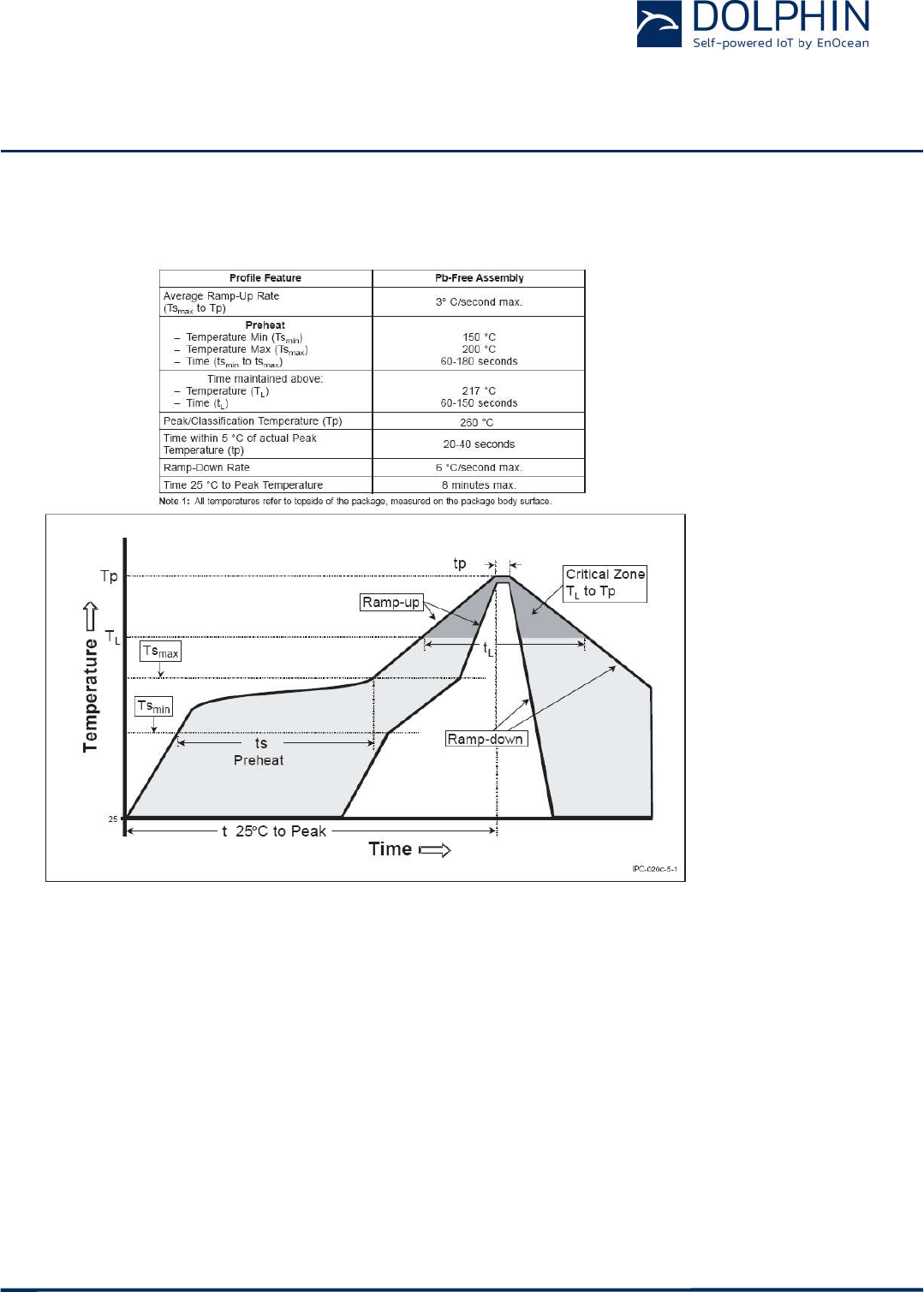
4.3 Soldering information
TCM 515B has to be soldered according to IPC/JEDEC J-STD-020C standard as outlined in
Figure 23 below.
Figure 23 – Recommended temperature profile
4.4 Device handling instructions
TCM 515B shall be handled according to Moisture Sensitivity Level MSL 3. TCM 515B may
be soldered only once, since one time is already consumed at production of the module
itself.
Once the dry pack bag is opened, the desired quantity of units should be removed and the
bag resealed within two hours. If the bag is left open longer than 30 minutes the desiccant
should be replaced with dry desiccant. If devices have exceeded the specified floor life time
of 168 h, they may be baked according IPC/JEDEC J-STD-033B at max. 90 °C for less than
60 h.
Devices packaged in moisture-proof packaging should be stored in ambient conditions not
exceeding temperatures of 40 °C or humidity levels of 90% r.H.
TCM 515B modules have to be soldered within 6 months after delivery!

USER MANUAL
TCM 515B – 2.4 GHZ BLUETOOTH LOW ENERGY (BLE) Transceiver
© 2017 EnOcean | www.enocean.com F-710-017, V1.0 TCM 515B User Manual | v0.5 | October 2017 | Page 30/37
In general we recommend a no clean flux process. If washing is needed, then TCM 515B
radio modules have a shield cover with small openings at the top of the edges.
It is very important to mount the modules in a top down position during the drying process
as this will allow getting the aggregated washing fluid removed properly from within the
shield cover area.
To prevent damage, modules have to be checked for any remaining fluid after the drying.
4.5 Device operation instructions
TCM 515B shall only be operated while assembled onto a PCB that is integrated into a suit-
able product housing.
TCM 515B shall only be supplied using “Limited Power Sources” compliant with EN 62368-1
clause 6.2.2.4 and a maximum output power of 15W (PS1).
USER MANUAL
TCM 515B – 2.4 GHZ BLUETOOTH LOW ENERGY (BLE) Transceiver
© 2017 EnOcean | www.enocean.com F-710-017, V1.0 TCM 515B User Manual | v0.5 | October 2017 | Page 31/37
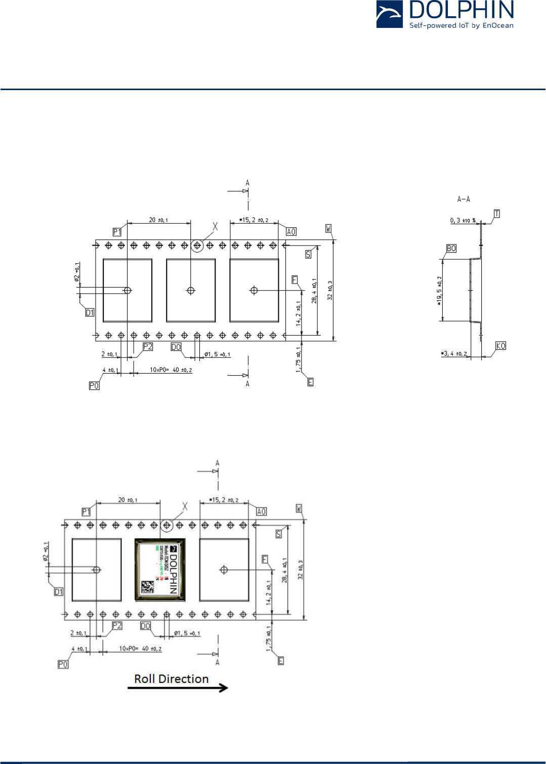
4.6 Tape & Reel specification
TCM 515B is delivered in Tape & Reel packaging with 250 units per reel. Figure 24 below
illustrates the dimensions.
Figure 24 – Tape & Reel dimensions of TCM 515B
Figure 25 below shows the positioning of TCM 515B in the Tape & Reel packaging.
Figure 25 – Position of TCM 515B in the reel

USER MANUAL
TCM 515B – 2.4 GHZ BLUETOOTH LOW ENERGY (BLE) Transceiver
© 2017 EnOcean | www.enocean.com F-710-017, V1.0 TCM 515B User Manual | v0.5 | October 2017 | Page 32/37
5 APPLICATION INFORMATION
5.1 Transmission range
The main factors that influence the system transmission range are:
- Type and location of the antennas of receiver and transmitter
- Type of terrain and degree of obstruction of the link path
- Sources of interference affecting the receiver
- “Dead spots” caused by signal reflections from nearby conductive objects.
Since the expected transmission range strongly depends on this system conditions, range
tests should always be performed to determine the reliably achievable range under the
given conditions.
The following figures should be treated as a rough guide only:
- Line-of-sight connections
Typically 10 m range in corridors, up to 50 m in halls
- Plasterboard walls / dry wood
Typically 10 m range, through max. 2 walls
- Ferro concrete walls / ceilings
Maximum 1 wall or ceiling, depending on thickness and material
- Fire-safety walls, elevator shafts, staircases and similar areas should be considered
as shielded
The angle at which the transmitted signal hits the wall is very important. The effective wall
thickness – and with it the signal attenuation – varies according to this angle. Signals
should be transmitted as directly as possible through the wall. Wall niches should be
avoided.
Other factors restricting transmission range include:
- Switch mounting on metal surfaces (up to 30% loss of transmission range)
- Hollow lightweight walls filled with insulating wool on metal foil
- False ceilings with panels of metal or carbon fibre
- Lead glass or glass with metal coating, steel furniture
The distance between the receiver and other transmitting devices such as computers, audio
and video equipment that also emit high-frequency signals should be at least 0.5 m.

USER MANUAL
TCM 515B – 2.4 GHZ BLUETOOTH LOW ENERGY (BLE) Transceiver
© 2017 EnOcean | www.enocean.com F-710-017, V1.0 TCM 515B User Manual | v0.5 | October 2017 | Page 33/37
6 REGULATORY INFORMATION
TCM 515B has been tested according to CE regulation. Changes or modifications not ex-
pressly approved by EnOcean could void compliance with RED requirements.
6.1 CE (RED) for European Union
According to laws of the member states of the European Union OEM manufacturer or dis-
tributor are responsible for the conformity of the product. Note the following requirements
for CE certification:
The existing R&TTE directive has been replaced by RED (radio equipment directive) since
13th of June 2016.
OEM manufacturers or distributors which sell this component as a product to his (final) cus-
tomers have to fulfill all requirements of the radio equipment directive (RED).
RED contains at least following requirements for OEM manufacturers or distributors:
Provide product branding (on the product) clearly identifying company name or
brand and product name as well as type, charge or serial number for market surveil-
lance
Include (with the product) documentation containing full postal address of the man-
ufacturer as well as radio frequency band and max. transmitting power
Include (with the product) user manual, safety information and a declaration of con-
formity for the final product in local language
Provide product development and test documentation upon request
OEM has to fulfill all additional requirements according to RED such as market sur-
veillance or 10 years record retention.
For details and national translations, please see:
http://eur-lex.europa.eu/legal-content/EN/TXT/?uri=celex:32014L0053

USER MANUAL
TCM 515B – 2.4 GHZ BLUETOOTH LOW ENERGY (BLE) Transceiver
© 2017 EnOcean | www.enocean.com F-710-017, V1.0 TCM 515B User Manual | v0.5 | October 2017 | Page 34/37
6.2 FCC (United States) Certificate
< to be inserted>

USER MANUAL
TCM 515B – 2.4 GHZ BLUETOOTH LOW ENERGY (BLE) Transceiver
© 2017 EnOcean | www.enocean.com F-710-017, V1.0 TCM 515B User Manual | v0.5 | October 2017 | Page 35/37
6.2.1 FCC (United States) regulatory statement
This device complies with part 15 of the FCC Rules. Operation is subject to the following
two conditions:
(1) this device may not cause harmful interference, and
(2) this device must accept any interference received, including interference that may
cause undesired operation.
6.2.2 FCC (United States) labeling requirements
This module is labeled with its own FCC ID number, and, if the FCC ID is not visible when
this module is installed inside another device, then the outside of this device into which the
module is installed must also display a label referring to this enclosed module.
This exterior label can use wording such as the following:
"Contains Transmitter Module FCC ID: SVZ-TCM515B"
Or alternatively:
"Contains FCC ID: SVZ-TCM515B"
Any similar wording that expresses the same meaning may be used. Figure 26 below shows
an example of such label.
Figure 26 – Label example
6.2.3 FCC (United States) RF exposure statement
This module complies with radiofrequency radiation exposure limits according to 47 CFR, §
2.1093, applying general RF exclusion guidance KDB 447498.
Calculation of conducted output power:
conducted output power: 4.5 dBm
duty cycle correction factor: -14 dBm
time averaged output power: -9.5 dBm
time averaged output power: 0.1 mW
FCC output power exception limit: . ( )∗
√(())
Frequency f: 2.4 GHz
Limit: 10 mW
Contains FCC ID: SVZ-TCM515B

USER MANUAL
TCM 515B – 2.4 GHZ BLUETOOTH LOW ENERGY (BLE) Transceiver
© 2017 EnOcean | www.enocean.com F-710-017, V1.0 TCM 515B User Manual | v0.5 | October 2017 | Page 36/37
6.3 ISED (Industry Canada) Technical Acceptance Certificate
< to be inserted>

USER MANUAL
TCM 515B – 2.4 GHZ BLUETOOTH LOW ENERGY (BLE) Transceiver
© 2017 EnOcean | www.enocean.com F-710-017, V1.0 TCM 515B User Manual | v0.5 | October 2017 | Page 37/37
6.3.1 ISED (Industry Canada) regulatory statement
This device complies with Industry Canada license-exempt RSS standard(s).
Operation is subject to the following two conditions:
(1) this device may not cause interference, and
(2) this device must accept any interference, including interference that may cause unde-
sired operation of the device.
Le présent appareil est conforme aux CNR d'Industrie Canada applicables aux appareils
radio exempts de licence.
L'exploitation est autorisée aux deux conditions suivantes :
(1) l'appareil ne doit pas produire de brouillage, et
(2) l'utilisateur de l'appareil doit accepter tout brouillage radioélectrique subi, même si le
brouillage est susceptible d'en compromettre le fonctionnement.”
6.3.2 ISED (Industry Canada) RF exposure statement
This module complies with the Exemption Limits for Routine Evaluation of radiofrequency
radiation exposure according to RSS-102, 2.5.1.
Calculation of e.i.r.p. (effective isotropic radiated power):
conducted output power: 4.5 dBm
maximum gain of antenna: 5.0 dBi
maximum e.i.r.p.: 9.5 dBm
duty cycle correction factor -14 dBm
time averaged e.i.r.p -4.5 dBm
time averaged e.i.r.p 0.4 mW
ISED Exeption limit for time-averaged e.i.r.p output power
Frequency f: 2450 MHz
Limit 4 mW
Source: https://www.ic.gc.ca/eic/site/smt-gst.nsf/vwapj/rss-102-issue5.pdf/$file/rss-102-issue5.pdf