Enlighted SU4S Intelligent Light Sensor for Smart Networked Energy Saving Light Systems using 802.15.4 protocol stack and BLE for communications. User Manual PowerPoint Presentation
Enlighted, Inc. Intelligent Light Sensor for Smart Networked Energy Saving Light Systems using 802.15.4 protocol stack and BLE for communications. PowerPoint Presentation
Contents
- 1. Users Mnual
- 2. Users Manual
Users Manual
Page 5 Page 6 93-01663-01 Rev01 Page 1
Copyright © 2016 Enlighted Inc. All rights reserved.
All other brand or product names are trademarks of
their respective companies or organizations.
TechnicalSupport
For questions regardingthe installation or operation of
this product, contact Enlighted
Technical Support: support@enlightedinc.com
Company Contact Information
Location: 930 Benecia Ave, Sunnyvale, CA 94085
Phone: +1.650.964.1094
Web: enlightedinc.com
FCC and Industry Canada Compliance Information
This equipment has been tested and found to comply with the limits
for a Class A digital device, pursuant to part 15 of the FCC Rules.
These limits are designed to provide reasonable protection against
harmful interference when the equipment is operated in a
commercial environment. This equipment generates, uses, and can
radiate radio frequency energy and, if not installed and used in
accordance with the instruction manual, may cause harmful
interference to radio communications. Operation of this equipment
in a residential area is likely to cause harmful interference in which
case the user will be required to correct the interference at his own
expense.
This device complies with Part 15 of the FCC Rules and Industry
Canada license-exempt RSS standard(s). Operation is subject to the
following two conditions:
•this device may not cause harmful interference, AND
•this device must accept any interference received, including
interference that may cause undesired operation.
Changes or modifications not expressly approved by Enlighted Inc.
could void the user's authority to operate the equipment.
Le présent appareil est conforme aux CNR d'Industrie Canada
applicables aux appareils radio exempts de licence. L'exploitation
est autorisée aux deux conditions suivantes:
•l'appareil ne doit pas produire de brouillage, ET
•l'utilisateur de l'appareil doit accepter tout brouillage
radioélectrique subi, même si le brouillage est susceptible d'en
compromettre le fonctionnement.
CE
This device complies with the essential requirements and other
relevant requirements of the R&TTE Directive (1999/5/EC). The
equipment is Class 1 radio equipment which can be placed on the
market and be put into service without restrictions in accordance
with article 1(3) of Commission Decision 2000/299/EC (Version July
2014).
Ruggedized Sensor
(SU-4S)
Installation Instructions
Model: SU-4S
FCC ID: AQQ-SU4S
IC: 10138A-SU4S
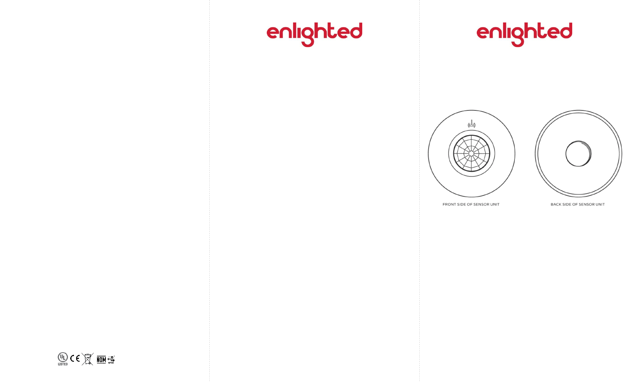
Ruggedized Sensor (front and back)
Applicable For:
SU-4S-LRW; SU-4S-LRB
SU-4S-HRW; SU-4S-HRB
Shipped Components
Enlighted Ruggedized Sensor Unit
½ inch Lock Nut
Tools you may Need
½ inch Knock out tool
Items you will Need
½ inch LB Conduit Body
½ inch Chase Nipple
Page 2 Page 3 Page 4
Installation
Figure 7
The Ruggedized sensor is shipped with the cable attached to the
sensor. Figure 1.
Figure 1
Figure 6
LED Status Description/Solution
LED not on Check power and wiring
Purple solid All LEDs are on during boot time for 5-6
seconds
Green blinking Sensor commissioned and working
Red blinking Incompatibility between LED driver and sensor
–Replace LED driver and if not resolved,
replace sensor.
Red solid Faulty sensor –replace sensor
Green solid Sensor installed, initialized, and
uncommissioned –waiting for discovery.
Blue solid Image being upgraded.
LED Description
Caution
Installation and maintenance must be performed by a qualified
electrician in accordance with local, state, and national electrical
codes (NEC) and requirements.
Step 1: Turn off all power to the light fixture by switching off
the circuit breaker.
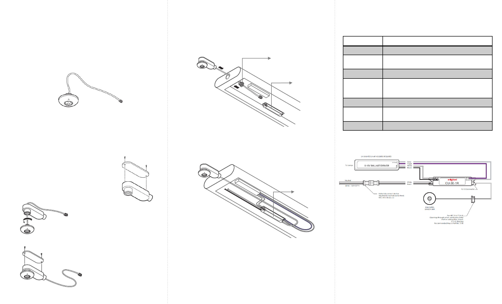
Step 2: Mount the Control Unit (CU) in a UL approved
enclosure. Refer to the Control Unit Installation Guide. See
Figure 7 for detailed wiring connections from the CU.
Step 3: Remove the cover plate of the
½ inch LB conduit body by removing
the two screws. Figure 2.
Figure 2
Step 4: Thread the Ruggedized
sensor onto LB conduit body.
Figure 3.
Figure 4
Step 6: Knock out a ½ inch hole on the end of the light
fixture. Using the ½ inch chase nipple, connect the LB
conduit to the fixture. See Figure 5.
Step 5: Replace the cover and two
screws on the LB conduit body.
Figure 4.
Figure 3
Figure 5
Chase Nipple
Step 7: Pull the Ruggedized sensor cable through the chase
nipple into the fixture and connect it to the Control Unit.
See Figure 6. For wiring connections to the CU, see Figure 7.
Step 8: If the ruggedized senor cable is not long enough to
reach the Control Unit, use an RJ12 coupling to connect
the rugged sensor cable to an Enlighted 7ft Sensor cable.
(CBL-2-7F)
Step 9: Switch on the circuit breaker to turn the power on.
Enlighted
Control Unit
Enlighted
Control Unit