Ensemble Communications ODU-2800-001 Fiberless 2800 Series Outdoor Unit transceiver User Manual Users manual 3 of 3 IDU Install

Ensemble Communications Inc. Fiberless 2800 Series Outdoor Unit transceiver Users manual 3 of 3 IDU Install

Users manual 3 of 3 IDU Install
Ensemble Communications Inc.CPE Site Setup 6-CPE Indoor InstallationIndoor EquipmentPlacementThe Fiberless 320 CPE can be located in a wiring closet with other communications equipment or in a customer suite. Its compact low-profile package, rubber feet, and optional mounting brackets make it easy to mount it in either a standard 19-inch or 23-inch cabinet or stack on a shelf. CPE Indoor AccessRequirementAllow enough room to accommodate the size of the unit (1.5 inches high by 9.5 inches deep) with enough clearance to accommodate termination of up to 16 data cables or 12 T1 cables, two cables to the ODU, and a power cord. CPE IndoorTemperatureThe location should meet these temperature allowances, including enough ventilation to dissipate heat loads of 150 Watts:10° to 30° C (50° to 86° F)CPE Indoor Power The CPE indoor unit is normally shipped for use with 120 VAC power. When possible, it should be plugged into a dedicated 15 Amp circuit. You may install a small PC-style UPS if desired.CPE Indoor Grounding For AC systems, ground the indoor unit by connecting its conductor to a grounded power outlet. The ground conductor on the power plug must be connected to the building’s electrical ground. WARNINGDo not power up the indoor unit until you are instructed to do so during the initial procedure.CPE Indoor Procedure •Select an environment that is dirt and dust free for the CPE. •Situate the CPE box in a rack, shelf mount or on a table top. Connect the power cable to the power connector on the back of the CPE indoor equipment.
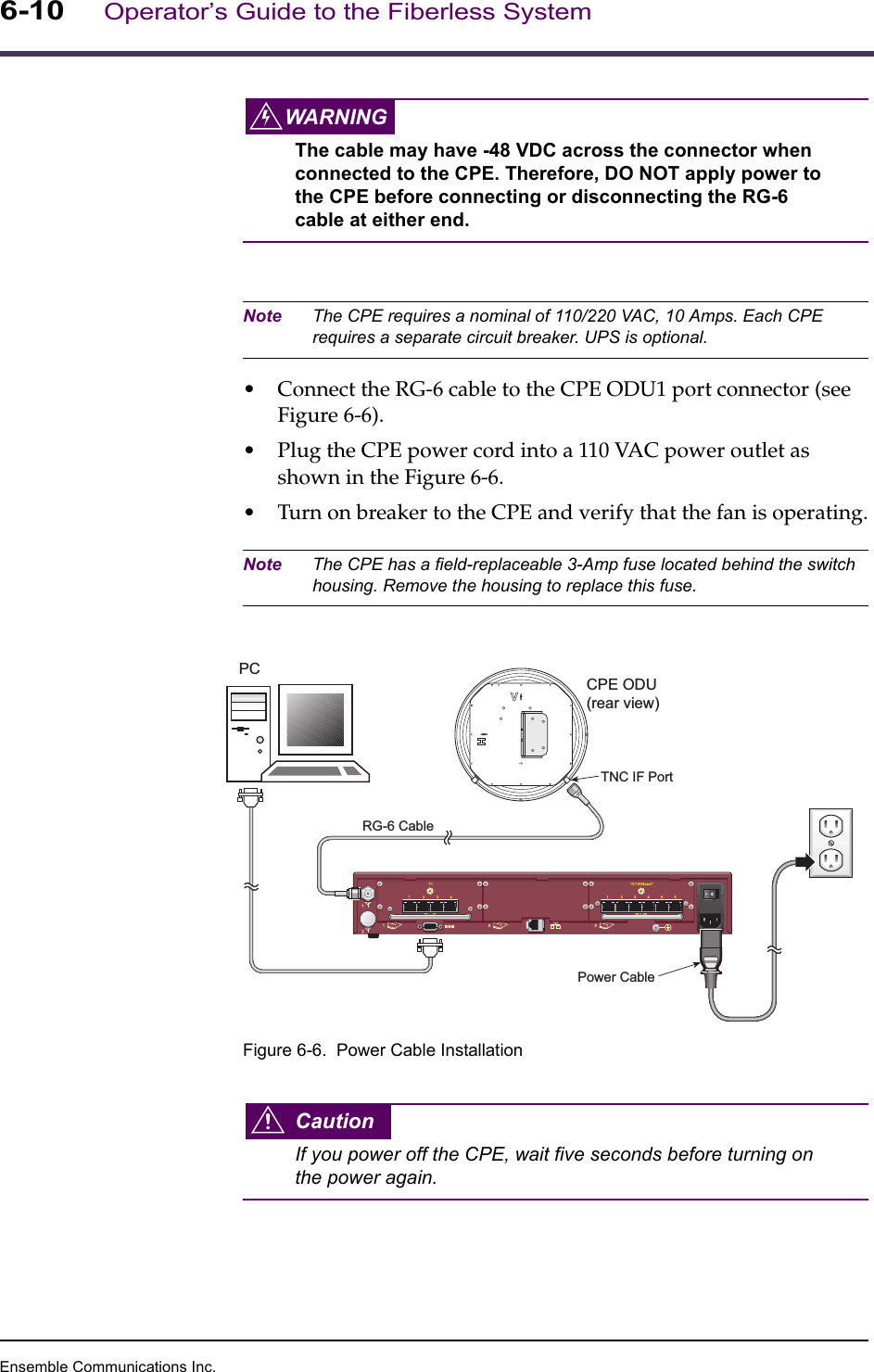
Ensemble Communications Inc.6-10Operator’s Guide to the Fiberless SystemWARNINGThe cable may have -48 VDC across the connector when connected to the CPE. Therefore, DO NOT apply power to the CPE before connecting or disconnecting the RG-6 cable at either end. Note The CPE requires a nominal of 110/220 VAC, 10 Amps. Each CPE requires a separate circuit breaker. UPS is optional.•Connect the RG-6 cable to the CPE ODU1 port connector (see Figure 6-6).•Plug the CPE power cord into a 110 VAC power outlet as shown in the Figure 6-6.•Turn on breaker to the CPE and verify that the fan is operating.Note The CPE has a field-replaceable 3-Amp fuse located behind the switch housing. Remove the housing to replace this fuse.Figure 6-6.  Power Cable InstallationCautionIf you power off the CPE, wait five seconds before turning on the power again.SICRG-6 CablePower CableCPE ODU(rear view)TNC IF PortPC

Navigation menu