Escort Data Logging Systems MINI PORTABLE DATA LOGGING DEVICE User Manual Wireless Mini technical manual v1 3
Escort Data Logging Systems Ltd PORTABLE DATA LOGGING DEVICE Wireless Mini technical manual v1 3
Contents
- 1. USERS MANUAL
- 2. TECHNICAL MANUAL
- 3. QUICK REFERENCE GUIDE
USERS MANUAL
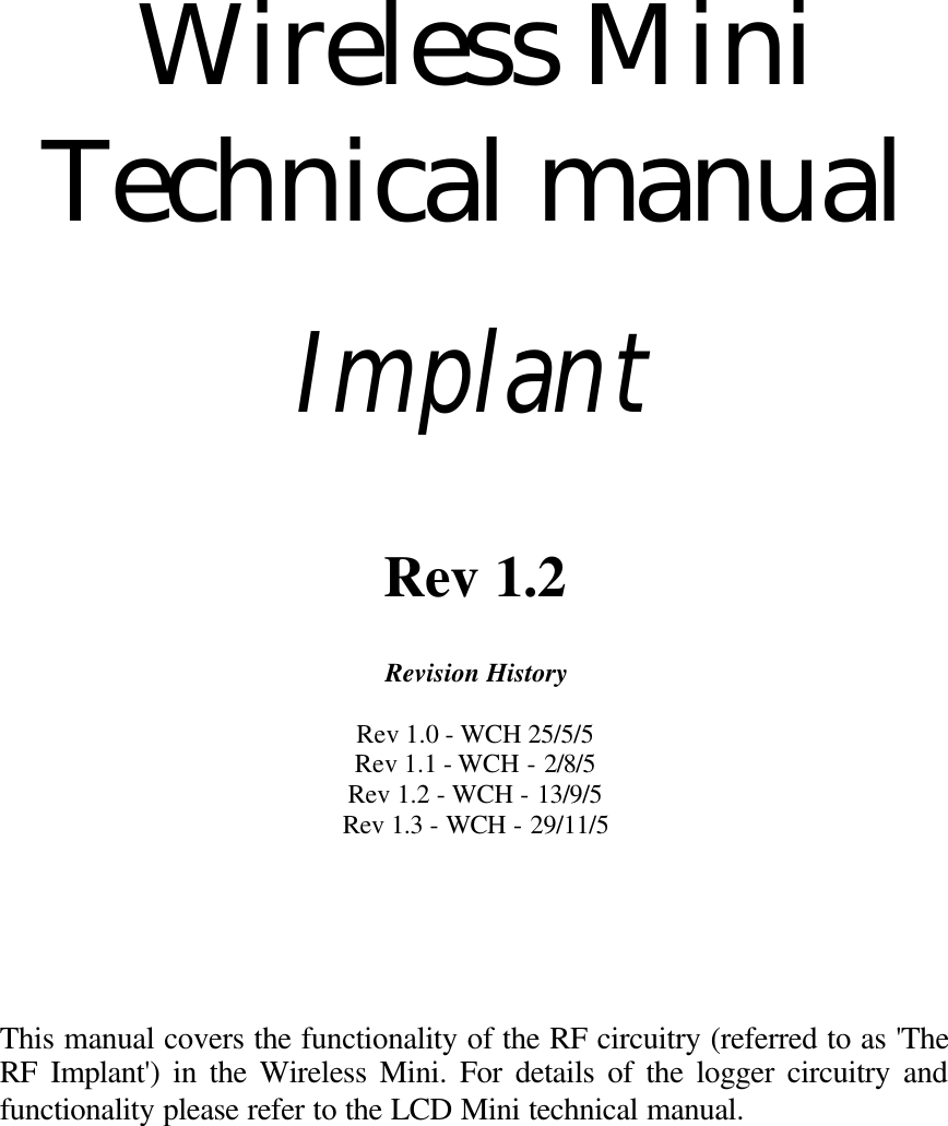


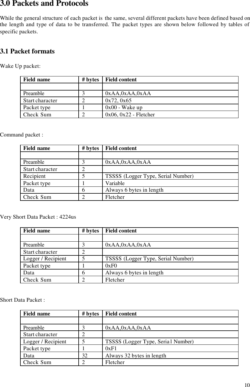
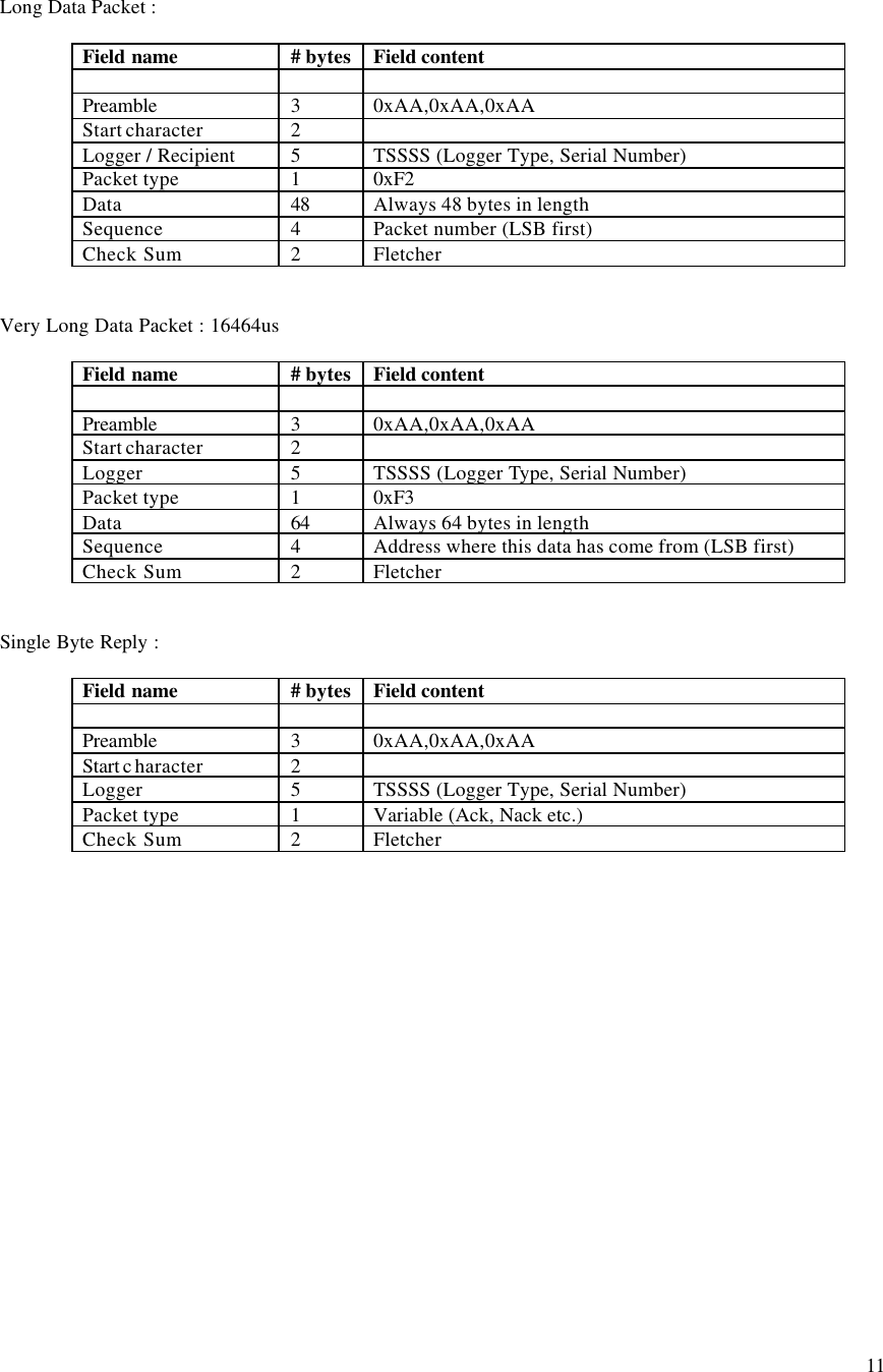
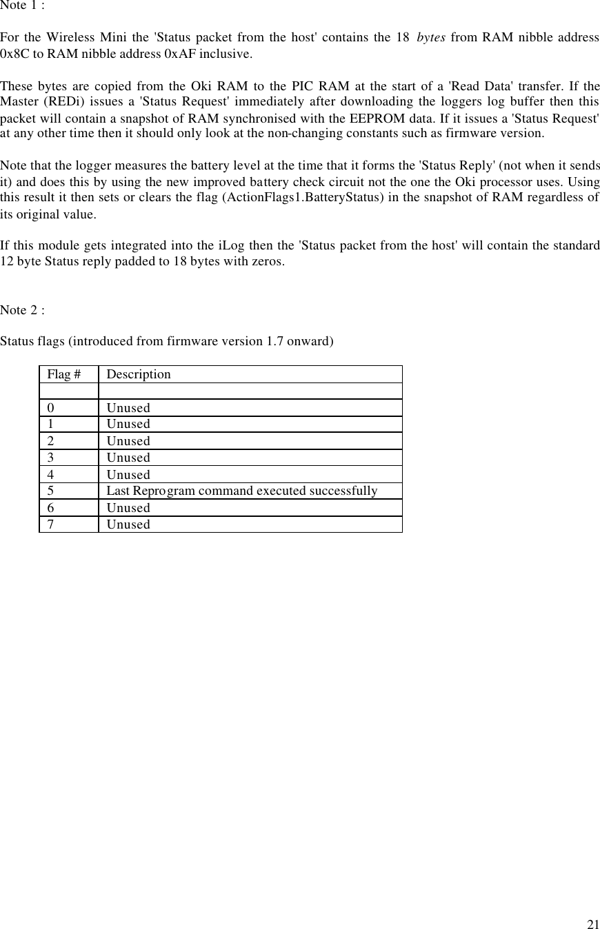
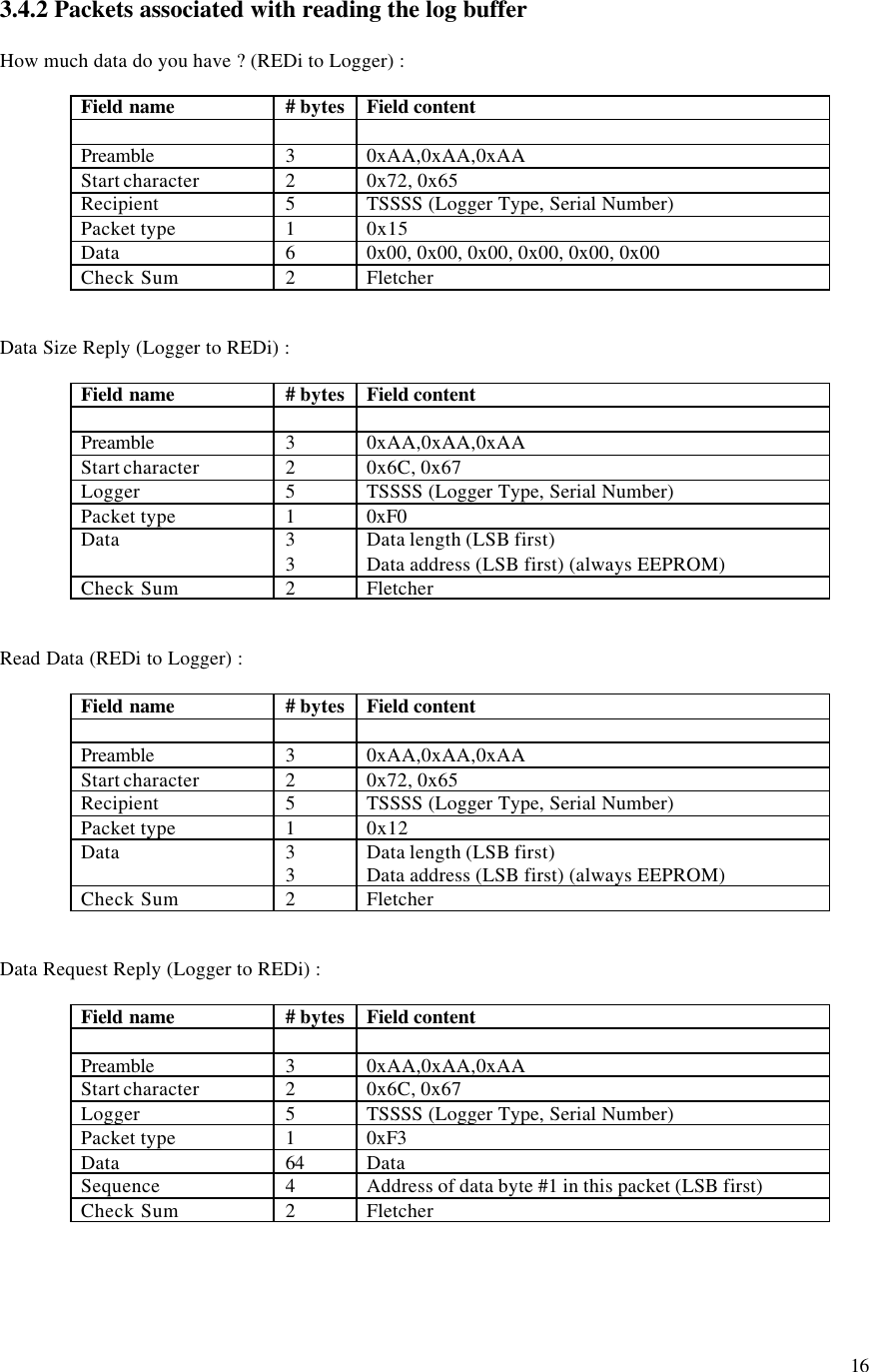
![12 3.2 Specific packet types REDi to Logger Name Packet ID (PType) Packet Type Recipient Data Description Wake Up 0x00 Wake up Non specific none Broadcast over and over for 1 second to wake up all loggers. Ack 0x01 Single Byte Reply TT,SN,SN,SN,SN none Acknowledgement of correct reception of a packet. Resend 0x02 Single Byte Reply TT,SN,SN,SN,SN none Request for a retransmission of the last packet. Who's There ? 0x11 Command 0xFF,0xFF,0xFF, 0xFF,0xFF all blank Request for loggers to identify themselves. Don't reply to "Who's There ?" 0x11 Command TT,SN,SN,SN,SN all blank Tells the specified logger not to reply to the general "Who's There ?" packet. Read Data 0x12 Command TT,SN,SN,SN,SN D[0:2] : address to read from D[3:5] : length required Request for the logger to begin sending a series of data packets. Status Request 0x14 Command TT,SN,SN,SN,SN all blank Request for the loggers status packet. How much data do you have ? 0x15 Command TT,SN,SN,SN,SN all blank Request for the size of data that the logger holds. Program Logger 0x16 Command TT,SN,SN,SN,SN D0 : # of packets that follow D1 : flags D[2:5] : security code The command to initiate reprogramming or restarting a logger. "Logger Program" packets may follow this. Check Lease Count 0x17 Command TT,SN,SN,SN,SN all blank Request for the logger to check the lease count now. Go To Sleep 0x18 Command TT,SN,SN,SN,SN or 0xFF,0xFF,0xFF, 0xFF,0xFF all blank Puts a specified logger or all loggers within range to sleep. (introduced after version 1.9 f/w) Logger Program 0xF2 Long Data TT,SN,SN,SN,SN See section 3.5 on programming a logger. Data packets containing the data and locations of a loggers program. Logger to REDi Name Packet ID (PType) Packet Type Data Description Ack 0x01 Single Byte Reply none Acknowledgement of a correctly received packet. Nack 0x03 Single Byte Reply none The packet was received but was not or cannot be processed. [no longer used] Bad Password 0x04 Single Byte Reply none Reply when a "Program Logger" packet was received and the logger required a password and the password was incorrect. Lease Expired 0x05 Single Byte Reply none Reply when a "Program Logger" packet was received but the logger's lease had expired. Data Request Reply 0xF3 Very Long Data Packet 64 bytes of logger data A block of data read out of the logger's EEPROM. Data Size Reply 0xF0 Very Short Data Packet D[0:2] : data length D[3:5] : start address Reply to the "How much data do you have ?" packet. Status Reply 0xF1 Short Data Packet D[0:1] : Implant f/w D[2:3] : Logger f/w D4 : Case type D[5:22] : Status packet from host logger Reply to a Status Request packet. See section 3.7.](https://usermanual.wiki/Escort-Data-Logging-Systems/MINI.USERS-MANUAL/User-Guide-639765-Page-13.png)
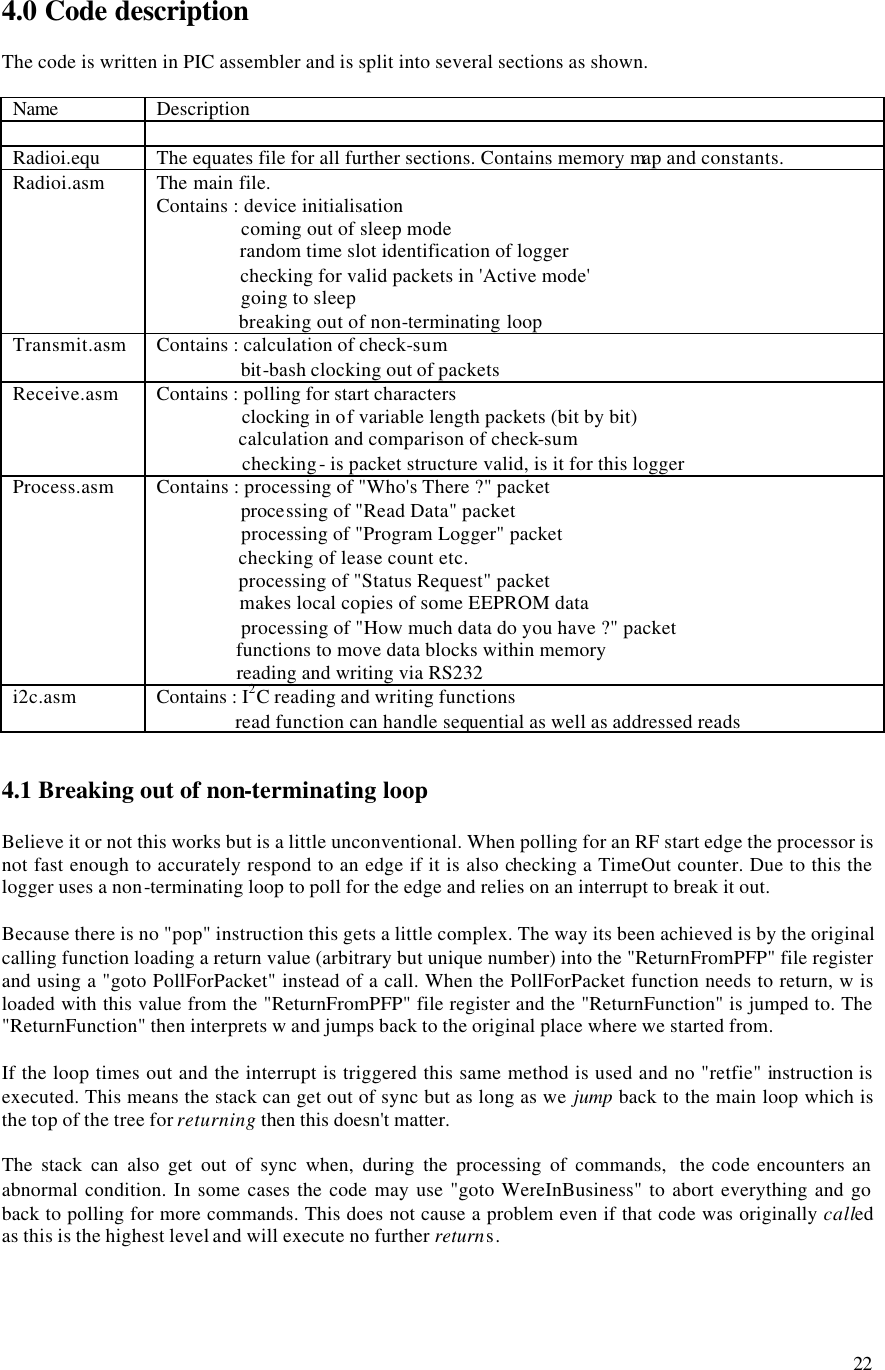
![13 D[23:end] : padding All multi byte quantities have MSB at the highest address.](https://usermanual.wiki/Escort-Data-Logging-Systems/MINI.USERS-MANUAL/User-Guide-639765-Page-14.png)
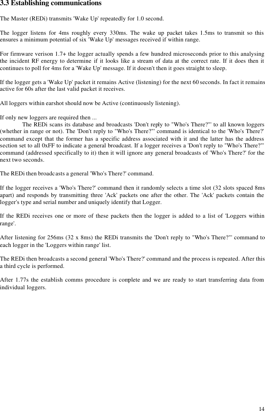
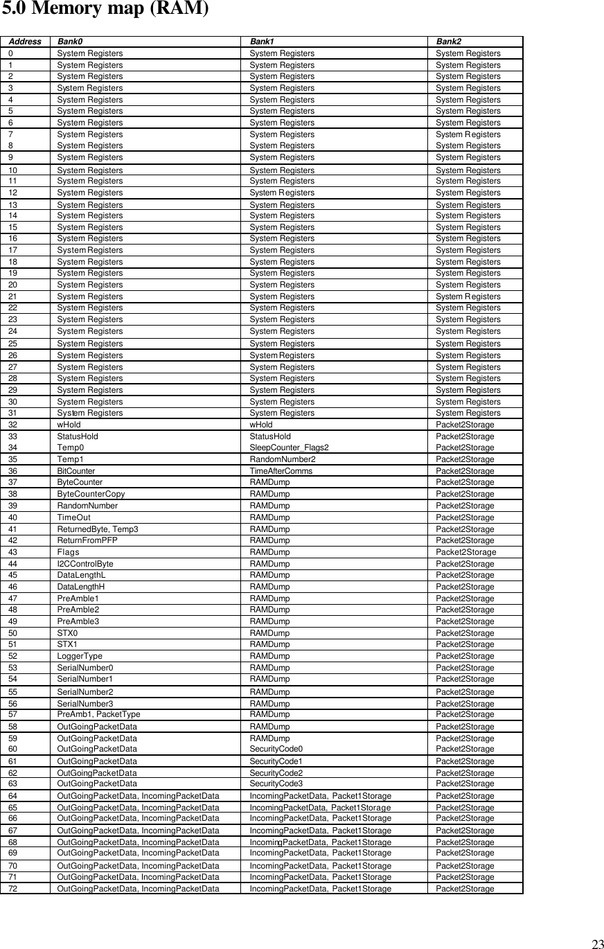
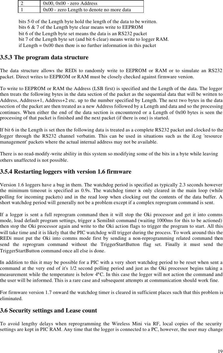
![17 3.5 Writing to a logger 3.5.1 The Write process The REDi sends a 'Program Logger' command which contains a security code. If the logger is leased and the lease has expired then the logger replies with a 'LeaseExpired' packet and returns to listening for command packets. In fact the lease count must be checked at the time of reprogramming because the logger may be in the Ready or Logging state and this may affect whether it can be reprogrammed. See section 3.6 for more detail. If the Master (REDi) gets a 'LeaseExpired' reply then it should send an 'UpdateLeaseCount' packet then try the 'Program Logger' command again. If the logger is password protected for programming and the security code does not match the loggers code then it replies with a 'BadPassword' packet and returns to listening for command packets. If the security code etc. is valid then the logger replies with an 'Ack'. The logger then decodes the command packet to determine if there are packets to follow. There could be up to 3. If no further packets are expected then the logger gets on with processing the flags. If further packets are expected then the REDi sends each one in turn. The logger replies to each packet with an 'Ack' if received correctly. Once all packets are received they are processed in reverse order. Packet #3 is processed first, then #2, then #1 then the flags in the original command packet are processed. For firmware version 1.7+ a flag called 'LastProgramOK' is cleared as soon as a 'Program Logger' command is received. If the program gets correctly implemented (ie. the Oki processor acknowledges all packets sent to it and the PIC code completes the reprogramming loop) then this flag is set. It is available in the 'Status' packet and should be checked by the REDi Master after reprogramming a logger. For firmware version 1.6 the REDi Master must read back the lower 64 bytes of EEPROM and check the signature of the program to verify correct implementation. 3.5.2 Packets associated with the write process The Program Logger packet Field name # bytes Field content Preamble 3 0xAA,0xAA,0xAA Start character 2 0x72, 0x65 Recipient 5 TSSSS (Logger Type, Serial Number) Packet type 1 0x16 Data 6 [ Note 1 ] Check Sum 2 Fletcher](https://usermanual.wiki/Escort-Data-Logging-Systems/MINI.USERS-MANUAL/User-Guide-639765-Page-18.png)
![18 Note 1 : Data structure byte 0 number of packets to follow (only lowest 2 bits recognised so max. 3 packets) byte 1 flags [ Note 2 ] byte 2 SecurityCode#0 byte 3 SecurityCode#1 byte 4 SecurityCode#2 (not used in Wireless Mini) byte 5 SecurityCode#3 (not used in Wireless Mini) Note 2 : Flags bit 0 Load default values into logger registers [ Note 3 ] bit 1 Start the program waiting for button bit 2 Simulate the press of a button to begin the program bit 3 Spare bit 4 0 (note these higher bits must be zero and cannot be used) bit 5 0 bit 6 0 bit 7 0 Note 3 : The default values to load NumberOfLogsTaken = 0x00 TimeOverTemperature = 0xAA,0xA0,0x00 CurrentLogAddress = 0x00B4 TimeUnderTemperature = 0xAA,0xA0,0x00 UpperAlarmCounts = 0x00 HighestLog = 0x00 LowerAlarmCounts = 0x00 LowestLog = 0xFF AlarmControl = 0xF- SumOfAllLogs = 0x00,0x00,0x00 Followed by 0 to 3 Long Data Packet(s) : Field name # bytes Field content Preamble 3 0xAA,0xAA,0xAA Start character 2 0x72, 0x65 Logger 5 TSSSS (Logger Type, Serial Number) Packet type 1 0xF2 Data 48 Always 48 bytes in length [ Note 4 ] Reference 4 Packet number 0,1 or 2 (only one byte used) Check Sum 2 Fletcher Note 4 : Data structure # bytes Description 2 Address (LSB first) 1 Length N variable length data 2 Address 1 Length N variable length data 2+1+N further Address,Length,Data sections](https://usermanual.wiki/Escort-Data-Logging-Systems/MINI.USERS-MANUAL/User-Guide-639765-Page-19.png)
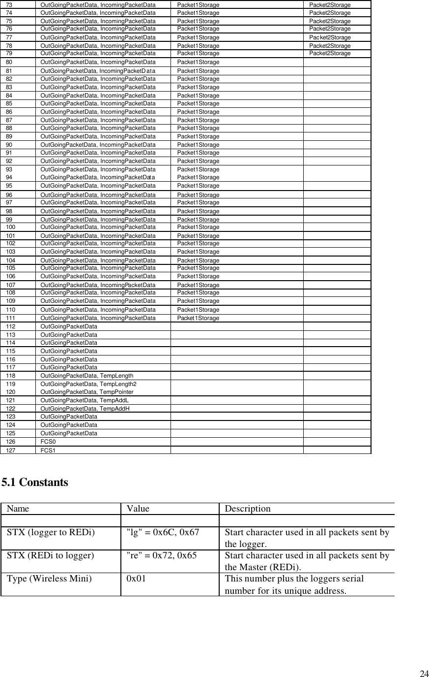
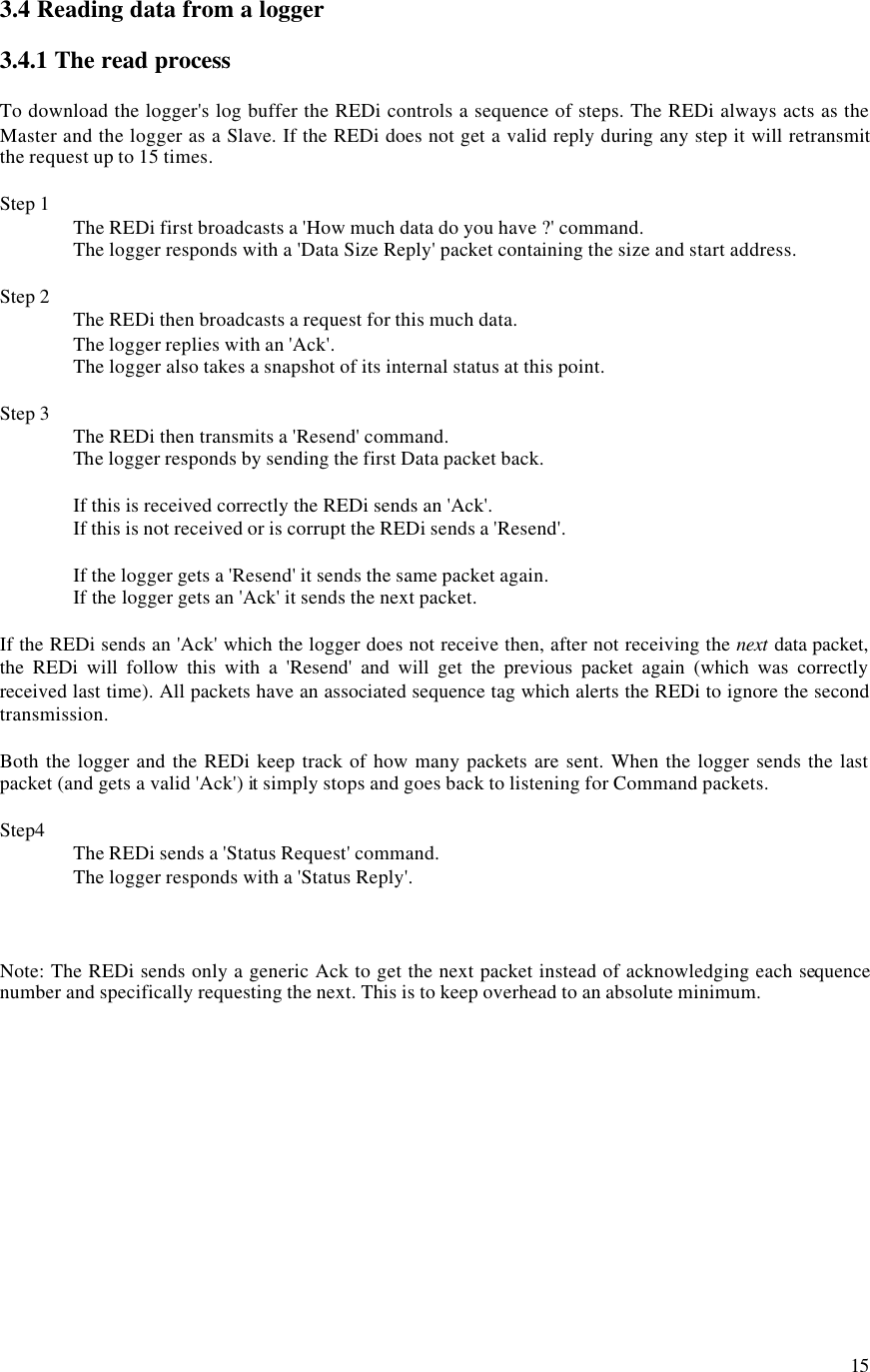
![20 these settings in EEPROM. To get around this the RF Implant monitors the power supply to the RS232 circuitry and when it sees activity start then cease it starts a counter. Two seconds after comms activity has ceased, the PIC copies the two bytes of SecurityCode (four BCD digits) to local RAM. It reads the UserFlags and makes a note of whether the program is protected by password or not. It also reads the LeaseControl byte and if the logger is leased then regardless of the lease count it sets an internal flag saying that the lease has expired. When it receives a 'ProgramLogger' packet it will check its internal flag to see if the lease has expired. If it is a leased logger then it will believe that it has and will reply with a 'LeaseExpired' packet. This may or may not be true. The Master should then issue a 'CheckLeaseCount' packet and, after a valid 'Ack', try to program a second time. If the logger reports 'LeaseExpired' a second time this must be believed. This all seems horribly complicated but the problem with lease count is that the Oki firmware is oblivious to it. This means that the device which reprograms it (PC, ChartReader or RF Implant) must decide, based on the logging state and leasecount, whether to allow another trip or not. The rule is that if a program has been loaded but not started then the lease count is not decreased and another program can be set. If the program has been started then the lease count should be decreased, and only if it is now greater than zero should a new program be allowed. As the logger can be started at any stage by the user pressing the button on the logger, the logging state must be checked at the time of reprogramming. Once passed all this the Implant will check the ProgramProtected flag and if so it will check for a password match. If the password doesn't match it will reply with a 'BadPassword' packet otherwise it will get on with clocking in any subsequent packets and reprogramming the logger. If the logger was in a state other than Ready then the TripCount is increased when a program is set and if the logger is leased then the LeaseControl cycle count is decreased. Note: As of version 1.6 of the firmware it is possible to change security settings using a PC, then before two seconds have elapsed, connect to the logger using RF and attempt to reprogram. The new settings will not have been copied to local RAM. After RF comms cease (after 60s of inactivity) and the Implant returns the waking/sleeping mode where the balance of the two seconds will elapse and the settings will then get copied. This is unlikely to cause any serious problem but could be improved in future firmware versions. 3.7 Status request The Status Reply packet Field name # bytes Field content Preamble 3 0xAA,0xAA,0xAA Start character 2 0x6C, 0x67 Logger 5 TSSSS (Logger Type, Serial Number) Packet type 1 0x14 Data 32 D0 : low byte of Implant f/w version D1 : high byte of Implant f/w version D2 : low byte of Oki f/w version D3 : high byte of Oki f/w version D4 : case type D[5:22] : Status packet from host [ Note 1 ] D[23] : Wireless Mini Status flags [ Note 2 ] D[24:31] : padding Check Sum 2 Fletcher](https://usermanual.wiki/Escort-Data-Logging-Systems/MINI.USERS-MANUAL/User-Guide-639765-Page-21.png)