Escort Data Logging Systems MINI PORTABLE DATA LOGGING DEVICE User Manual LCD Mini technical manual10e
Escort Data Logging Systems Ltd PORTABLE DATA LOGGING DEVICE LCD Mini technical manual10e
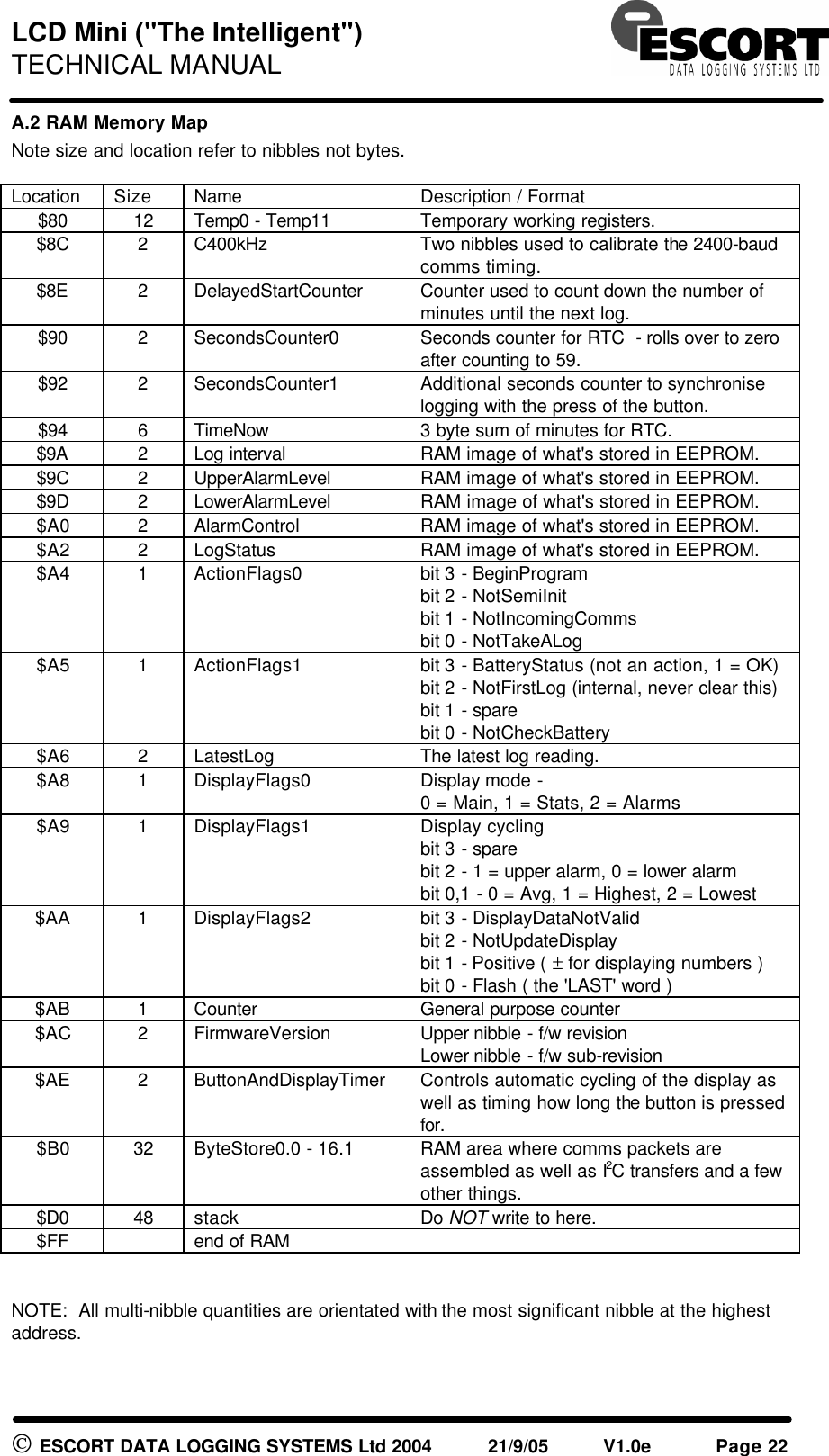
Contents
- 1. USERS MANUAL
- 2. TECHNICAL MANUAL
- 3. QUICK REFERENCE GUIDE
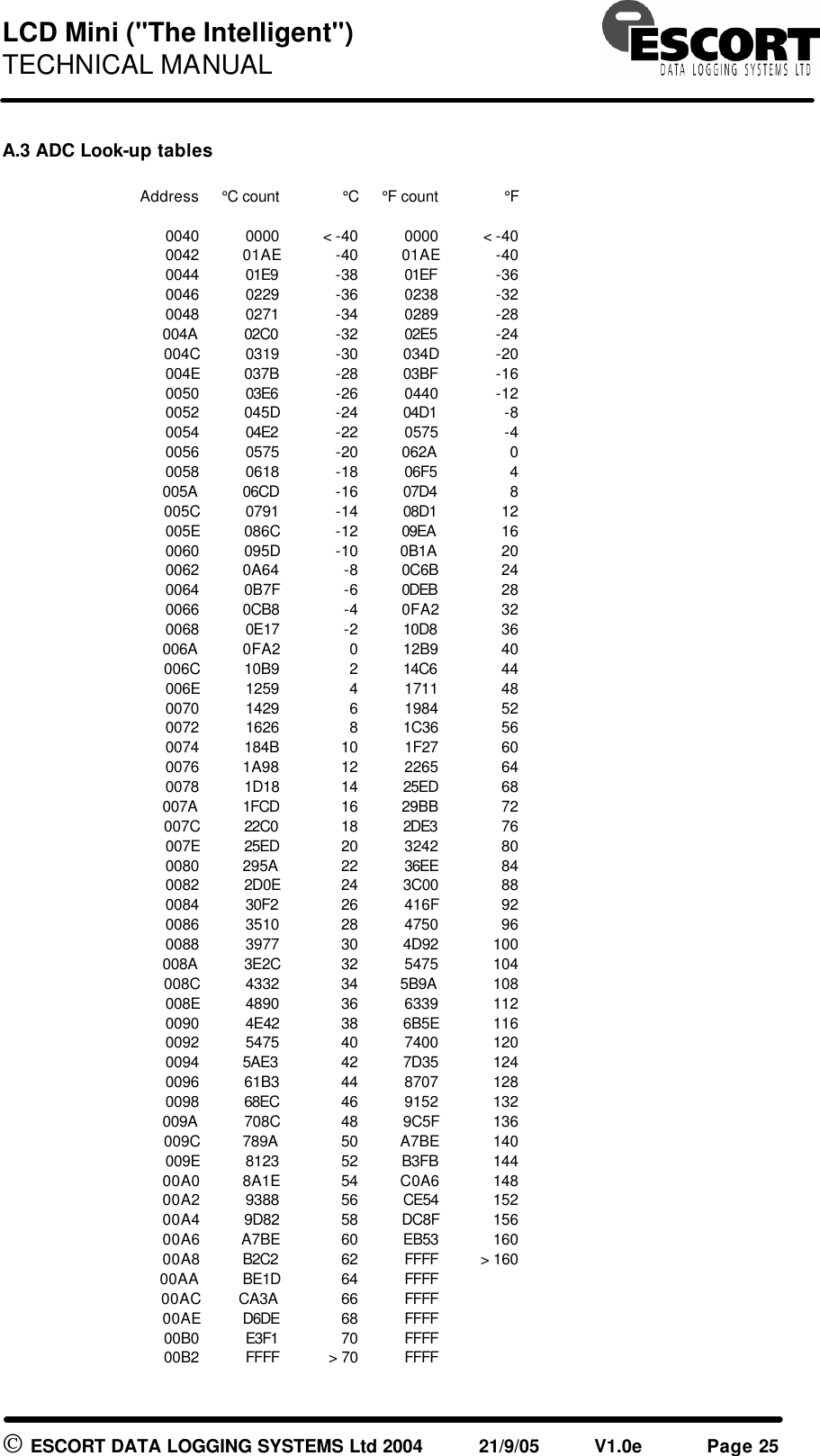
TECHNICAL MANUAL
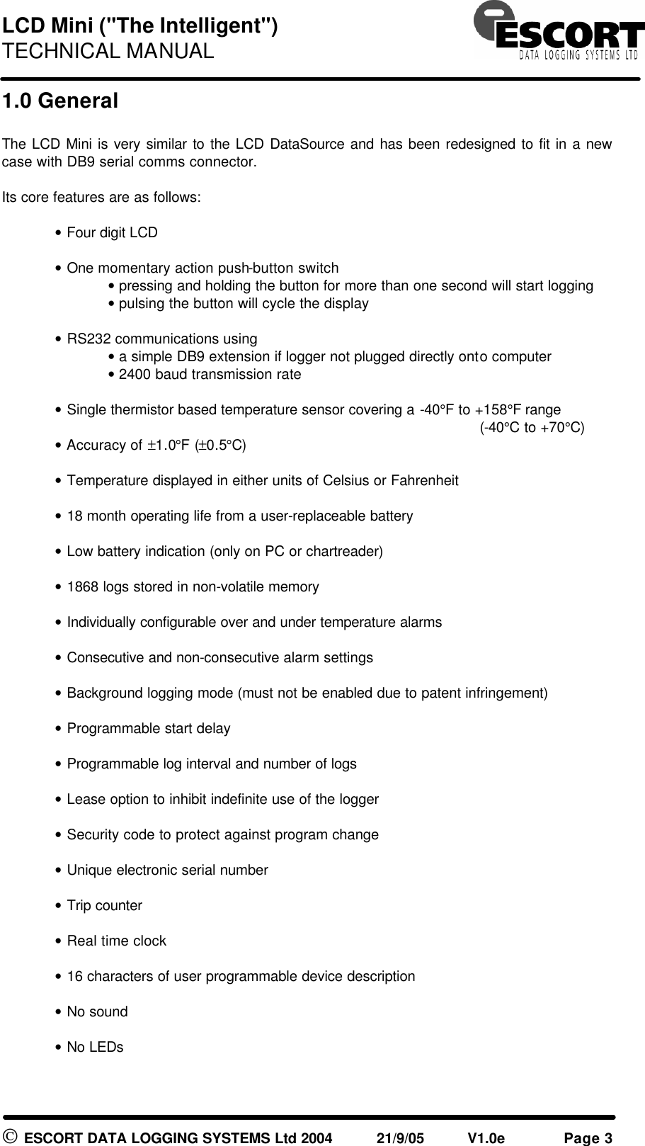
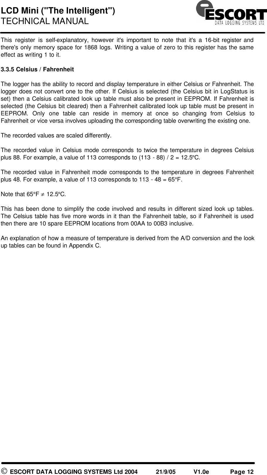
![LCD Mini ("The Intelligent") TECHNICAL MANUAL ESCORT DATA LOGGING SYSTEMS Ltd 2004 21/9/05 V1.0e Page 4 Product code: [FF] - [XX] - [R(R)] - [M] - [Options] [FF] Family MI- Intelligent Mini (LCD Mini or Wireless Mini) [XX] Sensor combination IN Internal sensor OE No internal but external sensor on cable [R(R)] Temperature Range D D-Range [M] Memory size 2 1868 readings (2KB) [Options] L LCD LR8 LCD & 868 MHz LR9 LCD & 916 MHz Example: Wireless Mini 916 MHz, external sensor: MI-OE-D-2-LR9](https://usermanual.wiki/Escort-Data-Logging-Systems/MINI.TECHNICAL-MANUAL/User-Guide-639766-Page-4.png)