Escort Data Logging Systems MINI PORTABLE DATA LOGGING DEVICE User Manual LCD Mini technical manual10e
Escort Data Logging Systems Ltd PORTABLE DATA LOGGING DEVICE LCD Mini technical manual10e
Contents
- 1. USERS MANUAL
- 2. TECHNICAL MANUAL
- 3. QUICK REFERENCE GUIDE
TECHNICAL MANUAL

LCD Mini ("The Intelligent")
TECHNICAL MANUAL
ESCORT DATA LOGGING SYSTEMS Ltd 2004 21/9/05 V1.0e Page 1
LCD Mini:
The Intelligent
TECHNICAL MANUAL
V1.0e
FOR LCD Mini/DataSource/Wireless Mini mask revision 1.0
Revision history
1.0 JAL 12/5/04 - Renamed & edited LCD DataSource manual 1.8
1.0b JAL 7/9/04 - Bit 4 of User flags ($31 in EEPROM) set = Ext sensor
1.0c AS 04-05-2005 – Product Code definition
1.0d WCH 1/8/5 - RF f/w ver. stored in EEPROM
1.0e WCH 21/9/5 - List of features updated

LCD Mini ("The Intelligent")
TECHNICAL MANUAL
ESCORT DATA LOGGING SYSTEMS Ltd 2004 21/9/05 V1.0e Page 2
CONTENTS
1.0 General....................................................................................................................... 3
1.1 Hardware ................................................................................................................. 5
1.2 Low battery indication ............................................................................................... 5
1.3 Reset ...................................................................................................................... 5
1.4 Scalability................................................................................................................ 6
1.5 Time management .................................................................................................... 6
2.0 Communications.......................................................................................................... 7
2.1 Packet structure....................................................................................................... 7
2.2 Accessing EEPROM ................................................................................................ 8
2.3 Accessing RAM ....................................................................................................... 9
2.4 Reading the firmware version...................................................................................... 9
2.5 Reading the battery status......................................................................................... 9
3.0 Program operation.......................................................................................................10
3.1 General...................................................................................................................10
3.2 Background logging .................................................................................................10
3.3 Setting a program....................................................................................................10
4.0 Alarms and Statistics..................................................................................................13
4.1 AlarmControl register ...............................................................................................13
4.2 AlarmDelays register................................................................................................13
4.3 Upper and Lower alarm levels....................................................................................13
4.4 TimeOverTemperature / TimeUnderTemperature..........................................................14
4.5 Statistics................................................................................................................14
5.0 User options...............................................................................................................15
5.1 Lease option ...........................................................................................................15
5.2 Security code..........................................................................................................15
5.3 Trip Count ...............................................................................................................15
6.0 LCD operation.............................................................................................................16
6.1 Basic functionality ...................................................................................................16
6.2 Main state...............................................................................................................16
6.3 Statistics State.......................................................................................................18
6.4 Alarms State...........................................................................................................18
Appendix A......................................................................................................................19
A.1 EEPROM Memory Map. ..........................................................................................19
A.2 RAM Memory Map..................................................................................................22
A.3 ADC Look-up tables ................................................................................................25
Appendix C - Firmware revision history ...............................................................................27

LCD Mini ("The Intelligent")
TECHNICAL MANUAL
ESCORT DATA LOGGING SYSTEMS Ltd 2004 21/9/05 V1.0e Page 3
1.0 General
The LCD Mini is very similar to the LCD DataSource and has been redesigned to fit in a new
case with DB9 serial comms connector.
Its core features are as follows:
• Four digit LCD
• One momentary action push-button switch
• pressing and holding the button for more than one second will start logging
• pulsing the button will cycle the display
• RS232 communications using
• a simple DB9 extension if logger not plugged directly onto computer
• 2400 baud transmission rate
• Single thermistor based temperature sensor covering a -40°F to +158°F range
(-40°C to +70°C)
• Accuracy of ±1.0°F (±0.5°C)
• Temperature displayed in either units of Celsius or Fahrenheit
• 18 month operating life from a user-replaceable battery
• Low battery indication (only on PC or chartreader)
• 1868 logs stored in non-volatile memory
• Individually configurable over and under temperature alarms
• Consecutive and non-consecutive alarm settings
• Background logging mode (must not be enabled due to patent infringement)
• Programmable start delay
• Programmable log interval and number of logs
• Lease option to inhibit indefinite use of the logger
• Security code to protect against program change
• Unique electronic serial number
• Trip counter
• Real time clock
• 16 characters of user programmable device description
• No sound
• No LEDs

LCD Mini ("The Intelligent")
TECHNICAL MANUAL
ESCORT DATA LOGGING SYSTEMS Ltd 2004 21/9/05 V1.0e Page 4
Product code:
[FF] - [XX] - [R(R)] - [M] - [Options]
[FF] Family
MI- Intelligent Mini (LCD Mini or Wireless Mini)
[XX] Sensor combination
IN Internal sensor
OE No internal but external sensor on cable
[R(R)] Temperature Range
D D-Range
[M] Memory size
2 1868 readings (2KB)
[Options]
L LCD
LR8 LCD & 868 MHz
LR9 LCD & 916 MHz
Example:
Wireless Mini 916 MHz, external sensor: MI-OE-D-2-LR9

LCD Mini ("The Intelligent")
TECHNICAL MANUAL
ESCORT DATA LOGGING SYSTEMS Ltd 2004 21/9/05 V1.0e Page 5
1.1 Hardware
The LCD Mini is based around the 4-bit OKI MSM64162A microcontroller. This controller is
specifically designed for battery powered electronic temperature measurement so has a
significant amount of the required hardware built in. As well as the CPU core, it incorporates the
LCD drivers, ADC and battery check circuit.
External to the controller are a 2k I
2C EEPROM (24LC16), the LCD, a 3V 550mAH disc cell
(CR2450), and the thermistor sensor (10K3A1B).
The 64162 uses the thermistor as the resistive component in an RC oscillator and uses the
measured frequency to determine the resistance. A full description of how this method is
implemented can be found in Appendix B.
The EEPROM is guaranteed for one million write-cycles. As many variables are written to
EEPROM every time a log is taken and it is possible to set the logger to log once per minute
almost continuously, a worst case scenario is that the EEPROM could fail after 1.9 years.
1.2 Low battery indication
The logger uses a circuit built into the microcontroller to measure its battery level. This is only
an approximate test and is really a 'marketing feature' rather than accurate and reliable
information. Among other things, it is temperature dependent and the trip level has been set for
operation at 25°C.
This internal circuit is used due to low cost, and will require the selection of two external
resistors based on a measurement of the microcontroller's characteristic. The circuit compares
the level of a voltage divider (the two external resistors) with the level of a diode drop below the
supply level. As the supply level decreases the constant diode drop decreases faster than the
voltage divided level, and the cross over point determines the trigger level for the circuit. The
value of the diode drop is not precise and will require measurement on a microcontroller batch
basis. Using software to compensate for variation in this circuit is possible but not practical.
The battery level is not displayed on the LCD and a reading can only be instigated by a PC (or a
chartreader).
1.3 Reset
The design ideology has been to keep running if at all possible. All operation variables are
backed up to EEPROM and reloaded when and if the microcontroller is reset.
The real time clock is not backed up so if this gets corrupted in RAM then the problem can only
be corrected by PC software.
The microcontroller has a watch dog timer which attempts to ensure that if the main code
crashes then the watch dog code will be executed. The reset pin of the micro is tied to an
output port and the watch-dog interrupt has been set up such that a software crash will drive this
pin low resulting in a full hardware reset.
The PC or chartreader can trigger a partial reset by clearing an active low flag called
NotSemiInit. This has the same effect as a full reset except it does not set up the port
directions and it does not specifically reset any special function registers (including stack
pointer).

LCD Mini ("The Intelligent")
TECHNICAL MANUAL
ESCORT DATA LOGGING SYSTEMS Ltd 2004 21/9/05 V1.0e Page 6
If the device has operational comms then the PC or chartreader can also force a hard reset. This
is a dubious feature - the tidy way of doing this has been removed to free up some code space.
(To force a reset the PC or chartreader must write the address of the watchdog code over the
return vector in the stack area, then allow the comms function to time out and return.)
1.4 Scalability
Little attention has been paid to future proofing the design. Most notably a change in memory
size will not be possible without creating another mask for the microcontroller.
1.5 Time management
The logger manages time in the form of two seconds registers and a 3-byte minutes register. (3
byte minutes = 16,777,215 minutes = 32 years)
The time datum is arbitrary (and not stored on the logger) but is intended to be midnight
December 31 1999.
The 6-nibble TimeNow register holds the number of minutes elapsed since the time datum in
binary form. The SecondsCounter0 register holds the number of seconds.
The SecondsCounter1 register holds a measure of seconds elapsed since the program was
started. When the button is pressed and held for exactly one second this counter is loaded with
the value 58. When this counter rolls over from 59 to 00 the first log is taken (or the delayed
start initiated).

LCD Mini ("The Intelligent")
TECHNICAL MANUAL
ESCORT DATA LOGGING SYSTEMS Ltd 2004 21/9/05 V1.0e Page 7
2.0 Communications
Mode : RS232
2400 baud,
1 start bit, 1 stop bit,
8 bits data, No parity
TX (Host->Logger) minimum inter-character delay : 500µs
RX (Logger->Host) maximum inter-character delay : 1ms
Recommended RX timeout (waiting for reply) : 10ms
Recommend Retry Count : 5
The comms are performed by bit-bashing two GPIO port pins.
Because the OKI-64162 is 4-bit, its code efficiency is quite low and therefore can't achieve
acceptable comms rates while running from a 32kHz clock. However, it has a high-speed mode
where it operates from a 400kHz RC oscillator and the comms takes advantage of this.
To initiate communications the communicating device must first send a 'kick start' character.
Activity on the Rx line triggers an interrupt in the microcontroller which in turn tells it to wake up,
switch to high speed mode, calibrate the RC oscillator against the more accurate 32k768Hz
crystal, then start polling the Rx line for a start bit.
This takes a maximum of 400ms then the micro will remain polling the comms for 875ms. If, at
any stage, there is no comms activity for 875ms the comms function will time out and the
processor will slow down and go to sleep again. Once a packet has been received (either
correctly of incorrectly) and a reply has been sent (if the packet was valid), the 875ms time out
period is restarted.
It is imperative to keep the real time clock running continuously which means that a 1Hz
interrupt must be momentarily enabled after each packet is received. This can cause the
detection of the next start bit to be unacceptably delayed and the subsequent packet misread
and rejected. From the PC or chartreader's point of view this means occasionally packets won't
get through, and, in the absence of a reply from the logger, must be resent. In addition to this if
comms are initiated part way through an A/D conversion then the loggers response will be
delayed by up to a second and it will miss any packets sent during this time. If however, the
scenario is reversed and the logger is in comms mode while the "time to take a log" flag
becomes set, then the actual taking of the log is deferred until the comms function times out.
Care should therefore be taken, as this means it is possible for a log to be skipped if comms
takes longer than the log interval.
2.1 Packet structure
There are only two possible commands that can be written to the logger. These are read
memory and write memory. The PC or chartreader software has free access to every EEPROM
and RAM location (including stack area etc.). To trigger an action such as force the device to
perform a conversion the software must 'fiddle' the logger's internal registers. The internal
memory structure has been designed with this in mind.
LCD Mini ("The Intelligent")
TECHNICAL MANUAL
ESCORT DATA LOGGING SYSTEMS Ltd 2004 21/9/05 V1.0e Page 8
2.1.1 Write packet
byte 0 Start character (A3)
byte 1 bits 4 to 7 Command nibble (0 = write)
byte 1 bits 0 to 3 The total number of bytes in the packet
byte 2 Low byte of destination address
byte 3 bit 7 Memory bank (1 = RAM, 0 = EEPROM)
byte 3 bits 0 to 6 High 'byte' of destination address
byte 4 Number of bytes to write
bytes 5 to end-1 Data bytes
final byte Check sum
2.1.2 Write reply packet
byte 0 Start character (A3)
byte 1 bits 4 to 7 Write reply nibble (1)
byte 1 bits 0 to 3 The total number of bytes in the packet (3)
byte 2 Check sum (B6)
2.1.3 Read packet
byte 0 Start character (A3)
byte 1 bits 4 to 7 Command nibble (8 = read)
byte 1 bits 0 to 3 The total number of bytes in the packet (6)
byte 2 Low byte of source address
byte 3 bit 7 Memory bank (1 = RAM, 0 = EEPROM)
byte 3 bits 0 to 6 High 'byte' of source address
byte 4 Number of bytes required
byte 5 Check sum
2.1.4 Read reply packet
byte 0 Start character (A3)
byte 1 bits 4 to 7 Read reply nibble (9)
byte 1 bits 0 to 3 The total number of bytes in the packet
bytes 2 to end-1 Data bytes
final byte Check sum
The logger makes no attempt to verify any data that is written to it however for a packet to be
accepted it must have a correct start character, length, and check sum. The check sum is
simply the 8-bit summation of all the bytes in the packet.
The maximum packet length is 16 bytes. Attempting to write packets longer than this will result
in them being ignored and asking for more data than will fit in a read reply packet will result in a
corrupt packet being sent.
2.2 Accessing EEPROM

LCD Mini ("The Intelligent")
TECHNICAL MANUAL
ESCORT DATA LOGGING SYSTEMS Ltd 2004 21/9/05 V1.0e Page 9
It is not practically possible to fit 16 data bytes into a comms packet, so due to the banked
nature of the EEPROM, logs will need to be up loaded in groups of 8. With the packet overhead,
this will take roughly 30 seconds to up load the entire 2k memory.
The 'banked nature' of the EEPROM refers to fact that data in EEPROM is read and written
using a packet structure. The packet has a start address followed by up to 16 bytes of data
however any single read or write cannot cross a 16 byte page boundary. Attempting to will result
in wrap around ie. If the start address of a read packet is $2D and the data length is 5 then the
data will be read from addresses $2D, $2E, $2F, $20, $21.
2.3 Accessing RAM
RAM is organised as nibbles and the comms structure is based around bytes so some
compromises are required. The RAM address to read or write should be the nibble address as
shown in Appendix A.2 but should always be even. Note that the high 'byte' of the address (bits
0 - 6 of byte 3 in the packet) is simply ignored. The data length field in the comms packet is
always in bytes so nibbles can only be read and written to RAM in pairs.
Although the 64162 memory architecture is banked in a similar fashion to the EEPROM this
has been made transparent to comms so restrictions on page boundaries do not apply.
WARNING! Because of the flexible nature of the comms, it is possible to crash the logger by
writing to the stack area. It is desirable to avoid doing this.
2.4 Reading the firmware version
Because no status request command exists the firmware version is stored in RAM and can be
directly read from there. The RTC interrupt updates this location once per second with the hard
coded version number so it is effectively a read only address.
The firmware version is stored as a byte. The lower nibble represents the sub-revision, the upper
nibble represents the revision and if there is any response at all then this represents the LCD
Mini.
2.5 Reading the battery status
The logger will not check the battery of its own accord. To find out the battery status, the
software must ensure that the BatteryStatus flag in ActionFlags1 in RAM is cleared. The
software must then trigger the logger to take a reading by resetting the active low
'NotCheckBattery' flag in this nibble.
For the battery test to occur the logger must exit comms mode by timing out (after 875ms). The
battery will be subsequently checked (taking just less than 30ms) and the BatteryStatus flag
set if the battery voltage is above the specified threshold. If the battery is below the threshold
this flag is not explicitly cleared but remains unchanged (which is why the PC or chartreader
must ensure it's cleared initially). The software must then read the ActionFlags1 nibble from
RAM and interrogate this bit.

LCD Mini ("The Intelligent")
TECHNICAL MANUAL
ESCORT DATA LOGGING SYSTEMS Ltd 2004 21/9/05 V1.0e Page 10
3.0 Program operation
3.1 General
The logger is controlled by a program loaded into it using a PC (or rearmed by a chartreader).
The user can either start the logger program using the PC or chartreader or set it to be started
using the push button.
When the program begins the logger waits for a variable length start delay to elapse before
taking the first log. This delay can be set to any integer number of minutes from 0 to 255.
The logger also records the time of day to an accuracy of 1 minute when the program is started.
The TimeNow field in RAM is copied to the StartLogTime field in EEPROM immediately prior to
the first log being taken. If a delayed start is programmed, the time is copied after the delay has
elapsed.
Once the start delay has elapsed, the logger will record the temperature periodically at the
programmed log interval. The log interval can be set to any integer number of minutes from 1 to
256.
The logger will continue this cycle until it has taken the specified number of logs then it will stop
recording. The specified number of logs can be set to any number, which must be from 1 to
1868 to avoid overwriting earlier recorded data.
The logger program cannot be stopped prematurely without using a PC or a chartreader.
3.2 Background logging
The logger can optionally have a background-logging mode enabled. In this case, the logger will
continuously record the temperature at the specified log interval (the same interval used for the
program) prior to the program being started.
When the program is started the logger will suspend background logging and begin the program
as described above. If a delayed start has been programmed, no logs will be recorded during the
delay period.
At the completion of the program, background logging will remain suspended and no further
readings will be taken.
If the program is not started, background logging will continue indefinitely.
The logger can record a maximum of 1868 logs so if more than this number of logs are taken in
background logging mode, the oldest logs will be overwritten with the most recent logs.
3.3 Setting a program
All set up for the program can be done by writing only to EEPROM. However, some EEPROM
stored values are echoed in RAM (to reduce processing overhead each time they're needed), so
it is necessary to trigger the micro to copy them over. This is done by clearing the active low
NotSemiInit flag in the ActionFlags1 in RAM. This in turn will copy all relevant data to RAM and

LCD Mini ("The Intelligent")
TECHNICAL MANUAL
ESCORT DATA LOGGING SYSTEMS Ltd 2004 21/9/05 V1.0e Page 11
will reset the display mode to Main. It will also measure the battery level but this can be
ignored.
The program sequence is controlled by the LogStatus register.
3.3.1 LogStatus register
Bit Name Description
7 Celsius Set to display temperatures in Celsius. Clear for Fahrenheit.
6 Wrapped This flag gets set when the NextLogAddress wraps from 07FF to
00B4. The f/w never clears it.
5 LogStartType This flag is ignored by the firmware but is reserved for external
software to set to indicate a switch start, or clear otherwise.
4 ReadDelay Internal flag - set in the button interrupt to tell the foreground to
copy the start delay from EEPROM to RAM.
3 NotStopped Active low - Indicates that the program has finished and no
further logs should be taken. This bit over-rides bits 0 -2.
2 NotCurrentlyLogging Active low - indicates that the logging cycle of the program is
active, i.e. the start delay has finished.
1 ProgramRunning Active high - Indicates that program has been started, i.e. the
program is in some state other than ready.
0 NotBackgroundLogging Active low - Sets background logging mode. This bit over-rides
bits 1 and 2.
To correctly set a program the above register should have the relevant bits set (e.g. $2D or $AD
for a normal program with button start and background logging disabled) as well as the relevant
values written to the NumberOfLogsToTake, StartDelay, and LogInterval registers.
An "Immediate" start is effected by setting the BeginProgram bit instead of clearing the
NotSemiInit flag. In this case, the startup delay is re-read from EEPROM regardless of the
setting of the ReadDelay flag above. If this value is not zero, the startup delay will commence.
If background logging is to be used then the value in CurrentLogAddress should be set to the
start of the log buffer ($00B4) first, so that it is known where to extract the data from if needed.
In addition, the Wrapped flag should be cleared so that wrapping can be detected if it occurs.
3.3.2 StartDelay register
The start delay register defines a period of N minutes inactivity between the start of the program
and the first log being taken. During this time, no readings are taken even if background logging
is enabled. There are no flags to turn this feature off - to start immediately simply write a value of
zero to this register.
3.3.3 LogInterval register
The log interval register defines the period between consecutive logs. This timing is used both
for normal program operation as well as for background logging. The period is in minutes. A
value of zero represents 256 minutes.
3.3.4 NumberOfLogsToTake register

LCD Mini ("The Intelligent")
TECHNICAL MANUAL
ESCORT DATA LOGGING SYSTEMS Ltd 2004 21/9/05 V1.0e Page 12
This register is self-explanatory, however it's important to note that it's a 16-bit register and
there's only memory space for 1868 logs. Writing a value of zero to this register has the same
effect as writing 1 to it.
3.3.5 Celsius / Fahrenheit
The logger has the ability to record and display temperature in either Celsius or Fahrenheit. The
logger does not convert one to the other. If Celsius is selected (the Celsius bit in LogStatus is
set) then a Celsius calibrated look up table must also be present in EEPROM. If Fahrenheit is
selected (the Celsius bit cleared) then a Fahrenheit calibrated look up table must be present in
EEPROM. Only one table can reside in memory at once so changing from Celsius to
Fahrenheit or vice versa involves uploading the corresponding table overwriting the existing one.
The recorded values are scaled differently.
The recorded value in Celsius mode corresponds to twice the temperature in degrees Celsius
plus 88. For example, a value of 113 corresponds to (113 - 88) / 2 = 12.5°C.
The recorded value in Fahrenheit mode corresponds to the temperature in degrees Fahrenheit
plus 48. For example, a value of 113 corresponds to 113 - 48 = 65°F.
Note that 65°F ≠ 12.5°C.
This has been done to simplify the code involved and results in different sized look up tables.
The Celsius table has five more words in it than the Fahrenheit table, so if Fahrenheit is used
then there are 10 spare EEPROM locations from 00AA to 00B3 inclusive.
An explanation of how a measure of temperature is derived from the A/D conversion and the look
up tables can be found in Appendix C.

LCD Mini ("The Intelligent")
TECHNICAL MANUAL
ESCORT DATA LOGGING SYSTEMS Ltd 2004 21/9/05 V1.0e Page 13
4.0 Alarms and Statistics
Alarms are visually indicated by the HIGH ALARM 1 and/or LOW ALARM 1 sections of the
LCD.
The alarms are controlled by the flags in the lower nibble of the AlarmControl register as well as
the AlarmDelays register. The alarm status can be read by the PC or chartreader by examining
the upper nibble of the AlarmControl register and Upper and Lower alarms counts registers.
The firmware does not initialise any of these flags or registers when the program is started so
initialisation must be performed by the PC or chartreader.
4.1 AlarmControl register
Bit Name Description
7 PreviousLogUnder Internal flag - used to determine if consecutive errors have
occurred
6 PreviousLogOver Internal flag - used to determine if consecutive errors have
occurred
5 NotLowAlarmOn Active low - Indicates the low alarm has been triggered
4 NotHighAlarmOn Active low - Indicates the high alarm has been triggered
3 ConsecutiveDisable Active low - Clearing this flag enables consecutive alarm
triggering
2 Non-consecutiveDisable Active low - Clearing this flag enables non-consecutive
alarm triggering
1 LowerAlarmEnable Active high - Enables testing for under range conditions
0 UpperAlarmEnable Active high - Enables testing for over range conditions
4.2 AlarmDelays register
Bit Name Description
4-7 ConsecutiveDelay Indicates one less than the number of consecutive out of
range conditions that must have occurred before an alarm
is tripped - must be non-zero.
0-3 Non-consecutiveDelay Indicates the total number of out of range conditions that
must have occurred before an alarm is tripped - must be
non zero.
The UpperAlarmCounts and LowerAlarmCounts registers are the same format as the
AlarmDelays register and record the number of consecutive and non-consecutive out of range
conditions that have occurred for the respective alarm. The alarm is turned on when a nibble in
one of these registers becomes equal to the corresponding nibble in the AlarmDelays register.
4.3 Upper and Lower alarm levels
The UpperAlarmLevel and LowerAlarmLevel registers hold the values that define the valid
temperature range. These levels are specified in either degrees Fahrenheit + 48, i.e. the value
50 corresponds to 2°F OR in twice the degrees Celsius + 88, i.e. the value 50 corresponds to
-19°C. The levels indicate the maximum and minimum safe levels - the measured value must fall
outside this range to trigger the alarm.

LCD Mini ("The Intelligent")
TECHNICAL MANUAL
ESCORT DATA LOGGING SYSTEMS Ltd 2004 21/9/05 V1.0e Page 14
4.4 TimeOverTemperature / TimeUnderTemperature
The time spent over and under temperature is counted and displayed on the LCD. The display
resolution only goes down to tens of minutes but the units of minutes are recorded to maintain
accuracy. The format is shown in the EEPROM memory map. These registers are not initialised
by the firmware so must be by the PC or chartreader.
These values do not include logs taken during background logging, but do include the time
spent outside the valid range prior to the relevant alarm being tripped. These registers are only
incremented if the associated alarms are enabled.
If the very first log is out of range, it is not included in the time count. This is because if a log is
out of range then it is assumed that the temperature was out of range for the entire log interval
preceding that log, and this assumption cannot be made for the very first log. The NotFirstLog
flag is used to determine this and should never be cleared by PC or chartreader. Setting this flag
cannot cause a problem.
4.5 Statistics
The logger displays the Highest log, Lowest log and Average log on the LCD. These values do
not include logs taken during background logging. They are not initialised when the program is
started so the PC or chartreader must do this. The initial value for the Average log can start at
anything but a value of 0°F (48) or 0°C (88) is recommended.
The highest and lowest logs are only updated if a higher or lower reading is taken. The Highest
log must therefore be initialised to -40°F or -40°C, and the lowest log must be initialised to
+158°F or +70°C. Note that for Fahrenheit -40°F -> 8 & +158°F -> 206, and for Celsius -40°C ->
8 & 70°C -> 228.
The Average Log is calculated by dividing the SumOfAllLogs by the NumberOfLogsTaken, and
all three of these registers are updated each time a reading is taken (outside of background
logging mode). It is therefore necessary for the PC or chartreader to also initialise the
SumOfAllLogs to 0. Note that the NumberOfLogsTaken is initialised when the program is started
to avoid the possibility of a divide by zero error.

LCD Mini ("The Intelligent")
TECHNICAL MANUAL
ESCORT DATA LOGGING SYSTEMS Ltd 2004 21/9/05 V1.0e Page 15
5.0 User options
The firmware is oblivious to all the features described in this section. Space has been reserved
in EEPROM which the firmware avoids, leaving all functionality to be controlled by the PC or
chartreader.
5.1 Lease option
The UDATA area is defined with a lease control byte that allows the logger to support a lease
situation where the logger is to be leased to a user for up to 127 trips. After the number of lease
trips have been performed, reprogramming is not possible until either the lease option is
disabled or more trips are enabled.
Note that the LCD Mini controls the lease option slightly differently to other Escort products.
Set up of the lease option is performed by a separate piece of software.
The lease byte is comprised of a 7-bit cycle count value and a single enable bit. When a logger
is set up for lease, the cycle count value is loaded with the number of trips (typically 1) of the
lease.
During programming the PC or chartreader reads the Lease control byte and if enabled
compares the cycle count to 0. If equal then reprogramming is blocked. If non-zero the cycle
count is decremented by 1. The PC or chartreader must only decrement the cycle count if the
LogStatus register indicates that the previous program has been started at some stage.
5.2 Security code
Two bytes are reserved for a security code. The intended format is for a four-digit BCD number.
The items which the password protects are defined by the User Flags as shown in Appendix
A.1.
5.3 Trip Count
The logger reserves memory for a Trip counter. This is not updated by firmware so the PC must
increase this numbber when a new program is loaded and the previous program had been
started.
LCD Mini ("The Intelligent")
TECHNICAL MANUAL
ESCORT DATA LOGGING SYSTEMS Ltd 2004 21/9/05 V1.0e Page 16
6.0 LCD operation
6.1 Basic functionality
The LCD Mini has three states of display, namely Main, Statistics and Alarms. The single
momentary action push button will cycle through the three states, switching to the next state
each time it is pressed. If the button is pressed and held down for more than one second it will
start the logger and will not cycle the display. Once started the logger will not be able to be
stopped by the press of the button.
If one minute elapses without the button being pressed then the logger will automatically revert
to the Main state.
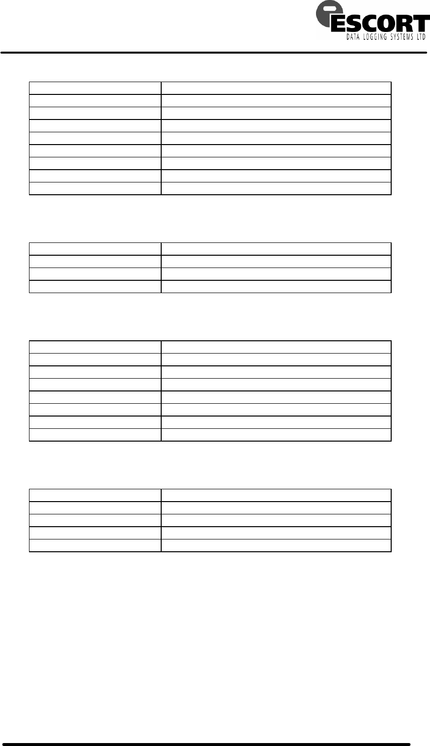
6.2 Main state
The Main display state shows which step in the program the logger is up to (including the latest
measurement if the logger is currently logging), as well as 'HIGH ALARM 1' if an over
temperature alarm has been triggered, and 'LOW ALARM 1' for the under temperature alarm.
When the logger has a program loaded and is ready to start the following is displayed.
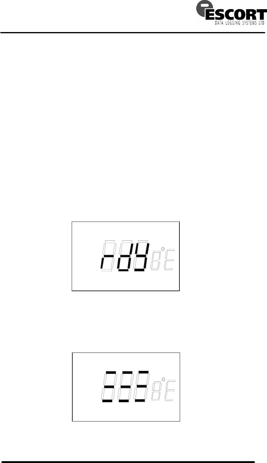
When the logger latches the start command (push button pressed and held for more than one
second) the following pattern is displayed for more than 1 second and less than 2, then the
logger will either begin logging if the DelayedStart register is set to 0 or enter the delayed start
mode if not.
LCD Mini ("The Intelligent")
TECHNICAL MANUAL
ESCORT DATA LOGGING SYSTEMS Ltd 2004 21/9/05 V1.0e Page 17
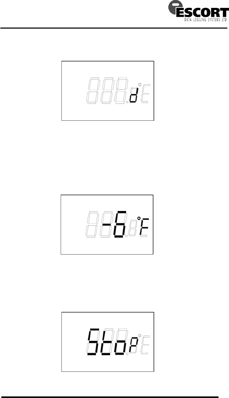
When the logger has been activated and is in the delayed start mode the following pattern is
displayed.
When the logger is in its active logging mode the latest temperature reading is displayed as
shown. 'High Alarm 1' and/or 'LOW ALARM 1' will be displayed if the respective alarm is
triggered. A low alarm condition has been shown.
When in this mode the word 'LAST' will flash at a one-second rate to indicate activity.
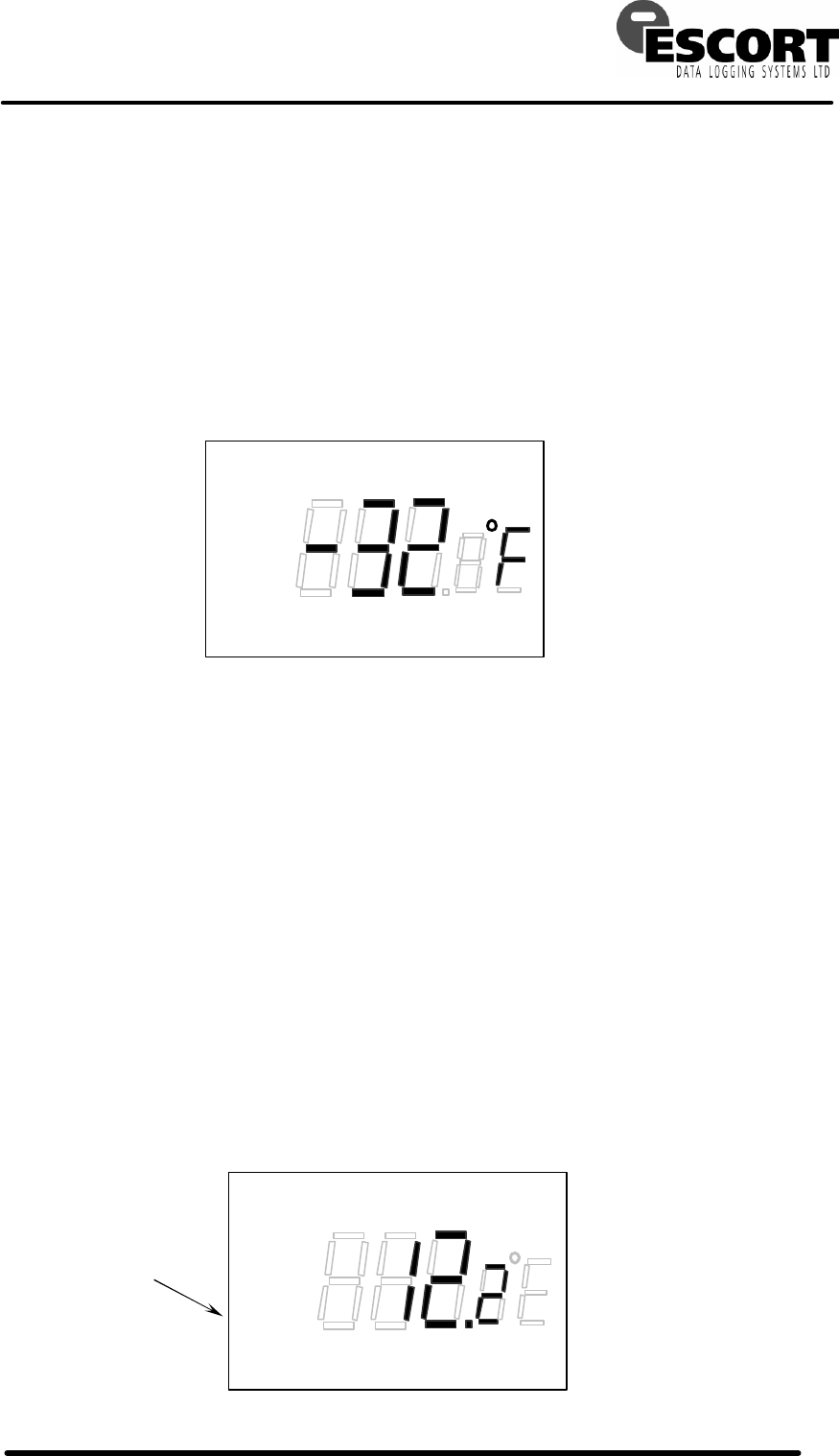
When the logger has finished its program and has stopped logging the following pattern is
displayed. If an alarm condition occurred and was latched during logging, it will continue to be
displayed. A low alarm condition has been shown.
LOW ALARM 1
LOW ALARM 1
LOW ALARM 1
LAST
LCD Mini ("The Intelligent")
TECHNICAL MANUAL
ESCORT DATA LOGGING SYSTEMS Ltd 2004 21/9/05 V1.0e Page 18
6.3 Statistics State
The statistics display state shows the highest temperature recorded, the lowest temperature
recorded and the average temperature over the entire journey. The display will continuously
cycle through the three pieces of information, displaying them for two seconds each. The lowest
reading has been shown.
Readings taken during background logging, if enabled, are not included in the statistics.
The user is not inhibited from cycling through the three display states prior to activating the
program. In this case, the initialised values of 0 °F for average temperature, -40 °F for highest
temperature and 158 °F for lowest temperature will be displayed.
6.4 Alarms State
The alarm display state shows the total time that the logger has spent at temperatures above
the high alarm level and below the low alarm level. This includes the time prior to either alarm
being tripped. The display will continuously cycle through the two pieces of information,
displaying them for two seconds each. When the time spent over temperature is displayed the
words 'HIGH ALARM 1' are shown, and the words 'LOW ALARM 1' are shown when the under
temperature time is displayed.
The time is displayed in hours with the fractional digit representing 10-minute intervals; e.g. the
following example shows 12 hours and 20 minutes. The time is always rounded down so this
example indicates a time between 12:20 and 12:29 inclusive.
If the high alarm is not enabled then the time spent over temperature remains unchanging at
000.0. The same applies for the low alarm.
The longest time that can be displayed is 999.5 hours or 41? days. Times longer than this are
displayed unchanging as 999.5.
LOW ALARM 1
LOWEST
HIGH ALARM 1
LOW ALARM 1
This will be
moved and
changed to say
"HOURS"

LCD Mini ("The Intelligent")
TECHNICAL MANUAL
ESCORT DATA LOGGING SYSTEMS Ltd 2004 21/9/05 V1.0e Page 19
Appendix A
A.1 EEPROM Memory Map.
Location Size Name Description / Format
0 ($00) 16 Description text Owner or Cargo Description.
16 ($10) 1 LogInterval Log interval in minutes ( 1-255, 0=256 )
17 ($11) 1 UpperAlarmLevel Byte value of upper specification alarm trigger
18 ($12) 1 LowerAlarmLevel Byte value of lower specification alarm trigger
19 ($13) 1 CaseType Lower nibble only used
0 = DataSource
1 = Mini
20 ($14) 3 StartLogTime Time that the first log was taken (3 bytes of
minutes count - MSB @ $16)
23 ($17) 2 NumberOfLogsToTake Word indicating the number of logs to take - does
not include background logging
25 ($19) 2 NumberOfLogsTaken The number of logs taken so far (not including
background logs)
27 ($1B) 1 LogStatus bit 7 - Celsius ( 1 = °C, 0 = °F )
bit 6 - Wrapped ( 1 = memory has wrapped )
bit 5 - LogStartType ( 1 = button, 0 = PC/CR )
bit 4 - ReadDelay (internal flag)
bit 3 - NotStopped ( 0 = stopped )
bit 2 - NotCurrentlyLogging ( 0 = actively logging )
bit 1 - ProgramRunning ( 1 = logging or delay )
bit 0 - NotBackgroundLogging ( 0 = BGL )
28 ($1C) 2 CurrentLogAddress The address in EEPROM where the next log to be
taken should be stored
30 ($1E) 2 FirstLogAddress The address in EEPROM where the first log was
stored (not including background logs)
32 ($20) 1 AlarmControl bit 7 - NotPreviousLogUnder ( internal flag )
bit 6 - NotPreviousLogOver ( internal flag )
bit 5 - NotLowAlarmOn ( 0 = low alarm triggered )
bit 4 - NotHighAlarmOn ( 0 = high alarm triggered)
bit 3 - ConsecDisable ( 0 = enabled )
bit 2 - Non-consecDisable ( 0 = enabled )
bit 1 - LowerAlarmEnable ( 1 = enabled )
bit 0 - UpperAlarmEnable ( 1 = enabled )
33 ($21) 1 AlarmDelays Nibble orientated register for Number of logs in
alarm before alarm generation.
Upper Nibble Non-consecutive alarm delay (1-15)
Lower Nibble: Consecutive alarm delay (1-15)
34 ($22) 1 UpperAlarmCounts Nibble orientated register to record the number of
logs so far for upper alarm generation.
Upper nibble Non-consecutive alarm count (0~15)
Lower nibble: Consecutive alarm count (0~15)
35 ($23) 1 LowerAlarmCounts Same as upper alarm counts but for the lower
alarm.
36 ($24) 3 TimeOverTemperature Sum of the time spent above the upper alarm level.
BCD-ish format.
$24 - minutes units (0 - 9)
$25 lower nibble - minutes tens (0 - 5)
$25 upper nibble - hours units (0 - 9)
$26 lower nibble - hours tens (0 - 9, "A" = blank)
$26 upper nibble - hours hundreds (0 - 9, "A" =
blank))

LCD Mini ("The Intelligent")
TECHNICAL MANUAL
ESCORT DATA LOGGING SYSTEMS Ltd 2004 21/9/05 V1.0e Page 20
39 ($27) 3 TimeUnderTemperature Sum of the time spent under temperature - format
as per time over temperature.
42 ($2A) 1 HighestLog The highest log recorded so far (not including
background logs)
43 ($2B) 1 LowestLog The lowest log so far (not including BGL)
44 ($2C) 1 AverageLog The average of all the logs taken so far (not
including BGL)
45 ($2D) 3 SumOfAllLogs The binary sum of all the logs taken so far (not
including BGL) - used in the average calculation
48 ($30) 1 StartDelay Start up delay for log start after button pressed.
0 = no start delay. 1-255 = delay in minutes.
49 ($31) 1 UserFlags bit 7 - 1 = Description is protected (not editable)
bit 6 - Data protected by PIN
bit 5 - Program protected by PIN
bit 4 - 1 = Sensor is "external"
bits 0-3 - UDATA version = 0
50 ($32) 1 LeaseControl bits 0-6 - 7 bit cycle count value
bit 7 - 1 = Lease logger, 0 = not lease.
51 ($33) 1 TimeZone bit 7 - 1 = Enabled
bit 6 - Daylight saving in sender time zone
bits 0-5 - Signed number of 30min intervals from
GMT for sender
52 ($34) 4 SerialNumber Format: DL-YY-DDD-III
Of the 32 bits with MSB at $37;
Bit 31 = 0 for DataSource (DL), 1 for Mini (MI)
Bits 24 to 30 = year code (00 - 99)
Bits 12 to 23 = day of year (1 - 366)
Bits 0 to 11 = index (0 - 999)
All fields are binary (not BCD).
Year portion of serial number is displayed in user software
as ‘AI’ for 98,AJ for 99,BA for 00, BB for 01, CA for 10 etc.
56 ($38) 2 SecurityCode Four-digit BCD number to protect against
unauthorised access.
58 ($3A) 1 SUM_INC Summary Increment, unsigned value
59 ($3B) 1 BattTypeAndRF Lower nibble frequency,
0=non-RF, 1=916, 2=868, 3=433MHz
Bit 7 battery type:
0=coin, 1=½AA
60 ($3C) 1 Battery usage counter
(LSB) 0=new battery
( Only for Intelligent Min )
For Intelligent Mini:
Battery usage counter
(MSB)
61 ($3D) 1
For Wireless Mini:
PIC firmware version 0x17 = version 1.7 etc.
62 ($3E) 2 TripCount Trip counter - incremented by software
64 ($40) 116 Look up table Used in ADC conversion to linearise thermistor and
convert its resistance to temperature
(See appendix C for specific values)
180($B4) 1868 Log buffer start The recorded data
NOTE: All multi-byte quantities are orientated with the MSB at the highest address.
NOTE: Shading in cells means that these locations are read into RAM by clearing the
"NotSemiInit" flag. (StartDelay $48 is also copied if bit 4 ReadDelay in LogStatus is set.)

LCD Mini ("The Intelligent")
TECHNICAL MANUAL
ESCORT DATA LOGGING SYSTEMS Ltd 2004 21/9/05 V1.0e Page 21

LCD Mini ("The Intelligent")
TECHNICAL MANUAL
ESCORT DATA LOGGING SYSTEMS Ltd 2004 21/9/05 V1.0e Page 22
A.2 RAM Memory Map
Note size and location refer to nibbles not bytes.
Location Size Name Description / Format
$80 12 Temp0 - Temp11 Temporary working registers.
$8C 2 C400kHz Two nibbles used to calibrate the 2400-baud
comms timing.
$8E 2 DelayedStartCounter Counter used to count down the number of
minutes until the next log.
$90 2 SecondsCounter0 Seconds counter for RTC - rolls over to zero
after counting to 59.
$92 2 SecondsCounter1 Additional seconds counter to synchronise
logging with the press of the button.
$94 6 TimeNow 3 byte sum of minutes for RTC.
$9A 2 Log interval RAM image of what's stored in EEPROM.
$9C 2 UpperAlarmLevel RAM image of what's stored in EEPROM.
$9D 2 LowerAlarmLevel RAM image of what's stored in EEPROM.
$A0 2 AlarmControl RAM image of what's stored in EEPROM.
$A2 2 LogStatus RAM image of what's stored in EEPROM.
$A4 1 ActionFlags0 bit 3 - BeginProgram
bit 2 - NotSemiInit
bit 1 - NotIncomingComms
bit 0 - NotTakeALog
$A5 1 ActionFlags1 bit 3 - BatteryStatus (not an action, 1 = OK)
bit 2 - NotFirstLog (internal, never clear this)
bit 1 - spare
bit 0 - NotCheckBattery
$A6 2 LatestLog The latest log reading.
$A8 1 DisplayFlags0 Display mode -
0 = Main, 1 = Stats, 2 = Alarms
$A9 1 DisplayFlags1 Display cycling
bit 3 - spare
bit 2 - 1 = upper alarm, 0 = lower alarm
bit 0,1 - 0 = Avg, 1 = Highest, 2 = Lowest
$AA 1 DisplayFlags2 bit 3 - DisplayDataNotValid
bit 2 - NotUpdateDisplay
bit 1 - Positive ( ± for displaying numbers )
bit 0 - Flash ( the 'LAST' word )
$AB 1 Counter General purpose counter
$AC 2 FirmwareVersion Upper nibble - f/w revision
Lower nibble - f/w sub-revision
$AE 2 ButtonAndDisplayTimer Controls automatic cycling of the display as
well as timing how long the button is pressed
for.
$B0 32 ByteStore0.0 - 16.1 RAM area where comms packets are
assembled as well as I2C transfers and a few
other things.
$D0 48 stack Do NOT write to here.
$FF end of RAM
NOTE: All multi-nibble quantities are orientated with the most significant nibble at the highest
address.

LCD Mini ("The Intelligent")
TECHNICAL MANUAL
ESCORT DATA LOGGING SYSTEMS Ltd 2004 21/9/05 V1.0e Page 23
Appendix B - ADC operation
The analogue to digital conversion is performed internal to the microcontroller by an oscillation
process. The basic procedure is
• A precision reference resistor and a capacitor are switched into the feedback path of a digital
oscillator.
• The oscillator is set running with the resistor and capacitor establishing the frequency.
• A defined number of cycles of this frequency (in this case 3000 cycles) sets a gate time
during which cycles of the 32768Hz clock are counted.
• The precision resistor is then switched out of the circuit and the thermistor is switched in.
• The cycle count from the first measurement is then used to set the gate time for a second
measurement. This time the gate time is based on the 32768Hz clock.
• The number of cycles of the ADC oscillator is now counted over this time and this count is
inversely proportional to the resistance of the thermistor.
The maths of this are shown below:
FirstGateTime = (RRef x C x 2.2) x 3000
Counter A = 32768 x FirstGateTime
SecondGateTime = 1/32768 x CounterA
Counter B = SecondGateTime / (RTherm x C x 2.2)
= 1/32768 x CounterA / (RTherm x C x 2.2)
= 1/32768 x 32768 x FirstGateTime / (RTherm x C x 2.2)
= 1/32768 x 32768 x (RRef x C x 2.2) x 3000 / (RTherm x C x 2.2)
= (RRef x C x 2.2) x 3000 / (RTherm x C x 2.2)
= (RRef x 3000 ) / RTherm
RTherm = (3000 / Counter B ) x RRef
Note: The "2.2" is just a constant relating to the mechanics of the oscillator - it gets divided out.
C = 1000pF.
The resistance of the thermistor ranges from 2kΩ at 70°C to 335kΩ at -40°C so in practice in
order to maintain accuracy over the whole range two conversions are sometimes taken. An
initial gate time of 3000 cycles is used and if the final count comes out less than 4096 then the
conversion is done a second time using an initial gate time of 12000 (4 x 3000).
At no stage is R
Therm actually calculated. Instead, a look up table is used to convert the final
count straight to temperature. The index to the LUT is the temperature in degrees Fahrenheit (or

LCD Mini ("The Intelligent")
TECHNICAL MANUAL
ESCORT DATA LOGGING SYSTEMS Ltd 2004 21/9/05 V1.0e Page 24
Celsius) and the table holds word values corresponding to the expected final count. Just to
complicate things (and reduce the size of the table) every fourth degree F (or every second
degree C) is stored and temperatures in between are linearly interpolated. For example, the
word stored at LUT index 1 is 430 corresponding to -40°F, and the word stored at LUT index 2 is
495 corresponding to -36°F. A final count of 440 is therefore found to correspond to -39°F.
The equation given by OKI for calculating the resistance of the thermistor as measured by their
internal ADC circuit is approximate and although highly accurate mid range, is as much as 7%
out at the extremes of the range. Due to this (and also heavily implied by their documentation)
the translation from the ADC count number to an actual temperature reading has been worked
out empirically.
The look up table has been stored in EEPROM and can be reloaded at any stage. It appears,
based on just the few sample devices tried so far, that only one standard LUT for Fahrenheit and
one for Celsius will be needed, however if production spread is larger than expected then each
logger can be individually calibrated. This can be achieved by a 10 second automated process
in which perhaps three precision resistance values are measured and a table is chosen from a
suite of pre-calculated tables based on the readings obtained. Down load time for the table as
well as other initialisation data is around 3 seconds.
There is a spare byte in EEPROM that can be used to record which table is required if a user
wishes to change between the units on the fly.
At the completion of an A/D conversion the RAM locations Temp8, Temp9, Temp10 & Temp11
hold the raw count. An immediate conversion can be triggered by loading the
DelayedStartCounter with 0 and the SecondsCounter1 with 59 while ensuring the logger is in its
active logging mode.

LCD Mini ("The Intelligent")
TECHNICAL MANUAL
ESCORT DATA LOGGING SYSTEMS Ltd 2004 21/9/05 V1.0e Page 25
A.3 ADC Look-up tables
Address
°C count
°C
°F count
°F
0040
0000
< -40
0000
< -40
0042
01AE
-40
01AE
-40
0044
01E9
-38
01EF
-36
0046
0229
-36
0238
-32
0048
0271
-34
0289
-28
004A
02C0
-32
02E5
-24
004C
0319
-30
034D
-20
004E
037B
-28
03BF
-16
0050
03E6
-26
0440
-12
0052
045D
-24
04D1
-8
0054
04E2
-22
0575
-4
0056
0575
-20
062A
0
0058
0618
-18
06F5
4
005A
06CD
-16
07D4
8
005C
0791
-14
08D1
12
005E
086C
-12
09EA
16
0060
095D
-10
0B1A
20
0062
0A64
-8
0C6B
24
0064
0B7F
-6
0DEB
28
0066
0CB8
-4
0FA2
32
0068
0E17
-2
10D8
36
006A
0FA2
0
12B9
40
006C
10B9
2
14C6
44
006E
1259
4
1711
48
0070
1429
6
1984
52
0072
1626
8
1C36
56
0074
184B
10
1F27
60
0076
1A98
12
2265
64
0078
1D18
14
25ED
68
007A
1FCD
16
29BB
72
007C
22C0
18
2DE3
76
007E
25ED
20
3242
80
0080
295A
22
36EE
84
0082
2D0E
24
3C00
88
0084
30F2
26
416F
92
0086
3510
28
4750
96
0088
3977
30
4D92
100
008A
3E2C
32
5475
104
008C
4332
34
5B9A
108
008E
4890
36
6339
112
0090
4E42
38
6B5E
116
0092
5475
40
7400
120
0094
5AE3
42
7D35
124
0096
61B3
44
8707
128
0098
68EC
46
9152
132
009A
708C
48
9C5F
136
009C
789A
50
A7BE
140
009E
8123
52
B3FB
144
00A0
8A1E
54
C0A6
148
00A2
9388
56
CE54
152
00A4
9D82
58
DC8F
156
00A6
A7BE
60
EB53
160
00A8
B2C2
62
FFFF
> 160
00AA
BE1D
64
FFFF
00AC
CA3A
66
FFFF
00AE
D6DE
68
FFFF
00B0
E3F1
70
FFFF
00B2
FFFF
> 70
FFFF

LCD Mini ("The Intelligent")
TECHNICAL MANUAL
ESCORT DATA LOGGING SYSTEMS Ltd 2004 21/9/05 V1.0e Page 26
Values are in hexadecimal. MSB is at higher address.
LCD Mini ("The Intelligent")
TECHNICAL MANUAL
ESCORT DATA LOGGING SYSTEMS LTD 2004 DATED:12th May 2004 PAGE 27
Appendix C - Firmware revision history
F/W
Ver
sub
ver
Release
Date
Products Supported
Primary Revision Purpose
Hex
File name
Hex
Chksum
µP
PCB
revisions
1
1 1 2002 all Initial '162A •
TBR = yet to be released M = Can be used with modified PCB