Escort Data Logging Systems MINI PORTABLE DATA LOGGING DEVICE User Manual Wireless Mini technical manual v1 3
Escort Data Logging Systems Ltd PORTABLE DATA LOGGING DEVICE Wireless Mini technical manual v1 3
Contents
- 1. USERS MANUAL
- 2. TECHNICAL MANUAL
- 3. QUICK REFERENCE GUIDE
USERS MANUAL
Wireless Mini
Technical manual
Implant
Rev 1.2
Revision History
Rev 1.0 - WCH 25/5/5
Rev 1.1 - WCH - 2/8/5
Rev 1.2 - WCH - 13/9/5
Rev 1.3 - WCH - 29/11/5
This manual covers the functionality of the RF circuitry (referred to as 'The
RF Implant') in the Wireless Mini. For details of the logger circuitry and
functionality please refer to the LCD Mini technical manual.

1
- Contents -
1.0 General description
1.1 Sleeping & Waking
1.2 Interfacing to the host system
1.3 Battery measurement
1.4 Local copies of information
1.5 In circuit serial programming
2.0 RF description
2.1 Hardware
2.2 Packet structure
2.3 Resynchronisation
3.0 Packets and Protocols
3.1 Packet formats
3.2 Specific packet types
3.3 Establishing communications
3.4 Reading data from a logger
3.4.1 The read process
3.4.2 Packets associated with reading the log buffer
3.5 Writing to a logger
3.5.1 The Write process
3.5.2 Packets associated with the write process
3.5.3 The program data structure
3.5.4 Restarting loggers with version 1.6 firmware
3.6 Security settings and Lease count
3.7 Status request
4.0 Code description
4.1 Breaking out of non-terminating loop
5.0 Memory map
5.1 Constants
2
Revision History
1.2 Status Reply packet type corrected (was 0x14, now is 0xF1)
1.3 GoToSleep packet introduced (packet 0x18)
3
1.0 General description
The Wireless Mini is designed around the LCD Mini. In essence it incorporates a complete LCD Mini
logger with an "RF Implant" attached. The code and functionality of the logger part are identical to the
LCD Mini and the Implant simply allows data to be extracted via RF rather than direct connection. To this
end the original code running on the Oki processor of the LCD Mini is 'unaware' of the RF circuitry and
makes no allowance for it. The Implant, which is based around a PIC microcontroller, must trick the Oki
processor into leaving the EEPROM alone when it wants to access it. This is detailed in section 1.2.
The RF circuitry consists of two main blocks namely a PIC microcontroller and an RF transceiver (RFM
TR1000/TR1001). This technical manual will discuss this circuitry and refer to it as the "Implant". For
details of the logger part of the product please refer to the LCD Mini technical manual.
The Implant has been designed so that it may be converted to add RF functionality to other products (e.g.
iLog). It has been designed to be highly portable although some code modification will inevitably be
necessary.
The Implant is designed to be part of a multi-node network with one Master and many loggers. Obviously
only one device can be transmitting at any one time but all loggers will be listening to all packets and will
respond when uniquely addressed. The unique address is based on the logger's type and serial number.
1.1 Sleeping & Waking
To be able to provide high speed communication over a respectable range the RF Implant processor must
run at 4MHz and the RF receiving circuitry must be very sensitive, however the whole system must also
draw less than 100uA. To achieve this it spends most of the time sleeping then for 4ms every 1/3 of a
second it wakes up and listens for signal. If it receives a valid signal it will enter 'Active' mode where it is
continuously listening.
The cyclic wake up circuitry is simply a capacitor charging through a resistor (R23 and C15 on Rev 1.0
schematic). When the voltage on the cap. passes a threshold it triggers an interrupt to the PIC which pulls it
out of sleep mode. The PIC in turn pulls the transceiver out of sleep mode and begins listening. At the same
time it discharges the capacitor through R24. If a valid signal is not received within 4ms then the now
discharged capacitor is released to begin charging again, the PIC goes to sleep and cycle repeats.
A valid signal is defined as a complete WakeUp packet. The protocols are defined in Section 3.0. When
another device, the Master, wants to find out what loggers are within range it broadcasts a series of Wake
Up packets to all loggers. All loggers within range should hear at least one of these and enter Active mode.
With the loggers attention it then broadcasts WhosThere? and the loggers reply in randomly selected time
slots.
The loggers identify themselves using a unique address and from then on the Master uses this to direct
commands to individual loggers.
While in active mode, if the logger does not detect any valid packets for a period of 60s then it switches
back to its low power mode and begins the sleeping / waking process again.
1.2 Interfacing to the host system
The LCD Mini was designed to communicate with other devices via RS232 at 2400 baud. This is far too
slow for the purposes of radio communication. To get around this the Implant uses direct memory access to
4
the EEPROM. This however requires a trick because the Oki processor is unaware of the Implant so makes
no allowance for memory sharing. Fortunately the Oki code will not access EEPROM when it is in 'comms
mode'. When the Oki processor gets a message via RS232 it finishes any activities it is part way through
then enters comms mode. While in this mode it does nothing more than monitor the comms lines and
update its RTC. If there is no activity on the RS232 lines for 800ms or more then it resumes normal
operation.
When high speed reading of the EEPROM data is required, the Implant exploits this functionality by
sending a message via RS232 to the Oki processor. Once it is satisfied that the Oki processor has entered
comms mode, it directly accesses EEPROM at high speed. Each block of 64 data bytes is transferred to
local PIC RAM, assembled into a packet then transmitted out over the RF link. After a valid 'Ack' is
received from the Master the next packet is retrieved, assembled and sent.
Because the Oki processor was originally set up to be the exclusive master on the I2C bus it is necessary to
convert the the output driving the SCL line into an open collector port before attempting to drive it with
another processor. This is done using two schottkey diodes (D2 & D7 on rev 1.0 schematic). In the same
way the RS232 is driven as open collector with the PC driving Q4 and the PIC driving Q7.
There are other blocks of information which can be read once, when no RF activity is occurring, and stored
for later (such as the loggers serial number) and the Implant simply uses the normal RS232 channel for this.
There are further pieces of information such as the loggers current logging state which need to be read in
real time but don't require DMA and again the RS232 channel is used for this.
If a PC is trying to access the logger via RS232 at the same time as the Implant then there will be
contention. This is unavoidable but will be detected by corruption of the check-sum. To alleviate any
problem here the Implant will refuse to operate if the logger is connected to a PC. It monitors the power
supply to the RS232 circuitry (through the voltage divider R28 & R29 on rev 1.0 schematic) and if this is
on then it will switch from active mode to sleeping/waking mode (if active to start with) and will not
respond to any 'WakeUp' commands that are broadcast.
1.3 Battery measurement
The battery measurement of the Wireless Mini logger is based on battery voltage and is simply a Good/Bad
measurement.
The battery measurement circuit in the original LCD Mini is reasonably poor. It is only approximate at
room temperature and changes significantly with temperature. This has not been a major problem with this
logger as the battery can only be measured when the LCD Mini logger is connected to a PC and this
generally is at room temperature.
With the inclusion of RF communication the logger may now report its battery status when the logger itself
is at any temperature in its range. To ensure an accurate measurement the Implant uses a separate circuit
based around a dedicated IC. This device, U3 - TC54, will output a high voltage when its input is greater
than 2.7V and a low voltage when its input is less than 2.7V. The output of this device is connected to an
input on the PIC.
In addition to this there is a voltage divider at the input of the device (R33 & R34) which divides down the
battery voltage. Every time the Implant reads the battery level it switches this divider in, reads the level,
then switches this divider out to save current. The values of the resistors can be adjusted to set the level at
which the battery is considered to be getting low.
The battery is measured every time a Status packet is requested.

5
Note that the Oki processor still uses the original method of measuring the battery level. Although checked
for accuracy in the factory it is possible that the two battery level circuits may report conflicting levels.
Note also that irrespective of the remaining energy, the voltage on the battery will vary significantly with
temperature.
1.4 Local copies of information
To ensure a high speed response the Implant must reply to any requests from the Master as soon as it can
(within a few milliseconds if possible). As mentioned in section 1.2 the Oki processor only communicates
via RS232 at 2400 baud. In addition to this there may be as much as 1.5 seconds delay before it enters
comms mode after receiving an RS232 packet. Due to this the Implant makes local copies of some of the
logger information so that it can provide expedient replies to any Master that is talking to it. The most
notable of these is the serial number. Immediately after power up the Implant reads the loggers serial
number (via the RS232 channel) and stores it in local RAM. From then on it uses this as part of its unique
address.
The Implant has an input which tells it if the logger is connected to a PC or not. If the Implant detects that it
is then it will begin monitoring the line. After 2 seconds of inactivity from the PC the Implant will ma ke a
local copy of the security settings. When an attempt is made to restart or reprogram the logger via RF then
these local settings are used to allow or deny the command.
Note that it is possible to change a loggers serial number by writing to EEPROM while the local copy in
the Implant remains unchanged. This could cause great confusion. To avoid this it is necessary to power
cycle the logger any time its serial number is changed.
Variable that is copied When it is copied
Serial number Immediately after power up
After a watch dog restart
Case type Immediately after power up
After a watch dog restart
Oki code f/w version Immediately after power up
After a watch dog restart
Lease state Immediately after power up
After a watch dog restart
2s after PC comms cease (f/w version 1.7+ changes this to 1s)
When requested by a 'CheckLeaseState' packet
User flags Immediately after power up
After a watch dog restart
2s after PC comms cease (f/w version 1.7+ changes this to 1s)
Security code Immediately after power up
After a watch dog restart
2s after PC comms cease (f/w version 1.7+ changes this to 1s)
Table of local copies of logger information
1.5 In circuit serial programming
At this stage the Implant is not specifically set up for ICSP however the PIC processor supports this and the
PCB can also accommodate it.
6
Removing R44 and installing D11 will isolate the supply and with a suitable clip to go over the PIC
processor ICSP can be implemented. D10 will isolate Vpp from the rest of the circuitry. Initially the supply
line of the PIC is connected directly to the power supply simply to remove a diode drop and increase
reliability under low battery conditions.
7
2.0 RF description
2.1 Hardware
The RF Implant uses Amplitude Shift Keying (ASK) i.e. a logic high is represented by a high amplitude of
the RF frequency and a logic low is represented by a low (but not zero) amplitude of the RF frequency.
The ASK drive signal that the transceiver module requires is a current based signal and must switch
between a higher current and a lower (but non-zero) current. This is produced by two digital outputs from
the PIC microcontroller (RA1 & RB5). These two outputs have weighted resistors and the current is
switched to high with both outputs high and low with RA1 low and RB5 high. Both outputs sit low when
not transmitting.
The data rate is 83k333 baud which is exactly 12us per transmitted bit.
Manchester encoding is used so every bit is sent as two 'transmitted bits', first the bit itself then second the
inversion of the bit. This keeps the signal DC balanced (a requirement of the transceiver) and allows for
100% error checking.
The data flow, for obvious reasons, is half duplex. The transceiver module must be switched between
transmit and receive mode depending on the data direction. This is achieved by RB6 & RB7. Both low turn
the transceiver off. Both high put the transceiver in receive mode. RB6 low and RB7 high put the
transceiver into transmit mode.
The transceiver simply converts the current into its digital input to RF energy when transmitting or the RF
energy (after automatic gain adjustment) into a voltage at its digital output when receiving. It does not
attempt to interpret or encode the data bits. To this end there is no auto detection interrupt when in receive
mode so the PIC must be checking the data (or noise) stream when it is expecting a packet. The data bits
are bit-bashed both in the Implant and in the REDi.
The data rate is independent of the RF frequency. Initially there are two RF frequencies namely 916MHz
for the US market and 868MHz for the European market. The oscillator for the specific frequency is built
into the transceiver so to convert a logger from one frequency to the other would require changing the
transceiver. No PIC firmware changes would be required.
With the inclusion of L2 (10nH) and L3 (100nH) inductors at the RF I/O pin of the transceiver, the module
is matched for a 50Ω real impedance. The network L4 and C26 is required to match the antenna itself to
this impedance.
The sensitivity of the receiver is 91dBm.
The power of the transmitter is 1.5dBm.
This, given the losses in the system, allows for a transmission range of around 50m outdoors.
8
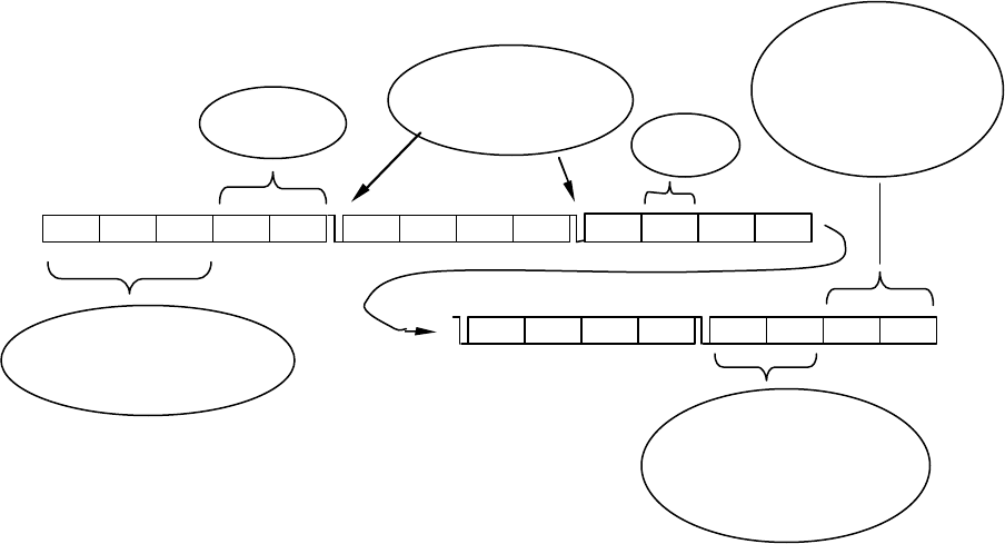
2.2 Packet structure
The data is clocked LSB first.
The diagram below shows a command packet ..
The Implant first polls for at least 11 bits of the preamble then for an exact match of the start character
(refer to section 5.1). If this match is found then it continues to clock in the rest of the packet. As it does
this it checks each bit for correct Manchester encoding and aborts if it sees corruption. Finally it checks the
checksum then processes the packet.
The logger type and serial number form a unique address. The serial number is simply a copy of the loggers
electronic serial number and the LType is a number referring to the product. For all transfers this is used to
identify the logger that is being addressed or is replying. The assumption is that there is only one Master
and it is always part of the communications. Attempting to use two REDi Masters at once will lead to
interference and failure to communicate. Interlaced use of two REDi Masters in the same proximity should
work as expected.
For a general broadcast to all loggers the address 0xFF,0xFF,0xFF,0xFF,0xFF is used.
The packet type identifies the purpose of the packet. The packet length can be inferred from this although
in practice the Implant (or REDi) will be expecting a certain type of packet and assumes the length before it
begins clocking bits in. This is done because the processor is not powerful enough to decode the packets on
the fly. If a longer or shorter than expected packet is sent then the check sum will not add up and the packet
type will be wrong leading to the packet being rejected.
The Data section is the relevant content of the packet and varies from packet to packet. This is detailed on
the following pages.
The Checksum is the check sum for the whole packet excluding the preamble. It is a 16 bit Fletchers check
sum. This is not as robust as CRC but is significantly faster to generate and check and in fact is barely
necessary given the inherent error checking properties of Manchester encoding.
0xAA 0xAA 0xAA STX0 STX1 LType
S/N S/N S/N S/N Data Data PType
Data Data Data Data FCS0 Padding Padding
FCS1
Preamble to condition the
Automatic Gain Circuits
16 bit start
character
Resynch
ronisation
edges to ensure bit
timing is accurate
Packet
type
Check sum. Fletchers
used because it is fast
- most error checking
done on a per bit basis.
To simplify the
coding packets are
always multiples of 4
bytes plus one 5 byte
block.
9
2.3 Resynchronisation
Although Manchester encoding inherently contains a clock signal the processors (PIC and M16) are not fast
enough to extract this on the fly and use it to adjust their timing. To this end the signal is treated as
asynchronous and the timing is based around the system crystal. After every four bytes a synchronisation
edge is sent which is used to bring things back into line if there has been drifting. The calculation for this is
shown.
4 bytes x 8 symbols x 2 bits x 12us = 768us
1/2 bit width = 6us
6 out of 768 = 1 part in 128 = 7812ppm
if accuracy is 50ppm/ °C then :
-40°C to +25°C = 65°C x 50ppm/°C => 3250ppm = 0.21 bit width
absolute accuracy of ±50ppm at 25°C is of negligible importance (gets swamped by the drift)

10
3.0 Packets and Protocols
While the general structure of each packet is the same, several different packets have been defined based on
the length and type of data to be transferred. The packet types are shown below followed by tables of
specific packets.
3.1 Packet formats
Wake Up packet:
Field name # bytes
Field content
Preamble 3 0xAA,0xAA,0xAA
Start character 2 0x72, 0x65
Packet type 1 0x00 - Wake up
Check Sum 2 0x06, 0x22 - Fletcher
Command packet :
Field name # bytes
Field content
Preamble 3 0xAA,0xAA,0xAA
Start character 2
Recipient 5 TSSSS (Logger Type, Serial Number)
Packet type 1 Variable
Data 6 Always 6 bytes in length
Check Sum 2 Fletcher
Very Short Data Packet : 4224us
Field name # bytes
Field content
Preamble 3 0xAA,0xAA,0xAA
Start character 2
Logger / Recipient 5 TSSSS (Logger Type, Serial Number)
Packet type 1 0xF0
Data 6 Always 6 bytes in length
Check Sum 2 Fletcher
Short Data Packet :
Field name # bytes
Field content
Preamble 3 0xAA,0xAA,0xAA
Start character 2
Logger / Recipient 5 TSSSS (Logger Type, Seria l Number)
Packet type 1 0xF1
Data 32 Always 32 bytes in length
Check Sum 2 Fletcher

11
Long Data Packet :
Field name # bytes
Field content
Preamble 3 0xAA,0xAA,0xAA
Start character 2
Logger / Recipient 5 TSSSS (Logger Type, Serial Number)
Packet type 1 0xF2
Data 48 Always 48 bytes in length
Sequence 4 Packet number (LSB first)
Check Sum 2 Fletcher
Very Long Data Packet : 16464us
Field name # bytes
Field content
Preamble 3 0xAA,0xAA,0xAA
Start character 2
Logger 5 TSSSS (Logger Type, Serial Number)
Packet type 1 0xF3
Data 64 Always 64 bytes in length
Sequence 4 Address where this data has come from (LSB first)
Check Sum 2 Fletcher
Single Byte Reply :
Field name # bytes
Field content
Preamble 3 0xAA,0xAA,0xAA
Start c haracter 2
Logger 5 TSSSS (Logger Type, Serial Number)
Packet type 1 Variable (Ack, Nack etc.)
Check Sum 2 Fletcher

12
3.2 Specific packet types
REDi to Logger
Name Packet ID
(PType) Packet
Type Recipient Data Description
Wake Up 0x00 Wake up Non specific none Broadcast over and over for 1
second to wake up all loggers.
Ack 0x01 Single Byte
Reply TT,SN,SN,SN,SN none Acknowledgement of correct
reception of a packet.
Resend 0x02 Single Byte
Reply TT,SN,SN,SN,SN none Request for a retransmission of
the last packet.
Who's There ? 0x11 Command 0xFF,0xFF,0xFF,
0xFF,0xFF all blank Request for loggers to identify
themselves.
Don't reply to
"Who's There
?"
0x11 Command TT,SN,SN,SN,SN all blank Tells the specified logger not to
reply to the general "Who's
There ?" packet.
Read Data 0x12 Command TT,SN,SN,SN,SN D[0:2] : address to read
from
D[3:5] : length required
Request for the logger to begin
sending a series of data
packets.
Status Request 0x14 Command TT,SN,SN,SN,SN all blank Request for the loggers status
packet.
How much data
do you have ? 0x15 Command TT,SN,SN,SN,SN all blank Request for the size of data that
the logger holds.
Program
Logger
0x16 Command TT,SN,SN,SN,SN D0 : # of packets that
follow
D1 : flags
D[2:5] : security code
The command to initiate
reprogramming or restarting a
logger. "Logger Program"
packets may follow this.
Check Lease
Count 0x17 Command TT,SN,SN,SN,SN all blank Request for the logger to check
the lease count now.
Go To Sleep 0x18 Command TT,SN,SN,SN,SN
or
0xFF,0xFF,0xFF,
0xFF,0xFF
all blank Puts a specified logger or all
loggers within range to sleep.
(introduced after version 1.9
f/w)
Logger
Program 0xF2 Long Data TT,SN,SN,SN,SN See section 3.5 on
programming a logger. Data packets containing the
data and locations of a loggers
program.
Logger to REDi
Name Packet ID
(PType) Packet
Type Data Description
Ack 0x01 Single Byte
Reply none Acknowledgement of a correctly received
packet.
Nack 0x03 Single Byte
Reply none The packet was received but was not or cannot
be processed. [no longer used]
Bad Password 0x04 Single Byte
Reply none Reply when a "Program Logger" packet was
received and the logger required a password
and the password was incorrect.
Lease Expired 0x05 Single Byte
Reply none Reply when a "Program Logger" packet was
received but the logger's lease had expired.
Data Request
Reply 0xF3 Very Long
Data Packet 64 bytes of logger data A block of data read out of the logger's
EEPROM.
Data Size
Reply 0xF0 Very Short
Data Packet D[0:2] : data length
D[3:5] : start address Reply to the "How much data do you have ?"
packet.
Status Reply 0xF1 Short Data
Packet D[0:1] : Implant f/w
D[2:3] : Logger f/w
D4 : Case type
D[5:22] : Status packet
from host logger
Reply to a Status Request packet. See section
3.7.

13
D[23:end] : padding
All multi byte quantities have MSB at the highest address.
14
3.3 Establishing communications
The Master (REDi) transmits 'Wake Up' repeatedly for 1.0 second.
The logger listens for 4ms roughly every 330ms. The wake up packet takes 1.5ms to transmit so this
ensures a minimum potential of six 'Wake Up' messages received if within range.
For firmware verison 1.7+ the logger actually spends a few hundred microseconds prior to this analysing
the incident RF energy to determine if it looks like a stream of data at the correct rate. If it does then it
continues to poll for 4ms for a 'Wake Up' message. If it doesn't then it goes straight to sleep.
If the logger gets a 'Wake Up' packet it remains Active (listening) for the next 60 seconds. In fact it remains
active for 60s after the last valid packet it receives.
All loggers within earshot should now be Active (continuously listening).
If only new loggers are required then ...
The REDi scans its database and broadcasts 'Don't reply to "Who's There?"' to all known loggers
(whether in range or not). The 'Don't reply to "Who's There?"' command is identical to the 'Who's There?'
command except that the former has a specific address associated with it and the latter has the address
section set to all 0xFF to indicate a general broadcast. If a logger receives a 'Don't reply to "Who's There?"'
command (addressed specifically to it) then it will ignore any general broadcasts of 'Who's There?' for the
next two seconds.
The REDi then broadcasts a general 'Who's There?' command.
If the logger receives a 'Who's There?' command then it randomly selects a time slot (32 slots spaced 8ms
apart) and responds by transmitting three 'Ack' packets one after the other. The 'Ack' packets contain the
logger's type and serial number and uniquely identify that Logger.
If the REDi receives one or more of these packets then the logger is added to a list of 'Loggers within
range'.
After listening for 256ms (32 x 8ms) the REDi transmits the 'Don't reply to "Who's There?"' command to
each logger in the 'Loggers within range' list.
The REDi then broadcasts a second general 'Who's There?' command and the process is repeated. After this
a third cycle is performed.
After 1.77s the establish comms procedure is complete and we are ready to start transferring data from
individual loggers.
15
3.4 Reading data from a logger
3.4.1 The read process
To download the logger's log buffer the REDi controls a sequence of steps. The REDi always acts as the
Master and the logger as a Slave. If the REDi does not get a valid reply during any step it will retransmit
the request up to 15 times.
Step 1
The REDi first broadcasts a 'How much data do you have ?' command.
The logger responds with a 'Data Size Reply' packet containing the size and start address.
Step 2
The REDi then broadcasts a request for this much data.
The logger replies with an 'Ack'.
The logger also takes a snapshot of its internal status at this point.
Step 3
The REDi then transmits a 'Resend' command.
The logger responds by sending the first Data packet back.
If this is received correctly the REDi sends an 'Ack'.
If this is not received or is corrupt the REDi sends a 'Resend'.
If the logger gets a 'Resend' it sends the same packet again.
If the logger gets an 'Ack' it sends the next packet.
If the REDi sends an 'Ack' which the logger does not receive then, after not receiving the next data packet,
the REDi will follow this with a 'Resend' and will get the previous packet again (which was correctly
received last time). All packets have an associated sequence tag which alerts the REDi to ignore the second
transmission.
Both the logger and the REDi keep track of how many packets are sent. When the logger sends the last
packet (and gets a valid 'Ack') it simply stops and goes back to listening for Command packets.
Step4
The REDi sends a 'Status Request' command.
The logger responds with a 'Status Reply'.
Note: The REDi sends only a generic Ack to get the next packet instead of acknowledging each sequence
number and specifically requesting the next. This is to keep overhead to an absolute minimum.

16
3.4.2 Packets associated with reading the log buffer
How much data do you have ? (REDi to Logger) :
Field name # bytes
Field content
Preamble 3 0xAA,0xAA,0xAA
Start character 2 0x72, 0x65
Recipient 5 TSSSS (Logger Type, Serial Number)
Packet type 1 0x15
Data 6 0x00, 0x00, 0x00, 0x00, 0x00, 0x00
Check Sum 2 Fletcher
Data Size Reply (Logger to REDi) :
Field name # bytes
Field content
Preamble 3 0xAA,0xAA,0xAA
Start character 2 0x6C, 0x67
Logger 5 TSSSS (Logger Type, Serial Number)
Packet type 1 0xF0
Data 3
3
Data length (LSB first)
Data address (LSB first) (always EEPROM)
Check Sum 2 Fletcher
Read Data (REDi to Logger) :
Field name # bytes
Field content
Preamble 3 0xAA,0xAA,0xAA
Start character 2 0x72, 0x65
Recipient 5 TSSSS (Logger Type, Serial Number)
Packet type 1 0x12
Data 3
3 Data length (LSB first)
Data address (LSB first) (always EEPROM)
Check Sum 2 Fletcher
Data Request Reply (Logger to REDi) :
Field name # bytes
Field content
Preamble 3 0xAA,0xAA,0xAA
Start character 2 0x6C, 0x67
Logger 5 TSSSS (Logger Type, Serial Number)
Packet type 1 0xF3
Data 64 Data
Sequence 4 Address of data byte #1 in this packet (LSB first)
Check Sum 2 Fletcher

17
3.5 Writing to a logger
3.5.1 The Write process
The REDi sends a 'Program Logger' command which contains a security code.
If the logger is leased and the lease has expired then the logger replies with a 'LeaseExpired' packet and
returns to listening for command packets. In fact the lease count must be checked at the time of
reprogramming because the logger may be in the Ready or Logging state and this may affect whether it can
be reprogrammed. See section 3.6 for more detail. If the Master (REDi) gets a 'LeaseExpired' reply then it
should send an 'UpdateLeaseCount' packet then try the 'Program Logger' command again.
If the logger is password protected for programming and the security code does not match the loggers code
then it replies with a 'BadPassword' packet and returns to listening for command packets.
If the security code etc. is valid then the logger replies with an 'Ack'.
The logger then decodes the command packet to determine if there are packets to follow. There could be up
to 3.
If no further packets are expected then the logger gets on with processing the flags.
If further packets are expected then the REDi sends each one in turn.
The logger replies to each packet with an 'Ack' if received correctly.
Once all packets are received they are processed in reverse order. Packet #3 is processed first, then #2, then
#1 then the flags in the original command packet are processed.
For firmware version 1.7+ a flag called 'LastProgramOK' is cleared as soon as a 'Program Logger'
command is received. If the program gets correctly implemented (ie. the Oki processor acknowledges all
packets sent to it and the PIC code completes the reprogramming loop) then this flag is set. It is available in
the 'Status' packet and should be checked by the REDi Master after reprogramming a logger.
For firmware version 1.6 the REDi Master must read back the lower 64 bytes of EEPROM and check the
signature of the program to verify correct implementation.
3.5.2 Packets associated with the write process
The Program Logger packet
Field name # bytes
Field content
Preamble 3 0xAA,0xAA,0xAA
Start character 2 0x72, 0x65
Recipient 5 TSSSS (Logger Type, Serial Number)
Packet type 1 0x16
Data 6 [ Note 1 ]
Check Sum 2 Fletcher

18
Note 1 : Data structure
byte 0 number of packets to follow (only lowest 2 bits recognised so max. 3 packets)
byte 1 flags [ Note 2 ]
byte 2 SecurityCode#0
byte 3 SecurityCode#1
byte 4 SecurityCode#2 (not used in Wireless Mini)
byte 5 SecurityCode#3 (not used in Wireless Mini)
Note 2 : Flags
bit 0 Load default values into logger registers [ Note 3 ]
bit 1 Start the program waiting for button
bit 2 Simulate the press of a button to begin the program
bit 3 Spare
bit 4 0 (note these higher bits must be zero and cannot be used)
bit 5 0
bit 6 0
bit 7 0
Note 3 : The default values to load
NumberOfLogsTaken = 0x00 TimeOverTemperature = 0xAA,0xA0,0x00
CurrentLogAddress = 0x00B4 TimeUnderTemperature = 0xAA,0xA0,0x00
UpperAlarmCounts = 0x00 HighestLog = 0x00
LowerAlarmCounts = 0x00 LowestLog = 0xFF
AlarmControl = 0xF- SumOfAllLogs = 0x00,0x00,0x00
Followed by 0 to 3 Long Data Packet(s) :
Field name # bytes
Field content
Preamble 3 0xAA,0xAA,0xAA
Start character 2 0x72, 0x65
Logger 5 TSSSS (Logger Type, Serial Number)
Packet type 1 0xF2
Data 48 Always 48 bytes in length [ Note 4 ]
Reference 4 Packet number 0,1 or 2 (only one byte used)
Check Sum 2 Fletcher
Note 4 : Data structure
# bytes Description
2 Address (LSB first)
1 Length
N variable length data
2 Address
1 Length
N variable length data
2+1+N further Address,Length,Data sections

19
2 0x00, 0x00 - zero Address
1 0x00 - zero Length to denote no more data
bits 5-0 of the Length byte hold the length of the data to be written.
bits 6 & 7 of the Length byte clear means write to EEPROM
bit 6 of the Length byte set means the data is an RS232 packet
bit 7 of the Length byte set (and bit 6 clear) means write to logger RAM.
if Length = 0x00 then there is no further information in this packet
3.5.3 The program data structure
The data structure allows the REDi to randomly write to EEPROM or RAM or to simulate an RS232
packet. Direct writes to EEPROM or RAM must be closely checked against firmware version.
To write to EEPROM or RAM the Address (LSB first) is specified and the Length of the data. The logger
then treats the following bytes in the data section of the packet as the sequential data that will be written to
Address, Address+1, Address+2 etc. up to the number specified by Length. The next two bytes in the data
section of the packet are then treated as a new Address followed by a Length and data and so the processing
continues. When either the end of the data section is encountered or a Length of 0x00 bytes is seen the
processing of that packet is finished and the next packet (if there is one) is started.
If bit 6 in the Length is set then the following data is treated as a complete RS232 packet and clocked to the
logger through the RS232 channel verbatim. This can be used in situations such as the iLog 'resource
management' packets where the actual internal address may not be available.
There is no read-modify-write ability in this system so modifying some of the bits in a byte while leaving
others unaffected is not possible.
3.5.4 Restarting loggers with version 1.6 firmware
Version 1.6 loggers have a bug in them. The watchdog period is specified as typically 2.3 seconds however
the minimum timeout is specified as 0.9s. The watchdog timer is only cleared in the main loop (while
polling for incoming packets) and in the read loop when clocking out the contents of the data buffer. A
short watchdog period will generally not be a problem except if a complex reprogram command is sent.
If a logger is sent a full reprogram command then it will stop the Oki processor and get it into comms
mode, load default program settings, trigger a SemiInit command (waiting 1000ms for this to be actioned)
then stop the Oki processor again and write to the Oki action flags to trigger the program to start. All this
will take time and it is likely that the PIC watchdog will trigger during the process. To work around this the
REDi must put the Oki into comms mode first by sending a non-reprogramming related command then
send the reprogram command without the TriggerStartButton flag set. Finally it must send the
TriggerStartButton command once all else is done.
In addition to this it may be possible for a PIC with a very short watchdog period to be reset when sent a
command at the very end of it's 1/2 second polling period and just as the Oki processor begins taking a
measurement while the temperature is below 4°C. In this case the logger will not action the command and
the user will be informed. This is a rare case and subsequent attempts at communication should work fine.
For firmware version 1.7 onward the watchdog timer is cleared in sufficient places such that this problem is
eliminated.
3.6 Security settings and Lease count
To avoid lengthy delays when reprogramming the Wireless Mini via RF, local copies of the security
settings are kept in PIC RAM. Any time that the logger is connected to a PC, however, the user may change

20
these settings in EEPROM. To get around this the RF Implant monitors the power supply to the RS232
circuitry and when it sees activity start then cease it starts a counter.
Two seconds after comms activity has ceased, the PIC copies the two bytes of SecurityCode (four BCD
digits) to local RAM. It reads the UserFlags and makes a note of whether the program is protected by
password or not. It also reads the LeaseControl byte and if the logger is leased then regardless of the lease
count it sets an internal flag saying that the lease has expired.
When it receives a 'ProgramLogger' packet it will check its internal flag to see if the lease has expired. If it
is a leased logger then it will believe that it has and will reply with a 'LeaseExpired' packet. This may or
may not be true. The Master should then issue a 'CheckLeaseCount' packet and, after a valid 'Ack', try to
program a second time. If the logger reports 'LeaseExpired' a second time this must be believed.
This all seems horribly complicated but the problem with lease count is that the Oki firmware is oblivious
to it. This means that the device which reprograms it (PC, ChartReader or RF Implant) must decide, based
on the logging state and leasecount, whether to allow another trip or not. The rule is that if a program has
been loaded but not started then the lease count is not decreased and another program can be set. If the
program has been started then the lease count should be decreased, and only if it is now greater than zero
should a new program be allowed. As the logger can be started at any stage by the user pressing the button
on the logger, the logging state must be checked at the time of reprogramming.
Once passed all this the Implant will check the ProgramProtected flag and if so it will check for a password
match. If the password doesn't match it will reply with a 'BadPassword' packet otherwise it will get on with
clocking in any subsequent packets and reprogramming the logger.
If the logger was in a state other than Ready then the TripCount is increased when a program is set and if
the logger is leased then the LeaseControl cycle count is decreased.
Note: As of version 1.6 of the firmware it is possible to change security settings using a PC, then before
two seconds have elapsed, connect to the logger using RF and attempt to reprogram. The new settings will
not have been copied to local RAM. After RF comms cease (after 60s of inactivity) and the Implant returns
the waking/sleeping mode where the balance of the two seconds will elapse and the settings will then get
copied. This is unlikely to cause any serious problem but could be improved in future firmware versions.
3.7 Status request
The Status Reply packet
Field name # bytes Field content
Preamble 3 0xAA,0xAA,0xAA
Start character 2 0x6C, 0x67
Logger 5 TSSSS (Logger Type, Serial Number)
Packet type 1 0x14
Data 32 D0 : low byte of Implant f/w version
D1 : high byte of Implant f/w version
D2 : low byte of Oki f/w version
D3 : high byte of Oki f/w version
D4 : case type
D[5:22] : Status packet from host [ Note 1 ]
D[23] : Wireless Mini Status flags [ Note 2 ]
D[24:31] : padding
Check Sum 2 Fletcher

21
Note 1 :
For the Wireless Mini the 'Status packet from the host' contains the 18 bytes from RAM nibble address
0x8C to RAM nibble address 0xAF inclusive.
These bytes are copied from the Oki RAM to the PIC RAM at the start of a 'Read Data' transfer. If the
Master (REDi) issues a 'Status Request' immediately after downloading the loggers log buffer then this
packet will contain a snapshot of RAM synchronised with the EEPROM data. If it issues a 'Status Request'
at any other time then it should only look at the non-changing constants such as firmware version.
Note that the logger measures the battery level at the time that it forms the 'Status Reply' (not when it sends
it) and does this by using the new improved battery check circuit not the one the Oki processor uses. Using
this result it then sets or clears the flag (ActionFlags1.BatteryStatus) in the snapshot of RAM regardless of
its original value.
If this module gets integrated into the iLog then the 'Status packet from the host' will contain the standard
12 byte Status reply padded to 18 bytes with zeros.
Note 2 :
Status flags (introduced from firmware version 1.7 onward)
Flag # Description
0 Unused
1 Unused
2 Unused
3 Unused
4 Unused
5 Last Reprogram command executed successfully
6 Unused
7 Unused

22
4.0 Code description
The code is written in PIC assembler and is split into several sections as shown.
Name Description
Radioi.equ The equates file for all further sections. Contains memory map and constants.
Radioi.asm The main file.
Contains : device initialisation
coming out of sleep mode
random time slot identification of logger
checking for valid packets in 'Active mode'
going to sleep
breaking out of non-terminating loop
Transmit.asm Contains : calculation of check-sum
bit-bash clocking out of packets
Receive.asm Contains : polling for start characters
clocking in of variable length packets (bit by bit)
calculation and comparison of check-sum
checking - is packet structure valid, is it for this logger
Process.asm Contains : processing of "Who's There ?" packet
processing of "Read Data" packet
processing of "Program Logger" packet
checking of lease count etc.
processing of "Status Request" packet
makes local copies of some EEPROM data
processing of "How much data do you have ?" packet
functions to move data blocks within memory
reading and writing via RS232
i2c.asm Contains : I2C reading and writing functions
read function can handle sequential as well as addressed reads
4.1 Breaking out of non-terminating loop
Believe it or not this works but is a little unconventional. When polling for an RF start edge the processor is
not fast enough to accurately respond to an edge if it is also checking a TimeOut counter. Due to this the
logger uses a non-terminating loop to poll for the edge and relies on an interrupt to break it out.
Because there is no "pop" instruction this gets a little complex. The way its been achieved is by the original
calling function loading a return value (arbitrary but unique number) into the "ReturnFromPFP" file register
and using a "goto PollForPacket" instead of a call. When the PollForPacket function needs to return, w is
loaded with this value from the "ReturnFromPFP" file register and the "ReturnFunction" is jumped to. The
"ReturnFunction" then interprets w and jumps back to the original place where we started from.
If the loop times out and the interrupt is triggered this same method is used and no "retfie" instruction is
executed. This means the stack can get out of sync but as long as we jump back to the main loop which is
the top of the tree for returning then this doesn't matter.
The stack can also get out of sync when, during the processing of commands, the code encounters an
abnormal condition. In some cases the code may use "goto WereInBusiness" to abort everything and go
back to polling for more commands. This does not cause a problem even if that code was originally called
as this is the highest level and will execute no further returns.

23
5.0 Memory map (RAM)
Address Bank0 Bank1 Bank2
0 System Registers System Registers System Registers
1 System Registers System Registers System Registers
2 System Registers System Registers System Registers
3 System Registers System Registers System Registers
4 System Registers System Registers System Registers
5 System Registers System Registers System Registers
6 System Registers System Registers System Registers
7 System Registers System Registers System Registers
8 System Registers System Registers System Registers
9 System Registers System Registers System Registers
10 System Registers System Registers System Registers
11 System Registers System Registers System Registers
12 System Registers System Registers System Registers
13 System Registers System Registers System Registers
14 System Registers System Registers System Registers
15 System Registers System Registers System Registers
16 System Registers System Registers System Registers
17 System Registers System Registers System Registers
18 System Registers System Registers System Registers
19 System Registers System Registers System Registers
20 System Registers System Registers System Registers
21 System Registers System Registers System Registers
22 System Registers System Registers System Registers
23 System Registers System Registers System Registers
24 System Registers System Registers System Registers
25 System Registers System Registers System Registers
26 System Registers System Registers System Registers
27 System Registers System Registers System Registers
28 System Registers System Registers System Registers
29 System Registers System Registers System Registers
30 System Registers System Registers System Registers
31 System Registers System Registers System Registers
32 wHold wHold Packet2Storage
33 StatusHold StatusHold Packet2Storage
34 Temp0 SleepCounter_Flags2 Packet2Storage
35 Temp1 RandomNumber2 Packet2Storage
36 BitCounter TimeAfterComms Packet2Storage
37 ByteCounter RAMDump Packet2Storage
38 ByteCounterCopy RAMDump Packet2Storage
39 RandomNumber RAMDump Packet2Storage
40 TimeOut RAMDump Packet2Storage
41 ReturnedByte, Temp3 RAMDump Packet2Storage
42 ReturnFromPFP RAMDump Packet2Storage
43 Flags RAMDump Packet2Storage
44 I2CControlByte RAMDump Packet2Storage
45 DataLengthL RAMDump Packet2Storage
46 DataLengthH RAMDump Packet2Storage
47 PreAmble1 RAMDump Packet2Storage
48 PreAmble2 RAMDump Packet2Storage
49 PreAmble3 RAMDump Packet2Storage
50 STX0 RAMDump Packet2Storage
51 STX1 RAMDump Packet2Storage
52 LoggerType RAMDump Packet2Storage
53 SerialNumber0 RAMDump Packet2Storage
54 SerialNumber1 RAMDump Packet2Storage
55 SerialNumber2 RAMDump Packet2Storage
56 SerialNumber3 RAMDump Packet2Storage
57 PreAmb1, PacketType RAMDump Packet2Storage
58 OutGoingPacketData RAMDump Packet2Storage
59 OutGoingPacketData RAMDump Packet2Storage
60 OutGoingPacketData SecurityCode0 Packet2Storage
61 OutGoingPacketData SecurityCode1 Packet2Storage
62 OutGoingPacketData SecurityCode2 Packet2Storage
63 OutGoingPacketData SecurityCode3 Packet2Storage
64 OutGoingPacketData, IncomingPacketData IncomingPacketData, Packet1Storage Packet2Storage
65 OutGoingPacketData, IncomingPacketData IncomingPacketData, Packet1Storage Packet2Storage
66 OutGoingPacketData, IncomingPacketData IncomingPacketData, Packet1Storage Packet2Storage
67 OutGoingPacketData, IncomingPacketData IncomingPacketData, Packet1Storage Packet2Storage
68 OutGoingPacketData, IncomingPacketData IncomingPacketData, Packet1Storage Packet2Storage
69 OutGoingPacketData, IncomingPacketData IncomingPacketData, Packet1Storage Packet2Storage
70 OutGoingPacketData, IncomingPacketData IncomingPacketData, Packet1Storage Packet2Storage
71 OutGoingPacketData, IncomingPacketData IncomingPacketData, Packet1Storage Packet2Storage
72 OutGoingPacketData, IncomingPacketData IncomingPacketData, Packet1Storage Packet2Storage

24
73 OutGoingPacketData, IncomingPacketData Packet1Storage Packet2Storage
74 OutGoingPacketData, IncomingPacketData Packet1Storage Packet2Storage
75 OutGoingPacketData, IncomingPacketData Packet1Storage Packet2Storage
76 OutGoingPacketData, IncomingPacketData Packet1Storage Packet2Storage
77 OutGoingPacketData, IncomingPacketData Packet1Storage Packet2Storage
78 OutGoingPacketData, IncomingPacketData Packet1Storage Packet2Storage
79 OutGoingPacketData, IncomingPacketData Packet1Storage Packet2Storage
80 OutGoingPacketData, IncomingPacketData Packet1Storage
81 OutGoingPacketData, IncomingPacketData Packet1Storage
82 OutGoingPacketData, IncomingPacketData Packet1Storage
83 OutGoingPacketData, IncomingPacketData Packet1Storage
84 OutGoingPacketData, IncomingPacketData Packet1Storage
85 OutGoingPacketData, IncomingPacketData Packet1Storage
86 OutGoingPacketData, IncomingPacketData Packet1Storage
87 OutGoingPacketData, IncomingPacketData Packet1Storage
88 OutGoingPacketData, IncomingPacketData Packet1Storage
89 OutGoingPacketData, IncomingPacketData Packet1Storage
90 OutGoingPacketData, IncomingPacketData Packet1Storage
91 OutGoingPacketData, IncomingPacketData Packet1Storage
92 OutGoingPacketData, IncomingPacketData Packet1Storage
93 OutGoingPacketData, IncomingPacketData Packet1Storage
94 OutGoingPacketData, IncomingPacketData Packet1Storage
95 OutGoingPacketData, IncomingPacketData Packet1Storage
96 OutGoingPacketData, IncomingPacketData Packet1Storage
97 OutGoingPacketData, IncomingPacketData Packet1Storage
98 OutGoingPacketData, IncomingPacketData Packet1Storage
99 OutGoingPacketData, IncomingPacketData Packet1Storage
100 OutGoingPacketData, IncomingPacketData Packet1Storage
101 OutGoingPacketData, IncomingPacketData Packet1Storage
102 OutGoingPacketData, IncomingPacketData Packet1Storage
103 OutGoingPacketData, IncomingPacketData Packet1Storage
104 OutGoingPacketData, IncomingPacketData Packet1Storage
105 OutGoingPacketData, IncomingPacketData Packet1Storage
106 OutGoingPacketData, IncomingPacketData Packet1Storage
107 OutGoingPacketData, IncomingPacketData Packet1Storage
108 OutGoingPacketData, IncomingPacketData Packet1Storage
109 OutGoingPacketData, IncomingPacketData Packet1Storage
110 OutGoingPacketData, IncomingPacketData Packet1Storage
111 OutGoingPacketData, IncomingPacketData Packet1Storage
112 OutGoingPacketData
113 OutGoingPacketData
114 OutGoingPacketData
115 OutGoingPacketData
116 OutGoingPacketData
117 OutGoingPacketData
118 OutGoingPacketData, TempLength
119 OutGoingPacketData, TempLength2
120 OutGoingPacketData, TempPointer
121 OutGoingPacketData, TempAddL
122 OutGoingPacketData, TempAddH
123 OutGoingPacketData
124 OutGoingPacketData
125 OutGoingPacketData
126 FCS0
127 FCS1
5.1 Constants
Name Value Description
STX (logger to REDi) "lg" = 0x6C, 0x67 Start character used in all packets sent by
the logger.
STX (REDi to logger) "re" = 0x72, 0x65 Start character used in all packets sent by
the Master (REDi).
Type (Wireless Mini) 0x01 This number plus the loggers serial
number for its unique address.