Escort Data Logging Systems REDI PORTABLE DATA LOGGING DEVICE User Manual REDi Technical manual Rev1 4
Escort Data Logging Systems Ltd PORTABLE DATA LOGGING DEVICE REDi Technical manual Rev1 4
Contents
- 1. TECHNICAL MANUAL
- 2. USERS MANUAL
TECHNICAL MANUAL
![REDi TECHNICAL MANUAL V1.4 5th December 2005 page 6 of 60 2. OVERALL SPECIFICATION STORAGE & DATABASE • Up to 1Mbyte of logged data. • Data is stored in a generic format always starting on a 256 byte page boundary. • Can store any combination of loggers, e.g. 500 1 x 2K logs or 16 x 32k(x2) logs. READOUT • Dot Matrix LCD 160 x 160 pixels. Back lit. • Menu driven interface. POWER SUPPLY • Type: 2 x Alkaline or Nicad AA batteries. • Design Target life for continuous life (Alkaline cells) : 80 hours. • In-built intelligent Nicad/NiMH charger. PROCESSOR • Mitsubishi M16 / 20K RAM / 128k ROM. COMMUNICATIONS • Between REDi and PC - RS232 at 9600 baud. Could be increased in furture revisions. • Between REDi and Logger - Radio Communication 83k baud (roughly 2.5k bytes per second actual transfer rate). KEYBOARD • 7 Mechanical buttons - up, down, left, right, select, escape and power down. • The case can accommodate up to 12 buttons. OTHER FEATURES • Field uploadable firmware. USER SOFTWARE. • Operating systems supported: Microsoft Windows 98/Me/NT/2000/Xp PRODUCT CODE • EA-RI-[FR] with [FR] identifying the frequency: 8 for 868 MHz, 9 for 916 MHz, 4 for 433 MHz 1 but see limitation described below Fig412](https://usermanual.wiki/Escort-Data-Logging-Systems/REDI.TECHNICAL-MANUAL/User-Guide-640557-Page-6.png)
![REDi TECHNICAL MANUAL V1.4 5th December 2005 page 10 of 60 3.5 Menu 4 - Statistics Menu 4 displays statistics about the logged data. The up and down keys scroll the highlight bar and menu up and down as described above. For a multi sensor logger the statistics are repeated for each sensor. The menu is as follows : Product name Serial number Description Trip number Battery status Time zone Sampling rate Number of readings taken Start time End time [ First sensor ] Active range of the logger High alarm level Low alarm level Maximum reading Average reading Minimum reading Alarm status Time spent above high alarm spec Time spent below low alarm spec Logger state (Ready, Stopped etc.) [ Further sensors if applicable ] View new logger ( if selected go to Menu 3 ) Exit ( if selected return to Menu 1) eg. and after scrolling down .. Fig 3.5.1 Display of statistics and after scrolling down .. MI-IN-D-2-LR9 . MI-BF-136-020 Description Trip No: 2 Battery: OK Time Zone: GMT+12:00 Sampling: 2min Readings: 1868 Start Time: . 11/04/05 11:17 End Time: 14/04/05 01:31 Active:-40~70°C High Spec:40.0°C Low Spec:0.0°C Max: 57.5°C Avg: 13.5°C](https://usermanual.wiki/Escort-Data-Logging-Systems/REDI.TECHNICAL-MANUAL/User-Guide-640557-Page-10.png)
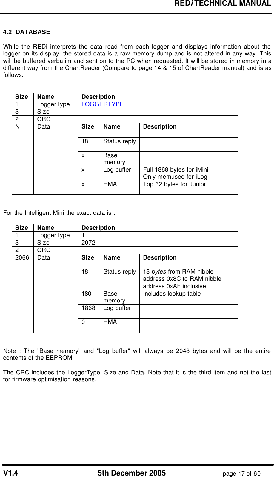

![REDi TECHNICAL MANUAL V1.4 5th December 2005 page 20 of 60 4.4 Header Structure REDi header structure as stored in the first 256 bytes of each logger image in Flash. typedef struct PreLoggerHeader { uchar LoggerType; // 0x01 = RF Mini uchar SerialNumber[4]; // as per Mini uchar Address[3]; // not relevant in Flash copy uchar Length[3]; // not relevant in Flash copy uchar Description[25]; uchar BatStat; // 1 = OK, 0 = Low ulong StartTime; // seconds since Midnight Dec 31 1999 ulong LoggingInterval; // in seconds uchar StartTimeOffset; // day light saving in Geoffs strange format ulong NumReadings; ulong FirstLogAddress; // offset from the start of the loggers EEPROM dump uint ProgramStatus; // same format as Mini ulong MaxLoggingNum; // Num of logging to take uint TripNum; ulong StartDelay; // in seconds uchar NumberOfSensors; short Sens1UpperSpec; // temperature in "Mini format" short Sens1LowerSpec; short Sens1Max; short Sens1Min; short Sens1Avg; ushint Sens1Alarm; // bit 0 = low alarm, bit 1 = high alarm uchar Sens1AlarmDelay; uchar Sens1Range; // 9 = D range, 17 = LCDMini Celsius, 18 = LCDMini Fahrenheit short Sens2UpperSpec; short Sens2LowerSpec; short Sens2Max; short Sens2Min; short Sens2Avg; ushint Sens2Alarm; uchar Sens2AlarmDelay; uchar Sens2Range; uchar Sens3UpperSpec; uchar Sens3LowerSpec; short Sens3Max; short Sens3Min; short Sens3Avg; ushint Sens3Alarm; uchar Sens3AlarmDelay; uchar Sens3Range; short E2Offset; // not relevant in Flash copy ushint Flags; // not relevant in Flash copy } PreLoggerHeader; Note : uchar is 1 byte ulong is 4 bytes LSB first uint is 2 bytes LSB first short is 2 bytes LSB first ushint (unsigned short int) is 2 bytes LSB first](https://usermanual.wiki/Escort-Data-Logging-Systems/REDI.TECHNICAL-MANUAL/User-Guide-640557-Page-20.png)
![REDi TECHNICAL MANUAL V1.4 5th December 2005 page 21 of 60 4.5 REDi Memory Map (f/w ver. 1.01f) Structure of the data stored in the 2k EEPROM Add. Name Description 0x00 3 MemLeft Amount of free Flash memory remaining 0x03 2 NextFree Next free address in the EEPROM where an index to logger data can be stored 0x05 12x Start of index table The logger image index table (see section 4.1) 0x793 13 Not used 0x7A0 4 Serial Number The serial number of this REDi. 8 BCD digits. YYWW.IIII 0x7A4 2 Product ID LSB: Minor is Product code 0 = REDi. MSB: Brand code 0 = EDLS, [1 = Cox,] 2 = Digitron. 0x7A6 2 Hardware version 1=916, 2=868, 3=433MHz 0x7A8 4 Network address Available for REDi's on a multidrop network Initially this will always be 0x0000 Upper 2 bytes not used 0x7AC 2 CRC CRC of the S/N, Product ID, H/W version and Network address 0x7AE 1 Sensor type (Not used) 0x7AF 1 BackLight time Number of seconds before the backlight goes out 0x7B0 1 Auto off time Number of minutes before the REDi shuts down 0x7B1 1 Num Recent Number of loggers for the "View recent" option 0x7B2 1 Contrast Contrast setting (no longer used) 0x7B3 1 Temperature units "C" or "F" as an ASCII digit 0x7B4 6 Date format 5 digits, NULL terminated eg. "m-d-y", "d-m-Y" 0x7BA 2 Base year 0x7BC 9 Time format 8 digits NULL terminated eg. "12:00:00", "24:00". Actually only second digit check for either 12 or 24 0x7C6 2 Last page refreshed Records the page to be refreshed in Flash for long term data retention 0x7C8 1 Description length The length of the description in bytes 0x7C9 42 Description Description stored as ASCII 0x7F3 1 Not Used 0x7F4 1 Baud rate (Not used) hard coded at 9600 baud 0x7F5 1 RS232 timeout (Not used) hard coded at 2s 0x7F6 1 Preset battery type Bit 7 = Rechergeable 0x7F7 2 Low batt voltage level BCD, LSB first eg. 0x02, 0x35 means 2.35V 0x7F9 1 Disable watchdog Bit 0 : 1 = disable, 0 = enable 0x7FA 1 Crash recovery FALSE written here during normal power down 0x7FB 1 Password flags bit 5,6,7 - spare bit 4 - the password is masked by asterisks bit 3 - the user can erase data blocks bit 2 - Password is NOT required bit 1 - the user can re-program loggers bit 0 - the user can list loggers 0x7FC 4 Password 4 ASCII digits (only 0-9 are valid) Unless otherwise stated multibyte values are LSB at lower address.](https://usermanual.wiki/Escort-Data-Logging-Systems/REDI.TECHNICAL-MANUAL/User-Guide-640557-Page-21.png)
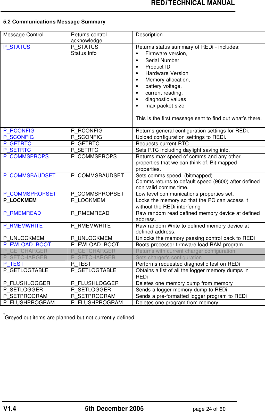
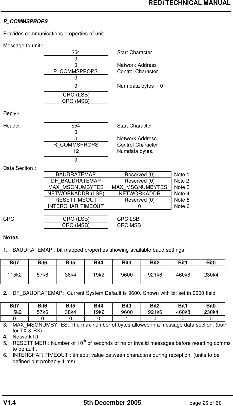
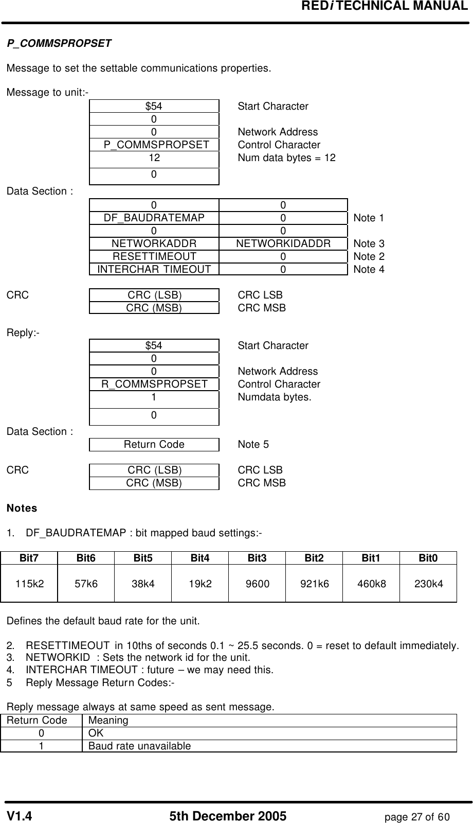
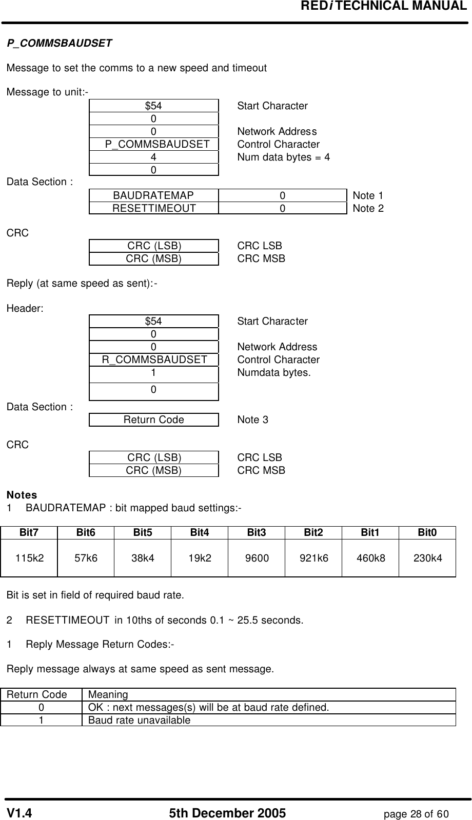
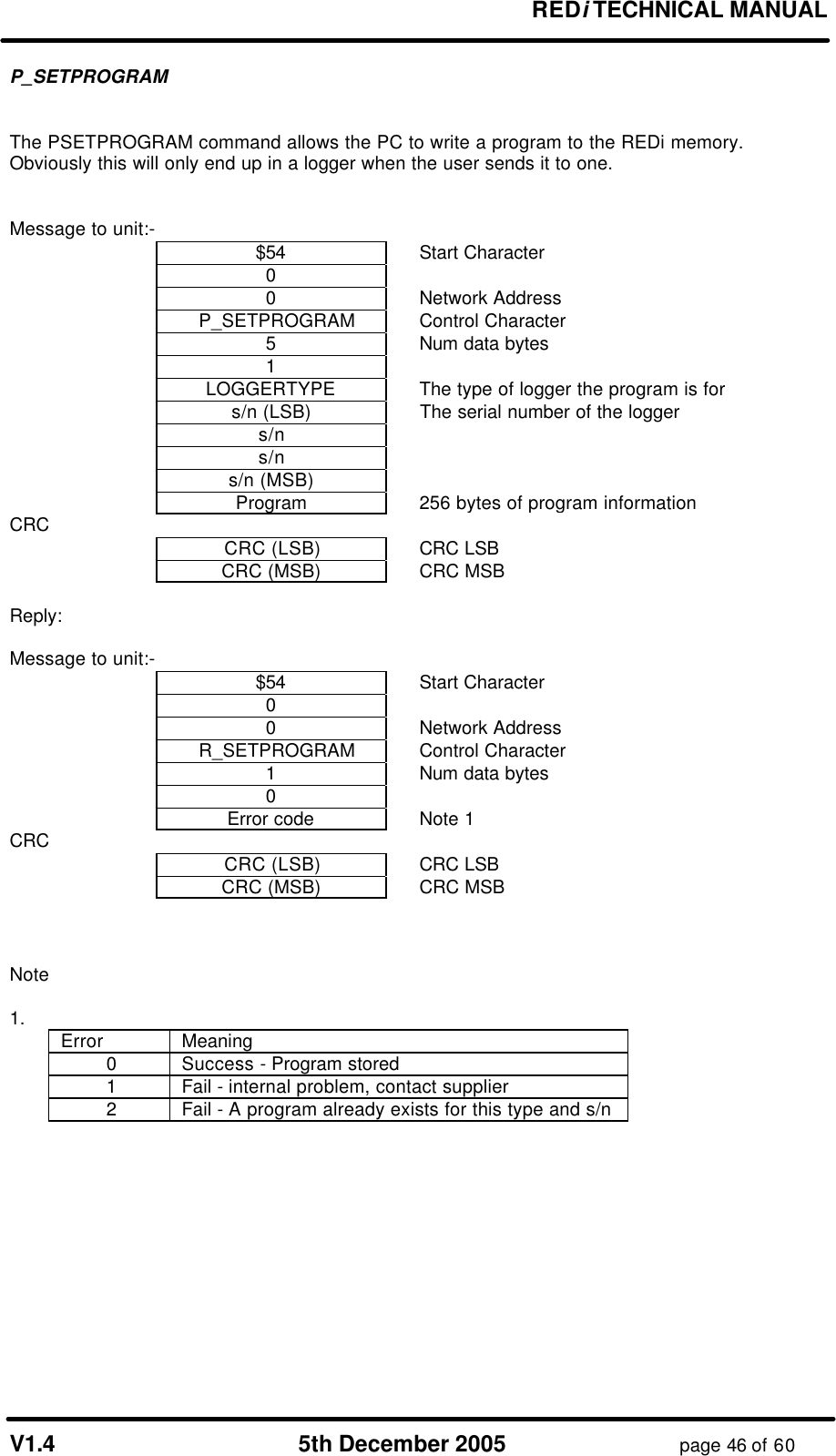
![REDi TECHNICAL MANUAL V1.4 5th December 2005 page 25 of 60 5.3 Communications Message Protocols P_STATUS This message is to be used as the first enquiry message to determine the type and firmware. All multibyte quantities are "little endian" (lowest byte at lowest address). Msg to unit:- $54 Start Character 0 0 Network Address P_STATUS Control Character 0 0 Num data bytes = 0 CRC (LSB) CRC (MSB) Reply:- Header: $54 Start Character 0 0 Network Address (either broadcast 0 or my NETWORKADDR) R_STATUS Control Character $40 Numdata bytes = 64 0 Data Section : 0 FWVER_MINOR FWVER_MAJOR 2 SERIALNUM (LSB) SERIALNUM 4 SERIALNUM SERIALNUM (MSB) Note 1 6 PRODUCTID_MINOR PRODUCTID_MAJOR Note 2 8 HARDWARE_VERSION 1=916, 2=868, 3=433MHz 10 NETWORKADDR (LSB) NETWORKADDR (MSB) Current Unique Network Addr 12 MEMSIZE (LSB) MEMSIZE for logger memory dumps etc. 14 MEMSIZE MEMSIZE (MSB) 16 FREEMEM (LSB) FREEMEM free memory remaining 18 FREEMEM FREEMEM (MSB) 20 0 0 22 0 0 24 BATTERYVOLTS_LSB BATTERYVOLTS_MSB BCD format xx.xx 0xFFFF if reading fails 26 0 0 28 SYSTEM_STATUS_L SYSTEM_STATUS_M Note 3 30 0 0 32 MEMORY_STS MEMORY_STS 0=unlocked, 1 locked by M16, 2 = locked by PC 34 BUILD_NUMBER_L BUILD_NUMBER_M 16-bit int 36 1 = SAFE_MODE PASSWORD FLAGS 38 PASSWORD_1 PASSWORD_2 40 PASSWORD_3 PASSWORD_4 : : 62 0 0 CRC (LSB) CRC (MSB) CRC Notes 1. The serial number of the unit. (XXXX.XXXX). BCD format YYWW.IIII. 2. Product ID: Major is Brand code 0 = EDLS, [1 = Cox,] 2 = Digitron. Minor is Product code 0 = REDi. 3. System Status Bit # Meaning of SET bit 0 External Power connected 1 Battery Overtemp warning (discontinued) 2 Charging now 3 Rechargeable batteries fitted 4 Charger suspended (e.g. no battery, or faulty battery detected) 5 Required password has not been entered correctly (into REDi) 6-15 Clear (always 0)](https://usermanual.wiki/Escort-Data-Logging-Systems/REDI.TECHNICAL-MANUAL/User-Guide-640557-Page-25.png)
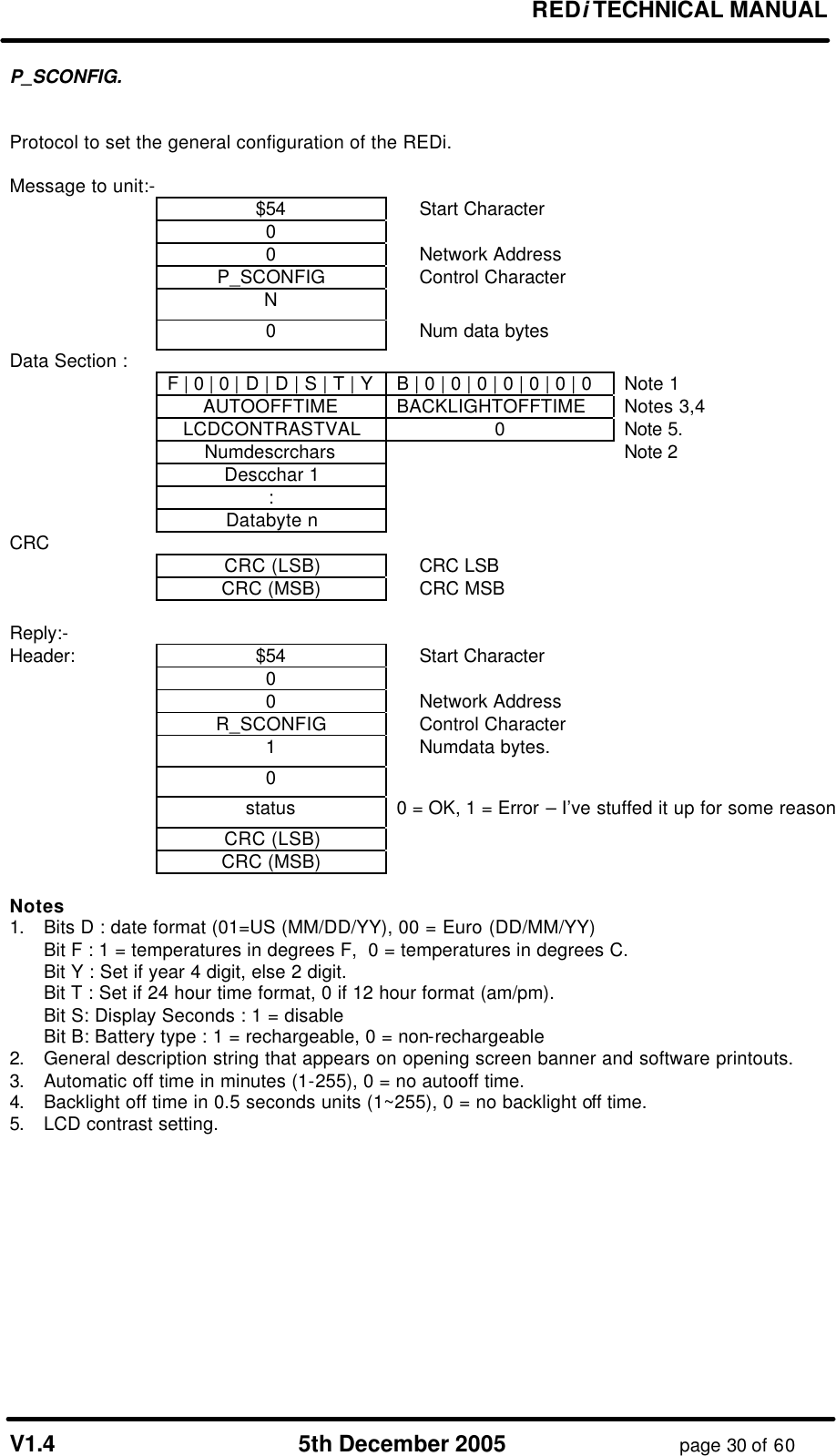
![REDi TECHNICAL MANUAL V1.4 5th December 2005 page 29 of 60 P_RCONFIG. Protocol to read the general configuration of the REDi. The configuration contains:- • Degrees C or F display • Date & Time format (MM/DD/[YY]YY or DD/MM/[YY]YY) • General description string (max 42 characters) • LCD contrast setting • Backlight off time (if backlight installed) • Automatic turn-off time. Message to unit:- $54 Start Character 0 0 Network Address P_RCONFIG Control Character 0 0 Num data bytes = 0 CRC (LSB) CRC (MSB) Reply:- Header: $54 Start Character 0 0 Network Address R_RCONFIG Control Character N Numdata bytes. 0 Data Section : F | 0 | 0 | D | D | S | T | Y N|0|0|0|0|0|0|0 Note 1 AUTOOFFTIME BACKLIGHTOFFTIME Notes 3,4 LCDCONTRASTVAL 0 Note 5. Numdescrchars Note 2 Descchar 1 : Databyte n CRC CRC (LSB) CRC LSB CRC (MSB) CRC MSB Notes 1. Bit D : date format (1=US (MM/DD/YY), 0 = Euro (DD/MM/YY) Bit F : 1 = temperatures in degrees F, 0 = temperatures in degrees C. Bit Y : Set if year 4 digit, else 2 digit. Bit T : Set if 24 hour time format, 0 if 12 hour format (am/pm). Bit S: Display Seconds : 1 = disable Bit N: Set if recharging of batteries is allowed 2. General description string that appears on opening screen banner and software printouts. 3. Automatic off time in minutes (1-255), 0 = no autooff time. 4. Backlight off time in 1 second units (1~255), 0 = no backlight off time. 5. LCD contrast setting.](https://usermanual.wiki/Escort-Data-Logging-Systems/REDI.TECHNICAL-MANUAL/User-Guide-640557-Page-29.png)
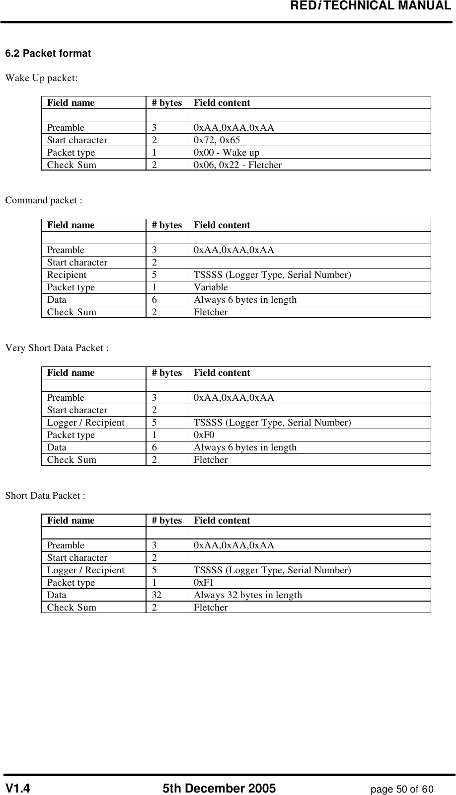
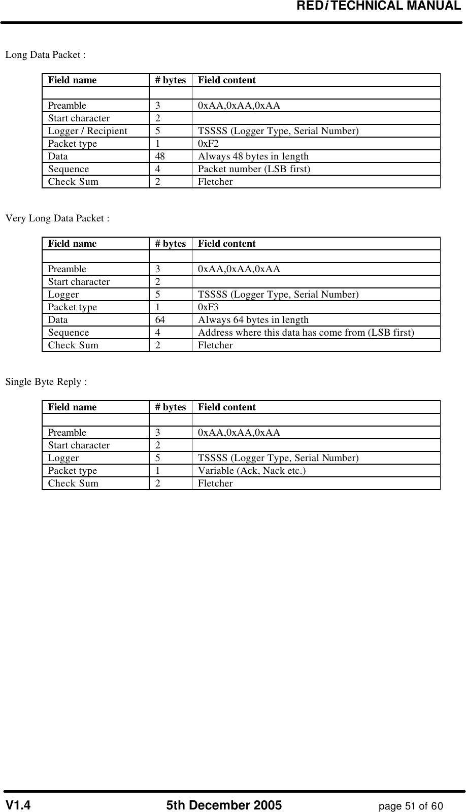
![REDi TECHNICAL MANUAL V1.4 5th December 2005 page 52 of 60 6.3 Specific packet types REDi to Logger Name Packet ID (PType) Packet Type Recipient Data Description Wake Up 0x00 Wake up Non specific none Broadcast over and over for 1 second to wake up all loggers. Ack 0x01 Single Byte Reply TT,SN,SN,SN,SN none Acknowledgement of correct reception of a packet. Resend 0x02 Single Byte Reply TT,SN,SN,SN,SN none Request for a retransmission of the last packet. Who's There ? 0x11 Command 0xFF,0xFF,0xFF, 0xFF,0xFF all blank Request for loggers to identify themselves. Don't reply to "Who's There ?" 0x11 Command TT,SN,SN,SN,SN all blank Tells the specified logger not to reply to the general "Who's There ?" packet. Read Data 0x12 Command TT,SN,SN,SN,SN D[0:2] : address to read from D[3:5] : length required Request for the logger to begin sending a series of data packets. Status Request 0x14 Command TT,SN,SN,SN,SN all blank Request for the loggers status packet. How much data do you have ? 0x15 Command TT,SN,SN,SN,SN all blank Request for the size of data that the logger holds. Program Logger 0x16 Command TT,SN,SN,SN,SN D0 : # of packets that follow D1 : flags D[2:5] : security code The command to initiate reprogramming or restarting a logger. "Logger Program" packets may follow this. Check Lease Count 0x17 Command TT,SN,SN,SN,SN all blank Request for the logger to check the lease count now. Logger Program 0xF2 Long Data TT,SN,SN,SN,SN See section 3.5 on programming a logger. Data packets containing the data and locations of a loggers program. Logger to REDi Name Packet ID (PType) Packet Type Data Description Ack 0x01 Single Byte Reply none Acknowledgement of a correctly received packet. Nack 0x03 Single Byte Reply none The packet was received but was not or cannot be processed. [no longer used] Bad Password 0x04 Single Byte Reply none Reply when a "Program Logger" packet was received and the logger required a password and the password was incorrect. Lease Expired 0x05 Single Byte Reply none Reply when a "Program Logger" packet was received but the logger's lease had expired. Data Request Reply 0xF3 Very Long Data Packet 64 bytes of logger data A block of data read out of the logger's EEPROM. Data Size Reply 0xF0 Very Short Data Packet D[0:2] : data length D[3:5] : start address Reply to the "How much data do you have ?" packet. Status Reply 0x14 Short Data Packet D[0:1] : Implant f/w D[2:3] : Logger f/w D4 : Case type D[5:22] : Status packet from host logger D[23:end] : padding Reply to a Status Request packet. All multi byte quantities have MSB at the highest address. For a more detailed description of each process please refer to the "Wireless Mini Technical Manual - Implant".](https://usermanual.wiki/Escort-Data-Logging-Systems/REDI.TECHNICAL-MANUAL/User-Guide-640557-Page-52.png)

![REDi TECHNICAL MANUAL V1.4 5th December 2005 page 58 of 60 entirety to Flash (if there have been writes) then the new page is read from Flash. As with all flash devices time must be allowed for the memory to sink in after a write before other pages can be accessed. In the interest of high speed data transfer, however, the RF code as well as much of the other code reads and writes pages directly as blocks of 256 bytes. The start of the RS232 Tx buffer is used for this. To avoid getting out of sync with the 'linear address space' system BringFlashUpToDate() must be called before directly reading and writing pages from/to the serial flash. This will ensure that anything that was written to the RAM buffer actually does get updated to the memory chip and anything that system doesn't believe that old data sitting in the RAM buffer is current. This is all a bit messy but works well and was required to get quick and reliable timing for the RF code while not rewriting lots of the existing code that REDi was built on. GLCD.C This module contains the code to draw text and graphics on the LCD. The display has an effective 'cursor position' which defines where characters are to be put. This will increment as expected as characters are drawn much like printf(""). The cursor position can be read or changed with glgetXY() and glgoto(). The home position (0,0) for text or graphics is the top left hand corner of the display. Generally the code only needs to call the relevant text or graphic function, which updates an image of the display stored in M16 RAM, and the changes will be 'blitted' to the display controller chip when the blitting interrupt next occurs (every 50ms). If, however, the interrupts are disabled, such as during RF transfers, then the code must call the relevant text or graphic function then explicitly call a function called glcd_send_bitmap() to get the changes to appear on the LCD. If time is an issue then another function called glcd_update_slice() can be used which only blits a specific area of the display. The remaining area remains unchanged. I2C.C This module contains code to bit-bash either of the two I2C busses on the main board (one for 2k EEPROM and one for the RTC). The main functions of interest are I2CRead() and I2CWrite() which linearise the address paging and handle timing considerations for writing. INT.C This module contains the system interrupts. These include RS232 in, RS232 out, system tick, wake up on key press, wake up from external power application, wake up on RS232 connection, RTC interrupt (not used), and Watch Dog (normally disabled). The system tick occurs every 50ms and is used for beep termination, keyboard scanning and display blitting. After 20 systems ticks (one second) the trickle charger, back light timer, and comms-mode symbol are checked. After 1200 systems ticks (one minute) the auto-off timer and battery charge timers are checked. KEYBOARD.C This module contains routines for reading the keyboard. In the function ScanKeyboard() the keyboard is scanned as a matrix and the global variables gKeymap[n] are set up which contain the state of the keypad. This function also returns a variable denoting the current key that is pressed (or the first one detected if more than one key is pressed). This function is usually called every 50ms by the system interrupt and used to set up the global variable uKey which can be used by other code ie. in the function ProcessKeys() in PROCESS.C. The keyboard can be used to trigger interrupts but this is only done for waking from sleep. There is also a function called SetBeeper() which can be used to turn the beeper on. The beeper will then continue beeping until an interrupt turns it off. MAIN.C This is highest level function. It contains the "main" function which continuously loops until something happens. Note that some of the processing such as servicing RS232 requests or](https://usermanual.wiki/Escort-Data-Logging-Systems/REDI.TECHNICAL-MANUAL/User-Guide-640557-Page-58.png)